1938 Building Code - ARTICLE 9
69
ARTICLE 9. CONSTRUCTION Sub-Article 1. Workmanship (8.1.1). §C26-380.0 Workmanship on Wood Frame Structures.-Structural members of wood shall be so framed, anchored, tied and mutually braced as to develop the strength and rigidity necessary to their purpose or use and to develop at least the safe strength of their details and connections. Fabrication and workmanship shall conform to good engineering and trade practice. (8.1.2) §C26-381.0 Workmanship on Welded Structures.- a. It shall be unlawful for any person to perform any structural welding work until such person has obtained from the examiners for welders, after examination and submission of evidence of experience and ability, a certificate attesting to his fitness for the performance of such work. b. Before the examiners for welders shall issue a certificate of qualification, the applicant shall pass the operator qualification tests prescribed in part II, operator qualification of the standard qualification procedure, 1941 edition, issued by the American Welding Society. Such qualification tests shall be conducted by the examiners for welders or their representative, but in the discretion of the examiners for welders, documentary or other evidence or both to the effect that the applicant has passed the prescribed qualification tests, conducted by a standard testing laboratory may be accepted as satisfactory proof of such applicant's fitness to make structural welds. c. The quality of welds permitted under this title shall conform to the requirements of section 2, design of welded connections and section 4, workmanship of the standard code for arc and gas welding in building construction, 1946 edition, of the American Welding Society. (8.1.3). §C26-382.0 Repealed December, 1962. Sub-Article 2. Excavations (8.2.1). §C26-383.0 Owner.-The responsibility of affording any license referred to in sections C26-383.0 through C26-390.0, and sections C26-561.0 through C26-570.0, shall rest upon the owner but in case the tenant of any such owner fails or refuses to permit such owner to afford such license, such failure shall be a cause to the owner for dispossessing such tenant through proceedings provided in the civil practice act for recovering possession of real property. In case the duty devolves upon such owner to make his premises safe under any of the provisions of sections C26-383.0 through C26-390.0 and sections C26-561.0 through C26-570.0, such owner shall have a like remedy against a tenant of a part of the premises. (8.2.2.1). §C26-384.0 Excavations Affecting Adjoining Property.- a. Temporary Support of Adjoining Property.-Any person causing any excavation to be made shall provide such sheet piling and bracing as may be necessary to prevent the earth of adjoining property from caving in before permanent supports have been provided for the sides of such excavation. (8.2.2). b. Permanent Support of Adjoining Property.-Whenever provisions are lacking for the permanent support of the sides of an excavation in accordance with the provisions of section C26-563.0, a person causing such excavation to be made shall build a retaining wall at his own expense and on his own land. Such retaining wall shall be carried to a height sufficient to retain the adjoining earth, shall be properly coped and shall be provided with a substantial guard rail or fence four feet high.
Transcript of 1938 Building Code - ARTICLE 9

ARTICLE 9. CONSTRUCTION
Sub-Article 1. Workmanship
(8.1.1). §C26-380.0 Workmanship on Wood Frame Structures.-Structural members of wood
shall be so framed, anchored, tied and mutually braced as to develop the strength and rigidity
necessary to their purpose or use and to develop at least the safe strength of their details and
connections. Fabrication and workmanship shall conform to good engineering and trade practice.
(8.1.2) §C26-381.0 Workmanship on Welded Structures.- a. It shall be unlawful for any person to perform any structural welding work until such
person has obtained from the examiners for welders, after examination and submission of
evidence of experience and ability, a certificate attesting to his fitness for the performance of
such work.
b. Before the examiners for welders shall issue a certificate of qualification, the applicant
shall pass the operator qualification tests prescribed in part II, operator qualification of the
standard qualification procedure, 1941 edition, issued by the American Welding Society.
Such qualification tests shall be conducted by the examiners for welders or their
representative, but in the discretion of the examiners for welders, documentary or other
evidence or both to the effect that the applicant has passed the prescribed qualification tests,
conducted by a standard testing laboratory may be accepted as satisfactory proof of such
applicant's fitness to make structural welds.
c. The quality of welds permitted under this title shall conform to the requirements of section
2, design of welded connections and section 4, workmanship of the standard code for arc and
gas welding in building construction, 1946 edition, of the American Welding Society.
(8.1.3). §C26-382.0 Repealed December, 1962.
Sub-Article 2. Excavations
(8.2.1). §C26-383.0 Owner.-The responsibility of affording any license referred to in sections
C26-383.0 through C26-390.0, and sections C26-561.0 through C26-570.0, shall rest upon the
owner but in case the tenant of any such owner fails or refuses to permit such owner to afford
such license, such failure shall be a cause to the owner for dispossessing such tenant through
proceedings provided in the civil practice act for recovering possession of real property. In case
the duty devolves upon such owner to make his premises safe under any of the provisions of
sections C26-383.0 through C26-390.0 and sections C26-561.0 through C26-570.0, such owner
shall have a like remedy against a tenant of a part of the premises.
(8.2.2.1). §C26-384.0 Excavations Affecting Adjoining Property.-
a. Temporary Support of Adjoining Property.-Any person causing any excavation to be made
shall provide such sheet piling and bracing as may be necessary to prevent the earth of
adjoining property from caving in before permanent supports have been provided for the
sides of such excavation.
(8.2.2). b. Permanent Support of Adjoining Property.-Whenever provisions are lacking for
the permanent support of the sides of an excavation in accordance with the provisions of
section C26-563.0, a person causing such excavation to be made shall build a retaining wall
at his own expense and on his own land. Such retaining wall shall be carried to a height
sufficient to retain the adjoining earth, shall be properly coped and shall be provided with a
substantial guard rail or fence four feet high.

(8.2.2.3). c. License to Enter Adjoining Premises.-For the purpose of subdivisions a and b of
this section, any person causing an excavation to be made shall be afforded the license
necessary to enter the adjoining premises. If such license is not afforded, the owner of the
adjoining premises shall have the responsibility of providing temporary and permanent
support of his premises at his own expense, and for that purpose such owner shall be afforded
the license necessary to enter the premises where such excavation is to be made.
(8.2.3.1). §C26-385.0 Excavations Affecting Adjoining Structures.-
a. Excavations More Than Ten Feet Deep.-Whenever an excavation is carried to a depth of
more than ten feet below the curb, the person who causes such excavation to be made shall, if
afforded the license necessary to enter the adjoining premises, at all times and at his own
expense, preserve and protect from injury any structure the safety of which may be affected
by such part of the excavation as extends more than ten feet below the curb, and such person
shall support the adjoining structure by proper foundations, whether or not such structure is
more than ten feet below the curb. If the necessary license is not afforded to the person
causing the excavation to be made, it shall be the duty of the owner who fails to afford such
license to make the structure safe, and to support such structure by proper foundations, and
such owner shall, if it is necessary for such purpose, be afforded the license necessary to
enter the premises where such excavation is to be made.
(8.2.3.2). b. Excavations Ten Feet or Less in Depth.-The owner of any structure, the safety of
which may be affected by an excavation, shall preserve and protect such structure from
injury and shall support such structure by proper foundations, except as otherwise provided
in subdivision a of this section and shall, if it is necessary for such purpose, be afforded the
license necessary to enter the premises where the excavation is to be made.
(8.2.3.4). c. Support of Party Walls.-In case an adjoining party wall is intended to be used by
the person who causes an excavation to be made, and such party wall is in good condition
and sufficient for the uses of the existing and proposed buildings, such person shall, at his
own expense, preserve such party wall from injury and support it by proper foundations, so
that it shall be and remain practically as safe as it was before the excavation was commenced.
(8.2.3.5). d. Weather Protection.-Where permission has been given under this section to any
person to enter any adjoining structure, such person shall provide for such adjoining structure
adequate protection against any danger of injury due to the elements which may result from
such entry.
(8.2.4). §C26-386.0 Structures Unsafe at Commencement of Excavation or Demolition.-If
the person who causes an excavation to be made or an existing structure to be demolished has
reason to believe an adjoining structure is unsafe, such person shall forthwith report his belief in
writing to the superintendent, who shall cause an inspection of such premises to be made, and if
such structure is found unsafe, he shall declare such structure unsafe and shall cause it to be
repaired as provided in sections C26-193.0 through C26-201.0.
(8.2.5). §C26-387.0 Physical Examination of Adjoining Property Prior to and During
Excavation or Demolition.-A license to enter upon adjoining property for the purpose of
physical examination of such property, prior to the commencement and at reasonable periods
during the progress of the excavation or demolition shall be afforded by the owner and tenants of
such adjoining property to the person causing such excavation or demolition to be made.

(8.2.6). §C26-388.0 Excavations Other Than For Construction Purposes.- a. An excavation made for the purpose of taking soil, earth, sand, gravel, or other material
shall be made in such a manner as will prevent injury to neighboring properties, to the street
which adjoins the lot where such excavation is made, and to the public health and comfort.
b. Such excavations shall not be commenced until a permit therefor has been obtained from
the superintendent.
c. Applications for permits shall be such form as may be prescribed by the commissioner and
shall be accompanied by a plot plan on which is indicated the location of the plot, the exact
location of the proposed excavation and the area and depth of the excavation.
d. Permits for the operation of such excavations shall be issued only upon proof by the
applicant that the land is free from any lien for unpaid city taxes, assessments, water rates,
bail bonds and judgments obtained by the city. In addition, if the owner shall be under legal
age the consent of the surrogate's court must be submitted. If there is an unpaid mortgage
upon the property, the consent of the mortgages must also be submitted.
e. It shall be unlawful for any such excavation to exceed a depth greater than ten feet below
the grade of the street or streets adjacent thereto, as may have been established by the board
of estimate and shown upon the city map, unless the side walls of such excavation be
maintained at an incline of not less than forty-five degrees from horizontal or the side walls
be supported by piling or other retaining equipment equal to that specified for building
excavations.
f. Such excavation shall be properly drained as long as the excavation remains.
g. Any such abandoned excavation which shall become unsafe, menacing or dangerous to life
or limb, shall be filled in by the owner, as the superintendent may require with clean ashes,
sand or earth or otherwise made safe and secure.
h. Any person who shall violate any provision of this section upon conviction thereof, shall
be punished by a fine of not more than five hundred dollars or by imprisonment of not more
than three months or both.
i. If any provision of this section shall be held invalid or ineffective in whole or in part or
inapplicable to any person or situation, it is the purpose and intent of this section that all
other provisions thereof shall nevertheless be separately and fully effective and that the
application of any such provision to other persons or situations shall not be affected.
(8.2.7). §C26-389.0. Protection At Excavations.-Guards or fences shall be provided along the
open sides of excavations, except that, in the discretion of the superintendent, such guards or
fences may be omitted from any side or sides other than such as are adjacent to streets or public
passageways. Suitable means of exit from excavations shall be provided.
(8.2.8). §C26-390.0 Abandoned Foundations-Safety and Protection.-Any abandoned
foundation which shall become unsafe, menacing or dangerous to life or limb, shall be filled in,
as the superintendent may require, with clean ashes, sand or earth or otherwise made safe and
secure.

Sub-Article 3. Foundations
GROUP 1
General
(8.3). §C26-391.0 General.-
a. The foundation loads of permanent structures shall be carried down to satisfactory bearing
materials so that the entire transmitted load will be distributed over the supporting soils at
any depth beneath the foundation at unit intensities within the allowable bearing values
established by this title and by sections C26-376.0 through C26-379.0. Any type of pile or
other foundation construction unprovided for in this title shall meet, in addition to the
requirements of this article, all the requirements which may be established by the rules of the
board.
b. The provisions of sub-article 3 apply to all vertical and lateral loads and forces on
foundations.
c. Foundations supporting rigid frame structures shall be designed so as to minimize
differential displacements and to avoid displacements on such magnitude that they would
overstress the superstructure.
GROUP 2
Footings
(8.3.1.1). §C26-392.0 Spread of Footings.-The superintendent shall have authority to permit or
require a variation in unit loads between different footings on the same plot, when in his opinion
such variation may be desirable or necessary to secure adequate stability in the structure.
(8.3.1.2). §C26-393.0 Levels of Footings.-Where footings are on sloping ground or where the
bottoms of footings in a structure are on different levels or are on levels different from the
footings of adjoining structures, the plans submitted must include vertical cross-sections to
natural scale, showing all such variations in level. When such change of level occurs, adequate
provision shall be made for the lateral support of the material supporting the higher footing.
(8.3.1.3). §C26-394.0 Wood Footings.-Wood footings may be used only for wood frame
structures, if such footings are placed entirely below the permanent water level, or for capping
wood piles which project above water level in foundations for wood frame structures over
submerged or marsh lands.
(8.3.1.4). §C26-395.0. Concrete footings.-Concrete footings shall comply with requirements of
sections C26-1547.0 through C26-1555.0 of this code.
(8.3.1.5). §C26-396.0 Masonry Footings.-
a. Masonry footings other than concrete for walls and piers shall be of solid masonry and
shall have an area sufficient to distribute the superimposed load in accordance with the
bearing capacity of the soil upon which such footings are built. When such footings rest upon
other than solid rock, they shall extend at least four feet below finished grades. Masonry
footings shall be laid in cement mortar or cement-lime mortar, shall be at least eight inches
wider than the foundation wall above, and shall have a depth at least equal to the total
projection beyond the foundation walls next above.
b. When brickwork in foundation walls is stepped up from the footings, the maximum offset,
if the brickwork is laid in single courses, shall be one and one-half inches, and if laid in
double courses, three inches.

c. Footings of concrete masonry shall also conform to the requirements of sections C26-
395.0, and C26-400.0.
(8.3.1.6). C26-397.0 Masonry Foundations.-
a. General-
1. Foundation walls shall have a thickness at least equal to that of the wall next above,
and at least equal to the thicknesses given in inches in the table below:
Solid
masonry
Hollow
masonry
Hollow
walls of
brick
Rubble
stone
masonry
Private dwellings at most twenty feet
high and one-story structures at most
twenty feet high
8 12 12 16
Private dwelling over twenty feet high
or other structures of more than one
story and over twenty feet high
12 16 16 16
2. Foundation walls of hollow blocks may be used above grade when the upper walls are
of wood frame or of hollow building block construction. All other foundation walls shall
be of solid masonry, except when the structure is without basement or cellar.
(8.3.1.6.1). b. Mortar.-Foundation walls built of masonry units shall be laid in cement mortar
or cement-lime mortar.
(8.3.1.6.2). c. Thickness.-
1. In structures over two stories high, except private residences, foundation walls shall be
at least four inches thicker than the wall section next above, except that when the walls
are of hollow units or are hollow walls of brick, the foundation walls may be of the same
thickness as the walls next above, provided such foundation walls are built of solid
masonry or concrete and that a maximum of two stories above the foundation are of the
same thickness. Foundation walls of reinforced concrete shall comply with the
requirements of sections C26-468.0 through C-26-509.0.
2. Every foundation wall serving as a retaining wall shall be designed to support safely all
vertical and lateral loads to which such foundation wall may be subjected. It shall be
unlawful to have tensile stresses in any masonry, except where such masonry is properly
reinforced. The maximum compressive stresses due to combined dead, live and lateral
loads shall be within those permitted in sections C26-355.0 through C26-362.0.
3. When any foundation wall other than a retaining wall extends more than thirteen feet
below the top of the first floor beams, such extended portion shall be increased by at least
four inches for each interval of thirteen feet or fraction thereof, except when such portion
is adequately braced by an intermediate floor construction.
(8.3.1.6.3). d. All masonry walls enclosing cellars, basements and lower floors below ground
in all residential buildings hereafter erected shall be waterproofed by a method approved by
the board.
(8.3.1.7). §C26-398.0 Steel Grillage Footings.-Steel grillage beams may be used in footings, but
when such beams are used on yielding soils, they shall rest upon a bed of concrete, at least eight
inches thick, mixed in compliance with section C26-311.0. In all cases such beams shall be
entirely encased by at least four inches of concrete of the same quality, and the spaces between
beams shall be entirely filled with concrete, or with grout of one to two mixture by volume. The
beams shall be provided with proper spacers.
(8.3.1.8). §C26-399.0 Pressure Under Footings.- a. In the case of loads exerting pressure under the footings of foundations, the full dead loads,
including the weight of the foundations, and the figured total live loads from all floors on the
lowest tier of columns, piers or walls shall be taken. For this purpose the reduced live loads
permitted by section C26-348.0, may be used.
b. Where a footing is subject to a combination of pressure from wind and from live and dead
loads, the normal pressure may be increased by thirty-three and one-third percent, provided
the area of the footing thus found is at least that required for the live and dead loads alone.
Where the pressure on any footing, due to wind, is less than thirty-three and one-third percent
of the pressure due to live and dead loads, such pressure may be neglected.
(8.3.1.9) §C26-400.0 Design of Footings.-
a. Footings shall be designed so as to properly distribute their loads within the allowed
bearing capacities of soils as established by sections C26-376.0 through C26-379.0, and so as
to insure that the stresses in the materials shall be within those fixed by sections C26-354.0
through C26-375.0.
Subd. b. repealed Dec. 1962.
(8.3.1.10). §C26-401.0 Eccentric Footings.-Eccentricity of loading in foundation shall be fully
investigated and the maximum loading shall be kept within the approved safe loads of the
supporting soil.
(8.3.1.11). §C26-402.0 Weight of Foundations, Fill and Floors.-The weight of foundations and
of overlying fill and floors shall be included in the dead load for which provision shall be made.
(8.3.1.12). §C26-403.0 Depth of Foundations.-Footings, piers or pile caps exposed to frost
shall, unless such footings, piers and caps are on sound rock, be carried down at least four feet
below the adjoining ground surface. It shall be unlawful to lay footings in freezing weather,
unless adequate precautions are taken against frost action. It shall be unlawful to lay footings,
piers or pile caps on frozen soil.
(8.3.1.13). §C26-404.0 Foundation Piers.-
a. The minimum diameter of foundation piers shall be two feet and the method of their
installation and construction shall be such as to provide for accurate preparation and
inspection of their bottoms, and to insure sound concrete or other masonry.
b. The design of foundation piers shall be governed by the requirements of article eight of
this title.
c. The height shall in all cases be at most twelve times the least horizontal dimension.
d. Foundation piers of concrete shall comply with the requirements of section C26-1556.0.
GROUP 3
Pile Foundations
(8.3.2.1.1). §C26-405.0 General Requirements.-
a. Definition of a Pile.-A “pile” is a structural unit introduced into the ground to transmit
loads to lower strata or to alter the physical properties of the ground, and is of such shape,
size and length that the supporting material immediately underlying the base of the unit
cannot be manually inspected.
b. General.-All piles shall conform to the requirements of this Group 3 and of such other
provisions of the Code as are referred to in Group 3.
c. Evaluation of Supporting Materials for Pile Foundations.-The bearing values of soils
supporting pile foundations shall be evaluated by one of the following methods in accordance

with the provisions of the sections specified herein; (a) the resistance to driving of piles,
section C26-405.2, h; (b) pile load tests, section C26-405.2. i; (c) the resistance to jacking,
section C26-405.2, j. The above values may be modified as required by section C26-405.2,
paragraphs e, f or g. The presumptive bearing values contained in section C26-377.0 shall not
apply to pile foundations.
d. Protection of Pile Materials.-Where the boring records or site conditions indicate possible
deleterious action on pile materials because of soil constituents or of changing water levels,
such materials shall be adequately protected by approved preservatives or impervious
encasements which will not be rendered ineffective by driving and which will prevent such
deleterious action.
e. Wood Piles.-
1. Wood piles shall be cedar, cypress, Douglas fir, hickory, Norway pine, oak, Southern
pine, spruce, Western hemlock, or other similar species approved for such use. Where
required to be protected by preservatives, such treatment shall conform to the
preservative treatment hereinafter specified.
2. All wood piles shall be of sound timber suitable for driving, cut above the ground
swell, free from decay, unsound knots, knots in groups or clusters, wind-shakes and short
or reversed bends. The maximum diameter of any sound knot shall be one-third the
diameter of the pile section where the knot occurs, but not more than four inches in the
lower half of pile length nor more than five inches otherwise. All knots shall be trimmed
flush with the body of the pile and ends shall be squared with the axis. Such piles shall
have reasonably uniform taper throughout their length and shall be so straight that a line
joining the centers of point and butt shall not depart from the body of the pile. No bark or
wane shall be measured in required dimensions. The diameter at any section is the
average of the maximum and minimum dimensions at that section. All piles required to
be treated shall be thoroughly peeled.
3. For temporary structures of a minor character as approved by the superintendent and
for lightly loaded class 4 and class 5 structures, as defined in sections C26-242.0 and
C26-243.0, located over submerged or marsh land, untreated wood piles having minimum
diameters of four inches at the point and eight inches at the butt shall be permitted above
high tide level provided the top five feet of each such pile remains exposed for visual
inspection.
4. Wood piles not impregnated with an approved preservative shall not be used unless the
cut-off or top level of the pile is below permanent water table level. The permanent water
table level shall not be assumed higher than the invert level of any sewer, drain or
subsurface structure, existing or planned in the adjacent streets, nor higher than the water
level at the site resulting from the lowest drawdown of wells or sumps.
5. Creosoted timber piles when pressure treated to a final net retention of not less than
twelve pounds of creosote per cubic foot of wood may extend above permanent water
level when installed and protected in accordance with the following provisions:
(a) The tops of the cut-off piles shall be below finished ground level and shall be
treated with three coats of hot creosote oil and capped with at least average concrete
as defined in Section C26-1456.6-b.
(b) The preservative shall be grade one coal-tar creosote oil as required by United
States federal specification, No. TT-W-571-b. Preservative treatment shall be an
empty-cell process, in accordance with the same specification.
f. Rolled Structural Steel Piles.-Rolled structural steel piles shall conform as to material
to the requirements of section C26-322.0. Sections of such piles shall be of H form, with
flange projection not exceeding fourteen times the minimum thickness of metal in either
web or flange and with total flange width at least eighty-five percent of the depth of the
section. No section shall have a thickness of metal less than three-eighths of an inch.
Other structural sections or combinations of sections having flange widths and depths of
not less than ten inches and thickness of metal not less than one-half inch may also be
used.
g. Pre-cast Concrete Piles.-Pre-cast concrete piles shall be reinforced with longitudinal
reinforcing equal to at least two percent of the volume of the concrete in such piles and
with lateral reinforcing in the form of hoops or spirals of at least one-quarter inch round
rods or wires, spaced twelve inches on centers throughout the length of the pile, except in
the bottom and top three feet, where this spacing shall be reduced to not more than three
inches. The top of this pile may be cut off after driving. Reinforcing steel shall be
covered with not less than two inches of concrete. All piles shall be properly cured before
they are driven.
h. Cast-in-place Concrete Piles.-After installation to final depth and immediately before
the placing of the concrete filling, the inside of the tube, shell or bore shall be free of any
foreign matter. Concrete shall be placed by such methods that the entire volume of the
tube, shell or bore is filled. Concrete filling shall not be placed through water, unless the
superintendent specifically consents in writing to such placing, after the submission to
him of the detailed method of procedure. The concrete cap shall not be poured until at
least one hour after all piles within the cap group are completely filled.
i. Combination or Composite Piles.-Combination or composite piles may consist of two
types of piles. The maximum allowable load shall be that allowed for the weaker section.
The design of the piles shall be satisfactory to the superintendent. The connection or joint
between the two sections shall be so constructed as to prevent the separation of the upper
and lower sections during construction and thereafter.
The details and methods of making joints shall be submitted to the superintendent and
approved by him before any piles of this type are used.
j. Piles Located in Soils Subject to Physical Change or Movement.-
1. Structures on piles installed in unstable strata of soil which are or may be subject to
lateral movements shall be adequately braced by batter piles or by other effective
methods. All such piles, including the bracing piles, shall be driven to satisfactory
resistance into material of class 11, or better as classified in section C26-377.0, c,
below the lowest layer of unstable material, or to rock.
2. Piles installed in soils which exhibit considerable subsidence and consolidation
during driving, shall penetrate to satisfactory resistance into suitable underlying
material or shall be driven to rock.
k. Use of Existing Piles at demolished Structures.-
l. Piles left in place, where the structure has been demolished, shall not be used for
the support of new construction unless satisfactory evidence can be produced as to the
length and driving conditions of each pile, which evidence will prove that the piles in
question are adequate for loadings in accordance with the requirements of this group
3.

2. Where additional piles are required to support the loadings of the new structure,
then the existing piles shall be limited to seventy-five percent of their rated load-
carrying capacity as determined under subparagraph 1 above, and the additional piles
shall be of similar type and shall also be restricted to seventy-five percent of the rated
load-carrying capacity as determined by the provisions of section C26-405.2.
l. Minimum Overall Pile Dimensions.-Except as provided in section C26-405.0, e, 3, no
tapered pile shall be less than six inches in diameter at any section, nor have less than an
eight-inch diameter butt at cut-off. No pile of uniform section shall have a diameter of
less than eight inches, or, if not circular, a minimum dimension of less than seven and
one-half inches.
Tapered shoes or points of lesser dimensions may be attached to the ends of piles.
m. Minimum Spacing of Piles.-Except as provided in subparagraph 4 below, the
minimum spacing of piles shall be as follows:
1. Piles bearing on rock or penetrating into rock shall have a minimum spacing center
to center of twice the average diameter or 1.75 times the diagonal of the pile, but not
less than twenty-four inches.
2. All other piles shall have a minimum spacing center to center of twice the average
diameter or 1.75 times the diagonal of the pile, but not less than thirty inches, except
that all piles located in groups or abutting groups that receive their principal support
in materials below class 6, as classified in section C26-377.0, c, shall have their
spacing increased above the minimum values by ten percent for each interior pile up
to a maximum increase of spacing of forty percent.
3. If, because of known obstructions or space limitations, piles are originally designed
to be spaced closer than specified above, or if piles along a lot line are located less
than one-half of the required spacing, from the lot line, the carrying capacity of each
pile not sufficiently distant from another pile or from the lot line shall be reduced.
The percentage reduction in load-carrying capacity of each pile shall be one-half of
the percentage reduction in required spacing.
4. When the supporting capacity of a single row of piles is adequate for the wall of a
structure, effective measures shall be taken to provide for eccentricity and lateral
forces, or the piles shall be driven alternately in lines spaced at least one foot apart
and located symmetrically under the center of gravity of the loads carried. A single
row of piles without lateral bracing may be used for private dwellings not exceeding
two stories in height, provided the centers of the piles are located within the width of
the foundation wall.
n. Minimum Penetration.-Piles shall penetrate into soil of class 12 or better as classified in
section C26-377.0, c, at least ten feet below cut-off level and at least ten feet below ground
level. The pile point shall be at least ten feet below the nearest established curb level when
the pile is located twenty-five feet or less from the lot or property line. Any embedment of
such a pile in soil less than ten feet below the nearest established curb level shall not be
considered as providing any resistance for such pile, and load-carrying determinations for
such pile, in accordance with the provisions of section C26-405.2, shall be made after such
embedment is eliminated by casing off, by excavation, or by other acceptable means.
o. Bracing of Piles.-
l. Tops of all piles shall be embedded in caps not less than three inches, and the caps shall
extend at least four inches beyond the edge of all piles.
2. Except for single row piles permitted in section C26-405.0, m, 4, every pile shall be
laterally braced by rigid connection to at least two other piles in radial directions not less
than sixty degrees apart. Three or more piles, connected by a rigid cap, provided they are
located in radial directions not less than sixty degrees apart, shall be considered as being
braced.
3. Concrete ties for bracing piles shall have minimum dimensions of one-twentieth of the
clear distance between pile caps, but not less than eight inches, and shall be reinforced as
a column with the bars anchored in the caps to develop full tension value. A continuous
reinforced stone or gravel concrete slab or mat six inches or more in thickness, supported
by and anchored to the pile caps, or in which piles are embedded at least three inches,
may be used in lieu of ties for bracing if such slab does not depend upon the soil for the
direct support of its own weight and any loads which may be carried thereon.
p. Soil Under Pile Cap.-The soil immediately below the pile cap shall not be considered as
carrying any vertical load.
q. Pile Caps.-Pile caps shall be designed in accordance with the requirements of sections
C26-1547 through C26-1555.0 for the pile loads and butt dimensions, considering each pile
as a separate reaction concentrated at the butt section.
§C26-405.1 Requirements for Installation of Piles.-
a. Precautions During Installation.-Piles shall be installed with due consideration for safety of
adjacent structures, by method which leaves their strength unimpaired and which develops
and retains the required load-bearing resistance. If conditions which will cause serious
deterioration of piles exist at the site, suitable measures to avoid such damage shall be
employed. Special precautions shall be taken to protect from injury both the butt, and where
deemed necessary by the superintendent, the tip of piles. If any pile is damaged during
installation, the damage shall be satisfactorily repaired or the pile rejected.
b. Equipment.-Equipment and methods for installing piles shall be such that piles are
installed in their proper position and alignment.
Followers shall be used only upon written permission of the superintendent and only
where necessary to effect installation of piles. A follower shall be of steel of such size, shape,
length and weight as to permit driving the pile in the desired location and to the required
depth and resistance. Cushion blocks shall be of such materials and design that loss of energy
is held to a suitable minimum.
c. Tolerances and Modification of Design Due to Field Conditions.-If any pile is installed out
of plumb more than two percent of the pile length, the design of the foundation shall be
modified as may be necessary to support the resulting vertical and lateral forces properly.
In types of piles which are impossible of subsurface inspection, a variance from the
plumb of more than two percent of the exposed section of the pile or other evidence which
indicates that the piles are not installed within allowable tolerances shall be considered as
sufficient cause for corrective measures.
Where piles are installed out of position and thus receive eccentric loading, the true
loading on such piles shall be analytically determined from a survey showing the actual
location of the piles as driven, and if the total load on any pile is more than one hundred and
ten percent of the allowable load bearing capacity, correction shall be made by installing
additional piles or by other methods of load distribution.
Groups of piles shall not be modified by the addition of piles of lesser load values than
the piles originally comprising the group.

A tolerance of three inches from the designed location shall be permitted in the
installation of piles, without reduction in load capacity, provided the piles comply with the
requirements of this subparagraph for conditions of eccentricity.
d. Jetting.-Jetting shall not be used except when permitted by the superintendent in writing.
When jetting is used, it shall be carried out in such a manner that the carrying capacity of the
piles already in place and safety of existing adjacent structures shall not be impaired. Jetting
shall be stopped not less than three feet above the final expected pile-tip elevation and the
piles shall be carried down at least three feet beyond the depth of jetting and until the
required resistance is obtained. If there is evidence that jetting has disturbed the load-bearing
capacities of previously installed piles, those piles which have been disturbed shall be
restored to conditions meeting the requirements of this article by proper redriving or by other
acceptable methods after the jetting operations in the area have been completed.
e. Piles Installed Without Impact.-Piles may be installed by methods other than impact
driving provided the bottom of such piles bear on or in a material of class 9 or better, as
classified in section C26-377.0. c.
f. Penetration Measurements.-Penetration measurements for the purpose of determining
resistance to driving shall not be made when pile heads are damaged to an extent which may
affect measured penetration, nor immediately after fresh cushion blocks have been inserted
under the striking part of the hammer and such measurements shall be made without
interrupting the driving more than may be necessary for such measurements, except for
necessary repairs, or for redriving heaved piles as provided in paragraph “j.”
Gross penetration per hammer blow is the downward axial movement of the pile as
measured at an established point on the pile located not more than five feet above the ground
surface.
Net penetration is the gross penetration less the rebound, or the net downward movement
of the established point.
g. Pile Settlement.-Gross settlement is the total amount of downward movement of a pile or
pile group which occurs under an applied test load. Net settlement of a pile or pile group is
the gross settlement minus the rebound which occurs after removal of the applied test load.
h. Resistance.-Resistance is defined as the number of hammer blows or the jacking pressure
required to cause any definite net penetration.
i. Sequence of Installation.-Individual piles and pile groups shall be installed in such
sequence that the carrying capacity of previously installed piles is not reduced.
j. Heaved Piles.-In soils in which the installation of piles causes previously installed piles to
heave, accurate level marks shall be put on all piles immediately after installation and all
heaved piles shall be reinstalled to the required resistance.
k. Splicing of Piles.-Splices shall be avoided as far as practicable. Where used, splices shall
be such that the resultant vertical and lateral loads at the splices are adequately transmitted.
Splices shall be so constructed as to provide and maintain true alignment and position of the
component parts of the pile during installation and subsequent thereto. Except for piles which
can be visually inspected after driving, splices shall develop not less than fifty percent of the
value of the pile in bending. Proper consideration shall be given to the design of splices at
sections of piles which may be subject to tension or to bending.
l. Inspection and Control.-The owner shall maintain a competent licensed professional
engineer or competent licensed architect acceptable to the superintendent, on the site during

pile installations to insure and certify that piles are installed in accordance with design and
code requirements.
m. Identification of Piles.-A plan showing clearly the designation of all piles by an
identifying system shall be filed with the department before the installation of piling is
started.
n. Record of Pile Driving.-A record shall be kept by the owner's representative of the total
penetration of every pile and the behavior of such pile during driving. Any deviation from the
designed location, alignment or load-carrying capacity of any pile shall be promptly reported
to the engineer or architect of record and adequate corrective measures shall be taken. Plans
showing such deviations and corrective measures shall be filed with the department. Upon
the completion of the pile driving, all pile driving records, together with the records of such
additional borings or other sub-surface information that were obtained during the installation
of the piles shall also be filed with the department.
§C26-405.2 Allowable Load on Piles.-
a. General.-The foundation loads of structures on pile foundations shall be carried down to
satisfactory bearing materials so that the entire transmitted load is supported without causing
damaging vertical or lateral movements. The pile groups of a foundation shall be
proportioned as to relative size, as nearly as practicable, to produce uniform settlement and
shall be designed to support the maximum combination of the following loads:
(1) All dead loads including the weight of the pile cap and any superimposed load
thereon.
(2) The reduced live load specified in section C26-348.0.
(3) Lateral force and moment reactions, including the effect of eccentricity, if any,
between the column load and the center of gravity of the pile group.
(4) That amount of the vertical, lateral and moment reactions resulting from wind loads in
excess of one-third of the respective vertical, lateral and moment reactions computed
from the dead and other live loads.
b. Allowable Axial and Lateral Loads on Vertical Piles.-The maximum load permitted on any
vertical pile shall be the allowable axial load described herein applied concentrically in the
direction of its axis. No lateral loads in excess of one thousand pounds per pile shall be
permitted on a vertical pile, unless it has been demonstrated by tests that the pile will resist a
lateral load of two hundred percent of the proposed working lateral load without lateral
movement of more than one-half inch at the ground surface; and will resist the proposed
working lateral load without a lateral movement of more than three-sixteenths of an inch at
the ground level.
c. Allowable Axial and Lateral Loads on Batter Piles.-The resultant of all vertical loads and
lateral forces, occurring simultaneously, in the direction of the axis of batter piles shall not
produce stresses in excess of those established in this section. The remaining horizontal
component shall not exceed one thousand pounds per pile unless it is demonstrated, as
established in section C26-405.2, b, that such piles can safely resist greater lateral loads.
d. Structural Strength of Piles and Limiting Values of Stresses.-
1. Strength of Unbraced Piles: That portion of any pile which is free-standing in air or
water shall be designed as a column considered to be fixed at a point five feet below the
soil contact level in class 9 material or better, as classified in section C26-377.0, c, and
ten feet below in any other material.

2. Handling and Installing of Piles: Piles shall demonstrate their capacity to be handled
and installed to the desired total penetration and resistance, and to resist the forces caused
by the installation of adjacent piles without structural injury.
3. Limiting Values of Stresses: The average compressive stress on any cross-section of a
pile, produced by that portion of the design load which may be considered to be
transmitted to that section, shall not exceed the allowable values listed below. As an
alternative method for the purposes of this section, it may be assumed that for piles more
than forty feet in length, installed in material of class 12 or better, as classified in section
C26-377.0, c, seventy-five percent of the load of an end bearing pile, as covered in
section C26-405.2, paragraphs “e” and “f”, is carried by the tip. For friction piles, as
covered in section C26-405.2, paragraph “g”, the full load shall be computed at the cross
section located at two-thirds of the embedded length of the pile measured up from the tip.
(3.1) Timber piles: cedar, western hemlock. Norway pine, spruce or other woods of
comparable strength-600 pounds per square inch: cypress, Douglas fir, hickory, oak, southern
pine, or any woods of comparable strength-800 pounds per square inch. The maximum
allowable load on a wood pile having a six inch point shall be twenty tons, and on a pile
having a point of eight inches or more, the maximum allowable load shall be twenty-five
tons.
(3.2) Concrete: Concrete for piles shall comply with section C26-1456.6, and shall be
controlled or average concrete. fc is the allowable axial compressive strength, and f'. is the
twenty-eight-day compressive strength of the concrete, but f'c shall not exceed four thousand
pounds per square inch for computation purposes. The ratio, n is defined as 30,000 divided
by f'c.
fc = 0.25f′c The value n is to be applied only to reinforcing steel in precast concrete piles.
(3.3) Reinforcing steel: The steel unit stress, fs = nfc. Reinforcing steel in excess of four
percent of the average cross sectional area of the pile, and reinforcing steel in cast-in-place
concrete piles except as provided in subparagraph (3.5) below, shall not be permitted any
load-carrying capacity.
(3.4) Rolled structural steel piles and concrete-filled steel pipe, shells or Tubes: Steel unit
stress, fs = 9,000 pounds per square inch, provided the pipe, shell or tube is at least one-eighth
of an inch thick, and fc shall be as provided for in subparagraph (3.2) above. Where injurious
soil conditions exist, the steel shall be protected as provided for in section C26-405.0, d.
(3.5) Piles bearing on rock, consisting of a structural steel shape installed as a full length
core, protected by a minimum of two inches of concrete, in a concrete-filled steel shell, at
least as thick as No. 18 United States Standard Gauge which is to be left permanently in
place.
The pile shall be formed by driving a casing containing a close fitting temporary core in
such manner as to exclude foreign matter from the casing, or by driving an open ended
casing which shall be cleaned to the bottom. The casing shall be driven to rock or hardpan
overlying rock, to a final penetration of not less than eight blows to the inch of the last three
inches, using a hammer which delivers a blow of at least twenty-two thousand foot pounds,
either leaving the drive casing permanently in place or placing a light shell within it and
withdrawing the drive casing; placing a structural steel shape within the casing or shell;
filling the casing or shell with concrete, then immediately driving the H beam to refusal on
rock before the concrete has set, as indicated by a rate of penetration of one-fourth of an inch

or less under the last five blows, with the hammer striking a blow of twenty-two thousand
foot pounds or more or equivalent. Then fs for the core shall be 12,000 pounds per square
inch, and fc for the concrete shall be as provided in sub-paragraph (3.2) above, with no load
value for the shell.
The load on such a pile shall not exceed 100 tons without tests, or 200 tons on the basis
of tests as specified in paragraph “i”.
e. Piles Installed Open-Ended to Rock.-Concrete-filled steel pipe or shells installed open-
ended to bearing on rock for the loads permitted in this paragraph shall have a minimum steel
thickness of 0.3 inches. The piles shall be cleaned to the bottom and redriven or rejacked
until the piles bear securely, without possibility of sliding, on class 1 or class 2 rock as
classified in section C26-377.0, c. The allowable load on such piles, where satisfactory
evidence is submitted that the piles are bearing on class 1 or class 2 rock, shall be determined
by either of the following methods: (1) The load at the top of the pile shall not exceed eighty
percent of the load determined in accordance with the limiting stresses given in sub-
paragraphs d-(3.4) and (3.5) for the combined steel and concrete section, provided that the
pipe or shell shall be driven to resistance such that the net penetration for the last five blows
totals one-quarter inch or less under the hammers specified in paragraph “h”, unless
permission is granted in writing, by the superintendent, to permit the use of lighter hammers
because of limited headroom due to existing overhead structures; (2) in accordance with the
provisions of paragraph “I” of this section for loading tests if driven, and not more than fifty
percent of the jacking pressure, if jacked.
The maximum allowable load on any single pile of this type shall not exceed that
permitted by the limitations for material stresses, soil conditions and other requirements of
sections C26-405.0, C26-405.1 and C26-405.2, but in no case shall the allowable load exceed
two hundred tons.
f. Piles Bearing on Rock, Hardpan or Gravel-Boulder Formations Directly Overlying Rock.-
Except as provided in paragraph “e” of this section, the allowable load of piles bearing on
rock, hardpan or gravel-boulder formations directly overlying rock shall be determined in
accordance with paragraph “i” or by formula in accordance with the provisions of paragraph
“h” for loads of forty tons or less per single pile or shall be determined in accordance with
the provisions of paragraph “i” for loads exceeding forty tons per single pile, provided that in
the latter case the piles bearing on rock are driven to resistance such that the net penetration
for the last five blows totals one-quarter inch or less under the hammers specified in
paragraph “h”, and piles bearing on hardpan or gravel-boulder formations directly overlying
rock, are driven to resistance such that the net penetration for the last five blows indicates, in
accordance with the formulas in paragraph “h”, a bearing value not less than the proposed
pile value.
The maximum allowable load on any single pile of this type shall not exceed that
permitted by the limitations for material stresses, soil conditions and other requirements of
sections C26-405.0, C26-405.1 and C26-405.2, but in no case shall the allowable load exceed
one hundred and twenty tons for piles bearing on rock, nor eighty tons for piles bearing on
hardpan or gravel boulder formations directly overlying rock.
g. Piles Which Receive Their Principal Support Other Than by Direct Bearing as Covered in
Paragraphs “e” and “f”.-The allowable load on piles which receive their principal support
other than by direct bearing as covered in paragraphs “e” and “f” of this section shall be
determined in accordance with the provisions of paragraph “h” or “i” provided it is thirty

tons or less per single pile; and for loads exceeding thirty tons per single pile in accordance
with the provisions of paragraph “i” for load tests.
The maximum allowable load on any single pile of this type shall not exceed that
permitted by the limitations for material stresses, soil conditions and other requirements of
sections C26-405.0, C26-405.1 and C26-405.2, but in no case shall the allowable load exceed
sixty tons.
Where the points of a proposed foundation are underlaid by a stratum of compressible
soil ranking below class 10, as classified in section C26-377.0, c, either (a) the piles shall be
driven completely through such compressible stratum to satisfactory bearing capacities in
underlying material of class 9 or better, as classified in section C26-377.0, c, or (b) other
effective measures shall be used to reduce the magnitude and unequal character of the
settlement to be expected as a result of the consolidation of such stratum under the stresses
imposed by the foundation loads, in which case a report shall be submitted by a qualified
licensed professional soil engineer to the superintendent establishing the effectiveness of
such measures, based upon laboratory soil tests on undisturbed samples of the compressible
soils of a satisfactory quality and upon foundation analyses to determine to the satisfaction of
the superintendent that the probable total magnitude, distribution and time-rate of settlement
to be expected for the proposed structure will not be excessive.
h. Pile Loads Evaluated by Formula.-The following determination of the allowable pile load
is to be used only where tests or experience have shown that formulas specified herein are
applicable to the soil conditions shown by the borings and to the type of pile being
considered. Where the existence of firm soil underlain by soil of poorer bearing value creates
doubt as to the safe sustaining value of piles, or where for any other reason doubt exists as to
the safe sustaining value of any pile, the superintendent may require that the site be
investigated in accordance with the provisions of paragraph “i”.
The allowable loads may be determined by the value of R obtained by one of the
following formulas, provided that the piles with an average diameter or side of eight inches
or less are driven by a hammer which delivers a blow of at least seven thousand foot-pounds;
that the piles with an average diameter or side greater than eight inches and not more than
eighteen inches are driven by a hammer which delivers a blow of at least fifteen thousand
foot-pounds; and that piles with an average diameter or side of more than eighteen inches are
driven by a hammer which delivers a blow of at least twenty-two thousand foot-pounds.
Double acting hammers shall be operated at full rated speed, pressure, and stroke as shown in
the manufacturers' catalogues. The minimum hammer blow for piles intended to carry
twenty-five tons or more shall be fifteen thousand foot-pounds.
For drop hammers: R = 2 W H
s + 1
For single − acting hammers: R = 2 W H
s + 0.1
For double − acting hammers: R = 2E
s + 0.1
Where:
R is the allowable pile load in pounds
W is the weight of striking part of hammer in pounds
H is the effective height of fall in feet
E is the actual energy delivered by hammer per blow in footpounds
s is the average net penetration in inches per blow for the last five blows after the pile has
been driven to a depth where successive blows produce approximately equal net penetration.
i. Determination of Bearing Value by Load Tests.-When the allowable pile load is to be
determined by load tests, the tests shall be made as provided below. Such load tests shall be
made at the expense of the owner of the proposed structure, or of the person causing the piles
to be installed. Before any load test is made the proposed apparatus and structure to be used
in making the load test shall be approved by the superintendent. All load tests shall be made
under the supervision of the superintendent or his representative. A complete record of such
load tests shall be filed with the department.
(1) Uniform conditions: Areas of the foundation site within which the subsurface soil
conditions are substantially similar in character, shall be established by borings not less
than as required by section C26-376.0. Each such area shall be tested by driving at least
three piles distributed over the area. Continuous records for the full depth of the
penetration of the pile shall be kept of the blows per foot to drive the pile to the desired
resistance. If the records of the driving resistance of these piles are not similar, or the
driving resistance is not in reasonable agreement with the information obtained from the
borings, or where piles designed to carry more than thirty tons each are to be installed in
soils underlaid by soils of poorer bearing value, the superintendent may require additional
piles to be driven for test purposes.
(2) Allowable pile load by load test: One of these three piles in each area of uniform
conditions, but not less than two typical piles for the entire foundation installation of the
building or group of buildings on the site, nor less than one pile for each fifteen thousand
square feet of building area, shall be loaded by a method which will maintain constant
load under increasing settlement. The test load shall be twice the proposed load value of
the pile. The test load shall be applied in seven increments equal to one-half, three-
fourths, one, one and one-fourth, one and one-half, one and three-fourths and two times
the proposed working load. Readings of settlements and rebounds shall be referred to a
constant elevation bench mark and shall be recorded to one one-thousandth of a foot for
each increment or decrement of load. After the proposed working load has been applied
and for each increment thereafter, the test load shall remain in place until there is no
settlement in a two-hour period. The total test load shall remain in place until settlement
does not exceed one-thousandth of a foot in forty-eight hours. The total load shall be
removed in decrements not exceeding one-fourth of the total test load with intervals of
not less than one hour. The rebound shall be recorded after each decrement is removed,
and the final rebound shall be recorded twenty-four hours after the entire test load has
been removed. The maximum allowable pile load shall be one-half that which causes a
net settlement of not more than one-hundredth of an inch per ton of total test load or shall
be one-half that which causes a gross settlement of one inch, whichever is less.
(3) Foundation piles: In the subsequent driving of the foundation piles for the structure, a
pile shall be deemed to have a bearing value equal to that determined by the load test pile
for that area of the foundation, when the foundation pile, using the same or equivalent
make and model of pile hammer, and the same operation of the hammer with regard to
speed, height of fall, stroke and pressure, and all other variable factors, shall develop
equal or greater final resistance to driving than the load test pile. Where actual pile
lengths vary more than fifty percent from that of the test pile, the superintendent may
require investigation to determine the adequacy of the piles.

(4) Pile groups: Where the superintendent has reason to doubt the safe load sustaining
capacity of pile groups, he may require, at the expense of the owner, group load tests up
to one hundred and fifty percent of the proposed group load.
j. Piles Installed by Jacking or Other Methods Without Impact.-The carrying capacity of a
pile installed by jacking or other methods without impact shall be not more than fifty percent
of the load or force used to install the pile. The carrying capacity of piles installed by static
forces shall be demonstrated by load tests, on not less than two piles selected by the
superintendent, applied over a period of time sufficient to indicate that excessive settlement
will not occur. Carrying capacities shall not exceed the allowable loads as provided in section
C26-405.2, e, f and g.
k. Underpinning Piles.-Piles jacked into position for permanent and for temporary
underpinning shall be evaluated for safe bearing capacity by the jacking pressures used. The
working load of each temporary underpinning pile shall not exceed the total jacking
pressures used to obtain the required penetration. The working load of each permanent
underpinning pile shall not exceed two-thirds of the total jacking pressure used to obtain the
required penetration if the load is held constant for ten hours, or one-half of the total jacking
pressure at final penetration, but in no case are the load values set forth in section C26-405.2,
e, f and g, to be exceeded.
Sub-Article 4-Masonry Construction
GROUP 1
General Requirements for Masonry Construction
(8.4.1). §C26-412.0 General.-
a. Masonry shall be plumb and true to line. Materials and assemblies shall conform to the
requirements of articles eight and eleven of this title, and the other requirements of this title
and rules of the board.
b. Dimensions of masonry units and thickness of masonry walls and partitions shall be
construed as nominal dimensions. In all masonry walls and partitions exceeding 3½ inches in
thickness, actual dimensions may vary from the nominal by the thickness of one mortar joint,
but in no case shall the variation exceed three-eighths inch, and in no case shall the variation
apply to required shell thickness of hollow masonry units.
(8.4.1.1.) §C26-413.0 Mixing of Mortar.-Mortar ingredients shall be thoroughly mixed and
uniformly distributed throughout the mass. Mortar shall be used before the initial set has
commenced. It shall be unlawful to use retempered mortar containing cement. The mixing into
mortar of lime putty which has not been properly slaked and then cooled, is forbidden.
(8.4.1.2). §C26-414.0 Protection During Freezing Weather.-Masonry shall be protected
against freezing until such time as the setting of the cementing material has advanced far enough
to prevent any displacement of such masonry. It shall be unlawful to use any frozen material or
to build upon any frozen masonry or frozen soil.
(8.4.1.3). §C26-415.0 Masonry Piers.- a. Masonry piers shall be built of solid masonry and, except as provided in section C26-
314.0, shall be laid in cement mortar or cement-lime mortar, and the maximum unsupported
height shall be ten times the least dimension. Sections of panel walls in skeleton construction
shall not be considered as piers.
b. It shall be unlawful to have openings or chases within the required area of any pier.
c. Masonry piers shall be bonded in accordance with the requirements of C26-424.0.
(8.4.1.4). §C26-416.0 Anchorage of Masonry Walls.-
a. Masonry walls shall be anchored, at maximum intervals of four feet, to each tier of joists
or beams bearing on such walls by metal anchors having a minimum cross-section of one-
quarter of an inch by one and one-quarter inches, and a minimum length of sixteen inches,
which anchors shall be securely fastened to the joists or beams and shall be provided with
split anti upset ends or other approved means for building into masonry.
b. Masonry walls parallel to joists or beams shall be provided, at maximum intervals of six
feet with similar anchors engaging three joints or beams. Girders shall be similarly anchored
at their bearings. Upset and “T” ends on anchors shall develop the full strength of the anchor
strap.
(8.4.1.5). §C26-417.0 Bracing of Masonry Walls.-Masonry walls in structures, except as
provided in section C26-428.0, shall be braced either horizontally or vertically at right angles to
the wall face, at maximum intervals of twenty times the wall thickness. Horizontal bracing may
be obtained by floors or roofs. Vertical bracing may be obtained by cross walls, wall columns or
buttresses, or by increasing the wall thickness.
(8.4.1.6). §C26-418.0 Bearing Wall Openings.-The area of openings in any horizontal section
of bearing wall shall be fifty percent or less of the gross sectional area, except that the thickness
of the wall shall be increased four inches for each fifteen percent or fraction thereof of increased
opening area in excess of fifty percent and in all cases the total percentage of openings shall be
less than seventy-five percent of the horizontal sectional area of the wall. Wall openings shall
also comply with section C26-649.0.
(8.4.1.7). §C26-419.0 Total Thickness of Masonry Walls.-The total thickness of any wall, the
thickness of which is increased in accordance with the requirements of sections C26-412.0
through C26-467.0, shall be governed by that requirement which produces the maximum
thickness.
(8.4.1.8). §C26-420.0 Bonding of Buttresses.-Buttresses shall be bonded into the wall by
masonry in the same manner employed in the construction of such wall.
(8.4.1.9). §C26-421.0 Design of Lintels and Arches.-
a. Openings shall be spanned by a lintel or arch of incombustible material which shall
comply with the requirements of section C26-617.0.
b. Where steel or reinforced masonry lintels are used, such lintels shall be of such strength
that the maximum deflection is one-three-hundred-sixtieth of the clear span and such lintels
shall have at least five inches of bearing on each end and shall rest upon solid bearing.
c. Lintels of natural or manufactured stone shall be of sufficient strength to carry the
superimposed load without deflection and shall have a bearing on solid masonry at each end
within the compressive strengths permitted under sections C26-356.0 through C26-362.0.
d. Masonry mullions less than twelve inches in width on either face of the wall shall be
suitably reinforced, or shall be dowelled if made of stone.
e. Masonry arches shall have a rise of at least one inch for each foot of span and shall be so
designed as to carry the superimposed load. Proper provision shall be made for resisting
lateral thrust.
(8.4.1.10). §C26-422.0 Enclosing of Structures by Walls.-Structures shall be enclosed by
materials conforming to the requirements of the type of construction under which such structures
are classified. Such enclosures shall be entirely within the property lines, except for such

projections beyond the building line as are authorized by the code. Party walls may be
considered to be enclosing walls.
GROUP 2
Solid Masonry Walls
(8.4.2.1). §C26-423.0 Joints in Solid Masonry Walls.-The spaces between masonry units shall
be filled with mortar.
(8.4.2.2). §C26-424.0 Bonding of Solid Masonry Walls.- a. Except where a wall is constructed of a single thickness of brick, having a width of at least
five and one-half inches in solid brick walls there shall be the equivalent of at least one full
header course for each six courses of each wall surface. Where facing brick of a different
thickness from the brick used for backing is used, the course of the facing brick and backing
shall be brought to a level at least once in each six courses in the height of the backing, and
the facing brick shall be properly tied to the hacking by a full header course of the facing
brick or by some other approved method. Facing brick shall be laid at the same time as the
backing.
b. In walls more than twelve inches thick, the inner joints of header courses shall be covered
with another header course which shall break joints with the courses below.
(8.4.2.3). §C26-425.0 Wetting of Brick.-All brick having appreciable absorption shall be
thoroughly wet before laying.
(8.4.2.4). §C26-426.0 Bonding of Wall Intersections.-
a. When two bearing walls meet or intersect and the courses are carried up together, the
intersection shall be bonded by laying in a true bond at least fifty percent of the units at the
intersection.
b. When the courses of meeting or intersecting bearing walls are carried up separately, the
perpendicular joint shall be regularly toothed or blocked with eight-inch maximum offsets,
and the joints shall be provided with metal anchors having a minimum section of one-quarter
of an inch by one and one-half inches, with ends bent up at least two inches, or with cross
pins to form anchorage. Such anchors shall be at least two feet long and the maximum
spacing shall be four feet.
c. Meeting or intersecting non-bearing walls shall be bonded or anchored to each other in an
approved manner.
(8.4.2.5). §C26-427.0 Thickness of Solid Bearing Walls.-
a. The thickness in inches of solid masonry bearing walls for the respective story heights,
with the exception of private dwellings thirty-five feet or less in height, two-story multiple
dwellings, one-story commercial buildings and mixed occupancies provided for in section
C26-443.0, shall be at least:
8. . . . . . . . . . . . . . . . . . . . . . . . . 12
7. . . . . . . . . . . . . . . . . . . . . . . . . 12 12
6. . . . . . . . . . . . . . . . . . . . . . . . . 12 12 12
5. . . . . . . . . . . . . . . . . . . . . . . . . 12 12 12 12
4. . . . . . . . . . . . . . . . . . . . . . . . . 16 12 12 12 12
3. . . . . . . . . . . . . . . . . . . . . . . . . 16 16 12 12 12 8
2. . . . . . . . . . . . . . . . . . . . . . . . . 16 16 16 12 12 12 8
1. . . . . . . . . . . . . . . . . . . . . . . . . 20 16 16 16 12 12 12 8
Stories. . . . . . . . . . . . . . . . . . . . 8 7 6 5 4 3 2 1

b. For the purpose of calculating wall thicknesses, thirteen feet shall be assumed to be the
maximum height of a story.
c. Regardless of the requirements of this section, it shall be unnecessary for the thickness of
solid masonry bearing walls for structures of at most seventy-five feet in height to exceed
twelve inches for the uppermost fifty-five feet of height and sixteen inches for wall below the
required twelve-inch wall. Where, under the foregoing provision, a change in required
thickness of wall occurs between two floors, thickness required at that tier of beams nearest
the elevation of the required change shall govern.
d. When the clear span between bearing walls or between a bearing wall and an intermediate
support is more than twenty-six feet, the thickness of such walls shall be increased four
inches in thickness for each twelve and one-half feet or fraction thereof that such span is in
excess of twenty-six feet, except where such bearing walls are adequately reinforced by
buttresses.
(8.4.2.6). §C26-428.0 Thickness of Interior Walls in Residence Structures.-
a. The thickness in inches of interior bearing walls with bearing on both sides in residence
structures for the respective story heights shall be at least:
6. . . . . . . . . . . . . . . . . . . . . . . . . 8
5. . . . . . . . . . . . . . . . . . . . . . . . . 8 8
4. . . . . . . . . . . . . . . . . . . . . . . . . 8 8 8
3. . . . . . . . . . . . . . . . . . . . . . . . . 8 8 8 8
2. . . . . . . . . . . . . . . . . . . . . . . . . 12 8 8 8 8
1. . . . . . . . . . . . . . . . . . . . . . . . . 12 12 8 8 8 8
Stories. . . . . . . . . . . . . . . . . . . . 6 5 4 3 2 1
b. Where interior walls in residence structures have bearing on one side only or are non-
bearing, the required thickness in inches shall be eight inches for the uppermost fifty-five feet
of wall height and twelve inches below the fifty-five-foot distance from top of such walls.
c. Where wood floor and roof beams bear on both sides, such beams shall be staggered on the
bearing wall and there shall be at least four inches of masonry between any two such wood
beams.
d. The maximum length of such bearing and non-bearing walls between cross-walls, cross-
bracing, piers or buttresses shall be thirty feet.
(8.4.2.7). §C26-429.0 Walls Above Roof Levels.-Walls above roof levels, twelve feet or less in
height, enclosing stairways, elevator shafts, penthouses or bulkheads if of masonry shall be at
least eight inches thick (except that panel walls may be constructed in accordance with the
requirements of section C26-446.0) and may be considered as neither increasing the height nor
requiring any increase in the thickness of the wall below, provided the allowable working stress
requirements are met.
GROUP 3
Hollow Walls
(8.4.3.1). §C26-430.0 Hollow Walls of Solid Masonry Units.-
a. General.-The requirements of sections C26-416.0 through C26-421.0 and of sections C26-
423.0 through C26-429.0, shall apply to hollow walls of brick, except as regards the bonding
of the inner joints of header courses in walls over twelve inches thick as provided in section
C26-424.0.

(8.4.3.1.1). b. Thickness of Hollow Walls of Solid Masonry Units.-The thickness in inches of
hollow bearing walls of solid masonry units, except in private dwellings thirty-five feet or
less in height and mixed occupancies as provided in subdivision a of section C26-443.0, shall
be at least:
40. . . . . . . . . . . . . . . . . . . . . . . . 8
30. . . . . . . . . . . . . . . . . . . . . . . . 12 8
20. . . . . . . . . . . . . . . . . . . . . . . . 12 12 8
10. . . . . . . . . . . . . . . . . . . . . . . . 12 12 12 8
Height of wall in feet. . . . . . . . . 40 30 20 10
(8.4.3.1.2). c. Maximum Height of Hollow Walls of Solid Masonry Units.-The maximum
height of hollow bearing walls solid masonry units, or portions of such walls in any class of
structure shall be forty feet above the support of such walls or portions of walls.
(8.4.3.1.3). d. Superimposed on Solid Masonry Walls.-Hollow bearing walls of solid
masonry units may be constructed to the maximum permissible height on top of a solid
masonry wall whose maximum height is thirty feet above the first tier of beams. The
minimum thickness of such walls shall be based upon the requirements of section C26-427.0.
(8.4.3.1.4). e. Decrease in Thickness of Hollow Walls of Solid Masonry Units.-At points
where wall thicknesses decrease in hollow walls of solid masonry units, a course of solid
masonry shall be interposed between the wall section below such point and the wall section
next above.
(1.77). f. Bonding of Withes in Hollow Walls.-When hol1ow walls are built in two or more
vertically separated withes, such withes shall be bonded together with similar units as are
used in construction of the wall, so that the parts of the wall will exert common action under
the load, or with approved non-corroding metal ties one to every four square feet.
(8.4.3.2). §C26-431.0 Walls of Hollow Block or Tile or Solid Structural Units.-
a. General.-
1. Walls of hollow block or tile or solid structural units shall have the spaces between the
units filled with mortar.
2. The requirements of sections C26-416.0 through C26-421.0 and of section C26-426.0,
shall apply to such walls.
(8.4.3.2.1). b. Bonding of Walls of Hollow Block or Tile or Solid Structural Units.-
1. In all walls of hollow block or tile or solid structural units built only one unit in
thickness, each unit shall break joints with those next above. When more than one unit is
required to produce a given wall thickness, the units shall break joints with the units next
above and shall be laid with a masonry bond equivalent to one course of bonding units to
each three courses of stretcher units but in no event shall the interval between bonding
courses be greater than twenty-six inches.
2. In the case of non-bearing interior partitions one story or less in height, constructed of
units to be left exposed on one or both sides for architectural effect these bonding
requirements may be waived.
(8.4.3.2.2). c. Decrease in Thickness in Wall of Hollow Masonry.-Where walls of hollow
masonry are decreased in thickness, the units in the top course of the thicker wall shall be
filled solidly with concrete or shall be covered with slabs of solid masonry at least one inch
in thickness.
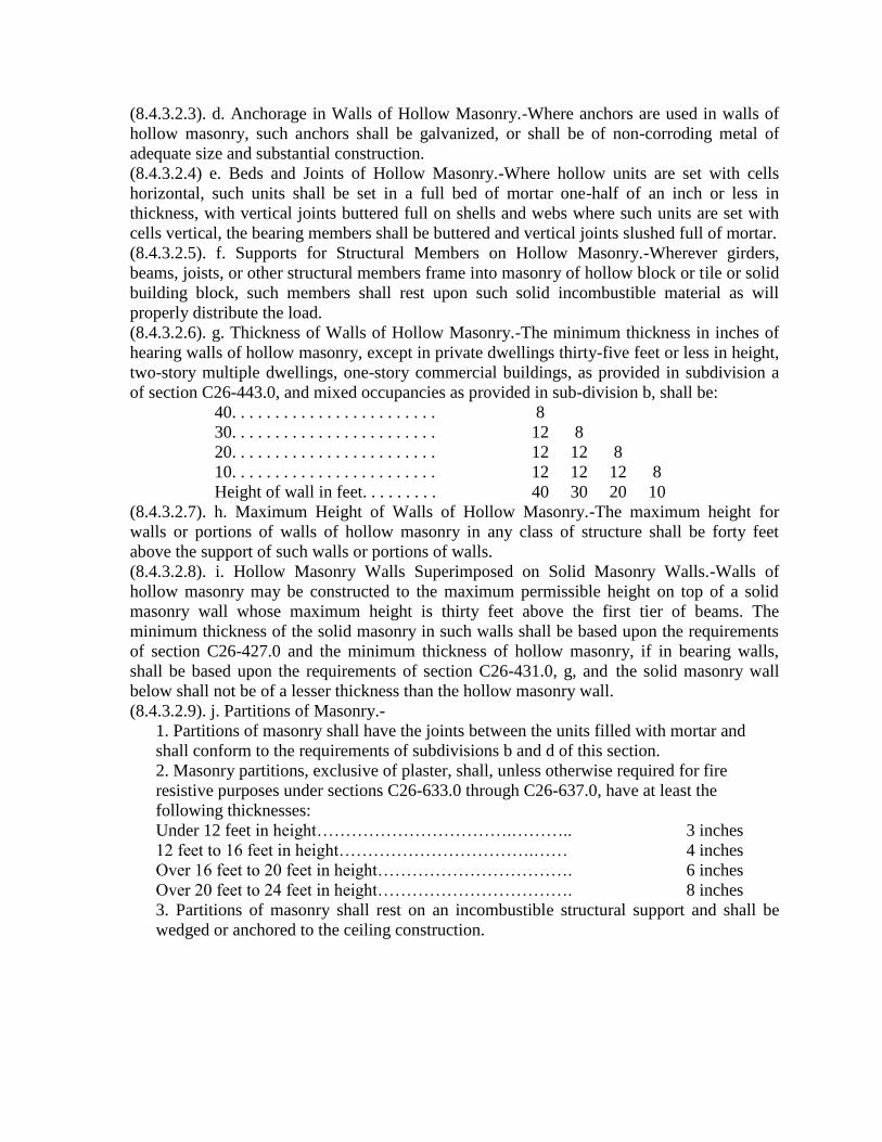
(8.4.3.2.3). d. Anchorage in Walls of Hollow Masonry.-Where anchors are used in walls of
hollow masonry, such anchors shall be galvanized, or shall be of non-corroding metal of
adequate size and substantial construction.
(8.4.3.2.4) e. Beds and Joints of Hollow Masonry.-Where hollow units are set with cells
horizontal, such units shall be set in a full bed of mortar one-half of an inch or less in
thickness, with vertical joints buttered full on shells and webs where such units are set with
cells vertical, the bearing members shall be buttered and vertical joints slushed full of mortar.
(8.4.3.2.5). f. Supports for Structural Members on Hollow Masonry.-Wherever girders,
beams, joists, or other structural members frame into masonry of hollow block or tile or solid
building block, such members shall rest upon such solid incombustible material as will
properly distribute the load.
(8.4.3.2.6). g. Thickness of Walls of Hollow Masonry.-The minimum thickness in inches of
hearing walls of hollow masonry, except in private dwellings thirty-five feet or less in height,
two-story multiple dwellings, one-story commercial buildings, as provided in subdivision a
of section C26-443.0, and mixed occupancies as provided in sub-division b, shall be:
40. . . . . . . . . . . . . . . . . . . . . . . . 8
30. . . . . . . . . . . . . . . . . . . . . . . . 12 8
20. . . . . . . . . . . . . . . . . . . . . . . . 12 12 8
10. . . . . . . . . . . . . . . . . . . . . . . . 12 12 12 8
Height of wall in feet. . . . . . . . . 40 30 20 10
(8.4.3.2.7). h. Maximum Height of Walls of Hollow Masonry.-The maximum height for
walls or portions of walls of hollow masonry in any class of structure shall be forty feet
above the support of such walls or portions of walls.
(8.4.3.2.8). i. Hollow Masonry Walls Superimposed on Solid Masonry Walls.-Walls of
hollow masonry may be constructed to the maximum permissible height on top of a solid
masonry wall whose maximum height is thirty feet above the first tier of beams. The
minimum thickness of the solid masonry in such walls shall be based upon the requirements
of section C26-427.0 and the minimum thickness of hollow masonry, if in bearing walls,
shall be based upon the requirements of section C26-431.0, g, and the solid masonry wall
below shall not be of a lesser thickness than the hollow masonry wall.
(8.4.3.2.9). j. Partitions of Masonry.-
1. Partitions of masonry shall have the joints between the units filled with mortar and
shall conform to the requirements of subdivisions b and d of this section.
2. Masonry partitions, exclusive of plaster, shall, unless otherwise required for fire
resistive purposes under sections C26-633.0 through C26-637.0, have at least the
following thicknesses:
Under 12 feet in height…………………………….……….. 3 inches
12 feet to 16 feet in height…………………………….…… 4 inches
Over 16 feet to 20 feet in height……………………………. 6 inches
Over 20 feet to 24 feet in height……………………………. 8 inches
3. Partitions of masonry shall rest on an incombustible structural support and shall be
wedged or anchored to the ceiling construction.

GROUP 4
Plain Concrete
(8.4.4). §C26-432.0 Plain Concrete.-The general requirements for plain concrete masonry
poured in place, as to workmanship, bond, anchors, forms, tests, construction details and
miscellaneous provisions shall be the same as the requirements prescribed in sections C26-
1455.0 through C26-1556.0, except that wall thickness of concrete masonry may be two inches
less than those required in Section C26-427.0 and subdivision a of Section C26-443.0, but all
such walls shall be at least eight inches thick, except that exterior panel walls of plain concrete
masonry shall be at least six inches thick and shall be provided with proper temperature
reinforcement.
GROUP 5
Stone Masonry
(8.4.5.1). §C26-433.0 Construction Requirements for Stone Masonry.-Stone masonry shall
meet the requirements of sections C26-416.0 through C26-421.0, and of section C26-426.0,
except that anchors for stone masonry in bearing walls shall be at least three feet long and at least
one-quarter of an inch by two inches in section.
(8.4.5.2). §C26-434.0 Beds and Joints of Stone Masonry.-Stone in bearing masonry shall be
laid in cement or cement-time mortar and all spaces and joints shall be thoroughly filled, except
as provided in section C26-314.0.
(8.4.5.3). §C26-435.0 Ashlar Masonry.-Walls of ashlar masonry having sawed, dressed or
squared beds shall be of the same thickness as that required in section C26-427.0. Bond stones
uniformly distributed shall be provided which shall have all area equivalent to at least sixteen
percent of the face area of the walls.
(8.4.5.4). §C26-436.0 Rubble Stone Masonry.-The wall thickness of rubble stone masonry shall
be at least four inches greater than the thickness required by section C26-427.0, except as
provided in subdivision a of section C26-443.0. Rubble stone masonry twenty-four inches or less
in thickness shall have bond stones with a maximum spacing of three feet vertically and
horizontally and if such masonry is of a greater thickness than twenty-four inches, such masonry
shall have one bond stone for each six square feet of wall surface on both sides.
GROUP 6
Veneered Walls
(8.4.6.1). §C26-437.0 Anchorage for Veneered Masonry Walls.-When masonry walls are
veneered with brick, architectural terra cotta, stone or other masonry, the material shall be
securely tied into the backing with the equivalent of the following minimum anchorage
requirements:
(8.4.6.1.1). 1. For anchorage of brick veneering on masonry, one substantial non-corroding
metal wall tie for each three hundred square inches of wall surface.
(8.4.6.1.2). 2. For anchorage of architectural terra cotta and other moulded units on masonry,
one non-corroding metal anchor at least equal to five-sixteenths of an inch, round or one-
eighth of an inch by three-quarters of an inch flat in sectional area to each piece and two or
more such anchors to all pieces over eighteen inches in length or more than three hundred
square inches in superficial area, except where such architectural terra cotta facing is bonded
and completely filled with the brick backing.

(8.4.6.1.3). 3. For anchorage of stone veneering on masonry, one non-corroding anchor at
least three-sixteenths of an inch by one inch flat, or its equivalent in cross-sectional area, to
each piece over one-half of a square foot in face area and at least two anchors to all pieces
over twenty-four inches in length or more than four hundred square inches in superficial area.
(8.4.6.2). §C26-438.0 Thickness and Height of Veneered Walls.-In all cases the veneering
shall be excluded in calculating the bearing wall thickness and the required thickness of the wall.
The maximum height of veneering on walls, other than panel or enclosure walls, shall be forty
feet above the foundations.
(8.4.6.3). §C26-439.0 Veneered Wood Frame Structures.-
a. Wood frame structures may be veneered with masonry laid up in cement or cement-lime
mortar. Such veneer shall be anchored to the frame by non-corroding metal ties equivalent to
the following minimum requirements:
(8.4.6.3.1). 1. For anchorage of brick veneer on frame structures, one wall tie to everyone
hundred sixty square inches of wall area.
(8.4.6.3.2). 2. For anchorage of stone, architectural terra cotta and other moulded units on
frame structures, one spike anchor or two wall ties to every two hundred sixty square
inches of wall area.
(8.4.6.3.3). b. It shall be unlawful to use such veneer on frame structures above a maximum
height of thirty-five feet above the foundation; it shall be unlawful also, to use such veneer
on structures having more than two stories and a gable. The veneer shall be directly
supported on the foundation.
(8.4.6.3.4). c. Frame structures veneered with masonry shall be considered to be in a different
class from masonry structures. It shall be unlawful to attribute any structural strength to the
veneer.
GROUP 7
Faced Walls
(8.4.7). §C26-440.0 Faced Walls.-
a. Faced walls shall be of at least the thickness required for masonry walls of the material
forming the backing. Facings of brick or solid structural units shall be bonded into the
backing with headers, or stretchers at least four inches thicker than the facing, the equivalent
of one-sixth of the area of wall. Dressed stone facings shall be bonded to the backing with the
equivalent of approximately one-fifth of the superficial area in bond stone at least four inches
thicker than the facing, in addition to which, every stone other than bond stone shall be
anchored to the backing with at least one non-corroding metal anchor, at least three-
sixteenths of an inch by one inch, or the equivalent, in cross-sectional area. In the case of
plain coursed ashlar the bond stone shall occur at least as every alternate stone in every third
course.
b. In the case of random ashlar, range work or other jointing schemes where the more
frequently spaced smaller units are used for bond stone, the metal anchors may be omitted,
provided the superficial area of the bond stone is at least equal to that required for brick
facing, one-sixth the area of the wall.
c. When faced walls are built of different materials, the minimum thickness shall be that
required for masonry walls built entirely of the material having the lower compressive
strength.

d. The height of a single course in faced walls shall, in all cases, except for pilaster and
spandrel facing stone, be at most ten times the thickness of the facing material.
e. When facing is used, such facing shall not be figured in the strength of the wall unless such
facing is at least four inches in thickness or at least the normal thickness of an average brick.
f. For private dwellings and multiple dwellings not in excess of two stories, and for one-story
commercial buildings, faced walls with 4 inches of brick and 4 inches of hollow block may
be used with header courses every 7th course. This shall apply to residence buildings only,
which are not in excess of two stories or 20 feet in height of the wall and commercial
buildings not in excess of one story or 13 feet in height of the wall.
GROUP 8
Party and Fire Walls
(8.4.8.1). §C26-441.0 Party Walls.-
a. Party walls may be of any type of masonry provided for herein and shall comply with all
requirements for bearing walls. Party walls which function also as fire walls shall, in
addition, conform to the requirements of section C26-631.0 and of section C26-632.0.
b. It shall be unlawful to load any party wall on either side to more than fifty percent of its
allowable loading.
(8.4.8.2). §C26-442.0 Fire Walls.-Fire walls of masonry shall meet the material, thickness and
construction requirements of section C26-631.0 and of section C26-632.0.
GROUP 9
Special Forms of Bearing, Non-Bearing Walls and Other Masonry Construction
(8.4.9.1). C26-443.0 Bearing Walls for Private Dwellings, Two-story Multiple Dwellings and
One-story Commercial Buildings.-
a. The minimum thickness in inches of walls for private dwellings thirty-five feet or less in
height, except as provided in subdivision c of this section, two-story multiple dwellings and
one-story commercial buildings not more than thirteen feet in height shall be:
Solid Masonry Solid
Structural Units
Hollow Masonry and
Hollow Walls of Solid
Structural Units Rubble Stone Masonry
3 8 … … 8 … … 16 … …
2 8 8 … 8 8 … 16 … …
1 8 8 8 10 8 8 16 16 16
Stories 3 2 1 3 2 1 3 2 1
b. Mixed occupancies.-In three-story structures having a maximum width of twenty-five feet,
where the first story is used for commercial purposes and the upper stories for residence
purposes, the minimum thickness of bearing walls shall be eight inches.
c. The minimum thickness of bearing walls of private dwellings not more than one story in
height shall be five and one half inches, provided the height of the wall does not exceed nine
feet to the eaves or fifteen feet to the peak of gables and provided such walls are constructed
of solid masonry.
(8.4.9.2). §C26-444.0 Parapet Walls.-
a. In all structures exceeding twenty-two feet in height, exterior walls of masonry, shall have
parapet walls carried 3 feet 6 inches above the roof with the following exceptions:

1. One or two family residence structures with overhanging roofs or where roofs are
finished with cornices or gutters, when access to roof is limited to a scuttle and vertical
ladder.
2. Detached structures with overhanging roofs or cornices where metal railings not less
than 3 feet 6 inches in height are provided.
3. Exterior walls of fireproof buildings having metal railings not less than 3 feet 6 inches
in height.
All metal railings shall be of a type which will prevent children crawling through or
climbing over same and shall be provided with any further maximum protection as required
by the commissioner.
Where roofs are used for recreational purposes, wire caging at least 10 feet high,
structurally supported, shall be constructed.
Where ball games are played on roofs, a continuous wire roofing shall be constructed.
b. Parapet walls shall be of the same thickness as the wall below, except that in all cases, the
thickness required shall be at most twelve inches.
c. Residence structures shall have parapet walls carried at least two feet above the roof, with
the following exceptions:
1. Parapet walls between structures of the same height and forty feet or less in height
shall extend at least eight inches above the roof;
2. Party walls in structures the roofs of which pitch at an angle of twenty degrees or more
from the horizontal may stop at the top of the roof boards, provided, no combustible
material passes through the wall and the junction of roof and wall is thoroughly fire-
stopped;
3. Fire partition walls for the purpose of subdividing non-fireproof residence structures
shall be carried to the top of the roof boards be thoroughly grouted with cement mortar
and fire-stopped, or carried through the roof.
d. When parapet walls function as parts of party walls, or fire walls, such parapet wall shall
conform to the requirements for such walls.
e. All parapet walls shall be coped with incombustible and durable material.
(8.4.9.3). §C26-445.0 Non-bearing Masonry Walls.-The minimum thickness of non-bearing
masonry walls, except as provided in section C26-428.0 may be four inches less than the
thickness required for bearing walls, but any such wall shall be at least eight inches thick, except
as provided in Section C26-446.0.
(8.4.9.4). §C26-446.0 Panel, Apron and Spandrel Walls.- a. Panel walls shall be constructed of incombustible materials or assemblies of materials
having a fire resistive rating of at least two hours in class 1 structures, and one hour in class
2, 3 and 6 structures except as otherwise provided in Sections C26-240.0, C26-241.0 and
C26-244.0. Panel walls shall be so designed as to transmit into the frame an assumed wind
pressure of thirty pounds per square foot of exposed surface applied in either direction
without undue deflection and shall be secured to the frame in a permanent and weatherproof
manner.
b. Panel walls shall be bonded or otherwise so secured to the structure as to furnish adequate
lateral support to the wall.
(8.4.9.5). §C26-447.0 Enclosure Walls.-Enclosure walls shall meet all the requirements of
height, thickness and type of construction prescribed for bearing walls.
(8.4.9.6). §C26-448.0 Masonry Curtain Walls.-
a. Curtain walls of solid masonry shall be at least eight inches thick for the uppermost
thirteen feet and at least twelve inches thick for the next fifty-two feet or fraction thereof
below and shall be increased four inches in thickness for each succeeding sixty feet or
fraction thereof below.
b. When masonry curtain walls are built of masonry other than solid masonry, such walls
shall be at least ten inches thick for the first thirteen feet, twelve inches thick for the next
lower thirty-nine feet and shall be increased in thickness four inches for each thirty-nine feet
or fraction thereof next below, provided that the maximum horizontal distance between
lateral supports shall be twenty feet. When the distance between the lateral supports exceed
twenty feet, the thicknesses of all walls specified in this section shall be increased four inches
for each additional ten feet or fraction thereof between lateral supports. Curtain walls of
hollow masonry twelve inches or more in thickness shall be made of at least two bonded
units.
(8.4.9.7). §C26-449.0 Furring.-Masonry materials used as furring shall be excluded in
calculating the required wall thickness, and such furring shall be considered to lack any
structural value.
(8.4.9.8). §C26-450.0 Chases and Recesses.-
a. It shall he unlawful to have chases in eight-inch walls or within the required area of any
pier. The maximum depth of any permitted chase in any wall shall be one-third of the wall
thickness. The maximum length of any horizontal chase without suitable structural support
shall be four feet, and the maximum horizontal projection of any diagonal chase shall be four
feet.
b. Recesses shall have at least eight inches of material at the back.
c. The maximum aggregate area of recesses and chases in any wall shall be one-quarter of the
whole area of the face of the wall in any story, except that for stairs, elevators and
dumbwaiters, the walls, including foundation walls behind such facilities, may be reduced to
twelve inches.
d. It shall be unlawful to have chases or recesses in fire walls, fire partitions and in fire
protection of structural members which chases or recesses would reduce the thickness below
the minimum specified in this title.
e. Chases and recesses may be built into hollow walls and walls constructed of hollow block
or tile, but it shall be unlawful to cut chases or recesses in walls of these types of
construction.
(8.4.9.9). §C26-451.0 Corbelling.-It shall be unlawful to corbel walls less than twelve inches
thick, except for fire-stopping. Corbelling of hollow masonry shall be supported by at least the
equivalent of one full course of the hollow masonry in solid masonry. All corbelling shall be
done with solid masonry. The maximum horizontal projection in any corbel shall be one inch for
each two inches of vertical projection, and in all cases the total projection of the corbelling shall
be one-third or less of the minimum thickness of the wall to be corbelled.
(8.4.9.10) §C26-452.0 Cornices.-The center of gravity of all projecting or moulded cornices,
unless such cornices are surmounted by masonry, shall be within the middle third of the wall
below, unless satisfactory structural support is provided. Projecting cornices of stone or terra
cotta shall have beds in the wall at least one inch greater in depth than their maximum projection,
unless such beds are anchored to the structure. Moulded projecting courses shall have at least

four-sevenths of their cubical contents inside the wall, unless such courses are anchored to and
supported by the structure.
(8.4.9.11). §C26-453.0 Use of Existing Walls.-A wall, erected before January first, nineteen
hundred thirty-eight, whose thickness at the time of its erection was in accordance with law, but
the thickness of which does not conform to the requirements of this title, may be used without
change, if such wall is in good condition, in structures erected or altered after January first,
nineteen hundred thirty-eight provided the stresses in the masonry are within the working
stresses prescribed by sections C26-355.0 through C20-362.0, and that the height of such wall is
increased only in so far as may be necessary to make the height uniform.
(8.4.9.12). §C26-454.0 Lining of Walls.-If it is desired to increase the height of any wall,
erected before January first, nineteen hundred thirty-eight, which is thinner than required by this
title, such wall shall be reinforced by a lining of solid masonry so that the combined thickness
shall be at least four inches more than is required for a new wall corresponding with the total
height of the wall when increased in height; provided that it shall be unlawful to use such lining
to a greater height than forty feet or to increase the height of such wall to exceed seventy-five
feet. Such lining shall be supported on proper foundations and shall be at least eight inches in
thickness and so anchored to the old wall as to make the reconstructed wall act as a unit. Where
any lining is to be built against an old wall, such wall shall be first cleaned of plaster or other
coatings. Walls to be lined shall be in good condition and the approval of the superintendent
shall be necessary before the work begins.
(8.4.9.13). §C26-455.0 Unsupported Height of Masonry Walls During Construction.-The
maximum unsupported height of any masonry wall during the period of construction shall be two
stories or twenty-six feet, unless satisfactory support is provided and specific approval of the
superintendent obtained, except when walls are carried separately by structural members on each
story.
(8.4.9.14). §C26-456.0 Stairway, Elevator and Similar Enclosures.- a. Enclosing walls of interior shafts, if non-bearing, shall meet the requirements for non-
bearing walls, and if such walls are bearing, they shall meet the requirements for bearing
walls, except as provided in section C26-428.0, and where such enclosing walls are
supported at each story on structural members.
b. Where the enclosures are supported by structural members at each story such enclosures
shall meet the requirements of sections C26-638.0 through C26-647.0 and of sections
C26·660.0 through C26-665.0.
GROUP 10
Plastering
(8.4.10.1). §C26-457.0 General Plastering Requirements.-Plastering shall be performed in
accordance with the requirements of sections sixty through sixty-eight of the general city law and
with the requirements of this title.
(8.4.10.2). §C26-458.0 Combustible Lath.-
a. It shall be unlawful in the case of structures exceeding three stories in height, to apply
combustible lath on wood studs more than two stories in advance of the scratch coat
plastering.
b. It shall be unlawful to run combustible lath through from room to room.
c. Wood lath shall be between one and one-quarter and one and five-eighths inches wide and
between five-sixteenths and three-eighths of an inch thick.
d. The quality of wood lath shall permit use without waste and shall be of the grade of at least
No.2 lath with small and loose knots wane and other defects limited.
e. Wood lath and other combustible lath shall be solidly nailed at every bearing.
f. It shall be unlawful to apply vertical or diagonal lathing. Ceiling lath shall run in one
direction only.
g. The joints on walls and ceilings shall be broken at least every eighth lath in the case of
wood lath, and as required by the rules of the board in the case of other combustible lath.
(8.4.10.3). §C26-459.0 Metal Lath.-
a. Metal lath shall weigh at least three pounds per square yard and shall be galvanized or
painted for interior use and either galvanized or of non-corroding metal for exterior use.
Expanded metal reinforcing with integral flame-proof paper backing shall weigh not less than
2.2 pounds per square yard exclusive of paper and the maximum mesh opening shall be 11/8
inches by 2½ inches from center point to center point of the bridges and shall be expanded
from no lighter metal than 23 gauge.
b. Woven lath with a maximum mesh opening of one-half inch may be made of wire as fine
as No. 20 steel wire gauge, and shall be painted or galvanized.
c. Welded lath shall be made of galvanized wire of No. 16 steel wire gauge, or larger, with a
maximum mesh opening of two by two inches, or equal weight per yard if mesh is finer, but
in any case at least No. 20 steel wire gauge.
d. Expanded sheet metal and wire lath shall be of a type suitable to form a key sufficient to
retain the plaster firmly.
e. Metal lath shall be lapped at least one inch on abutting edges. Where metal lath finishes
against masonry walls, the lath shall be extended to at least three inches on the surface of
such walls and securely fastened.
f. Metal lath shall be kept at least three-eighths of an inch away from sheathing or other solid
surfaces.
g. Metal lath without stiffeners shall be tied or laced to metal supports at least every six
inches with No. 18 steel wire gauge galvanized, soft annealed wire, and all lath with
stiffeners at least at eight inch intervals; at lap joints horizontally between the studs, a similar
tie shall be provided. The ends of all tie wires shall be twisted tight with a double turn and
bent flush with the face of the lath.
h. Metal lath fastened to wood furring or studs shall be attached at least at six-inch intervals
with four-penny nails or one-inch roofing nails or No. 14 steel wire gauge wire staples; and
two wood joists by at least six-penny nails, one and one-quarter-inch roofing nails, or one-
inch No. 14 steel wire gauge wire staples. Laps between the studs or joists shall be securely
tied or laced as required under the preceding paragraph. Stiffened metal lath on wood studs
or joists shall be nailed or stapled at least at eight-inch intervals, and the laps between studs
similarly tied or laced.
(8.4.10.4). §C26-460.0 Furring and Studding for Metal Lath and Plaster Partitions and
Ceilings.-
a. Furring or studding for metal lath and plaster partitions or ceilings shall have a maximum
spacing for varying weights of lath as given in the following schedule:

Maximum Spacing of Studding or Furring in Inches
Nailed-On Work
Types of metal Lath
Walls and
Partitions Ceilings
Expanded metal:
3.4 pounds per square yard, plastered one side 16 16
Flat rib metal lath:
2.75 pounds per square yard, plastered one side 16 16
3.4 pounds per square yard, plastered one side 19 19
Three-eighth-inch rib metal lath:
3.4 pounds per square yard; plastered one side 24 24
Bar ribbed expanded metal lath:
3.4 pounds per square yard; plastered one side 24 24
4.0 pounds per square yard; plastered one side 24 24
Sheet lath:
4.5 pounds per square yard, plastered one side 24 24
Tied-On Work
Solid
partitions
Hollow and
double
partitions
Suspended
ceilings
Expanded metal lath:
3.4 pounds per square yard 16 12 12
3.4 pounds per square yard 16 13½ 13½
Flat rib metal lath:
2.75 pounds per square yard 16 16 12
3.4 pounds per square yard 19 19 19
Three-eighth inch rib metal lath
3.4 pounds per square yard 24 24 24
4.0 pounds per square yard 24 24 24
Bar rib expanded metal lath:
3.4 pounds per square yard 24 24 24
4.0 pounds per square yard 24 24 24
Sheet lath:
4.5 pounds per square yard 24 24 19
Woven-wire lath:
No. 20 steel wire gage, 1/2-inch mesh plastered
on one or two sides 12 12 12
No. 18 steel wire gage, 1/2-inch mesh plastered
on one or two sides 16 16 16
No. 19 steel wire gage, 2½ mesh to inch, plastered
on one or two sides 16 16 16
No. 16 steel wire gage, 2-inch mesh, plastered on
one side 12 16 12
No. 20 steel wire gage, ½-inch mesh, V-stiffened 8
inches center mesh, plastered on one side 16 16 12
No. 16 steel wire gage, 2-inch mesh, galvanized
welded wire fabric with integral backing and
horizontal stiffening members spaced not more
than five inches on centers, plastered on one side 16 16 16
b. Furring or studding for partitions plastered on one or two sides shall consist of channels of
the following sizes, or angles, tees or flats of equivalent sectional area:
Maximum height in feet
Minimum thickness in inches
Of partition Of channels

12 2 ¾
14 2 1
14 2¼ ¾
16 2¼ 1
18 2½ 1
c. The furring or studs shall be securely fastened on top and bottom and, wherever necessary,
shall be braced at intermediate points.
d. In the case of heavy ornamental ceiling work, special provision shall be made to sustain
the load.
(As amended by Local Law 53 of 1948 in effect July 1, 1948.)
§C26-461.0 Suspended ceilings.-Suspended ceilings shall comply with the following minimum
requirements as to material and construction. When required by the superintendent, details of the
method of supporting suspended ceilings shall be submitted to the department for approval.
1. Hangers for suspended ceilings.-Hangers for suspended ceilings shall comply with the
following requirements:
(a) Class 1-Fireproof structures:
(1) Hangers for suspended ceilings in new fireproof structures shall be placed to line
in either direction with a maximum spacing of five feet on centers. Such hangers shall
extend through the floor arches and shall be formed of two pieces of one-inch hot
rolled channels, weighing not less than six-tenths of a pound per linear foot, or three-
sixteenths by one inch flat bars, at least seven inches long, bolted, riveted or welded
together to form a tee and punched to receive three-eighths inch diameter bolts at the
lower end and coated with asphaltum. Other types of hangers may be used if
approved by the board as corrosion-resistant, durable, and having strength and
rigidity adequate for ceiling hangers. Where ceilings weigh less than four pounds per
square foot and are constructed as dry ceilings without plastering, flat bars used as
hangers may be one-eighth inch by one inch in size.
When hangers are installed for suspended ceilings in existing fireproof structures,
they shall be attached directly by steel bridging in each bay anchored into the haunch
of the beams supporting the floor or roof construction above, or as approved by the
superintendent; however, the steel bridging in alternate bays may be replaced by a
hanger, one inch by three-sixteenths of an inch, hooked over the reinforcing wire or
bar of the floor or roof construction above. Such bridging shall be of sufficient
strength to safely support the ceiling and be anchored into the haunches of the beams
at least two and one-half inches on each side.
(Subd. (1) of Subd. 1(a) amended by Local Law 103 of 1955 in effect November 4,
1955.)
(b) Class 2 Fire protected structures. Hangers for suspended ceilings in class 2 fire
protected structures shall be installed in conformity with requirements for class 1
structures wherever possible or as approved by the superintendent.
(c) Hangers for suspended ceilings in new non-fireproof construction, except where the
ceilings are constructed in conformance with paragraph 2 (d) of this section, shall be flat
metal bars at least one-inch by three-sixteenths of an inch placed not more than five feet
on centers, and be bent around three sides of the supporting joist and nailed to the joist. In
new non-fireproof construction, hangers may also be attached to the joint by means of
two (2) one-quarter-inch diameter through bolts which shall be at least two inches above
the bottom of the joist. In existing non-fireproof construction, except where the ceilings

are constructed in conformance with paragraph (d) of subdivision two of this section,
where it is impractical to use bent hangers or through bolts as described above, each
hanger shall be nailed to the joist with two (2) two and one-quarter inch barbed anchor
nails (over-all dimension), which are one-quarter-inch in diameter, with oval head, which
shall be at least two inches above the bottom of the joist. Purlins in which ceiling is
attached shall be placed not in excess of five feet on centers. (Par. (c) of subd. 1 as
amended by Local Law 19 of 1951 in effect January 30, 1951.)
2. Purlins for suspended ceilings.
(a) Purlins shall be either hot or cold rolled steel channels or angles and the maximum
spans and spacings for the respective weights and materials shall be as shown in Table 1,
except where the ceilings are constructed in conformance with paragraph 2 (d) of this
section. Table 1
Maximum spacing in both
directions Size purlins required Weight per foot
5 feet 1½-inch hot rolled channel 1.05 pounds
5 feet 1½-inch by 1½-inch by 1/8-inch angle 1.23 pounds
4 feet 11/2-inch hot rolled channel 0.85 pounds
3 feet 1½-inch cold rolled channel 0.475 pounds
Purlins shall be bolted to each hanger with three-eighths (3/8) inch diameter stove bolts or
equivalent.
(b) When purlins are attached to beams, girders or trusses, approved anchors or clips shall
be used. All purlins not supported directly by hangers shall be fastened with approved
metal clips to cross pieces at most four feet on centers.
(c) Purlins for lightweight ceilings. For lightweight ceilings weighing four (4) pounds or
less per square foot, constructed dry without plastering, purlins may be one and one-half
(1½) inch cold rolled channel weighing 0.475 pounds per linear foot spaced four (4) feet
or less on center. (As amended by section 2. of Local Law 16 of 1954 in effect April 26,
1954.)
(d) In other than class 1 and class 2 structures, and except for ceilings in special
occupancy structures, wood purlins may be used to support suspended ceilings. They
shall be adequate to support the ceilings, with stresses not exceeding the limitations of
section C26-270.0, and shall be at least two inches by three inches, nominal size. They
shall be straight, in as long lengths as practical, and shall be spaced not more than sixteen
inches apart center to center. The wood purlins when constructed in conformance with
this paragraph may be hung by galvanized steel hangers, not smaller than number
fourteen Birmingham Wire Gage (.083 inch) thick by one inch wide, with holes not more
than one-quarter inch in diameter, located to receive the nails, and such hangers shall be
spaced not more than five feet apart along each purlin. The hangers shall be nailed to
each supporting beam and purlin by at least two galvanized roofing nails, not less than
one and three-quarter inches long and number eleven United States Steel Wire Gage
(.1205 inch) in thickness. Cross braces at least two inches by three inches in size shall be
provided across the top of the purlins, not more than five feet apart, securely nailed to
each purlin. Sufficient stiffeners shall be provided between the supporting beams and the
purlins to provide rigidity for the application of lath and plaster. Such stiffeners may be
of wood and wood stiffeners left in place shall not be closer than eight feet apart along
each purlin. When this type of construction is used, cross-furring shall not be required.

Where wood purlins are used as provided herein, the space between the ceiling and the
floor or roof above shall be divided into areas of two thousand square feet or less by
firestops extending from the ceiling to the underside of the floor or roof boards above.
Firestopping shall consist of one-half inch plaster boards on both sides of two inch by
three inch, or larger, studs, spaced not more than sixteen inches apart, with tight joints, or
any construction approved for a one hour partition, securely fastened in place.
Subd. 2 as amended Local Law 19 of 1951 in effect January 30, 1951.)
3. Cross furring for suspended ceilings.-For purlins spaced as shown in table 1 above, the
maximum size and spacing of the cross furring shall be as shown in table 2. (This cross
furring table applies to plastered ceilings varying in weight from six to twelve pounds per
square foot depending upon the type of plaster used.) Table 2
Maximum span
of cross-furring Size Weight per foot
Maximum
Spacing
Attachment of
cross furring to
purlin
5 feet 1-inch chan. 0.600# 13½ inches No. 8 gage
hairpin wire
clips, 2 strands
of no. 16 gage
galvanized
annealed wire or
equivalent.
4 feet 1-inch chan. 0.410# 13½ inches
3 feet ¾-inch chan. 0.300# 13½ inches
4. Cross furring for lightweight ceilings. When ceilings attached to cross furring weigh less
than four (4) pounds per square foot and are constructed dry without plastering, hangers shall
be not more than five (5) feet center to center supporting purlins, and cross furring shall be at
least ¾-inch cold rolled channels spaced not more than sixteen (16) inches center to center;
except that the board may approve, in a specific case, spacing of cross furring in excess of
sixteen (16) inches on centers but not to exceed twenty-four (24) inches on center. (As
amended by section 3. of Local Law 16 of 1954 in effect April 26, 1954.)
§C26-461.1 Plastic light diffusers.-
a. Plastic light diffusers suspended below and associated with lighting fixtures shall not be
construed as suspended ceilings.
b. Plastic diffuser shall be a special compound plastic developed for light diffusion, with a
fire rating classification as self-extinguishing when tested in conformance with A.S.T.M.
standard method of test D635-44 for plastic materials of .050 thickness or greater, and
A.S.T.M. standard method of test D568-43 for plastic materials of less than .050 thickness.
c. “Plastic light diffusers shall be adequately supported by frames and hangers of
incombustible material secured to the ceiling, floor or roof construction above. The
maximum dimension of any single sheet of plastic shall not exceed five feet for plastic
material exceeding .050 inches in thickness and shall not exceed twenty-five feet for plastic
material of .050 inches thickness or less. The area of a single sheet or such thinner material
shall not exceed seventy-five square feet. Plastic light diffusers shall not be constructed in
any required stair enclosure, in public hallways, required exit corridors or exit passageways.”
d. The plastic diffusers shall be approved by the board of standards and appeals. (As added by
Local Law 191 of 1953 in effect December 31, 1953.)
(8.4.10.6). §C26-462.0 Gypsum lath and other solid plaster bases.-
l. Gypsum lath. Gypsum lath shall comply with the standard specifications of the ASTM, D,
C-37-42, and shall be not less than three-eighths inch thick.
Gypsum lath shall be securely nailed to wood supports spaced not to exceed sixteen
inches on center at intervals not to exceed four inches on ceilings and five and one-half
inches on walls or partitions with thirteen gage, one and one-eighth inch long, nineteen-sixty-
fourths inch flat head, blue nails. The nails shall be driven with the underside of the head
flush with the face of the lath and shall not be closer than three-eighths inch from edges or
ends. There shall be five nails per lath per support on ceilings and four nails per lath per
support on walls or partitions. Gypsum lath shall be applied with the face side out and with
the long dimensions at right angles to the framing members. Gypsum lath shall be attached to
horizontal or vertical incombustible supports by means of special attachment devices
approved by the board. The joints shall be broken at every other board on walls and at right
angles to the furring on ceilings.
2. Other solid plaster bases.-Other types of solid plaster bases shall be approved in
accordance with the rules of the board and shall be nailed directly to all wood studding or
furring with one and one-eighth inch wire nails of at least no. 13 steel wire gage. Such nails
shall have flat three-eighths inch heads. The maximum space between nails for walls shall be
six inches; the maximum space between nails for ceilings shall be four inches. Joints shall be
broken at every other board on walls and at right angles to the furring on ceilings.
(As amended by Local Law 122 of 1952 in effect October 20, 1952.)
(8.4.10.7). §C26-463.0 Quality of Plastering Materials.-Gypsum, lime cement, sand perlite,
vermiculite and mortar shall comply with the requirements of section C26-312.0.
(8.4.10.8). §C26-464.0 Proportioning and Application of Plaster.-Plaster shall consist of lime,
sand, hair or fibre, or gypsum plaster, sand, vermiculite, perlite or fibre.
The hair binder shall be water-soaked, well beaten, clean, long winter hair. Fibre shall he
approved by the board.
Plaster shall be applied in three coats, the scratch coat, the brown coat, and the finish coat,
except as otherwise provided in this section. No "laid-off" work on lath shall be permitted.
The scratch coat shall be applied first on all types of lath and shall be mixed in the
proportions of one part lime putty to two parts of sand by volume, or two cubic feet of sand,
perlite or vermiculite to not less than one hundred pounds of gypsum plaster.
The brown coat shall be applied second and shall be mixed in the proportions of one part of
lime putty to three parts of sand by volume, or three cubic feet of sand perlite or vermiculite to
not less than one hundred pounds of gypsum.
In lieu of the proportioning specified above for scratch and brown coats the proportions may
be 100 pounds gypsum neat plaster to not more than 250 pounds of sand or 20 cubic feet of
vermiculite or perlite, and provided such proportions are used for both scratch and brown coats.
The finish coat shall be applied over the brown coat and shall consist of lime putty and
gauging plaster or other finish approved by the board.
The scratch coat shall be applied to all lathed surfaces, and on walls and partitions such coats
shall be carried to the floor. The scratch coat shall be applied with sufficient pressure and
material to provide a proper key or bond and in all cases such coat shall be scratched vertically
and horizontally. Gypsum plaster only shall be used on gypsum plaster bases.
The scratch coat may be omitted when applying plaster directly to brick, clay or gypsum tile,
stone or concrete masonry.
The brown coat shall be applied over the scratch coat where used, and on all masonry
surfaces, and shall be carried to the floor. Where lime plaster is used, the brown coat shall be
applied a minimum of twelve hours after the application of the scratch coat. Where gypsum

plaster is used, the brown coat shall be applied a minimum of twelve hours after the application
of the scratch coat. The brown coat shall be brought out to grounds and straightened to a true
surface and left rough to receive the finish coat.
The finishing coat shall be applied after the second or brown coat has become set and about
dry.
A base coat for plastering on cement surfaces or on cinder or stone concrete shall be used and
shall be a specially prepared bond plaster base coat to which aggregate shall not be added, or a
specially prepared bonding finishing plaster approved by the board and applied in accordance
with such approval.
(8.4.10.9). §C26-465.0 Mixing of Plaster.-Where hard wall plaster is specified, such plaster
shall be received at the structure in the manufacturer's original package and shall be mixed and
applied in accordance with his specifications.
(8.4.10.10). §C26-466.0 Keene's Cement.-Keene's cement shall be approved by the board and
shall comply with the standard specifications of the A.S.T.M., D., C61-40 and shall be delivered
in the manufacturer's original package and shall be applied according to the manufacturer's
specifications.
(8.4.10.11). §C26-466.1 Vermiculite Plaster.-The particle size of vermiculite shall conform
with the requirements of the “standard specifications for inorganic aggregates for use in gypsum
plaster.” A.S.T.M., C. 35-59. The weight shall not be less than six nor more than ten pounds per
cubic foot as determined by measurements in a cubic foot box using the shoveling procedure as
outlined in the “standard method of test for unit weight of aggregate.”
(8.4.10.12). §C26-466.2 Perlite Plaster.-The particle size of perlite shall conform with the
requirements of the “standard specifications for sand for use in plaster.” A.S.T.M., C. 35-39,
except that the minimum percentage retained on a no. 100 (149 micron) sieve shalt be decreased
from 95% to 90%. The weight shall be not less than seven and one-half nor more than ten
pounds per cubic foot as determined by measurements in a cubic foot box using the shoveling
procedure as outlined in the “standard method of test for unit weight of aggregate,” A.S.T.M., C.
29-42.
(8.4.10.13). §C26-467.0 Plastering Notes.- a. Unpainted masonry surfaces which are to be plastered shall be thoroughly broomed off
before plastering is started. Where masonry surfaces exhibit high suction they shall be wet
down before plastering.
b. Concrete and cement surfaces which are to be plastered shall be cleaned of all dust and
loose particles. Where bond plaster basecoat is used, surfaces shall be washed with a ten
percent solution of muriatic acid and water and then with clean water to remove all traces of
the acid and roughened to provide a proper bond. Specially prepared bonding finishing
plaster approved by the board may be applied to smooth concrete and cement surfaces in
accordance with such approval.
c. When plastering is in progress and until such plastering has become thoroughly dry, the
structure shall be enclosed and heated if necessary to maintain a minimum temperature of
40°F.
d. It shall be unlawful to apply on the inner surface of an exterior masonry wall of a dwelling
structure, any materials which are not impervious to moisture except when such materials are
applied on furring of at least seven-eighths of an inch in thickness. A hollow wall of masonry
shall not be deemed a solid masonry wall for the purpose of this section.

All of Sub-Article 5, “Reinforced Concrete Construction.” (§C26-468.0 to §C26-509.0
inclusive) repealed December, 1962 and replaced by Article 19.
Sub-Article 6. Iron and Steel Construction
GROUP 1
Cast Iron
(8.6.1.1.1). §C26-510.0 Cast Iron Columns.-
a. Dimensions of Cast Iron Columns.-Cast iron columns shall have an outside diameter or
side of at least five inches, and their maximum unsupported length shall conform to the
requirements of section C26-367.0.
(8.6.1.1.2). b. Thickness of Metal in Cast Iron Column.-The thickness of metal shall be at
least one-twelfth the diameter or least dimension of cross-section, with a minimum thickness
of three-fourths of an inch. The core of columns above and below a joint shall be the same,
but where one column is supported by another of larger diameter, the core of the latter shall
be tapered down over a distance of at least six inches, or a joint plate shall be inserted of
sufficient strength to distribute the load. Wherever the core of a cast iron column has shifted
more than one-fourth the thickness of the shell, the thickness of the metal all around shall be
assumed equal to the thinnest part.
(8.6.1.1.3). c. Joints of Cast Iron Columns.-Cast iron columns shall be machine faced at the
end to a true surface perpendicular to the axis. They shall be bolted together with at least four
bolts, three-quarters of an inch or more in diameter, passing through the flanges, the bolts
being of sufficient length to allow the nuts to be screwed up tightly; and as each column is
placed in position, the bolts shall also be placed in position and the nuts shall be screwed up
tightly.
(8.6.1.1.4). d. Flanges of Cast Iron Columns.-Where cast iron columns rest one on top of
another, the top flange of the lower column shall project on all sides at least three inches
from the outer surfaces of the column, and the shape and dimensions of the bottom flange of
the upper column shall be the same as those of the top flange of the lower column, except
that when a column is placed on a lot line, the flanges on the side toward such lot may be
omitted, unless required for boltings. Flanges shall be at least one inch in thickness when
finished, and shall be reinforced by fillets and brackets.
(8.6.1.1.5). e. Bolt Holes in Cast Iron Columns.-All holes in cast iron columns shall be
drilled. The diameter of the holes shall be within the diameter of the bolts plus one-sixteenth
of an inch.
(8.6.1.1.6). f. Limitation on Use of Cast Iron Columns.-It shall be unlawful to use cast iron
columns in any case where the load is so eccentric as to cause tension in the cast iron or for
such parts of the structural frame of structures as are required to resist stress due to wind.
(8.6.1.1.7). g. Inspection of Cast Iron Columns.-A cast iron column shall be set in place only
after it has passed an inspection satisfactory to the superintendent. Wherever blowholes or
imperfections are found, which reduce the area of the cross-section at that point more than
ten percent, such columns shall be condemned. Columns cast without one open side or back,
shall have three-eighth-inch holes drilled in the shaft, to exhibit the thickness of the castings,
as may be required by the superintendent. Columns shall be inspected before painting.
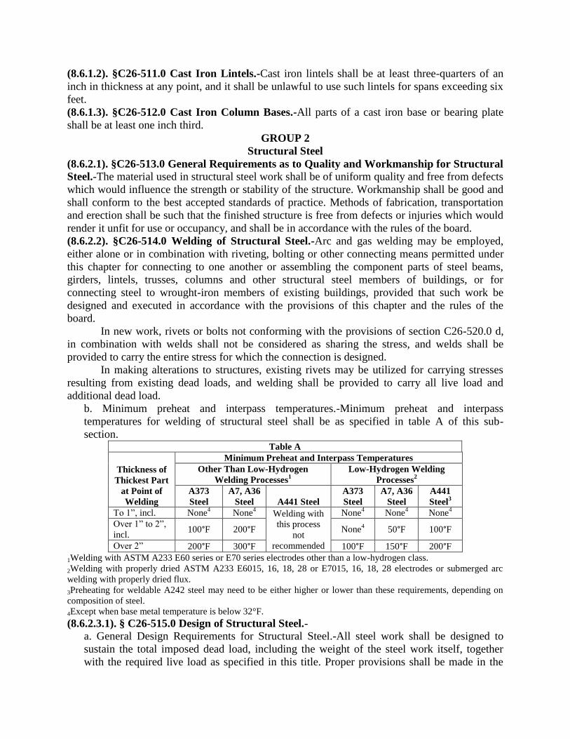
(8.6.1.2). §C26-511.0 Cast Iron Lintels.-Cast iron lintels shall be at least three-quarters of an
inch in thickness at any point, and it shall be unlawful to use such lintels for spans exceeding six
feet.
(8.6.1.3). §C26-512.0 Cast Iron Column Bases.-All parts of a cast iron base or bearing plate
shall be at least one inch third.
GROUP 2
Structural Steel
(8.6.2.1). §C26-513.0 General Requirements as to Quality and Workmanship for Structural
Steel.-The material used in structural steel work shall be of uniform quality and free from defects
which would influence the strength or stability of the structure. Workmanship shall be good and
shall conform to the best accepted standards of practice. Methods of fabrication, transportation
and erection shall be such that the finished structure is free from defects or injuries which would
render it unfit for use or occupancy, and shall be in accordance with the rules of the board.
(8.6.2.2). §C26-514.0 Welding of Structural Steel.-Arc and gas welding may be employed,
either alone or in combination with riveting, bolting or other connecting means permitted under
this chapter for connecting to one another or assembling the component parts of steel beams,
girders, lintels, trusses, columns and other structural steel members of buildings, or for
connecting steel to wrought-iron members of existing buildings, provided that such work be
designed and executed in accordance with the provisions of this chapter and the rules of the
board.
In new work, rivets or bolts not conforming with the provisions of section C26-520.0 d,
in combination with welds shall not be considered as sharing the stress, and welds shall be
provided to carry the entire stress for which the connection is designed.
In making alterations to structures, existing rivets may be utilized for carrying stresses
resulting from existing dead loads, and welding shall be provided to carry all live load and
additional dead load.
b. Minimum preheat and interpass temperatures.-Minimum preheat and interpass
temperatures for welding of structural steel shall be as specified in table A of this sub-
section. Table A
Thickness of
Thickest Part
at Point of
Welding
Minimum Preheat and Interpass Temperatures
Other Than Low-Hydrogen
Welding Processes1
Low-Hydrogen Welding
Processes2
A373
Steel
A7, A36
Steel A441 Steel
A373
Steel
A7, A36
Steel
A441
Steel3
To 1”, incl. None4 None
4 Welding with
this process
not
recommended
None4 None
4 None
4
Over 1” to 2”,
incl. 100°F 200°F None
4 50°F 100°F
Over 2” 200°F 300°F 100°F 150°F 200°F
1Welding with ASTM A233 E60 series or E70 series electrodes other than a low-hydrogen class.
2Welding with properly dried ASTM A233 E6015, 16, 18, 28 or E7015, 16, 18, 28 electrodes or submerged arc
welding with properly dried flux.
3Preheating for weldable A242 steel may need to be either higher or lower than these requirements, depending on
composition of steel.
4Except when base metal temperature is below 32°F.
(8.6.2.3.1). § C26-515.0 Design of Structural Steel.-
a. General Design Requirements for Structural Steel.-All steel work shall be designed to
sustain the total imposed dead load, including the weight of the steel work itself, together
with the required live load as specified in this title. Proper provisions shall be made in the

design for temporary stresses occurring during erection, for eccentricity of loading, and for
the influence of live loads producing impact or vibration. In addition to the plans and
specifications required by sections C26-161.0 through C26-173.0, the applicant shall submit
to the superintendent a copy of such computations for the design of the structural steel work
of the proposed structure as the superintendent may request.
(8.6.2.3.2). b. Design for Wind Stresses in Structural Steel.-The design of all members and
their connections shall be consistent with the assumed distribution of the horizontal shears
due to wind throughout the structure. In analyzing the columns for bending due to wind, it
shall be assumed that the column formula given in section C26-368.0, produces the
maximum allowable extreme fibre stress under live and dead loads at the point where the
maximum moment due to wind occurs.
(8.6.2.3.3). c. Design and Supervision of Construction of Welded Structures.-The licensed
architect or licensed professional engineer designing or supervising the construction of a
welded structure shall be experienced and skilled in such work.
(8.6.2.3.4). d. Rigidity of Narrow Structures.-For structures or portions of structures whose
height exceeds four times the width, special attention shall be given to the character of
connections to secure rigidity.
(8.6.2.3.5). e. Eccentric Loading of Structural Steel.-
1. Full provisions shall be made for stresses caused by eccentric loading.
2. All columns shall be fully investigated for conditions of loading in the preparation of
the design, and such conditions shall be reviewed when the erection plans are approved,
and the location of all framing shall be determined by figures.
3. Where the design is predicated on special details to reduce eccentric conditions, such
details shall be illustrated on the design drawings. Eccentric conditions shall be fully
considered also in the examination and approval of shop drawings.
4. The column formula given under section C26-368.0, shall be assumed to produce the
maximum allowable extreme fibre stress at the floor line, without eccentric loading.
5. In all cases of eccentric loading special attention shall be given in the design to tying
columns securely above and below the point of loading at the nearest floor line where it
can be done adequately.
f. Simple and continuous spans
1. Simple spans. Beams, girders and trusses shall ordinarily be designed on the basis of
simple span whose effective length is equal to the distance between the supports to which
they deliver their end reactions.
2. End Restraint. When designed on the assumption of full or partial end restraint, due to
continuous, semi-continuous or cantilever action, the beams, girders and trusses, as well
as the sections of the members to which they connect, shall be designed to carry the
shears and moments so introduced, as well as all other forces, without exceeding at any
point the unit stresses prescribed in section C26-368.0 e, except that some non-elastic but
self-limiting deformation of a part of the connection may be permitted when this is
essential to the avoidance of overstressing of fasteners.
g. Gross and net sections
1. Definitions. The gross section of a member at any point shall be determined by
summing the products of the thickness and the gross width of each element as measured
normal to the axis of the member. The net section shall be determined by substituting for

the gross width the net width computed in accordance with section C26-515.0 g., 3
through 6.
2. Application. Unless otherwise specified, tension members shall be designed on the
basis of net section. Compression members shall be designed on the basis of gross
section. Beam and girders shall be designed in accordance with section C26-517.0 a.
3. Net section. In the case of a chain of holes extending across a part in any diagonal or
zigzag line, the net width of the part shall be obtained by deducting from the gross width
the sum of the diameters of all the holes in the chain, and adding, for each gage space in
the chain, the quantity.
S2
4g
The critical net section of the part is obtained from that chain which gives the least
net width; however, the net section taken through a hole shall in no case be considered as
more than 85 percent of the corresponding gross section.
In determining the net section across plug or slot welds, the weld metal shall not be
considered as adding to the net area.
4. Angles. For angles, the gross width shall be the sum of the widths of the legs less the
thickness. The gage for holes in opposite legs shall be the sum of the gages from back of
angles less the thickness.
5. Size of holes. In computing net area the diameter of a rivet or bolt hole shall be taken
as 1/8 inch greater than the nominal diameter of the rivet or bolt.
6. Effective areas of weld metal. The effective area of butt and fillet welds shall be
considered as the effective length of the weld times the effective throat thickness.
The effective shearing area of plug and slot welds shall be considered as the nominal
cross-sectional area of the hole or slot, in the plane of the faying surface.
The effective area of fillet welds in holes and slots shall be computed as above
specified for fillet welds, using for effective length, the length of centerline of the weld
through the center of the plane through the throat. However, in the case of overlapping
fillets, the effective area shall not exceed the nominal cross-sectional area of the hole or
slot, in the plane of the faying surface.
The effective length of a fillet weld shall be the overall length of full-size fillet
including returns.
The effective length of a butt weld shall be the width of the part joined.
The effective throat thickness of a fillet weld shall be the thickness of the thinner part
joined.
The effective throat thickness of single-V or single-bevel groove welds having no
root opening and having partial penetration into their joints shall be ¼ inch less than the
depth of the V or bevel groove. The effective throat thickness of single-J or single-U
groove welds having no root opening and having partial penetration into their joints shall
be the depth of the J or U groove. The effective throat thickness of any of these partial
penetration groove welds shall not be less than √𝑡𝑡 6⁄ .
h. Deflections.
1. Beams and girders supporting floors and roofs shall be proportioned with due regard to
the deflection produced by the design load.

2. Beams and girders supporting plastered ceilings shall be so proportioned that the
maximum live load deflection will not exceed 1/360 of the span.
3. The depth of beams and girders supporting flat roofs shall be not less than (fb/600,000)
times their span length whether designed as simple or continuous spans.
i. Slenderness ratios.
1. Definition. In determining the slenderness ratio of an axially loaded compression
member, except as provided in section C26-368.0 c. 4, (3) the length shall be taken as its
effective length K1 and r as the corresponding radius of gyration.
2. Sidesway inhibited. In frames where lateral stability is provided by diagonal bracing,
shear walls, attachment to on adjacent structure having adequate lateral stability, or by
floor slabs or roof decks secured horizontally by walls or bracing systems parallel to the
plane of the frame, and in trusses, the effective length factor K for the compression
members shall be taken as unity unless analysis shows that a shorter value may be used.
3. Sidesway uninhibited. The effective length of K1 of compression members in a frame
which depends upon its own bending stiffness for lateral stability shall be determined by
a rational method and shall not be less than the actual unbraced length.
4. Maximum ratios. The slenderness ratio of compression members shall not exceed 200.
The slenderness ratio of tension members, other than rods, preferably should not exceed:
For main members. . . . . . . . . . . . . . . . . . . . . . . . . . . . . . . . . . . . . 240 For bracing and other secondary members. . . . . . . . . . . . . . . . . . 300
j. Width-thickness ratios
1. Projecting elements of members subjected to axial compression or compression due to
bending shall have ratios of width to thickness not greater than the following:
Single angle struts; double angle struts with separators. . 2,400 √Fy⁄
Struts comprising double angles in contact; angles or plates
projecting from girders, columns or other compression members;
compression flanges of beams; stiffeners on plate girders. . . . . . . . .
. . . . . . . . . . . . . . 3,000 √Fy⁄
Stems of tees. . . . . . . . . . . . . . . . . . . . . . . . . . . . . . . . . 4,000 √Fy⁄
The width of plates shall be taken from the free edge to the first row of rivets, bolts or
welds; the width of legs of angles, channels and tees, and the stems of tees, shall be taken
as the full nominal dimension; the width of flanges of beams and tees shall be taken as
one-half the full nominal width. The thickness of a sloping flange shall be measured
halfway between a free edge and the corresponding face of the web.
When a projecting element exceeds the width to thickness ratio prescribed in the
preceding paragraph, but would conform to same and would satisfy the stress
requirements with a portion of its width considered as removed, the member will be
acceptable.
2. In compression members the unsupported width of web cover or diaphragm plates,
between the nearest lines of fasteners or welds, or between the roots of the flanges in case
of rolled sections, shall not exceed 8,000 √Fy⁄ times its thickness.

When the unsupported width exceeds this limit, but a portion of its width no greater
than 8,000 √Fy⁄ times the thickness would satisfy the stress requirements, the member
will be considered acceptable.
The unsupported width of cover plates perforated with a succession of access holes,
may exceed 8,000 √Fy⁄ but shall not exceed 10,000 √Fy⁄ , times the thickness. The gross
width of the plate less the width of the widest access hole shall be assumed available to
resist compression.
k. Built-up members
1. Open box-type beams and grillages. Where two or more rolled beams or channels are
used side-by-side to form a flexural member, they shall be connected together at intervals
of not more than 5 feet. Through-bolts and separators may be used, provided that in
beams having a depth of 12 inches or more, no fewer than 2 bolts shall be used at each
separator location. When concentrated loads are carried from one beam to the other, or
distributed between the beams, diaphragms having sufficient stiffness to distribute the
load shall be riveted, bolted or welded between the beams. Where beams are exposed,
they shall be scaled against corrosion by interior surfaces, or spaced sufficiently apart to
permit cleaning and painting.
2. Compression members.
(1) All parts of built-up compression members and the transverse spacing of their
lines of fasteners shall meet the requirements of section C26-515.0 i., jl and j2.
(2) At the ends of built-up compression members bearing on base plates or milled
surfaces, all components in contact with one another shall be connected by rivets or
bolts spaced longitudinally not more than 4 diameters apart for a distance equa1 to
1½ times the maximum width of the member, or by continuous welds having a length
not less than the maximum width of the member.
(3) The longitudinal spacing, for intermediate rivets, bolts or intermittent welds in
built-up members shall be adequate to provide for the transfer of calculated stress.
However, where a component of a built-up compression member consists of an
outside plate, the maximum spacing shall not exceed the thickness of the thinner
outside plate times 4,000 √Fy⁄ when rivets are provided on all gage lines at each
section, or when intermittent welds are provided along the edges of the components,
but this spacing shall not exceed 12 inches. When rivets or bolts are staggered, the
maximum spacing on each gage line shall not exceed the thickness of the thinner
outside plate times 6,000 √Fy⁄ nor 18 inches. The maximum longitudinal spacing of
rivets, bolts or intermittent welds connecting two rolled shapes in contact with
another shall not exceed 24 inches.
(4) Compression members composed of two or more rolled shapes separated from
one another by intermittent fillers shall be connected to one another at these fillers at
intervals such that the slenderness ratio l / r of either shape, between the fasteners,
does not exceed the governing slenderness ratio of the built-up member. The least
radius of gyration r shall be used in computing the slenderness ratio of each
component part.
(5) Open sides of compression members built up from plates or shapes shall be
provided with lacing having tie plates at each end, and at intermediate points if the
lacing is interrupted. Tie plates shall be as near the ends as practicable. In main
members carrying calculated stress, the end tie plate shall have a length of not less
than the distance between the lines of rivets, bolts or welds connecting them to the
components of the member. Intermediate tie plates shall have a length not less than
one-half of this distance. The thickness of tie plates shall not be less than 1/50 of the
distance between the lines of rivets, bolts or welds connecting them to the segments
of the members. In riveted and bolted construction the pitch in tie plates shall be not
more than 6 diameters and the tie plates shall be connected to each segment by at
least three fasteners. In welded construction, the welding on each line connecting a tie
plate shall aggregate not less than one-third the length of the plate.
(6) Lacing, including flat bars, angles, channels or other shapes employed as lacing,
shall be so spaced that the ratio l / r of the flange included between their connections
shall not exceed the governing ratio for the member as a whole. Lacing shall be
proportioned to resist a shearing stress normal to the axis of the member equal to 2
percent of the total compressive stress in the member. The ratio l / r for lacing bars
arranged in single systems shall not exceed 140. For double lacing this ratio shall not
exceed 200. Double lacing bars shall be joined at their intersections. In determining
the required section for lacing bars, Formula (1) or (3) shall be used, l being taken as
the unsupported length of the lacing bar between rivets or welds connecting it to the
components of the built-up member for single lacing and 70 percent of that distance
for double lacing. The inclination of lacing bars to the axis of the member shall
preferably be not less than 60 degrees for single lacing and 45 degrees for double
lacing. When the distance between the lines of rivets or welds in the flanges is more
than 15 inches, the lacing shall preferably be double or be made of angles.
(7) The function of tie plates and lacing may be performed by continuous cover plates
perforated with a succession of access holes. The width of such plates at access holes,
as defined in section C26-515.0 j2, is assumed available to resist axial stress,
provided that: the width to thickness ratio conforms to the limitations of section C26-
515.0 j2; the ratio of lengths (in direction of stress) to width of holes shall not exceed
2; the clear distance between holes in the direction of stress shall be not less than the
transverse distance between nearest lines of connecting rivets, bolts or welds: and the
periphery of the holes at all points shall have a minimum radius of 1½ inches.
3. Tension members.
(1) The longitudinal spacing of rivets, bolts and intermittent fillet welds connecting a
plate and a rolled shape in a built-up tension member, or two plate components in
contact with one another, shall not exceed 24 times the thickness of the thinner plate
nor 12 inches. The longitudinal spacing of rivets, bolts and intermittent welds
connecting two or more shapes in contact with one another in a tension member shall
not exceed 24 inches. Tension members composed of two or more shapes or plates
separated from one another by intermittent fillers shall be collected to one another at
these fillers at intervals such that the slenderness ratio of either component between
the fasterners does not exceed 240.
(2) Either perforated cover plates or tie plates without lacing may be used on the open
sides of built-up tension members. Tie plates shall have length not less than two-
thirds the distance between the lines of rivets, bolts or welds connecting them to the
components of the member. The thickness of such tie plates shall not be less than
1/50 of the distance between these lines. The longitudinal spacing of rivets, bolts or
intermittent welds at tie plates shall not exceed 6 inches. The spacing of tie plates
shall be such that the slenderness ratio of any component in the length between tie
plates will not exceed 240.
1. The minimum column tie shall be capable of resisting a normal force of at least
two percent of the design column load.
(8.6.2.4.1) §C26-516.0. Bases and anchor bolts for structural steel columns.-
a. Bases of structural steel columns
1. Loads-Proper provision shall be made to transfer the column loads, and moments if
any, to the footing and/or foundations.
2. Alignment-Column bases shall be set level and to correct elevation with full bearing on
the masonry.
3. Finishing-Column bases shall be finished in accordance with the following
requirements:
(1) Rolled steel bearing plates, 2 inches or less in thickness, may be used without
planing, provided a satisfactory contact bearing is obtained; rolled steel bearing plates
over 2 inches but not over 4 inches in thickness may be straightened by pressing; or,
if presses are not available, by planing for all bearing surfaces (except as noted under
requirement (3) of this subsection), to obtain a satisfactory contact bearing; rolled
steel bearing plates over 4 inches in thickness shall be planed for all bearing surfaces
(except as noted under requirement (3) of this subsection).
(2) Column bases other than rolled steel bearing plates shall be planed for all bearing
surfaces (except at noted under requirement (3) of this subsection).
(3) The bottom surfaces of bearing plates and column bases which are grouted to
insure full bearing contact on foundations need not be planed.
b. Anchor Bolts.-Anchor bolts shall be designed to provide resistance to all conditions of
tension and shear at the base of columns, including the net tensile components of any
bending moments which may result from fixation or partial fixation of columns.
(8.6.2.5.1). §C26-517.0 Structural Steel Beams and Girders.- a. Rolled Beams and Plate Girders.-
1. Proportions. Riveted, high strength bolted and welded plate girders, cover-plated
beams and rolled beams shall in general be proportioned by the moment of inertia of the
gross section. No deduction shall be made for shop or field, rivet or bolt holes in either
flange, except that in cases where the reduction of the area of either flange by such holes,
calculated in accordance with the provisions of section C26-515.0 g 3, exceeds 15
percent of the gross flange area, the excess shall be deducted.
2. Web. The clear distance between flanges in inches, shall not exceed
14,000,000
√Fy(Fy + 16,500)
times the web thickness.
3. Flanges. The thickness of outstanding parts of flanges shall conform to the
requirements of section C26-513.0 j 1 and 2.
Each flange of welded plate girders shall in general consist of a single plate rather
than two or more plates superimposed. The single plate may comprise a series of shorter
plates, laid end-to-end and joined by complete penetration butt welds.

Unstiffened cover plates on riveted and bolted girders shall not extend more than
3,000 √Fy⁄ times the thickness of the thinnest outside plate beyond the outer row of
rivets or bolts connecting them to the angles. The total cross-sectional area of cover
plates of riveted or bolted girders shall not exceed 70 percent of the total flange area.
4. Flange development. Rivets, high strength bolts or welds connecting flange to web, or
cover plate to flange, shall be proportioned to resist the total horizontal shear resulting
from the bending forces on the girder. The longitudinal distribution of these rivets, bolts,
or of intermittent welds shall be in proportion to the intensity of the shear. But the
longitudinal spacing shall not exceed the maximum permitted, respectively, for
compression or tension members in section C26-515.0 k, 2(3) or section C26-515.0 k3(l).
Additionally, rivets or welds connecting flange to web shall be proportioned to transmit
to the web any loads applied directly to the flange unless provision is made to transmit
such loads by direct bearing.
Partial length cover plates shall be extended beyond the theoretical cut-off point and
the extended portion shall be attached to the beam or girders by rivets, high strength bolts
(friction-type joint), or fillet welds, adequate, at stresses allowed in sections C26-368.0
c8, c9 and d, to develop the cover plate's portion of the flexural stresses in the beam or
girder at the theoretical cut-off point. In addition, for welded cover plates, the welds
connecting the cover plate termination to the beam or girder in the length a', defined
below, shall be adequate, at the allowed stresses, to develop the cover plate's portion of
the flexural stresses in the beam or girder at the distance a' from the end of the cover
plate. (This may require the cover plate termination to be placed at a point in the beam or
girder that has lower bending stress than the stress as the theoretical cut-off point.) The
length a', measured from the end of the cover plate, shall be:
(1.) A distance equal to the width of the cover plate when there is a continuous weld
equal to or larger than ¾ of the plate thickness across the end of the plate and
continued welds along both edges of the cover plate in the length a'.
(2.) A distance equal to 1½ times the width of the cover plate when there is a
continuous weld smaller than ¾ of the plate thickness across the end of the plate and
continued welds along both edges of the cover plate in the length a'.
(3.) A distance equal to 2 times the width of the cover plate when there is no weld
across the end of the plate but continuous welds along both edges of the cover plate in
the length a'.
5. Stiffeners
(1) Bearing stiffeners shall be placed in pairs at unframed ends on the webs of plate
girders and, where required at points of concentrated loads. Such stiffeners shall have
a close bearing against the flange, or flanges, through which they receive their loads
or reactions, and shall extend approximately to the edge of the flange plates or flange
angles. They shall be designed as columns subject to the provisions of section C26-
368.0 c, assuming the column section to comprise the pair of stiffeners and a centrally
located strip of the web whose width is equal to not more than 25 times its thickness
at interior stiffeners or a width equal to not more than 12 times its thickness when the
stiffeners are located at the end of the web. The effective length shall be taken as not
less than ¾ of the length of the stiffeners in computing the ratio l / r. Only that portion
of the stiffener outside of the angle fillet or the flange-to-web welds shall be
considered effective in bearing.

(2) The largest average web shear, fv, in any panel between stiffeners (total shear
force divided by web cross-sectional area), in pounds per square inch, computed for
any condition of complete or partial loading, shall not exceed the value given by
Formula (8) or (9), as applicable.
Fv = Fy
2.89[Cv +
1 − Cv
1.15 √1 + (a h⁄ )2]
Formula (8)
when Cv is less than 1.0:
Fv = Fy
2.89(Cv)
Formula (9)
but not more than 0.4Fy, when Cv is more than 1.0 or when intermediate stiffeners are
omitted:
where
Cv = 45,000,000k
Fy(h t⁄ )2
when Cv is less than 0.8
Cv = 6,000
h t⁄√
k
Fy
when Cv is more than 0.8
k = 4.00 + 5.34
(a h⁄ )2
when a / h is less than 1.0
k = 5.34 + 4.00
(a h⁄ )2
when a / h is more than 1.0
When a / h is more than 3 its value shall be taken as infinity. In this case Formula (8)
reduces to Formula (9) and k = 5.34.
(3) Intermediate stiffeners are not required when the ratio h / t is less than 260 and the
maximum web shear stress fv is less than that permitted by Formula (9).
The spacing of intermediate stiffeners, when stiffeners are required, shall be such
that the web shear stress will not exceed the value for Fv given by Formulas (8) or (9),
as applicable, and the ratio a / h shall not exceed (260
h t⁄)
2nor 3.0.
The spacing between stiffeners at end panels and panels containing large holes
shall be such that the smaller panel dimension, a or h, shall not exceed 11,000t
√fy
.

(4) The gross area, in square inches, of intermediate stiffeners spaced in accordance
with Formula (8) (total area, when stiffeners are furnished in pairs) shall be not less
than that computed by Formula (10).
Ast = 1 − Cv
2[a
h−
(a h⁄ )2
√1 + (a h⁄ )2] YDht
Formula (10)
where
D = 1.0 for stiffeners furnished in pairs
= 1.8 for single angle stiffeners
= 2.4 for single plate stiffeners
When the greatest shear stress fv in a panel is less than that permitted by Formula
(8) this gross area requirement may be reduced in like proportion.
The moment of inertia of a pair of stiffeners, or a single stiffener, with reference
to an axis in the plane of the web, shall be not less than (h/50)4.
Intermediate stiffeners may be stopped short of the tension flange a distance not
to exceed 4 times the web thickness, provided bearing is not needed to transmit a
concentrated load or reaction. When single stiffeners are used they shall be attached
to the compression flange, if it consists of a rectangular plate, to resist any uplift
tendency due to torsion in the plate. When lateral bracing is attached to a stiffener, or
a pair of stiffeners, these, in turn, shall be connected to the compression flange to
transmit 1 percent of the total flange stress, unless the flange is composed only of
angles.
Intermediate stiffeners required by the provisions of section C26-517.0 a5(3) shall
be connected for a total shear transfer, in pounds per linear inch of single stiffener or
pair of stiffeners, not less than that computed by the formula
Fvs = h√(Fy
3,400)
3
where Fy = yield point of web steel.
This shear transfer may be reduced in the same proportion that the largest
computed shear stress fv in the adjacent panels is less than that permitted by Formula
(8). However, rivets, bolts and welds in intermediate stiffeners which are required to
transmit to the web an applied concentrated load or reaction shall be proportioned for
not less than the applied load or reaction.
Rivets or high strength bolts connecting stiffeners to the girder web shall be
spaced not more than 12 inches on center. If intermittent fillet welds are used, the
clear distance behind welds shall not be more than 16 times the web thickness nor
more than 10 inches.
6. Reduction in flange stress. When the web to thickness ratio exceeds 24,000 √Fb⁄ , the
maximum stress in the compression flange shall not exceed

Fb′ ≤ Fb [(1.0 − 0.0005
Aw
At h
t−
24,000
√Fb
)]
Formula (11)
7. Combined shear and tension stress. Plate girder webs subject to a computed average
shear stress in excess of that permitted by Formula (9) of this section shall be so
proportioned that bending tensile stress, due to moment in the plane of the girder web,
shall not exceed 0.6Fy nor
(0.825 − 0.375 fv
Fv) Fy
Formula (12)
8. Splices. Butt welded splices, in plate girders and beams, shall be complete penetration
groove welds and shall develop the full strength of the smaller spliced section. Other
types of splices in cross-sections of plate girders and in beams, shall develop the strength
required by the stresses, at the point of splice, but in no case less than 50 percent of the
effective strength of the material spliced.
9. Horizontal forces. The flanges of plate girders supporting cranes or other moving loads
shall be proportioned to resist the horizontal forces produced by such loads.
10. Web crippling
(1) Webs of beams and welded plate girders shall be so proportioned that the
compressive stress at the web toe of the fillets, resulting from concentrated loads not
supported by bearing stiffeners, shall not exceed the value of 0.75Fy pounds per
square inch allowed in section C26-368.0 c.; otherwise, bearing stiffeners shall be
provided. The governing formulas shall be:
For interior loads, R
t(N + 2k)= not over 0.75Fy pounds per square inch
Formula (13)
For end-reactions
R
t(N + k)= not over 0.75Fy pounds per square inch
Formula (14)
where
k = distance from outer face of flange to web toe of fillet, in inches
(2) Webs of plate girders shall also be so proportioned or stiffened that the sum of the
compression stresses resulting from concentrated and distributed loads, bearing
directly on or through a flange plate upon the compression edge of the web plate, and
not supported directly by bearing stiffeners, shall not exceed
[5.5 + 4
(a h⁄ )2]
10,000,000
(h t⁄ )2 pounds per square inch
Formula (15)
when the flange is restrained against rotation, nor

[2 + 4
(a h⁄ )2]
10,000,000
(h t⁄ )2 pounds per square inch
Formula (16)
when the flange is not so restrained.
These stresses shall be computed as follows:
Concentrated loads and loads distributed over partial length of a panel shall be
divided by the product of the web thickness and the girder depth or the length of
panel in which the load is placed, whichever is the lesser panel dimension. Any other
distributed loading, in pounds per linear inch of length, shall be divided by the web
thickness.
b. Composite construction.
1. Definition. Composite construction shall consist of steel beams or girders supporting a
reinforced concrete slab, so inter-connected that the beam and slab act together to resist
bending. When the slab extends on both sides of the beam, the effective width of the
concrete flange shall be taken as not more than one-fourth of the span of the beam, and its
effective projection beyond the edge of the beam shall not be taken as more than one-half
the clear distance to the adjacent beam, nor more than eight times the slab thickness.
When the slab is present on only one side of the beam, the effective width of the concrete
flange (projection beyond the beam) shall be taken as not more than one-twelfth of the
beam span, nor six times its thickness nor one-half the clear distance to the adjacent
beam.
Beams totally encased 2 inches or more on their sides and soffit in concrete poured
integrally with the slab may be assumed to be interconnected to the concrete by natural
bond, without additional anchorage, provided the top of the beam is at least 1½ inches
below the top and 2 inches above the bottom of the slab, and provided that the
encasement has adequate mesh or other reinforcing steel throughout the whole depth and
across the soffit of the beam. When shear connectors are provided in accordance with
section C26-517.0 b4, encasement of the beam to achieve composite action is not
required.
2. Design assumptions.
(1) Encased beams shall be proportioned to support unassisted all dead loads applied
prior to the hardening of the concrete unless these loads are supported temporarily on
shoring) and, acting in conjunction with the slab, to support all dead and live loads
applied after hardening of the concrete, without exceeding a computed bending stress
of 0.661Fy, where Fy is the yield point of the steel beam. The bending stress produced
by loads after the concrete has hardened shall be computed on the basis of the
moment of inertia of the composite section. Concrete tension stresses below the
neutral axis of the composite section shall be neglected. Alternately, the steel beam
alone may be proportioned to resist unassisted the moment produced by all loads, live
and dead, using a bending stress equal to 0.76Fy in which case temporary shoring is
not required. Concrete used for the encasement of steel beams in composite
construction as outlined above shall be average or controlled concrete, meeting the
requirements of section C26-1477.0 or C26-1478.0.
(2) When shear connectors are used in accordance with section C26-517.0 b4 the
composite section shall be proportioned to support all of the loads without exceeding
the allowable stress prescribed in section C26-368.0 c5 (1) or c5 (4) as applicable.

The moment of inertia Itr of the composite section shall be computed in accordance
with the clastic theory. Concrete tension stresses below the neutral axis of the
composite section shall be neglected. The compression area of the concrete above the
neutral axis shall be treated as an equivalent area of steel by dividing it by the
modular ratio n. Concrete used in composite construction, with approved shear
connectors, shall be average or controlled concrete meeting the requirements of
section C26-1477.0 or C26-1478.0. Concrete aggregates shall conform to the standard
specifications for concrete aggregates A.S.T.M, D. C33-61T unless otherwise
approved by the board.
For construction without temporary shoring the value of the section modulus of
the transformed composite section used in stress calculations (referred to the tension
flange) shall not exceed the value Str as determined by Formula (17), provided that
the steel beam alone, supporting the loads before the concrete has hardened, is not
stressed to more than the applicable bending stress given in section C26-368.0 c.
Str = (1.35 + 0.35ML
MD) SS
Formula (17)
3. End Shear. The web and the end connections of the steel beam shall be designed to
carry the total dead and live load.
4. Shear Connectors.-Except in the case of encased beams as defined in section C26-5l7.0
b1, the entire horizontal shear at the junction of the steel beam and the concrete slab shall
be assumed to be transferred by shear connectors welded to the top flange of the beam
and embedded in the concrete. The total horizontal shear to be thus resisted between the
point of maximum positive moment and each end of the steel beam (or between the point
of maximum positive moment and a point of contraflexure in continuous beams) shall be
taken as the smaller value using the formulas
Vh = 0.85fc
′Ac
2
Formula (18)
and
Vh = A8Fy
2
Formula (19)
The number of connectors resisting this shear, each side of the point of maximum
moment, shall not be less than that determined by the relationship Vh/q, where q, the
allowable shear load for one connector, or one pitch of a spiral bar, as given in the
following table;

Connector
Allowable Horizontal Shear Load (q) (kips)
(Applicable only to stone concrete)
𝐟𝐜′ = 𝟑, 𝟎𝟎𝟎 𝐟𝐜
′ = 𝟑, 𝟓𝟎𝟎 𝐟𝐜′ = 𝟒, 𝟎𝟎𝟎
½" diam. × 2" hooked or headed stud 5.1 5.5 5.9 5/8" diam. × 2½" hooked or headed stud 8.0 8.6 9.2
3/4" diam. × 3" hooked or headed stud 11.5 12.5 13.3
7/8" diam. × 3½" hooked or headed stud 15.6 16.8 18.0
3" channel, 4.1 lb. 4.3w 4.7w 5.0w
4" channel, 5.4 lb. 4.6w 5.0w 5.3w
5" channel, 6.7 lb. 4.9w 5.3w 5.6w
½" diam. spiral bar 11.9 12.4 12.8 5/8" diam. spiral bar 14.8 15.4 15.9
3/4" diam. spiral bar 17.8 18.5 19.1
w = length of channel in inches.
The required number of shear connectors may be spaced uniformly between the
sections of maximum positive and zero moment.
Shear connectors shall have at least 1 inch of concrete cover in all directions.
Stone concrete shall be deemed to be only that concrete whose coarse aggregate
conforms to A.S.T.M., D., C33-61T unless otherwise approved by the board.
(8.6.2.6). §C26-518.0 Minimum Thickness of Structural Steel Framework.-
a. In the main structural framework of buildings, primary members shall be construed to
include any steel member used as a column, a grillage beam, or to support masonry walls or
masonry partitions, including trusses, isolated lintels spanning an opening of eight (8) feet or
more, and any member required to brace a column, or a truss, or to support two hundred
(200) or more square feet of floor or roof area. Secondary members shall be construed to
include all other steel members, including filling-in beams of floor systems, which
individually support less than 200 square feet of floor or roof area.
b. For the primary members of the structural frame, all steel used shall be at least one-fifth of
an inch thick for interior work; all steel in the exterior walls of a structure except lintels
spanning an opening of less than eight (8) feet shall be at least 0.20 inches in thickness when
protected as required in sections C26-611.0 to 615.0, inclusive, and at least one-quarter of an
inch thick when not so protected.
c. For the secondary members of the structural frame, all steel shall be at least 0.15 inches in
thickness; except that material of less thickness may be used in steel structural members as
hereinafter provided:
1. In steel joists conforming with the provisions of section C26-519.0.
2. In other steel floor and roof constructions, in which the structural members are spaced
not farther apart than 24 inches on centers for floors, or 30 inches on centers for roofs;
provided the allowable unit stresses otherwise specified in this title are not exceeded, the
material used is protected against corrosion, and such constructions are approved by the
board but not to exceed the use limitations prescribed in subdivision b of section
C26.519.0.
3. In other floor and roof constructions used as secondary framing, involving steel
members of which the strength cannot be determined by generally accepted methods of
design, provided such constructions are approved by the board with use limitations, after
tests in accordance with the provisions of section C26-588.0 to 590.0, inclusive, and
section C26-626.0.

4. In bearing-wall and bearing-partition construction, consisting of steel structural
members spaced not farther apart than 24 inches on centers, conforming with the
requirements of paragraph c.2 of this section, when approved by the board; but in no case
shall such vertical framing be used in buildings exceeding three (3) stories nor more than
35 feet in height.
d. All unprotected structural steel exposed to the elements used on the exterior of a building
for sign supports, exterior stairways, tank towers and similar accessory structures shall not be
less than 0.25 inches in thickness, unless the steel used is an atmospheric corrosion resistant
grade approved by the board.
e. Copper bearing steel.-Copper bearing steel containing not less than 20 percent of copper
may have a minimum thickness of not less than .135 inch for secondary members.
(8.6.2.7.1). §C26-519.0 Steel Joists.-
(a) Steel Joists; Application.-Limiting provisions as to steel joists in the following
subdivisions shall be inapplicable to structural steel sections such as hot rolled solid web "I"
beams, channels or plate girders which may be used as steel joists their design, spacing and
loading to be governed only by the stresses required in this title and provided that lateral
bracing as specified in subdivision e of section C26-519.0, shall be used.
(8.6.2.7.2). (b) Use of steel joists.-Steel joists may be used elsewhere than around stairs,
shafts and other floor openings as secondary members for floor and roof fillers in structures
where the required live load is one hundred twenty pounds or less per square foot.
Where steel joist construction is subject to unusual concentrated or moving loads,
adequate top slab and lateral bracing shall be provided to support and distribute such loads.
In multi-story buildings, steel joists shall not be used as primary bracing or as ties for
columns.
Steel joists may be used in floor and roof assemblies in buildings of all types of
construction. When used in class 1 fireproof structures, such assemblies shall have a fire
resistive rating not less than prescribed for floors in section C26-239.0. When used in class 2
fire protected structures, such assemblies shall have a fire resistive rating not less than that
prescribed for floors in section C26-240.0.
(8.6.2.7.3). (c) Design of steel joists.-Steel joists shall be designed as simply supported
uniformly loaded trusses using stresses within those allowed under this title. The shear to be
used in designing web members shall be determined from full uniform loading, provided,
such shear shall not be less than 50 percent of the required maximum end reaction.
(8.6.2.7.4). (d) Span and spacing of steel joists.
1. The span of joists shall be within twenty-four times the depth of the joists. The
maximum deflection shall not be greater than one three hundred sixtieth of the span for
the total designed live load as determined by test.
2. The maximum spacing of the joists shall be the safe span of the top slab or flooring
over the joist, but in any case such spacing shall be twenty-four inches or less in floors
and thirty inches or less in roofs, except that steel joists may be used as purlins to support
roof decks of poured or precast concrete or gypsum, formed steel, wood plank or other
suitable material, together with accessory fill material, insulation and built up roofing
required, at spacings not to exceed the safe span of such decks.
(8.6.2.7.5). (e) Loading and lateral bracing of steel joists.
Joists when erected and braced laterally at top and bottom chords shall be capable of
sustaining a load of 800 pounds at any panel point on anyone joist. Such lateral bracing shall
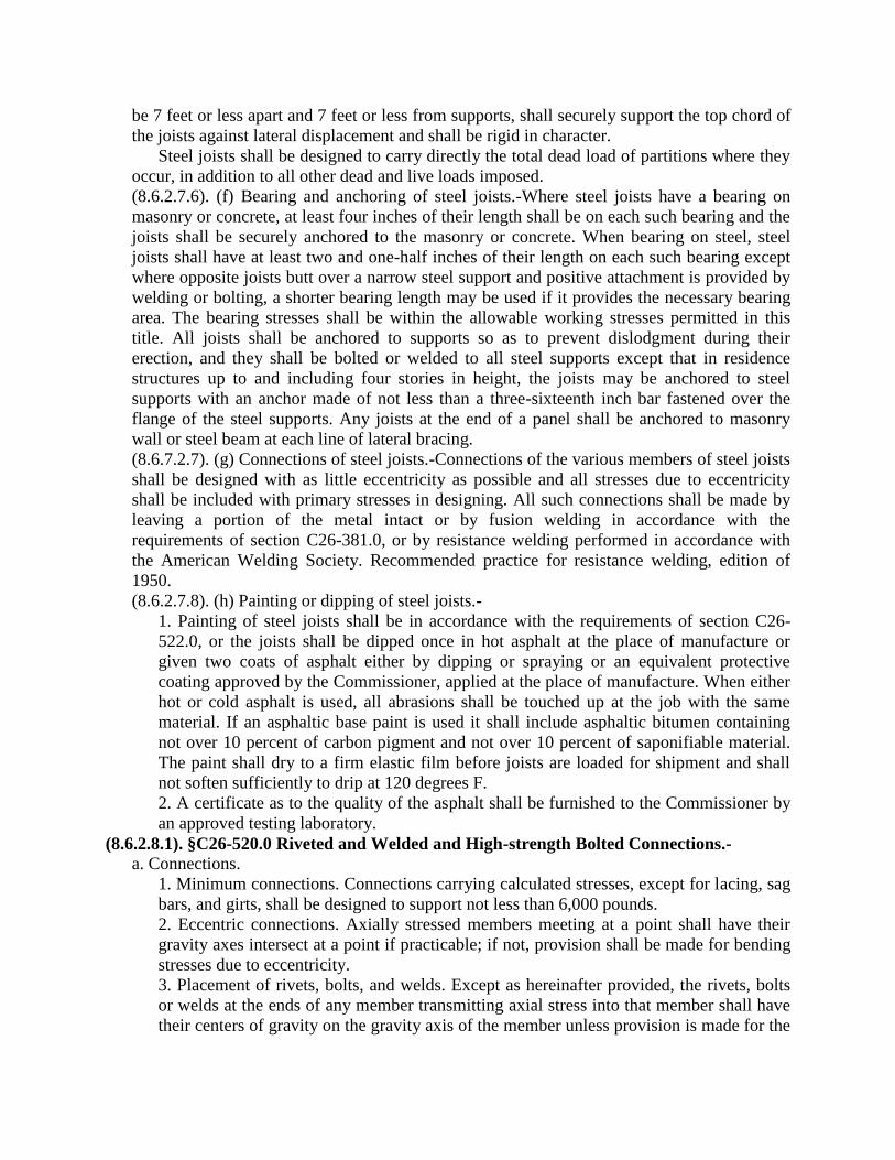
be 7 feet or less apart and 7 feet or less from supports, shall securely support the top chord of
the joists against lateral displacement and shall be rigid in character.
Steel joists shall be designed to carry directly the total dead load of partitions where they
occur, in addition to all other dead and live loads imposed.
(8.6.2.7.6). (f) Bearing and anchoring of steel joists.-Where steel joists have a bearing on
masonry or concrete, at least four inches of their length shall be on each such bearing and the
joists shall be securely anchored to the masonry or concrete. When bearing on steel, steel
joists shall have at least two and one-half inches of their length on each such bearing except
where opposite joists butt over a narrow steel support and positive attachment is provided by
welding or bolting, a shorter bearing length may be used if it provides the necessary bearing
area. The bearing stresses shall be within the allowable working stresses permitted in this
title. All joists shall be anchored to supports so as to prevent dislodgment during their
erection, and they shall be bolted or welded to all steel supports except that in residence
structures up to and including four stories in height, the joists may be anchored to steel
supports with an anchor made of not less than a three-sixteenth inch bar fastened over the
flange of the steel supports. Any joists at the end of a panel shall be anchored to masonry
wall or steel beam at each line of lateral bracing.
(8.6.7.2.7). (g) Connections of steel joists.-Connections of the various members of steel joists
shall be designed with as little eccentricity as possible and all stresses due to eccentricity
shall be included with primary stresses in designing. All such connections shall be made by
leaving a portion of the metal intact or by fusion welding in accordance with the
requirements of section C26-381.0, or by resistance welding performed in accordance with
the American Welding Society. Recommended practice for resistance welding, edition of
1950.
(8.6.2.7.8). (h) Painting or dipping of steel joists.-
1. Painting of steel joists shall be in accordance with the requirements of section C26-
522.0, or the joists shall be dipped once in hot asphalt at the place of manufacture or
given two coats of asphalt either by dipping or spraying or an equivalent protective
coating approved by the Commissioner, applied at the place of manufacture. When either
hot or cold asphalt is used, all abrasions shall be touched up at the job with the same
material. If an asphaltic base paint is used it shall include asphaltic bitumen containing
not over 10 percent of carbon pigment and not over 10 percent of saponifiable material.
The paint shall dry to a firm elastic film before joists are loaded for shipment and shall
not soften sufficiently to drip at 120 degrees F.
2. A certificate as to the quality of the asphalt shall be furnished to the Commissioner by
an approved testing laboratory.
(8.6.2.8.1). §C26-520.0 Riveted and Welded and High-strength Bolted Connections.-
a. Connections.
1. Minimum connections. Connections carrying calculated stresses, except for lacing, sag
bars, and girts, shall be designed to support not less than 6,000 pounds.
2. Eccentric connections. Axially stressed members meeting at a point shall have their
gravity axes intersect at a point if practicable; if not, provision shall be made for bending
stresses due to eccentricity.
3. Placement of rivets, bolts, and welds. Except as hereinafter provided, the rivets, bolts
or welds at the ends of any member transmitting axial stress into that member shall have
their centers of gravity on the gravity axis of the member unless provision is made for the

effect of the resulting eccentricity. Except in members subject to repeated variations in
stress, as defined in section C26-368.0 d, disposition of filled welds to balance the forces
about the neutral axis or axes for end connections of single angle, double angle, and
similar type members is not required, eccentricity between the gravity axes of such
members and the gage lines for their riveted or bolted end connections may be neglected.
4. Unrestrained members. Except as otherwise indicated by the designer, connections of
beams, girders or trusses shall be designed as flexible, and may ordinarily be
proportioned for the reaction shears only.
Flexible beam connections shall permit the ends of the beam to rotate sufficiently to
accommodate its deflection by providing for a horizontal displacement of the top flange
determined as follows:
e = 0.007d, when the beam is designed for full uniform load and for live load
deflection not exceeding 1/360 of the span.
e = fbL
3,600,000 when the beam is designed for full uniform load producing
3,600,000 the unit stress fb at mid-span.
5. Restrained members. Fasteners or welds for end connections of beams, girders and
trusses not conforming to the requirements of subsection 4 above, shall be designed for
the combined effect of end reaction shear and tensile or compressive stresses resulting
from moment induced by the rigidity of the connection when the member is fully loaded.
6. Fillers. When rivets or bolts carrying computed stress pass through fillers thicker than
¼ inch, except in friction-type connections assembled with high strength bolts, the fillers
shall be extended beyond the splice material and the filler extension shall be secured by
enough rivets or bolts to distribute the total stress in the member uniformly over the
combined section of the member and the filler, or an equivalent number of fasteners shall
be included in the connection.
In welded construction, any filler ¼ inch or more in thickness shall extend beyond the
edges of the splice plate and shall be welded to the part on which it is fitted with
sufficient weld to transmit the splice plate stress, applied at the surface of the filler as an
eccentric load. The welds joining the splice plate to the filler shall be sufficient to
transmit the splice plate stress and shall be long enough to avoid overstressing the filler
along the toe of the weld. Any filler less than ¼ inch thick shall have its edges made flush
with the edges of the splice plate and the weld size shall be the sum of the size necessary
to carry the splice plate stress plus the thickness of the filler plate.
7. Connection of tension and compression members in trusses. The connections at ends of
tension or compression members in trusses shall develop the strength required by the
stress, but not less than 50 percent of the effective strength of the member. Groove welds
in connections at the ends of tension or compression members in trusses shall be
complete penetration groove welds.
8. Compression members with bearing joints. Where compression members bear on
bearing plates, and where tier-building columns are finished to bear, there shall be
sufficient rivets, bolts or welds to hold all parts securely in place
Where other compression members are finished to bear, the splice material and its
riveting, bolting or welding shall be arranged to hold all parts in line and shall be
proportioned for 50 percent of the computed stress.
All of the foregoing joints shall be proportioned to resist any tension that would be
developed by the specified lateral forces acting in conjunction with 75 percent of the
calculated dead load stress and no live load.
9. Combination of welds. If two or more of the general types of weld (butt, fillet, plug,
slot) are combined in a single joint, the effective capacity of each shall be separately
computed with reference to the axis of the group, in order to determine the allowable
capacity of the combination.
10. Rivets and bolts in combination with welds. In new work, rivets, A307 bolts, or high
strength bolts used in bearing type connections, shall not be considered as sharing the
stress in combination with welds. Welds, if used, shall be provided to carry the entire
stress in the connection. High strength bolts installed in accordance with the provisions of
section C26-520.0 d, as a friction-type connection prior to welding may be considered as
sharing the stress with the welds.
Existing rivets and properly tightened high strength bolts may be utilized for the
purpose of carrying stresses resulting from existing dead loads when existing structures
are altered by welding, and welds shall be of sufficient strength to carry all additional
stress.
11. High strength bolts (in friction-type joints) in combination with rivets. In new work
and in making alterations, rivets and high strength bolts, installed in accordance with the
provisions of section C26-520.0 d, as friction-type connections, may be considered as
sharing the stresses resulting from dead and live loads.
12. Field connections. Rivets, high strength bolts or welds shall be used for the following
connections:
Column splicers in tier structures 200 feet or more in height.
Column splices in tier structures 100 to 200 feet in height, if the least horizontal
dimension is less than 40 percent of the height.
Column splices in tier structures less than 100 feet in height, if the least horizontal
dimension is less than 25 percent of the height.
Connections of all beams and girders to columns and of any other beams and girders
on which the bracing of columns is dependent, in structures over 125 feet in height.
Roof-truss splices and connections of trusses to columns, column splices, column
bracing, knee braces and crane supports, in all structures carrying cranes of over 5-ton
capacity.
Connections for supports of running machinery, or of other live loads which produce
impact or reversal of stress.
Any other connections stipulated on the design plans.
In all other cases field connections may be made with A 307 bolts.
For the purpose of this section, the height of a tier structure shall be taken as the
vertical distance from the curb level to the highest point of the roof beams, in the case of
flat roofs, or to the mean height of the gable, in the case roofs having a rise of more than
2-2/3 in 12. Where the curb level has not been established, or where the structure does
not adjoin a street, the mean level of the adjoining land shall be used instead of curb
level. Penthouses may be excluded in computing the height of structure.
b. Rivets and bolts.
1. High strength bolts. Use of high strength bolts shall conform to the provisions of
subsection d. of this section, except that A354, Grade BC, bolts approved by the board

and tightened to their proof load, may be substituted for A325 bolts at the working
stresses permitted in section C26-368.0 c.
2. Effective bearing area. The effective bearing area of rivets and bolts shall be the
diameter multiplied by the length in bearing, except that for countersunk rivets and bolts
half the depth of the countersink shall be deducted.
3. Long grips. Rivets and A307 bolts which carry calculated stress, and the grip of which
exceeds five diameters, shall have their number increased 1 percent for each additional
1/16 inch in the grip.
4. Minimum pitch. The minimum distance between center, of rivet and bolt holes shall be
not less than 2-2/3 times the nominal diameter of the river or bolt but preferably not less
than 3 diameters.
5. Minimum Edge Distance. The minimum distance from the center of a rivet or bolt hole
to any edge, used in design or in preparation of shop drawings, shall be that given in the
following table:
Rivet or Bolt
Minimum Edge Distance for Punched, Reamed or Drilled
Holes (Inches)
Diameter (Inches) At Sheared Edges
At Rolled Edges of Plates,
Shapes or Bars or Gas Cut
Edges**
1/2 7/8 3/4
5/8 1 1/8 7/8
¾ 1 1/4 1
7/8 1 1/2* 1 1/8
1 1 3/4* 1 1/4
1 1/8 2 1 1/2
1 1/4 2 1/4 1 5/8
Over 1 1/4 1 3/4 × Diameter 1 1/4 × Diameter
*These may be 1 1/4 in. at the ends of beam connection angles.
**All edge distances in this column may be reduced 1/8 in. when the hole is at a point per
stress does not exceed 25 percent of the maximum allowed stress in the element.
6. Minimum edge distance in line of stress. In bearing-type connections of tension
members, where there are not more than two fasteners in a line parallel to the direction of
stress, the distance from the center of the end fastener and that end of the connected part
toward which the stress is directed shall not be less than
(a) for riveted connections: the area of the fastener divided by the thickness of the
connected part for fasteners in single shear, and twice this distance for fasteners in
double shear.
(b) for high strength bolted connections: 1 1/2 times the distances given in (a) above.
The end distance may, however, be decreased in such proportion as the fastener stress
is less than that permitted under section C26-368.0 c. 8, (1), but it shall not be less than
the distance specified in section C26-520.0 b. 5. above.
When more than two fasteners are provided in the line of stress the provisions of
section C26-520.0 b. 5. shall govern.
7. Maximum edge distance. The maximum distance from the center of any rivet or bolt to
the nearest edge of parts in contact with one another shall be 12 times the thickness of the
plate, but shall not exceed 6 inches.

c. Welds
1. Welder and welding operator qualifications. Welds shall be made only by welders and
welding operators who have been previously qualified by tests as prescribed in section
C26-351.0, to perform the type of work required, except that this provision need not
apply to tack welds not later incorporated into finished welds carrying calculated stress.
2. Qualification of weld and joint details. The details of all joints (including for butt
welds the groove form, root face, root spacing, etc.) to be employed under this title
without welding procedure qualifications shall comply with all the requirements for joints
which are accepted without procedure qualification under the standard code for arc and
gas welding in building construction, 1946 edition, or the standard specifications for
welded highway and railway bridges, 1956 edition, of the American Welding Society.
Weld grooves for complete penetration welds which are accepted without welding
procedure qualification under the standard code for arc and gas welding in building
construction or the standard specification for welded highway and railway bridges of the
American Welding Society may be used under this specification without welding
procedure qualification. Weld grooves of the 60° single-V or 45° single bevel form and
single-J or single-U grooves, conforming to the details of such grooves as provided in the
above American Welding Society standards but having partial penetration with an
effective throat thickness as defined in section C26-515.0 g, 6, and no root opening, may
be used without welding procedure qualification. However, they shall not be used in butt
joints to resist tensile stress acting in a direction normal to the plane of the weld throat,
except in splices or connections of columns or other members subject primarily to axial
compressive stress.
Joint forms or welding procedures other than those included in the foregoing may be
employed provided they shall have been qualified in accordance with the requirements of
the above American Welding Society standards.
E60 and E70 series electrodes for manual arc-welding and grade SAW-l or grade
SAW-2 submerged arc process may be used for welding A7 and AJ6 steel. Only E70 low
hydrogen electrodes for manual arc-welding or Grade SAW-2 for submerged arc-welding
shall be used with A441 or weldable A242 steel except that fillet welds or partial
penetration groove welds used to connect parts of built-up members and not carrying
calculated stress may be made with E60 series low hydrogen electrodes and Grade SAW-
l submerged arc process.
3. Minimum size of fillet welds. In joints connected only by fillet welds, the minimum
size of fillet weld to be used shall be as shown in Table A below. Weld size is determined
by the thicker of the two parts joined, except that the weld size need not exceed the
thickness of the thinner part joined unless a larger size is required by calculated stress: Table A
Material Thickness of Thicker Part Joined
(Inches) Minimum Size of Fillet Weld (Inches)
To 1/2 inclusive 3/16
Over 1/2 to 3/4 1/4
Over 3/4 to 1 1/2 5/16
Over 1 1/2 to 2 1/4 3/8
Over 2 1/4 to 6 1/2
Over 6 5/8
4. Maximum effective size of fillet welds. The maximum size of a fillet weld that may be
assumed in the design of a connection shall be such that the stresses in the adjacent base
material do not exceed the values allowed in section C26-368.0 c. The maximum size that
may be used along edges of connected parts shall be:
(1.) Along edges of material less than 1/4 inch thick, the maximum size may be equal
to the thickness of the material.
(2.) Along edges of material 1/4 inch or more in thickness, the maximum size shall be
1/16 inch less than the thickness of the material, unless the weld is especially
designated on the drawings to be built out to obtain full throat thickness.
5. Length of fillet welds. The minimum effective length of a strength fillet weld shall be
not less than 4 times the nominal size, or else the size of the weld shall be considered not
to exceed one-fourth of its effective length.
6. Intermittent fillet welds. Intermittent fillet welds may be used to transfer calculated
stress across a joint or faying surfaces when the strength required is less than that
developed by a continuous fillet weld of the smallest permitted size, and to join
components of built-up members. The effective length of any segment of intermittent
fillet welding shall be not less than 4 times the weld size with a minimum of 10 inches.
7. Lap joints. The minimum width of laps on lap joints shall be 5 times the thickness of
the thinner part joined and not less than 1 inch. Lap joints joining plates or bars subjected
to axial stress shall be fillet welded along the edge of both lapped parts except where the
deflection of the lapped parts is sufficiently restrained to prevent opening of the joint
under maximum loading.
8. End returns of fillet welds. Side or end fillet welds terminating at ends or sides,
respectively, of parts or members shall, wherever practicable, be returned continuously
around the corners for a distance not less than twice the nominal size of the weld. This
provision shall apply to side and top fillet welds connecting brackets, beam seats, and
similar connections on the plane about which bending moments are computed. End
returns shall be indicated in the design and detail drawings.
9. Fillet welds in holes and slots. Fillet welds in holes or slots may be used to transmit
shear in lap joints or to prevent the buckling or separation of lapped parts, and to join
components of built-up members. Such fillet welds may overlap, subject to the provisions
of section C26-515.0 g, 6. Fillet welds in holes or slots are not to be considered plug or
slot welds.
10. Plug and slot welds. Plug or slot welds may be used to transmit shear in a lap joint or
to prevent buckling of lapped parts and to join component parts of built-up members.
The diameter of the holes for a plug weld shall be not less than the thickness of the
part containing it plus 5/16 inch, rounded to the next greater odd 1/16 inch, nor greater
than 2 1/4 times the thickness of the weld metal.
The minimum center-to-center spacing of plug welds shall be 4 times the diameter of
the hole.
The length of slot for a slot weld shall not exceed 10 times the thickness of the weld.
The width of the slot shall be not less than the thickness of the part containing it, plus
5/16 inch, rounded to the next greater odd 1/16 inch, nor shall it be greater than 2 1/4
times the thickness of the weld. The ends of the slot shall be semicircular or shall have
the corners rounded to a radius not less than the thickness of the part containing it, except
those ends which extend to the edge of the part.
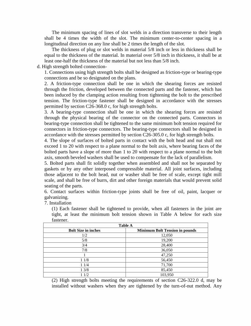
The minimum spacing of lines of slot welds in a direction transverse to their length
shall be 4 times the width of the slot. The minimum center-to-center spacing in a
longitudinal direction on any line shall be 2 times the length of the slot.
The thickness of plug or slot welds in material 5/8 inch or less in thickness shall be
equal to the thickness of the material. In material over 5/8 inch in thickness, it shall be at
least one-half the thickness of the material but not less than 5/8 inch.
d. High strength bolted connection-
1. Connections using high strength bolts shall be designed as friction-type or bearing-type
connections and be so designated on the plans.
2. A friction-type connection shall be one in which the shearing forces are resisted
through the friction, developed between the connected parts and the fastener, which has
been induced by the clamping action resulting from tightening the bolt to the prescribed
tension. The friction-type fastener shall be designed in accordance with the stresses
permitted by section C26-368.0 c, for high strength bolts.
3. A bearing-type connection shall be one in which the shearing forces are resisted
through the physical bearing of the connector on the connected parts. Connectors in
bearing-type connection shall be tightened to the same minimum bolt tension required for
connectors in friction-type connectors. The bearing-type connectors shall be designed in
accordance with the stresses permitted by section C26-305.0 c, for high strength bolts.
4. The slope of surfaces of bolted parts in contact with the bolt head and nut shall not
exceed 1 to 20 with respect to a plane normal to the bolt axis, where bearing faces of the
bolted parts have a slope of more than 1 to 20 with respect to a plane normal to the bolt
axis, smooth beveled washers shall be used to compensate for the lack of parallelism.
5. Bolted parts shall fit solidly together when assembled and shall not be separated by
gaskets or by any other interposed compressible material. All joint surfaces, including
those adjacent to the bolt head, nut or washer shall be free of scale, except tight mill
scale, and shall be free of burrs, dirt and other foreign materials that would prevent solid
seating of the parts.
6. Contact surfaces within friction-type joints shall be free of oil, paint, lacquer or
galvanizing.
7. Installation
(1) Each fastener shall be tightened to provide, when all fasteners in the joint are
tight, at least the minimum bolt tension shown in Table A below for each size
fastener. Table A
Bolt Size in inches Minimum Bolt Tension in pounds
1/2 12,050
5/8 19,200
3/4 28,400
7/8 36,050
1 47,250
1 1/8 56,450
1 1/4 71,700
1 3/8 85,450
1 1/2 103,950
(2) High strength bolts meeting the requirements of section C26-322.0 d, may be
installed without washers when they are tightened by the turn-of-nut method. Any
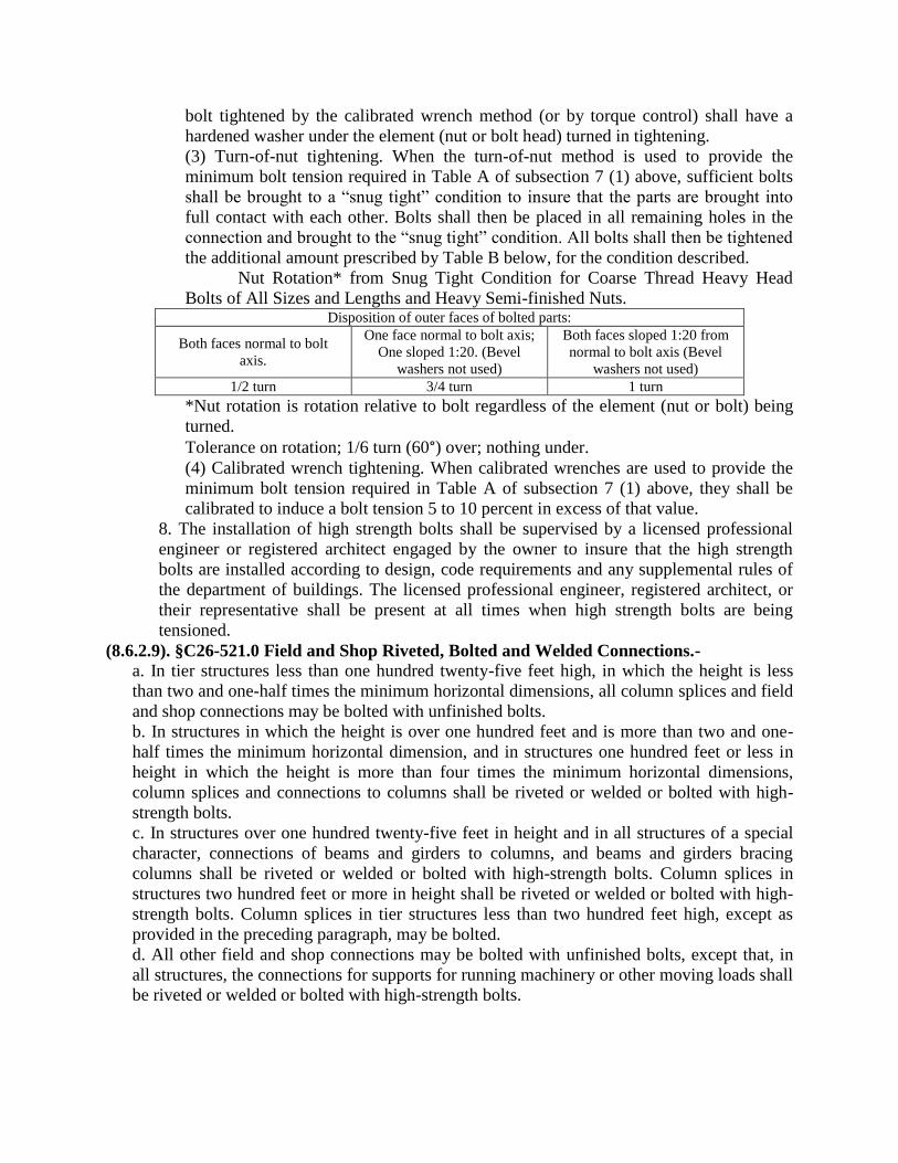
bolt tightened by the calibrated wrench method (or by torque control) shall have a
hardened washer under the element (nut or bolt head) turned in tightening.
(3) Turn-of-nut tightening. When the turn-of-nut method is used to provide the
minimum bolt tension required in Table A of subsection 7 (1) above, sufficient bolts
shall be brought to a “snug tight” condition to insure that the parts are brought into
full contact with each other. Bolts shall then be placed in all remaining holes in the
connection and brought to the “snug tight” condition. All bolts shall then be tightened
the additional amount prescribed by Table B below, for the condition described.
Nut Rotation* from Snug Tight Condition for Coarse Thread Heavy Head
Bolts of All Sizes and Lengths and Heavy Semi-finished Nuts. Disposition of outer faces of bolted parts:
Both faces normal to bolt
axis.
One face normal to bolt axis;
One sloped 1:20. (Bevel
washers not used)
Both faces sloped 1:20 from
normal to bolt axis (Bevel
washers not used)
1/2 turn 3/4 turn 1 turn
*Nut rotation is rotation relative to bolt regardless of the element (nut or bolt) being
turned.
Tolerance on rotation; 1/6 turn (60°) over; nothing under.
(4) Calibrated wrench tightening. When calibrated wrenches are used to provide the
minimum bolt tension required in Table A of subsection 7 (1) above, they shall be
calibrated to induce a bolt tension 5 to 10 percent in excess of that value.
8. The installation of high strength bolts shall be supervised by a licensed professional
engineer or registered architect engaged by the owner to insure that the high strength
bolts are installed according to design, code requirements and any supplemental rules of
the department of buildings. The licensed professional engineer, registered architect, or
their representative shall be present at all times when high strength bolts are being
tensioned.
(8.6.2.9). §C26-521.0 Field and Shop Riveted, Bolted and Welded Connections.-
a. In tier structures less than one hundred twenty-five feet high, in which the height is less
than two and one-half times the minimum horizontal dimensions, all column splices and field
and shop connections may be bolted with unfinished bolts.
b. In structures in which the height is over one hundred feet and is more than two and one-
half times the minimum horizontal dimension, and in structures one hundred feet or less in
height in which the height is more than four times the minimum horizontal dimensions,
column splices and connections to columns shall be riveted or welded or bolted with high-
strength bolts.
c. In structures over one hundred twenty-five feet in height and in all structures of a special
character, connections of beams and girders to columns, and beams and girders bracing
columns shall be riveted or welded or bolted with high-strength bolts. Column splices in
structures two hundred feet or more in height shall be riveted or welded or bolted with high-
strength bolts. Column splices in tier structures less than two hundred feet high, except as
provided in the preceding paragraph, may be bolted.
d. All other field and shop connections may be bolted with unfinished bolts, except that, in
all structures, the connections for supports for running machinery or other moving loads shall
be riveted or welded or bolted with high-strength bolts.

e. Within existing structures steel work for alterations, or additions, except to the main
structural framework, which do not affect existing column splices, connections and other
riveted or welded work, may be bolted with unfinished bolts.
f. Roof-truss splices and connections of trusses to columns, column splices, column bracing,
knee braces and crane supports, in all structures carrying cranes shall be riveted, welded or
bolted with high strength bolts.
(8.6.2.10). §C26-522.0. Painting of Structural Steel.-
a. All structural steel, except as provided in subsection b of this section shall receive one coat
of approved metal protection before erection, applied thoroughly and evenly to dry surfaces
which have been cleaned by hand wire brushing, or by other suitable methods of loose mill
scale, loose rust, weld slag flux deposit, dirt and other foreign matter. Oil and grease deposits
shall be removed by solvents. Surfaces inaccessible after assembly shall be treated as
required above prior to assembly.
b. Surfaces of structural steel shall not be required to receive approved metal protection when
used under the following conditions, however these surfaces shall be cleaned of oil or grease
by solvent cleaners and be cleaned of dirt and other foreign material by thorough brushing
with a fiber brush.
1. Structural steel which is to be encased in non-corrosive concrete or surfaces that will
abut non-corrosive concrete at interior locations.
2. Structural steel which is to be encased in approved non-corrosive fire resistive
materials and to which an adhesive is included in the application.
3. Surfaces of structural steel which are to be riveted, bolted or welded in close contact
with each other.
4. Surfaces of structural steel within two inches of field welds shall be free of protective
coverings that would prevent proper welding or produce objectionable fumes while
welding is being done.
5. Surfaces of structural steel which have been machine finished.
6. Surfaces of structural steels meeting the specifications for atmospheric corrosion
resistant steel shown by test to not require metal protection and having been approved by
the board.
c. Part of structural steel members left unpainted because of welding, bolting or riveting
operations not exempted from painting by the provisions of sub-section b above, shall receive
a field application of approved metal protection as prescribed in sub-section a above.
d. Structural steel, except approved atmospheric corrosion resistant grades, which will remain
exposed to atmospheric corrosion shall receive an additional coat of acceptable metal
protection of another color after erection.
e. Should the metal protection required on structural steel surfaces become excessively
deteriorated due to prolonged exposure or any other cause the commissioner may require
additional metal protection in whole or in part.
(8.6.2.11). §C26-523.0 Templates.-When any lintel, beam, girder or truss is supported at either
end by a wall or pier, such lintel, beam, girder or truss shall be properly anchored to such wall or
pier and shall rest upon a template or shoe of cast iron, steel or stone of such design and
dimensions as to safely distribute its load on the masonry, except that when beams, not
exceeding six inches in depth, are placed not more than thirty inches on centers, templates shall
be unnecessary.

(8.6.2.12). §C26-524.0 Protection of Structural Steel from Weather.-Exterior steel columns in
walls, which columns are unprotected by glass, or similar material, shall be protected from the
weather by efficient and approved waterproof material or by at least eight inches of masonry.
GROUP 3
Gas Cutting of Structural Steel
(8.6.3.1). §C26-525.0 Oxygen Cutting of Structural Steel Permitted.-Oxygen cutting may be
employed in the fabrication of structural steel members or parts, used in building construction, in
accordance with rules of the board.
(8.6.3.2.1). §C26-526.0 Use of Oxygen Cutting Torch.-
a. Competence to use oxygen cutting torch. Contractors desiring to do oxygen cutting shall
satisfy the superintendent as to their ability to produce satisfactory oxygen cuts.
(8.6.3.2.2). b. Oxygen cutting of structural steel while carrying stress. It shall be unlawful to
do oxygen cutting on any member while it is carrying stress, except for detail cutting to
correct minor fabricating errors where the removal of metal resulting from such detail cutting
would leave unimpaired the required strength of the members to be cut.
(8.6.3.2.3). c. Oxygen cut edges. Oxygen cut edges shall be smooth and regular in contour.
(8.6.3.2.4). d. Oxygen cutting in preparation for welding. Oxygen cutting may be used in the
preparation of base metal parts for welding provided the edges are thoroughly cleaned after
cutting so as to expose clean steel.
(8.6.3.2.5). e. Milling of surfaces by oxygen cutting. It shall be unlawful to do oxygen cutting
to replace the milling of surfaces.
(8.6.3.2.6). f. Oxygen cutting of undesigned holes. It shall be unlawful to do oxygen cutting
of holes in a member designed without provision therefor.
(8.6.3.2.7). g. Radius and area of re-entrant oxygen cut fillets. The radii of re-entrant oxygen
cut fillets shall be as large as possible and at least one-half inch. To determine the net area of
members so cut, one-eighth of an inch shall be deducted from the oxygen cut edges.
GROUP 4
Structural Steel for Stair Construction
(8.6.4). §C26-527.0 Structural Steel for Stair Construction.-
a. Steel stringers for interior stairs shall have a minimum thickness of three-sixteenths of an
inch, except the webs of hot rolled beams or channels which shall have a minimum thickness
of .145 of an inch.
b. Material for risers, treads, and landing plates for interior stairs shall have a minimum
thickness equal to No. 12 U.S. standard gage iron.
c. Material used for the construction of exterior steel stairs or fire escapes shall be at least
one-quarter of an inch in thickness.
Sub-Article 7. Wood Construction
GROUP 1
General Requirements for Wood Construction
(8.7.1.1). §C26-528.0 Support of Wood Structural Members.-
a. The ends of wood beams, joists and rafters resting on masonry walls shall be cut to a bevel
of three inches in their depth, and shall have a bearing of at least four inches on the masonry.

b. The ends of wood beams resting on girders shall have bearings of at least four inches.
c. The ends of wood beams framing into girders may be supported by approved metal
stirrups, hangars or bolted hardwood cleats, provided that all bearings of timber shall be at
least four inches or as may be otherwise designed and shown in detail on the framing plans
and have a bearing within the working stress of the timbers.
d. It shall be unlawful, except in the case of one and two family dwellings, to support either
end of a floor or roof beam on stud partitions. Tail beams over eight feet long and trimmer
and header beams shall be hung in approved metal stirrups or hangers and shall be spiked
unless supported on a wall or girder.
e. It shall be unlawful to notch or cut wood beams, joists or rafters unless they are suitably
reinforced.
f. Built-up girders shall be securely bolted together. Other built-up members shall be securely
spiked or bolted together. Spiked trusses shall be of types which have been tested and
approved.
(8.7.1.2). §C26-529.0 Bridging of Wood Beams.-Wood floor beams and beams in flat roofs
exceeding eight feet in clear span shall be braced with mitered cross bridging measuring at least
one inch by two and one-half inches (actual), nailed twice as each bearing, or, if metal bridging
is used, it must have equivalent effective strength and durability. The maximum distance
between bridging or between bridging and bearing shall be eight feet.
(8.7.1.3.1). §C26-530.0 Anchoring and Fastening of Wood Beams and Girders.-
a. Anchoring of Wood Beams and Girders to Masonry.-Each tier of beams parallel to
masonry and beams and girders bearing on masonry shall provide adequate lateral stability
by anchorage as required in section C26-416.0.
(8.7.1.3.2). b. Fastening of Wood Beams on Girders.-The ends of wood beams resting upon
girders, walls or bearing partitions required to be anchored in accordance with section C26-
416.0, except as otherwise provided, shall lap each other at least six inches and be well
bolted or spiked together or shall be butted end to end and fastened by approved metal straps,
ties, or dogs in the same beams as the wall anchors. The ends of such wood beams framing
into girders shall be tied together with approved metal straps or dogs so as to provide
continuity in the same beams as the wall anchors.
(8.7.1.3.3). c. Fastening of Wood Girders.-The ends of wood girders shall be fastened to each
other by approved straps, ties or dogs.
(8.7.1.4.1). §C26-531.0 Fire Prevention.-
a. Trimming Around Flues and Fireplaces.-Wood beams shall be trimmed away from flues
and chimneys. The header and trimmer beams shall be at least four inches from the face of
chimneys and backs of fireplaces. In front of a fireplace an opening shall be trimmed to
support a trimmer arch or approved masonry hearth at least-sixteen inches from the face of
the breast and at least twelve inches wider than the fireplace opening on each side.
(8.7.1.4.2). b. Separation of Combustible Members in Masonry Walls.-Combustible members
entering a masonry wall shall be separated from each other and from the outside of the wall
by at least four inches of solid masonry.
(8.7.1.5). §C26-532.0 Wood Columns and Posts.-
a. Wood columns and posts shall have level bearings and shall be supported on properly
designed metal bases or base plates.

b. Where timber columns are superimposed they shall be squared at the ends perpendicular to
their axis and supported on metal caps with brackets or shall be connected by properly
designed metal caps, pin ties and base plates.
(8.7.1.6). §C26-533.0 Bolting in Wood Construction.-Bolts in wood construction shall be
provided with washers and when carrying tensile stress they shall be of such proportions that the
compression on the wood at the face of the washer will be less than the working stresses
prescribed in section C26-370.0.
(8.7.1.7). §C26-534.0 Stud Bearing Partitions.-
a. Stud bearing partitions which rest directly over each other and are not parallel with wood
floor beams shall run down between the wood floor beams and rest on the top plate of the
partition girder or foundation below.
b. Stud bearing partitions parallel to the floor joists shall be supported on doubled joists, or
beams, at least as wide as the studs supported.
(8.7.1.8.1). §C26-535.0 Fire-Stops.-
a. Fire-Stopping of Stud Bearing Partitions.-Exterior stud walls and stud bearing partitions
shall have the studding filled in solid between the uprights to the depth of all floor beams
with suitable incombustible materials.
(8.7.1.8.2). b. Fire-Stopping of Furred Spaces.-Where walls are furred off, or studded off, the
space between the inside of the furring or studding and the wall shall be fire-stopped from the
ceiling to the under side of the flooring or roof above with incombustible material.
GROUP 2
Frame Structures of Wood
(8.7.2.1) §C26-536.0 Height of Wood Frame Structures.-The maximum height of any frame
structure erected after January first, nineteen hundred thirty-eight, or enlarged after January first,
nineteen hundred thirty-eight, shall be as provided in article five of this title. It shall be unlawful
to use more than two stories for living quarters in two family residence buildings.
(8.7.2.2). §C26-537.0 Area of Wood Frame Structures.-
a. The maximum area of any wood frame structure erected after January first, nineteen
hundred thirty-eight, or enlarged after January first, nineteen hundred thirty-eight, shall be as
provided in article five of this title.
b. Attached wood frame dwellings in rows and semi-detached dwellings housing more than
two families shall be separated by unpierced fire partitions.
(8.7.2.3). §C26-538.0 Wood Frame Construction Details.- a. The framework of wood frame structures shall conform to the balloon frame, braced
frame, or platform frame types and shall consist of sills, posts, girts, or ribbon strips and
plates mutually braced at all angles or by wood sheathing laid diagonally and nailed twice at
each bearing. The corner posts shall be at least the equivalent of three two by four inch
timbers, and sills shall be at least four by six inches or three by eight inches. Mortise and
tenon framing shall be used only with timbers at least four by six inches (nominal). All
structural parts of the wood framework shall be built at least twelve inches above the
adjoining finished grade.
b. Approved fibre board sheathing at least one-half of an inch in thickness and four feet in
width may be used instead of wood sheathing when bearing on four studs and fastened to
each bearing with nails spaced six inches or less apart, except that where necessary for fitting

around openings and similar purposes, the dimension of each board used for such purpose
shall be the maximum possible if such board is less than four feet in width.
c. Gypsum sheathing board, at least one-half of an inch in thickness and two feet in width
may be used instead of wood sheathing when set horizontally and fastened to each bearing
with one and three-quarter inch (No. 10 1/2 gage) galvanized flat head roofing nails spaced
four inches or less apart.
(8.7.2.4). §C26-539.0 Wood Shingle Roofing.-
a. It shall be unlawful to use wood shingles on the roof of any structure erected after January
first, nineteen hundred thirty-eight, or to replace with wood shingles any roofing of other
than wood shingles.
b. It shall be unlawful to replace wood shingle roofing on structures erected before January
first, nineteen hundred thirty-eight, with wood shingle roofing, except when:
1. Shingles are placed on a solid roof deck, with rust resistive nails;
2. Shingles are of vertical or edge grain having a thickness of two inches in five shingles,
measured at the butt (American lumber standard);
3. The maximum exposure of such wood shingle roofing to the weather is:
(a) for roofs with a pitch of more than thirty degrees from the horizontal:
Five inches for sixteen-inch shingles
Five and one-half inches for eighteen-inch shingles
Seven and one-half inches for twenty-four-inch shingles
(b) for roofs with a pitch between twenty-two and one-half degrees and thirty degrees
from the horizontal:
Four inches for sixteen-inch shingles
Four and one-half inches for eighteen-inch shingles
Six and one-half inches for twenty-four-inch shingles
(8.7.2.5). §C26-540.0 Covering of Wood Frame Towers.-All towers on wood frame structures
shall be roofed with approved incombustible roofing, except as provided in section C26-539.0.
(8.7.2.6.1). §C26-541.0 Minor Wood Frame Structures.-
a. Wood Frame Sheds.-Wood frame sheds, open on at least one side, may be erected of wood
or with approved fibre board siding, throughout the city, but such sheds shall be fifteen feet
or less in height, shall cover twenty-five hundred square feet or less, shall be placed at least
four feet from any lot line, and shall be covered on the sides and roof with approved fire
retarding material.
(8.7.2.6.2). b. Wood Frame Outhouses.-Wooden outhouses used exclusively for domestic
purposes may be constructed throughout the city to a wall height of eight feet, and may be
one hundred fifty square feet in area, provided the roofs are covered with approved fire
retarding materials and the walls are located at least three feet from the lot line.
(8.7.2.6.3). c. Wood Frame Builders' Shanties.-One-story structures for the use of builders in
connection with any building operation for which a permit has been issued, may be
constructed of wood, or may be sheathed with approved fibre board, and placed on the lot
where such building operation is carried on in any part of the city, or on adjoining lots if such
structures do not interfere with the safe occupancy of any structures thereon, or on the sheds
provided over the sidewalks in front of such building operation.
(8.7.2.6.4). d. Wooden Fences.-Wooden fences may be erected throughout the city to a
maximum height of ten feet, except as provided in section C26-257.2 of the code.
(8.7.2.7.2). §C26-542.0 Temporary Wood Frame Structures and Tents.-
a. Permit Requirements for Temporary Wood Frame Structures and Tents.-It shall be
unlawful to erect temporary wood frame structures and tents until a permit, specifying the
purpose and the period of maintenance, shall have been obtained from the superintendent.
(8.7.2.7.3). b. Location of Temporary Wood Frame Structures and Tents.-It shall be unlawful
to place temporary structures, which are enclosed in any manner, nearer than four feet to any
lot line.
(8.7.2.7.4). c. Removal of Temporary Wood Frame Structures and Tents.-Every temporary
structure shall be removed at the expiration of the period or periods for which the permit was
issued.
(8.7.2.7.5). d. Unlawful Use of Temporary Wood Frame Structures and Tents.-It shall be
unlawful to use any temporary structure for any other purpose than that designated in the
permit.
(8.7.2.7.6). e. Area of Tents.-No tent shall exceed twenty-five hundred square feet in area.
(8.7.2.8). §C26-543.0 Miscellaneous Wood Frame Structures.-Miscellaneous wood frame
structures of an unusual character to which the provisions of this article are not directly
applicable, including structures for fair and exhibition purposes, towers for observation,
amusement devices, greenhouses and lumber sheds, and temporary structures of any kind, shall
be erected in accordance with plans approved by the superintendent.
§C26-543.1 Steel and Wood Frame Structures.-
a. Dining cars or lunch wagons-dining cars or lunch wagons not exceeding fifteen feet in
height and 1,200 square feet in area may be constructed of steel frames with wood nailers
fastened thereto to permit interior and exterior finishing with wood sheathing. The sheathing
on walls and roof to be provided with an incombustible veneer or metal asbestos cement
composition sheets or vitreous tile. The flooring shall be of vitreous tile or equal, placed on a
one-inch tongue and groove underflooring except behind counters which shall be of tongue
and groove hardwood.
All spaces between roof rafters and side-walls to be filled with a two-inch fire-proof
insulation. The trim around doors and windows may be of wood construction. The minimum
thickness of metal in the steel frame-work shall be one-eighth of an inch, provided that the
safe loads and unsupported lengths specified elsewhere in this title are not exceeded.
b. Jurisdiction and supervision over said dining cars or lunch wagons shall be under the
Department of Housing and Buildings.
c. Permits may be revoked for just causes upon thirty (30) days' notice to the owners.
d. The structure must at all times be kept in a sanitary, safe and attractive condition.
Sub-Article 8. Glass Veneer
(8.8). §C26-544.0 General.-Glass veneer on the exterior of structures may be used only in
accordance with the provisions of this title and the rules of the board.
(8.8.1). §C26-545.0 Minimum Thickness.-The minimum thickness of glass veneer shall be
eleven-thirty-seconds of an inch, except that where glass veneer extends within four inches or
less of the sidewalk level, the minimum thickness of that portion of the veneer below a level of
four inches above the sidewalk at its point of intersection with the veneer shall be seven-
sixteenths of an inch.

(8.8.2). §C26-546.0 Maximum Area and Dimensions.-
a. The maximum area of a single section of glass veneer shall not exceed ten square feet in
area when fifteen feet or less above the level of the sidewalk directly below and shall not
exceed six square feet in area when more than fifteen feet above the level of the sidewalk
directly below.
b. The maximum length of any section of glass veneer shall be sixty inches.
(8.8.3). §C26-547.0 Edges.-All edges of each plate of glass veneer shall be ground square. It
shall be unlawful to use mitred joints.
(8.8.4). §C26-548.0. Backing for Glass Veneer.-Glass veneer may be placed only against
substantial, rigid, incombustible surfaces of true plane, plumb and straight. The backing shall in
any case provide rigidity and stability equal to or greater than that provided by one-inch thick
cement mortar on wire lath secured to studs spaced twelve inches or less on centers. It shall be
unlawful to use wood backing surfaces, regardless of whether they are fire-proofed.
(8.8.5). §C26-549.0 Setting of Glass Veneer.-
a. Glass veneer shall be set only when the backing is thoroughly dry and after the application
of a thorough and uniform bond coat of material approved by the board. The bond coat shall
be such as to effectively seal the portions of the veneer backing and to insure against the
absorption of the vital properties of the mastic cement.
b. Mastic cement approved by the board shall be applied to the back surface of each plate of
the glass veneer, which veneer shall be applied to the backing with a substantial and uniform
pressure over its entire area sufficient to flatten out the gobs of mastic cement to a thickness
of between one-quarter of an inch and five-eighths of an inch. Sufficient mastic cement shall
be applied to insure that at least sixty percent of the total area of the section is bonded to the
backing.
c. The bond coat and the mastic cement shall be of one manufacture and shall be certified to
be of such composition as to insure close affinity between the two materials.
d. Abutting edges of glass veneer shall be ground square and uniformly buttered with an
approved pointing compound.
e. Where glass veneer extends to the sidewalk surface each such section shall rest on two
cushions of approved resilient material, one near the end of each such section or plate.
Cushions shall be one-quarter of an inch or more in thickness. The joint between the bottom
edge of the glass section and the top of the sidewalk shall be caulked with a waterproof
compound.
f. Where the glass veneer is permitted to extend below the level of the sidewalk surface, an
expansion joint of one-quarter of an inch of more shall be provided between the outer face of
the glass veneer and the edge of the sidewalk. Such expansion joint space shall be filled with
a resilient caulking compound from the level of the sidewalk surface to a depth at least three-
quarters of an inch below such level.
g. Where glass veneer is applied at an elevation more than eight feet above the sidewalk
surface, the mastic cement binding shall be supplemented by the use of metal clip angles of a
design approved by the board. Clips shall be located in each vertical or horizontal edge of
each section of veneer and shall be secured through the backing directly into the wall behind
by means of expansion bolts and in a manner satisfactory to the superintendent. Angle clips
shall be two inches or more in length and shall be of at least No. 16 U.S. gage, and shall be
so designed as to furnish at least two-inch bearing support on each clip and shall hold the
glass in a vertical plane independently of the mastic cement.

h. All horizontal joints shall be cushioned with pads of adhesive asphaltic tape which shall
extend from the rear surface of the glass to one-eighth of an inch or less from the front
surface. Horizontal joints shall be buttered with joint cement over the full depth of the joint,
including the surface of the cushion tape.
i. Shelf angles of approved design shall be set at vertical intervals of three feet or less, in all
horizontal joints located eight feet or less above the sidewalk except that, where there are
show windows, it shall be unnecessary to have shelf angles below the level of the tops of the
show window bulkheads. Shelf angles shall be of a type approved by the board and shall be
secured to the backing in a manner satisfactory to the superintendent.
j. Where glass veneer is confined between non-resilient materials at ends expansion shall be
provided for by means of an expansion joint at each end of one-quarter of an inch or more
throughout the entire height of the veneer.
(8.8.6). §C26-550.0 Flashing.-Upon the completion of glass veneer installation, exposed edges
shall be flashed with non-corrodible sheet metal and caulked with a waterproof compound.
Flashing and waterproof compounds and their application shall be as prescribed by the
superintendent.
§C26-550.1. Glass Blocks.-
a. Glass blocks may be used in the construction of exterior walls and interior walls and in
partitions of structures in accordance with the provisions of this title and the rules of the
board.
b. The term “glass blocks” as used in this title shall mean glass units partially evacuated,
consisting of two halves made of pressed glass effectively sealed in manufacture. These units
shall have a minimum thickness of 3 3/4 inches and a maximum dimension of 11 3/4 inches.
The blocks may have various face patterns and special shapes may be used for such purposes
as corners, trims and curves not to exceed the dimensions noted herein.
The mortar face of glass blocks shall be treated so as to insure an effective bond with the
mortar.
c. Permitted uses of glass blocks: Glass block construction may be used in exterior wall
openings, which openings could otherwise be filled with windows, either isolated or in
continuous bands. Glass block construction shall not be deemed an integral part of a wall or
partition nor shall it bear any load other than its own weight. No isolated panel nor portion of
continuous hand of glass block construction shall exceed 20 feet in height nor 25 feet in
length without adequate intermediate supports and expansion joints. No such panel nor
portion of continuous band shall exceed 144 square feet in area.
Glass block construction may be used for non-bearing interior partitions which are not
required to have a prescribed fire resistive rating, provided that the maximum area of any
individual panel does not exceed 250 square feet except that where fire resistive ratings have
been satisfactorily established in accordance with provisions of the administrative code such
legally established ratings will be recognized by the department.
d. Fire department access panels: Above the first story or ground floor in every story of a
building, fire department access panels shall be provided in every frontage, spaced not more
than 50 feet apart on centers horizontally. Each such panel shall consist either of a fixed sash
with a single sheet of glass at least 32 inches wide and 48 inches high set in metal frame, or a
movable metal sash at least 32 inches wide and 48 inches high and openable either from
exterior or interior. Wherever practicable one such panel in each story shall give access to a

stairway or, where there is no stairway at the front exterior wall, one such panel in each story
shall provide access as close as practicable to a stairway.
e. Glass blocks shall be laid up in mortar of the following proportions by volume: one part
portland cement, one part hydrated lime or lime putty, four to six parts of clean well graded
sand.
Mortar shall be mixed as nearly dry as is consistent with good workmanship. Neither
anti-freeze agents nor accelerators shall be used in mortar.
f. Walt ties: Wall ties are to be installed in horizontal mortar joints as follows:
In the first four stories in height, but in no case more than the first 52 feet in height:
Block sizes-Maximum 6 inches by 6 inches in every fourth course.
Block sizes-Maximum 8 inches by 5 inches in every fourth course.
Block sizes-More than 6 inches by 6 inches or 8 inches by 5 inches and not more than 8
inches by 8 inches in every third course.
Block sizes-More than 8 inches by 8 inches and not more than 12 inches by 12 inches in
every course.
In buildings not over nine stories in height, in the fourth and succeeding stories and in all
cases above a height of 52 feet, ties shall be provided in every second course except in the
cases of blocks exceeding a face size of 8 inches by 8 inches, where ties shall be provided in
every course. Where glass blocks are used above the ninth story in any exterior wall opening
panel exceeding 60 square feet in area, wall ties shall be used in every course regardless of
the size of the blocks used.
Ties shall be either flat expanded metal mesh, 20 gauge in thickness, galvanized after
forming 2 3/8 inches wide, or galvanized steel wire mesh of two parallel longitudinal wires
number 16 gauge or larger, spaced 2 inches apart and having welded thereto number 16 or
heavier gauge cross wires at intervals not exceeding 8 inches. All ties shall run continuously
with ends lapping at least 6 inches.
g. All glass block panels shall be held in place in the wall openings at both jambs, so as to
resist the reaction resulting from a wind pressure of 20 pounds per square foot of panel.
Resistance shall provide for both internal and external pressure.
h. All glass block panels shall be provided with expansion joints at the sides and top.
Expansion joints shall be entirely free of mortar, and shall be filled with resilient material
such as premoulded strips of fibrous glass covered with asphalted paper, or resilient cork,
loose oakum, mineral wool or other material approved by the board.
Both sides of each expansion joint shall be lined with tightly packed oakum or similar
material and pointed with non-hardening caulking material. The depth of caulking shall be
not less than 1/2 inch.
i. The sills of glass block panels, previous to the laying of the first mortar course, shall be
coated with approved asphalt emulsion.
j. Veneer or ashlar: Glass blocks may be used as exterior wall veneer under rules of the
board.
k. Fire resistive ratings: Nothing herein contained shall be construed as limiting the use of
glass block construction as fire resistive construction where a prescribed fire resistive rating
is required, provided such construction after prescribed tests is approved by the board as an
opening protective assembly or partition of specified fire resistive rating.

(8.8.7). §C26-550.2. Glass Facing.-
a. Where glass is used for facing the exterior walls of a structure, and the glass is supported
independently on metal framing carried on the structural supports, the glass facing shall
conform to the following requirements:
1. Glass shall be firmly held in a metal frame continuously on all edges.
2. Frame and structural supports shall be adequate to resist a pressure of 30 pounds per
square foot applied on either side of the glass surface, without exceeding the stress
limitations provided in Article 8 of this title for the materials specified.
If other materials are used, the stresses shall not exceed the limitations used in
accepted engineering practice.
3. The space between the glass facing and the spandrel construction shall be fire stopped
at each story with concrete, metal or other incombustible material secured in place.
4. Glass conforming in area and thickness to the limitations set forth in the following
table 1, shall be assumed adequate to withstand a wind pressure of 30 pounds per square
foot from either direction: Table 1
Nominal glass
thickness SS 1/8" 3/16" 1/4" 5/16" 11/32"
3/8" or
thicker
Maximum area
allowed in square feet 5.8 12 27 48 75 90 108
Note-SS means single strength.