1931MNRAS..91..569L The Precise Measurement of...
9
1931MNRAS..91..569L Mar. 1931. The Precise Measurement of Time. The Precise Measurement of Time. By Alfred L. Loomis. (Plates 9 and 10.) In August 1928 an investigation was started at this laboratory on the precise measurement of time. Among others, it had the following bjects in view :- ( I ) A study of the most accurate types of pendulum clocks now in existence. . (2) A study of other time-keeping devices. (3) The development of methods for the automatic and continuous intercomparison of a group of time-keepers. . (4) The development, if possible, of improved time-keepers after a comprehensive study of the limitations of existing instruments. This preliminary paper deals only with certain aspects of the first three of these objects. In my opinion, the Shortt clock * is, at the present time, the most accurate, time-keeper for all periods longer than a day. This 'opinion is based upon the published paper� of Professor R. A. Sampson dealing with Shortt Clocks No. ° and NO. 4 at the Royal Observatory at Edin- burgh, t the papers of Dr. J. Jackson and Mr. W. Bowyer dealing with the Shortt Clock� NO. 3 and No. I I at the Royal Observatory at Greenwich,t my own studies and those of Professor E. W. Brown and Dr. Brouwer § o£ Shortt Clocks Nos. 20, 21, 22 at Tuxedo, and the publications of the B.I.H. dealing with the performance of a large number of Riefler and Leroy clocks at the Paris Observatory. I have also personally inspected the clock installations at a considerable number of places. For periods of one day or less, I believe the most precise method of 'measuring intervals of time is with the crystal oscillators developed at ·the Bell Telephone Laboratories in New York under the direction of . M r. W. A. Marrison. 1 I Since 1929 May these crystal oscillators have been continuously compared with the Shortt clocks at Tuxedo by means .of a private wire between New York and Tuxedo and the chronograph to be described in the next section. I know of no published results that indicate tha� there is any other type of orystal oscillator or tuning- fork controlled oscillator that can compare with. the Bell Telephone Laboratories oscillators. These osc i nators can be read more precise l y than the Shortt clocks -over periods of a day or less solely because of their greater "velocity. " IThey oscillate 100,000 times a second, and two of them can be compared ·with each other (as described by Mr. Marrison in his paper) with such precision that a change of I part in 101 0 can be detected over a period . 6£ 10 seconds. In this period they have completed 106 oscillations. * Designed by . Shortt and manufactured by The Synchronome Com p any , London. t Proc. Roy. ' Soc. of Edinburgh, 48, pt. ., No. 13, 1928. t M.N., 88, 469, 1928; M.N., 89, 242, 1929; M.N., 90, 268, 1930. § M.N., 91, 575, 1931. II W. A. Marrison, Bell Telephone Laboratories Journal, 8, 493, 1929. © Royal Astronomical Society • Provided by the NASA Astrophysics Data System
Transcript of 1931MNRAS..91..569L The Precise Measurement of...

1931MNRAS..91..569L
Mar. 1931. The Precise Measurement of Time.
The Precise Measurement of Time. By Alfred L. Loomis. (Plates 9 and 10. )
In August 1928 an investigation was started at this laboratory on the precise measurement of time. Among others, it had the following () bj ects in view :-
( I ) A study of the most accurate types of pendulum clocks now in existence.
.
(2) A study of other time-keeping devices. (3) The development of methods for the automatic and continuous
intercomparison of a group of time-keepers. .
(4) The development, if possible, of improved time-keepers after a comprehensive study of the limitations of existing instruments.
This preliminary paper deals only with certain aspects of the first three of these objects.
In my opinion, the Shortt clock * is, at the present time, the most accurate, time-keeper for all periods longer than a day. This 'opinion is based upon the published paper� of Professor R. A. Sampson dealing with Shortt Clocks No. ° and NO. 4 at the Royal Observatory at Edinburgh, t the papers of Dr. J . Jackson and Mr. W. Bowyer dealing with the Shortt Clock� NO. 3 and No. I I at the Royal Observatory at Greenwich,t my own studies and those of Professor E. W. Brown and Dr. Brouwer § o£ Shortt Clocks Nos. 20, 21, 22 at Tuxedo, and the publications of the B.I.H. dealing with the performance of a large number of Riefler and Leroy clocks at the Paris Observatory. I have also personally inspected the clock installations at a considerable number of places.
For periods of one day or less, I believe the most precise method of 'measuring intervals of time is with the crystal oscillators developed at ·the Bell Telephone Laboratories in New York under the direction of .Mr. W. A. Marrison. 1I Since 1929 May these crystal oscillators have been continuously compared with the Shortt clocks at Tuxedo by means .of a private wire between New York and Tuxedo and the chronograph to be described in the next section. I know of no published results that indicate tha� there is any other type of orystal oscillator or tuningfork controlled oscillator that can compare with. the Bell Telephone Laboratories oscillators.
These oscina tors can be read more precisely than the Shortt clocks -over periods of a day or less solely because of their greater " velocity." IThey oscillate 100,000 times a second, and two of them can be compared ·with each other (as described by Mr. Marrison in his paper) with such precision that a change of I part in 1010 can be detected over a period .. 6£ 10 seconds. In this period they have completed 106 oscillations.
* Designed by Mr. Shortt and manufactured by The Synchronome Company, London.
t Proc. Roy. 'Soc. of Edinburgh, 48, pt. ii., No. 13, 1928.
t M.N., 88, 469, 1928; M.N., 89, 242, 1929; M.N., 90, 268, 1930. § M.N., 91, 575, 1931. II W. A. Marrison, Bell Telephone Laboratories Journal, 8, 493, 1929.
© Royal Astronomical Society • Provided by the NASA Astrophysics Data System
1931MNRAS..91..569L
570 Mr. Alfred L. Loomis, XCI. 5,.
In the same period the pendulum of a Shortt clock has moved, only 350 mm. The paper by Professor Brown and Dr Brouwer shows the limits of accuracy to which the clocks can be read over periods of one hour. This question is also discussed in the next section.
The Loomis Ohronograph.
No comprehensive study of a group of time-keepers can be made, without a continuously recording chronograph. Chronograph No. I was designed and builp in this laboratory in 1928 August and was in constant operation until 1930 March when it was superseded by Chronograph NO.2, identical in principle but containing several refinements. This chronograph (see figs. I and 2) gives a continuous record permitting the direct intercomparison between the clocks and the crystals and between the clocks themselves. It gives the same resolution as would be obtained by a tape moving past a pen at the rate of 10 feet per second and on which was recorded a signal from each clock every 30' seconds. This result is obtained as follows: The motor of the chronograph has a toothed iron disc mounted on a vertical shaft which is caused to rotate ten times a second and whose exact speed is controlled by the masteT crystal oscillator in New York. This oscillator has a frequency of 100,000 cycles per second, and by the use of a submultiple generator controls the frequency of a looo-cycle oscillator. This looo-cycle frequency is led over the private wire from the Bell Telephone Laboratories in New York to Tuxedo and is fed, through an amplifier, to three small magnets round the iron disc of the chronograph. This. disc has 100 teeth, a�d when spinning in approximate synchronism with. the 100o-cycle impulses makes 10 revolutions per second (advancing one tooth per cycle). As a result, it is "locked" to the master oscillator illNew York and must follow all variations in frequency of the master.
At the top of the vertical shaft carrying the rotor is a short hori-· zontal arm of bakelite revolving inside a bakelite ring. This ring carries 100 steel phonograph needles, equally spaced around a horizontal circle, and pointing inward towards the revolving arm. Above this.. circle of needles is a circle of brass, and on the end of the insulated. revolving arm there is mounted a short piece of tungsten, its upper end approaching to within a millimetre of the brass circle and its lower end. sweeping past the needle-points.
An insulated wire leads from each of the 100 needles in the ring to 100 needles mounted in a horizontal strip of bakelite, called the" comb."" The needles in the comb are in a straight line and spaced T10 of an inch apart, the comb being 10 inches in length.
The rest of the chronograph consists of a large roll of coarse paper, slightly more than 10 inches in width, which is fed slowly through brass rollers which print 100 parallel lines spaced Ttr of an �inch apart. The p�per then passes under the needles in the" comb," each of the 100 needle-points being directly over one of the 100 lines. Directly' under the paper is a brass plate which is kept at ground potentiaL When a high potential is suddenly applied to the brass circle in the·,
© Royal Astronomical Society • Provided by the NASA Astrophysics Data System

1931MNRAS..91..569L
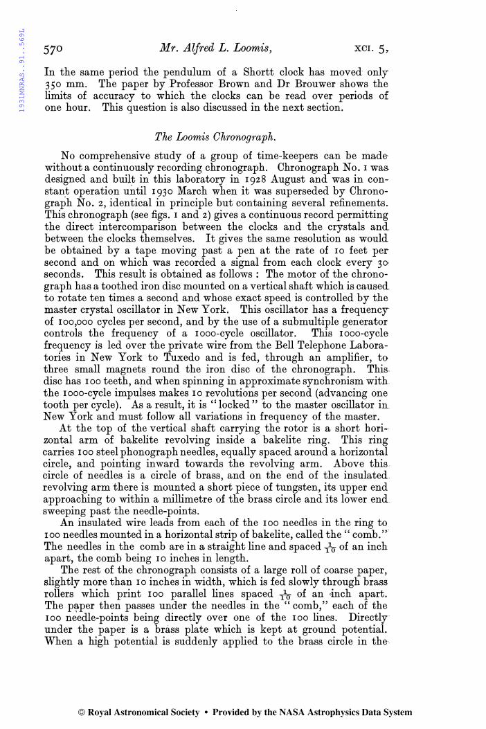
MONTHLY NOTICES OF R.A.S. VOL XCI. PLATE 9.
© Royal Astronomical Society • Provided by the NASA Astrophysics Data System

1931MNRAS..91..569L
Mar. 1931. The Precise Measurement of Time. 57I
bakelite ring a spark jumps from this circle to the upper end of the piece of tungsten on the rotating arm, then from its lower end to the nearest needle in the bakelite ring. From here the impulse travels down the wire to the corresponding needle in the " comb," and from this needle a spark jumps through the paper to the brass plate below.
The paper is caused to pass at a uniform rate under the needle-,points by brass rollers connected through reduction gears directly with the revolving shaft of the chronograph. The paper is fed at the rate of approximately a foot an hour. At this rate it takes about six weeks for a roll of the paper to be fed through the chronograph.
The operation of the instrument is as follows :-The rotating " spark point" on the bakelite arm sweeps past 1000
needle-points per second. The points in the comb are Ttr of an inch apart, and this distance on the paper therefore corresponds to I milli-second ( ·OO IS) . Each master clock sends out a signal every 30 seconds. This signal operates a special relay which causes a spark to pass as described above (the details of the spark circuit are described later). If a clock and the crystal oscillator are keeping exactly the same time, each successive spark will jump from the same needle-point and, as the paper is continuously moving, a straight line of spark-marks will be formed parallel to the edge of the paper. The scale of this chronograph is so enormous that a change of one part in a million is immediately apparent by the mere inspection of a few hours' record� Thus if two clocks are maintaining the same rate and are, for example, 10 milli-seconds different in phase, they will trace two parallel lines of sparks I inch (10 milli-seconds) apart. If one clock changed its rate by one part in a million, it would then gain (or lose as the case might be) on the other clock 10 milli -seconds in ten million milli-seconds, or a pproximately 3 hours. As the paper would have travelled 3 feet in this time, the two lines would have then come together or separated to a distance of 2 inches-a change easily visible by inspection.
The shi�t of a line in respect to the paper gives the relative rates ()f the clock making such line and the master crystal.' The relative shift of two lines with respect to each other gives the relative rates of two clocks irrespective of the rate of the master crystal.
Fig. 2 is a photograph of the record as it comes from the chronograph. Lines I, 2, and 3 were made by the three clocks. They are parallel to within a few milli-seconds per day. Line 4, which has a pronounced slope, was made by another crystal oscillator . It was losing on the clocks at the rate of 120 of a second per day.
, The chronograph records for a 24o-day period beginning 1929 September 7 have been most carefully analysed by Professor E. W. Brown and Dr. Brouwer. Their results are contained in their paper which appears on p. 575. They show that the mean hourly rates, each determined from 120 sparks (one every 30 seconds) will have a probable error of less than ·0001 second.
This remarkable result is accomplished through the possibility of averaging a large number of observations. A single impulse from a master Shortt clock has an uncertainty of I or 2 milli -seconds. The
© Royal Astronomical Society • Provided by the NASA Astrophysics Data System

1931MNRAS..91..569L
572 Mr. Alfred L. Loomis, XCI. 5,
master pendulum carries a small wheel. The impulse arm rests on this wheel, and as the pendulum swings out the pallet on this arm travels down the edge of the wheel, finally falling clear. It then trips an arm which falls, making the electric contact. If the small wheel is not exactly circular the arm will fall at slightly different times as the wheel is given a small turn with each fall. These variations are entirely smoothed out when a series of sparks are averaged.
In the three clocks at Tuxedo the small wheels have slightly different irregularities, and as a result the line of sparks from each of the clocks has its own characteristic irregularities. These irregularities have persisted over the entire two years of observation and are of great convenience in permitting the ready identification of different lines of sparks. Calculation shows that a variation of I milli-second in the record would be made by a difference of radii of ·005 millimetre in two parts of on� of these small wheels.
We know that this variation between successive sparks of I or z milli-seconds is not caused by variations in any other part of the recording system because such variations are entirely absent when we use another crystal oscillator instead of a Shortt clock to send 30-second impulses to the chronograph.
An essential part of the chronograph concerns the method of producing "the sparks." As is well known, the use of ordinary sparks for recording phenomena is almost obsolete. Unless specially prepared paper is used, the spark holes are almost impossible to detect. But with the method here used each spark causes a small "explosion � in the coarse wrapping-paper, which leaves a "crater" easily visible across the room when viewed under oblique illumination. This result is obtained by using a special circuit. A 30 m.f. condenser is slowly charged up to 240 volts, through a high resistance. The voltage is supplied from six "B" batteries. The current drain is so small that a set of such batteries lasts for about a year. When a relay is closed the impedance in the circuit is so small that a momentary current of the order of 50 amperes is rapidly built up in the primary of a small induction coil. This is sufficient to charge a Leyden jar to 20,000 volts, at which voltage a control gap breaks down, and the spark jumps at the needle-point. Some care was required in adjusting the voltage, resistance, capacity, and size of the control gap, but when once adjusted it has operated without attention since 1928 August. This type of circuit produces a high voltage surge of short duration and small energy. This produces the explosive effect in the paper without burning it in the slightest.
As previously stated, the chronograph prints 100 parallel lines on the paper and the sparks fall on these lines. The printing rollers are so arranged that a short gap occurs in each loth line at 20-minute intervals. Thus the exact time of the occurrence of each spark can be readily obtained. The 100 lines are thus also broken up into groups of 10. The 1st, 5th, and 9th lines in each group of 10 are suppressed. It is thus possible, by mere inspection, and without the use of any scale, to give the exact milli-second in which any spark occurred. The reading of the record is therefore not so laborious as would at first
© Royal Astronomical Society • Provided by the NASA Astrophysics Data System

1931MNRAS..91..569L
MONTHLY NOTICES OF R.A.S. VOL. XCI. PLATE 10.
Fig. 2.
© Royal Astronomical Society • Provided by the NASA Astrophysics Data System

1931MNRAS..91..569L
Mar. 1931. The Precise Measurement of Time. 573
seem, and the record is always visible, right up to the point at which the sparks are occurring, and there is no delay such as would be caus�d by having to develop or otherwise treat the paper. An hourly average can be quickly obt,ained by merely counting the number of sparks in each column. From these numbers the mean can be quickly found by calculation. For example, if the 120 sparks are distributed as follows: 40 in colu,mn 10, 60 in column I I, and 20 in column 12,-the mean for the hour is 10·83 milli-seconds [(400 + 660 + 240) -:- 120].
-
The Installation at Tuxedo.-The three clocks at Tuxedo are mounted' on independent massive masonry piers. The piers are arranged in a triangle so that the planes of the three pendulums form an equilateral triangle. The piers are built directly on the solid rock'which makes up the mountain on which the laboratory is situated. The neighbourhood is remarkably free from vibration, as the nearest railway is more than two miles distant and there is no heavy road traffic within a mile. The vault in which the piers are located is kept at a constant temperature of 21°'00 ± ·02 centigrade.
Clock No. 20 was installed in 1928 July, and clocks No. 21 and No. 22 in .1928 December, and all have been functioning remarkably well ever SInce.
Oomments on the Shortt Olocks.-Mter two years of observation of the Shortt clocks the following considerations occur to me:-
(a) The pressure in the clock case should be adjusted to be within _- the range 15 to 25 mID. of mercury. As the pressure in the clock case is reduced from 760 mm. to 25 mm. the rate of the clock increases about 9 seconds per day. In the range 15 to 25 mm. the change of rate is very small, but when the pressure is further reduced from 15 mm. to less than I mm. the rate decreases over a second per day. This was first observed, at Tuxedo when the clocks were installed in 1928. Air was admitted I mm. at a time and the rate observed on the chronograph. The fact that the maximum rate is found with a pressure of about 15 mm. has also been observed by Dr. Jackson.* This maximum results from the fact that the curve " Rate v. Pressure" is' the resultant of two curves, one being " Pressure v. Effective Mass of Bob." As the pres .. sure is reduced, less air is carried along with the pendulum and less air is displaced by the pendulum. The resultant of these two effects is to cause the effective centre of gravity to rise and the rate to increase. We have studied this effect with a �'constant amplitude" clock (referred to later). The other curve is " Pressure v. Amplitude." As the pressure is reduced the amplitude increases, because a larger amplitude is needed to dissipate the constant increments of energy fed in every 30 seconds. This effect is most marked at the lower pressures. Owing to the " circular error," this causes a reduction in rate as the pressure is decreased. We have also studied this effect with the "constant amplitude" clock by keeping the pressure constant and changing the amplitude.
* M.N., 90, 276, 1930.
© Royal Astronomical Society • Provided by the NASA Astrophysics Data System

1931MNRAS..91..569L
574 The Precise Measurement of Time. XCI. 5,
The best way to adjust the pressure in a Shortt clock is to pump it down as far as possible, then admit nitrogen from a tank, and then pump the nitrogen down to the desired pressure. When air is used, the sparks occurring at the contact of the resetting device gradually " clean up " the oxygen, thus reducing the pressure. Several observers have reported the reduction of pressure with time in a sealed clock case.
It seems extraordinary to physicists who are used to the usual "vacuum tecpnique " that such large waxed joints as are found in all precision clocks can hold tight for years; yet the experience at Greenwich, Tuxedo, and elsewhere indicates that these waxed joints in the Shortt clocks do in fact hold. Nevertheless, when a clock changes its rate there is always a suspicion that there may be a small leak. For example, a variation of over t second in a year would be caused at a pressure of 24 mm. if the pressure changed io of a mm. Therefore, at Tuxedo we are experimenting, in cpnnection with another kind of clock, to see if we cal1not have an " all glass" case sealed off in the flame.
The clocks contain a mercury and an oil gauge. N-Butyl-phthalate �hould be used in the oil gauge. This compound has the lowest vapour pressure of any suitable organic compound and is extremely stable at room temperature. The mercury in the other gauge should also be covered with a small quantity of this compound to prevent the mercury from distilling on to the pendulum.
(b) The variation of arc of the pendulum is by far the most serious �actor to be contended with. This applies to all conventional types of clocks, and in the Shortt " free p�ndulum" type it is probably less serious than in the usual type which has an " escapement" drive. This factor comes into play because of the" circular error." A variation of over ! second a year would be caused by a variation of arc of ib-o of a millimetre. ·
From �his point of view and because of the " circular error" a �onventional tyPe clock is an ungoverned motor. Energy is fed in at as constant a rate as possible, and the velocity of the pendulum in:creases until it dissipates energy at the same rate. A new position of �quilibrium is required for each ch�nge in energy input. It is essential, therefore, that on existing clocks the " amplitude" be, regularly read and recorded. Dr. Jaokson (M.N., 90, 272, 1930) shows how-most of the large variations in Greenwich clock NO. 3 can be explained and corrected by applying corrections for variation of arc.
We have attacked this problem, at Tuxedo from a different angle. A clock is now operating there whose arc is -kept constant �t a figure slightly less than that which it would take if unregulated. Whenever the . arc exceeds this predetermined amount by more' than a micron the energy input is momentarily cut off. In principle it is essentially a motor with a governor. It is too early to report as to whether or not this principle is superior to the principle of an' automatic device to record changes in arc.
(c) The Shortt clocks have invar pendulums and" type-metal" bobs. Invar is known to be a ra�her unstable .alloy. It was selected because
© Royal Astronomical Society • Provided by the NASA Astrophysics Data System

1931MNRAS..91..569L
Mar. I93I. Analysis of Records made on Loomis Chronograph. 575
of its small temperature coefficient. Many Shortt clocks have shown a progressive slowing down, as if the pendulums were slowly lengthening or as if the bobs were settling. On one of the clocks at Greenwich an invar bob was substituted in 1929.
Fused quartz has been suggested by a number of people for the pendulum rod. I know of no installation where this material has been used and tested for a sufficient length of time to show whether or not it is superior to invar. We are making experiments at this lahoratory along this line.
(d) If a master Shortt clock is accidentally stopped by failure of the "slave" clock, broken wire, or battery failure, etc., it can easily be started again without breaking the vacuum seals. All that is necessary is to open for a second the valve which is located in the side of the case opposite the bob. The rush of air causes the bob to move slightly. If the valve is then opened slightly and closed at regular 2-second intervals in phase with the pendulum, the full amplitude can be built up in a minute or two. Then the pressure can be pumped down to the original amount.
(e) The brass case of the Shortt clock contains four bolt-holes for fastening the clock to the wall. Only the upper two holes should be used. The lower part of the clock should merely press against a layer of plaster of Paris placed on the wall. When four bolts are used any shifting in the masonry necessarily puts a strain on the case, causing a slow leak. In each of the clocks at Tuxedo a slow leak developed in �bout six months after installation, and in each case it was instantly cured when the lower nuts were loosened. I also understand that several other installations have had the same trouble.
While the installation at Tuxedo was made chiefly for experimental - purposes, the recording, with some interruptions, has been continuous, and is being continued under somewhat better conditions. It has, however, been remembered that it is possible to carry out experiments which are denied to an observatory, where the clocks are needed for the time service and for astronomical observations, and it is hoped that these opportunities can be further utilised.
Tuxedo Park, N. Y. : 193I Feb'0ary 16.
Analysis of Records made on the Loomis Chronograph by Three Shortt Cloe-ks and a Crystal Oscillator. By Ernest W. Brown and Dirk Brouwer.
The chronograph, clocks, and oscillator have been described by _ Mr. A. L. Loomis in the previous paper. In this paper we give the
results of a somewhat extensive analysis of records furnished by Mr. Loomis, extending over several months.
Frequency of Reading.-Let us denote the time shown by the quartz crystal system by Q and those by the th�ee Shortt clocks
© Royal Astronomical Society • Provided by the NASA Astrophysics Data System