(19) TZZ¥ T - Chalmers Research
25
Note: Within nine months of the publication of the mention of the grant of the European patent in the European Patent Bulletin, any person may give notice to the European Patent Office of opposition to that patent, in accordance with the Implementing Regulations. Notice of opposition shall not be deemed to have been filed until the opposition fee has been paid. (Art. 99(1) European Patent Convention). Printed by Jouve, 75001 PARIS (FR) (19) EP 3 115 149 B1 TEPZZ¥__5_49B_T (11) EP 3 115 149 B1 (12) EUROPEAN PATENT SPECIFICATION (45) Date of publication and mention of the grant of the patent: 14.03.2018 Bulletin 2018/11 (21) Application number: 15175782.0 (22) Date of filing: 08.07.2015 (51) Int Cl.: B24B 5/42 (2006.01) B24B 51/00 (2006.01) (54) METHOD OF GRINDING A WORKPIECE HAVING A CYLINDRICAL BEARING SURFACE AND METHOD FOR DETERMINING PROCESSING PARAMETERS VERFAHREN ZUM SCHLEIFEN EINES WERKSTÜCKS MIT EINER ZYLINDERLAGERFLÄCHE SOWIE VERFAHREN ZUR BESTIMMUNG VON VERARBEITUNGSPARAMETERN PROCÉDÉ DE MEULAGE D’UNE PIÈCE AYANT UNE SURFACE DE PALIER CYLINDRIQUE ET PROCÉDÉ DE DÉTERMINATION DE PARAMÈTRES DE TRAITEMENT (84) Designated Contracting States: AL AT BE BG CH CY CZ DE DK EE ES FI FR GB GR HR HU IE IS IT LI LT LU LV MC MK MT NL NO PL PT RO RS SE SI SK SM TR (43) Date of publication of application: 11.01.2017 Bulletin 2017/02 (73) Proprietor: Scania CV AB 151 87 Södertälje (SE) (72) Inventors: • KRAJNIK, Peter 41713 Göteborg (SE) • ROININEN, Roope 151 44 Södertälje (SE) • DRAZUMERIC, Radovan 1215 Medvode (SI) (74) Representative: Scania CV AB Patents, GP 117kv 151 87 Södertälje (SE) (56) References cited: US-B1- 6 878 043
Transcript of (19) TZZ¥ T - Chalmers Research

Note: Within nine months of the publication of the mention of the grant of the European patent in the European PatentBulletin, any person may give notice to the European Patent Office of opposition to that patent, in accordance with theImplementing Regulations. Notice of opposition shall not be deemed to have been filed until the opposition fee has beenpaid. (Art. 99(1) European Patent Convention).
Printed by Jouve, 75001 PARIS (FR)
(19)E
P3
115
149
B1
TEPZZ¥__5_49B_T(11) EP 3 115 149 B1
(12) EUROPEAN PATENT SPECIFICATION
(45) Date of publication and mention of the grant of the patent: 14.03.2018 Bulletin 2018/11
(21) Application number: 15175782.0
(22) Date of filing: 08.07.2015
(51) Int Cl.:B24B 5/42 (2006.01) B24B 51/00 (2006.01)
(54) METHOD OF GRINDING A WORKPIECE HAVING A CYLINDRICAL BEARING SURFACE AND METHOD FOR DETERMINING PROCESSING PARAMETERS
VERFAHREN ZUM SCHLEIFEN EINES WERKSTÜCKS MIT EINER ZYLINDERLAGERFLÄCHE SOWIE VERFAHREN ZUR BESTIMMUNG VON VERARBEITUNGSPARAMETERN
PROCÉDÉ DE MEULAGE D’UNE PIÈCE AYANT UNE SURFACE DE PALIER CYLINDRIQUE ET PROCÉDÉ DE DÉTERMINATION DE PARAMÈTRES DE TRAITEMENT
(84) Designated Contracting States: AL AT BE BG CH CY CZ DE DK EE ES FI FR GB GR HR HU IE IS IT LI LT LU LV MC MK MT NL NO PL PT RO RS SE SI SK SM TR
(43) Date of publication of application: 11.01.2017 Bulletin 2017/02
(73) Proprietor: Scania CV AB151 87 Södertälje (SE)
(72) Inventors: • KRAJNIK, Peter
41713 Göteborg (SE)
• ROININEN, Roope151 44 Södertälje (SE)
• DRAZUMERIC, Radovan1215 Medvode (SI)
(74) Representative: Scania CV ABPatents, GP 117kv151 87 Södertälje (SE)
(56) References cited: US-B1- 6 878 043
EP 3 115 149 B1
2
5
10
15
20
25
30
35
40
45
50
55
Description
Technical field
[0001] The present disclosure relates in general to a method of grinding a workpiece by means of a grinding wheel,the workpiece comprising a cylindrical bearing surface, a radially extending sidewall extending outward from the cylindricalbearing surface, and a curved transition portion connecting the cylindrical bearing surface with the sidewall. The presentdisclosure also relates to a method for determining processing parameters of such a grinding method.
Background
[0002] A crankshaft 1 has a rotational axis A and comprises a plurality of crankpins 2 or journals, as shown in Figure1a. Figure 1b illustrates a cross sectional view of a part of such a crankpin 2. The crankpin 2 comprises a cylindricalbearing surface 3, a radially extending sidewall 4 and normally a curved portion 5. The cylindrical bearing surface 3 hasa centre axis which is parallel to the axis of rotation of the crankshaft. The sidewalls are arranged at opposite axial endsof the cylindrical bearing surface and connected to the cylindrical bearing surface via a respective curved portion 5having a radius in a plane coinciding with the plane in which the axis of the cylindrical bearing surface is arranged. Thesidewalls each extend around the whole circumference of the cylindrical bearing surface and thus have a form of acylindrical surface around the centre axis of the cylindrical bearing surface.[0003] Forged steel crankshafts are sensitive to grinding-induced thermal damage which may result in inferior qualityof the crankshaft. The common types of thermal damage to the workpiece are grinding burn (oxidation burn), metallurgicalphase transformations, softening (tempering) of the surface layer with possible rehardening, unfavourable residual tensilestresses, cracks, and reduced fatigue strength. This has for example been reported by Malkin and Guo, CIRP Annals -Manufacturing Technology, Volume 56, Issue 2, 2007, Pages 760-782. Thus, grinding of the crankpin is critical since itaffects the dimensions, the surface quality, and the fatigue life not only of the cylindrical bearing surface but also of thecurved portions and the sidewalls. Furthermore, grinding of crankpins often result in non-uniform grinding wheel wear,which in turn also may affect the quality of the crankshaft.[0004] It is previously known to grind a crankpin by plunge grinding using a grinding wheel having a width correspondingto the width of the pin to be ground, and a grinding wheel profile with a corner radius equal to the radius of the curvedportion between the cylindrical bearing surface and the sidewall. Thus, during grinding, the sidewalls are ground simul-taneously.This method, however, has the disadvantages of non-uniform grinding wheel wear and great risk for thermally-induceddamage to the crankpin. Therefore, other grinding strategies have also been developed wherein the grinding is not onlyperformed by radial feed of the grinding wheel.[0005] Another method for grinding of crankpins is a combined radial-plunge, axial-grinding method wherein for themajority of the process the grinding wheel plunges radially into the crankpin, followed by angle-plunge grinding duringfinishing. In this method, the grinding wheel width is smaller than the distance between the two sidewalls. This combinedradial-plunge axial-grinding method may suffer from certain drawbacks inter alia because the grinding wheel is plungedradially. For example, if the grinding parameters are selected such as to avoid grinding burn the grinding cycle timesbecome long. If shorter grinding cycle times are desired, the risk for grinding burn increases greatly. Furthermore, suchgrinding involves a high aggressiveness number and high, non-uniform, grinding wheel wear.[0006] Yet another grinding method is the so called angle-plunge grinding method, wherein the grinding wheel plungesinto the crankpin both radially and axially at an angle, typically to carry out grinding at an angle of the grinding wheelfeed selected so that the sidewall grind will be completed ahead of the grind of the cylindrical bearing surface. EP 1 635989 B1 discloses an example of such a process.[0007] Furthermore, US 4,603,514 A discloses a method of grinding a workpiece having a cylindrical portion, twosidewall portions and curved portions connecting the cylindrical portion with the respective sidewalls, such as crankshaftpins or journals. Grinding is performed by means of a grinding wheel having a width smaller than the space betweenthe two sidewalls of the workpiece. During grinding, the grinding wheel and the workpiece are simultaneously movedrelative towards each other in two perpendicularly intersecting directions such that one sidewall and part of the cylindricalportion of the workpiece are shaped by oblique feed grinding, followed by a similar grinding operation on the other sidewall and the reminder of the cylindrical portion. Such angled-vector grinding is essentially cylindrical grinding utilizing arotationally symmetrical grinding wheel of an arbitrary profile, where the rotational axes of the wheel and the workpieceare parallel.[0008] Angle-plunge grinding is a fundamentally better process compared to radial-plunge grinding, giving shortergrinding cycle times and less risk of burn. However, a serious drawback of angle-plunge grinding is the possibility oflarge surges in material removal rate when there is a large degree of run-out in the incoming crankpin dimensions. Inaddition, although angle-plunge grinding is an inherently better process, where the fundamental grinding parameters
EP 3 115 149 B1
3
5
10
15
20
25
30
35
40
45
50
55
are not explicitly understood or quantified. On the contrary, grinding parameters are chosen arbitrarily based on trial-and-error, resulting in regions of the crankpin with high temperatures and other regions with low temperatures.Irrespective of the grinding method chosen, grinding of a crankpin is not easy to control. Sidewall grinding experiencesextreme variation of aggressiveness number along the wheel profile as well as a longer cutting-path length comparedto grinding a cylindrical surface. Therefore, one portion of the grinding wheel experiences a high aggressiveness number,causing excessive wheel wear and poor surface finish (high surface roughness) of the workpiece, while another portionof the wheel experiences a low aggressiveness number, causing high temperatures which can lead to thermal damageof the workpiece.Oliveira et al., CIRP Annals - Manufacturing Technology, Volume 54, Issue 1, 2005, Pages 269-272, discuss axial- orradial-grinding strategies employed to grind a crankpin sidewall. In the axial feed the grinding wheel is moved axiallyrelative to the crankshaft, whereas in the radial feed the wheel is plunged perpendicularly towards the crankshaft rotatingaxis. Oliveira et al. concluded inter alia that it is possible to determine the most affected areas of the wheel profileaccording to each of the grinding strategies applied and based on said information selecting the most suitable grindingstrategies and grinding conditions in order to reduce the thermal damage and wheel wear. Furthermore, it was concludedthat a multi-step axial face grinding strategy provides a flexible solution for process design and that according to thenumber of steps selected it is possible to adjust the specific material removal rate and the position of maximum wearalong the wheel profile, thereby achieving better control of the process.A crankpin is eccentric to the shaft main rotational axis, which requires moving the rotating grinding wheel (wheelhead)in a direction of the crankpin according to a rotation phase of the crankshaft. Such accommodation of a radial feed canbe done by traversing a grinding spindle in the radial direction towards the workpiece (X-axis) by means of CNC. Theaxial feed is realized by a CNC-controlled Z-axis, independent of X-axis. This is for example disclosed in US 6,878,043B1. The document forms the basis for the preamble of claim 1. Furthermore, when a crankshaft rotates with a constantrotational speed the relative workpiece speed is changing according to a rotation phase of the crankshaft continuouslyas the grinding wheel passes around the circumference of the workpiece.[0009] While the problems associated with crankpin grinding has been disclosed above, the same applies to otherworkpieces comprising a cylindrical bearing surface, a sidewall and a curved transition portion.
Summary
[0010] The object of the present invention is to enable a grinding method of a workpiece by means of a grinding wheel,the workpiece comprising a cylindrical bearing surface, at least one sidewall extending radially outwardly from an axialend of the cylindrical bearing surface, and a curved transition region connecting the cylindrical bearing surface with saidat least one sidewall, wherein the grinding method results in high productivity rates and controlled quality of the workpiecein terms of avoiding thermal damage, and which grinding method can be industrially implemented.[0011] The object is achieved by a grinding method according to claim 1 and a method for determining processparameters of a grinding method according to claim 6. Exemplifying embodiments are defined by the dependent claims.[0012] The workpiece may for example be a crankpin of a crankshaft, but is not limited thereto. The workpiece maybe any workpiece comprising a cylindrical bearing surface, a curved portion, as well as a sidewall extending radiallyoutwardly from an axial end of the cylindrical bearing surface and connected to the cylindrical bearing surface by meansof the curved portion.[0013] The present invention is based on grinding the workpiece by controlling the depth of cut during each incrementsuch that the points on the grinding wheel profile causing the highest surface temperature of the workpiece remain belowor at a pre-set maximum surface temperature of the workpiece. Thus, the surface temperature of the workpiece cannever be higher than the pre-set maximum surface temperature threshold and thus thermal damages of the workpieceare avoided. Furthermore, by controlling the depth of cut for each increment of the grinding cycle in accordance with theset surface temperature results in the lowest number of increments needed to grind the workpiece and thus inherentlyalso the lowest grinding cycle time. Thereby, grinding can be performed in a controlled manner at high productivity rateswithout any risk for thermal damage of the workpiece caused by the grinding and hence controlled quality of the workpieceis achieved.[0014] In accordance with the present invention, a method of grinding a workpiece by means of an essentially rotationalsymmetrical grinding wheel is provided, wherein the workpiece comprises a cylindrical bearing surface, a radially ex-tending sidewall extending outward from the cylindrical bearing surface, and a curved transition portion connecting thecylindrical bearing surface with the sidewall, and wherein the grinding wheel has an axial extension less than the axialextension of the cylindrical bearing surface. The method comprises grinding the workpiece in a plurality of grindingincrements together defining a grinding cycle, each grinding increment performed with a respective feed of the grindingwheel in relation to the workpiece. In each separate grinding increment, the feed is selected so as to achieve a pre-setmaximum surface temperature of the workpiece at a point of the grinding wheel resulting in the highest surface temperatureof the workpiece.

EP 3 115 149 B1
4
5
10
15
20
25
30
35
40
45
50
55
[0015] The feed may suitably comprise an axial feed and a radial feed, which are independently selected so as toachieve said pre-set maximum surface temperature of the workpiece at the point of the grinding wheel resulting in thehighest surface temperature of the workpiece. Thus, the grinding method may suitably be an angle-plunge grindingprocess. This has the advantage of giving shorter cycle times compared to for example a process wherein, for themajority of the process, the grinding wheel plunges radially into the workpiece. The axial feed and radially feed arepreferably set so as to achieve a maximum material removal rate in each grinding increment.[0016] For sake of simplicity of control of the process, the grinding wheel may suitably be rotated with a constantrotational speed.[0017] Furthermore, the workpiece may suitably be rotated with a constant rotational speed throughout the grindingcycle in order to achieve an easy control of the process. It is however also possible to rotate the workpiece with a constantrotational speed within each increment, but with different rotational speeds in two of each other following increments.Depending on the apparatus used, it may also be possible to vary the rotational speed within an increment if desired.[0018] The present invention also provides a method of determining processing parameters of a grinding method forgrinding a workpiece by means of an essentially rotational symmetrical grinding wheel having a grinding wheel profile.The workpiece comprises a cylindrical bearing surface, a radially extending sidewall extending outward from the cylindricalbearing surface, and a curved transition portion connecting the cylindrical bearing surface with the sidewall, and whereinthe grinding wheel has an axial extension less than the axial extension of the cylindrical bearing surface. The methodcomprises, based on a pre-set maximum surface temperature, determining a number of increments and the respectiveaxial feed and radial feed of said increments, and comprises the following steps:
a) based on a position of the grinding wheel at the end of the grinding cycle, determining the distance into theworkpiece in radial respectively axial direction and hence determine the corresponding contact portion set by a lowerlimit and an upper limit (of the grinding wheel profile;b) determining an axial feed and a radial feed, in a corresponding increment, necessary to keep the pre-set maximumsurface temperature at a point of the contact portion of the grinding wheel resulting in a highest surface temperatureof the workpiece during said corresponding increment;c) based on the axial feed and the radial feed determined in step b) determining the resulting grinding wheel positionafter completion of one increment with said axial feed and radial feed,d) based on the grinding wheel position obtained in step c) determining a corresponding contact portion with acorresponding lower limit and upper limit of the grinding wheel profile;e) in case the lower limit of the contact portion is less than the upper limit of the contact portion obtained in step d)repeating steps b) to d) until the lower contact limit of the contact portion is not less than the upper limit;f) indexing the obtained increments and their respective axial feed and radial feed according to the grinding process.
[0019] Determining the axial feed and radial feed necessary to keep the pre-set maximum surface temperature at apoint of the contact portion of the grinding wheel resulting in a highest surface temperature of the workpiece in step b)may suitably be performed such as to achieve a maximum removal rate in the increment. This further ensures a shortestpossible grinding cycle without any risk for thermal damage.[0020] The axial feed and the radial feed may be determined in step b by calculating a limit depth of cut function ofthe grinding wheel position in order to match the pre-set maximum surface temperature, and further comprising selectingtwo critical points of the limit depth of cut function in the current contact interval. Said critical points are then used todetermine the corresponding axial feed and radial feed. Thereby the pre-set maximum surface temperature is matchedonly in two points of the contact interval and everywhere else, the actual depth of cut will be lower.[0021] The limit depth of cut function may be given as:
wherein θ* is the pre-set maximum surface temperature, k is the thermal conductivity of the workpiece material, ρ thedensity of the workpiece material, cp is the specific heat of the workpiece material, ew is the specific energy into theworkpiece, νs is the grinding wheel speed, and aggr is the aggressiveness number.[0022] The total specific energy characteristic, etot(aggr), may for example be obtained from grinding power measure-ments (i.e. experiments) performed in a first step comprising only sidewall grinding wherein only axial feed is used, anda second step comprising only cylindrical bearing surface grinding wherein only radial feed is used, and wherein thetotal specific energy in the transition region is obtained by exponential interpolation. The specific energy into the workpiececharacteristic ew(aggr) is then determined by calculating energy partition ratios and applying them to the total specificenergy characteristic for each grinding type (i.e. grinding of sidewall only and grinding of cylindrical bearing surface only)

EP 3 115 149 B1
5
5
10
15
20
25
30
35
40
45
50
55
separately, and wherein the specific energy in the transition region is again obtained by exponential interpolation.[0023] According to an aspect of the present invention, a computer programme for determining processing parametersof a grinding method is provided, which computer programme comprises programme code for performing the methodsteps of the method for determining processing parameters as disclosed above.[0024] According to an aspect of the present invention, a computer programme for determining processing parametersof a grinding method is provided, which computer programme comprises programme code stored on a computer-readablemedium for performing the method steps of the method for determining processing parameters as disclosed above.[0025] The computer programme may further be arranged to provide the determined processing parameters to anelectronic control unit or another computer connected to or adapted to communicate with the electronic control unit.[0026] The electronic control unit can for example be an electronic control unit of a grinding machine adapted to controlparameters such as the axial feed and radial feed, as well as the number of increments.[0027] According to an aspect of the present invention, a computer programme product is provided containing aprogramme code stored on a computer readable medium for performing the method of determining processing param-eters of a grinding method as disclosed above when said computer programme is run on an electronic control unit oranother computer connected to or adapted to communicate with the electronic control unit.
Brief description of drawings
[0028]
Fig. 1 a schematically illustrates a side view of a crankshaft.
Fig. 1b schematically illustrates a cross sectional view of a portion of crankpin.
Fig. 2 schematically illustrates kinematics of grinding of a workpiece, such as a crankpin.
Figs. 3a and 3b schematically illustrate a two-dimensional view of crankpin-grinding geometry.
Fig. 4 illustrates a first exemplifying embodiment of a method for determining grinding parameters according to theinvention.
Fig. 5 illustrates a second exemplifying embodiment of a method for determining grinding parameters according tothe invention.
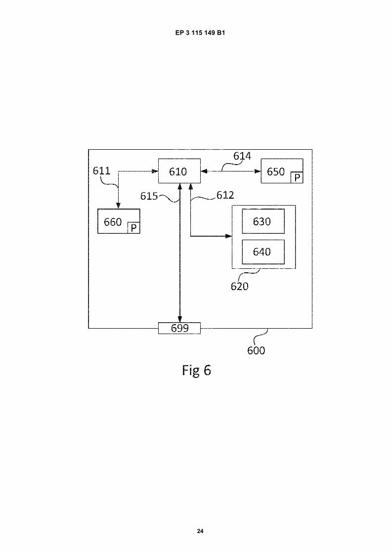
Fig. 6 schematically illustrates a device comprising a computer programme according to an embodiment.
Detailed description
[0029] In the following, the invention will be described in more detail with reference to the drawings. However, theinvention is not limited to the embodiments disclosed and discussed but may be varied within the scope of the appendedclaims. Furthermore, the drawings shall not be considered drawn to scale as some features may be exaggerated inorder to more clearly illustrate the features.[0030] Furthermore, the workpiece is in the following sometimes exemplified by a crankpin. The workpiece and thegrinding method is however not limited to grinding of a crankpin and the workpiece may be any workpiece having acylindrical bearing surface, a radially extending sidewall and a curved transition portion having a radius and connectingthe cylindrical bearing surface with the sidewall. Typically, the workpiece comprises two radially extending sidewallsextending outward from the cylindrical bearing surface and each connected to the cylindrical bearing surface by a curvedtransition portion.[0031] The present disclosure relates to grinding of a workpiece by means of a grinding wheel. The workpiece comprisesa cylindrical bearing surface arranged around a centre axis. At an axial end of the cylindrical bearing surface, theworkpiece comprises a radially extending sidewall which extends radially outward from the cylindrical bearing surfacearound the whole circumference of the cylindrical bearing surface. The cylindrical bearing surface is connected to thesidewall by means of a surface constituting a curved transition portion having a radius. As previously disclosed, Figures1 a and 1b illustrates an example of such a workpiece.[0032] The grinding wheel is essentially rotationally symmetrical around a rotational axis thereof, and is rotated aroundsaid rotational axis. The rotational axis of the grinding wheel is essentially parallel to the centre axis of the cylindricalbearing surface. Therefore, the radially peripheral surface of the grinding wheel will grind the cylindrical bearing surfacewhereas the axial peripheral surface of the grinding wheel will grind the sidewall of the workpiece. The grinding wheel

EP 3 115 149 B1
6
5
10
15
20
25
30
35
40
45
50
55
has a width, i.e. axial extension, which is smaller than the axial extension of the cylindrical bearing surface.[0033] The present invention is based on an in-depth investigation to understand the complex mechanisms that ariseat the interface between the grinding wheel and the workpiece at the cylindrical bearing surface, the sidewall and thecurved transition portion connecting the cylindrical bearing surface with the sidewall, in terms of fundamental grindingparameters. These fundamental grinding parameters are: contact length between the workpiece and the grinding wheel(lc,), specific material removal rate (Q’w), aggressiveness number (aggr), grinding power (Pg), and maximum surfacetemperature of the workpiece (θm). Based on the modelling, a strategy of the grinding method has been developed. Thestrategy is provided to achieve an essentially constant-temperature process that yields the shortest cycle time that canbe achieved within temperature thresholds to avoid thermal damages of the workpiece.[0034] The temperature limit to avoid thermal damage, of the workpiece depends on the material of the workpieceand the heat treatment process. The temperature limits may be determined via measured Barkhausen noise signals,measured residual stress values versus depth into the material, thermal softening from hardness measurements versusdepth into the material, and rehardening burn by sectioning and examining for "white layer" (consisting of untemperedmartensite and retained austenite, resulting from phase transformations in the material of the workpiece) in order to"calibrate" Barkhausen noise signals to determine the thresholds for grinding without thermally damaging the workpiece.Then, these Barkhausen noise threshold values may be correlated with the simulated temperatures by the model, whichwill be further disclosed below, to determine processing parameters for grinding needed to avoid risk for thermal damageof the workpiece.[0035] It has been found that an optimal strategy for the grinding method is a unique version of angle-plunge grinding(also known as vector grinding), utilizing the inherently better approach of angle-plunge grinding, and avoiding theproblem of selecting inputs based on trial-and-error. However, the model developed may also be used if utilising otherstrategies for grinding, for example grinding methods utilising radial plunge followed by axial plunge.[0036] The model developed in accordance with the present invention may be embedded into a simulation tool, i.e. acomputer programme for determining processing parameters, that is used to visualize the fundamental grinding param-eters, i.e. contact length between the workpiece and the grinding wheel, specific material removal rate, aggressivenessnumber, grinding power and maximum surface temperature at all points on the grinding wheel profile for a selectedgrinding increment.[0037] During grinding of a workpiece, such as a workpiece as previously described, the instantaneous specific materialremoval rate, the aggressiveness number and specific energy (i.e. the energy per unit volume of material removal)change not only along the contact length from the cylindrical bearing surface, through the curved transition portion andup the sidewall, but the actual instantaneous contact length changes throughout the process as well. In addition, whatthe grinding wheel "sees" changes due to the changing three-dimensional surface along the radius of the curved transitionportion and through the arc of contact. This complex geometry has not previously been modelled and analysed, andtrying to analyse all three portions (the cylindrical bearing surface, the curved transition portion and the sidewall) canprove very difficult as the conditions change drastically just a short distance between points of the grinding wheel surfacein contact with the workpiece.[0038] In order to overcome these difficulties, an analytical approach has been taken to model the geometry andkinematics of the instantaneous grinding situation, taking every point of the grinding wheel surface individually andconsidering it as a separate entity from adjacent points on the grinding wheel surface. In this way, the fundamentalgrinding parameters in terms of contact length, specific material removal rate, aggressiveness number, grinding powerand maximum surface temperature can be explicitly determined at each point without making assumptions. Based onsuch an approach, the grinding parameters for the whole grinding cycle can be optimised based on the most criticalpoint of the grinding wheel at each moment, i.e. the point of the grinding wheel which at a specific condition and pointof time would cause the highest risk for thermal damage of the workpiece.[0039] Figure 2 schematically illustrates how the relative workpiece velocity, vw, which constitutes the fundamentalkinematical grinding parameter needed for modelling, is derived. More specifically, Figure 2 schematically illustrates ageneralised case of workpiece grinding kinematics, where the workpiece angular speed, ω, is modelled around theworkpiece (i.e. it is here assumed for the sake of modelling that the wheel moves around the workpiece), and thusillustrates a geometrical and kinematical framework for a functional determination of the relative workpiece velocity, vw.The workpiece may for example be a crankpin 2 as shown in Figures 1 a and 1b and for sake of clarity the workpiecewill in the following be exemplified by such a crankpin 2 of a crankshaft.[0040] As shown in Figure 2, the workpiece has a radius, rw, from a central axis 3b of the cylindrical bearing surface3 to the peripheral surface thereof 3a, and the grinding wheel 6 has a radius, rs, from its rotational centre 6b to theperipheral surface 6a thereof. The crankshaft 1 comprising the crankpin 2 has a rotational axis A. Thus, there is a distancedws(ϕws) between the rotational axis A of the crankshaft and the rotational axis 6b of the grinding wheel, wherein theangle ϕws constitutes the independent variable used. The eccentricity of the crankpin relative to the rotational axis A isdenominated eccw.[0041] For a modelling purpose, considering a fixed crankshaft, the kinematics of the grinding wheel relatively to the
EP 3 115 149 B1
7
5
10
15
20
25
30
35
40
45
50
55
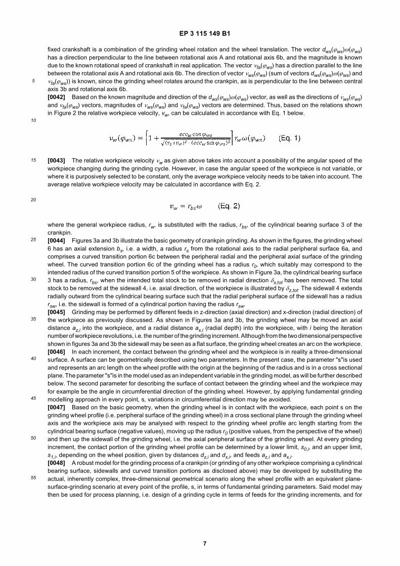
fixed crankshaft is a combination of the grinding wheel rotation and the wheel translation. The vector dws(ϕws)ω(ϕws)has a direction perpendicular to the line between rotational axis A and rotational axis 6b, and the magnitude is knowndue to the known rotational speed of crankshaft in real application. The vector νfa(ϕws) has a direction parallel to the linebetween the rotational axis A and rotational axis 6b. The direction of vector νws(ϕws) (sum of vectors dws(ϕws)ω(ϕws) andνfa(ϕws)) is known, since the grinding wheel rotates around the crankpin, as is perpendicular to the line between centralaxis 3b and rotational axis 6b.[0042] Based on the known magnitude and direction of the dws(ϕws)ω(ϕws) vector, as well as the directions of νws(ϕws)and νfa(ϕws) vectors, magnitudes of νws(ϕws) and νfa(ϕws) vectors are determined. Thus, based on the relations shownin Figure 2 the relative workpiece velocity, vw, can be calculated in accordance with Eq. 1 below.
[0043] The relative workpiece velocity νw as given above takes into account a possibility of the angular speed of theworkpiece changing during the grinding cycle. However, in case the angular speed of the workpiece is not variable, orwhere it is purposively selected to be constant, only the average workpiece velocity needs to be taken into account. Theaverage relative workpiece velocity may be calculated in accordance with Eq. 2.
where the general workpiece radius, rw, is substituted with the radius, rbs, of the cylindrical bearing surface 3 of thecrankpin.[0044] Figures 3a and 3b illustrate the basic geometry of crankpin grinding. As shown in the figures, the grinding wheel6 has an axial extension bs, i.e. a width, a radius rs from the rotational axis to the radial peripheral surface 6a, andcomprises a curved transition portion 6c between the peripheral radial and the peripheral axial surface of the grindingwheel. The curved transition portion 6c of the grinding wheel has a radius r0, which suitably may correspond to theintended radius of the curved transition portion 5 of the workpiece. As shown in Figure 3a, the cylindrical bearing surface3 has a radius, rbs, when the intended total stock to be removed in radial direction δx,tot has been removed. The totalstock to be removed at the sidewall 4, i.e. axial direction, of the workpiece is illustrated by δz,tot. The sidewall 4 extendsradially outward from the cylindrical bearing surface such that the radial peripheral surface of the sidewall has a radiusrsw, i.e. the sidewall is formed of a cylindrical portion having the radius rsw.[0045] Grinding may be performed by different feeds in z-direction (axial direction) and x-direction (radial direction) ofthe workpiece as previously discussed. As shown in Figures 3a and 3b, the grinding wheel may be moved an axialdistance az,i into the workpiece, and a radial distance ax,i (radial depth) into the workpiece, with i being the iterationnumber of workpiece revolutions, i.e. the number of the grinding increment. Although from the two dimensional perspectiveshown in figures 3a and 3b the sidewall may be seen as a flat surface, the grinding wheel creates an arc on the workpiece.[0046] In each increment, the contact between the grinding wheel and the workpiece is in reality a three-dimensionalsurface. A surface can be geometrically described using two parameters. In the present case, the parameter "s"is usedand represents an arc length on the wheel profile with the origin at the beginning of the radius and is in a cross sectionalplane. The parameter "s"is in the model used as an independent variable in the grinding model, as will be further describedbelow. The second parameter for describing the surface of contact between the grinding wheel and the workpiece mayfor example be the angle in circumferential direction of the grinding wheel. However, by applying fundamental grindingmodelling approach in every point, s, variations in circumferential direction may be avoided.[0047] Based on the basic geometry, when the grinding wheel is in contact with the workpiece, each point s on thegrinding wheel profile (i.e. peripheral surface of the grinding wheel) in a cross sectional plane through the grinding wheelaxis and the workpiece axis may be analysed with respect to the grinding wheel profile arc length starting from thecylindrical bearing surface (negative values), moving up the radius r0 (positive values, from the perspective of the wheel)and then up the sidewall of the grinding wheel, i.e. the axial peripheral surface of the grinding wheel. At every grindingincrement, the contact portion of the grinding wheel profile can be determined by a lower limit, s0,i, and an upper limit,s1,i, depending on the wheel position, given by distances dz,i and dx,i, and feeds az,i and ax,i.[0048] A robust model for the grinding process of a crankpin (or grinding of any other workpiece comprising a cylindricalbearing surface, sidewalls and curved transition portions as disclosed above) may be developed by substituting theactual, inherently complex, three-dimensional geometrical scenario along the wheel profile with an equivalent plane-surface-grinding scenario at every point of the profile, s, in terms of fundamental grinding parameters. Said model maythen be used for process planning, i.e. design of a grinding cycle in terms of feeds for the grinding increments, and for

EP 3 115 149 B1
8
5
10
15
20
25
30
35
40
45
50
55
simultaneous process optimisation, i.e. minimising the grinding cycle time.[0049] In accordance with the present invention, modelling of the grinding geometry is performed by determination ofsimplified relations between axial and radial feeds (az, ax), corresponding depth of cut, ae, and contact length, lc, at thecylindrical bearing surface (Eq. 3 and Eq. 4), the curved transition portion (Eq. 5 and Eq. 6) and the sidewall of theworkpiece (Eq. 7 and Eq. 8). More specifically:
• At cylindrical bearing surface; s ≤ 0:
• At curved transition portion of workpiece;
• At sidewall of workpiece;
[0050] In the equations above, req, is the equivalent radius and is defined by Eq. 9.
[0051] Based on the modelling approach described above, the fundamental grinding parameters specific material
removal rate aggressiveness number aggr, grinding power Pg and maximum surface temperature θm can be
calculated as given below by Eq. 10 to Eq. 13 in every point s of the grinding wheel profile.

EP 3 115 149 B1
9
5
10
15
20
25
30
35
40
45
50
55
[0052] In Eq. 11, vs is the grinding wheel speed. In Eq. 13, k is the thermal conductivity, p the density, and cp thespecific heat of the workpiece material.[0053] A core part of thermal modelling is the determination of the specific energy into the workpiece characteristic(versus aggressiveness number), ew(aggr), which is based on the total specific energy characteristic, etot(aggr), and thethermal model.[0054] The total specific energy characteristic, etot(aggr), may be obtained from grinding experiments, where grindingpower is measured for various feeds. The experiments may suitably be conducted in two separate stages, i) sidewallgrinding where only axial feed is used and ii) cylindrical bearing surface grinding where only radial feed is used. Thetotal specific energy characteristic is given below with reference from Eq. 14 to Eq. 18.
• Low aggressiveness - side wall grinding; aggr ≤ aggr0z:
where aggr0z, is the optimal aggressiveness for sidewall grinding.• High aggressiveness - cylindrical bearing surface grinding; aggr ≥ aggr0x:
where aggr0x is the optimal aggressiveness for bearing-surface grinding.• Transition region; aggr0z < aggr < aggr0x:
Based on exponential interpolation:
[0055] The coefficients c1,c2 and c3 are determined in order to get continuous and smooth total specific energy char-acteristic.[0056] Constants of the characteristic e0z, Cz, e0x, Cx are obtained with approximation of the measured results by theleast-square method, while the exponents in the expressions are chosen as: mz = 1 and mx = 3/2, in order to get a finitevalue when the depth of cut approaches zero value.[0057] The specific energy into the workpiece characteristic, ew(aggr), is then determined by calculating energy partitionratios, εz and εx, for each grinding type separately. Calculations are based on the use of the thermal model combinedwith the measured Barkhausen noise signals, which are correlated with certain maximum surface temperature values.In this way, the specific energy into the workpiece characteristic is obtained based on the total specific energy charac-teristic as given below with reference from Eq. 19 to Eq.21.
• Low aggressiveness - side wall grinding; aggr ≤ aggr0z:
• High aggressiveness - cylindrical bearing surface grinding; aggr ≥ aggr0x:

EP 3 115 149 B1
10
5
10
15
20
25
30
35
40
45
50
55
• Transition region; aggr0z, < aggr < aggr0x:
Based on continuous and smooth exponential interpolation:
[0058] By using the model as described above, grinding of a workpiece comprising a cylindrical bearing surface, aradial sidewall and a curved transition portion connecting the cylindrical bearing surface with the sidewall can be optimisedas disclosed below. The grinding method is optimised by determining axial and radial feeds (az and ax) within eachincrement, necessary to grind the workpiece at a set maximum surface temperature, thereby also obtaining the numberof increments needed (which inherently also is the lowest possible for the grinding cycle). The lowest number of grindingincrements gives the minimum grinding cycle time. By controlling the method so that the set maximum surface temperatureis not exceeded at any point on the contact between the workpiece and the grinding wheel, there is no risk for thermaldamage of the workpiece during grinding.[0059] Based on the above, a method for determining grinding parameters may be achieved. Thus, the present inventionprovides a method of determining processing parameters of a grinding method for grinding a workpiece by means of anessentially rotational symmetrical grinding wheel, the workpiece comprising a cylindrical bearing surface 3, a radiallyextending sidewall 4 extending outward from the cylindrical bearing surface, and a curved transition portion 5 connectingthe cylindrical bearing surface with the sidewall, wherein the grinding wheel has an axial extension less than the axialextension of the cylindrical bearing surface, the method comprising, based on a pre-set maximum surface temperature,determining a number of increments and the respective axial feed and radial feed of said increments. The methodcomprises the following steps:
a) based on a position of the grinding wheel at the end of the grinding cycle, determining the distance into theworkpiece in radial respectively axial direction and hence determine the corresponding contact portion set by a lowerlimit and an upper limit (of the grinding wheel profile;b) determining an axial feed and a radial feed, in a corresponding increment, necessary to keep the pre-set maximumsurface temperature at a point of the contact portion of the grinding wheel resulting in a highest surface temperatureof the workpiece during said corresponding increment;c) based on the axial feed and the radial feed determined in step b) determining the resulting grinding wheel positionafter completion of one increment with said axial feed and radial feed,d) based on the grinding wheel position obtained in step c) determining a corresponding contact portion with acorresponding lower limit and upper limit of the grinding wheel profile;e) in case the lower limit of the contact portion is less than the upper limit of the contact portion obtained in step d)repeating steps b) to d) until the lower contact limit of the contact portion is not less than the upper limit;f) indexing the obtained increments and their respective axial feed and radial feed according to the grinding process.
[0060] Figure 4 illustrates a first exemplifying embodiment of such a method for determining grinding parameters. Themethod comprises, based on system and thermal inputs 400, determining the outputs 406 constituting the number ofincrements, n, and the axial feed az,i and radial feed ax,i in each of the increments, i = 1, 2 ... n.[0061] In accordance with the method, the calculation of feeds starts at the final wheel position, i.e. when dz = δz,totand dx = rsw - rbs + δx,tot, and moves backwards to the initial position of the grinding wheel just before the beginning ofgrinding. Both total grinding allowances, δz,tot and δx,tot, may include a certain offset needed to compensate for a possiblerun-out in the incoming workpiece dimensions.[0062] Thus, based on the wheel position at end of grinding and the corresponding distance into the workpiece asdefined by dz,j and dx,j, the corresponding contact portion set by a lower limit s0,j and an upper limit s1,j of the grindingwheel is determined, 401.[0063] The central part of the method is a constant-temperature process, where the axial feed, az,j, and radial feed,ax,j, needed to keep the pre-set maximum surface temperature at a point of the contact portion of the grinding wheelresulting in a highest surface temperature of the workpiece, while achieving maximum material removal rate, Qw,j, duringsuch an increment, is determined, 402.
[0064] First, the limit depth of cut, is calculated as a function of wheel profile position, s, in order to match the

EP 3 115 149 B1
11
5
10
15
20
25
30
35
40
45
50
55
pre-set maximum surface temperature, θ*. For this purpose, the thermal model is written in the following form (Eq. 22):
which includes grinding parameters as functions of both wheel profile position and limit depth of cut.
[0065] That is, the limit depth of cut is calculated in every point s of the wheel profile, regardless of a grinding
increment j and contact portion limits s0,j and s1,j. This means that is only one function for all increments and
can be calculated in advance for given pre-set temperature θ*. In other words, function represents the pre-set temperature (which has the same value for all points s) translated into the limit depth of cut (which is, because ofchanging geometry, a different value in every point s).[0066] Next, the algorithm determines the axial feed, az,j, and radial feed, ax,j, in a way that:
• the pre-set maximum surface temperature is not exceeded in the wheel-profile contact portion, which in terms ofdepth-of-cut reads in accordance with Eq. 23:
• maximum material removal rate, which is calculated in accordance with Eq. 24:
is achieved in the current grinding increment, j.
[0067] If the limit depth of cut function would be used in every point s, the pre-set maximum surface temperature wouldbe achieved at every point s. However, only the feeds az,j and ax,j are used in order to adjust in a current increment.
This means that the pre-set temperature can only be achieved in two points s of the contact portion in the currentincrement. Therefore, two critical points of the limit depth of cut function should be selected in the current contact interval.In other words, the values of az,j and ax,j are to be determined in such a way as to match the pre-set maximum surface
temperature θ* only in two points of the contact interval (scr1,j and scr2,j). Everywhere else the actual depth of cut is lower
than the limit depth of cut in those points, since the critical two values of is used for calculation of az,j and ax,j, and
hence the surface temperature of the workpiece will be lower than the pre-set maximum surface temperature.[0068] Thus, in accordance with the present invention the algorithm then choses two critical points of the calculatedlimit-depth-of-cut function in the current grinding increment. Candidates for those two points are the ones in the currentcontact interval that simultaneously fulfil the conditions given by Eq. 23 and Eq. 24. The two critical points are furtherused to determine the corresponding axial and radial feeds as:
where and
[0069] Next, the new wheel position is determined by reducing for the calculated feeds, and hence the new wheel-profile contact limits are determined, 403.[0070] The algorithm continues with the calculations until there is no contact between the wheel and the crankpin,

EP 3 115 149 B1
12
5
10
15
20
25
30
35
40
45
50
55
404. In the final stage, the number of grinding increments is determined and the calculated feeds are indexed accordingto the grinding process, 405.[0071] Figure 5 illustrates a second exemplifying embodiment of a method for determining grinding parameters. Thesecond exemplifying embodiment corresponds to the exemplifying embodiment as shown in Figure 4 except that it
provides the possibility to set two input surface temperatures, and 500. The first set temperature, can be
higher than in order to have an additional possibility to even further reduce the grinding cycle time, because it is used
to control the first grinding portion, which is related to the defined amount of axial grinding allowance, δz,1. In this first
grinding portion, the process planer has the possibility to set a higher to induce slight thermal damage into the
workpiece (e.g. slight tensile residual stresses) in a controlled way if grinding cycle time is crucial. Then, in the secondgrinding portion, which is the final one, the remaining allowance, i.e. δz,tot - δz,1, is ground with a lower set temperature
to improve quality (surface integrity) of the ground workpiece surface without any thermal damage. When choosing
a high the process planner needs to be careful that the depth of eventual thermal damage into the workpiece is
lower than the remaining allowance θz,tot - θz,1.
[0072] The grinding method is not limited to the specific embodiments described above but may be varied within thescope of the appended claims. For example, grinding may be performed with a constant or non-constant rotational speedof the workpiece during each increment. Furthermore, the rotational speed of the workpiece in one increment may bedifferent from a rotational speed of the workpiece in a subsequent increment if desired. Moreover, the grinding methodmay for example be an angle-plunge grinding method, or a combined radial and axial plunge grinding method whereinfor the majority of the process the grinding wheel is plunged radially into the workpiece. Other types of grinding processesare also feasible.[0073] Furthermore, the grinding method as disclosed herein can be used on a conventional grinding machine orapparatus used for the same purpose and is not limited to certain grinding machines or the like.[0074] Figure 6 is a diagram of an exemplified device 600. An electronic control unit of a grinding machine may forexample comprise the exemplified device 600 or the device may be a separate unit from the grinding machine. Thedevice 600 comprises a non-volatile memory 620, a data processing unit 610 and a read/write memory 650. The non-volatile memory 620 has a first memory element 630 in which a computer programme, e.g. an operating system, isstored for controlling the function of the device 600. The device 600 may further comprise a bus controller, a serialcommunication port, I/O means, an A/D converter, a time and date input and transfer unit, an event counter and aninterruption controller (not depicted). The non-volatile memory 620 has also a second memory element 640.[0075] There is a computer programme P provided which comprises routines for determining processing parameters,more specifically number of increments and feed in each of the increments, of a grinding method for grinding a workpieceby means of an essentially rotational symmetrical grinding wheel, wherein the processing parameters are determined by:
a) based on a position of the grinding wheel at the end of the grinding cycle, determining the distance into theworkpiece in radial respectively axial direction and hence determine the corresponding contact portion set by a lowerlimit and an upper limit (of the grinding wheel profile;b) determining an axial feed and a radial feed, in a corresponding increment, necessary to keep the pre-set maximumsurface temperature at a point of the contact portion of the grinding wheel resulting in a highest surface temperatureof the workpiece during said corresponding increment;c) based on the axial feed and the radial feed determined in step b) determining the resulting grinding wheel positionafter completion of one increment with said axial feed and radial feed,d) based on the grinding wheel position obtained in step c) determining a corresponding contact portion with acorresponding lower limit and upper limit of the grinding wheel profile;e) in case the lower limit of the contact portion is less than the upper limit of the contact portion obtained in step d)repeating steps b) to d) until the lower contact limit of the contact portion is not less than the upper limit;f) indexing the obtained increments and their respective axial feed and radial feed according to the grinding process.
[0076] The computer programme may further be arranged to provide the determined processing parameters to anelectronic control unit or another computer connected to or adapted to communicate with the electronic control unit.[0077] The computer programme may be stored in an executable form in a compressed form in a memory 660 and/orin a read/write memory 650.[0078] Where the data processing unit 610 is described as performing a certain function, it means that the dataprocessing unit 610 effects a certain part of the programme stored in the memory 660, or a certain part of the programmestored in the read/write memory 650.[0079] The data processing device 610 can communicate with a data port 699 via a data bus 615. The non-volatile

EP 3 115 149 B1
13
5
10
15
20
25
30
35
40
45
50
55
memory 620 is intended for communication with the data processing unit 610 via a data bus 612. The separate memory660 is intended to communicate with the data processing unit 610 via a data bus 611. The read/write memory 650 isadapted to communicate with the data processing unit 610 via a data bus 614.[0080] When data are received on the data port 699, they are stored temporarily in the second memory element 640.When input data received have been temporarily stored, the data processing unit 610 is prepared to effect code executionas described above.[0081] Parts of the methods herein described may be affected by the device 600 by means of the data processingunit 610 which runs the programme stored in the memory 660 or the read/write memory 650. When the device 600 runsthe programme, methods herein described are executed.[0082] The foregoing description of the exemplified embodiments of the present invention is provided for illustrativeand descriptive purposes. It is not intended to be exhaustive or to restrict the invention to the variants described. Manymodifications and variations will obviously be apparent to one skilled in the art. The embodiments have been chosenand described in order best to explain the principles of the invention and its practical applications and hence make itpossible for specialists to understand the invention for various embodiments and with the various modifications appro-priate to the intended use.
Claims
1. Method of grinding a workpiece by means of an essentially rotational symmetrical grinding wheel (6), the workpiececomprising a cylindrical bearing surface (3), a radially extending sidewall (4) extending outward from the cylindricalbearing surface, and a curved transition portion (5) connecting the cylindrical bearing surface with the sidewall,wherein the grinding wheel has an axial extension less than the axial extension of the cylindrical bearing surface,the method comprising grinding the workpiece in a plurality of grinding increments together defining a grinding cycle,each grinding increment performed with a respective feed of the grinding wheel in relation to the workpiece, char-acterised in that, in each grinding increment, the feed is selected so as to achieve a pre-set maximum surfacetemperature of the workpiece at a point of the grinding wheel resulting in the highest surface temperature of theworkpiece.
2. Method according to claim 1, wherein the feed comprises an axial feed and a radial feed, and the axial feed andthe radial feed are independently selected so as to achieve said pre-set maximum surface temperature of theworkpiece at the contact point of the grinding wheel resulting in the highest surface temperature of the workpiece.
3. Method according to any of the preceding claims, wherein the grinding wheel is rotated with a constant rotationalspeed throughout the grinding cycle.
4. Method according to any of the preceding claims, wherein the workpiece is rotated with a constant rotational speedthroughout the grinding cycle.
5. Method according to any of the preceding claims, wherein the workpiece is a crankpin (2) of a crankshaft (1).
6. Method of determining processing parameters of a grinding method for grinding a workpiece by means of an es-sentially rotational symmetrical grinding wheel (6) having a grinding wheel profile, the workpiece comprising acylindrical bearing surface (3), a radially extending sidewall (4) extending outward from the cylindrical bearingsurface, and a curved transition portion (5) connecting the cylindrical bearing surface with the sidewall, wherein thegrinding wheel has an axial extension less than the axial extension of the cylindrical bearing surface, the methodcomprising based on a pre-set maximum surface temperature (θ*) determining a number of increments (n) and therespective axial feed (az,i) and radial feed (ax,i) of said increments, the method comprising the following steps:
a) based on a position of the grinding wheel at the end of the grinding cycle, determining the distance (dz,j, dx,j)into the workpiece in radial respectively axial direction and hence determine the corresponding contact portionset by a lower limit (s0,j) and an upper limit (S1,j) of the grinding wheel profile (401);b) determining an axial feed (az,j) and a radial feed (ax,j), in a corresponding increment, necessary to keep thepre-set maximum surface temperature (θ*) at a point of the contact portion of the grinding wheel resulting in ahighest surface temperature of the workpiece (402) during said corresponding increment;c) based on the axial feed (az,j) and the radial feed (ax,j) determined in step b) determining the resulting grindingwheel position after completion of one increment with said axial feed and radial feed,d) based on the grinding wheel position obtained in step c) determining a corresponding contact portion with a

EP 3 115 149 B1
14
5
10
15
20
25
30
35
40
45
50
55
corresponding lower limit and upper limit of the grinding wheel profile (403);e) in case the lower limit of the contact portion is less than the upper limit of the contact portion obtained in stepd) repeating steps b) to d) until the lower contact limit of the contact portion is not less than the upper limit (404);f) indexing the obtained increments (i) and their respective axial feed and radial feed according to the grindingprocess (405).
7. The method according to claim 6, wherein determining the axial feed (az,j) and a radial feed (ax,j) necessary to keepthe pre-set maximum surface temperature (θ*) at a point of the contact portion of the grinding wheel resulting in ahighest surface temperature of the workpiece in step b) is performed such as to achieve a maximum material removalrate in the corresponding increment.
8. The method according to any of claims 6 or 7, wherein the axial feed and radial feed are determined in step b) by
calculating a limit depth of cut as a function of the grinding wheel profile position (s) in order to match the pre-
set maximum surface temperature (θ*), selecting two critical points of the limit depth of cut function (scr1, scr2) in the
current contact interval, and using the two critical points to determine the corresponding axial feed and radial feed.
9. The method according to claim 8, wherein the limit depth of cut function is given by the following equation (Eq.22)
wherein θ* is the pre-set maximum surface temperature, k is the thermal conductivity of the workpiece material, ρthe density of the workpiece material, cp is the specific heat of the workpiece material, ew is the specific energy intothe workpiece, νs is the grinding wheel speed, and aggr is the aggressiveness number.
10. Method according to claim 9, wherein the total specific energy characteristic, etot(aggr), is obtained from grindingpower measurements performed in a first step comprising only sidewall grinding wherein only axial feed is used,and a second step comprising only cylindrical bearing surface grinding wherein only radial feed is used, and whereinthe total specific energy in the transition region is obtained by exponential interpolation; and wherein the specificenergy into the workpiece characteristic ew(aggr) is determined by calculating energy partition ratios and applyingthem to the total specific energy characteristic for each grinding type separately, and wherein the specific energyin the transition region is again obtained by exponential interpolation.
11. Computer programme (P) for determining processing parameters of a grinding method, wherein said computerprogramme comprises programme code for performing the method steps of any of claims 6 to 10.
12. Computer programme according to claim 11, further arranged to provide said determined processing parametersto an electronic control unit or another computer connected to or adapted to communicate with the electronic controlunit.
13. Computer programme product containing programme code stored on a computer-readable medium for performingthe method according to any of claims 6 to 10, wherein said computer programme is run on an electronic controlunit or another computer connected to or adapted to communicate with the electronic control unit.
Patentansprüche
1. Verfahren zum Schleifen eines Werkstücks mittels einer im Wesentlichen rotationssymmetrischen Schleifscheibe(6), wobei das Werkstück eine zylindrische Lagerfläche (3), eine sich radial erstreckende Seitenwand (4), die sichaus der zylindrischen Lagerfläche nach außen erstreckt, und einen gekrümmten Übergangsabschnitt (5) aufweist,der die zylindrische Lagerfläche mit der Seitenwand verbindet, wobei die Schleifscheibe eine axiale Erstreckunghat, die kleiner ist als die axiale Erstreckung der zylindrischen Lagerfläche, wobei das Verfahren das Schleifen desWerkstücks in einer Mehrzahl Schleifinkrementen, die zusammen einen Schleifzyklus definieren, aufweist, wobeijedes Schleifinkrement mit einem entsprechenden Vorschub der Schleifscheibe relativ zum Werkstück ausgeführtwird,dadurch gekennzeichnet, dass in jedem Schleifinkrement der Vorschub so gewählt wird, dass eine voreingestellte

EP 3 115 149 B1
15
5
10
15
20
25
30
35
40
45
50
55
maximale Oberflächentemperatur des Werkstücks an einem Punkt der Schleifscheibe erzielt wird, die in der höchstenOberflächentemperatur des Werkstücks resultiert.
2. Verfahren nach Anspruch 1, wobei der Vorschub einen axialen Vorschub und einen radialen Vorschub aufweistund der axiale Vorschub sowie der radiale Vorschub unabhängig gewählt werden, um die voreingestellte maximaleOberflächentemperatur des Werkstücks am Kontaktpunkt der Schleifscheibe zu erzielen, die in der höchsten Ober-flächentemperatur des Werkstücks resultiert.
3. Verfahren nach einem der vorigen Ansprüche, wobei sich die Schleifscheibe während des gesamten Schleifzyklusmit einer konstanten Rotationsgeschwindigkeit dreht.
4. Verfahren nach einem der vorigen Ansprüche, wobei sich das Werkstück während des gesamten Schleifzyklus miteiner konstanten Rotationsgeschwindigkeit dreht.
5. Verfahren nach einem der vorigen Ansprüche, wobei das Werkstück ein Kurbelzapfen (2) einer Kurbelwelle (1) ist.
6. Verfahren zum Bestimmen von Bearbeitungsparametern eines Schleifverfahrens zum Schleifen eines Werkstücksmittels einer im Wesentlichen rotationssymmetrischen Schleifscheibe (6) mit einem Schleifscheibenprofil, wobeidas Werkstück eine zylindrische Lagerfläche (3), eine sich aus der zylindrischen Lagerfläche radial nach außenerstreckende Seitenwand (4) und einen gekrümmten Übergangsabschnitt (5) aufweist, der die zylindrische Lager-fläche mit der Seitenwand verbindet, wobei die Schleifscheibe eine axiale Erstreckung hat, die kleiner ist als dieaxiale Erstreckung der zylindrischen Lagerfläche, wobei das Verfahren die Bestimmung einer Anzahl Inkremente(n) und des jeweiligen axialen Vorschubs (az,i) sowie des radialen Vorschubs (ax,i) der Inkremente auf Basis einervoreingestellten maximalen Oberflächentemperatur (θ*) aufweist, wobei das Verfahren die Schritte aufweist:
a) Bestimmen der Strecke (dz,j), (dx,j) in das Werkstück in radialer bzw. axialer Richtung und somit Bestimmendes durch einen unteren Grenzwert (s0,j) und einen oberen Grenzwert (s1,j) des Schleifscheibenprofils (401)eingestellten entsprechenden Kontaktabschnitts auf Basis einer Position der Schleifscheibe am Ende desSchleifzyklus;b) Bestimmen eines axialen Vorschubs (az,i) und eines radialen Vorschubs (ax,i) in einem entsprechendenInkrement, die erforderlich sind, um die voreingestellte maximale Oberflächentemperatur (θ*) an einem Punktdes Kontaktabschnitts der Schleifscheibe aufrechtzuerhalten, was in der höchsten Oberflächentemperatur desWerkstücks (402) während des entsprechenden Inkrements resultiert;c) Bestimmen der resultierenden Schleifscheibenposition nach Beendigung eines Inkrements bei dem axialenVorschub und dem radialen Vorschub auf Basis des in Schritt b) bestimmten axialen Vorschubs (az,i) und desradialen Vorschubs (ax,i),d) Bestimmen eines entsprechenden Kontaktabschnitts mit einem entsprechenden unteren Grenzwert undeinem oberen Grenzwert des Schleifscheibenprofils auf Basis der in Schritt c) bestimmten Schleifscheibenpo-sition (403);e) Wiederholen der Schritte b) bis d), falls der untere Grenzwert des Kontaktabschnitts niedriger ist als der inSchritt d) erhaltene obere Grenzwert des Kontaktabschnitts, bis der untere Grenzwert des Kontaktabschnittsnicht mehr niedriger ist als der obere Grenzwert (404);f) Indexieren der erhaltenen Inkremente (i) sowie ihres entsprechenden axialen Vorschubs und radialen Vor-schubs gemäß dem Schleifprozess (405).
7. Verfahren nach Anspruch 6, wobei die Bestimmung des axialen Vorschubs (az,i) und des radialen Vorschubs (ax,i),die erforderlich sind, um die voreingestellte maximale Oberflächentemperatur (θ*) an einem Punkt des Kontaktab-schnitts der Schleifscheibe aufrechtzuerhalten, die in der höchsten Oberflächentemperatur des Werkstücks in Schrittb) so erfolgt, dass eine maximale Materialabtragungsgeschwindigkeit im entsprechenden Inkrement erzielt wird.
8. Verfahren nach einen der Ansprüche 6 oder 7, wobei der axiale Vorschub und der radiale Vorschub durch Berechnung
einer Begrenzung der Schnitttiefe als eine Funktion der Schleifscheibenprofilposition (s) in Schritt b), um die
voreingestellte maximale Oberflächentemperatur (θ*) anzupassen, durch Wählen zweier kritischer Punkte derSchnitttiefenbegrenzungsfunktion (scr1, scr2) im aktuellen Kontaktintervall und durch Verwenden der zwei kritischen
Punkte zur Bestimmung des entsprechenden axialen und radialen Vorschubs bestimmt werden.
9. Verfahren nach Anspruch 8, wobei die Schnitttiefenbegrenzungsfunktion durch die folgende Gleichung gegeben

EP 3 115 149 B1
16
5
10
15
20
25
30
35
40
45
50
55
ist: (Gleichung 22)
dabei ist (θ*) die voreingestellte maximale Oberflächentemperatur, k ist die Wärmeleitfähigkeit des Werkstückma-terials, p die Dichte des Werkstückmaterials, cp ist die spezifische Wärme des Werkstückmaterials, ew ist die spe-zifische Energie die in das Werkstückmaterial eingebracht wird, vs ist die Schleifscheibengeschwindigkeit und aggrist die Aggressivitätszahl.
10. Verfahren nach Anspruch 9, wobei der spezifische Gesamtenergiekennwert etot(aggr) aus den Schleifkraftmessun-gen erhalten wird, die in einem ersten Schritt, bei dem nur Seitenwandschleifen mit nur axialem Vorschub angewendetwird, und in einem zweiten Schritt, in dem nur Schleifen der zylindrischen Lagerfläche mit nur radialem Vorschubangewendet wird, ausgeführt werden, und wobei die spezifische Gesamtenergie im Übergangsbereich durch ex-ponentielle Interpolation erhalten wird; und wobei die in den Werkstückkennwert ew(aggr) eingegangene spezifischeEnergie durch Berechnen und Anwenden von Energieverteilungsverhältnissen auf den spezifischen Gesamtener-giekennwert für jeden Schleiftyp getrennt bestimmt wird, und wobei die spezifische Energie im Übergangsbereichwieder durch exponentielle Interpolation erhalten wird.
11. Computerprogramm (P) zur Bestimmung von Bearbeitungsparametern eines Schleifverfahrens, wobei das Com-puterprogramm einen Programmcode zum Ausführen der Verfahrensschritte nach einem der Ansprüche 6 bis 10aufweist.
12. Computerprogramm (P) nach Anspruch 11, das ferner zur Bereitstellung der bestimmten Bearbeitungsparameteran eine elektronische Steuereinheit oder an einen anderen zur Kommunikation mit der elektronischen Steuereinheitan die elektronische Steuereinheit angeschlossenen Computer konfiguriert ist, um mit der elektronischen Steuer-einheit zu kommunizieren.
13. Computerprogrammprodukt mit einem Programmcode, der auf einem computerlesbaren Medium gespeichert ist,um das Verfahren gemäß einem der Ansprüche 6 bis 10 auszuführen, wobei das Computerprogramm auf derelektronischen Steuereinheit oder an einem anderen an die elektronische Steuereinheit angeschlossenen oder zurKommunikation mit der elektronischen Steuereinheit eingerichteten Computer ausgeführt wird.
Revendications
1. Procédé de meulage d’une pièce au moyen d’une meule (6) essentiellement symétrique de rotation, la pièce com-prenant une surface de palier cylindrique (3), une paroi latérale à étendue radiale (4) s’étendant vers l’extérieur àpartir de la surface de palier cylindrique, et une partie de transition courbe (5) reliant la surface de palier cylindriqueà la paroi latérale, dans lequel la meule a une étendue axiale inférieure à l’étendue axiale de la surface de paliercylindrique, le procédé comprenant le meulage de la pièce en une pluralité d’incréments de meulage définissantensemble un cycle de meulage, chaque incrément de meulage étant effectué avec une avance respective de lameule par rapport à la pièce, caractérisé en ce que, à chaque incrément de meulage, l’avance est sélectionnéede façon à obtenir une température de surface maximale prédéfinie de la pièce en un point de la meule résultanten la température de surface la plus élevée de la pièce.
2. Procédé selon la revendication 1, dans lequel l’avance comprend une avance axiale et une avance radiale, etl’avance axiale et l’avance radiale sont sélectionnées indépendamment de façon à obtenir ladite température desurface maximale prédéfinie de la pièce au point de contact de la meule résultant en la température de surface laplus élevée de la pièce.
3. Procédé selon l’une quelconque des revendications précédentes, dans lequel la meule est entraînée en rotation àune vitesse de rotation constante sur tout le cycle de meulage.
4. Procédé selon l’une quelconque des revendications précédentes, dans lequel la pièce est entraînée en rotation àune vitesse de rotation constante sur tout le cycle de meulage.

EP 3 115 149 B1
17
5
10
15
20
25
30
35
40
45
50
55
5. Procédé selon l’une quelconque des revendications précédentes, dans lequel la pièce est un maneton (2) d’unvilebrequin (1).
6. Procédé de détermination de paramètres de traitement d’un procédé de meulage pour le meulage d’une pièce aumoyen d’une meule (6) essentiellement symétrique de rotation, ayant un profil de meule, la pièce comprenant unesurface de palier cylindrique (3), une paroi latérale à étendue radiale (4) s’étendant vers l’extérieur à partir de lasurface de palier cylindrique, et une partie de transition courbe (5) reliant la surface de palier cylindrique à la paroilatérale, dans lequel la meule a une étendue axiale inférieure à l’étendue axiale de la surface de palier cylindrique,le procédé comprenant, sur la base d’une température de surface maximale prédéfinie (θ*), la détermination d’unnombre (n) d’incréments et de l’avance axiale (az,i) et l’avance radiale (ax,j) respectives desdits incréments, leprocédé comprenant les étapes suivantes :
a) sur la base d’une position de la meule à la fin du cycle de meulage, détermination de la distance (dz,j, dx,j)à l’intérieur de la pièce dans la direction respectivement radiale et axiale, et donc détermination de la partie decontact correspondante définie par une limite inférieure (s0,j) et une limite supérieure (s1,j) du profil de meule(401) ;b) détermination d’une avance axiale (az,j) et d’une avance radiale (ax,j), sur un incrément correspondant,nécessaires pour maintenir la température de surface maximale prédéfinie (θ*) en un point de la partie decontact de la meule résultant en une température de surface la plus élevée de la pièce (402) sur ledit incrémentcorrespondant ;c) sur la base de l’avance axiale (az,j) et de l’avance radiale (ax,j) déterminées à l’étape b), détermination de laposition de meule résultante après achèvement d’un incrément avec lesdites avances axiale et radiale ;d) sur la base de la position de meule obtenue à l’étape c), détermination d’une partie de contact correspondanteavec une limite inférieure et une limite supérieure correspondantes du profil de meule (403) ;e) au cas où la limite inférieure de la partie de contact est inférieure à la limite supérieure de la partie de contactobtenue à l’étape d), répétition des étapes b) à d) jusqu’à ce que la limite de contact inférieure de la partie decontact ne soit plus inférieure à la limite supérieure (404) ;f) indexation des incréments (i) obtenus et de leurs avances axiale et radiale respectives conformément auprocessus de meulage (405).
7. Procédé selon la revendication 6, dans lequel la détermination de l’avance axiale (az,j) et d’une avance radiale (ax,j)nécessaires pour maintenir la température de surface maximale prédéfinie (θ*) en un point de la partie de contactde la meule résultant en une température de surface la plus élevée de la pièce à l’étape b) est effectuée de façonà obtenir un taux de retrait de matière maximal sur l’incrément correspondant.
8. Procédé selon l’une quelconque des revendications 6 ou 7, dans lequel l’avance axiale et l’avance radiale sontdéterminées à l’étape b) par calcul d’une profondeur de coupe limite (a*e) en fonction de la position (s) sur le profilde meule afin de correspondre à la température de surface maximale prédéfinie (θ*), sélection de deux pointscritiques de la fonction de profondeur de coupe limite (Scr1, Scr2) dans l’intervalle de contact en cours, et utilisationdes deux points critiques pour déterminer l’avance axiale et l’avance radiale correspondantes.
9. Procédé selon la revendication 8, dans lequel la fonction de profondeur de coupe limite est donnée par l’équationsuivante (Eq. 22)
où θ* est la température de surface maximale prédéfinie, k est la conductivité thermique du matériau de la pièce,ρ est la densité du matériau de la pièce, cp est la chaleur spécifique du matériau de la pièce, ew est l’énergiespécifique à l’intérieur de la pièce, vs est la vitesse de la meule et aggr est le coefficient d’agressivité.
10. Procédé selon la revendication 9, dans lequel la caractéristique d’énergie spécifique totale, etot(aggr), est obtenuepar des mesures de puissance de meulage effectuées dans une première étape comprenant uniquement un meulagede la paroi latérale dans lequel seule une avance axiale est utilisée, et une deuxième étape comprenant uniquementun meulage de la surface de palier cylindrique dans lequel seule une avance radiale est utilisée ; et dans lequell’énergie spécifique totale dans la région de transition est obtenue par interpolation exponentielle ; et dans lequella caractéristique d’énergie spécifique à l’intérieur de la pièce ew(aggr) est déterminée par calcul de coefficients de
EP 3 115 149 B1
18
5
10
15
20
25
30
35
40
45
50
55
partage d’énergie et application de ceux-ci à la caractéristique d’énergie spécifique totale pour chaque type demeulage séparément ; et dans lequel l’énergie spécifique dans la région de transition est de nouveau obtenue parinterpolation exponentielle.
11. Programme informatique (P) pour la détermination de paramètres de traitement d’un procédé de meulage, danslequel ledit programme informatique comprend un code programme pour l’exécution des étapes de procédé selonl’une quelconque des revendications 6 à 10.
12. Programme informatique selon la revendication 11, conçu en outre pour fournir lesdits paramètres de traitementdéterminés à une unité de commande électronique ou à un autre ordinateur connecté à l’unité de commandeélectronique ou adapté pour communiquer avec elle.
13. Produit de programme informatique contenant un code programme stocké sur un support lisible par un ordinateurpour l’exécution du procédé selon l’une quelconque des revendications 6 à 10, ledit programme informatique étantexécuté sur une unité de commande électronique ou sur un autre ordinateur connecté à l’unité de commandeélectronique ou adapté pour communiquer avec elle.

EP 3 115 149 B1
19

EP 3 115 149 B1
20

EP 3 115 149 B1
21

EP 3 115 149 B1
22

EP 3 115 149 B1
23
EP 3 115 149 B1
24

EP 3 115 149 B1
25
REFERENCES CITED IN THE DESCRIPTION
This list of references cited by the applicant is for the reader’s convenience only. It does not form part of the Europeanpatent document. Even though great care has been taken in compiling the references, errors or omissions cannot beexcluded and the EPO disclaims all liability in this regard.
Patent documents cited in the description
• EP 1635989 B1 [0006]• US 4603514 A [0007]
• US 6878043 B1 [0008]
Non-patent literature cited in the description
• MALKIN ; GUO. CIRP Annals - Manufacturing Tech-nology, 2007, vol. 56 (2), 760-782 [0003]
• OLIVEIRA et al. CIRP Annals - Manufacturing Tech-nology, 2005, vol. 54 (1), 269-272 [0008]