
19: ' # '7& *#1 & 8 - cdn.intechopen.comcdn.intechopen.com/pdfs-wm/43662.pdf · &kdswhu...
35
3,350+ OPEN ACCESS BOOKS 108,000+ INTERNATIONAL AUTHORS AND EDITORS 114+ MILLION DOWNLOADS BOOKS DELIVERED TO 151 COUNTRIES AUTHORS AMONG TOP 1% MOST CITED SCIENTIST 12.2% AUTHORS AND EDITORS FROM TOP 500 UNIVERSITIES Selection of our books indexed in the Book Citation Index in Web of Science™ Core Collection (BKCI) Chapter from the book Advances in Internal Combustion Engines and Fuel Technologies Downloaded from: http://www.intechopen.com/books/advances-in-internal- combustion-engines-and-fuel-technologies PUBLISHED BY World's largest Science, Technology & Medicine Open Access book publisher Interested in publishing with IntechOpen? Contact us at [email protected]
Transcript of 19: ' # '7& *#1 & 8 - cdn.intechopen.comcdn.intechopen.com/pdfs-wm/43662.pdf · &kdswhu...

3,350+OPEN ACCESS BOOKS
108,000+INTERNATIONAL
AUTHORS AND EDITORS114+ MILLION
DOWNLOADS
BOOKSDELIVERED TO
151 COUNTRIES
AUTHORS AMONG
TOP 1%MOST CITED SCIENTIST
12.2%AUTHORS AND EDITORS
FROM TOP 500 UNIVERSITIES
Selection of our books indexed in theBook Citation Index in Web of Science™
Core Collection (BKCI)
Chapter from the book Advances in Internal Combustion Engines and FuelTechnologiesDownloaded from: http://www.intechopen.com/books/advances-in-internal-combustion-engines-and-fuel-technologies
PUBLISHED BY
World's largest Science,Technology & Medicine
Open Access book publisher
Interested in publishing with IntechOpen?Contact us at [email protected]
Chapter 5
Advances in The Design of Two-Stroke,High Speed, Compression Ignition Engines
Enrico Mattarelli, Giuseppe Cantore andCarlo Alberto Rinaldini
Additional information is available at the end of the chapter
http://dx.doi.org/10.5772/54204
1. Introduction
The most difficult challenge for modern 4-Stroke high speed Diesel engines is the limitationof pollutant emissions without penalizing performance, overall dimensions and productioncosts, the last ones being already higher than those of the correspondent S.I. engines.
An interesting concept in order to meet the conflicting requirements mentioned above isthe 2-Stroke cycle combined to Compression Ignition. Such a concept is widely appliedto large bore engines, on steady or naval power-plants, where the advantages versus the4-Stroke cycle in terms of power density and fuel conversion efficiency (in some caseshigher than 50% [1]) are well known. In fact, the double cycle frequency allows the de‐signer to either downsize (i.e. reduce the displacement, for a given power target) or“down-speed” (i.e. reduce engine speed, for a given power target) the 2-stroke engine.Furthermore, mechanical efficiency can be strongly improved, for 2 reasons: i) the gas ex‐change process can be completed with piston controlled ports, without the losses associ‐ated to a valve-train; ii) the mechanical power lost in one cycle is about halved, incomparison to a 4-Stroke engine of same design and size, while the indicated power canbe the same: as a result, the weight of mechanical losses is lower.
Unfortunately, the 2-Stroke technology used on steady or naval power-plants cannot be sim‐ply “scaled” on small bore engines, for a number of reasons. First of all, the increase of en‐gine speed makes combustion completely different, in particular for what concerns theignition delay; second, small Diesel engines are generally designed according to differenttargets and constraints (for instance, they have to be efficient and clean on a wider set of op‐erating conditions, they must comply with specific emissions regulations, et cetera); third,
© 2013 Mattarelli et al.; licensee InTech. This is an open access article distributed under the terms of theCreative Commons Attribution License (http://creativecommons.org/licenses/by/3.0), which permitsunrestricted use, distribution, and reproduction in any medium, provided the original work is properly cited.
most of the engine components (such as bearings, connecting rods, piston rings, et cetera)are generally different, at least from a structural point of view. As a result, a brand new en‐gine design is mandatory to develop a successful 2-Stroke high speed CI engine.
The most interesting attempts in the automobile field started at the beginning of the ’90. Be‐sides the studies at the Queen’s University of Belfast [2], one of the first relevant examples isthe prototype developed by Toyota [3], converting a commercial 4-Stroke, 4-Cylinder 2500cm3 engine into a 2-Stroke unit. Such a result was achieved by using the poppet valves asscavenging ports, and by boosting the engine through a Roots compressor. In comparison tothe contemporary Diesel engines, Toyota claimed an increase of both maximum power andtorque equal to 25 and 40%, respectively, while halving Nitrogen Oxides emissions.
In the second half of the ’90, AVL [4] developed a 980 cm3, three cylinder in-line proto‐type following a different path. The engine features an uniflow scavenging, obtained bymeans of inlet ports on the cylinder wall and exhaust poppet valves on head. The com‐bustion chamber is based on a traditional HSDI four stroke design (i.e. bowl in the pis‐ton), fuel metering is provided by a Common Rail system while air boosting is obtainedby a mechanical supercharging combined with a turbocharger. Combustion is assisted bya strong swirl motion whose strength can be set up by means of a proper design of theinlet ports. In the more advanced configuration, the engine shows a power density of 50kW/l, a minimum specific fuel consumption of 235 g/kWh, along with relatively low in-cylinder peak pressures (120 bar). AVL claims that the engine is much lighter than afour stroke unit of the same top power and with similar single cylinder displacement(the total weight is less than 80kg). As far as emissions are concerned, the behavior ofthis two stroke engine does not differ from a four-stroke counterpart, and additional ad‐vantages have been found in terms of noise and NOx reduction.
The 2-Stroke High Speed Diesel engine concept was investigated in 1999 also by Yamaha,who built a 1000 cm3, 2-Cylinder engine, with crank-case loop scavenging [5]. The most pe‐culiar issue of this prototype is the combustion system, made up of a pre-chamber, connect‐ed to the cylinder through four holes. During compression, these holes impart a swirlingmotion to the charge entering the pre-chamber, while, during expansion, they allow the gasto expand in the cylinder, with limited flow losses, in comparison to traditional indirect Die‐sel engines. Even if power output was not particularly high (33 kW@4000rpm), this enginefeatured compact dimensions, along with very low fuel consumption and engine-out emis‐sions, at least in in comparison to the contemporary 4-Stroke engines.
In 2005, Daihatsu [6] announced a 2-cylinder, 1200 cm3 of capacity automotive engine,exhibiting a maximum power of 65kW and a maximum torque of 230N.m. Daihatsuclaimed that the prototype was very fuel efficient and clean, being able to comply withEURO V regulations. The scavenging and the air metering system are like the ones pre‐viously mentioned about the AVL prototype, with particular care devoted to reduce themechanical loss of the supercharger, as well as to generate a moderate swirling motionwithin the chamber. The engine featured a cooled EGR device and the latest CommonRail injection system.
Advances in Internal Combustion Engines and Fuel Technologies150
Still in 2005, FEV announced the development of a four cylinder supercharged 2-StrokeDiesel engine, for military ground vehicles [7]. This engine, called OPOC (opposed-pis‐ton, opposed-cylinder), features uniflow scavenging (intake and exhaust ports at oppo‐site ends of the cylinder), asymmetric port timing (exhaust ports open and close beforeintake) and electrically-assisted boosting. FEV claims a very high power to weight ratio(325HP, 125kg) and low fuel consumption.
A 2-Stroke high speed engine concept has been developed also by the University ofModena and Reggio Emilia [8]. The core of the project is a brand new type of com‐bustion system. As well known, conventional DI Diesel engines (both Two and FourStroke) adopt a bowl in the piston, whose shape is optimized in order to generate anoptimum mean and turbulent flow field around TDC, provided that a proper swirlmotion is imparted to the intake flow. Conversely, in the new combustion system thecombustion chamber is carved within the engine head, while the piston crown is flat.Furthermore, for the sake of compactness and cost, scavenging is obtained withoutpoppet valves, but using piston controlled slots at the bottom of the cylinder liner.Since this scavenging is of the loop type, the combustion chamber and the injectionsystem are designed in order to comply with a flow field characterized by a strongtumble vortex at exhaust port closing, that is going to destroy itself just before topdead center. The new combustion system is expected to yield some advantages, incomparison to the prototypes characterized by uniflow scavenging with on-head ex‐haust poppet valves, and bowl in the piston. First, on-head exhaust valves are notused, with ensuing advantages in terms of overall compactness, cost, reliability, weightand friction losses. Second, the piston becomes simpler and lighter, while its thermalload is dramatically reduced. Third, heat transfer during expansion is strongly reducedbecause of the absence of swirl: as a result, heat losses are less.
While in the automobile field the 2-Stroke Diesel engine still hasn’t found an application toindustrial production, beside some exceptions (in 1999 Daihatsu proposed the “Sirion” carwith a 3-cylinder 2-Stroke 1.0L engine), this concept is starting to be applied in the aeronau‐tic field, to power light aircrafts [9-14].
The application of the 2-Stroke Diesel concept to aircraft engines is everything but a nov‐elty: as just one example, Junkers built a very successful series of these engines in thelate 19-’30’s, named “JUMO”. The main advantage offered by such an engine, in compar‐ison to the contemporary piston engines was fuel efficiency: in 1938, the JUMO enginewas capable of a Brake Specific Fuel Consumption of 213 g/kWh [15], an impressive fig‐ure even by modern standards. It should be noticed that fuel consumption is very im‐portant for aircraft performance, since a relevant portion of the aircraft total weight(sometimes up to 50%) is due to fuel storage.
In addition to the advantages already mentioned, the two-stroke cycle is a good match foraircraft engines, since it is possible to achieve high power density at low crankshaft speed,allowing direct coupling to the propeller without the need for a reduction drive (which isheavy and expensive, besides adsorbing energy).
Advances in The Design of Two-Stroke, High Speed, Compression Ignition Engineshttp://dx.doi.org/10.5772/54204
151

Supercharging further improves power density and fuel efficiency, as well as enhancing alti‐tude performance. Diesel combustion allows a higher boosting level, in comparison to SparkIgnited engines, limited by knocking. In addition, high octane aviation gasoline is expectedto be subject to strong limitations, due to its polluting emissions of lead, while a Diesel en‐gine can burn a variety of fuels: besides automotive Diesel, also turbine fuels such as JP4and JP5, and Jet A. Further advantages in comparison to gasoline power-plants are: reducedfire and explosion hazard, better in-flight reliability (no mixture control problems), no car‐buretor icing problems and safe cabin heating from exhaust stacks (less danger of CarbonMonoxide intoxication).
2. Design options
As it can be deduced by the previous section, there are several options that can be exploredin the design of 2-Stroke CI high speed engines. The most typical ones are listed below.
1. Uniflow scavenging with exhaust poppet valves and piston controlled inlet ports; exter‐nal blower and 4-Stroke- like oil sump; direct injection, bowl in the piston.
2. Uniflow scavenging with exhaust poppet valves and piston controlled inlet ports; exter‐nal blower and 4-Stroke- like oil sump; indirect injection with a pre-chamber connectedto the cylinder through one or more orifices.
3. Loop Scavenging with piston controlled transfer and exhaust ports; crankcase pump;indirect injection with a pre-chamber connected to the cylinder through one or more or‐ifices
4. Uniflow scavenging with opposed pistons, twin crankshafts; external blower and oilsump; indirect injection with a pre-chamber connected to the cylinder through one ormore orifices
5. Loop scavenging with inlet and exhaust poppet valves in the engine head; 4-Stroke-likecrankcase and external blower; indirect injection with a pre-chamber connected to thecylinder through one or more orifices.
6. Loop scavenging with inlet and exhaust poppet valves in the engine head, 4-Stroke-likecrankcase and external blower; direct injection, bowl in the piston.
7. Loop Scavenging with piston controlled transfer and exhaust ports; 4-Stroke-like crank‐case and external blower; indirect injection with a pre-chamber connected to the cylin‐der through one or more orifices.
8. Loop Scavenging with piston controlled transfer and exhaust ports; 4-Stroke-like crank‐case and external blower; direct injection with a chamber carved in the engine head.
A synthetic comparison among the configurations is given in Table 1 while Figure 1 showsthe relative layouts.
Advances in Internal Combustion Engines and Fuel Technologies152
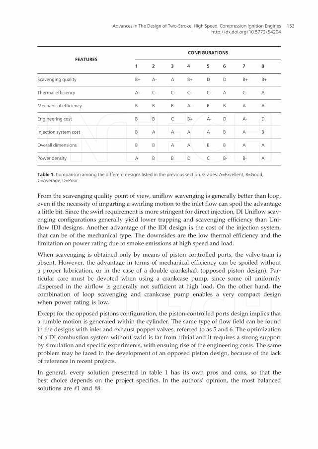
FEATURESCONFIGURATIONS
1 2 3 4 5 6 7 8
Scavenging quality B+ A- A B+ D D B+ B+
Thermal efficiency A- C- C- C- C- A C- A
Mechanical efficiency B B B A- B B A A
Engineering cost B B C B+ A- D A- D
Injection system cost B A A A A B A B
Overall dimensions B B A A B B A A
Power density A B B D C B- B- A
Table 1. Comparison among the different designs listed in the previous section. Grades: A=Excellent, B=Good,C=Average, D=Poor
From the scavenging quality point of view, uniflow scavenging is generally better than loop,even if the necessity of imparting a swirling motion to the inlet flow can spoil the advantagea little bit. Since the swirl requirement is more stringent for direct injection, DI Uniflow scav‐enging configurations generally yield lower trapping and scavenging efficiency than Uni‐flow IDI designs. Another advantage of the IDI design is the cost of the injection system,that can be of the mechanical type. The downsides are the low thermal efficiency and thelimitation on power rating due to smoke emissions at high speed and load.
When scavenging is obtained only by means of piston controlled ports, the valve-train isabsent. However, the advantage in terms of mechanical efficiency can be spoiled withouta proper lubrication, or in the case of a double crankshaft (opposed piston design). Par‐ticular care must be devoted when using a crankcase pump, since some oil uniformlydispersed in the airflow is generally not sufficient at high load. On the other hand, thecombination of loop scavenging and crankcase pump enables a very compact designwhen power rating is low.
Except for the opposed pistons configuration, the piston-controlled ports design implies thata tumble motion is generated within the cylinder. The same type of flow field can be foundin the designs with inlet and exhaust poppet valves, referred to as 5 and 6. The optimizationof a DI combustion system without swirl is far from trivial and it requires a strong supportby simulation and specific experiments, with ensuing rise of the engineering costs. The sameproblem may be faced in the development of an opposed piston design, because of the lackof reference in recent projects.
In general, every solution presented in table 1 has its own pros and cons, so that thebest choice depends on the project specifics. In the authors’ opinion, the most balancedsolutions are #1 and #8.
Advances in The Design of Two-Stroke, High Speed, Compression Ignition Engineshttp://dx.doi.org/10.5772/54204
153
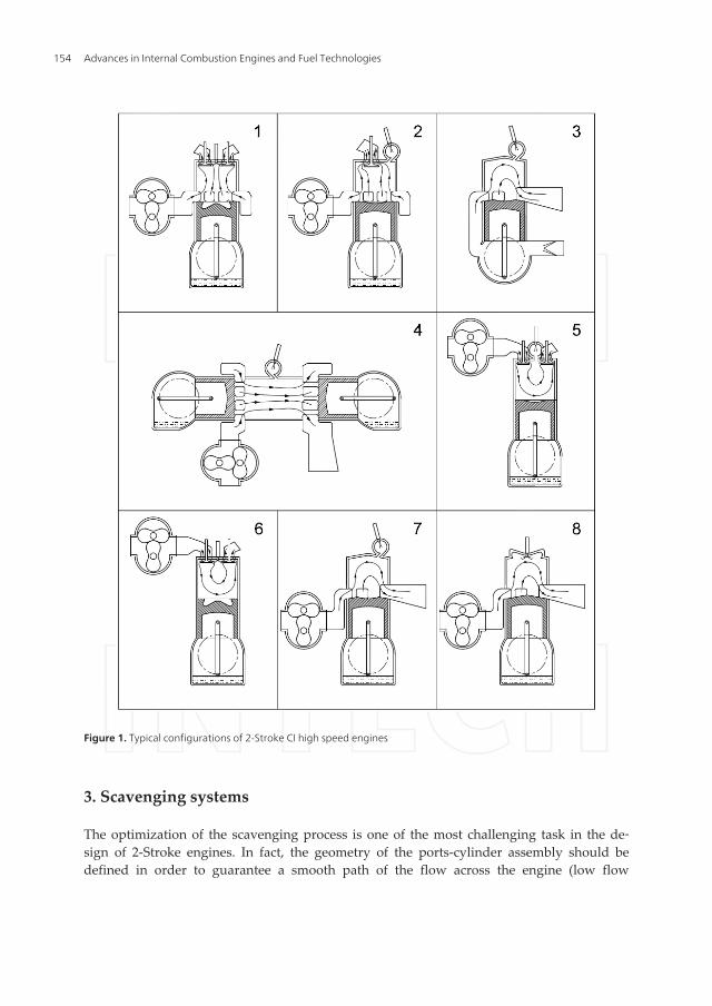
Figure 1. Typical configurations of 2-Stroke CI high speed engines
3. Scavenging systems
The optimization of the scavenging process is one of the most challenging task in the de‐sign of 2-Stroke engines. In fact, the geometry of the ports-cylinder assembly should bedefined in order to guarantee a smooth path of the flow across the engine (low flow
Advances in Internal Combustion Engines and Fuel Technologies154
losses), while minimizing short circuiting and the mixing between fresh charge and ex‐haust gas. Another important issue is the conditioning of the mean in- cylinder flowfield (swirl or tumble), which strongly affects both combustion and heat transfer. The op‐timum intensity of the swirl/tumble rates depends on the type of combustion system, aswell as on the specific project targets. As an example, the swirl ratio in DI engine with abowl in the piston should be high enough to promote the diffusion of the fuel vapor inthe chamber. However, an excessive mean turbulence is detrimental to spray penetration,and heat losses increase.
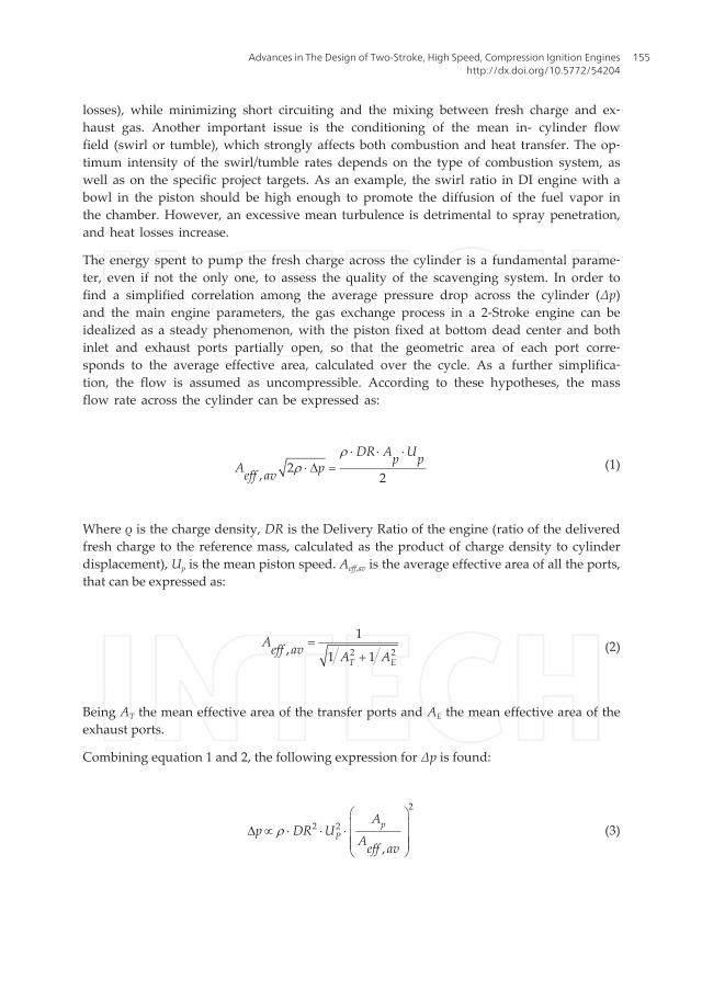
The energy spent to pump the fresh charge across the cylinder is a fundamental parame‐ter, even if not the only one, to assess the quality of the scavenging system. In order tofind a simplified correlation among the average pressure drop across the cylinder (Δp)and the main engine parameters, the gas exchange process in a 2-Stroke engine can beidealized as a steady phenomenon, with the piston fixed at bottom dead center and bothinlet and exhaust ports partially open, so that the geometric area of each port corre‐sponds to the average effective area, calculated over the cycle. As a further simplifica‐tion, the flow is assumed as uncompressible. According to these hypotheses, the massflow rate across the cylinder can be expressed as:
2, 2
DR A Up pA peff av
rr
× × ×× D = (1)
Where ρ is the charge density, DR is the Delivery Ratio of the engine (ratio of the deliveredfresh charge to the reference mass, calculated as the product of charge density to cylinderdisplacement), Up is the mean piston speed. Aeff,av is the average effective area of all the ports,that can be expressed as:
2 2
1, 1 1T E
Aeff av A A=
+(2)
Being AT the mean effective area of the transfer ports and AE the mean effective area of theexhaust ports.
Combining equation 1 and 2, the following expression for Δp is found:
2
2 2
,
pP
Ap DR U
Aeff avr
æ öç ÷D µ × × × ç ÷ç ÷è ø
(3)
Advances in The Design of Two-Stroke, High Speed, Compression Ignition Engineshttp://dx.doi.org/10.5772/54204
155
The following observations can be made:
1. Equation (3), despite the simplifications, is able to yield qualitative information aboutthe engine permeability, i.e. the attitude of the ports system to throttle the flow acrossthe cylinder.
2. The higher is the delivery ratio and the maximum mean piston speed, the more impor‐tant is to have high values of effective area, in comparison to the piston area. Also thecharge density plays a role, thus supercharged engines are more demanding in terms ofpermeability than naturally aspirated units.
3. The ports average effective area can be increased by reducing the flow losses and/or byincreasing the opening area of both inlet and exhaust ports.
While permeability is related to the mean piston speed, Diesel combustion is affected by en‐gine speed: the lower is the maximum number of revolutions per minute, the less is the needof turbulence to support air-fuel mixing.
A number of different lay-outs has been proposed in more than one century of history, andit would be quite hard to review all of them. The two most widespread designs, at least forhigh speed engines, are the Loop and the Uniflow configurations, the former with pistoncontrolled ports, the latter with exhaust poppet valves, driven by a camshaft, and pistoncontrolled inlet ports. Uniflow scavenging with opposed pistons is not considered, for thesake of brevity.
CFD simulation is the key for the design of modern scavenging systems. The numericalanalyses are carried out by means of 3D tools, which are able to predict the flow fielddetails within the cylinder and through the ports under actual engine operating condi‐tions. Because of the computational cost, the simulation domain is limited to a single cyl‐inder, and to the portion of cycle included between exhaust port opening and exhaustport closing. Therefore, initial and boundary conditions must be provided by anothertype of CFD tool, able to analyze the full engine cycle and the influence of the whole en‐gine lay-out, even if in a simplified manner (in particular, the spatial distribution of theflow through the intake and exhaust systems is considered as one or zero dimensional).The authors have applied this methodology in a number of studies [8, 12-14, 20-25], com‐paring the simulation results to the experiments, whenever possible. CFD simulation wasfound to be a quite reliable tool, provided that the numerical models are always under‐pinned by some experimental evidence.
4. Loop scavenging
For loop scavenged engines, a quite successful design, applicable to both crankcase andexternal scavenging, is shown in figure 2 (left). As visible, there is a symmetry planepassing through the twin exhaust ports (E1, E2) and the rear transfer port (T5). Thetransfer ports 1-4 blow the fresh charge toward the wall opposite to the exhaust side,
Advances in Internal Combustion Engines and Fuel Technologies156
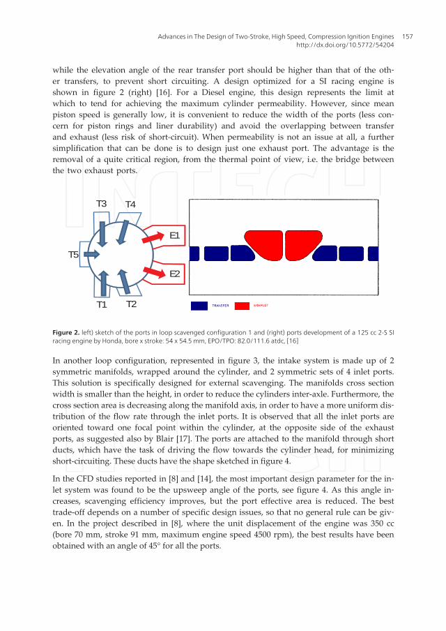
while the elevation angle of the rear transfer port should be higher than that of the oth‐er transfers, to prevent short circuiting. A design optimized for a SI racing engine isshown in figure 2 (right) [16]. For a Diesel engine, this design represents the limit atwhich to tend for achieving the maximum cylinder permeability. However, since meanpiston speed is generally low, it is convenient to reduce the width of the ports (less con‐cern for piston rings and liner durability) and avoid the overlapping between transferand exhaust (less risk of short-circuit). When permeability is not an issue at all, a furthersimplification that can be done is to design just one exhaust port. The advantage is theremoval of a quite critical region, from the thermal point of view, i.e. the bridge betweenthe two exhaust ports.
T5
T1 T2
T3 T4
E1
E2
Figure 2. left) sketch of the ports in loop scavenged configuration 1 and (right) ports development of a 125 cc 2-S SIracing engine by Honda, bore x stroke: 54 x 54.5 mm, EPO/TPO: 82.0/111.6 atdc, [16]
In another loop configuration, represented in figure 3, the intake system is made up of 2symmetric manifolds, wrapped around the cylinder, and 2 symmetric sets of 4 inlet ports.This solution is specifically designed for external scavenging. The manifolds cross sectionwidth is smaller than the height, in order to reduce the cylinders inter-axle. Furthermore, thecross section area is decreasing along the manifold axis, in order to have a more uniform dis‐tribution of the flow rate through the inlet ports. It is observed that all the inlet ports areoriented toward one focal point within the cylinder, at the opposite side of the exhaustports, as suggested also by Blair [17]. The ports are attached to the manifold through shortducts, which have the task of driving the flow towards the cylinder head, for minimizingshort-circuiting. These ducts have the shape sketched in figure 4.
In the CFD studies reported in [8] and [14], the most important design parameter for the in‐let system was found to be the upsweep angle of the ports, see figure 4. As this angle in‐creases, scavenging efficiency improves, but the port effective area is reduced. The besttrade-off depends on a number of specific design issues, so that no general rule can be giv‐en. In the project described in [8], where the unit displacement of the engine was 350 cc(bore 70 mm, stroke 91 mm, maximum engine speed 4500 rpm), the best results have beenobtained with an angle of 45° for all the ports.
Advances in The Design of Two-Stroke, High Speed, Compression Ignition Engineshttp://dx.doi.org/10.5772/54204
157
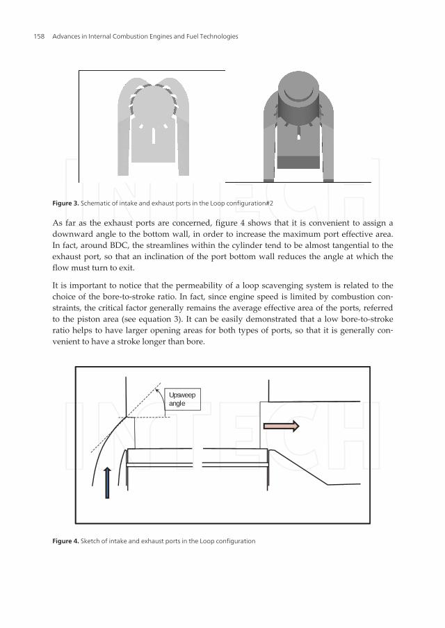
Figure 3. Schematic of intake and exhaust ports in the Loop configuration#2
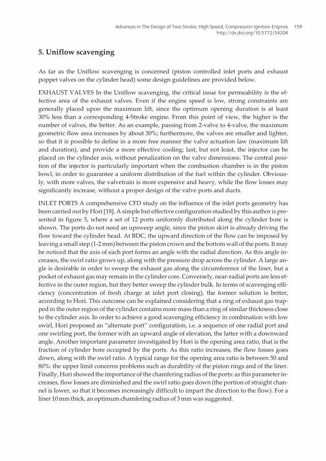
As far as the exhaust ports are concerned, figure 4 shows that it is convenient to assign adownward angle to the bottom wall, in order to increase the maximum port effective area.In fact, around BDC, the streamlines within the cylinder tend to be almost tangential to theexhaust port, so that an inclination of the port bottom wall reduces the angle at which theflow must turn to exit.
It is important to notice that the permeability of a loop scavenging system is related to thechoice of the bore-to-stroke ratio. In fact, since engine speed is limited by combustion con‐straints, the critical factor generally remains the average effective area of the ports, referredto the piston area (see equation 3). It can be easily demonstrated that a low bore-to-strokeratio helps to have larger opening areas for both types of ports, so that it is generally con‐venient to have a stroke longer than bore.
Upsweepangle
Figure 4. Sketch of intake and exhaust ports in the Loop configuration
Advances in Internal Combustion Engines and Fuel Technologies158
5. Uniflow scavenging
As far as the Uniflow scavenging is concerned (piston controlled inlet ports and exhaustpoppet valves on the cylinder head) some design guidelines are provided below.
EXHAUST VALVES In the Uniflow scavenging, the critical issue for permeability is the ef‐fective area of the exhaust valves. Even if the engine speed is low, strong constraints aregenerally placed upon the maximum lift, since the optimum opening duration is at least30% less than a corresponding 4-Stroke engine. From this point of view, the higher is thenumber of valves, the better. As an example, passing from 2-valve to 4-valve, the maximumgeometric flow area increases by about 30%; furthermore, the valves are smaller and lighter,so that it is possible to define in a more free manner the valve actuation law (maximum liftand duration), and provide a more effective cooling; last, but not least, the injector can beplaced on the cylinder axis, without penalization on the valve dimensions. The central posi‐tion of the injector is particularly important when the combustion chamber is in the pistonbowl, in order to guarantee a uniform distribution of the fuel within the cylinder. Obvious‐ly, with more valves, the valvetrain is more expensive and heavy, while the flow losses maysignificantly increase, without a proper design of the valve ports and ducts.
INLET PORTS A comprehensive CFD study on the influence of the inlet ports geometry hasbeen carried out by Hori [18]. A simple but effective configuration studied by this author is pre‐sented in figure 5, where a set of 12 ports uniformly distributed along the cylinder bore isshown. The ports do not need an upsweep angle, since the piston skirt is already driving theflow toward the cylinder head. At BDC, the upward direction of the flow can be imposed byleaving a small step (1-2 mm) between the piston crown and the bottom wall of the ports. It maybe noticed that the axis of each port forms an angle with the radial direction. As this angle in‐creases, the swirl ratio grows up, along with the pressure drop across the cylinder. A large an‐gle is desirable in order to sweep the exhaust gas along the circumference of the liner, but apocket of exhaust gas may remain in the cylinder core. Conversely, near-radial ports are less ef‐fective in the outer region, but they better sweep the cylinder bulk. In terms of scavenging effi‐ciency (concentration of fresh charge at inlet port closing), the former solution is better,according to Hori. This outcome can be explained considering that a ring of exhaust gas trap‐ped in the outer region of the cylinder contains more mass than a ring of similar thickness closeto the cylinder axis. In order to achieve a good scavenging efficiency in combination with lowswirl, Hori proposed an “alternate port” configuration, i.e. a sequence of one radial port andone swirling port, the former with an upward angle of elevation, the latter with a downwardangle. Another important parameter investigated by Hori is the opening area ratio, that is thefraction of cylinder bore occupied by the ports. As this ratio increases, the flow losses goesdown, along with the swirl ratio. A typical range for the opening area ratio is between 50 and80%: the upper limit concerns problems such as durability of the piston rings and of the liner.Finally, Hori showed the importance of the chamfering radius of the ports: as this parameter in‐creases, flow losses are diminished and the swirl ratio goes down (the portion of straight chan‐nel is lower, so that it becomes increasingly difficult to impart the direction to the flow). For aliner 10 mm thick, an optimum chamfering radius of 3 mm was suggested.
Advances in The Design of Two-Stroke, High Speed, Compression Ignition Engineshttp://dx.doi.org/10.5772/54204
159
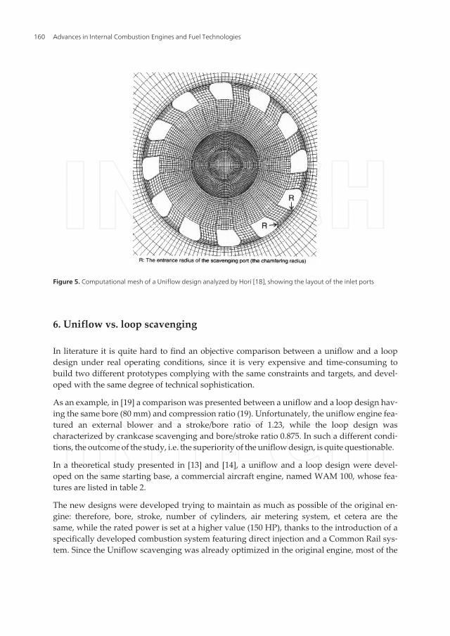
Figure 5. Computational mesh of a Uniflow design analyzed by Hori [18], showing the layout of the inlet ports
6. Uniflow vs. loop scavenging
In literature it is quite hard to find an objective comparison between a uniflow and a loopdesign under real operating conditions, since it is very expensive and time-consuming tobuild two different prototypes complying with the same constraints and targets, and devel‐oped with the same degree of technical sophistication.
As an example, in [19] a comparison was presented between a uniflow and a loop design hav‐ing the same bore (80 mm) and compression ratio (19). Unfortunately, the uniflow engine fea‐tured an external blower and a stroke/bore ratio of 1.23, while the loop design wascharacterized by crankcase scavenging and bore/stroke ratio 0.875. In such a different condi‐tions, the outcome of the study, i.e. the superiority of the uniflow design, is quite questionable.
In a theoretical study presented in [13] and [14], a uniflow and a loop design were devel‐oped on the same starting base, a commercial aircraft engine, named WAM 100, whose fea‐tures are listed in table 2.
The new designs were developed trying to maintain as much as possible of the original en‐gine: therefore, bore, stroke, number of cylinders, air metering system, et cetera are thesame, while the rated power is set at a higher value (150 HP), thanks to the introduction of aspecifically developed combustion system featuring direct injection and a Common Rail sys‐tem. Since the Uniflow scavenging was already optimized in the original engine, most of the
Advances in Internal Combustion Engines and Fuel Technologies160
attention was paid to the loop version. Here, a ports design as the one visible in figure 3 wasadopted, and optimized via CFD-3D simulations.
Engine type 2-Stroke, 3-cylinder in-line
Combustion Diesel, Indirect Injection
Scavenging type Uniflow
Number of Valves/Ports 2 Exh. valves/20 inlet ports
Air Metering Turbocharger + Roots blower
Fuel Metering In-line mechanical pump
Injector nozzle type Single-hole (Pintle)
Displaced volume 1832 cc
Stroke 95.0 mm
Bore 90.5 mm
Connecting Rod 167.0 mm
Compression ratio 17:1
Exhaust Valves Open 83° before BDC
Exhaust Valves Close 80° after BDC
Inlet Port Open 53° before BDC
Inlet Port Close 53° after BDC
Maximum Brake Power 102 HP @ 2750 rpm
Table 2. Main features of the WAM 100 engine, assumed as a starting base for the CFD study presented in [13] and [14].
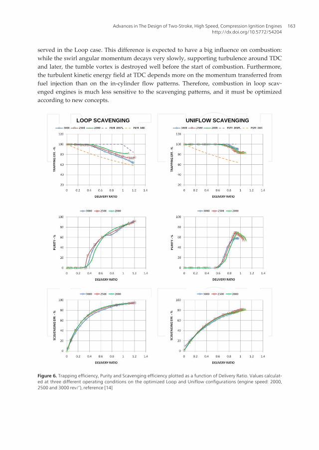
A comparison between the scavenging parameters calculated under real engine operatingconditions (2000, 2500 and 3000 rpm, full load) is presented in figure 6. Figure 7 presents apictorial view of the fresh charge concentration on a plane passing through the cylinder axis,at different crank angle. Engine speed is 2500 rpm, full load.
The scavenging parameters are defined as follows. The Trapping Efficiency (TE) is the ratioof the mass of fresh air retained within the cylinder to the mass of fresh air delivered; theScavenging Efficiency (SE) is the ratio of the mass of fresh charge retained to the total cylin‐der mass (fresh+exhaust); the Exhaust Gas Purity is the mass fraction of fresh charge in theexhaust flow leaving the cylinder; finally, the reference mass is calculated considering theaverage delivery density and the total displaced volume.
Analyzing figures 6 and 7, it is observed that operating conditions affect Uniflow scaveng‐ing very slightly, while the influence is more evident on Loop. It should be considered thatthese conditions are defined not only by speed, but also by the pressure traces forced at boththe inlet and the outlet boundaries, which are obviously different from case to case for rep‐resenting real engine operations. The lower data scattering of the Uniflow design may bemainly explained by the more regular pressure traces.
Advances in The Design of Two-Stroke, High Speed, Compression Ignition Engineshttp://dx.doi.org/10.5772/54204
161
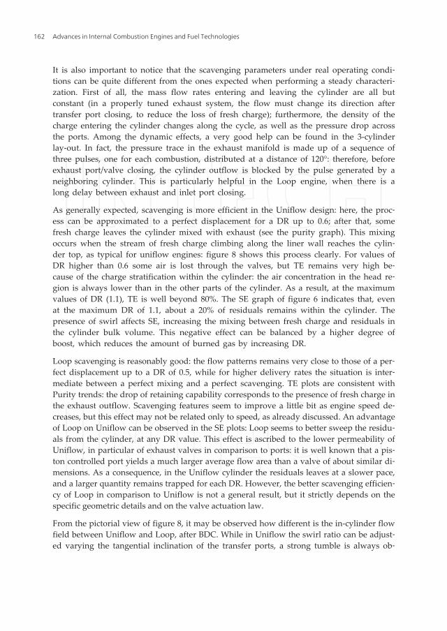
It is also important to notice that the scavenging parameters under real operating condi‐tions can be quite different from the ones expected when performing a steady characteri‐zation. First of all, the mass flow rates entering and leaving the cylinder are all butconstant (in a properly tuned exhaust system, the flow must change its direction aftertransfer port closing, to reduce the loss of fresh charge); furthermore, the density of thecharge entering the cylinder changes along the cycle, as well as the pressure drop acrossthe ports. Among the dynamic effects, a very good help can be found in the 3-cylinderlay-out. In fact, the pressure trace in the exhaust manifold is made up of a sequence ofthree pulses, one for each combustion, distributed at a distance of 120°: therefore, beforeexhaust port/valve closing, the cylinder outflow is blocked by the pulse generated by aneighboring cylinder. This is particularly helpful in the Loop engine, when there is along delay between exhaust and inlet port closing.
As generally expected, scavenging is more efficient in the Uniflow design: here, the proc‐ess can be approximated to a perfect displacement for a DR up to 0.6; after that, somefresh charge leaves the cylinder mixed with exhaust (see the purity graph). This mixingoccurs when the stream of fresh charge climbing along the liner wall reaches the cylin‐der top, as typical for uniflow engines: figure 8 shows this process clearly. For values ofDR higher than 0.6 some air is lost through the valves, but TE remains very high be‐cause of the charge stratification within the cylinder: the air concentration in the head re‐gion is always lower than in the other parts of the cylinder. As a result, at the maximumvalues of DR (1.1), TE is well beyond 80%. The SE graph of figure 6 indicates that, evenat the maximum DR of 1.1, about a 20% of residuals remains within the cylinder. Thepresence of swirl affects SE, increasing the mixing between fresh charge and residuals inthe cylinder bulk volume. This negative effect can be balanced by a higher degree ofboost, which reduces the amount of burned gas by increasing DR.
Loop scavenging is reasonably good: the flow patterns remains very close to those of a per‐fect displacement up to a DR of 0.5, while for higher delivery rates the situation is inter‐mediate between a perfect mixing and a perfect scavenging. TE plots are consistent withPurity trends: the drop of retaining capability corresponds to the presence of fresh charge inthe exhaust outflow. Scavenging features seem to improve a little bit as engine speed de‐creases, but this effect may not be related only to speed, as already discussed. An advantageof Loop on Uniflow can be observed in the SE plots: Loop seems to better sweep the residu‐als from the cylinder, at any DR value. This effect is ascribed to the lower permeability ofUniflow, in particular of exhaust valves in comparison to ports: it is well known that a pis‐ton controlled port yields a much larger average flow area than a valve of about similar di‐mensions. As a consequence, in the Uniflow cylinder the residuals leaves at a slower pace,and a larger quantity remains trapped for each DR. However, the better scavenging efficien‐cy of Loop in comparison to Uniflow is not a general result, but it strictly depends on thespecific geometric details and on the valve actuation law.
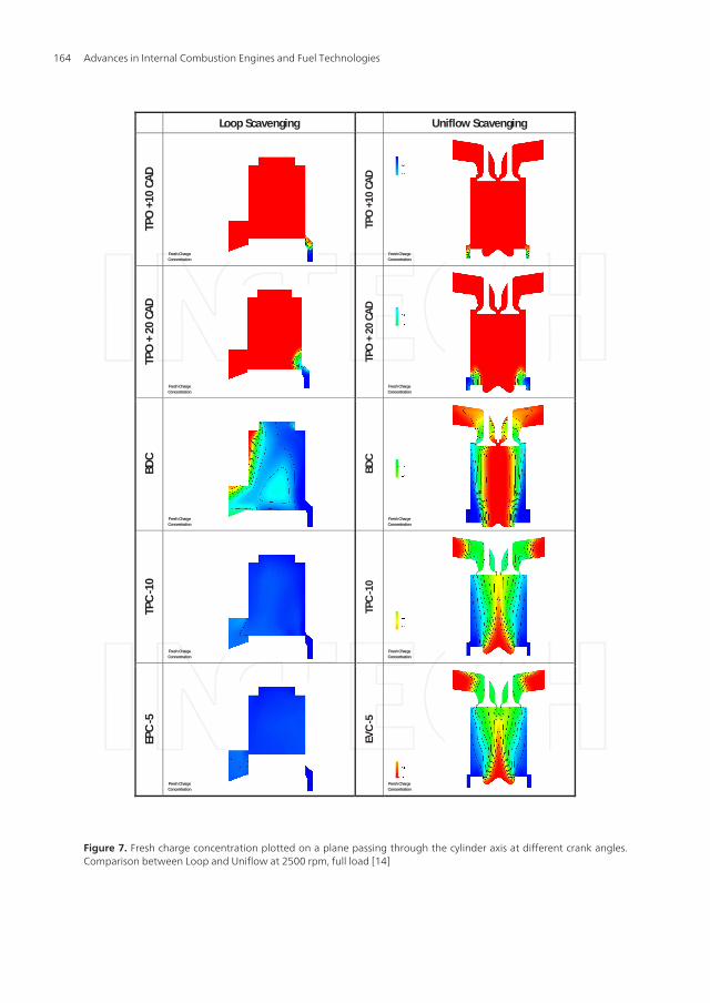
From the pictorial view of figure 8, it may be observed how different is the in-cylinder flowfield between Uniflow and Loop, after BDC. While in Uniflow the swirl ratio can be adjust‐ed varying the tangential inclination of the transfer ports, a strong tumble is always ob‐
Advances in Internal Combustion Engines and Fuel Technologies162
served in the Loop case. This difference is expected to have a big influence on combustion:while the swirl angular momentum decays very slowly, supporting turbulence around TDCand later, the tumble vortex is destroyed well before the start of combustion. Furthermore,the turbulent kinetic energy field at TDC depends more on the momentum transferred fromfuel injection than on the in-cylinder flow patterns. Therefore, combustion in loop scav‐enged engines is much less sensitive to the scavenging patterns, and it must be optimizedaccording to new concepts.
LOOP SCAVENGING UNIFLOW SCAVENGING
Figure 6: Trapping efficiency, Purity and Scavenging efficiency plotted as a function of Delivery Ratio. Values calculated at three different operating conditions on the optimized
Loop and Uniflow configurations (engine speed: 2000, 2500 and 3000 rev/’), reference [14]
Figure 6. Trapping efficiency, Purity and Scavenging efficiency plotted as a function of Delivery Ratio. Values calculat‐ed at three different operating conditions on the optimized Loop and Uniflow configurations (engine speed: 2000,2500 and 3000 rev/’), reference [14]
Advances in The Design of Two-Stroke, High Speed, Compression Ignition Engineshttp://dx.doi.org/10.5772/54204
163
Loop Scavenging Uniflow Scavenging
TPO
+10
CA
D
TPO
+10
CA
D
TPO
+ 2
0 CA
D
TPO
+ 2
0 CA
D
BDC
BDC
TPC
-10
TPC
-10
EPC
-5
EVC
-5
Fresh Charge Concentration
Fresh Charge Concentration
Fresh Charge Concentration
Fresh Charge Concentration
Fresh Charge Concentration
Fresh Charge Concentration
Fresh Charge Concentration
Fresh Charge Concentration
Fresh Charge Concentration
Fresh Charge Concentration
Figure 7. Fresh charge concentration plotted on a plane passing through the cylinder axis at different crank angles.Comparison between Loop and Uniflow at 2500 rpm, full load [14]
Advances in Internal Combustion Engines and Fuel Technologies164
Loop Scavenging Uniflow Scavenging TP
O +
10 C
AD
TPO
+10
CA
D
TPO
+ 2
0 CA
D
TPO
+ 2
0 CA
D
BDC
BDC
TPC
-10
TPC
-10
EPC
-5
EVC
-5
Velocity [cm/s]
Velocity [cm/s]
Velocity [cm/s]
Velocity [cm/s]
Velocity [cm/s]
Velocity [cm/s]
Velocity [cm/s]
Velocity [cm/s]
Velocity [cm/s]
Velocity [cm/s]
Figure 8. Velocity vectors plotted on a plane passing through the cylinder axis at different crank angles. Comparisonbetween Loop and Uniflow designs at 2500 rpm, full load [14]
Advances in The Design of Two-Stroke, High Speed, Compression Ignition Engineshttp://dx.doi.org/10.5772/54204
165
7. Combustion system design
As anticipated in the previous sections, the most difficult challenge when designing thecombustion system of a 2-Stroke Diesel engine is to achieve an efficient combustion withoutswirl. This situation always occurs in loop scavenging, while, for the uniflow design dis‐cussed in the previous section, it is possible to import a combustion system directly from a4-stroke project. Since a comprehensive literature already exists on the optimization of bowlin the piston chambers, this subject won’t be considered, and all the attention is going to befocused on the loop scavenged engines. The lack of knowledge on this type of combustionsystems for high speed Diesel engines requires an extensive work in order to optimize thewide range of design parameters.
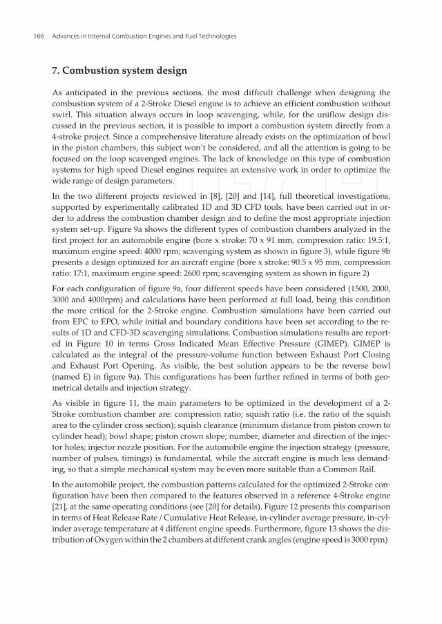
In the two different projects reviewed in [8], [20] and [14], full theoretical investigations,supported by experimentally calibrated 1D and 3D CFD tools, have been carried out in or‐der to address the combustion chamber design and to define the most appropriate injectionsystem set-up. Figure 9a shows the different types of combustion chambers analyzed in thefirst project for an automobile engine (bore x stroke: 70 x 91 mm, compression ratio: 19.5:1,maximum engine speed: 4000 rpm; scavenging system as shown in figure 3), while figure 9bpresents a design optimized for an aircraft engine (bore x stroke: 90.5 x 95 mm, compressionratio: 17:1, maximum engine speed: 2600 rpm; scavenging system as shown in figure 2)
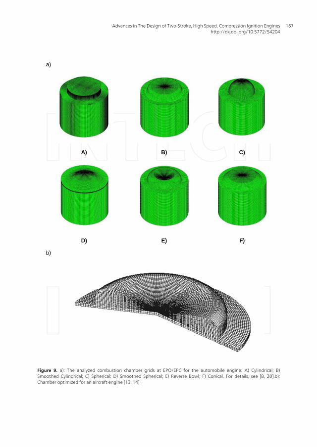
For each configuration of figure 9a, four different speeds have been considered (1500, 2000,3000 and 4000rpm) and calculations have been performed at full load, being this conditionthe more critical for the 2-Stroke engine. Combustion simulations have been carried outfrom EPC to EPO, while initial and boundary conditions have been set according to the re‐sults of 1D and CFD-3D scavenging simulations. Combustion simulations results are report‐ed in Figure 10 in terms Gross Indicated Mean Effective Pressure (GIMEP). GIMEP iscalculated as the integral of the pressure-volume function between Exhaust Port Closingand Exhaust Port Opening. As visible, the best solution appears to be the reverse bowl(named E) in figure 9a). This configurations has been further refined in terms of both geo‐metrical details and injection strategy.
As visible in figure 11, the main parameters to be optimized in the development of a 2-Stroke combustion chamber are: compression ratio; squish ratio (i.e. the ratio of the squisharea to the cylinder cross section); squish clearance (minimum distance from piston crown tocylinder head); bowl shape; piston crown slope; number, diameter and direction of the injec‐tor holes; injector nozzle position. For the automobile engine the injection strategy (pressure,number of pulses, timings) is fundamental, while the aircraft engine is much less demand‐ing, so that a simple mechanical system may be even more suitable than a Common Rail.
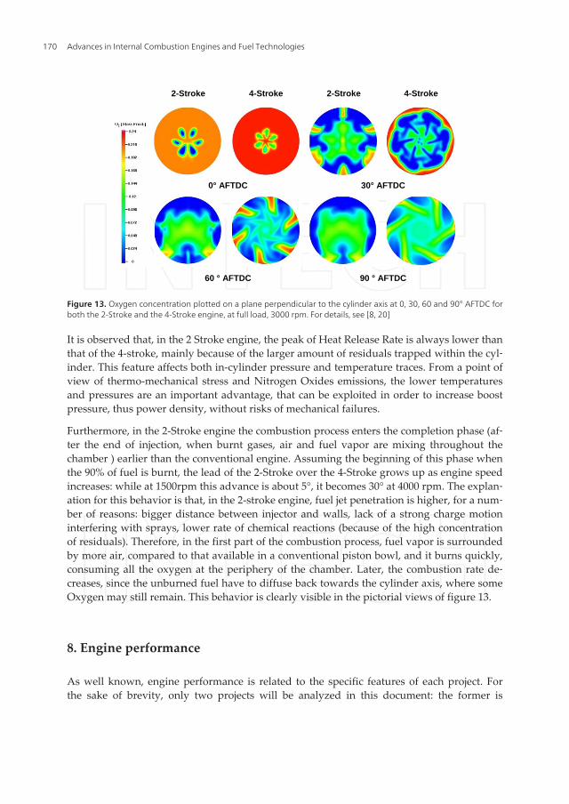
In the automobile project, the combustion patterns calculated for the optimized 2-Stroke con‐figuration have been then compared to the features observed in a reference 4-Stroke engine[21], at the same operating conditions (see [20] for details). Figure 12 presents this comparisonin terms of Heat Release Rate / Cumulative Heat Release, in-cylinder average pressure, in-cyl‐inder average temperature at 4 different engine speeds. Furthermore, figure 13 shows the dis‐tribution of Oxygen within the 2 chambers at different crank angles (engine speed is 3000 rpm)
Advances in Internal Combustion Engines and Fuel Technologies166
a)
A) B) C)
D) E) F)
b)
Figure 9. a): The analyzed combustion chamber grids at EPO/EPC for the automobile engine: A) Cylindrical; B)Smoothed Cylindrical; C) Spherical; D) Smoothed Spherical; E) Reverse Bowl; F) Conical. For details, see [8, 20].b):Chamber optimized for an aircraft engine [13, 14]
Advances in The Design of Two-Stroke, High Speed, Compression Ignition Engineshttp://dx.doi.org/10.5772/54204
167
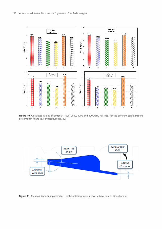
Figure 10. Calculated values of GIMEP at 1500, 2000, 3000 and 4000rpm, full load, for the different configurationspresented in figure 9a. For details, see [8, 20]
Figure 11. The most important parameters for the optimization of a reverse bowl combustion chamber
Advances in Internal Combustion Engines and Fuel Technologies168
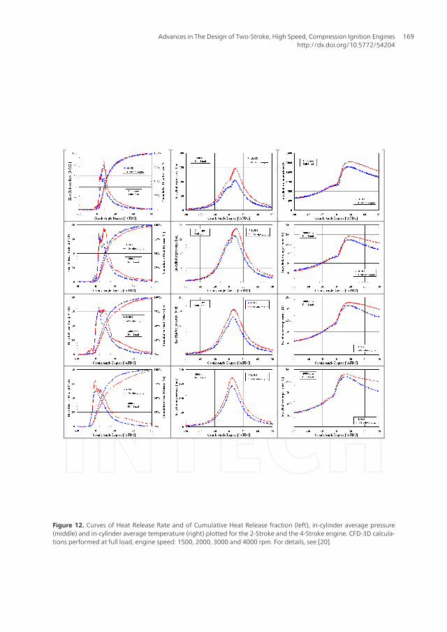
Figure 12. Curves of Heat Release Rate and of Cumulative Heat Release fraction (left), in-cylinder average pressure(middle) and in-cylinder average temperature (right) plotted for the 2-Stroke and the 4-Stroke engine. CFD-3D calcula‐tions performed at full load, engine speed: 1500, 2000, 3000 and 4000 rpm. For details, see [20].
Advances in The Design of Two-Stroke, High Speed, Compression Ignition Engineshttp://dx.doi.org/10.5772/54204
169
2-Stroke 4-Stroke 2-Stroke 4-Stroke
0° AFTDC 30° AFTDC
60 ° AFTDC 90 ° AFTDC
Figure 13: Oxygen concentration plotted on a plane perpendicular to the cylinder axis at 0, 30, 60 and 90° AFTDC for both the 2-Stroke and the 4-Stroke engine, at full load, 3000 rpm.
For details, see [8, 20]
ENGINE PERFORMANCE
As well known, engine performance is related to the specific features of each project. For the sake of brevity, only two projects will be analyzed in this document: the former is the 1.05L automobile engine developed by the University of Modena and Reggio Emilia and described in [8], the latter is the aircraft engine of table 2, in both uniflow and loop versions [21, 22].
The automobile 2-S engine is a 3-cylinder, DI loop scavenged unit, having a total capacity of 1050 cc, bore x stroke: 70x91 mm, compression ratio: 19.5:1, supercharged and intercooled. The supercharging system is made up of a turbocharger, with variable geometry turbine, and a Roots blower, serially connected. The intercooler is between the two compression stages. Different versions of the engine have been developed, but only one will be considered here, for the sake of brevity. This version, named BASE, includes a valve, able to modify the opening/closing timing of the exhaust port. The 2-S automobile engine is compared to a reference 4-Stroke commercial unit, whose features are: 4-cylinder in line, direct injection with a Common Rail system; 4-valve; total displacement: 1251 cc; bore x stroke: 69.6x 82 mm; compression ratio: 17.6; turbocharged with a variable geometry turbine and intercooled; max. power 67 kW@4000 rpm; cooled EGR system, EURO IV compliant.
Since no prototype of the 2-S engine has been built at the moment, the comparison with 4-S is performed by means of CFD simulations, carried out at the same conditions and with
Figure 13. Oxygen concentration plotted on a plane perpendicular to the cylinder axis at 0, 30, 60 and 90° AFTDC forboth the 2-Stroke and the 4-Stroke engine, at full load, 3000 rpm. For details, see [8, 20]
It is observed that, in the 2 Stroke engine, the peak of Heat Release Rate is always lower thanthat of the 4-stroke, mainly because of the larger amount of residuals trapped within the cyl‐inder. This feature affects both in-cylinder pressure and temperature traces. From a point ofview of thermo-mechanical stress and Nitrogen Oxides emissions, the lower temperaturesand pressures are an important advantage, that can be exploited in order to increase boostpressure, thus power density, without risks of mechanical failures.
Furthermore, in the 2-Stroke engine the combustion process enters the completion phase (af‐ter the end of injection, when burnt gases, air and fuel vapor are mixing throughout thechamber ) earlier than the conventional engine. Assuming the beginning of this phase whenthe 90% of fuel is burnt, the lead of the 2-Stroke over the 4-Stroke grows up as engine speedincreases: while at 1500rpm this advance is about 5°, it becomes 30° at 4000 rpm. The explan‐ation for this behavior is that, in the 2-stroke engine, fuel jet penetration is higher, for a num‐ber of reasons: bigger distance between injector and walls, lack of a strong charge motioninterfering with sprays, lower rate of chemical reactions (because of the high concentrationof residuals). Therefore, in the first part of the combustion process, fuel vapor is surroundedby more air, compared to that available in a conventional piston bowl, and it burns quickly,consuming all the oxygen at the periphery of the chamber. Later, the combustion rate de‐creases, since the unburned fuel have to diffuse back towards the cylinder axis, where someOxygen may still remain. This behavior is clearly visible in the pictorial views of figure 13.
8. Engine performance
As well known, engine performance is related to the specific features of each project. Forthe sake of brevity, only two projects will be analyzed in this document: the former is
Advances in Internal Combustion Engines and Fuel Technologies170
the 1.05L automobile engine developed by the University of Modena and Reggio Emiliaand described in [8], the latter is the aircraft engine of table 2, in both uniflow and loopversions [21, 22].
The automobile 2-S engine is a 3-cylinder, DI loop scavenged unit, having a total capacity of1050 cc, bore x stroke: 70x91 mm, compression ratio: 19.5:1, supercharged and intercooled.The supercharging system is made up of a turbocharger, with variable geometry turbine,and a Roots blower, serially connected. The intercooler is between the two compressionstages. Different versions of the engine have been developed, but only one will be consid‐ered here, for the sake of brevity. This version, named BASE, includes a valve, able to modi‐fy the opening/closing timing of the exhaust port. The 2-S automobile engine is compared toa reference 4-Stroke commercial unit, whose features are: 4-cylinder in line, direct injectionwith a Common Rail system; 4-valve; total displacement: 1251 cc; bore x stroke: 69.6x 82mm; compression ratio: 17.6; turbocharged with a variable geometry turbine and inter‐cooled; max. power 67 kW@4000 rpm; cooled EGR system, EURO IV compliant.
Since no prototype of the 2-S engine has been built at the moment, the comparison with 4-Sis performed by means of CFD simulations, carried out at the same conditions and withmodels as similar as possible. In particular, at full load the injection rates are set in order tohave the same value of trapped air-fuel ratio..
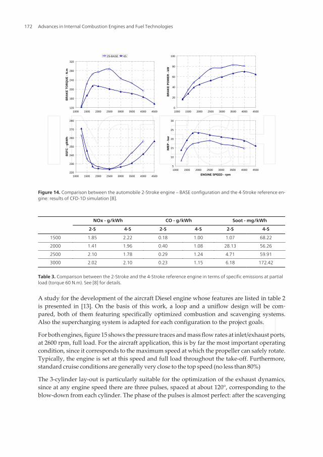
First, the comparison is made in terms brake torque, power and fuel specific consumptionobtained at constant speed and full load. A graph of IMEP is added too, because of the im‐portance of this parameter as an index of the engine thermo-mechanical stress. Such a com‐parison is shown in figure 14.
Figure 14 clearly demonstrates the superiority of the 2-Stroke engine under every point ofview, except fuel economy. However, it should be considered that friction losses of the 2-stroke unit are probably over-estimated. A definitive confrontation, under this point ofview, will be possible only when a 2-Stroke prototype will be physically built and tested.
For a passenger car engine, emissions at partial load are paramount. Therefore, a compari‐son between the 2-S and the 4-S engine is carried out at low load, corresponding to a braketorque of 60 N.m. The calculations are performed using a 3-D CFD tool (KIVA-3V) in combi‐nation with the usual GT-Power analysis.
As visible in table 3, Soot and Carbon Monoxide emissions are strongly reduced in the 2-Stroke engine (-89% and -75%, respectively), while the reduction of Nitrogen Oxides is lesssignificant. However, it is reminded that the 2-Stroke engine does not need any EGR deviceto keep the NOx under control. These outcomes can be easily explained considering that thetorque target in the 2-S engine is achieved at a much higher air-fuel ratio, because of thedouble cycle frequency and the presence of the Roots blower keeping the turbochargerspeed higher. The air excess makes oxidation processes much more complete, while temper‐ature remains low, without need of external EGR. The last issue has a positive influence alsoon brake specific fuel consumption, since the external EGR system introduces additionalpumping losses.
Advances in The Design of Two-Stroke, High Speed, Compression Ignition Engineshttp://dx.doi.org/10.5772/54204
171
models as similar as possible. In particular, at full load the injection rates are set in order to have the same value of trapped air-fuel ratio..
First, the comparison is made in terms brake torque, power and fuel specific consumption obtained at constant speed and full load. A graph of IMEP is added too, because of the importance of this parameter as an index of the engine thermo-mechanical stress . Such a comparison is shown in figure 14.
Figure 14 clearly demonstrates the superiority of the 2-Stroke engine under every point of view, except fuel economy. However, it should be considered that friction losses of the 2-stroke unit are probably over-estimated. A definitive confrontation, under this point of view, will be possible only when a 2-Stroke prototype will be physically built and tested.
Figure 14: Comparison between the automobile 2-Stroke engine – BASE configuration and the 4-Stroke reference engine: results of CFD-1D simulation [8].
For a passenger car engine, emissions at partial load are paramount. Therefore, a comparison between the 2-S and the 4-S engine is carried out at low load, corresponding to a brake torque of 60 N.m. The calculations are performed using a 3-D CFD tool (KIVA-3V) in combination with the usual GT-Power analysis.
As visible in table 4, Soot and Carbon Monoxide emissions are strongly reduced in the 2-Stroke engine (-89% and -75%, respectively), while the reduction of Nitrogen Oxides is less significant. However, it is reminded that the 2-Stroke engine does not need any EGR device to keep the NOx under control. These outcomes can be easily explained considering that the torque target in the 2-S engine is achieved at a much higher air-fuel ratio, because of the double cycle frequency and the presence of the Roots blower keeping the turbocharger speed higher. The air excess makes oxidation processes much more complete, while
120
160
200
240
280
320
1000 1500 2000 2500 3000 3500 4000 4500
BR
AK
E T
OR
QU
E -
N.m
2S-BASE 4S
0
20
40
60
80
100
1000 1500 2000 2500 3000 3500 4000 4500
BR
AK
E P
OW
ER
- k
W
220
230
240
250
260
270
280
1000 1500 2000 2500 3000 3500 4000 4500
BS
FC
- g
/kW
h
5
10
15
20
25
30
1000 1500 2000 2500 3000 3500 4000 4500
ENGINE SPEED - rpm
IME
P -
bar
Figure 14. Comparison between the automobile 2-Stroke engine – BASE configuration and the 4-Stroke reference en‐gine: results of CFD-1D simulation [8].
NOx - g/kWh CO - g/kWh Soot - mg/kWh
2-S 4-S 2-S 4-S 2-S 4-S
1500 1.85 2.22 0.18 1.00 1.07 68.22
2000 1.41 1.96 0.40 1.08 28.13 56.26
2500 2.10 1.78 0.29 1.24 4.71 59.91
3000 2.02 2.10 0.23 1.15 6.18 172.42
Table 3. Comparison between the 2-Stroke and the 4-Stroke reference engine in terms of specific emissions at partialload (torque 60 N.m). See [8] for details.
A study for the development of the aircraft Diesel engine whose features are listed in table 2is presented in [13]. On the basis of this work, a loop and a uniflow design will be com‐pared, both of them featuring specifically optimized combustion and scavenging systems.Also the supercharging system is adapted for each configuration to the project goals.
For both engines, figure 15 shows the pressure traces and mass flow rates at inlet/exhaust ports,at 2600 rpm, full load. For the aircraft application, this is by far the most important operatingcondition, since it corresponds to the maximum speed at which the propeller can safely rotate.Typically, the engine is set at this speed and full load throughout the take-off. Furthermore,standard cruise conditions are generally very close to the top speed (no less than 80%)
The 3-cylinder lay-out is particularly suitable for the optimization of the exhaust dynamics,since at any engine speed there are three pulses, spaced at about 120°, corresponding to theblow-down from each cylinder. The phase of the pulses is almost perfect: after the scavenging
Advances in Internal Combustion Engines and Fuel Technologies172
ports close, the flow of fresh charge leaving the cylinder is blocked by the compression wavetraveling from the manifold to the exhaust port/valves, that is generated by the cylinder next inthe firing order. The manifold volume must be as small as possible, in order to minimize flowlosses: in this way, pulses are strong, resulting in a better capability of retaining the freshcharge, as well as of transferring energy to the turbine, enhancing boosting. It is also interestingto observe that, in the Uniflow design, the advance of EVO is almost identical to the retard ofEVC. This is an evidence of the fact that with a triple there is no need to reduce the retard ofEVC, since the manifold dynamics alone are able to produce a good scavenging quality.
The differences of in-cylinder gas-dynamics between Loop and Uniflow are mainly relatedto the different exhaust design (piston controlled ports versus poppet valves). On the onehand, the poppet valves leave complete freedom in the timing choice, while the port ad‐vance coincides with the retard. On the other hand, with a cam-controlled lift profile it ismore difficult to yield high flow areas. As just one example, AVL needed 4 poppet valves inthe prototype described in [4], albeit for a higher engine speed than is required for a directdrive aircraft engine. In a 3-cylinder engine the manifold gas-dynamics, if properly tuned,can overcome the limitation inherent to the piston-controlled ports of the Loop engine,while it cannot help with the lack of flow area of Uniflow.
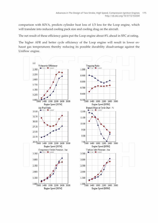
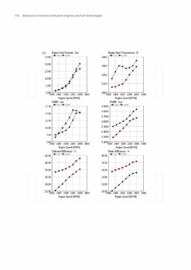
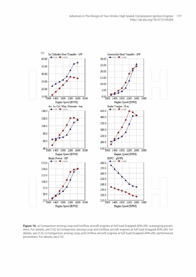
Finally, a comparison between the best Loop and Uniflow engine is shown in figure 16. Am‐bient conditions are at sea level (pressure 1.013 bar, temperature 293 K); a trapped air-to-fuelratio of 20 is imposed at any speed, except at 2400/2600 rpm, where fueling is set in order tomeet the power target of 150 HP. The positive displacement compressor is always active:however, its displacement and speed are set in order to have a pressure ratio close to unityat maximum engine speed, so that the blower has a very small influence on scavenging andfuel efficiency.
The results have been presented against speed at full load (subject to a trapped AFR of20) to allow comparison with other CI engines. The reduction in fueling at 2400/2600rpmto respect the target rating has the effect of increasing the trapped AFR above 20 therebyensuring the smoke limit is also respected. This has distorted the results away from apure engine characteristic and inflected some of the curves, most notably the % burnedmass at cycle start.
In a real aircraft application the results at full load and lower speeds are of little interest, dueto the propeller loading curve. Furthermore, it can be seen that there is little torque “back‐up” as it is expected for engines without any form of turbocharger control. This is also ac‐ceptable for the aircraft application since this class of aircraft will typically be fitted with a“constant speed” propeller where the blade pitch is varied by a suitable controller or “gov‐ernor”. Indeed, a variable pitch propeller will be necessary to exploit the favorable altitudeperformance without engine over-speed.
It can be seen that the Loop engine consumes more air and requires a bigger compres‐sor, not a major disadvantage. The Uniflow engine has much better trapping ratio at lowspeed and hence low air delivery to the cylinder but this is of no advantage to the air‐craft application. At the top end of the speed range, the difference in trapping ratio is
Advances in The Design of Two-Stroke, High Speed, Compression Ignition Engineshttp://dx.doi.org/10.5772/54204
173
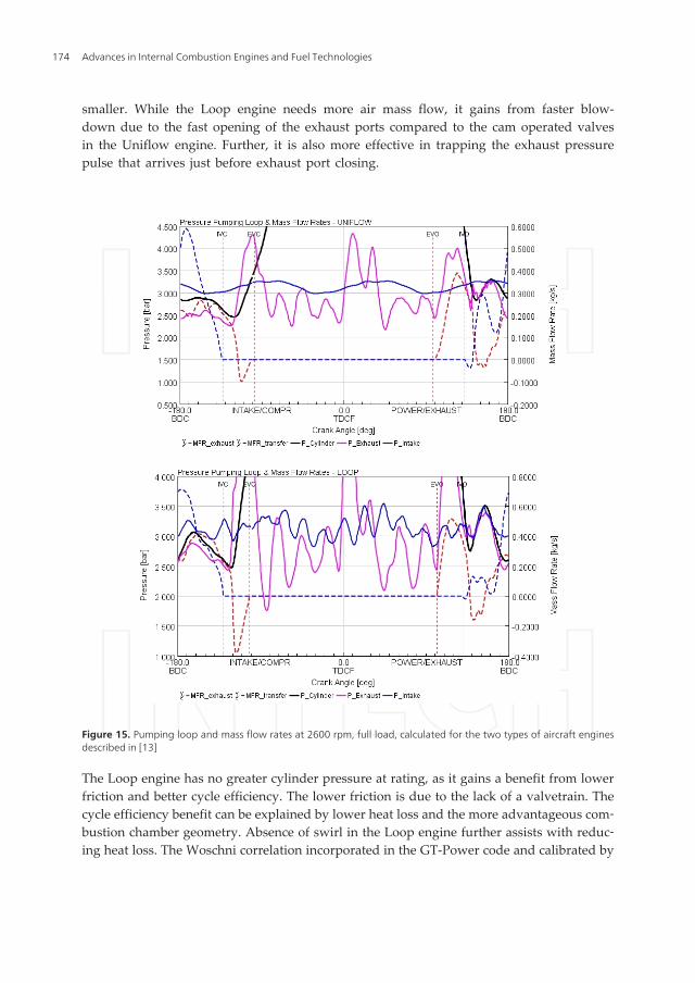
smaller. While the Loop engine needs more air mass flow, it gains from faster blow-down due to the fast opening of the exhaust ports compared to the cam operated valvesin the Uniflow engine. Further, it is also more effective in trapping the exhaust pressurepulse that arrives just before exhaust port closing.
Figure 15. Pumping loop and mass flow rates at 2600 rpm, full load, calculated for the two types of aircraft enginesdescribed in [13]
The Loop engine has no greater cylinder pressure at rating, as it gains a benefit from lowerfriction and better cycle efficiency. The lower friction is due to the lack of a valvetrain. Thecycle efficiency benefit can be explained by lower heat loss and the more advantageous com‐bustion chamber geometry. Absence of swirl in the Loop engine further assists with reduc‐ing heat loss. The Woschni correlation incorporated in the GT-Power code and calibrated by
Advances in Internal Combustion Engines and Fuel Technologies174
comparison with KIVA, predicts cylinder heat loss of 1/3 less for the Loop engine, whichwill translate into reduced cooling pack size and cooling drag on the aircraft.
The net result of these efficiency gains put the Loop engine about 8% ahead in SFC at rating.
The higher AFR and better cycle efficiency of the Loop engine will result in lower ex‐haust gas temperatures thereby reducing its possible durability disadvantage against theUniflow engine.
(a)
Advances in The Design of Two-Stroke, High Speed, Compression Ignition Engineshttp://dx.doi.org/10.5772/54204
175
(b)
Advances in Internal Combustion Engines and Fuel Technologies176
(c)
Figure 16. a) Comparison among Loop and Uniflow aircraft engines at full load (trapped AFR=20): scavenging param‐eters. For details, see [13]; b) Comparison among Loop and Uniflow aircraft engines at full load (trapped AFR=20). Fordetails, see [13]; c) Comparison among Loop and Uniflow aircraft engines at full load (trapped AFR=20): performanceparameters. For details, see [13]
Advances in The Design of Two-Stroke, High Speed, Compression Ignition Engineshttp://dx.doi.org/10.5772/54204
177
9. Conclusion
The 2-Stroke cycle combined with Compression Ignition is a promising solution for highspeed engines, particularly for small passenger cars and for light aircraft (power < 140 kW).In comparison to a corresponding 4-Stroke engine, the double cycle frequency yields the fol‐lowing advantages: higher power density, with ensuing possibility of downsizing and/ordown-speeding the engine; higher mechanical efficiency, in particular with the piston-con‐trolled ports (no valve-train); lower soot and NOx emissions at partial load, thanks to thehigher air excess; possibility of having a high content of residuals within the cylinder with‐out an external EGR system.
Since 1990, many prototypes have been designed and built, according to quite different con‐cepts. The two most interesting designs, in the authors’ opinion, are the Uniflow scavenging,with exhaust poppet valves, direct injection with bowl in the piston, and Loop scavenging,with piston controlled ports, direct injection and bowl in the cylinder head. Both solutionsadopt an external supercharging system, so that lubrication can be the same of a convention‐al 4-Stroke engine.
The uniflow design is closer to the 4-Stroke engine, and its bigger advantage is to share mostof the components with mass production engines. In particular, the combustion system andthe valve-train is the same of passenger car Diesels. Conversely, the loop design requires amuch bigger effort, since the combustion system must be developed according to new con‐cepts, and a number of minor issues concerning piston rings and liner durability must becarefully addressed. The reward for properly addressing these issues is a very compact de‐sign and an excellent mechanical efficiency.
As far as scavenging is concerned, it is a widespread opinion that Uniflow is always betterthan Loop, in terms of efficiency. This is not the final outcome of the authors’ investigations,whereas it was found that a strong support by CFD simulation can help the designer to closethe gap between the two designs and even get a higher quality of the gas exchange process.The same CFD support is the key to develop efficient combustion systems, without need of aswirl motion within the cylinder.
In this document, the development of two different 2-Stroke High Speed Direct Injected Die‐sel engines is presented for two applications: small passenger cars (1.05 liter of capacity, 3-cylinder, power target 80 kW@4000 rpm) and light aircraft (1.8 liter of capacity, 3-cylinder,power target 110 kW@2600 rpm). In both cases, the design guidelines are discussed.
The superiority of the 2-S design in comparison to the 4-S stroke cycle is demonstrated bymeans of CFD analyses, performed by means of experimentally calibrated models. In partic‐ular, the passenger car 2-S engine is able to provide, from 2250 to 4000 rpm, a brake powerhigher than the peak value of the reference 4-Stroke engine (1.25 liter, 4 cylinder, turbo‐charged, peak power 65 kW@4000 rpm). Furthermore, engine-out soot emissions at partialload are about one order of magnitude lower, while NOx can be controlled without an exter‐nal EGR system. As far as the aircraft engine is concerned, the 2-S design yields a big weightsaving in comparison to a 4-Stroke engine delivering the same power; furthermore, the air‐
Advances in Internal Combustion Engines and Fuel Technologies178
craft application requires strong modifications from the design used for passenger car en‐gines, so that the transformation of an off-the-shelf Diesel engine has a cost very close to abrand new project.
At the moment of writing this document, the field of High Speed Compression Ignition 2-Stroke engines is an open research area. A lot of ground still has to be covered in order todevelop reliable prototypes, able to practically demonstrate the theoretical advantagesfound by means of CFD simulation. In the automotive field, the concept may also find anapplication to the so-called “range-extenders”, i.e. internal combustion engines designed torecharge the batteries of electric vehicles. Here, the compactness and the low pollutant emis‐sions level of the 2-Stroke cycle could play a fundamental role. In the aircraft field, the effortwill be focused for keeping the engine design simple and reliable, in order to be competitivewith the 4-Stroke SI engines also in terms of production and installation cost.
Nomenclature
1D/3D One/Three-Dimensional
AFR Air-Fuel Ratio
Aeff,av Effective average area of transfer and exhaust ports
Ap Area of the piston (cross section)
BDC Bottom Dead Center
BMEP Brake Mean Effective Pressure
BSFC Brake Specific Fuel Consumption
CFD Computational Fluid-Dynamics
DI Direct Injection
DR Delivery Ratio
EGR Exhaust Gas Recirculation
EPO/EPC Exhaust Port Opening/Closing
EVO/EVC Exhaust Valve Opening/Closing
FMEP Friction Mean Effective Pressure
HSDI High Speed, Direct Injection
IDI In-Direct Injection
IMEP Indicated Mean Effective Pressure
Rpm Revolutions per minute
Advances in The Design of Two-Stroke, High Speed, Compression Ignition Engineshttp://dx.doi.org/10.5772/54204
179
SE Scavenging Efficiency
S.I. Spark Ignition
TDC Top Dead Center
TE Trapping Efficiency
TPO/TPC Transfer Port Opening/Closing
Up Mean Piston Speed
Δp Pressure drop across the cylinder
ρ Charge density
Acknowledgements
The author wish to acknowledge Gamma Technologies, Westmont, IL for the academic li‐cense of GT-Power, granted to the University of Modena and Reggio Emilia
Author details
Enrico Mattarelli, Giuseppe Cantore and Carlo Alberto Rinaldini
Faculty of Engineering "Enzo Ferrari", University of Modena and Reggio Emilia, Italy
References
[1] Heywood, JB. and Sher, E. The Two-Stroke Cycle Engine. Warrendale (PA): SAE In‐ternational; 1999
[2] Fleck, R and Campbell, DJ. An experimental investigation into the potential of smalltwo-stroke diesel engines. IMechE proceedings, 1991. Paper C433/061.
[3] Nomura, K and Nakamura, N. Development of a New Two-Stroke Engine with Pop‐pet-Valves: Toyota S-2 Engine. Proceedings of the International Seminar: “A NewGeneration of Two-Stroke Engines for the Future ? “ held at IFP, Rueil-Malmaison,France, November 29-30, 1993. Ed. P. Duret, pp. 53-62
[4] Knoll, R. AVL Two-Stroke Diesel Engine. SAE Paper 980757, 1998
[5] Masuda, T, Itoh, H, and Ichihara, Y. “Research on the Practical Application of 1 liter,Semi-Dl, 2-Stroke Diesel Engine to Compact Cars”. SAE Paper 1999-01-1249, 1999.
Advances in Internal Combustion Engines and Fuel Technologies180
[6] Daihatsu Motor Co., Ltd, Press Information, The 61st International Motor Show(IAA), Frankfurt 2005. Available at www.daihatsu.com. 2005.
[7] Hofbauer, P, "Opposed Piston Opposed Cylinder (opoc) Engine for Military GroundVehicles," SAE Technical Paper 2005-01-1548, 2005.
[8] Mattarelli, E., “Virtual Design of a novel 2-Stroke HSDI Diesel Engine”. Published on“International Journal of Engine Research”, Professional Engineering Publishing,June 2009 issue, Vol. 10 No 3 ISSN 1468-0874, pp. 175-193
[9] DeltaHawk Diesel Engines Website, www.deltahawkengines.com
[10] Michael Zoche Antriebstechnik Website, www.zoche.de.
[11] Diesel Air Limited Website, www.dair.co.uk.
[12] Mattarelli, E., Paltrinieri, F., Perini, F., Rinaldini, C.A. and Wilksch, M.C., “2-StrokeDiesel engine for light aircraft: IDI vs. DI combustion systems”, SAE Paper2010-01-2147. Published on October 2010
[13] Mattarelli, E., Rinaldini, C.A. and Wilksch, M.C., “2-Stroke High Speed Diesel En‐gines for Light Aircraft”, SAE International Journal of Engines, August 2011 vol. 4no. 2 2338-2360. doi: 10.4271/2011-24-0089
[14] Mattarelli, E., Rinaldini, C.A., Golovitchev, V., “”.SAE International Journal of En‐gines, August 2011 vol. 4
[15] Brouwers, A.,P. "150 and 300 kW Lightweight Diesel Aircraft Engine Design Study",NASA Contract Report 3260. NASA Scientific and Technical Information Office. 1980
[16] Fleck, B., Fleck, R., Kee, R.J., Hu, X., Foley, L. and Yavuz, I., “CFD Simulation andValidation of the Scavenging Process in a 125cc 2-Stroke Racing Engine”. SAE Paper2006-32-0061. 2006
[17] Blair, G.P., “Design and Simulation of Two-Stroke Engines”, published by Society oAutomotive Engineers, ISBN 1-56091-685-0. 1996
[18] Hori, H, “Scavenging Flow Optimization of Two-Stroke Diesel Engine by use ofCFD”. SAE Paper 2000-01-0903, 2000.
[19] Abthoff, J, Duvinage, F, Hardt, T, Kramer, M, and Paule, M, “The 2-Stroke DI-DieselEngine with Common Rail Injection for Passenger Car Application”. SAE Transac‐tions 1998 – Journal of Engines, pp 1508-1514. 1998
[20] De Marco, C.A., Mattarelli, E., Paltrinieri, F. and Rinaldini, C.A.,”A New combustionSystem for 2-Stroke HSDI Diesel Engines”. SAE paper 2007-01-1255. 2007
[21] Golovitchev, V.I., Rinaldini, C.A., Montorsi, L., Rosetti, A., “CFD combustion andemission formation modeling for a HSDI diesel engine using detailed chemistry”,ASME Internal Combustion Engine Division 2006 Fall Technical Conference; 2006,ISBN: 0791837920;978-079183792-4
Advances in The Design of Two-Stroke, High Speed, Compression Ignition Engineshttp://dx.doi.org/10.5772/54204
181
[22] Boretti, A.A., Cantore, G., Borghi, M. and Mattarelli, E., "Experimental and Computa‐tional Methods for Swirl Port Design in Internal Combustion Engines". Proceedingsof "17th Annual Fall Technical Conference of the ASME Internal Combustion EngineDivision", Milwaukee (USA), September 24-27, 1995.
[23] Mattarelli, E., Montorsi, L. and Fontanesi, S. “Numerical Analysis of Swirl ControlStrategies in a Four Valve HSDI Diesel engines”. ICEF2004-909. Proceedings of theASME 2004 Fall Technical Conference. October 24-27, 2004.
[24] Mattarelli, E., Fontanesi, S., Gagliardi, V. and Malaguti, S., “Multidimensional CycleAnalysis on a Novel 2-Stroke HSDI Diesel Engine”. SAE Paper 2007-01-0161. 2007
[25] Mattarelli, E., Fontanesi, S., Cantore, G. and Malaguti, S. “CFD-3D Multi-Cycle Anal‐ysis on a New 2-Stroke HSDI Diesel Engine”. SAE paper 2009-01-0707. 2009
Advances in Internal Combustion Engines and Fuel Technologies182
![Company profile 6 pagine · inelectra - termozulia - venezuela 'u\hu lqvshfwlrq uhsdlu dqg whvw 3ursloyhq 9hqh]xhod &rpsuhvvlrq xqlwv uhydpslqj 3'96$ &xudfdr 3urfhvv pdnh jrrg 32/,17(5](https://static.fdocuments.net/doc/165x107/606ec82ab6a06d246604810f/company-profile-6-inelectra-termozulia-venezuela-uhu-lqvshfwlrq-uhsdlu-dqg.jpg)


![KMcGratten Precon Presentation NANT10...E Ed í ì ð l î ð l î ì î ì ï ^ µ l ] v P W Z Ç ] } o } P Ç &RPSUHVVLRQ 3RVLWLYH SUHVVXUH JHQHUDWHG ZLWKLQ WKH QLSSOH DV WKH OLQJXDO](https://static.fdocuments.net/doc/165x107/5fb002d3ac75d671c469bc37/kmcgratten-precon-presentation-nant10-e-ed-l-l-.jpg)


![DM Nephropathy HASNI (2)123 (1)23 [Read-Only]soahec.org/wp-content/uploads/2018/10/Kamran-Hasni.pdf · 2018-10-10 · :kdw duh 'ldehwlfv zlwk 1hskursdwk\ '\lqj )urp" 6wurnh 0\rfdugldo,qidufwlrq](https://static.fdocuments.net/doc/165x107/5e2cff2e01680d522e7c5097/dm-nephropathy-hasni-2123-123-read-only-2018-10-10-kdw-duh-ldehwlfv-zlwk.jpg)


