18K/30K Online UPS System System Operation Turn On the System 1) After all connections are properly...
21
18K/30K Online UPS System Uninterruptible Power Supply System User Manual
-
Upload
duongthien -
Category
Documents
-
view
216 -
download
2
Transcript of 18K/30K Online UPS System System Operation Turn On the System 1) After all connections are properly...
18K/30K Online UPS System
Uninterruptible Power Supply System
User Manual
1
Please comply with all warnings and operating
instructions in this manual strictly. Save this
manual properly and read carefully the following
instructions before installing the unit. Do not
operate this unit before reading through all
safety information and operating instructions
carefully.
2
Table of Contents 1. INTRODUCTION ............................................................................................................................. 3
1.1. PRODUCT OUTLOOK ........................................................................................................................... 3
1.2. PRODUCT MAJOR FEATURE ................................................................................................................... 5
1.3. PRODUCT OVERVIEW .......................................................................................................................... 5
2. INSTALLATION ............................................................................................................................... 8
2-1. SAFETY INSTRUCTION ............................................................................................................................ 8
2-2. INSTALLATION ...................................................................................................................................... 8
3. OPERATIONS ................................................................................................................................ 10
3-1. PARALLEL SYSTEM OPERATION ............................................................................................................... 10
3-2. REPLACEMENT .................................................................................................................................... 11
3-3. DUAL MAINS INPUT (OPTIONAL) & MAINTENANCE BYPASS SWITCH OPERATION .................................................. 12
4. SINGLE UPS BUTTON AND LCD OPERATION ............................................................................... 13
4-1. BUTTON OPERATION ............................................................................................................................ 13
4-2. LED INDICATORS AND LCD PANEL .......................................................................................................... 13
4-3. AUDIBLE ALARM.................................................................................................................................. 15
4-4. FAULT CODE ...................................................................................................................................... 16
4-5. WARNING INDICATOR .......................................................................................................................... 16
5. TROUBLE SHOOTING ................................................................................................................... 17
6. BATTERY MAINTENANCE ............................................................................................................. 19
6-1. BATTERY MAINTENANCE & STORAGE ........................................................................................................ 19
6-2. IMPORTANT SAFETY CAUTION ................................................................................................................. 19
6. SPECIFICATIONS ......................................................................................................................... 20
3
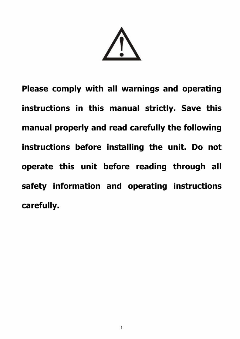
1. Introduction This modular redundant UPS system is entirely self-contained to allow each UPS module to work with complete functionality. Its modular design allows easy to service and upgrade with low cost MTTR. It also can be parallel operated with N+1 redundancy for power safety and reliability. This UPS system contains 3 sets of rack-independent online UPS modules, battery packs, and input/output transformer boxes. It’s perfect power protection for server room, data center, telecom applications and mission-critical loads.
1.1. Product Outlook
Figure 1: Front view with door closed
4
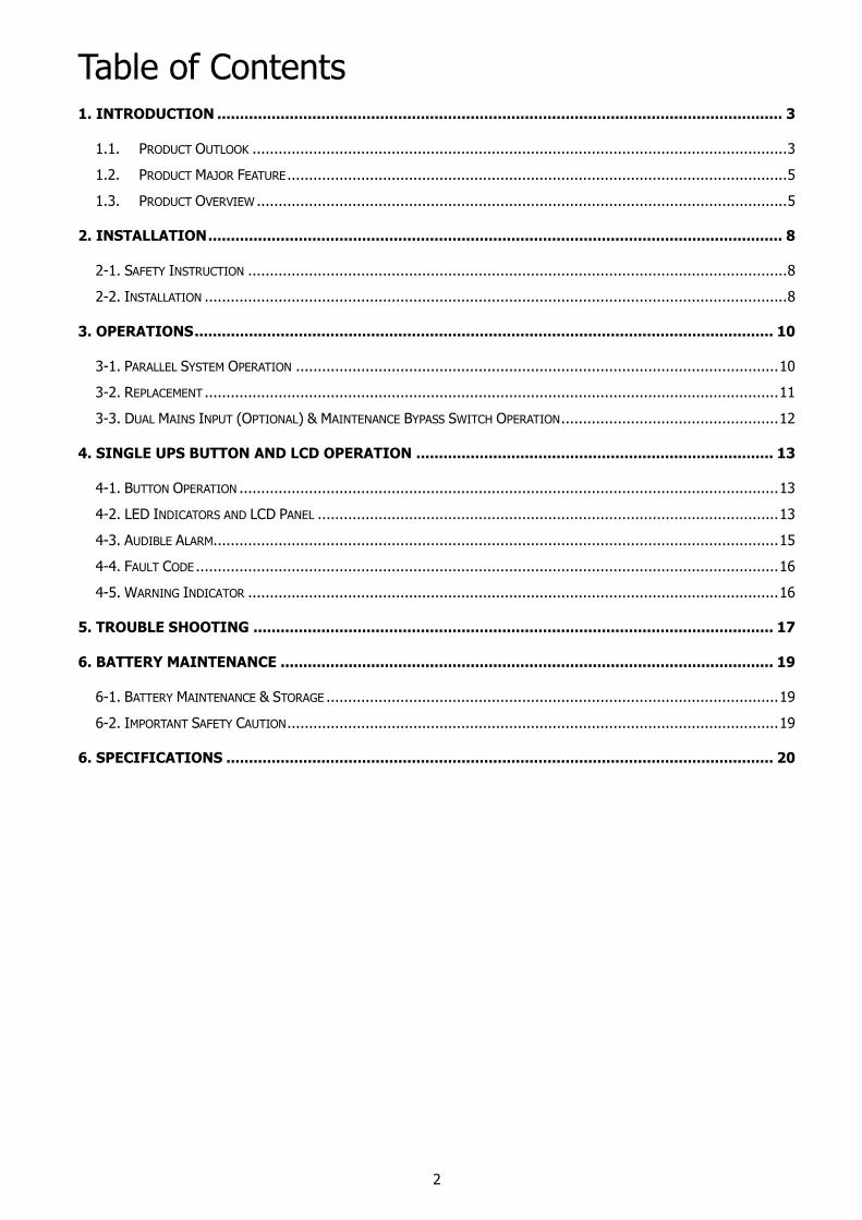
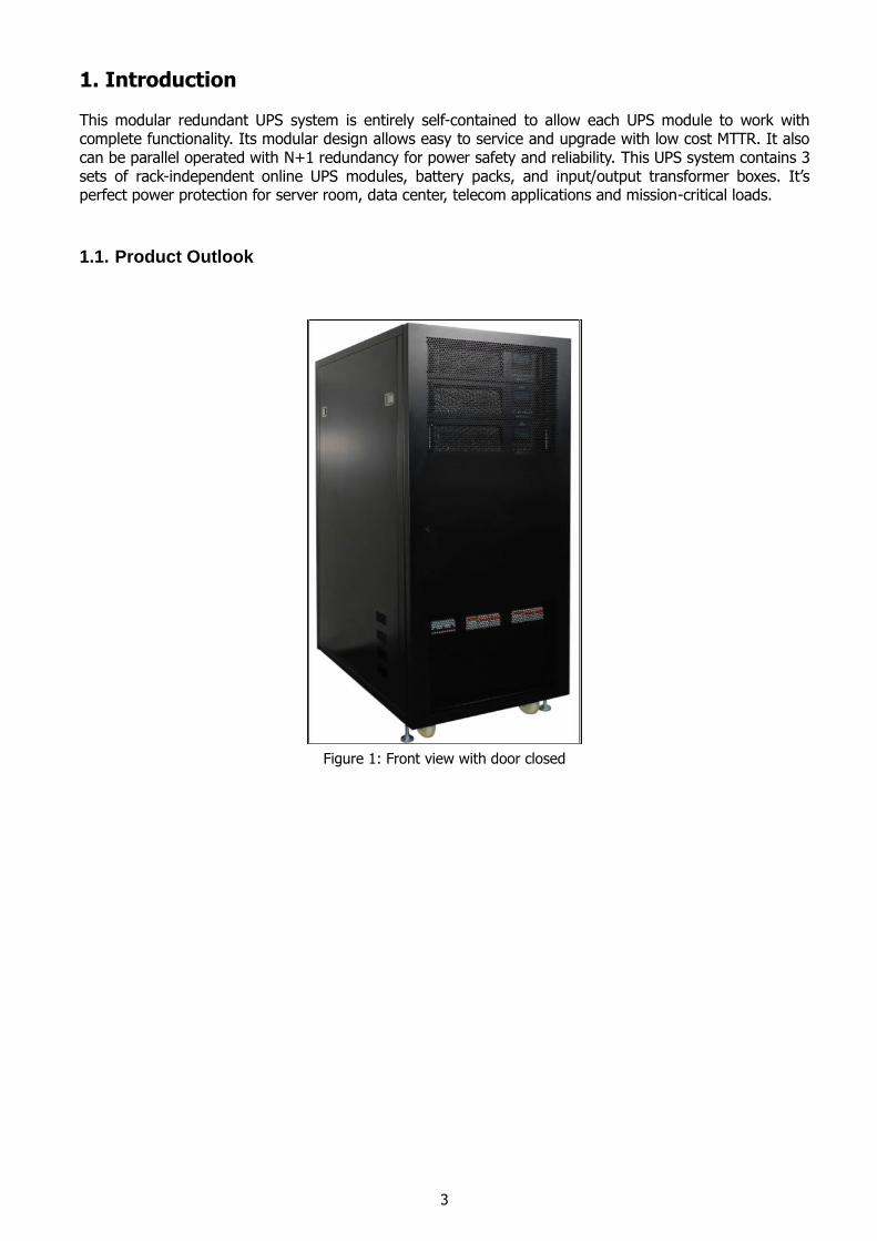
Figure 2: Front view with door opened
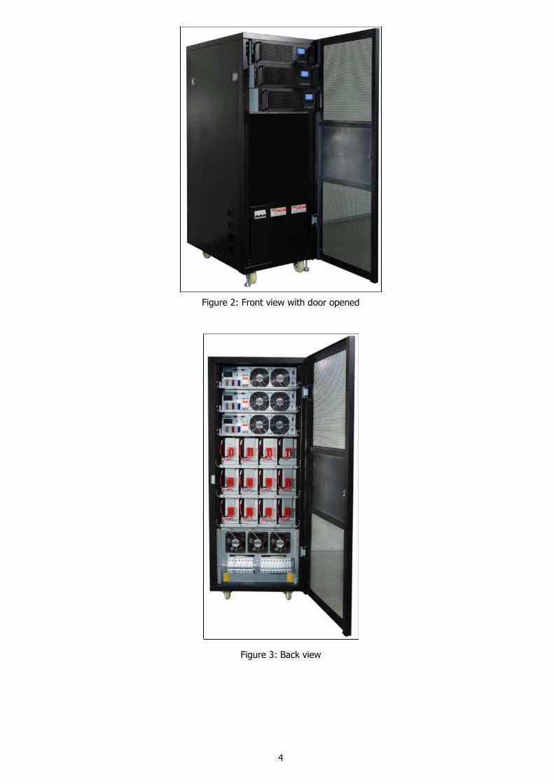
Figure 3: Back view
5
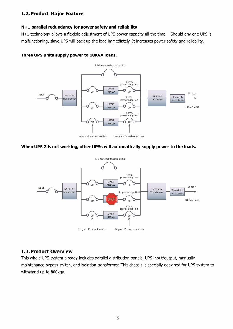
1.2. Product Major Feature
N+1 parallel redundancy for power safety and reliability
N+1 technology allows a flexible adjustment of UPS power capacity all the time. Should any one UPS is
malfunctioning, slave UPS will back up the load immediately. It increases power safety and reliability.
Three UPS units supply power to 18KVA loads.
When UPS 2 is not working, other UPSs will automatically supply power to the loads.
1.3. Product Overview
This whole UPS system already includes parallel distribution panels, UPS input/output, manually
maintenance bypass switch, and isolation transformer. This chassis is specially designed for UPS system to
withstand up to 800kgs.
6
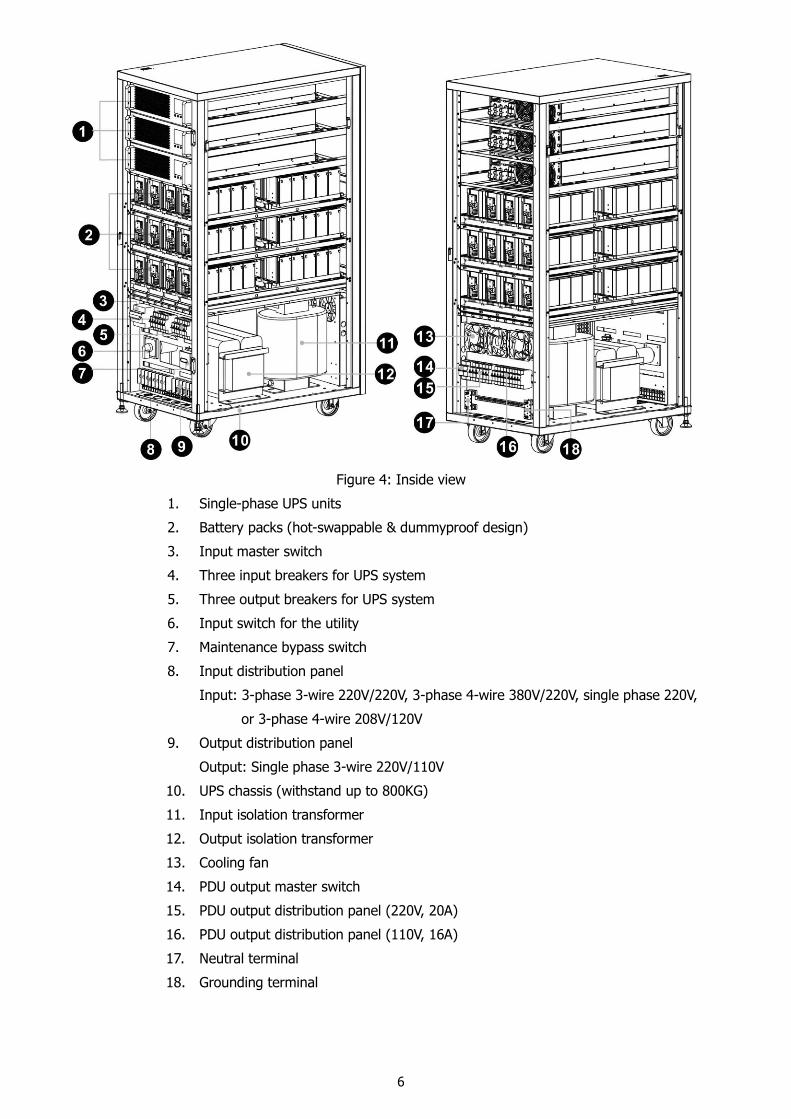
Figure 4: Inside view
1. Single-phase UPS units
2. Battery packs (hot-swappable & dummyproof design)
3. Input master switch
4. Three input breakers for UPS system
5. Three output breakers for UPS system
6. Input switch for the utility
7. Maintenance bypass switch
8. Input distribution panel
Input: 3-phase 3-wire 220V/220V, 3-phase 4-wire 380V/220V, single phase 220V,
or 3-phase 4-wire 208V/120V
9. Output distribution panel
Output: Single phase 3-wire 220V/110V
10. UPS chassis (withstand up to 800KG)
11. Input isolation transformer
12. Output isolation transformer
13. Cooling fan
14. PDU output master switch
15. PDU output distribution panel (220V, 20A)
16. PDU output distribution panel (110V, 16A)
17. Neutral terminal
18. Grounding terminal
7
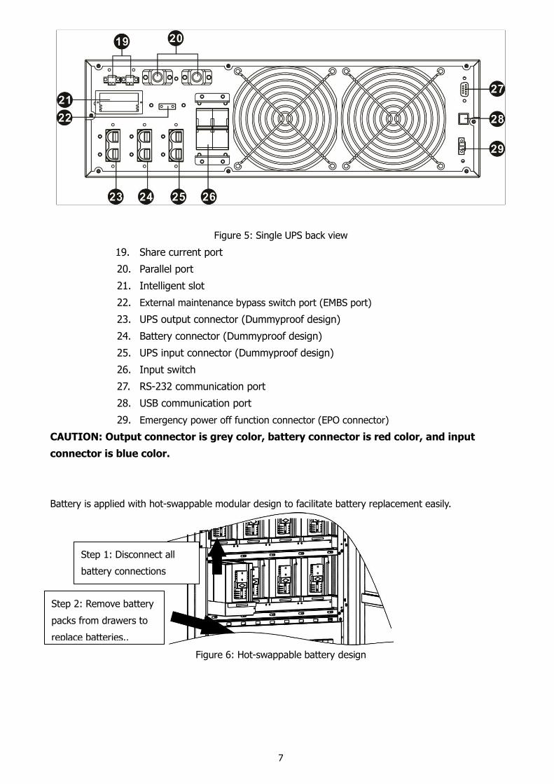
Figure 5: Single UPS back view
19. Share current port
20. Parallel port
21. Intelligent slot
22. External maintenance bypass switch port (EMBS port)
23. UPS output connector (Dummyproof design)
24. Battery connector (Dummyproof design)
25. UPS input connector (Dummyproof design)
26. Input switch
27. RS-232 communication port
28. USB communication port
29. Emergency power off function connector (EPO connector)
CAUTION: Output connector is grey color, battery connector is red color, and input
connector is blue color.
Battery is applied with hot-swappable modular design to facilitate battery replacement easily.
Figure 6: Hot-swappable battery design
Step 1: Disconnect all
battery connections
Step 2: Remove battery
packs from drawers to
replace batteries..
8
2. Installation
2-1. Safety Instruction
1) The UPS must be installed in the room where it is ventilated and dry. Do not install the UPS system near water, flammable liquid, or corrosive substance.
2) Do not block ventilation holes in the UPS chassis. The UPS must be installed in a location with good ventilation. Ensure enough space (at least 0.5m) on each side for ventilation.
3) Condensation may occur if the UPS system is unpacked under cold environment. The UPS system must be absolutely dry before being installed. Otherwise, it may cause electric shocks. Please wait until the inside and outside of UPS system is absolutely dry.
2-2. Installation
Installation and wiring must be performed in accordance with the local electric laws/regulations and execute the following instructions by professional personnel. For safety consideration, please cut off the input utility power before installation. If connecting external batteries, please be sure to cut off battery connection first before installation.
1) Remove the back panel of UPS input/output distribution box.
2) Please use proper wires according to local electric laws/regulation and future expansion plan.
CAUTION: It’s strongly recommended that the circuit is exclusively for UPS input, not shared with others.
The input switch should withstand at least the maximum input current of the UPS.
3) Connect input and output wires on input and output terminals.
CAUTION: Be sure to connect all wires firmly.
4) Please connect two yellow/green wires. One wire is connected to grounding terminal on the UPS
input distribution panel and the other wire is connected to grounding terminal of the loads.
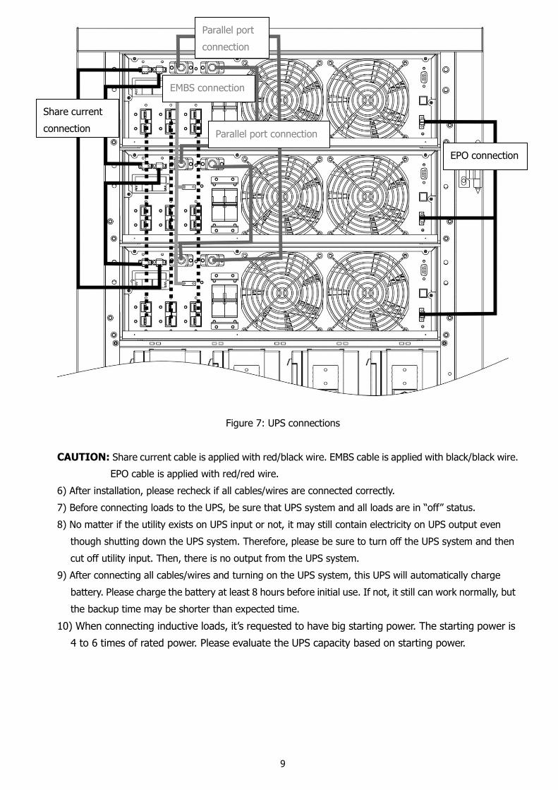
5) Connect all input/output (dotted lines), battery (dotted line), parallel port (grey lines), EPO port
(black lines), EMBS port (light grey lines), and share current port (black lines) on the back panel of
each UPS unit. Refer to below figure.
9
Figure 7: UPS connections
CAUTION: Share current cable is applied with red/black wire. EMBS cable is applied with black/black wire.
EPO cable is applied with red/red wire.
6) After installation, please recheck if all cables/wires are connected correctly.
7) Before connecting loads to the UPS, be sure that UPS system and all loads are in “off” status.
8) No matter if the utility exists on UPS input or not, it may still contain electricity on UPS output even
though shutting down the UPS system. Therefore, please be sure to turn off the UPS system and then
cut off utility input. Then, there is no output from the UPS system.
9) After connecting all cables/wires and turning on the UPS system, this UPS will automatically charge
battery. Please charge the battery at least 8 hours before initial use. If not, it still can work normally, but
the backup time may be shorter than expected time.
10) When connecting inductive loads, it’s requested to have big starting power. The starting power is
4 to 6 times of rated power. Please evaluate the UPS capacity based on starting power.
EPO connection
Parallel port
connection
EMBS connection
Share current
connection Parallel port connection
10
3. Operations
3-1. Parallel System Operation
Turn On the System
1) After all connections are properly installed, please turn “ON” UPS master switch and switch input breaker
of all UPSs to “ON” status. Then, turn “ON” input switch of each UPS unit. The cooling fan will start to
operate at the same time. All LEDs on front panels will light up. After initialization, only bypass LED will
light up. Then, all UPSs will operate under bypass mode.
2) Please turn on each UPS one by one in one minute (press “ON” button for 1 second to turn on UPS). A
few seconds later, all UPSs will enter to AC mode and LINE indicator on each UPS will light up. It will
display “PAR 001~003” in order. The parallel system connection is complete. Then, turn on the output
breaker of all UPSs.
CAUTION: Before operation, please measure the voltage difference between the output line of each
UPS with multimeter. Be sure that the output voltage difference should be less than 1V. If the difference
is larger than 1V, please adjust inverter voltage via LCD operation. Please refer to single UPS manual for
detailed LCD operation.
Turn Off the System
1) Turn off each UPS one by one in one minute (press “OFF” button for 1 second to turn off UPS). A few
seconds later, all UPSs will transfer to bypass mode.
CAUTION: If only removing one UPS, please press “OFF” button twice on the removing UPS and each
time should last for more than 0.5s. Then, this UPS will enter into bypass mode without output. The
other two UPSs will parallel operate normally.
2) Until now, there is bypass output from the UPS system. If shutting down output of this system completely,
please turn off input breakers on back panel of each UPS, input master switch, and input breakers for all
UPSs on the distribution panel. Then, this UPS will save all data and LCD panel will be still on at the same
time. After a few seconds, the LCD display will shut off. This UPS system is completely off now.
CAUTION: Be sure to wait until the UPS system is completely turned on and operated, then, turn on the
power of connected load. Therefore, before shutting down UPS system, please turn off all power of
connected loads first.
11
3-2. Replacement
UPS Replacement
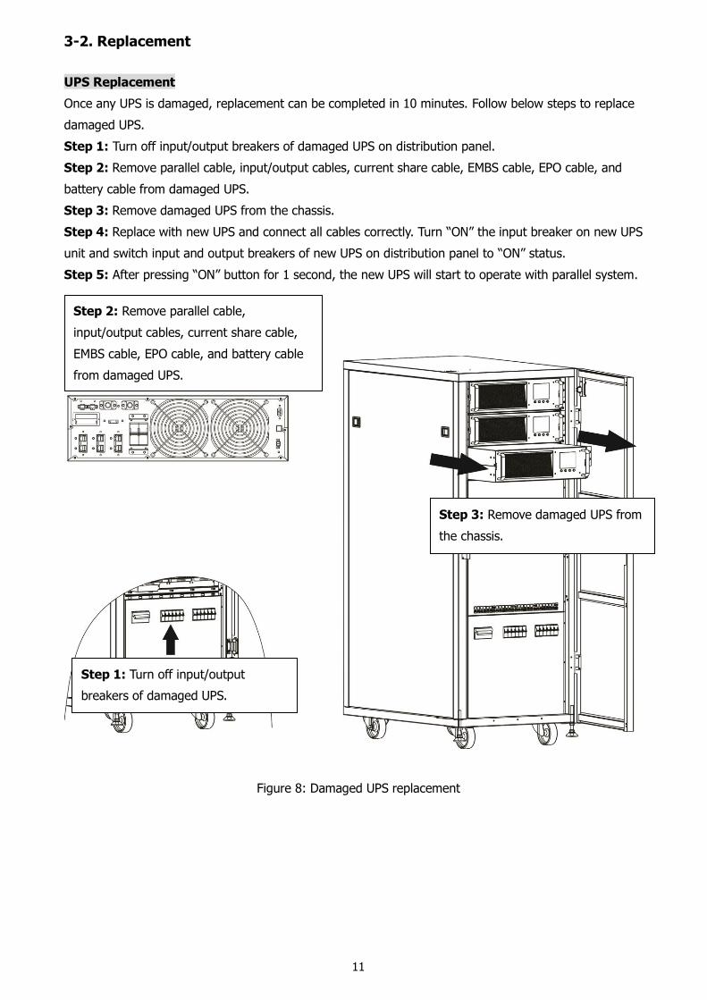
Once any UPS is damaged, replacement can be completed in 10 minutes. Follow below steps to replace
damaged UPS.
Step 1: Turn off input/output breakers of damaged UPS on distribution panel.
Step 2: Remove parallel cable, input/output cables, current share cable, EMBS cable, EPO cable, and
battery cable from damaged UPS.
Step 3: Remove damaged UPS from the chassis.
Step 4: Replace with new UPS and connect all cables correctly. Turn “ON” the input breaker on new UPS
unit and switch input and output breakers of new UPS on distribution panel to “ON” status.
Step 5: After pressing “ON” button for 1 second, the new UPS will start to operate with parallel system.
Figure 8: Damaged UPS replacement
Step 3: Remove damaged UPS from
the chassis.
Step 2: Remove parallel cable,
input/output cables, current share cable,
EMBS cable, EPO cable, and battery cable
from damaged UPS.
Step 1: Turn off input/output
breakers of damaged UPS.
12
Battery Replacement
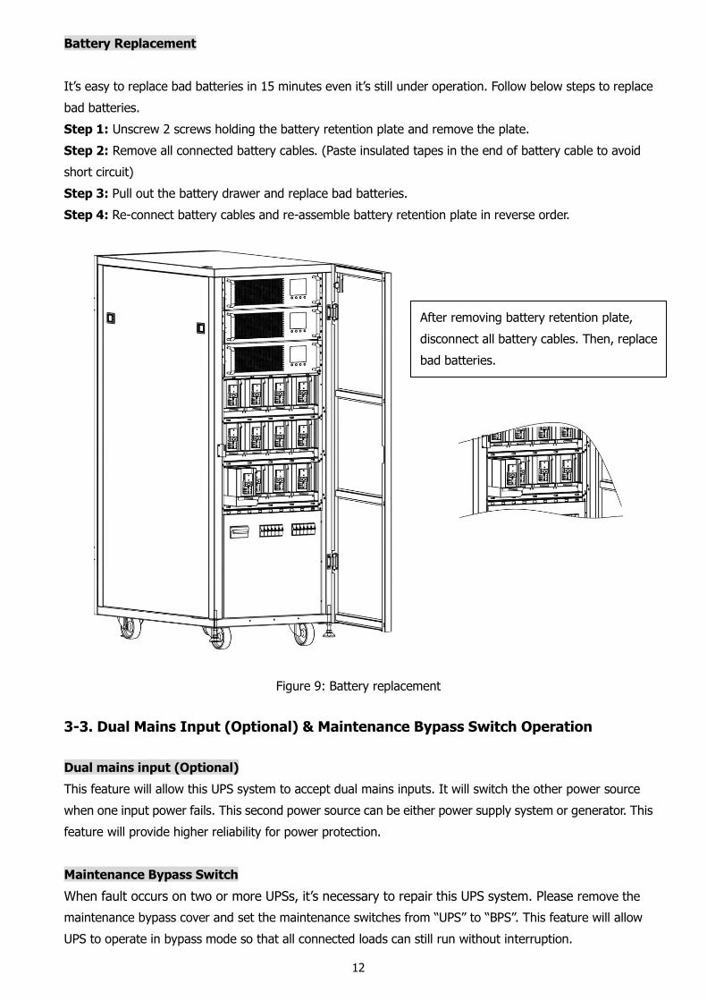
It’s easy to replace bad batteries in 15 minutes even it’s still under operation. Follow below steps to replace
bad batteries.
Step 1: Unscrew 2 screws holding the battery retention plate and remove the plate.
Step 2: Remove all connected battery cables. (Paste insulated tapes in the end of battery cable to avoid
short circuit)
Step 3: Pull out the battery drawer and replace bad batteries.
Step 4: Re-connect battery cables and re-assemble battery retention plate in reverse order.
Figure 9: Battery replacement
3-3. Dual Mains Input (Optional) & Maintenance Bypass Switch Operation
Dual mains input (Optional)
This feature will allow this UPS system to accept dual mains inputs. It will switch the other power source
when one input power fails. This second power source can be either power supply system or generator. This
feature will provide higher reliability for power protection.
Maintenance Bypass Switch
When fault occurs on two or more UPSs, it’s necessary to repair this UPS system. Please remove the
maintenance bypass cover and set the maintenance switches from “UPS” to “BPS”. This feature will allow
UPS to operate in bypass mode so that all connected loads can still run without interruption.
After removing battery retention plate,
disconnect all battery cables. Then, replace
bad batteries.
13
4. Single UPS Button and LCD Operation
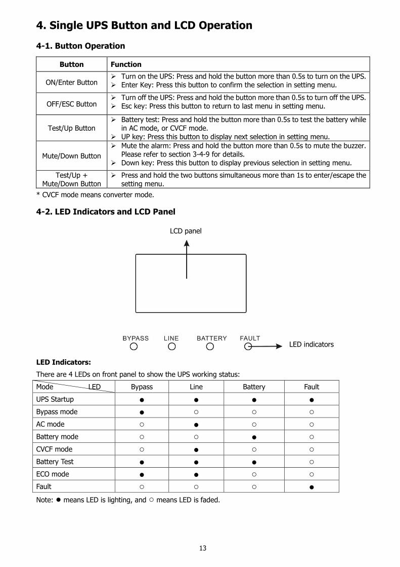
4-1. Button Operation
Button Function
ON/Enter Button Turn on the UPS: Press and hold the button more than 0.5s to turn on the UPS. Enter Key: Press this button to confirm the selection in setting menu.
OFF/ESC Button Turn off the UPS: Press and hold the button more than 0.5s to turn off the UPS. Esc key: Press this button to return to last menu in setting menu.
Test/Up Button Battery test: Press and hold the button more than 0.5s to test the battery while
in AC mode, or CVCF mode. UP key: Press this button to display next selection in setting menu.
Mute/Down Button
Mute the alarm: Press and hold the button more than 0.5s to mute the buzzer. Please refer to section 3-4-9 for details.
Down key: Press this button to display previous selection in setting menu.
Test/Up + Mute/Down Button
Press and hold the two buttons simultaneous more than 1s to enter/escape the setting menu.
* CVCF mode means converter mode.
4-2. LED Indicators and LCD Panel
LED Indicators:
There are 4 LEDs on front panel to show the UPS working status:
Mode LED Bypass Line Battery Fault
UPS Startup ● ● ● ● Bypass mode ● ○ ○ ○
AC mode ○ ● ○ ○
Battery mode ○ ○ ● ○
CVCF mode ○ ● ○ ○
Battery Test ● ● ● ○
ECO mode ● ● ○ ○
Fault ○ ○ ○ ●
Note: ● means LED is lighting, and ○ means LED is faded.
LCD panel
LED indicators
14
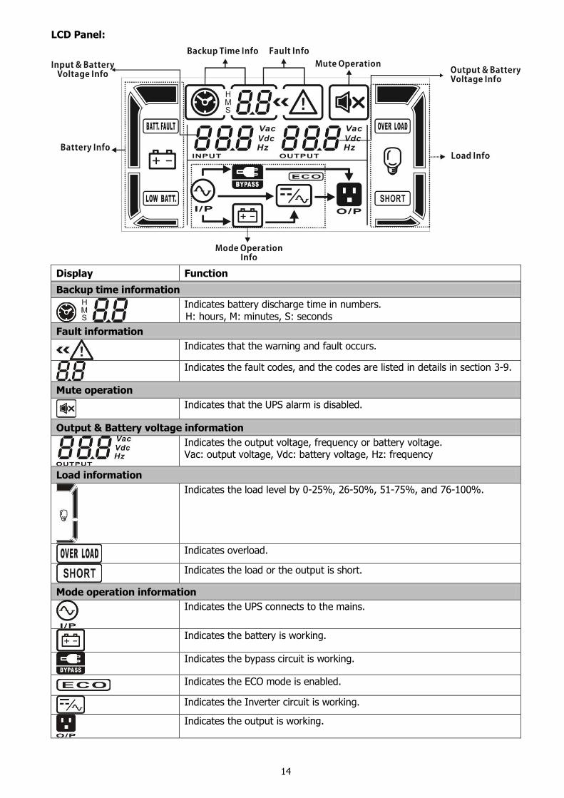
LCD Panel:
Display Function
Backup time information
Indicates battery discharge time in numbers. H: hours, M: minutes, S: seconds
Fault information
Indicates that the warning and fault occurs.
Indicates the fault codes, and the codes are listed in details in section 3-9.
Mute operation
Indicates that the UPS alarm is disabled.
Output & Battery voltage information
Indicates the output voltage, frequency or battery voltage. Vac: output voltage, Vdc: battery voltage, Hz: frequency
Load information
Indicates the load level by 0-25%, 26-50%, 51-75%, and 76-100%.
Indicates overload.
Indicates the load or the output is short.
Mode operation information
Indicates the UPS connects to the mains.
Indicates the battery is working.
Indicates the bypass circuit is working.
Indicates the ECO mode is enabled.
Indicates the Inverter circuit is working.
Indicates the output is working.
15
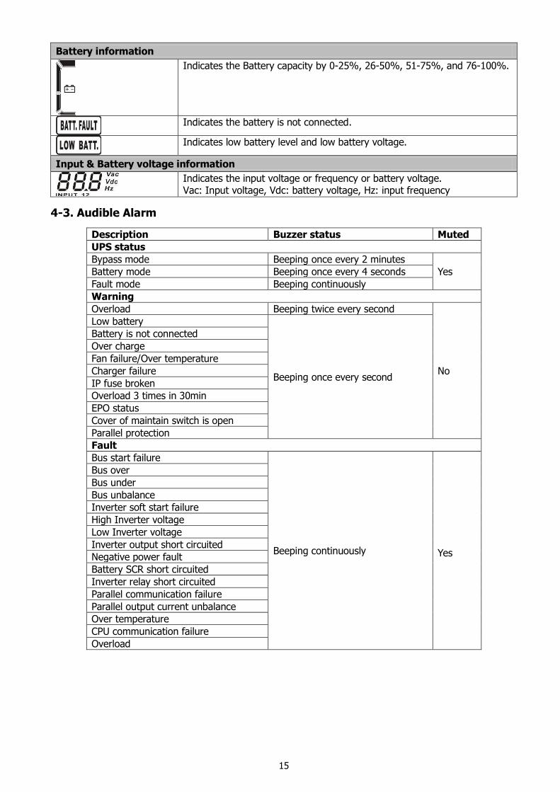
Battery information
Indicates the Battery capacity by 0-25%, 26-50%, 51-75%, and 76-100%.
Indicates the battery is not connected.
Indicates low battery level and low battery voltage.
Input & Battery voltage information
Indicates the input voltage or frequency or battery voltage. Vac: Input voltage, Vdc: battery voltage, Hz: input frequency
4-3. Audible Alarm
Description Buzzer status Muted
UPS status
Bypass mode Beeping once every 2 minutes
Yes Battery mode Beeping once every 4 seconds
Fault mode Beeping continuously
Warning
Overload Beeping twice every second
No
Low battery
Beeping once every second
Battery is not connected
Over charge
Fan failure/Over temperature
Charger failure
IP fuse broken
Overload 3 times in 30min
EPO status
Cover of maintain switch is open
Parallel protection
Fault
Bus start failure
Beeping continuously Yes
Bus over
Bus under
Bus unbalance
Inverter soft start failure
High Inverter voltage
Low Inverter voltage
Inverter output short circuited
Negative power fault
Battery SCR short circuited
Inverter relay short circuited
Parallel communication failure
Parallel output current unbalance
Over temperature
CPU communication failure
Overload
16
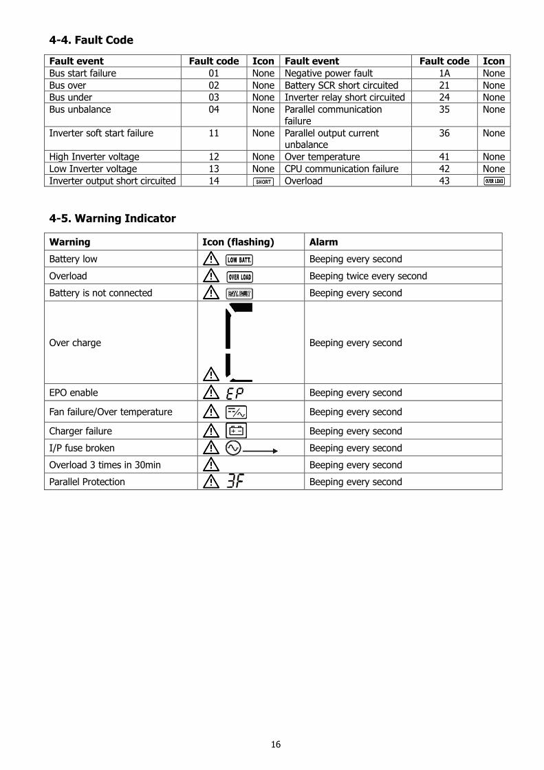
4-4. Fault Code
Fault event Fault code Icon Fault event Fault code Icon
Bus start failure 01 None Negative power fault 1A None
Bus over 02 None Battery SCR short circuited 21 None
Bus under 03 None Inverter relay short circuited 24 None
Bus unbalance 04 None Parallel communication failure
35 None
Inverter soft start failure 11 None Parallel output current unbalance
36 None
High Inverter voltage 12 None Over temperature 41 None
Low Inverter voltage 13 None CPU communication failure 42 None
Inverter output short circuited 14 Overload 43
4-5. Warning Indicator
Warning Icon (flashing) Alarm
Battery low Beeping every second
Overload Beeping twice every second
Battery is not connected Beeping every second
Over charge
Beeping every second
EPO enable Beeping every second
Fan failure/Over temperature Beeping every second
Charger failure Beeping every second
I/P fuse broken Beeping every second
Overload 3 times in 30min Beeping every second
Parallel Protection Beeping every second
17
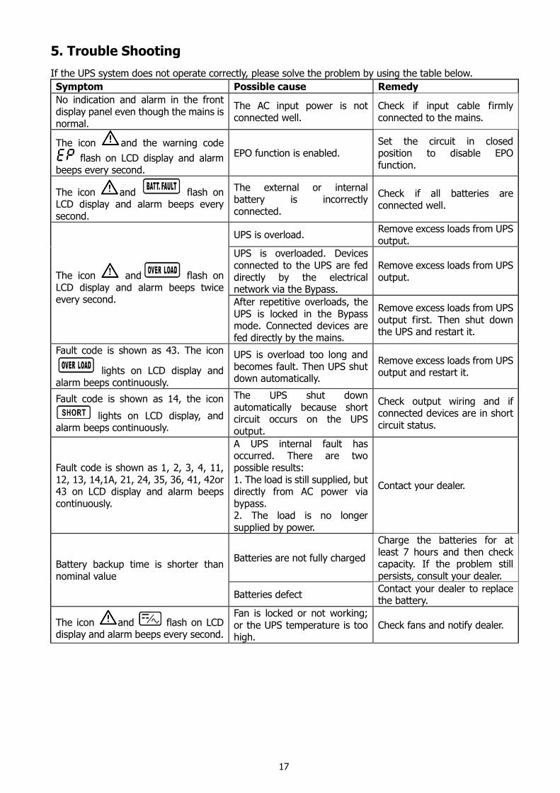
5. Trouble Shooting
If the UPS system does not operate correctly, please solve the problem by using the table below.
Symptom Possible cause Remedy
No indication and alarm in the front display panel even though the mains is normal.
The AC input power is not connected well.
Check if input cable firmly connected to the mains.
The icon and the warning code
flash on LCD display and alarm beeps every second.
EPO function is enabled. Set the circuit in closed position to disable EPO function.
The icon and flash on LCD display and alarm beeps every second.
The external or internal battery is incorrectly connected.
Check if all batteries are connected well.
The icon and flash on LCD display and alarm beeps twice every second.
UPS is overload. Remove excess loads from UPS output.
UPS is overloaded. Devices connected to the UPS are fed directly by the electrical network via the Bypass.
Remove excess loads from UPS output.
After repetitive overloads, the UPS is locked in the Bypass mode. Connected devices are fed directly by the mains.
Remove excess loads from UPS output first. Then shut down the UPS and restart it.
Fault code is shown as 43. The icon
lights on LCD display and alarm beeps continuously.
UPS is overload too long and becomes fault. Then UPS shut down automatically.
Remove excess loads from UPS output and restart it.
Fault code is shown as 14, the icon
lights on LCD display, and alarm beeps continuously.
The UPS shut down automatically because short circuit occurs on the UPS output.
Check output wiring and if connected devices are in short circuit status.
Fault code is shown as 1, 2, 3, 4, 11, 12, 13, 14,1A, 21, 24, 35, 36, 41, 42or 43 on LCD display and alarm beeps continuously.
A UPS internal fault has occurred. There are two possible results: 1. The load is still supplied, but directly from AC power via bypass. 2. The load is no longer supplied by power.
Contact your dealer.
Battery backup time is shorter than nominal value
Batteries are not fully charged
Charge the batteries for at least 7 hours and then check capacity. If the problem still persists, consult your dealer.
Batteries defect Contact your dealer to replace the battery.
The icon and flash on LCD display and alarm beeps every second.
Fan is locked or not working; or the UPS temperature is too high.
Check fans and notify dealer.
18
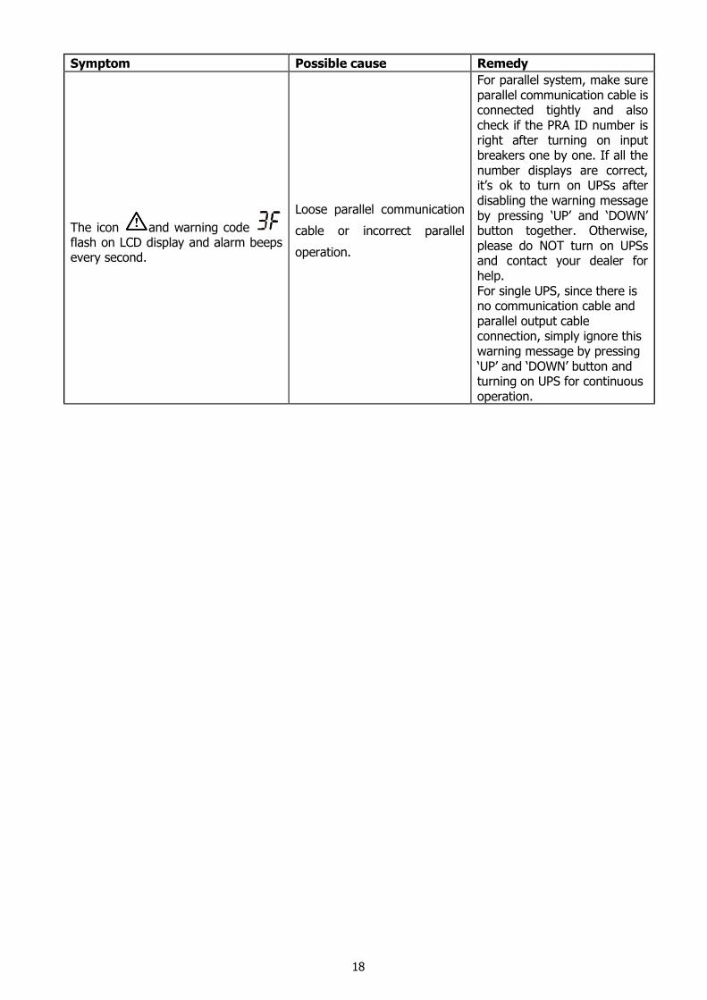
Symptom Possible cause Remedy
The icon and warning code flash on LCD display and alarm beeps every second.
Loose parallel communication
cable or incorrect parallel
operation.
For parallel system, make sure parallel communication cable is connected tightly and also check if the PRA ID number is right after turning on input breakers one by one. If all the number displays are correct, it’s ok to turn on UPSs after disabling the warning message by pressing ‘UP’ and ‘DOWN’ button together. Otherwise, please do NOT turn on UPSs and contact your dealer for help. For single UPS, since there is no communication cable and parallel output cable connection, simply ignore this warning message by pressing ‘UP’ and ‘DOWN’ button and turning on UPS for continuous operation.
19
6. Battery Maintenance
6-1. Battery Maintenance & Storage
This UPS is applied with maintenance-free sealed lead acid batteries. When this UPS is connected
to the utility, it will automatically charge battery no matter this UPS is on or not. It also offers
overcharge and over-discharge protection.
Before storing this UPS for long-time period, charge the UPS every 4-6 months. Under
environment with high temperature, please charge and discharge the UPS every 2 months. The
charging duration should last at least 12 hours each time.
It’s usually 3-year lifecycle for battery when working in the temperature of 25°C. If battery is
detected abnormal, be sure to replace it ASAP. Battery replacement should be performed or
supervised by personnel knowledgeable of batteries and the required precautions. Keep
unauthorized personnel away from batteries.
When replacing the batteries, use the same number and type of batteries.
Please replace all batteries in the same time and follow instructions from battery supplier. It’s not
recommended to replace single battery in a time.
If UPS system seldom discharges battery, please discharge battery until UPS shuts down every 4-6
months and recharge battery at least 12 hours. Be sure to discharge battery with at least 50% loads
connected.
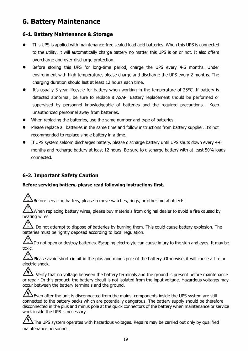
6-2. Important Safety Caution
Before servicing battery, please read following instructions first.
Before servicing battery, please remove watches, rings, or other metal objects.
When replacing battery wires, please buy materials from original dealer to avoid a fire caused by heating wires.
Do not attempt to dispose of batteries by burning them. This could cause battery explosion. The batteries must be rightly deposed according to local regulation.
Do not open or destroy batteries. Escaping electrolyte can cause injury to the skin and eyes. It may be toxic.
Please avoid short circuit in the plus and minus pole of the battery. Otherwise, it will cause a fire or electric shock.
Verify that no voltage between the battery terminals and the ground is present before maintenance or repair. In this product, the battery circuit is not isolated from the input voltage. Hazardous voltages may occur between the battery terminals and the ground.
Even after the unit is disconnected from the mains, components inside the UPS system are still connected to the battery packs which are potentially dangerous. The battery supply should be therefore disconnected in the plus and minus pole at the quick connectors of the battery when maintenance or service work inside the UPS is necessary.
The UPS system operates with hazardous voltages. Repairs may be carried out only by qualified
maintenance personnel.
20
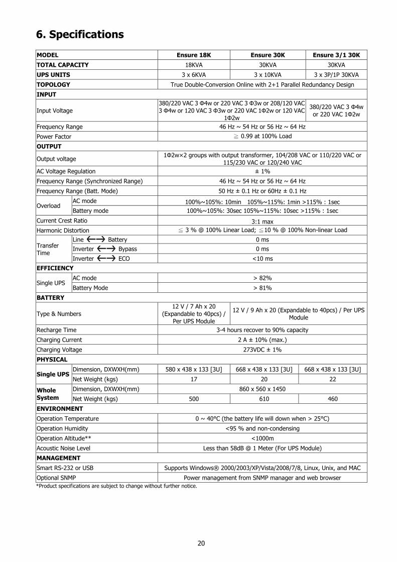
6. Specifications
MODEL Ensure 18K Ensure 30K Ensure 3/1 30K
TOTAL CAPACITY 18KVA 30KVA 30KVA
UPS UNITS 3 x 6KVA 3 x 10KVA 3 x 3P/1P 30KVA
TOPOLOGY True Double-Conversion Online with 2+1 Parallel Redundancy Design
INPUT
Input Voltage
380/220 VAC 3 Φ4w or 220 VAC 3 Φ3w or 208/120 VAC
3 Φ4w or 120 VAC 3 Φ3w or 220 VAC 1Φ2w or 120 VAC
1Φ2w
380/220 VAC 3 Φ4w
or 220 VAC 1Φ2w
Frequency Range 46 Hz ~ 54 Hz or 56 Hz ~ 64 Hz
Power Factor ≧ 0.99 at 100% Load
OUTPUT
Output voltage 1Φ2w×2 groups with output transformer, 104/208 VAC or 110/220 VAC or
115/230 VAC or 120/240 VAC
AC Voltage Regulation ± 1%
Frequency Range (Synchronized Range) 46 Hz ~ 54 Hz or 56 Hz ~ 64 Hz
Frequency Range (Batt. Mode) 50 Hz ± 0.1 Hz or 60Hz ± 0.1 Hz
Overload AC mode 100%~105%: 10min 105%~115%: 1min >115% : 1sec
Battery mode 100%~105%: 30sec 105%~115%: 10sec >115% : 1sec
Current Crest Ratio 3:1 max
Harmonic Distortion ≦ 3 % @ 100% Linear Load; ≦10 % @ 100% Non-linear Load
Transfer
Time
Line Battery 0 ms
Inverter Bypass 0 ms
Inverter ECO <10 ms
EFFICIENCY
Single UPS AC mode > 82%
Battery Mode > 81%
BATTERY
Type & Numbers
12 V / 7 Ah x 20
(Expandable to 40pcs) /
Per UPS Module
12 V / 9 Ah x 20 (Expandable to 40pcs) / Per UPS
Module
Recharge Time 3-4 hours recover to 90% capacity
Charging Current 2 A ± 10% (max.)
Charging Voltage 273VDC ± 1%
PHYSICAL
Single UPS Dimension, DXWXH(mm) 580 x 438 x 133 [3U] 668 x 438 x 133 [3U] 668 x 438 x 133 [3U]
Net Weight (kgs) 17 20 22
Whole
System
Dimension, DXWXH(mm) 860 x 560 x 1450
Net Weight (kgs) 500 610 460
ENVIRONMENT
Operation Temperature 0 ~ 40°C (the battery life will down when > 25°C)
Operation Humidity <95 % and non-condensing
Operation Altitude** <1000m
Acoustic Noise Level Less than 58dB @ 1 Meter (For UPS Module)
MANAGEMENT
Smart RS-232 or USB Supports Windows® 2000/2003/XP/Vista/2008/7/8, Linux, Unix, and MAC
Optional SNMP Power management from SNMP manager and web browser
*Product specifications are subject to change without further notice.