
:1.83. - International Society for Photogrammetry and … · an accuracy of 3 mm for large...
8
PRECISION PHOTOGRAMMETRY FOR INDUSTRIAL PURPOSES by Dr . W. Faig Professor of Surveying Engineering University of New Brunswick Fredericton, N. B., Canada Presented paper Commission V 14th Congress of the International Society for Photogrammetry Hamburg, W. Germany, 1980 Abstract In this paper, the application of close range photogrammetry for precision engineering projects is discussed using examples from shipbuilding - respectively power generating industries . Stereo photogrammetry was used to determine milling dimensions to an accuracy of 3 mm for large subassemblies of spherical tanks for liquified natural gas, while mono photogrammetry was applied for the determination of diameters of a penstock feeding turbines . Zusammenfassung Der Einsatz der Nahbereichsphotogrammetrie fur Prazisionsmessungen im Ingenieurbereich wird an Hand zweier Beispiele aus der Industrie (Schiffbau bzw . Kraftwerk) Die Dimensionen grosser Teilmontagen von kugelformigen Behaltern ftr verflussigtes Erdgas wurden mittels Stereophotogrammetrie auf 3 mm genau bestimmt, wahrend Monophotogrammetrie zur Durchmesserbestimmung von Zulaufrohren fur Turbinen eingestzt wurde . Introduction One of the key problems in our modern society is the ever increasing demand for energy . Natural resources are harnessed and transported in ways, which continue to provide challenges for engineers . Although often over- looked, photogrammetry is a useful tool for many of these engineering projects as illustrated by two applications from the energy sector, namely the determination of milling dimensions for subassemblies of spherical tanks for liquified natural gas (LNG), and of the diameters of a penstock feeding turbines below a power dam . Tank Component Survey Due to the pressure- and temperature controlled state of LNG, a spherical container,having a minimum surface for a certain volume,provides the best solution . Therefore, modern LNG tankers are equipped with a number of spherical containers . Stringent tolerances, permitting less than two centimetres deviation from the design values, require high precision work, considering the size of the spheres (radius of 18 .3 m) . [6] :1.83.
Transcript of :1.83. - International Society for Photogrammetry and … · an accuracy of 3 mm for large...

PRECISION PHOTOGRAMMETRY FOR INDUSTRIAL PURPOSES
by
Dr . W. Faig Professor of Surveying Engineering
University of New Brunswick Fredericton, N. B., Canada
Presented paper Commission V
14th Congress of the International Society for Photogrammetry Hamburg, W. Germany, 1980
Abstract
In this paper, the application of close range photogrammetry for precision engineering projects is discussed using examples from shipbuilding - respectively power generating industries .
Stereo photogrammetry was used to determine milling dimensions to an accuracy of 3 mm for large subassemblies of spherical tanks for liquified natural gas, while mono photogrammetry was applied for the determination of diameters of a penstock feeding turbines .
Zusammenfassung
Der Einsatz der Nahbereichsphotogrammetrie fur Prazisionsmessungen im Ingenieurbereich wird an Hand zweier Beispiele aus der Industrie (Schiffbau bzw . Kraftwerk) erl~utert .
Die Dimensionen grosser Teilmontagen von kugelformigen Behaltern ftr verflussigtes Erdgas wurden mittels Stereophotogrammetrie auf 3 mm genau bestimmt, wahrend Monophotogrammetrie zur Durchmesserbestimmung von Zulaufrohren fur Turbinen eingestzt wurde .
Introduction
One of the key problems in our modern society is the ever increasing demand for energy . Natural resources are harnessed and transported in ways, which continue to provide challenges for engineers . Although often overlooked, photogrammetry is a useful tool for many of these engineering projects as illustrated by two applications from the energy sector, namely the determination of milling dimensions for subassemblies of spherical tanks for liquified natural gas (LNG), and of the diameters of a penstock feeding turbines below a power dam .
Tank Component Survey
Due to the pressure- and temperature controlled state of LNG, a spherical container,having a minimum surface for a certain volume,provides the best solution . Therefore, modern LNG tankers are equipped with a number of spherical containers .
Stringent tolerances, permitting less than two centimetres deviation from the design values, require high precision work, considering the size of the spheres (radius of 18 . 3 m) . [6]
:1.83.
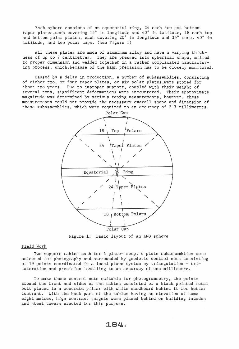
Each sphere consists of an equatorial ring, 24 each top and bottom taper plates,each covering 15° in longitude and 40° in latitude , 18 each top and bottom polar plates , each covering 20° in longitude and 36 6 r esp . 40° in latitude , and two polar caps . (see Figure 1)
All these plates are made of aluminum alloy and have a varying thickness of up to 7 centimetres . They are pressed into spherical shape , milled to proper dimension and welded together in a rather complicated manufacturing process , which , because of the high precision , has to be closely monitored .
Caused by a delay in production , a number of subassemblies , consisting of either two , or four taper plates, or six polar plates,were stored for about two years . Due to improper support, coupled with their weight of several tons , significant deformations were encountered . Their approximate magnitude was determined by various taping measurements, however , these measurements could not provide the necessary overall shape and dimension of these subassemblies , which were required to an accuracy of 2- 3 millimetres .
Polar Cap
\ 1Polars 18
' \ \Tapef ' 24 Plates /
' \ I /
' \ I /
' ' I /
' Equatorial '::K Ring
/
/ I\ / 24/Trper )l~es
I \ '-I
/
/
Figure 1 : Bas~c layout of an LNG sphere
Field Work
Two support tables each for 4 plate- resp. 6 plate subassemblies were selected for photography and surrounded by geodetic control nets consisting of 19 points coordinated in a local plane system by triangulation - trilateration and precision levelling to an accuracy of one millimetre .
To make these control nets suitable for photogrammetry, the points around the front and sides of the tables consisted of a black pointed metal bolt placed in a concrete pillar with white cardboard behind it for better contrast . With the back part of the tables having an elevation of some eight metres, high contrast targets were placed behind on building facades and steel towers erected for this purpose.

All subassemblies were targetted with 100 points at selected locations . Along the edges, double points offset by 100 resp . 200 millimetres normal to them were placed.
To achieve proper contrast to the aluminum, which is matt grey, a white ring was centered around the points edged into the plates . Thus a special template and white spray paint provided a most economical means for targetting.
Photography was semiterrestrial, with the Wild phototheodolite P-31 elevated in a JLG lift to approximately 6 metres for better geometry. The base/object ratio was chosen such as not to ex ceed 1 : 2, which required some convergency for complete stereo-coverage .
The availability of both the JLG lift and a crane for moving the plates determined the time of photography which was frequently not ideal . However, the white ring targetting proved to be efficient for almost all types of sunlight and weather conditions, in spite of occasional heavy reflections .
During photography, special thermometers were attached to the plates to record the plate temperature .
Since many double plates had to be measured,it had been decided to coordinate only their edges by mechanical means with the aid of 35 point pairs placed on concrete pillars surrounding a support table . Each pillar top carried a near horizontal steelplate with two well separated pins . A rectangular square was placed against the pins such that it ' s upright arm touched the edge of the double plate . The offsets along the defined line and orthogonally up to the plate edge were read on the graduations of the square to 0.5 mm . This easy and fast way of coordinating the edges of each double plate however , requires that all the point pairs are coor dinated .
Precision levelling and taping of numerous slope distances between points had been completed when the photogrammetric work for the larger sub assemblies started . The surveying crews had procrastinated with the angular measurements as they did not like the idea of spending weeks on this job . The author's suggestion of using photogrammetry was greeted with enthusiasm, especially since it required only about one hour of fieldwork . This consisted of takingeight s l ightly convergent photographs of the area such that a complete double coverage was obtained . Again , the JLG lift was used to elevate the P- 31 above the area of about 15 x 15 m2 , such tha t a photoscale of approximate l y 1 : 170 was obtained .
Evaluation of Surveying and Photogr~mmetric Data
a) Ground control The elevations of the points were obtained by prec1s1on levelling to an
accuracy of a few tenths of a millimetre , which was much better than required . They were therefore held , and a rigorous planimetric adjustment using the measured directions and distances provided x and y coordinates plus their variances and covariances within a local Cartesian coordinate s ystem . Trigonometric heighting yielded the elevation of unaccessible high points . The accuracy of all points was well within 2 mm .
b) 4- and 6- plate subassemblies The photographs were measured twice independently on the Zeiss PSK
Stereo Comparator . When discrepancies exceeded 3 ~m between the two
185·

measurements,more observations were taken .
Since the photo stations were unknown and different for each photograph, the analytical self calibration program (UNBASC) which treats the basic parameters of interior orientation as well as lens distortion and film deformation as unknown,was utilized.
In this simultaneous approach the coordinates of both camera stations and their orientations are obtained together with the ground coordinates of all object points and their accuracy , utilizing expanded coll i nearity equations in an'bn the job" calibration mode . The mathematical model for this approach has been published, for instance in [3], [5] and [7].
The result of this adjustment was a set of local coordinates for all points , which were obtained well within the required accuracy of 3 millimetres . This accuracy was also verified with check points and check distances read on levelling rods placed randomly on each subassembly prior to photography .
c) Double plate network For reasons stated before, the elevations of all points in the network
were held as determined by precision levelling . By selecting one point as origin plus one direction for orientation, a local coordinate system was defined .
In spite of having some 150 space distances, taped arbitrarily with an accuracy of 0 . 5 mm, it was impossible even to obtain approximate coordinates because of certain points being connected by single distances only . All observations (taped distances reduced to horizontal, and photo coordinates measured on the PSK) were adjusted simultaneously with the program GEBAT (General Bundle Adjustment Triangulation), which accepts geodetic as well as photogrammetric observations . The mathematical model of this program is treated in [ 2], [3] and [4] .
The adjustment resulted in a set of local coordinates of all network points with an accuracy of 0 . 6 mm , which was well within the requirements . The plate edges were coordinated from the coordinate differences between the double points on each pillar , their separation distance,and the observed off- sets by applying simple ratios .
The extrapolation factor of about 2 to reach the plate edge , still satisfied the required accuracy of 3 mm for the plate edge coordinates .
Deformations
Obviously , this set of coordinates means little to an engineer who has to determine milling dimensions for cutting and/or reshaping of the plates . First , all coordinates were corrected for temperature to 60°F (15 . 6°C) using given temperature expansion coefficients .
To obtain sphericity values and thus radial deformations , a best fitting sphere with the design radius was computed using all points and solving for the coordinates of the centre by least squares . The differences between the radial vectors from the centre to all points and the radius directly represent r adial deformations .
In order to obtain tangential deformations along the plate edges , the
:186.

latter was first established by extrapolation using the known offsets . Then all coordinates were transformed into a sphere based system with its origin in the centre, the x /y plane coinciding with the equator plane , and the x/z plane containing one meridian .
For this space rotation, the equator plane had to be defined , otherwise an infinite number of solutions is possible . By holding the parallels at elevations calculated from design radius and - latitudes , this is accomplished . However, radial deformations will then affect the results as the elevation varies with the radius for a given latitude angle .
After eliminating this secondary influence by projecting the points onto the sphere along their radius vectors, the rotated coordinates can easily be interpreted for tangential deformations .
The y- coordinates along the meridian edge which are the residuals after the least squares adjustment,represent directly tangential deviations. A simple rotation around the new z- axis by the longitude angle provides the tangential deviations for the other meridian .
For the parallels, the Z differences to the given value , again representing residuals after the least squares adjustment have to be divided by the cosine of the latitude to result in tangential deviations .
For polar regions the planimetric deviation from the design parallel circle divided by the sine of the latitude gives the tangential deformation (see Figure 2) .
Tangential deviation
R
sin ~
Radial deformation
Figure 2 : Deformations in the parallels
187.
Tangential deviation
~z
cos ~

With the three dimensional coordinates, the object is fully determined and any desired quantities can be subsequently derived as shown for this project.
Although some computational effort is necessary, it has to be pointed out that the actual field work required only a few hours per subassembly plus two days for the geodetic control network observations . This compares very favourably with any conventional surveying procedure, not to mention the 70 point control network where one hour eliminated all angular measurements .
Penstock Survey
Water from a power dam to a turbine flows through a large cylindrical section, called penstock . In order to determine the efficiency of a turbin~ ,
piezometers are installed at certain cross sections of the penstock to measure the flow .
If the cross sectional area of the penstock is known or determined at selected intervals between the piezometer sections , the volume of water passing through during a specific time interval can be computed, which provides a measure of efficiency for a turbine if compared to its output .
The particular penstock section to be measured was 60 feet (18 . 3 m) long . The radius of approximately 14 . 5 feet (4 . 4 m), had to be determined in 4 diameters at 11 cross sections, 6 feet (1 . 8 m) apart, to an accuracy of 0 . 2% , or approximately 17 mm .
There were a number of external conditions which had to be considered as well . The penstock i s inclined by 45° and consists of a steel liner encased in reinforced concrete . Even when the i ntake gates are closed and sealed , there remains a flow of water of about 1/2 metre width . Furthermore, the dewatered period should be kept as short as possible for economic reasons , which, because of virtually no ventilation , means wet and slippery walls . This, together with total darkness and cool temperatures,generates working conditions which are far from being pleasant .
For such a basically two dimensional pr oblem, monophotogrammetry appeared to be most suitable .
Fieldwork
Utilizing equipment , which Dr . Chrzanowski [1] had developed for tunnel profi l ing in mining , a light source rotating in a plane was used to generate a light profile on the interior wall . This profile was photographically recorded using a Hasselblad 500 C camera . In addition, eight control points, covering horizontal and vertical directions , were attached to the profiling equi pment such, that all points were located in the profile plane .
The whole device was mounted on a heavy wooden frame with a 4 m long base , such that when the base was positioned snugly inside the penstock,the axis of rotation of the l i ght source was parallel to the penstock centre line , thus generating a plane normal to it .
The camera was positioned on a second platform below the profile, and oriented such that the profile was imaged symmetrically on the film at a photo scale of approx imately 1 : 200 . Because of the darkness , the shutter
:1..88.

was opened for 1 minute which resulted in a well defined image of profile and control points. For identification purposes, an illuminated number tablet was included as well .
After completion of the photography, the distances between the control points were measured in all combinations with precision tape and micrometer, in order to coordinate them to within 0 .1 mm by trilateration .
In preparation for lens distortion compensation, considered to be necessary for this largest of non-random errors, several levelling rods were fastened against a wall in both horizontal and vertical positions and photographed with the same focus - and £-stop settings as the profiles.
Evaluation
In order to measure similar diameters for each cross-section , a template was drawn on transparent film, consisting of the four required diameter lines plus the control points for orientation purposes . This was superimposed on the profile images. The profiles were then measured on the analytical plotter AP-2C in mono-mode such, that at each measuring location both edges of the profile line were coordinated . Since the light source was not placed in the axis of the cylinder, the profile line had a varying width, the influence of which was eliminated when using the mean of the two points . All these points, together with the control points were measured twice . If the discrepancies exceeded 3 ~m, the measurements were repeated .
The distortion photography was evaluated in the same manner with points being selected such, that their radial distances from the image centre were near those for the control points and the profile circle in the object photography.
A distortion polynomial was computed by least squares with an RMS fit of 2 fjm.
After correcting all photo coordinates for distortion, the control points were used to obtain the parameters for a projective transformation, which was then applied to the profile points .
This was necessary, because the orientation of the image plane with respect to the profile plane was unknown, and the projective transformation was applied just like for any rectification approach .
Once the object coordinates of the profile were computed in the arbitrary control coordinate system, the centre of a best fitting circle was determined by least squares adjustment . Its radius provided the desired cross section radius, while the residuals could be checked for possible systematic deformations occuring in several cross sections . A statistical evaluation revealed that the mean and individual radii were obtained with a standard deviation of 5 mm, which was better than required .
Mechanical check measurements with invar wire and micrometer in one cross section agreed within a few millimetres with the photogrammetrically obtained results.
Concluding Remarks
The two examples discussed in this paper indicate clearly, that
:1.89.
industrial photogramrnetry is not only capable of yielding high accuracies but is usually less time consuming . In the industrial environment, however, it is necessary that various photogramrnetric approaches be considered before method and instrumentation is selected.
To be open minded means also, that for certain aspects of a project, conventional measurements should be elected if they are more economical , even though photogrammetry can do the job . This is illustrated with the double plate survey, where photogrammetry took over the "traditional" control survey, while the object survey was simply accomplished by fast manual measurements .
It is the trademark of a professional to select and use his tools properly, and photogramrnetry is a prime surveying tool, not just in the mapping business .
In closing, I would like to acknowledge with thanks the participation of M. Dennler, S. El Hakim, G. Milliken and L . Szabo in various aspects of the projects .
References
{1] Chrzanowski, A. , Masry, S . "Tunnel Profiling Using a Polaroid Camera" The Canadian Mining and Metallurgical Bulletin~ 1969 .
[2) El Hakim, S. F . "Potentials and Limitations of Photogrammetry for Precision Surveying" Ph .D. Dissertation, University of New Brunswick, Fredericton, N. B. , 1979 .
I 3] El Hakim, S. F . , Moniwa, H. , and Faig , W. "Analytical and Semianalytical Photogrammetric Programs - Theory and User's Manual" Technical Report No . 64, Department of Surveying Engineering, University of New Brunswick , Fredericton, 1979.
[ 4] El Hakim, S . F . , Faig , W. "The General Bundle Adjustment Triangulation (GEBAT) System - Theory and Applications" Presented paper, 14th Congress of the International Society for Photogrammetry, Hamburg, 1980 .
[5) Faig, W. "Calibration of Close- Range Photogrammetric Systems : Mathematical Formulation" Photogrammetric Engineering and Remote Sensing, 1975
[6] Milliken, G.A. Jr. "Photogrammetric Evaluation of Spherical Tank Component Deformations" M.Eng. Report, Department of Surveying Engineering, University of New Brunswick, Fredericton, 1979.
[7] Moniwa, H. "Analytical Photogramrnetric System with Self Calibration and Its Applications" Ph . D. Thesis, University of New Brunswick, Fredericton, N. B. , 1977 .
:1.90.