
1802 Bending Table - greenlee-cdn.ebizcdn.com · 1802 Bending Table Greenlee / A Textron Company 6...
8
INSTRUCTION MANUAL Read and understand all of the instructions and safety information in this manual before operating or servicing this tool. Register this product at www.greenlee.com 99956306 © 2013 Greenlee Textron Inc. IM 887 REV 6 1/13 1802 Bending Table Shown with 884 Bender and 980 Pump
Transcript of 1802 Bending Table - greenlee-cdn.ebizcdn.com · 1802 Bending Table Greenlee / A Textron Company 6...
INSTRUCTION MANUAL
Read and understand all of the instructions and safety information in this manual before operating or servicing this tool.
Register this product at www.greenlee.com99956306 © 2013 Greenlee Textron Inc. IM 887 REV 6 1/13
1802 Bending Table
Shown with 884 Bender and 980 Pump
1802 Bending Table
Greenlee / A Textron Company 4455 Boeing Dr. • Rockford, IL 61109-2988 USA • 815-397-70702
Description
The Greenlee 1802 Bending Table is intended to make the Greenlee 777, 880, 883, 884, and 885 Rigid Conduit Benders easier to use. Loading is faster and easier.
Safety
Safety is essential in the use and maintenance of Greenlee tools and equipment. This instruction manual and any markings on the tool provide information for avoiding hazards and unsafe practices related to the use of this tool. Observe all of the safety information provided.
Purpose of this Manual
This manual is intended to familiarize all personnel with the safe operation and maintenance procedures for the following Greenlee tool:
1802 Bending Table
Keep this manual available to all personnel.
Replacement manuals are available upon request at no charge at www.greenlee.com.
All specifications are nominal and may change as design improvements occur. Greenlee Textron Inc. shall not be liable for damages resulting from misapplication or misuse of its products.
KEEP THIS MANUAL
Table of Contents
Description .................................................................... 2
Safety ............................................................................ 2
Purpose of this Manual ................................................. 2
Important Safety Information ........................................ 3
Setup .......................................................................... 4-6
Illustration ...................................................................... 7
Parts List ....................................................................... 8

1802 Bending Table
Greenlee / A Textron Company 4455 Boeing Dr. • Rockford, IL 61109-2988 USA • 815-397-70703
IMPORTANT SAFETY INFORMATION
SAFETY ALERT SYMBOL
This symbol is used to call your attention to hazards or unsafe practices which could result in an injury or property damage. The signal word, defined below, indicates the severity of the hazard. The message after the signal word provides information for pre-venting or avoiding the hazard.
Immediate hazards which, if not avoided, WILL result in severe injury or death.
Hazards which, if not avoided, COULD result in severe injury or death.
Hazards or unsafe practices which, if not avoided, MAY result in injury or property damage.
Read and understand all of the instructions and safety information in this manual before operating or servicing this tool.
Failure to observe this warning could result in severe injury or death.
Pinch points:
Keep hands away from moving parts.
Failure to observe this warning could result in severe injury or death.
•Do not use as a step or ladder.
•Use only on a hard, flat, level surface.
Failure to observe these warnings could result in severe injury or death.
•Keep bystanders a safe distance from the work area.
•Follow recommended service procedures.
•Use only original equipment or Greenlee specified replacement parts and accessories.
•Use this unit for the manufacturer’s intended purpose only, as described in this manual.
Failure to observe these warnings could result in severe injury or death.
Note: Keep all decals clean and legible, and replace when necessary.
1802 Bending Table
Greenlee / A Textron Company 4455 Boeing Dr. • Rockford, IL 61109-2988 USA • 815-397-70704
Setup
Left End
Right End
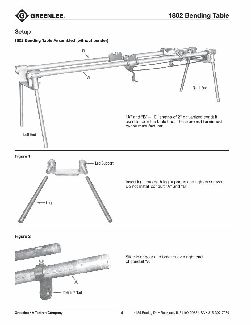
“A” and “B”—10' lengths of 2" galvanized conduit used to form the table bed. These are not furnished by the manufacturer.
Insert legs into both leg supports and tighten screws. Do not install conduit “A” and “B”.
Slide idler gear and bracket over right end of conduit “A”.
1802 Bending Table Assembled (without bender)
Figure 2
Leg
Leg Support
Idler Bracket
Figure 1
1802 Bending Table
Greenlee / A Textron Company 4455 Boeing Dr. • Rockford, IL 61109-2988 USA • 815-397-70705
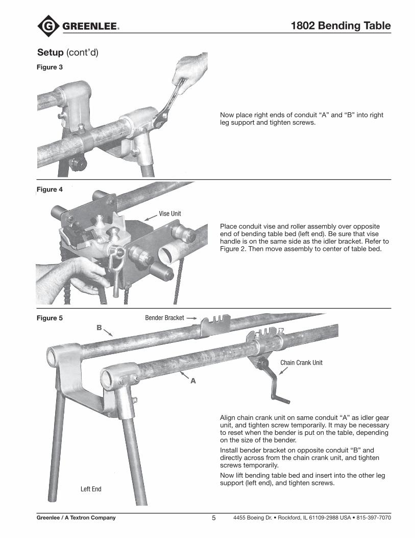
Place conduit vise and roller assembly over opposite end of bending table bed (left end). Be sure that vise handle is on the same side as the idler bracket. Refer to Figure 2. Then move assembly to center of table bed.
Now place right ends of conduit “A” and “B” into right leg support and tighten screws.
Vise Unit
Setup (cont’d)Figure 3
Figure 4
Bender Bracket
Chain Crank Unit
Left End
Align chain crank unit on same conduit “A” as idler gear unit, and tighten screw temporarily. It may be necessary to reset when the bender is put on the table, depending on the size of the bender.
Install bender bracket on opposite conduit “B” and directly across from the chain crank unit, and tighten screws temporarily.
Now lift bending table bed and insert into the other leg support (left end), and tighten screws.
Figure 5
1802 Bending Table
Greenlee / A Textron Company 4455 Boeing Dr. • Rockford, IL 61109-2988 USA • 815-397-70706
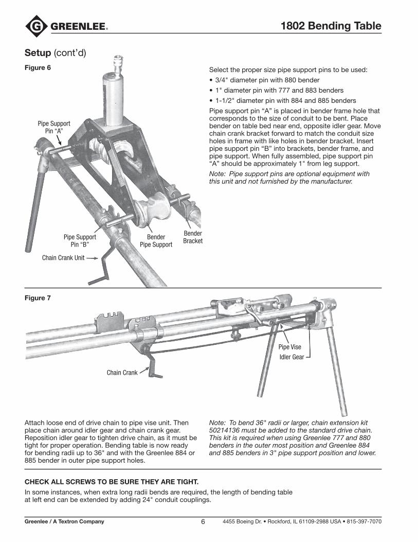
Select the proper size pipe support pins to be used:
•3/4" diameter pin with 880 bender
•1" diameter pin with 777 and 883 benders
•1-1/2" diameter pin with 884 and 885 benders
Pipe support pin “A” is placed in bender frame hole that corresponds to the size of conduit to be bent. Place bender on table bed near end, opposite idler gear. Move chain crank bracket forward to match the conduit size holes in frame with like holes in bender bracket. Insert pipe support pin “B” into brackets, bender frame, and pipe support. When fully assembled, pipe support pin “A” should be approximately 1" from leg support.
Note: Pipe support pins are optional equipment with this unit and not furnished by the manufacturer.
Attach loose end of drive chain to pipe vise unit. Then place chain around idler gear and chain crank gear. Reposition idler gear to tighten drive chain, as it must be tight for proper operation. Bending table is now ready for bending radii up to 36" and with the Greenlee 884 or 885 bender in outer pipe support holes.
Note: To bend 36" radii or larger, chain extension kit 50214136 must be added to the standard drive chain. This kit is required when using Greenlee 777 and 880 benders in the outer most position and Greenlee 884 and 885 benders in 3" pipe support position and lower.
Chain Crank
Pipe Vise
Idler Gear
Pipe SupportPin “A”
Pipe SupportPin “B”
Chain Crank Unit
BenderPipe Support
BenderBracket
Setup (cont’d)Figure 6
Figure 7
CHECK ALL SCREWS TO BE SURE THEY ARE TIGHT.
In some instances, when extra long radii bends are required, the length of bending table at left end can be extended by adding 24" conduit couplings.

1802 Bending Table
Greenlee / A Textron Company 4455 Boeing Dr. • Rockford, IL 61109-2988 USA • 815-397-70707
Illustration
32
33
34
31
3029
2
28
1
2
86
7
2
9
5
10
19
1315
17
2421
22
18
2
1
7
7
5
11413
1440
1440
86
1620
6 8 12
2
3
25–2
7, 3
5
38

1802 Bending Table
Parts List
1 Leg support...........................................2 2 Hex hd. cap screw, 1/2-13 UNC x 1 cad. plated ....................................17 3 Idler bracket ..........................................1 4 Sprocket ...............................................1 5 Skt. hd. shld. screw, 5/8 x 1-1/4 x 1/2-13 ..............................2 6 Lock washer, 1/2 ...................................5 7 Washer, 5/8" bolt x 1-5/16 OD flat ........7 8 Hex nut, 1/2-13 UNC cad. plated .........5 9 Chain crank bracket ..............................1 10 Crank assembly ....................................1 11 50213466 Leg ........................................................4 12 50213490 Saddle assembly ..................................1 13 50247654 Straight roller ........................................4 14 50213512 Spacer, .824 x 1.05 x .38 ......................2 15 Skt. hd. shld. screw, 3/4 x 2-3/4 x 5/8-11 ..............................6 16 Lock nut, 5/8-11 NC-2B .......................6 17 50279947 Pipe vise ...............................................1 18 50213539 Adjusting pad ........................................1 19 Elevating screw assembly.....................1 20 Elevating screw nut ...............................1 21 Hex hd. cap screw, 1/2-13 x 3-1/4 .......2 22 Flat washer std., 1/2 .............................3 24 Hex hd. cap screw, 1/2-13 x 1-1/2 .......1 25 50213628 Chain no. 35 ..........................................1 26 90525590 Offset link w/cotter (no. 35 chain) .........2 27 90517970 Connecting link (no. 35 chain) ..............2 28 Bender bracket .....................................1
Key Part No. Description Qty Key Part No. Description Qty
29 Retaining ring for 880 bender (optional) ...............................................1 30 Retaining ring for 777 and 883 benders (optional) ..........................1 31 Retaining ring for 884 and 885 benders ..........................................1 32 Pipe support pin, 3/4" for 880 bender (optional).......................1 33 Pipe support pin, 1" for 777 and 883 benders (optional) ...................1 34 Pipe support pin, 1-1/2" for 884 and 885 benders ......................1 35 50214136 Chain extension kit ...............................1 37 50232746 Storage box (not shown) .......................1 38 50359053 Large protractor ....................................1 40 50247204 Pipe roller, 2" .........................................2
50215418 Leg support unit (includes 1 of item 1; 6 of item 2) ................................2 50215426 Chain idler unit (includes 1 of items 2-6, 8; 5 of item 7) .......................1 50215434 Crank bracket unit (includes 1 of items 5, 6, 8–10; 2 of items 2, 7) ...........1 50215442 Pipe vise unit (includes 1 of items 12, 17–20, 24, 25; 2 of items 14, 21, 26, 27, 40; 3 of items 6, 8, 22; 6 of items 15, 16; 4 of item 13) .............1 50215450 Bender bracket unit (includes 1 of item 28; 2 of item 2) ..............................1 50213571 Pipe support, 3/4" for 880 bender (includes items 29, 32) (optional) ..........2 50213598 Pipe support, 1" for 777 and 883 benders (includes items 30, 33) (optional) ...............................................2 50213601 Pipe support, 1-1/2" for 884 and 885 benders (includes items 31, 34) .....2
4455 Boeing Drive • Rockford, IL 61109-2988 • USA • 815-397-7070An ISO 9001 Company • Greenlee Textron Inc. is a subsidiary of Textron Inc.
USA Tel: 800-435-0786 Fax: 800-451-2632
Canada Tel: 800-435-0786 Fax: 800-524-2853
International Tel: +1-815-397-7070 Fax: +1-815-397-9247
www.greenlee.com