18 Industrial and Commercial P ower System Protection · 18.1 INTRODUCTION As industrial and...
20
Introduction 18.1 Busbar arrangement 18.2 Discrimination 18.3 HRC fuses 18.4 Industrial circuit breakers 18.5 Protection relays 18.6 Co-ordination problems 18.7 Fault current contribution from induction motors 18.8 Automatic changeover systems 18.9 Voltage and phase reversal protection 18.10 Power factor correction and protection of capacitors 18.11 Examples 18.12 References 18.13 • 18 • Industrial and Commercial Power System Protection
Transcript of 18 Industrial and Commercial P ower System Protection · 18.1 INTRODUCTION As industrial and...

Introduction 18.1
Busbar arrangement 18.2
Discrimination 18.3
HRC fuses 18.4
Industrial circuit breakers 18.5
Protection relays 18.6
Co-ordination problems 18.7
Fault current contributionfrom induction motors 18.8
Automatic changeover systems 18.9
Voltage and phase reversal protection 18.10
Power factor correctionand protection of capacitors 18.11
Examples 18.12
References 18.13
• 1 8 • I n d u s t r i a l a n d C o m m e r c i a lP o w e r S y s t e m P r o t e c t i o n
18.1 INTRODUCTION
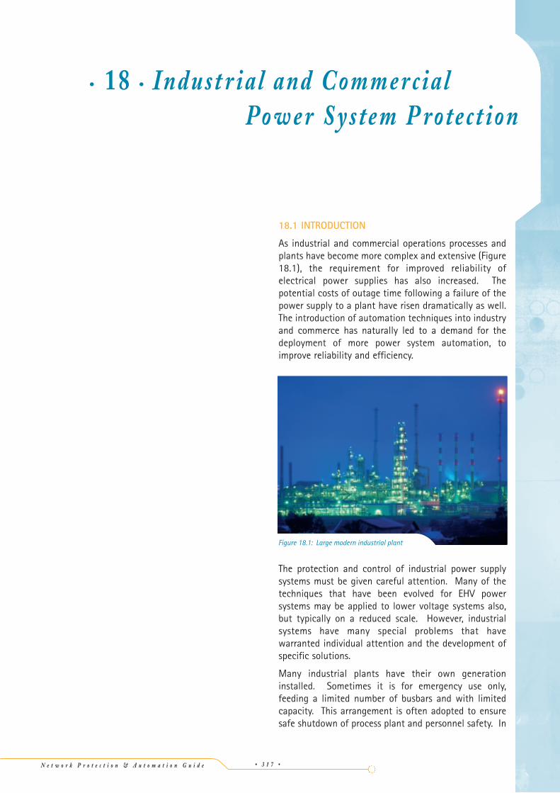
As industrial and commercial operations processes andplants have become more complex and extensive (Figure18.1), the requirement for improved reliability ofelectrical power supplies has also increased. Thepotential costs of outage time following a failure of thepower supply to a plant have risen dramatically as well.The introduction of automation techniques into industryand commerce has naturally led to a demand for thedeployment of more power system automation, toimprove reliability and efficiency.
The protection and control of industrial power supplysystems must be given careful attention. Many of thetechniques that have been evolved for EHV powersystems may be applied to lower voltage systems also,but typically on a reduced scale. However, industrialsystems have many special problems that havewarranted individual attention and the development ofspecific solutions.
Many industrial plants have their own generationinstalled. Sometimes it is for emergency use only,feeding a limited number of busbars and with limitedcapacity. This arrangement is often adopted to ensuresafe shutdown of process plant and personnel safety. In
• 18 • Indu st r ia l an d Comme r cialPow e r Sys te m P rote ct ion
N e t w o r k P r o t e c t i o n & A u t o m a t i o n G u i d e • 3 1 7 •
Figure 18.1: Large modern industrial plant

other plants, the nature of the process allows productionof a substantial quantity of electricity, perhaps allowingexport of any surplus to the public supply system – ateither at sub-transmission or distribution voltage levels.Plants that run generation in parallel with the publicsupply distribution network are often referred to as co-generation or embedded generation. Special protectionarrangements may be demanded for the point ofconnection between the private and public Utility plant(see Chapter 17 for further details).
Industrial systems typically comprise numerous cablefeeders and transformers. Chapter 16 covers theprotection of transformers and Chapters 9/10 theprotection of feeders.
18.2 BUSBAR ARRANGEMENT
The arrangement of the busbar system is obviously veryimportant, and it can be quite complex for some verylarge industrial systems. However, in most systems asingle busbar divided into sections by a bus-sectioncircuit breaker is common, as illustrated in Figure 18.2.Main and standby drives for a particular item of processequipment will be fed from different sections of theswitchboard, or sometimes from different switchboards.
The main power system design criterion is that singleoutages on the electrical network within the plant willnot cause loss of both the main and standby drivessimultaneously. Considering a medium sized industrialsupply system, illustrated in Figure 18.3, in more detail,it will be seen that not only are duplicate supplies andtransformers used, but also certain important loads aresegregated and fed from ‘Essential Services Board(s)’(also known as ‘Emergency’ boards), distributedthroughout the plant. This enables maximum utilisation
of the standby generator facility. A standby generator isusually of the turbo-charged diesel-driven type. Ondetection of loss of incoming supply at any switchboardwith an emergency section, the generator isautomatically started. The appropriate circuit breakerswill close once the generating set is up to speed andrated voltage to restore supply to the Essential Servicessections of the switchboards affected, provided that thenormal incoming supply is absent - for a typical dieselgenerator set, the emergency supply would be availablewithin 10-20 seconds from the start sequence commandbeing issued.
The Essential Services Boards are used to feed equipmentthat is essential for the safe shut down, limited operationor preservation of the plant and for the safety ofpersonnel.
This will cover process drives essential for safe shutdown,venting systems, UPS loads feeding emergency lighting,process control computers, etc. The emergencygenerator may range in size from a single unit rated 20-30kW in a small plant up to several units of 2-10MWrating in a large oil refinery or similar plant. Large
• 18 •
Indu
stri
al a
nd C
omm
erci
al P
ower
Sys
tem
Pro
tect
ion
N e t w o r k P r o t e c t i o n & A u t o m a t i o n G u i d e• 3 1 8 •
NC
NO
Bus section C - Essential suppliesEDG - Emergency generator
A
A
NO B
NC0.4kV
C
NC
NOB C
NO
NO
NO
0.4kV
6kV
0.4kV
33kV
NO
NO
EDG
6kV
110kV
NO
A B
A B
C
*
*
*
*
*
*
* - Two out of three interlock
BA
Figure 18.3: Typical industrial power system
Transformer21
Transformer
interlockmechanical or electrical
HV supply HV supply1 2
2 out of 3
Figure 18.2: Typical switchboardconfiguration for an industrial plant

financial trading institutions may also have standbypower requirements of several MW to maintaincomputer services.
18.3 DISCRIMINATION
Protection equipment works in conjunction withswitchgear. For a typical industrial system, feeders andplant will be protected mainly by circuit breakers ofvarious types and by fused contactors. Circuit breakerswill have their associated overcurrent and earth faultrelays. A contactor may also be equipped with aprotection device (e.g. motor protection), but associatedfuses are provided to break fault currents in excess of thecontactor interrupting capability. The rating of fuses andselection of relay settings is carried out to ensure thatdiscrimination is achieved – i.e. the ability to select andisolate only the faulty part of the system.
18.4 HRC FUSES
The protection device nearest to the actual point ofpower utilisation is most likely to be a fuse or a systemof fuses and it is important that consideration is given tothe correct application of this important device.
The HRC fuse is a key fault clearance device forprotection in industrial and commercial installations,whether mounted in a distribution fuseboard or as partof a contactor or fuse-switch. The latter is regarded as avital part of LV circuit protection, combining safe circuitmaking and breaking with an isolating capabilityachieved in conjunction with the reliable short-circuitprotection of the HRC fuse. Fuses combine thecharacteristics of economy and reliability; factors thatare most important in industrial applications.
HRC fuses remain consistent and stable in their breakingcharacteristics in service without calibration andmaintenance. This is one of the most significant factorsfor maintaining fault clearance discrimination. Lack ofdiscrimination through incorrect fuse grading will resultin unnecessary disconnection of supplies, but if both themajor and minor fuses are HRC devices of proper designand manufacture, this need not endanger personnel orcables associated with the plant.
18.4.1 Fuse Characteristics
The time required for melting the fusible elementdepends on the magnitude of current. This time is knownas the ‘pre-arcing’ time of the fuse. Vaporisation of theelement occurs on melting and there is fusion betweenthe vapour and the filling powder leading to rapid arcextinction.
Fuses have a valuable characteristic known as ‘cut-off’,
illustrated in Figure 18.4. When an unprotected circuitis subjected to a short circuit fault, the r.m.s. currentrises towards a ‘prospective’ (or maximum) value. Thefuse usually interrupts the short circuit current before itcan reach the prospective value, in the first quarter tohalf cycle of the short circuit. The rising current isinterrupted by the melting of the fusible element,subsequently dying away dying away to zero during thearcing period.
Since the electromagnetic forces on busbars andconnections carrying short circuit current are related to thesquare of the current, it will be appreciated that ‘cut-off’significantly reduces the mechanical forces produced bythe fault current and which may distort the busbars andconnections if not correctly rated. A typical example of‘cut-off’ current characteristics is illustrated in Figure 18.5.
• 18 •In
dust
rial
and
Com
mer
cial
Pow
er S
yste
m P
rote
ctio
n
N e t w o r k P r o t e c t i o n & A u t o m a t i o n G u i d e • 3 1 9 •
1250A710A500A400A200A125A80A50A35A25A16A
6A
2A
800A630A
315A
0.1 1.0 10 100 500
0.1
1.0
10
100
1000
Prospective current (kA r.m.s. symmetrical)
Cut
off c
urre
nt (p
eak
kA)
Figure 18.5: Typical fuse cut-off currentcharacteristics
feature
IpIpI
1 Cycle
Arcingtime
Pre-arcing time
Total clearance time
Current trace
Curve of asymmetricalprospective short-circuitcurrent
TimeStart of
short-circuit
Figure 18.4: HRC fuse cut-off feature

It is possible to use this characteristic during the designstage of a project to utilise equipment with a lower faultwithstand rating downstream of the fuse, than would bethe case if ‘cut-off’ was ignored. This may save on costs,but appropriate documentation and maintenancecontrols are required to ensure that only replacementfuses of very similar characteristics are used throughoutthe lifetime of the plant concerned – otherwise a safetyhazard may arise.
18.4.2 Discrimination Between Fuses
Fuses are often connected in series electrically and it isessential that they should be able to discriminate witheach other at all current levels. Discrimination isobtained when the larger (‘major’) fuse remainsunaffected by fault currents that are cleared by thesmaller (‘minor’) fuse.
The fuse operating time can be considered in two parts:
i. the time taken for fault current to melt theelement, known as the ‘pre-arcing time’
ii. the time taken by the arc produced inside the fuseto extinguish and isolate the circuit, known as the‘arcing time’
The total energy dissipated in a fuse during its operationconsists of ‘pre-arcing energy’ and ‘arc energy’. Thevalues are usually expressed in terms of I2t, where I is thecurrent passing through the fuse and t is the time inseconds. Expressing the quantities in this mannerprovides an assessment of the heating effect that thefuse imposes on associated equipment during itsoperation under fault conditions.
To obtain positive discrimination between fuses, the totalI2t value of the minor fuse must not exceed the pre-arcing I2t value of the major fuse. In practice, this meansthat the major fuse will have to have a ratingsignificantly higher than that of the minor fuse, and thismay give rise to problems of discrimination. Typically,the major fuse must have a rating of at least 160% ofthe minor fuse for discrimination to be obtained.
18.4.3 Protection of Cables by Fuses
PVC cable is allowed to be loaded to its full nominalrating only if it has ‘close excess current protection’. Thisdegree of protection can be given by means of a fuse linkhaving a ‘fusing factor’ not exceeding 1.5, where:
Fusing factor =
Cables constructed using other insulating materials (e.g.paper, XLPE) have no special requirements in this respect.
Minimum Fusing CurrentCurrent Rating
18.4.4 Effect of Ambient Temperature
High ambient temperatures can influence the capabilityof HRC fuses. Most fuses are suitable for use in ambienttemperatures up to 35°C, but for some fuse ratings,derating may be necessary at higher ambienttemperatures. Manufacturers' published literatureshould be consulted for the de-rating factor to beapplied.
18.4.5 Protection of Motors
The manufacturers' literature should also be consultedwhen fuses are to be applied to motor circuits. In thisapplication, the fuse provides short circuit protection butmust be selected to withstand the starting current(possibly up to 8 times full load current), and also carrythe normal full load current continuously withoutdeterioration. Tables of recommended fuse sizes for both‘direct on line’ and ‘assisted start’ motor applications areusually given. Examples of protection using fuses aregiven in Section 18.12.1.
18.5 INDUSTRIAL CIRCUIT BREAKERS
Some parts of an industrial power system are mosteffectively protected by HRC fuses, but the replacementof blown fuse links can be particularly inconvenient inothers. In these locations, circuit breakers are usedinstead, the requirement being for the breaker tointerrupt the maximum possible fault currentsuccessfully without damage to itself. In addition tofault current interruption, the breaker must quicklydisperse the resulting ionised gas away from the breakercontacts, to prevent re-striking of the arc, and away fromother live parts of equipment to prevent breakdown. Thebreaker, its cable or busbar connections, and the breakerhousing, must all be constructed to withstand themechanical forces resulting from the magnetic fields andinternal arc gas pressure produced by the highest levelsof fault current to be encountered.
The types of circuit breaker most frequently encounteredin industrial system are described in the followingsections.
18.5.1 Miniature Circuit Breakers (MCB’s)
MCB’s are small circuit breakers, both in physical size butmore importantly, in ratings. The basic single pole unit isa small, manually closed, electrically or manually openedswitch housed in a moulded plastic casing. They aresuitable for use on 230V a.c. single-phase/400V a.c.three-phase systems and for d.c. auxiliary supplysystems, with current ratings of up to 125A. Containedwithin each unit is a thermal element, in which a bimetal
• 18 •
Indu
stri
al a
nd C
omm
erci
al P
ower
Sys
tem
Pro
tect
ion
N e t w o r k P r o t e c t i o n & A u t o m a t i o n G u i d e• 3 2 0 •

strip will trip the switch when excessive current passesthrough it. This element operates with a predeterminedinverse-time/current characteristic. Higher currents,typically those exceeding 3-10 times rated current, tripthe circuit breaker without intentional delay byactuating a magnetic trip overcurrent element. Theoperating time characteristics of MCB’s are notadjustable. European Standard EN 60898-2 defines theinstantaneous trip characteristics, while themanufacturer can define the inverse time thermal tripcharacteristic. Therefore, a typical tripping characteristicdoes not exist. The maximum a.c. breaking currentpermitted by the standard is 25kA.
Single-pole units may be coupled mechanically in groupsto form 2, 3 or 4 pole units, when required, by assemblyon to a rail in a distribution board. The available ratingsmake MCB's suitable for industrial, commercial ordomestic applications, for protecting equipment such ascables, lighting and heating circuits, and also for thecontrol and protection of low power motor circuits. Theymay be used instead of fuses on individual circuits, andthey are usually ‘backed-up’ by a device of higher faultinterrupting capacity.
Various accessory units, such as isolators, timers, andundervoltage or shunt trip release units may becombined with an MCB to suit the particular circuit to becontrolled and protected. When personnel or fireprotection is required, a residual current device (RCD)may be combined with the MCB. The RCD contains aminiature core balance current transformer thatembraces all of the phase and neutral conductors toprovide sensitivity to earth faults within a typical rangeof 0.05% to 1.5% of rated current, dependent on theRCD selected. The core balance CT energises a commonmagnetic trip actuator for the MCB assembly.
It is also possible to obtain current-limiting MCB’s.These types open prior to the prospective fault currentbeing reached, and therefore have similar properties toHRC fuses. It is claimed that the extra initial cost isoutweighed by lifetime savings in replacement costsafter a fault has occurred, plus the advantage ofproviding improved protection against electric shock ifan RCD is used. As a result of the increased safetyprovided by MCB’s fitted with an RCD device, they aretending to replace fuses, especially in new installations.
18.5.2 Moulded Case Circuit Breakers (MCCB’s)
These circuit breakers are broadly similar to MCB’s buthave the following important differences:
a. the maximum ratings are higher, with voltageratings up to 1000V a.c./1200V d.c. Current ratingsof 2.5kA continuous/180kA r.m.s break are possible,dependent upon power factor
b. the breakers are larger, commensurate with thelevel of ratings. Although available as single,double or triple pole units, the multiple pole unitshave a common housing for all the poles. Wherefitted, the switch for the neutral circuit is usually aseparate device, coupled to the multi-pole MCCB
c. the operating levels of the magnetic and thermalprotection elements may be adjustable, particularlyin the larger MCCB’s
d. because of their higher ratings, MCCB’s are usuallypositioned in the power distribution system nearerto the power source than the MCB’s
e. the appropriate European specification is EN60947-2
Care must be taken in the short-circuit ratings ofMCCB’s. MCCB’s are given two breaking capacities, thehigher of which is its ultimate breaking capacity. Thesignificance of this is that after breaking such a current,the MCCB may not be fit for continued use. The lower,or service, short circuit breaking capacity permitscontinued use without further detailed examination ofthe device. The standard permits a service breakingcapacity of as little as 25% of the ultimate breakingcapacity. While there is no objection to use of MCCB’sto break short-circuit currents between the service andultimate values, the inspection required after such a tripreduces the usefulness of the device in suchcircumstances. It is also clearly difficult to determine ifthe magnitude of the fault current was in excess of theservice rating.
The time-delay characteristics of the magnetic orthermal timed trip, together with the necessity for, orsize of, a back-up device varies with make and size ofbreaker. Some MCCB’s are fitted with microprocessor-controlled programmable trip characteristics offering awide range of such characteristics. Time–delayedovercurrent characteristics may not be the same as thestandard characteristics for dependent-time protectionstated in IEC 60255-3. Hence, discrimination with otherprotection must be considered carefully. There can beproblems where two or more MCB’s or MCCB’s areelectrically in series, as obtaining selectivity betweenthem may be difficult. There may be a requirement thatthe major device should have a rating of k times theminor device to allow discrimination, in a similar mannerto fuses – the manufacturer should be consulted as tovalue of k. Careful examination of manufacturers’literature is always required at the design stage todetermine any such limitations that may be imposed byparticular makes and types of MCCB’s. An example ofco-ordination between MCCB’s, fuses and relays is givenin Section 18.12.2.
• 18 •In
dust
rial
and
Com
mer
cial
Pow
er S
yste
m P
rote
ctio
n
N e t w o r k P r o t e c t i o n & A u t o m a t i o n G u i d e • 3 2 1 •

18.5.3 Air Circuit Breakers (ACB’s)
Air circuit breakers are frequently encountered onindustrial systems rated at 3.3kV and below. Modern LVACB’s are available in current ratings of up to 6.3kA withmaximum breaking capacities in the range of 85kA-120kA r.m.s., depending on system voltage.
This type of breaker operates on the principle that the arcproduced when the main contacts open is controlled bydirecting it into an arc chute. Here, the arc resistance isincreased and hence the current reduced to the pointwhere the circuit voltage cannot maintain the arc andthe current reduces to zero. To assist in the quenchingof low current arcs, an air cylinder may be fitted to eachpole to direct a blast of air across the contact faces asthe breaker opens, so reducing contact erosion.
Air circuit breakers for industrial use are usuallywithdrawable and are constructed with a flush frontplate making them ideal for inclusion together with fuseswitches and MCB’s/MCCB’s in modular multi-tierdistribution switchboards, so maximising the number ofcircuits within a given floor area.
Older types using a manual or dependent manual closingmechanism are regarded as being a safety hazard. Thisarises under conditions of closing the CB when a faultexists on the circuit being controlled. During the close-trip operation, there is a danger of egress of the arc fromthe casing of the CB, with a consequent risk of injury tothe operator. Such types may be required to be replacedwith modern equivalents.
ACB’s are normally fitted with integral overcurrentprotection, thus avoiding the need for separateprotection devices. However, the operating timecharacteristics of the integral protection are oftendesigned to make discrimination withMCB’s/MCCB’s/fuses easier and so they may not be inaccordance with the standard dependent timecharacteristics given in IEC 60255-3. Therefore,problems in co-ordination with discrete protection relaysmay still arise, but modern numerical relays have moreflexible characteristics to alleviate such difficulties.ACB’s will also have facilities for accepting an externaltrip signal, and this can be used in conjunction with anexternal relay if desired. Figure 18.6 illustrates thetypical tripping characteristics available.
18.5.4 Oil Circuit Breakers (OCB’s)
Oil circuit breakers have been very popular for manyyears for industrial supply systems at voltages of 3.3kVand above. They are found in both ‘bulk oil’ and‘minimum oil’ types, the only significant difference beingthe volume of oil in the tank.
In this type of breaker, the main contacts are housed inan oil-filled tank, with the oil acting as the both theinsulation and the arc-quenching medium. The arcproduced during contact separation under faultconditions causes dissociation of the hydrocarboninsulating oil into hydrogen and carbon. The hydrogenextinguishes the arc. The carbon produced mixes withthe oil. As the carbon is conductive, the oil must bechanged after a prescribed number of fault clearances,when the degree of contamination reaches anunacceptable level.
Because of the fire risk involved with oil, precautionssuch as the construction of fire/blast walls may have tobe taken when OCB’s are installed.
18.5.5 Vacuum Circuit Breakers (VCB’s)
In recent years, this type of circuit breaker, along withCB’s using SF6, has replaced OCB’s for new installationsin industrial/commercial systems at voltages of 3.3kVand above.
Compared with oil circuit breakers, vacuum breakershave no fire risk and they have high reliability with longmaintenance free periods. A variation is the vacuumcontactor with HRC fuses, used in HV motor starterapplications.
18.5.6 SF6 Circuit Breakers
In some countries, circuit breakers using SF6 gas as thearc-quenching medium are preferred to VCB’s as the
• 18 •
Indu
stri
al a
nd C
omm
erci
al P
ower
Sys
tem
Pro
tect
ion
N e t w o r k P r o t e c t i o n & A u t o m a t i o n G u i d e• 3 2 2 •
0.011 10
Current (multiple of setting)
Tim
e (s
)
Inverse
Very Inverse
Ultra Inverse
Short Circuit
0.1
1
10
100
1000
20
Figure 18.6: Typical tripping characteristicsof an ACB
• 18 •In
dust
rial
and
Com
mer
cial
Pow
er S
yste
m P
rote
ctio
n
N e t w o r k P r o t e c t i o n & A u t o m a t i o n G u i d e • 3 2 3 •
A B C N
A B C N
B CA
A B C
CBA
A B C
(h)
(g)
(f)
(e)
(d)
(c)
(b)
(a)
CTconnections
Residual-current
elements
SystemPhaseelements
Type offault
Notes
Ph. - E
3Ph. 4w
3Ph. 4w
3Ph. 4w
3Ph. 3w
3Ph. 3w
3Ph. 3w
3Ph. 3w Ph. - Ph. Petersen coil andunearthed systems.
3Ph. 3wor
3Ph. 4w
Earth-fault settingsmay be less than full
load
Earth-fault settingsmay be less than full
load
Earth-fault settingsmay be less than full
load
(i) Ph. - Ph.(ii) Ph. - E(iii) Ph. - N
(i) Ph. - Ph.(ii) Ph. - E(iii) Ph. - N
(i) Ph. - Ph.(ii) Ph. - E*(iii) Ph. - N
(i) Ph. - Ph.(ii) Ph. - E*
(i) Ph. - Ph.(ii) Ph. - E
(i) Ph. - Ph.(ii) Ph. - E
Earth-fault settingsmay be less than full
load, but must begreater than largest
Ph. - N load
Phase elements mustbe in same phases at
all stations.Earth-fault settingsmay be less than full
load
* Earth-fault protectiononly if earth-faultcurrent is not lessthan twice primary
operatingcurrent
Ph. = phase ; w = wire ; E = earth ; N = neutral
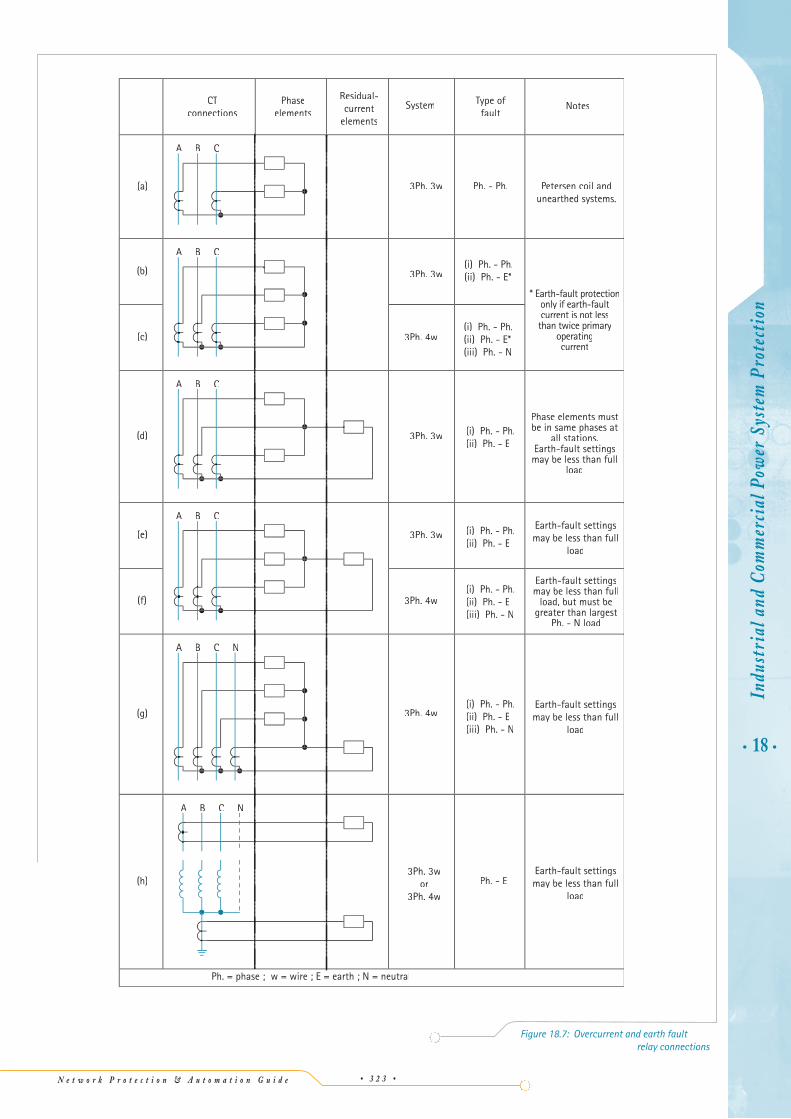
Figure 18.7: Overcurrent and earth faultrelay connections

replacement for air- and oil-insulated CB’s. Somemodern types of switchgear cubicles enable the use ofeither VCB’s or SF6-insulated CB’s according to customerrequirements. Ratings of up to 31.5kA r.m.s. fault breakat 36kV and 40kA at 24kV are typical. SF6-insulated CB’salso have advantages of reliability and maintenanceintervals compared to air- or oil-insulated CB’s and areof similar size to VCB’s for the same rating.
18.6 PROTECTION RELAYS
When the circuit breaker itself does not have integralprotection, then a suitable external relay will have to beprovided. For an industrial system, the most commonprotection relays are time-delayed overcurrent and earthfault relays. Chapter 9 provides details of the applicationof overcurrent relays.
Traditionally, for three wire systems, overcurrent relayshave often been applied to two phases only for relayelement economy. Even with modern multi-elementrelay designs, economy is still a consideration in terms ofthe number of analogue current inputs that have to beprovided. Two overcurrent elements will detect anyinterphase fault, so it is conventional to apply twoelements on the same phases at all relay locations. Thephase CT residual current connections for an earth faultrelay element are unaffected by this convention. Figure18.7 illustrates the possible relay connections andlimitations on settings.
18.7 CO-ORDINATION PROBLEMS
There are a number of problems that commonly occur inindustrial and commercial networks that are covered inthe following sections.
18.7.1.1 Earth Fault protectionwith residually-connected CT’s
For four-wire systems, the residual connection of threephase CT’s to an earth fault relay element will offer earthfault protection, but the earth fault relay element mustbe set above the highest single-phase load current toavoid nuisance tripping. Harmonic currents (which maysum in the neutral conductor) may also result in spurioustripping. The earth fault relay element will also respondto a phase-neutral fault for the phase that is not coveredby an overcurrent element where only two overcurrentelements are applied. Where it is required that the earthfault protection should respond only to earth faultcurrent, the protection element must be residuallyconnected to three phase CT’s and to a neutral CT or toa core-balance CT. In this case, overcurrent protectionmust be applied to all three phases to ensure that allphase-neutral faults will be detected by overcurrentprotection. Placing a CT in the neutral earthing
connection to drive an earth fault relay provides earthfault protection at the source of supply for a 4-wiresystem. If the neutral CT is omitted, neutral current isseen by the relay as earth fault current and the relaysetting would have to be increased to prevent trippingunder normal load conditions.
When an earth fault relay is driven from residuallyconnected CT’s, the relay current and time settings mustbe such that that the protection will be stable during thepassage of transient CT spill current through the relay.Such spill current can flow in the event of transient,asymmetric CT saturation during the passage of offsetfault current, inrush current or motor starting current.The risk of such nuisance tripping is greater with thedeployment of low impedance electronic relays ratherthan electromechanical earth fault relays whichpresented significant relay circuit impedance. Energisinga relay from a core balance type CT generally enablesmore sensitive settings to be obtained without the risk ofnuisance tripping with residually connected phase CT’s.When this method is applied to a four-wire system, it isessential that both the phase and neutral conductors arepassed through the core balance CT aperture. For a 3-wire system, care must be taken with the arrangement ofthe cable sheath, otherwise cable faults involving thesheath may not result in relay operation (Figure 18.8).
• 18 •
Indu
stri
al a
nd C
omm
erci
al P
ower
Sys
tem
Pro
tect
ion
N e t w o r k P r o t e c t i o n & A u t o m a t i o n G u i d e• 3 2 4 •
Cable gland /sheathground connection
Cable gland
Cable gland /sheath
Cable box
Relay does not operate
(a) Incorrect
Relay operates
(b) Correct
I >I
I >I
I >I
Figure 18.8: CBCT connection forfour-wire system

18.7.2 Four-Wire Dual-Fed Substations
The co-ordination of earth fault relays protecting four-wire systems requires special consideration in the case oflow voltage, dual-fed installations. Horcher [18.1] hassuggested various methods of achieving optimum co-ordination. Problems in achieving optimum protectionfor common configurations are described below.
18.7.2.1 Use of 3-pole CB’s
When both neutrals are earthed at the transformers andall circuit breakers are of the 3-pole type, the neutralbusbar in the switchgear creates a double neutral toearth connection, as shown in Figure 18.9. In the eventof an uncleared feeder earth fault or busbar earth fault,with both the incoming supply breakers closed and thebus section breaker open, the earth fault current willdivide between the two earth connections. Earth faultrelay RE2 may operate, tripping the supply to the healthysection of the switchboard as well as relay RE1 trippingthe supply to the faulted section.
If only one incoming supply breaker is closed, the earthfault relay on the energised side will see only aproportion of the fault current flowing in the neutralbusbar. This not only significantly increases the relayoperating time but also reduces its sensitivity to low-level earth faults.
The solution to this problem is to utilise 4-pole CB’s thatswitch the neutral as well as the three phases. Thenthere is only a single earth fault path and relay operationis not compromised.
18.7.2.2 Use of single earth electrode
A configuration sometimes adopted with four-wire dual-fed substations where only a 3-pole bus section CB isused is to use a single earth electrode connected to themid-point of the neutral busbar in the switchgear, asshown in Figure 18.10. When operating with bothincoming main circuit breakers and the bus sectionbreaker closed, the bus section breaker must be openedfirst should an earth fault occur, in order to achievediscrimination. The co-ordination time between theearth fault relays RF and RE should be established atfault level F2 for a substation with both incoming supplybreakers and bus section breaker closed.
When the substation is operated with the bus sectionswitch closed and either one or both of the incomingsupply breakers closed, it is possible for unbalancedneutral busbar load current caused by single phaseloading to operate relay RS1 and/or RS2 and inadvertentlytrip the incoming breaker. Interlocking the trip circuit ofeach RS relay with normally closed auxiliary contacts onthe bus section breaker can prevent this.
However, should an earth fault occur on one side of thebusbar when relays RS are already operated, it is possiblefor a contact race to occur. When the bus sectionbreaker opens, its break contact may close before the RSrelay trip contact on the healthy side can open (reset).Raising the pick-up level of relays RS1 and RS2 above themaximum unbalanced neutral current may prevent thetripping of both supply breakers in this case. However,the best solution is to use 4-pole circuit breakers, and
• 18 •In
dust
rial
and
Com
mer
cial
Pow
er S
yste
m P
rote
ctio
n
N e t w o r k P r o t e c t i o n & A u t o m a t i o n G u i d e • 3 2 5 •
Supply 1
RS1
F1
F2F
RS2
E
RF
Supply 2
I >I I I I
I >I I I I
I >I I I I I >I I I I
N
Figure 18.10: Dual fed four-wire systems:use of single point neutral earthing
RE1
IFI
IFI
IFI /2F/2 IFI /2F/2
IFIF/2F/2
IFI /2F/2
RE2
Neutral busbarSupply 1 Supply 2
Bus section CB
Figure 18.9: Dual fed four-wire systems:use of 3-pole CB’s

independently earth both sides of the busbar.
If, during a busbar earth fault or uncleared feeder earthfault, the bus section breaker fails to open whenrequired, the interlocking break auxiliary contact willalso be inoperative. This will prevent relays RS1 and RS2from operating and providing back-up protection, withthe result that the fault must be cleared eventually byslower phase overcurrent relays. An alternative methodof obtaining back-up protection could be to connect asecond relay R’E, in series with relay RE, having anoperation time set longer than that of relays RS1 andRS2. But since the additional relay must be arranged totrip both of the incoming supply breakers, back-upprotection would be obtained but busbar selectivitywould be lost.
An example of protection of a typical dual-fedswitchboard is given in Section 18.12.3.
18.8 FAULT CURRENT CONTRIBUTIONFROM INDUCTION MOTORS
When an industrial system contains motor loads, themotors will contribute fault current for a short time.They contribute to the total fault current via thefollowing mechanism.
When an induction motor is running, a flux, generated bythe stator winding, rotates at synchronous speed andinteracts with the rotor. If a large reduction in the statorvoltage occurs for any reason, the flux in the motorcannot change instantaneously and the mechanicalinertia of the machine will tend to inhibit speedreduction over the first few cycles of fault duration. Thetrapped flux in the rotor generates a stator voltage equalinitially to the back e.m.f. induced in the stator beforethe fault and decaying according to the X/R ratio of theassociated flux and current paths. The induction motortherefore acts as a generator resulting in a contributionof current having both a.c. and d.c. components decayingexponentially. Typical 50Hz motor a.c. time constants liein the range 10ms-60ms for LV motors and 60-200ms forHV motors. This motor contribution has often beenneglected in the calculation of fault levels.
Industrial systems usually contain a large component ofmotor load, so this approach is incorrect. Thecontribution from motors to the total fault current maywell be a significant fraction of the total in systemshaving a large component of motor load. Standardsrelating to fault level calculations, such as IEC 60909,require the effect of motor contribution to be includedwhere appropriate. They detail the conditions underwhich this should be done, and the calculation methodto be used. Guidance is provided on typical motor faultcurrent contribution for both HV and LV motors if therequired data is not known. Therefore, it is now
relatively easy, using appropriate calculation software, todetermine the magnitude and duration of the motorcontribution, so enabling a more accurate assessment ofthe fault level for:
a. discrimination in relay co-ordination
b. determination of the required switchgear/busbarfault rating
For protection calculations, motor fault levelcontribution is not an issue that is generally is important.In industrial networks, fault clearance time is oftenassumed to occur at 5 cycles after fault occurrence, andat this time, the motor fault level contribution is muchless than just after fault occurrence. In rare cases, it mayhave to be taken into consideration for correct timegrading for through-fault protection considerations, andin the calculation of peak voltage for high-impedancedifferential protection schemes.
It is more important to take motor contribution intoaccount when considering the fault rating of equipment(busbars, cables, switchgear, etc.). In general, the initiala.c. component of current from a motor at the instant offault is of similar magnitude to the direct-on-linestarting current of the motor. For LV motors, 5xFLC isoften assumed as the typical fault current contribution(after taking into account the effect of motor cableimpedance), with 5.5xFLC for HV motors, unless it isknown that low starting current HV motors are used. Itis also accepted that similar motors connected to abusbar can be lumped together as one equivalent motor.In doing so, motor rated speed may need to be taken intoconsideration, as 2 or 4 pole motors have a longer faultcurrent decay than motors with a greater number ofpoles. The kVA rating of the single equivalent motor istaken as the sum of the kVA ratings of the individualmotors considered. It is still possible for motorcontribution to be neglected in cases where the motorload on a busbar is small in comparison to the total load(again IEC 60909 provides guidance in this respect).However, large LV motor loads and all HV motors shouldbe considered when calculating fault levels.
18.9 AUTOMATIC CHANGEOVER SYSTEMS
Induction motors are often used to drive critical loads. Insome industrial applications, such as those involving thepumping of fluids and gases, this has led to the need fora power supply control scheme in which motor and otherloads are transferred automatically on loss of the normalsupply to an alternative supply. A quick changeover,enabling the motor load to be re-accelerated, reducesthe possibility of a process trip occurring. Such schemesare commonly applied for large generating units totransfer unit loads from the unit transformer to thestation supply/start-up transformer.
• 18 •
Indu
stri
al a
nd C
omm
erci
al P
ower
Sys
tem
Pro
tect
ion
N e t w o r k P r o t e c t i o n & A u t o m a t i o n G u i d e• 3 2 6 •

When the normal supply fails, induction motors thatremain connected to the busbar slow down and thetrapped rotor flux generates a residual voltage thatdecays exponentially. All motors connected to a busbarwill tend to decelerate at the same rate when the supplyis lost if they remain connected to the busbar. This isbecause the motors will exchange energy betweenthemselves, so that they tend to stay ‘synchronised’ toeach other. As a result, the residual voltages of all themotors decay at nearly the same rate. The magnitude ofthis voltage and its phase displacement with respect tothe healthy alternative supply voltage is a function oftime and the speed of the motors. The angulardisplacement between the residual motor voltage andthe incoming voltage will be 180° at some instant. If thehealthy alternative supply is switched on to motorswhich are running down under these conditions, veryhigh inrush currents may result, producing stresseswhich could be of sufficient magnitude to causemechanical damage, as well as a severe dip in thealternative supply voltage.
Two methods of automatic transfer are used:
a. in-phase transfer system
b. residual voltage system
The in-phase transfer method is illustrated in Figure18.11(a). Normal and standby feeders from the samepower source are used.
Phase angle measurement is used to sense the relativephase angle between the standby feeder voltage and themotor busbar voltage. When the voltages areapproximately in phase, or just prior to this conditionthrough prediction, a high-speed circuit breaker is usedto complete the transfer. This method is restricted tolarge high inertia drives where the gradual run downcharacteristic upon loss of normal feeder supply can bepredicted accurately.
Figure 18.11(b) illustrates the residual voltage method,which is more common, especially in the petrochemicalindustry.
Two feeders are used, supplying two busbar sectionsconnected by a normally open bus section breaker. Eachfeeder is capable of carrying the total busbar load. Eachbus section voltage is monitored and loss of supply oneither section causes the relevant incomer CB to open.Provided there are no protection operations to indicatethe presence of a busbar fault, the bus section breaker isclosed automatically to restore the supply to theunpowered section of busbar after the residual voltagegenerated by the motors running down on that sectionhas fallen to a an acceptable level. This is between 25%and 40%, of nominal voltage, dependent on thecharacteristics of the power system. The choice ofresidual voltage setting will influence the re-acceleration current after the bus section breaker closes.For example, a setting of 25% may be expected to resultin an inrush current of around 125% of the startingcurrent at full voltage. Alternatively, a time delay couldbe used as a substitute for residual voltagemeasurement, which would be set with knowledge of theplant to ensure that the residual voltage would havedecayed sufficiently before transfer is initiated.
The protection relay settings for the switchboard musttake account of the total load current and the voltagedip during the re-acceleration period in order to avoidspurious tripping during this time. This time can beseveral seconds where large inertia HV drives areinvolved.
18.10 VOLTAGE AND PHASE REVERSAL PROTECTION
Voltage relays have been widely used in industrial powersupply systems. The principle purposes are to detectundervoltage and/or overvoltage conditions atswitchboards to disconnect supplies before damage canbe caused from these conditions or to provideinterlocking checks. Prolonged overvoltage may causedamage to voltage-sensitive equipment (e.g. electronics),while undervoltage may cause excessive current to be
• 18 •In
dust
rial
and
Com
mer
cial
Pow
er S
yste
m P
rote
ctio
n
N e t w o r k P r o t e c t i o n & A u t o m a t i o n G u i d e • 3 2 7 •
(a) In phase transfer method
M
High speedCB
Phaseanglerelay
Preferredfeeder
Standbyfeeder
(b) Residual voltage method
M
Feeder No.1 Feeder No.2
M M M
ϕ <
Ursd UU < Ursd UU <
Figure 18.11: Auto-transfer systems

drawn by motor loads. Motors are provided with thermaloverload protection to prevent damage with excessivecurrent, but undervoltage protection is commonlyapplied to disconnect motors after a prolonged voltagedip. With a voltage dip caused by a source system fault,a group of motors could decelerate to such a degree thattheir aggregate re-acceleration currents might keep therecovery voltage depressed to a level where the machinesmight stall. Modern numerical motor protection relaystypically incorporate voltage protection functions, thusremoving the need for discrete undervoltage relays forthis purpose (see Chapter 19). Older installations maystill utilise discrete undervoltage relays, but the settingcriteria remain the same.
Reverse phase sequence voltage protection should beapplied where it may be dangerous for a motor to bestarted with rotation in the opposite direction to thatintended. Incorrect rotation due to reverse phasesequence might be set up following some error afterpower system maintenance or repairs, e.g. to a supplycable. Older motor control boards might have been fittedwith discrete relays to detect this condition. Modernmotor protection relays may incorporate this function. Ifreverse phase sequence is detected, motor starting can beblocked. If reverse phase sequence voltage protection isnot provided, the high-set negative phase sequencecurrent protection in the relay would quickly detect thecondition once the starting device is closed – but initialreverse rotation of the motor could not be prevented.
18.11 POWER FACTOR CORRECTIONAND PROTECTION OF CAPACITORS
Loads such as induction motors draw significant reactivepower from the supply system, and a poor overall powerfactor may result. The flow of reactive power increasesthe voltage-drops through series reactances such astransformers and reactors, it uses up some of the currentcarrying capacity of power system plant and it increasesthe resistive losses in the power system.
To offset the losses and restrictions in plant capacitythey incur and to assist with voltage regulation, Utilitiesusually apply tariff penalties to large industrial orcommercial customers for running their plant atexcessively low power factor. The customer is therebyinduced to improve the power factor of his system and itmay be cost-effective to install fixed or variable powerfactor correction equipment to raise or regulate theplant power factor to an acceptable level.
Shunt capacitors are often used to improve power factor.The basis for compensation is illustrated in Figure 18.12,where ∠ϕ1 represents the uncorrected power factorangle and ∠ϕ2 the angle relating to the desired powerfactor, after correction.
The following may be deduced from this vector diagram:
Uncorrected power factor =
= cos∠ϕ1
Corrected power factor =
= cos∠ϕ2
Reduction in kVA = kVA1 - kVA2
If the kW load and uncorrected power factors are known,then the capacitor rating in kvar to achieve a givendegree of correction may be calculated from:
Capacitor kvar
= kW x (tan cos∠ϕ1-tan cos∠ϕ2)
A spreadsheet can easily be constructed to calculate therequired amount of compensation to achieve a desiredpower factor.
18.11.1 Capacitor Control
Where the plant load or the plant power factor variesconsiderably, it is necessary to control the power factorcorrection, since over-correction will result in excessivesystem voltage and unnecessary losses. In a fewindustrial systems, capacitors are switched in manuallywhen required, but automatic controllers are standardpractice. A controller provides automatic power factorcorrection, by comparing the running power factor with
kWkVA2
kWkVA1
• 18 •
Indu
stri
al a
nd C
omm
erci
al P
ower
Sys
tem
Pro
tect
ion
N e t w o r k P r o t e c t i o n & A u t o m a t i o n G u i d e• 3 2 8 •
Mag
netis
ing
kvar
kW
kVA2 load currentwith compensation
Com
pens
atin
g kv
ar
kVA1 load current without
compensation
V
Capa
cito
rkva
r
ϕ1
ϕ2
Figure 18.12: Power factor correction principle

the target value. Based on the available groupings, anappropriate amount of capacitance is switched in or outto maintain an optimum average power factor. Thecontroller is fitted with a ’loss of voltage’ relay elementto ensure that all selected capacitors are disconnectedinstantaneously if there is a supply voltage interruption.When the supply voltage is restored, the capacitors arereconnected progressively as the plant starts up. Toensure that capacitor groups degrade at roughly thesame rate, the controller usually rotates selection orrandomly selects groups of the same size in order to evenout the connected time. The provision of overvoltageprotection to trip the capacitor bank is also desirable insome applications. This would be to prevent a severe
system overvoltage if the power factor correction (PFC)controller fails to take fast corrective action.
The design of PFC installations must recognise that manyindustrial loads generate harmonic voltages, with theresult that the PFC capacitors may sink significantharmonic currents. A harmonic study may be necessaryto determine the capacitor thermal ratings or whetherseries filters are required.
18.11.2 Motor P.F. Correction
When dealing with power factor correction of motorloads, group correction is not always the most
• 18 •In
dust
rial
and
Com
mer
cial
Pow
er S
yste
m P
rote
ctio
n
N e t w o r k P r o t e c t i o n & A u t o m a t i o n G u i d e • 3 2 9 •
*
Capacitor bank
PFC/VController
P2
Metering
Trip11kV
Metering
* Element fuses
Fromincoming transformer
* *
>I >I
>II >>>I >I >
Lockout
Id>U > U <
>I
P1
I>> I>> I>>
Figure 18.13: Protection of capacitor banks

economical method. Some industrial consumers applycapacitors to selected motor substations rather thanapplying all of the correction at the main incomingsubstation busbars. Sometimes, power factor correctionmay even be applied to individual motors, resulting inoptimum power factor being obtained under allconditions of aggregate motor load. In some instances,better motor starting may also result, from theimprovement in the voltage regulation due to thecapacitor. Motor capacitors are often six-terminal units,and a capacitor may be conveniently connected directlyacross each motor phase winding.
Capacitor sizing is important, such that a leading powerfactor does not occur under any load condition. If excesscapacitance is applied to a motor, it may be possible forself-excitation to occur when the motor is switched off orsuffers a supply failure. This can result in the productionof a high voltage or in mechanical damage if there is asudden restoration of supply. Since most star/delta orauto-transformer starters other than the ‘Korndorffer’types involve a transitional break in supply, it is generallyrecommended that the capacitor rating should notexceed 85% of the motor magnetising reactive power.
18.11.3 Capacitor Protection
When considering protection for capacitors, allowanceshould be made for the transient inrush currentoccurring on switch-on, since this can reach peak valuesof around 20 times normal current. Switchgear for usewith capacitors is usually de-rated considerably to allowfor this. Inrush currents may be limited by a resistor inseries with each capacitor or bank of capacitors.
Protection equipment is required to prevent rupture ofthe capacitor due to an internal fault and also to protectthe cables and associated equipment from damage incase of a capacitor failure. If fuse protection iscontemplated for a three-phase capacitor, HRC fusesshould be employed with a current rating of not less than1.5 times the rated capacitor current.
Medium voltage capacitor banks can be protected by thescheme shown in Figure 18.13. Since harmonics increasecapacitor current, the relay will respond more correctly ifit does not have in-built tuning for harmonic rejection.
Double star capacitor banks are employed at mediumvoltage. As shown in Figure 18.14, a current transformerin the inter star-point connection can be used to drive aprotection relay to detect the out-of-balance currentsthat will flow when capacitor elements become short-circuited or open-circuited. The relay will haveadjustable current settings, and it might contain a biascircuit, fed from an external voltage transformer, thatcan be adjusted to compensate for steady-state spillcurrent in the inter star-point connection.
Some industrial loads such as arc furnaces involve largeinductive components and correction is often appliedusing very large high voltage capacitors in variousconfigurations.
Another high voltage capacitor configuration is the ‘splitphase’ arrangement where the elements making up eachphase of the capacitor are split into two parallel paths.Figure 18.15 shows two possible connection methods forthe relay. A differential relay can be applied with acurrent transformer for each parallel branch. The relaycompares the current in the split phases, using sensitivecurrent settings but also adjustable compensation forthe unbalance currents arising from initial capacitormismatch.
18.12 EXAMPLES
In this section, examples of the topics dealt with in theChapter are considered.
18.12.1 Fuse Co-ordination
An example of the application of fuses is based on thearrangement in Figure 18.16(a). This shows anunsatisfactory scheme with commonly encounteredshortcomings. It can be seen that fuses B, C and D willdiscriminate with fuse A, but the 400A sub-circuit fuseE may not discriminate, with the 500A sub-circuit fuseD at higher levels of fault current.
• 18 •
Indu
stri
al a
nd C
omm
erci
al P
ower
Sys
tem
Pro
tect
ion
N e t w o r k P r o t e c t i o n & A u t o m a t i o n G u i d e• 3 3 0 •
C
B
A
Capacitorbank
Alarm Trip
>IU
Figure 18.14: Protection of double starcapacitor banks

The solution, illustrated in Figure 18.16(b), is to feed the400A circuit E direct from the busbars. The sub-circuitfuse D may now have its rating reduced from 500A to avalue, of say 100A, appropriate to the remaining sub-circuit. This arrangement now provides a discriminatingfuse distribution scheme satisfactory for an industrialsystem.
However, there are industrial applications wherediscrimination is a secondary factor. In the applicationshown in Figure 18.17, a contactor having a fault ratingof 20kA controls the load in one sub-circuit. A fuserating of 630A is selected for the minor fuse in thecontactor circuit to give protection within the through-fault capacity of the contactor.
The major fuse of 800A is chosen, as the minimum ratingthat is greater than the total load current on theswitchboard. Discrimination between the two fuses isnot obtained, as the pre-arcing I2t of the 800A fuse isless than the total I2t of the 630A fuse. Therefore, themajor fuse will blow as well as the minor one, for mostfaults so that all other loads fed from the switchboardwill be lost. This may be acceptable in some cases. Inmost cases, however, loss of the complete switchboardfor a fault on a single outgoing circuit will not beacceptable, and the design will have to be revised.
• 18 •In
dust
rial
and
Com
mer
cial
Pow
er S
yste
m P
rote
ctio
n
N e t w o r k P r o t e c t i o n & A u t o m a t i o n G u i d e • 3 3 1 •
500A 500A 500A
400A30Aeach
A
B C D
E
F
1000ARating
Rating Rating Rating
RatingRating
(a) Incorrect layout giving rise to problems in discrimination
(b) Correct layout and discrimination
100A 500A400A
30A
A
B C DE
F
500A
1000ARating
Rating Rating Rating Rating
Rating
Figure 18.16: Fuse protection: effectof layout on discrimination
Alarm Trip
A
B
C
>I
>I
>I
>I
>I
>I
(a)
Alarm Trip
A
B
C
(b)
Figure 18.15: Differential protection of splitphase capacitor banks

18.12.2 Grading of Fuses/MCCB’s/ Overcurrent Relays
An example of an application involving a moulded casecircuit breaker, fuse and a protection relay is shown inFigure 18.18. A 1MVA 3.3kV/400V transformer feeds theLV board via a circuit breaker, which is equipped with aMiCOM P141 numerical relay having a setting range of8-400% of rated current and fed from 2000/1A CT’s.
Discrimination is required between the relay and both thefuse and MCCB up to the 40kA fault rating of the board.To begin with, the time/current characteristics of both the400A fuse and the MCCB are plotted in Figure 18.19.
18.12.2.1 Determination of relay current setting
The relay current setting chosen must not be less than thefull load current level and must have enough margin toallow the relay to reset with full load current flowing. Thelatter may be determined from the transformer rating:
FLC kVA
kV x 3=
=×
=10000 4 3
1443.
A
With the CT ratio of 2000/1A and a relay reset ratio of 95%of the nominal current setting, a current setting of at least80% would be satisfactory, to avoid tripping and/or failureto reset with the transformer carrying full load current.However, choice of a value at the lower end of this currentsetting range would move the relay characteristic towardsthat of the MCCB and discrimination may be lost at lowfault currents. It is therefore prudent to select initially arelay current setting of 100%.
18.12.2.2 Relay characteristic and time multiplier selection
An EI characteristic is selected for the relay to ensurediscrimination with the fuse (see Chapter 9 for details).From Figure 18.19, it may be seen that at the fault levelof 40kA the fuse will operate in less than 0.01s and theMCCB operates in approximately 0.014s. Using a fixedgrading margin of 0.4s, the required relay operating timebecomes 0.4 + 0.014 = 0.414s. With a CT ratio of2000/1A, a relay current setting of 100%, and a relayTMS setting of 1.0, the extremely inverse curve gives arelay operating time of 0.2s at a fault current of 40kA.This is too fast to give adequate discrimination andindicates that the EI curve is too severe for thisapplication. Turning to the VI relay characteristic, therelay operation time is found to be 0.71s at a TMS of 1.0.To obtain the required relay operating time of 0.414s:
TMS setting =
=
0 4140 71
0 583
..
.
• 18 •
Indu
stri
al a
nd C
omm
erci
al P
ower
Sys
tem
Pro
tect
ion
N e t w o r k P r o t e c t i o n & A u t o m a t i o n G u i d e• 3 3 2 •
800A
Auxiliary circuits
Fused contactor
630A
400V
Figure 18.17: Example of back-up protection
10.0
1.0
0.1
0.011000 10,000 100,000
Ope
ratin
g tim
e (s
)
Characteristic for relay
MCCB
Fuse
Operating current (A) to 415V baseOriginal relay characteristic Revised relay characteristic
Figure 18.19: Grading curves forFuse/MCCB/relay grading example
1MVA
3300/415VMCCB400A
LV board faultlevel = 30kA
2000/1A
Fuse
I>>>I
Figure 18.18: Network diagram for protectionco-ordination example –fuse/MCCB/relay

Use a TMS of 0.6, nearest available setting.The use of a different form of inverse time characteristicmakes it advisable to check discrimination at the lowercurrent levels also at this stage. At a fault current of4kA, the relay will operate in 8.1s, which does not givediscrimination with the MCCB. A relay operation time of8.3s is required. To overcome this, the relaycharacteristic needs to be moved away from the MCCBcharacteristic, a change that may be achieved by using aTMS of 0.625. The revised relay characteristic is alsoshown in Figure 18.19.
18.12.3 Protection of a Dual-Fed Substation
As an example of how numerical protection relays can beused in an industrial system, consider the typical largeindustrial substation of Figure 18.20. Two 1.6MVA,11/0.4kV transformers feeding a busbar whose bus-section CB is normally open. The LV system is solidlyearthed. The largest outgoing feeder is to a motor rated160kW, 193kVA, and a starting current of 7 x FLC.
The transformer impedance is to IEC standards. The LVswitchgear and bus bars are fault rated at 50kA rms. Tosimplify the analysis, only the phase-fault LV protectionis considered.
18.12.3.1 General considerations
Analysis of many substations configured as in Figure18.20 shows that the maximum fault level and feederload current is obtained with the bus-section circuitbreaker closed and one of the infeeding CB’s open. Thisapplies so long as the switchboard has a significant
amount of motor load. The contribution of motor load tothe fault level at the switchboard is usually larger thanthat from a single infeeding transformer, as thetransformer restricts the amount of fault current infeedfrom the primary side. The three-phase break fault levelat the switchboard under these conditions is assumed tobe 40kA rms.
Relays C are not required to have directionalcharacteristics (see Section 9.14.3) as all three circuitbreakers are only closed momentarily during transferfrom a single infeeding transformer to two infeedingtransformers configuration. This transfer is normally anautomated sequence, and the chance of a fault occurringduring the short period (of the order of 1s) when all threeCB’s are closed is taken to be negligibly small. Similarly,although this configuration gives the largest fault levelat the switchboard, it is not considered from either aswitchboard fault rating or protection viewpoint.
It is assumed that modern numerical relays are used. Forsimplicity, a fixed grading margin of 0.3s is used.
18.12.3.2 Motor protection relay settings
From the motor characteristics given, the overcurrentrelay settings (Relay A) can be found using the guidelinesset out in Chapter 19 as:
Thermal element:
current setting: 300A
time constant: 20 mins
Instantaneous element:
current setting: 2.32kA
These are the only settings relevant to the upstreamrelays.
18.12.3.3 Relay B settings
Relay B settings are derived from consideration of theloading and fault levels with the bus-section breakerbetween busbars A1 and A2 closed. No information isgiven about the load split between the two busbars, butit can be assumed in the absence of definitiveinformation that each busbar is capable of supplying thetotal load of 1.6MVA. With fixed tap transformers, thebus voltage may fall to 95% of nominal under theseconditions, leading to a load current of 2430A. The IDMTcurrent setting must be greater than this, to avoid relayoperation on normal load currents and (ideally) withaggregate starting/re-acceleration currents. If the entireload on the busbar was motor load, an aggregate startingcurrent in excess of 13kA would occur, but a currentsetting of this order would be excessively high and leadto grading problems further upstream. It is unlikely thatthe entire load is motor load (though this does occur,especially where a supply voltage of 690V is chosen formotors – an increasingly common practice) or that all
• 18 •In
dust
rial
and
Com
mer
cial
Pow
er S
yste
m P
rote
ctio
n
N e t w o r k P r o t e c t i o n & A u t o m a t i o n G u i d e • 3 3 3 •
>I>>Relay C1
>Relay C2
I >>
1.6 MVA11/0.4kVZ=6.25%
>II>>>>>
Relay B
M
>I>>>> Relay A
Motor cable
160kW
NO
50kA rmsA2 0.4kV
Trip
2500/1 2500/1
2500/1
300/1
Figure 18.20: Relay grading examplefor dual-fed switchboard

motors are started simultaneously (but simultaneous re-acceleration may well occur). What is essential is thatrelay B does not issue a trip command under thesecircumstances –i.e. the relay current/time characteristicis in excess of the current/time characteristic of theworst-case starting/re-acceleration condition. It istherefore assumed that 50% of the total bus load ismotor load, with an average starting current of 600% offull load current (= 6930A), and that re-accelerationtakes 3s. A current setting of 3000A is therefore initiallyused. The SI characteristic is used for grading the relay,as co-ordination with fuses is not required. The TMS isrequired to be set to grade with the thermal protectionof relay A under ‘cold’ conditions, as this gives thelongest operation time of Relay A, and the re-acceleration conditions. A TMS value of 0.41 is found toprovide satisfactory grading, being dictated by the motorstarting/re-acceleration transient. Adjustment of bothcurrent and TMS settings may be required depending onthe exact re-acceleration conditions. Note that lowercurrent and TMS settings could be used if motorstarting/re-acceleration did not need to be considered.
The high-set setting needs to be above the full loadcurrent and motor starting/re-acceleration transientcurrent, but less than the fault current by a suitablemargin. A setting of 12.5kA is initially selected. A timedelay of 0.3s has to used to ensure grading with relay Aat high fault current levels; both relays A and B may seea current in excess of 25kA for faults on the cable side ofthe CB feeding the 160kW motor. The relay curves areillustrated in Figure 18.21.
18.12.3.4 Relays C settings
The setting of the IDMT element of relays C1 and C2 hasto be suitable for protecting the busbar while gradingwith relay B. The limiting condition is grading with relayB, as this gives the longest operation time for relays C.
The current setting has to be above that for relay B toachieve full co-ordination, and a value of 3250A issuitable. The TMS setting using the SI characteristic ischosen to grade with that of relay B at a current of12.5kA (relay B instantaneous setting), and is found to be0.45. The high-set element must grade with that of relayB, so a time delay of 0.62sec is required. The currentsetting must be higher than that of relay B, so use avalue of 15kA. The final relay grading curves andsettings are illustrated in Figure 18.22.
18.12.3.5 Comments on grading
While the above grading may appear satisfactory, theprotection on the primary side of the transformer has notbeen considered. IDMT protection at this point will haveto grade with relays C and with the through-fault short-time withstand curves of the transformer and cabling.This may result in excessively long operation times. Evenif the operation time at the 11kV level is satisfactory,there is probably a Utility infeed to consider, which willinvolve a further set of relays and another stage of timegrading, and the fault clearance time at the utility infeedwill almost certainly be excessive. One solution is toaccept a total loss of supply to the 0.4kV bus underconditions of a single infeed and bus section CB closed.This is achieved by setting relays C such that gradingwith relay B does not occur at all current levels, oromitting relay B from the protection scheme. Theargument for this is that network operation policy is toensure loss of supply to both sections of the switchboarddoes not occur for single contingencies. As single infeedoperation is not normal, a contingency (whether fault ormaintenance) has already occurred, so that a furtherfault causing total loss of supply to the switchboard
• 18 •
Indu
stri
al a
nd C
omm
erci
al P
ower
Sys
tem
Pro
tect
ion
N e t w o r k P r o t e c t i o n & A u t o m a t i o n G u i d e• 3 3 4 •
0.01100 1000 10000 100000
Current (A) referred to 0.4kV
Tim
e (s
)
0.1
1
10
100
1000
Relay ARelay BRe-accelerationRelay A settingRelay B setting
lay glay
Figure 18.21: Grading of relays A and B
0.01100 1000 10000 100000
Current (A) referred to 0.4kV
Tim
e (s
)
Relay A
Relay CRelay B
0.1
1
10
100
1000
Value Value ValueParameterRelay AlayRelay BlayRelay C
(a) Relay settings0.250.1751200s
I>I>
2750A
300A
TMSTMS
Time const
I>> 15000
dinstdinsttdinsttdinstt 0.62s
0.32s0
Re-accelerationRelay A settingRelay B settingRelay C setting
g
(b) Grading curves
I> I>>
I>I> I>>
Figure 18.22: Final relay grading curves

through tripping of one of relays B is a secondcontingency. Total loss of supply is therefore acceptable.The alternative is to accept a lack of discrimination atsome point on the system, as already noted in Chapter 9.Another solution is to employ partial differentialprotection to remove the need for Relay A, but this isseldom used. The strategy adopted will depend on theindividual circumstances.
18.13 REFERENCES
18.1 Overcurrent Relay Co-ordination for DoubleEnded Substations. George R Horcher. IEEE. Vol.1A-14 No. 6 1978.
• 18 •In
dust
rial
and
Com
mer
cial
Pow
er S
yste
m P
rote
ctio
n
N e t w o r k P r o t e c t i o n & A u t o m a t i o n G u i d e • 3 3 5 •