18 HEAVY-DUTY BANDSAW - Grizzlycdn0.grizzly.com/manuals/g1012_m.pdf · 18" HEAVY-DUTY BANDSAW MODEL...
52
18" HEAVY-DUTY BANDSAW MODEL G1012 INSTRUCTION MANUAL COPYRIGHT © 1992 BY GRIZZLY INDUSTRIAL, INC. REG.# TX 3170 590 WARNING: NO PORTION OF THIS MANUAL MAY BE REPRODUCED IN ANY SHAPE OR FORM WITHOUT THE WRITTEN APPROVAL OF GRIZZLY INDUSTRIAL, INC. REVISED FEBRUARY 2002, PRINTED IN TAIWAN
Transcript of 18 HEAVY-DUTY BANDSAW - Grizzlycdn0.grizzly.com/manuals/g1012_m.pdf · 18" HEAVY-DUTY BANDSAW MODEL...

18" HEAVY-DUTY BANDSAWMODEL G1012
INSTRUCTION MANUAL
COPYRIGHT © 1992 BY GRIZZLY INDUSTRIAL, INC. REG.# TX 3170 590WARNING: NO PORTION OF THIS MANUAL MAY BE REPRODUCED IN ANY SHAPE
OR FORM WITHOUT THE WRITTEN APPROVAL OF GRIZZLY INDUSTRIAL, INC.REVISED FEBRUARY 2002, PRINTED IN TAIWAN

WARNINGSome dust created by power sanding, sawing, grind-ing, drilling, and other construction activities containschemicals known to the State of California to causecancer, birth defects or other reproductive harm.Some examples of these chemicals are:
• Lead from lead-based paints.• Crystalline silica from bricks, cement, and
other masonry products.• Arsenic and chromium from chemically treated
lumber.
Your risk from these exposures varies, depending onhow often you do this type of work. To reduce yourexposure to these chemicals: work in a well ventilatedarea, and work with approved safety equipment, suchas those dust masks that are specially designed to fil-ter out microscopic particles.

Table Of ContentsPAGE
1. SAFETY ..........................................................................................................................2SAFETY RULES FOR ALL TOOLS ......................................................................2-3ADDITIONAL SAFETY INSTRUCTIONS FOR BANDSAWS....................................4
2. CIRCUIT REQUIREMENTS ............................................................................................5220V OPERATION ....................................................................................................5FUSING ....................................................................................................................5GROUNDING ............................................................................................................6EXTENSION CORDS ................................................................................................6
3. GENERAL INFORMATION ............................................................................................7UNPACKING..............................................................................................................8PIECE INVENTORY ..............................................................................................8-9HARDWARE BAGS ..................................................................................................9HARDWARE RECOGNITION CHART....................................................................10CLEAN UP ..............................................................................................................11SITE CONSIDERATIONS ......................................................................................11
4. ASSEMBLY ..................................................................................................................12ORDER OF ASSEMBLY ........................................................................................12STAND................................................................................................................12-14PULLEYS ................................................................................................................15V-BELTS ............................................................................................................16-17BELT GUARD..........................................................................................................17TABLE ................................................................................................................18-19BLADE GUIDES ......................................................................................................19FENCE ....................................................................................................................19
5. ADJUSTMENTS ............................................................................................................20CONTROLS ............................................................................................................20BLADE TRACKING ................................................................................................21BLADE TENSION ....................................................................................................21GUIDE POST ..........................................................................................................22BLADE GUIDES ................................................................................................22-23BLADE CHANGES ..................................................................................................24TABLE ADJUSTMENTS ....................................................................................24-25FENCE ADJUSTMENT ..........................................................................................26BLADE LEAD ....................................................................................................26-27WHEEL ALIGNMENT ........................................................................................27-28
6. OPERATIONS ..............................................................................................................29TEST RUN ..............................................................................................................29OVERVIEW ........................................................................................................29-30BLADE INFORMATION......................................................................................30-31RIPPING ..................................................................................................................32CROSSCUTTING ..............................................................................................32-33RESAWING ............................................................................................................33CUTTING CURVES ................................................................................................34STACKED CUTS ....................................................................................................34
7. MAINTENANCE ............................................................................................................35V-BELTS..................................................................................................................35MISCELLANEOUS ..................................................................................................35TABLE......................................................................................................................35LUBRICATION ........................................................................................................35WIRE DIAGRAM......................................................................................................36
8. CLOSURE ....................................................................................................................37MACHINE DATA......................................................................................................38PARTS BREAKDOWN AND PARTS LISTS ......................................................39-44TROUBLESHOOTING ............................................................................................45WARRANTY AND RETURNS ................................................................................46

-2- G1012 18" Bandsaw
Safety Instructions For Power Tools
SECTION 1: SAFETY
5. KEEP CHILDREN AND VISITORSAWAY. All children and visitors should bekept a safe distance from work area.
6. MAKE WORKSHOP CHILD PROOF withpadlocks, master switches, or by removingstarter keys.
7. DO NOT FORCE TOOL. It will do the jobbetter and safer at the rate for which it wasdesigned.
8. USE RIGHT TOOL. Do not force tool orattachment to do a job for which it was notdesigned.
1. KEEP GUARDS IN PLACE and in workingorder.
2. REMOVE ADJUSTING KEYS ANDWRENCHES. Form habit of checking tosee that keys and adjusting wrenches areremoved from tool before turning on.
3. KEEP WORK AREA CLEAN. Clutteredareas and benches invite accidents.
4. DO NOT USE IN DANGEROUS ENVI-RONMENT. Do not use power tools indamp or wet locations, or where any flam-mable or noxious fumes may exist. Keepwork area well lighted.
For Your Own Safety Read InstructionManual Before Operating This Equipment
Indicates an imminently hazardous situation which, if not avoided,WILL result in death or serious injury.
Indicates a potentially hazardous situation which, if not avoided,COULD result in death or serious injury.
Indicates a potentially hazardous situation which, if not avoided,MAY result in minor or moderate injury. It may also be used to alertagainst unsafe practices.
This symbol is used to alert the user to useful information aboutproper operation of the equipment.
The purpose of safety symbols is to attract your attention to possible hazardous conditions. Thismanual uses a series of symbols and signal words which are intended to convey the level ofimportance of the safety messages. The progression of symbols is described below. Rememberthat safety messages by themselves do not eliminate danger and are not a substitute for properaccident prevention measures.
NOTICE

G1012 18" Bandsaw -3-
9. USE PROPER EXTENSION CORD. Makesure your extension cord is in good condi-tion. Conductor size should be in accor-dance with the chart below. The amperagerating should be listed on the motor or toolnameplate. An undersized cord will causea drop in line voltage resulting in loss ofpower and overheating. Your extensioncord must also contain a ground wire andplug pin. Always repair or replace exten-sion cords if they become damaged.
Minimum Gauge for Extension Cords
10. WEAR PROPER APPAREL. Do not wearloose clothing, gloves, neckties, rings,bracelets, or other jewelry which may getcaught in moving parts. Non-slip footwearis recommended. Wear protective hair cov-ering to contain long hair.
11. ALWAYS USE SAFETY GLASSES. Alsouse face or dust mask if cutting operation isdusty. Everyday eyeglasses only have impactresistant lenses, they are NOT safety glasses.
12. SECURE WORK. Use clamps or a vise to holdwork when practical. It is safer than using yourhand and frees both hands to operate tool.
13. DO NOT OVERREACH. Keep proper foot-ing and balance at all times.
14. MAINTAIN TOOLS WITH CARE. Keeptools sharp and clean for best and safestperformance. Follow instructions for lubri-cating and changing accessories.
Safety Instructions For Power Tools15. USE RECOMMENDED ACCESSORIES.
Consult the owner’s manual for recom-mended accessories. The use of improperaccessories may cause risk of injury.
16. REDUCE THE RISK OF UNINTENTION-AL STARTING. On machines with mag-netic contact starting switches there is arisk of starting if the machine is bumped orjarred. Always disconnect from powersource before adjusting or servicing. Makesure switch is in OFF position before recon-necting.
17. MANY WOODWORKING TOOLS CAN“KICKBACK” THE WORKPIECE towardthe operator if not handled properly. Knowwhat conditions can create “kickback” andknow how to avoid them. Read the manualaccompanying the machine thoroughly.
18. CHECK DAMAGED PARTS. Before fur-ther use of the tool, a guard or other partthat is damaged should be carefullychecked to determine that it will operateproperly and perform its intended function.Check for alignment of moving parts, bind-ing of moving parts, breakage of parts,mounting, and any other conditions thatmay affect its operation. A guard or otherpart that is damaged should be properlyrepaired or replaced.
19. NEVER LEAVE TOOL RUNNING UNAT-TENDED. TURN POWER OFF. Do notleave tool until it comes to a complete stop.
20. NEVER OPERATE A MACHINE WHENTIRED, OR UNDER THE INFLUENCE OFDRUGS OR ALCOHOL. Full mental alert-ness is required at all times when runninga machine.
21. NEVER ALLOW UNSUPERVISED ORUNTRAINED PERSONNEL TO OPER-ATE THE MACHINE. Make sure anyinstructions you give in regards to theoperation of the machine are approved,correct, safe, and clearly understood.
LENGTHAMP RATING 25ft 50ft 100ft
0-6 18 16 167-10 18 16 1411-12 16 16 1413-16 14 12 1217-20 12 12 1021-30 10 10 No

-4- G1012 18" Bandsaw
Additional Safety Instructions For Bandsaws7. ALWAYS FEED STOCK EVENLY AND
SMOOTHLY. Do not force or twist bladewhile cutting, especially when sawingsmall radii.
8. THIS MACHINE IS NOT DESIGNED TOCUT METAL or other material exceptwood.
9. BLADE SHOULD BE RUNNING ATFULL SPEED before beginning a cut.
10. DO NOT MANUALLY STOP OR SLOWBLADE after turning the saw off. Allow it tocome to a complete stop before you leaveit unattended.
11. ALL INSPECTIONS, ADJUSTMENTS,AND MAINTENANCE ARE TO BE DONEWITH THE POWER OFF and the plugpulled from the outlet. Wait for all movingparts to come to a complete stop.
12. HABITS – GOOD AND BAD – AREHARD TO BREAK. Develop good habitsin your shop and safety will become sec-ond-nature to you.
13. IF AT ANY TIME YOU ARE EXPERIENC-ING DIFFICULTIES PERFORMING THEINTENDED OPERATION, STOP USINGTHE BANDSAW! Then contact our ser-vice department or ask a qualified experthow the operation should be performed.
1. DO NOT OPERATE WITH DULL ORBADLY WORN BLADES. Dull bladesrequire more effort to use and are difficultto control. Inspect blades before each use.
2. NEVER POSITION FINGERS ORTHUMBS IN LINE WITH THE CUT.Serious personal injury could occur.
3. DO NOT OPERATE THIS BANDSAWWITHOUT WHEEL, PULLEY, ANDBLADE GUARDS IN PLACE.
4. WHEN REPLACING BLADES, make surethe teeth face down toward the table. Theforce of the cut is always down. Make surethe blade is properly tensioned.
5. CUTS SHOULD ALWAYS BE FULLYSUPPORTED by the table or some type ofsupport fixture. Always support roundstock in a V-block.
6. DO NOT BACK WORKPIECE AWAYfrom the blade while the saw is running.Plan your cuts so you always cut out of thewood. If you need to back the work out,turn the bandsaw off and wait for the bladeto come to a complete stop. Do not twist orput excessive stress on the blade whilebacking work away.
No list of safety guidelines can be complete.Every shop environment is different.Always consider safety first, as it applies toyour individual working conditions. Usethis and other machinery with caution andrespect. Failure to do so could result in seri-ous personal injury, damage to equipmentor poor work results.
To operate this or any power tool safely andefficiently, it is essential to become as famil-iar with it as possible. The time you investbefore you begin to use the Model G1012 18"Bandsaw will be time well spent. DO NOToperate this machine until you are complete-ly familiar with the contents of this manualor serious personal injury may occur.

G1012 18" Bandsaw -5-
SECTION 2: CIRCUIT REQUIREMENTS
Figure 1. Typical 220V 3-prong plug and outlet.
Be sure that your particular electrical config-uration complies with local and state codes.The best way to ensure compliance is tocheck with your local municipality orlicensed electrician.
220V Operation
The Model G1012 has a 2 H.P. motor which oper-ates at 220V. If you do not intend to use a mobilebase, you have the option of wiring this bandsawdirectly to a dedicated circuit. However, you willneed to have an in-line electrical disconnectlocated near the machine.
The Model G1012 motor will safely draw about 10amps at 220V under load. If you operate thebandsaw on any circuit that is already close to itscapacity, it might blow a fuse or trip a circuitbreaker. However, if an unusual load does notexist, and the circuit breaker still trips, have thecircuit inspected by a qualified electrician.
The Model G1012 should be fused at 15 amps.Fusing at amperage ratings higher than 15 ampsmay not adequately protect the circuit. Alwaysmake sure the plugs and wires in your circuit arenever rated for less amperage than the circuitbreaker you use.
In preparing to connect the Model G1012 to yourexisting or new circuit, it will be necessary to con-nect a plug that matches your 220V receptacle. Ifyou will be installing a new receptacle and plug,we recommend a style similar to that shown inFigure 1. Note that you have the choice betweensimple plug-in and twist-lock plug styles.Whichever style you choose, be sure that boththe plug and outlet are rated at 15 amps.
Fusing

-6- G1012 18" Bandsaw
Under no circumstances should the groundingpin from any three-pronged plug be removed. If itwill not fit the outlet, have the proper outletinstalled by a qualified electrician.
Check with a qualified electrician or one of ourservice personnel if the grounding instructionsare not completely understood, or if you are indoubt as to whether the tool is properly grounded.
Repair or replace damaged or worn cords imme-diately.
Grounding
In the event of a malfunction or breakdown,grounding provides electric current a path of leastresistance to reduce the risk of electric shock.This tool is equipped with an electric cord havingan equipment grounding conductor. A plug with agrounding pin must be plugged into a matchingoutlet that is properly installed and grounded inaccordance with all local codes and ordinances.
Improper connections of the electrical-groundingconductor can result in the risk of electric shock.The conductor with green or green and yellowstriped insulation is the electrical grounding con-ductor. If repair or replacement of the electriccord or plug is necessary, do not connect theequipment grounding conductor to a live terminal.
We have covered some basic electricalrequirements for the safe operation of yourbandsaw. These requirements are not nec-essarily comprehensive. You must be surethat your particular electrical configurationcomplies with local and state codes. Ensurecompliance by checking with your localmunicipality or a licensed electrician.
This equipment must begrounded. Verify that anyexisting electrical outletand circuit you intend toplug into is actuallygrounded. Under no cir-cumstances should thegrounding pin from anythree-pronged plug beremoved. Serious injurymay occur.
We do not recommend the use of extensioncords on 220V equipment. It is much better toarrange the placement of your equipment and theinstalled wiring to eliminate the need for exten-sion cords.
If you must use an extension, make sure the cordis rated Hard Service (Grade S) or better. Referto the chart in the safety instructions to determinethe minimum gauge for the extension cord. Useonly 3-wire extension cords that have 3-pronggrounding type plugs and 3-hole receptacles thataccept the tool plug. Always repair or replaceextension cords when they become worn or dam-aged.
Extension Cords

G1012 18" Bandsaw -7-
Grizzly Industrial, Inc. is proud to offer the ModelG1012 18" Heavy-Duty Bandsaw. This bandsawis part of Grizzly’s growing family of fine wood-working machinery. When used according to theguidelines stated in this manual, you can expectyears of trouble-free, enjoyable operation, andproof of Grizzly’s commitment to customer satis-faction.
This bandsaw features cast iron construction forrigidity and strength, a 3-speed pulley system anda 10" cutting height. It comes standard withstand, fence, miter gauge, guards, 1"-wide bladeand an electrical package. The electrical packageincludes a 3450 R.P.M., 2 H.P. capacitor startmotor, a magnetic safety switch and a cord set.
We are also pleased to provide this manual withthe Model G1012. It was written to guide youthrough assembly, review safety considerations,and cover general operating procedures. It repre-sents our latest effort to produce the best docu-mentation possible. If you have any comments orcriticisms that you feel we should address in ournext printing, please write to us at:
Grizzly Industrial, Inc.C⁄O Technical Documentation
P.O. Box 2069Bellingham, WA 98227
SECTION 3: GENERAL INFORMATIONMost important, we stand behind our machines.We have excellent regional service departmentsat your disposal should the need arise. If youhave any service questions or parts requests,please call or write to us at the location listedbelow.
Grizzly Industrial, Inc1203 Lycoming Mall Circle
Muncy, PA 17756Phone:(570) 546-9663
Fax:(800) 438-5901E-Mail: [email protected] Site: http://www.grizzly.com
The specifications, drawings, and photographsillustrated in this manual represent the ModelG1012 as supplied when the manual was pre-pared. However, owing to Grizzly’s policy of con-tinuous improvement, changes may be made atany time with no obligation on the part of Grizzly.Whenever possible, though, we send manualupdates to all owners of a particular tool ormachine. Should you receive one, we urge you toinsert the new information with the old and keepit for reference.
Commentary
Read the manual beforeassembly and operation.Become familiar withthe machine and itsoperation before begin-ning any work. Seriouspersonal injury mayresult if safety or opera-tional information is notunderstood or followed.

-8- G1012 18" Bandsaw
Piece Inventory
After all the parts have been removed from thecarton, you should have:
• Bandsaw Unit (see Figure 2)• Stand Components (see Figure 3)
Top (1)Legs (4)Horizontal Braces (2)Stand Sides (2)Motor Bracket (1)Pulley Cover (1)
• Other Bandsaw Components (see Figure 4)
TableMotorMiter Gauge FenceFence Rails (2)Trunnion Support BracketA31, A32, A33 V-BeltsMotor PulleyStepped PulleyWheel PulleyHardware Bags
Unpacking
The Model G1012 Bandsaw is shipped from themanufacturer in a carefully packed carton. If youdiscover the machine is damaged after you havesigned for delivery, please call Customer Serviceimmediately for advice.
Save the containers and all packing materials forpossible inspection by the carrier or its agent.Otherwise filing a freight claim can be difficult.
When you are completely satisfied with the con-dition of your shipment, you should inventory itsparts.
The Model G1012 is aheavy machine (456 lbs.shipping weight). DONOT over-exert yourselfwhile unpacking or mov-ing your machine – getassistance.
If moving this machine upor down stairs, themachine must be disman-tled and moved in smallerpieces. Make sure thestairs are capable of sup-porting the combinedweight of the machineparts and the people mov-ing them.
Some metal parts mayhave sharp edges onthem after they areformed. Please examinethe edges of all metalparts before handlingthem. Failure to do socould result in injury.
Figure 2. Bandsaw unit.

G1012 18" Bandsaw -9-
Hardware Bags
Inside Bags QtyCarriage Bolts 5⁄16" - 18 x 1⁄2" 24Flat Washers 5⁄16" 40Nuts 5⁄16" - 18 32Hex Head Bolts 5⁄16" - 18 x 3⁄4" 4Hex Head Bolts 5⁄16"-18 x 1" 4Hex Head Bolts 1⁄2" - 12 x 11⁄2" 4Hex Nuts 1⁄2" - 12 4Flat Washers 1⁄2" 8Cap Screws 1⁄4"-20 x 11⁄2" 4Phillip Hd Screws 1⁄4" - 20 x 1⁄2" 2Hex Nuts 1⁄4" - 20 2Flat Washers 1⁄4" 4Setscrews 1⁄4" x 1⁄4" 2Hex Bolts 3⁄8"-16 x 3⁄4" 2Hex Bolts 3⁄8"-16 x 11⁄4" 2Hex Nuts 3⁄8"-16 5Flat Washers 3⁄8" 4Lock Nuts 3⁄8" 4Hex Bolt 3⁄8"-16 x 3" 1Hex Bolt 5⁄8"-11 2Flat Washers 5⁄8" 2Fence Rail Spacers 45 x 5 x 20mm Key 1Lock Knob (Male) 1Star Knobs (Female) 2Strain Relief w/Plastic Nut 1⁄2" 15mm Hex Wrench 13mm Hex Wrench 1Adjustment Bolts (w/Eye) 2Guide Blocks 8Thumbscrews 1⁄4"-20 x 1⁄2" 8Roll Pin 3 x 10mm 1Table Insert 1Rubber Feet 4
In the event that any non-proprietary parts aremissing (e.g. nuts or washers), we would be gladto replace them, or for the sake of expediency,replacements can be obtained at your local hard-ware store.
Figure 3. Stand components.
Figure 4. Bandsaw components.
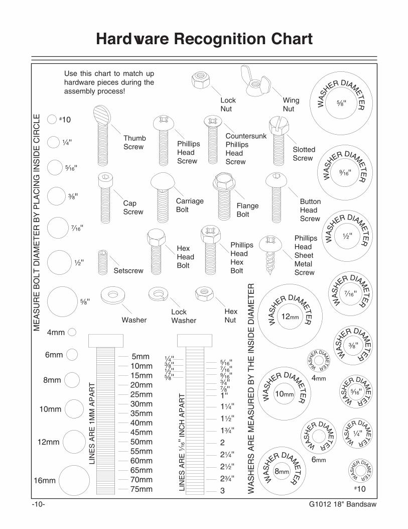
Hardware Recognition Chart
-10- G1012 18" Bandsaw
Use this chart to match uphardware pieces during theassembly process!

G1012 18" Bandsaw -11-
Clean up Site Considerations
• Floor Load: Your Model G1012 18"Bandsaw represents a moderate weight loadin a small footprint. Most commercial floorsare suitable for the Model G1012. Some res-idential floors may require additional build upto support both machine and operator.
• Working Clearances: Consider existing andanticipated needs, size of material to beprocessed through each machine, andspace for auxiliary stands, work tables orother machinery when establishing a loca-tion for your bandsaw.
• Lighting and Outlets: Lighting should bebright enough to eliminate shadow and pre-vent eye strain. Electrical circuits should bededicated or large enough to handle amper-age requirements. Outlets should be locatednear each machine so power or extensioncords are clear of high-traffic areas. Observelocal electrical codes for proper installationof new lighting, outlets or circuits.
The unpainted surfaces are coated with a waxyoil to protect them from corrosion during ship-ment. Remove this protective coating with a sol-vent cleaner or citrus-based degreaser such asGrizzly’s G7895 Degreaser. Avoid chlorine-based solvents as they may damage paintedsurfaces should they come in contact. Alwaysfollow the usage instructions on the product youchoose for clean up.
Make your shop “child safe.”Ensure that your workplaceis inaccessible to childrenby closing and locking allentrances when you areaway. Never allow visitors inyour shop when assembling,adjusting, or operatingequipment.
Do not use gasoline orother petroleum-basedsolvents to clean with.They have low flashpoints which make themextremely flammable. Arisk of explosion andburning exists if theseproducts are used .Serious personal injurymay occur.
Do not smoke while usingsolvents. A risk of explo-sion or fire exists and mayresult in serious personalinjury.
Many of the solventscommonly used to cleanmachinery can be toxicwhen inhaled or ingest-ed. Always work in well-ventilated areas far frompotential ignition sourceswhen dealing with sol-vents. Use care when dis-posing of waste rags andtowels to be sure they donot create fire or environ-mental hazards.

-12- G1012 18" Bandsaw
SECTION 4: ASSEMBLY
Keep loose clothing outof the way of machineryand keep hair pulledback, or serious injurymay occur.
Wear safety glasses dur-ing the entire assemblyprocess. Failure to com-ply may result in seriouspersonal injury.
Disconnect power to themachine when perform-ing any maintenance orassembly. Failure to dothis may result in seriouspersonal injury.
We have organized the assembly process of theModel G1012 into steps listed below. Please fol-low them in sequence. The inventory photos andlists, hardware recognition chart, parts list andexploded diagram have been provided to makeassembly as easy as possible.
1. Stand2. Motor3. Mounting Unit to Stand4. Wiring5. Pulley Alignment6. Table7. Fence Assembly8. Total Unit Check
Order of Assembly
NOTICETOOLS REQUIRED: In addition to the toolsprovided with your bandsaw, you will need ametric set of wrenches, large and mediumflat-tipped screwdrivers, a Phillips® screw-driver, and a 6" or 8" adjustable wrench.
To begin the stand assembly, locate all the standparts so they are within easy reach.
1. Flip the stand top upside down. Install thetwo adjustment bolts on the stand top byplacing the 3⁄8"-16 x 11⁄4" carriage boltsthrough the mounts on the stand top andthen the through eyes of the adjustmentbolts. Secure with 3⁄8" washers and hex nuts,but do not completely tighten.
2. Using (2) 3⁄8"-16 x 3⁄4" carriage bolts, wash-ers, and hex nuts; attach the motor bracketto the mounts on the stand top without tight-ening.
3. Place a 3⁄8"-16 hex nut and washer on eachadjustment bolt, then rotate the motor brack-et over the adjustment bolts, and secure withanother 3⁄8"-16 hex nut and washer so yourassembly looks like Figure 5. Again, do notcompletely tighten at this time.
Stand

G1012 18" Bandsaw -13-
4. Mount the motor onto the motor bracket.Secure with (4) 5⁄16" -18 x 3⁄4" hex head bolts,washers and nuts. Hand-tighten for now.
5. Place the smallest key in the groove on themotor shaft. Line up the key on the shaft withthe pulley keyway. Slide the motor pulley(the small triple-grooved pulley) onto themotor shaft. Insert one of the small 1⁄4"-20 x1⁄4" setscrews in the bottom of the middle pul-ley groove and tighten with the included3mm hex wrench as shown in Figure 6.
6. Attach the four legs to the top of the standusing the 5/16"-18 x 1/2" carriage bolts, wash-ers and nuts provided. Do not tighten downbolts completely at this time.
Figure 5. Motor bracket attached to stand top.
Figure 6. Securing motor pulley to motor shaft.
Figure 7. Legs, braces, and one stand sideattached to stand
Figure 8. Legs, braces, and both stand sidesassembled as an option.
7. Attach the two horizontal braces to the legsand secure with the 5/16"-18 x 1/2" carriagebolts, washers and nuts provided. Attachone of the stand sides on the opposite sideof the pulley slot in the stand top. Yourassembly should now look like Figure 7.
NOTICEAs an option, you may attach the otherstand side to the stand at this time.Performing this step now will ease assem-bly of this part, but it will limit your accessto the motor pulley when installing V-belts.
-14- G1012 18" Bandsaw
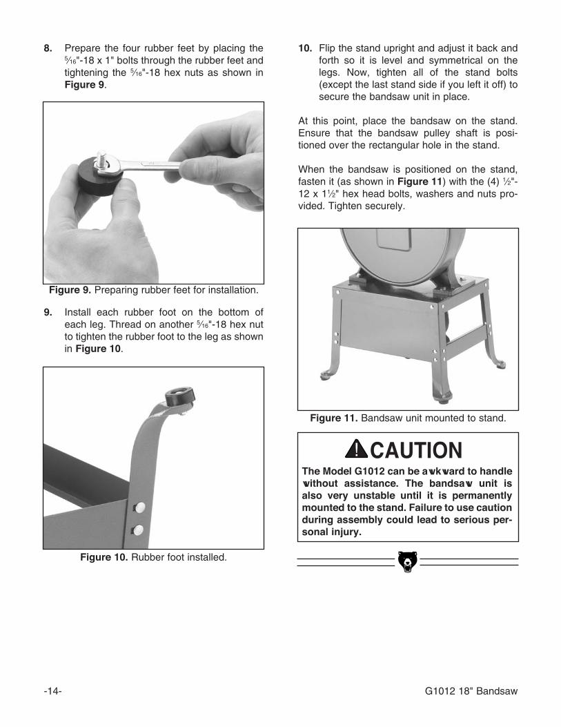
10. Flip the stand upright and adjust it back andforth so it is level and symmetrical on thelegs. Now, tighten all of the stand bolts(except the last stand side if you left it off) tosecure the bandsaw unit in place.
At this point, place the bandsaw on the stand.Ensure that the bandsaw pulley shaft is posi-tioned over the rectangular hole in the stand.
When the bandsaw is positioned on the stand,fasten it (as shown in Figure 11) with the (4) 1⁄2"-12 x 11⁄2" hex head bolts, washers and nuts pro-vided. Tighten securely.
The Model G1012 can be awkward to handlewithout assistance. The bandsaw unit isalso very unstable until it is permanentlymounted to the stand. Failure to use cautionduring assembly could lead to serious per-sonal injury.
Figure 11. Bandsaw unit mounted to stand.
Figure 9. Preparing rubber feet for installation.
Figure 10. Rubber foot installed.
8. Prepare the four rubber feet by placing the5⁄16"-18 x 1" bolts through the rubber feet andtightening the 5⁄16"-18 hex nuts as shown inFigure 9.
9. Install each rubber foot on the bottom ofeach leg. Thread on another 5⁄16"-18 hex nutto tighten the rubber foot to the leg as shownin Figure 10.

G1012 18" Bandsaw -15-
Figure 13. Securing wheel pulley to shaft.
Figure 12. Key in wheel pulley shaft.
Pulleys
With the bandsaw unit mounted firmly onto thestand, the pulleys need to be installed next.
1. Locate the upper pulley from your looseparts. Make sure the key is in the upper pul-ley shaft keyway as shown in Figure 12.
2. The wheel pulley is shaped so that it must beinstalled with the curved side out (look at theside profile of the wheel pulley to determinethis shape).
3. Align the the keyway in the pulley to the keyon the shaft and insert the wheel pulley asfar as it will go on the shaft. A few taps witha dead blow rubber hammer may be neces-sary to fit the wheel pulley all the way ontothe shaft.
4. Insert one of the 1⁄4"-20 x 1⁄4" setscrews intothe wheel pulley and tighten to the shaft asshown in Figure 13.
5. Install the stepped pulley through the open-ing in the bandsaw unit, directly below thewheel pulley.
6. Thread one of the 5⁄8"-11 hex nuts onto thestepped pulley shaft, followed by a 5⁄8" wash-er. Place this assembly through the openingin the bandsaw unit and secure with anotherwasher and hex nut from inside the bandsawunit. Leave the last hex nut loose enoughthat you can still move the stepped pulley forfurther adjustments.

-16- G1012 18" Bandsaw
5. To align pulleys, there is a variety of adjust-ment. For example:
A. The band wheel pulley can be slid along the shaft.
B. The three-step pulley can be adjusted away from the base by doubling up a washer.
C. The motor pulley can be turned around and repositioned on the motor shaft.
Remember, the motor should remain levelafter any adjustments.Figure 15. Pulley deflection w/moderate pressure.
V-Belts 3. Adjust the motor back and forth until the V-grooves line up with the V-grooves on thethree-step pulley.
4. Slip either the 31" or 33" belt over the motorpulley and the step pulley, depending on thedesired speed. For general woodworking, werecommend setting the lower belt for thefastest rate of speed. See Figure 16 forspeeds.
You may have to back off the nuts on themotor adjustment bolts to allow enoughmotor swing to attach the belt.
A32 Belt
Bandsaw Pulley
Step Pulley
Motor Pulley
A33 Belt2100 F.P.M.
A31 or A33 BeltA31 Belt3150 F.P.M.
2600 F.P.M.
Figure 16. Pulley speed chart.
In order to ensure proper power transmissionfrom motor to band wheels, the pulleys should bealigned and the belts should have proper tension.To begin pulley and belt assembly:
1. Place the A32 belt in the wheel pulley grooveand the last groove in the stepped pulley asshown in Figure 14.
2. Tension the belt by pushing the stepped pul-ley down in the shaft slot. The belt deflectionshould be approximately 3⁄4" when you pushon the center of the belt (similar to Figure15) with your index finger.
Figure 14. Stepped pulley installed with wheelpulley V-belt in place.

G1012 18" Bandsaw -17-
6. To tighten the belt from the stepped pulley tothe motor, loosen the nuts on each motoradjustment bolt and lower the motor intoposition. The weight of the motor is sufficientfor the amount of tension required. Tightenthe nuts against the motor plate, so yourassembly looks similar to Figure 17.
Belt Guard
Figure 18. Belt cover mounted to stand.
Figure 17. V-belts mounted on pulleys.
1. When all belts are installed, aligned, andtightened, fasten the last stand side to thestand legs. (If this has already been done,skip this step.)
2. Place the belt cover over the pulleys on thebandsaw unit and secure with the (2) 1⁄4"-20x 1⁄2" hex bolts, (4) 1⁄4" washers, and (2) 1⁄4"-20 hex nuts. Your assembly should now looksimilar to Figure 18.
DO NOT operate bandsaw with coverremoved or serious personal injury mayoccur!

-18- G1012 18" Bandsaw
Always keep the tapered table pin in placewhen operating the bandsaw.
To mount the table to the bandsaw unit:
1. Locate the trunnion casting from your looseparts. The mounting bolts are already in thetable saw unit, near the lower blade guides.Remove these bolts and their washers.
2. Line up the holes on the trunnion castingwith the roll pins that are in the bandsawunit.. Tap the trunnion casting down onto thebandsaw unit. Secure with the hex bolts andwashers as shown in Figure 19.
Table
Figure 19. Trunnion casting mounted to bandsaw unit.
Figure 21. Positive stop location/installation.
Figure 20. Table mounted on trunnion casting.
3. Using the table slot for access, remove thetable pin and guide the bandsaw tablearound the blade so the blade is centered inthe table. Rotate the table 90˚ and carefullyplace the table on the trunnions, so that thethreaded studs go through the holes in thetrunnions.
4. Using the two plastic knobs from your hard-ware bags, secure the table to the trunnionsas shown in Figure 20.
6. Fit the tapered table pin in the opening of theaccess slot.
7. After verifying that the positive stop holds thetable 90˚ to the blade, set the trunnion point-er to 0˚ on the trunnion gauge.
5. The Model G1012 includes a positive stopbolt for quick table adjustments. Locate the3⁄8"-16 x 3" hex bolt from your hardware bagand thread it into the trunnion casting asshown in Figure 21. Use a 3⁄8"-16 hex nutfrom the hardware bag to lock the bolt inplace.
Trunnion Pointer

G1012 18" Bandsaw -19-
The last item to install is the rip fence. Notice onthe front and back edge of the table there are (4)1⁄4" threaded holes. These holes accept the capscrews that secure the fence rails to the table.This assembly is illustrated in Figure 24.
1. Attach the rear fence rail to the table with the(4) 1⁄2" - 20 x 2" cap screws and spacers pro-vided.
2. If you wish to mount the fence to the left ofthe blade, the fence must be mounted to thefront rail before it is attached to the table.Otherwise, you will need to remove theblade to slide the fence over.
3. Secure the mounting bolts and ensure thatthe fence slides easily on the rails. Apply ashot of light oil or silicone spray to each railfor better movement. To remove the fencefrom the table, reverse steps 1-3.
To install the upper and lower blade guides:
1. Locate the eight blade guides from yourhardware bags. Insert the blade guides inthe holes that face the bandsaw blade.
2. Secure the blade guides by screwing thethumbscrews into the threaded holes thatintersect the blade guides as shown inFigure 23.
Figure 24. Attachment of fence rail to the table.
Table
Spacer
1/4" - 20 x 11⁄2" Socket Head Cap Screw
Fence
Blade Guides
Rail
This concludes assembly of the bandsaw.Please DO NOT operate this saw until youhave read and have followed the safetyinformation, adjustment and operation sec-tions in this manual. Operation withoutcomplete knowledge of this machine couldlead to serious operator injury or damage tothe machine or workshop.
Figure 22. Inserting roll pin in table.
7. Install the table insert in the center of thetable. Rotate the table insert so the notch inthe insert lines up with the notch in the tableto form a small hole. Locate the roll pin fromyour hardware bags and tap it into this smallhole as shown in Figure 22.
Thumbscrew
Blade Guides
Figure 23. Blade guide assembly.
-20- G1012 18" Bandsaw
SECTION 5: ADJUSTMENTS
Keep loose clothingrolled up and out of theway of machinery andkeep long hair pulledback.
Wear safety glasses dur-ing the entire adjustmentprocess. Failure to com-ply may result in seriouspersonal injury.
Disconnect power to themachine when perform-ing any maintenance orassembly. Failure to dothis may result in seriouspersonal injury.
A
B
D C
E
FG
F
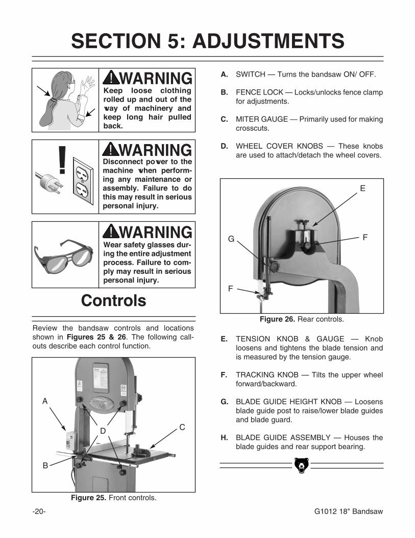
Review the bandsaw controls and locationsshown in Figures 25 & 26. The following call-outs describe each control function.
Controls
Figure 25. Front controls.
A. SWITCH — Turns the bandsaw ON/ OFF.
B. FENCE LOCK — Locks/unlocks fence clampfor adjustments.
C. MITER GAUGE — Primarily used for makingcrosscuts.
D. WHEEL COVER KNOBS — These knobsare used to attach/detach the wheel covers.
E. TENSION KNOB & GAUGE — Knobloosens and tightens the blade tension andis measured by the tension gauge.
F. TRACKING KNOB — Tilts the upper wheelforward/backward.
G. BLADE GUIDE HEIGHT KNOB — Loosensblade guide post to raise/lower blade guidesand blade guard.
H. BLADE GUIDE ASSEMBLY — Houses theblade guides and rear support bearing.
Figure 26. Rear controls.

G1012 18" Bandsaw -21-
Blade Tension
To adjust the tension:
1. Loosen the upper and lower guide blocksand raise the upper guide block as high as itwill go.
3. With moderate tension already on the blade,turn the bandsaw ON.
4. Release the tension one quarter of a turn ata time. Do this very slowly. When you seethe bandsaw blade start to flutter, stopdecreasing the tension.
5. Now, slowly increase the tension until theblade stops fluttering. Tighten the tensionone more quarter of a turn.
6. Look at what the tension gauge reads anduse that as a guide for tensioning your bladein the future.
If the tension seems correct, turn the bandsawOFF and make the other adjustments, and testrun. If the blade does not cut properly, the tensionmay be incorrect. Re-adjust the tension. Newblades often stretch with use. However, removingthe tension from the blade when not in use willreduce stretching and extend your blade life.
Blade Tracking
There are two ways to track a bandsaw blade:Center Tracking and Coplanar Tracking.Center Tracking is the fastest and easiest, but notthe most precise.
Center Tracking:
1. Disconnect the bandsaw from the powersource!
2. Adjust the upper and lower guide blocks andsupport bearings away from the blade.Remove the upper wheel cover.
3. Adjust blade tension to how it will be usedduring operation.
4. Loosen the tracking control lock nut. Turnthe tracking control knob clockwise/counter-clockwise while turning the upper wheel byhand until the blade stays centered on thewheel.
5. Spin the upper wheel by hand at least threetimes to ensure that the blade stays cen-tered. If the blade does not stay centered, re-adjust as necessary.
6. Tighten the tracking control lock nut andreplace the upper wheel cover.
For the best performance from your saw, regular-ly maintain proper tracking of the blade.
For Coplanar Tracking, see the “WheelAlignment” instructions.
Be careful when turning the band wheels byhand. The aluminum spokes may havesharp edges and the blade teeth may extendbeyond the edge of the wheel.

-22- G1012 18" Bandsaw
Figure 28. Proper guide block adjustment.
Guide-Block Holder
Guide-Blocks
Space .004" Each SideBlade
Whenever changing a blade or adjusting tensionand tracking, the upper and lower blade supportbearings and guide-blocks must be re-adjusted.Always loosen the thumbscrews/setscrews andknobs and adjust the assemblies away beforeinstalling a new blade or making blade adjust-ments. After blade tension and tracking are setcorrectly, re-adjust the upper and lower supportbearings and guide-block assemblies into posi-tion.
UPPER BLADE GUIDE ASSEMBLIES
The guide-blocks support the blade from bothsides. The steel guide-blocks should be set .004"from the blade as illustrated in Figure 27. Theguide-block holder should be adjusted so thefront blocks are 1⁄16" behind the saw gullets.
To set the guide-blocks within the guide-block holder:
Blade Guides
Always disconnectpower to the machinewhen making adjust-ments. Failure to do thismay result in seriouspersonal injury.
3. Note where the blade is in the guide blockholder. It should be roughly centered. If it isnot centered, loosen the hex bolt thatsecures the blade guide assembly to theguide post.
4. Rotate the guide assembly so the blade iscentered between each side of the guideblock holders.
5. Tighten the hex nut that secures the bladeguide assembly to the guide post.
Guide Post
Guide Post
Figure 27. Tension and guide post controls.
The guide post (shown in Figure 30) is adjustableso the guide blocks will stay aligned with theblade when the guide post is raised or lowered.
To adjust guide assembly alignment on guidepost:
1. Adjust blade tension and tracking.
2. Loosen the guide blocks in the upper andlower guide assemblies.
1. Loosen the setscrews locking the guide-blocks in the guide-block holder.

G1012 18" Bandsaw -23-
The support bearings back-up the blade duringthe sawing operation. To adjust the upper sup-port bearing, loosen the shaft setscrew. Theupper blade support bearing should be adjustedto within .016" (four thicknesses of a dollar bill)behind the blade as shown in Figure 29.Retighten the shaft setscrew.
LOWER BLADE GUIDE ASSEMBLIES
The lower blade guide assemblies should beadjusted to the same tolerances as the upperguide assemblies.
1. Adjust lower support bearing to within .016"from the rear of the blade.
2. Adjust lower guide-blocks to .004" fromblade sides.
3. Adjust lower guide-block holder to within 1⁄16"behind blade gullets.
4. Secure all adjustment knobs and screws.
5. Make sure the blade tracks true. Inspect forany blade deflection caused by incorrectpositioning of the guide blocks. The supportbearings should rotate only under load.
Figure 29. Single dollar thickness on each sideof the blade.
Figure 30. Dollar folded twice for support bearing adjustment.
2. Clearance between the blade and the guide-blocks should be .004" (similar to the thick-ness of a dollar bill). For an easy gauge, folda dollar bill in half and place each half oneach side of the blade as in Figure 28.
3. Adjust the guide blocks and lock into positionby tightening the thumbscrews. Remove thedollar.

-24- G1012 18" Bandsaw
The bandsaw table will tilt 5˚ left and 45˚ rightfrom horizontal. There is an adjustable positivestop so the table can be reset perpendicular tothe blade after tilting to the right. To tilt the table:
1. Loosen the two plastic knobs underneath thetable as shown in Figure 31.
2. Position the table to the desired angle of tilt.Refer to the angle gauge on the front tabletrunnion for the tilting angle.
3. Retighten both plastic knobs.
Table Adjustments
Figure 31. Plastic trunnion knobs.
Blade Changes
To remove the blade:
1. Unplug the bandsaw!
2. Release tension on the blade by turning thetension control knob counter-clockwise.
3. Remove the table insert and the table pin.Adjust the upper and lower guide blocksaway from the blade.
4. Put on leather gloves to protect your handsfrom the sharp teeth of the blade.
5. Open the upper and lower wheel covers andslide the blade off both wheels. Use caution— the blades are sharp!
6. Rotate the blade 90˚ so it will slide throughthe slot in the table.
Always disconnectpower to the machinewhen changing blades.Failure to do this mayresult in serious person-al injury.
When removing or installing wide blades, it maybe convenient to completely remove the upperand lower guide blocks. Be sure to replace thembefore cutting. To replace the blade:
1. Slide the blade through the table slot, ensur-ing that the teeth are pointing down towardthe table.
If the teeth will not point downward in any ori-entation, the blade is inside-out. Put onheavy gloves, remove the blade, and twist itrightside-out.
Wear gloves and safety goggles when han-dling blades. Coiled blades spring open asthey are uncoiled and could cause deeppunctures or lacerations.
2. Slip the blade through the upper and lowerguides, and mount it over the upper andlower wheels.
3. Apply tension, then check and adjust track-ing.
4. Adjust the upper and lower guide blocks andthe support bearings.
5. Close and tighten the wheel covers.
6. Replace the table insert and table pin, beingsure not to use excessive force when insert-ing the table pin.

G1012 18" Bandsaw -25-
NOTICEIf setting table tilt to the left, it will be nec-essary to remove the positive stop.
To adjust the positive stop so the table will be90° to the blade:
1. Loosen the two plastic knobs and check-nutthat secure the positive stop adjusting boltshown in Figure 32.
2. Raise the upper blade guide assembly andplace a 6" machinist’s square or try-squareon the table next to the side of the blade.Adjust the positive stop adjusting bolt toraise or lower the table until the table is 90˚to the blade.
Figure 32. Squaring table to blade.
Figure 34. Squaring table to blade back.
Figure 33. Squaring table to blade.
3. Secure the plastic knobs and lock the posi-tive stop adjusting bolt by tightening thecheck-nut. Ensure that the bolt does not turnwhile tightening the check-nut.
To adjust the miter slot parallel to the band-saw blade:
1. Loosen the six trunnion bolts underneath thetable.
2. Place a good straightedge along the blade.The straightedge should touch the front andthe back of the blade. Use a fine ruler togauge the distance between the blade andthe miter slot as shown in Figure 33. Thedistance you measure should be the same atboth the front and the back of the table.
3. Adjust the table in the desired direction andsecure in position by retightening the trun-nion bolts.
The table should also be 90˚ to the back of theblade as shown in Figure 34. If you should findthat the table is not perpendicular to the back ofthe blade, shim the table in the desired directionby placing washers between the table and thetwo trunnions.
Remove the trunnion bolts and add washers sothe table tilts in the desired direction. Electricalwashers are very thin and will allow fine adjust-ment.
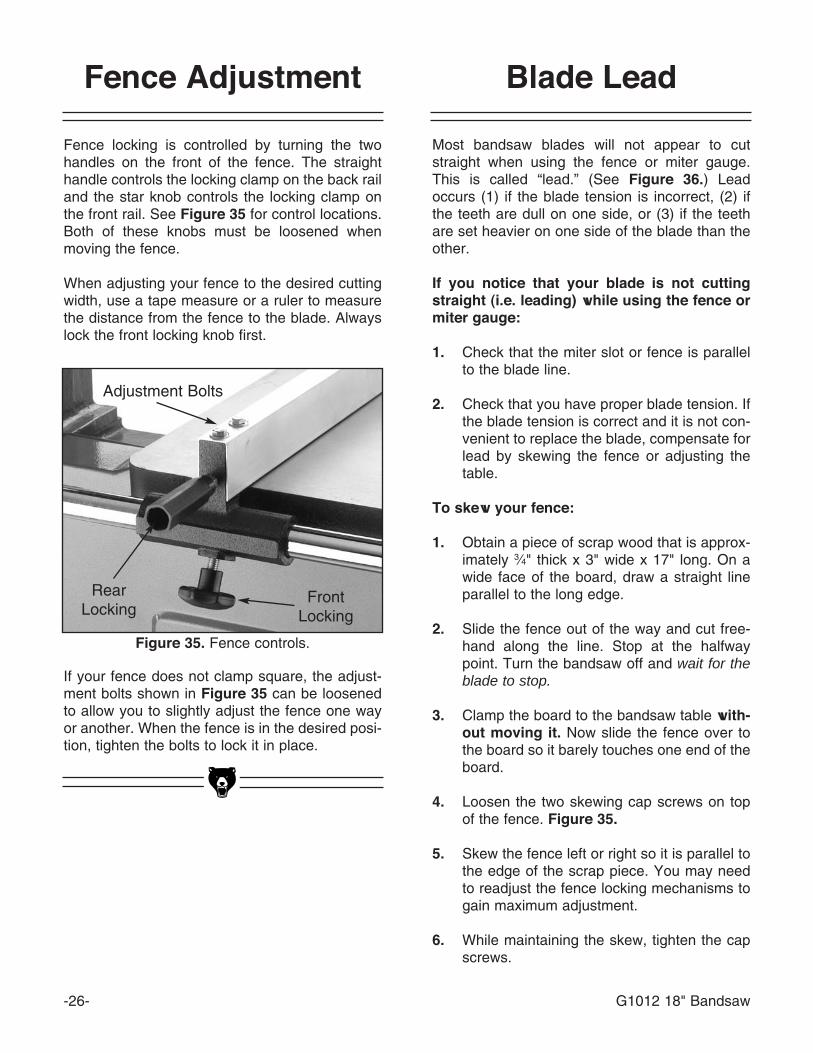
Fence Adjustment
Fence locking is controlled by turning the twohandles on the front of the fence. The straighthandle controls the locking clamp on the back railand the star knob controls the locking clamp onthe front rail. See Figure 35 for control locations.Both of these knobs must be loosened whenmoving the fence.
When adjusting your fence to the desired cuttingwidth, use a tape measure or a ruler to measurethe distance from the fence to the blade. Alwayslock the front locking knob first.
Figure 35. Fence controls.
If your fence does not clamp square, the adjust-ment bolts shown in Figure 35 can be loosenedto allow you to slightly adjust the fence one wayor another. When the fence is in the desired posi-tion, tighten the bolts to lock it in place.
-26- G1012 18" Bandsaw
FrontLocking
RearLocking
Adjustment Bolts
Blade Lead
Most bandsaw blades will not appear to cutstraight when using the fence or miter gauge.This is called “lead.” (See Figure 36.) Leadoccurs (1) if the blade tension is incorrect, (2) ifthe teeth are dull on one side, or (3) if the teethare set heavier on one side of the blade than theother.
If you notice that your blade is not cuttingstraight (i.e. leading) while using the fence ormiter gauge:
1. Check that the miter slot or fence is parallelto the blade line.
2. Check that you have proper blade tension. Ifthe blade tension is correct and it is not con-venient to replace the blade, compensate forlead by skewing the fence or adjusting thetable.
To skew your fence:
1. Obtain a piece of scrap wood that is approx-imately 3⁄4" thick x 3" wide x 17" long. On awide face of the board, draw a straight lineparallel to the long edge.
2. Slide the fence out of the way and cut free-hand along the line. Stop at the halfwaypoint. Turn the bandsaw off and wait for theblade to stop.
3. Clamp the board to the bandsaw table with-out moving it. Now slide the fence over tothe board so it barely touches one end of theboard.
4. Loosen the two skewing cap screws on topof the fence. Figure 35.
5. Skew the fence left or right so it is parallel tothe edge of the scrap piece. You may needto readjust the fence locking mechanisms togain maximum adjustment.
6. While maintaining the skew, tighten the capscrews.

G1012 18" Bandsaw -27-
Figure 36. Blade leading away from line of cut.
To compensate for lead if making straightcrosscuts using the miter gauge, you willneed to shift the table. To do this:
1. On a scrap piece of wood, mark a line that isperpendicular to the front edge. Startingwhere the line begins, cut the board by push-ing it through the blade with the miter gauge.
2. Loosen the table mounting bolts according tothe instructions about “Table Adjustments”on page 20. Shift the table to compensatefor the blade lead.
3. Repeat steps 1 and 2 until the blade cutsstraight when wood is pushed through withthe miter gauge.
NOTICELead adjustments will change when newblades are mounted on the saw.
NOTICEIf the table is shifted, the fence will beaffected since it is attached.
Wheel Alignment
Wheel alignment is one of the easiest ways toensure you get optimal performance from yourbandsaw. When wheels are aligned, or coplanar,the bandsaw is more likely to cut straight withoutwandering; and vibration, heat, and blade wearare considerably decreased because the blade isautomatically balanced on the wheel. This isknown as “Coplanar Tracking.”
To verify if the the upper and lower wheels arecoplanar:
1. With the blade on and properly tensioned,hold a straightedge close to the center ofboth wheels. Make sure it fully extendsacross them as shown in Figure 37.
Figure 37. Checking wheel alignment with astraightedge.
2. A perfectly coplanar set of wheels will allowthe straightedge to touch the top and bottomof the outside rims on each wheel. If this isthe case with your wheels, then they arecoplanar.
3. If your wheels are not coplanar, check themfor adjustment by placing the straightedgeon the lower wheel first – ensuring that ittouches both the top and bottom rim – andadjust the tracking knob to see how thestraightedge lines up with the upper wheel.

-28- G1012 18" Bandsaw
Figure 39. Coplanar diagram.
Figure 38. Measuring wheel difference.
4. Replace the wheel, any remaining washers,and the securing nut. Tighten the blade as itwill be used during operation before youcheck the wheels for being coplanar. Oftenthe wheels may be coplanar with the bladeloose, then be pulled out of alignment whenit is tightened.
5. The first time you get the wheels coplanar,place a mark on each wheel where you heldthe straightedge. This assures repeatedaccuracy every time you adjust your wheels.
When wheels are properly coplanar, the blademay not be centered on the crown of the wheel,but it will be balanced. See Figure 39 to betterunderstand coplanarity.
2. Remove the blade from the saw, thenremove the securing nut and the washersfrom the wheel that needs to be shimmed.Take the wheel off.
3. Electrical washers work well for shimmingbecause they are offered in a wide range ofthicknesses. Measure how many you willneed and place them on the mounting shaft.
If the straightedge will not touch the top and bot-tom rim of the upper wheel evenly, first determineif the upper wheel needs to be moved forward orbackward. You can only shim the wheels to comeforward.
• If the front wheel is behind the straightedgethen the front wheel can be shimmed.
• If the front wheel is comes forward from theplane of the lower wheel, the lower wheelneeds to be shimmed forward, so thestraightedge lines up even with both wheels.
Shimming a wheel:
1. Adjust the tracking knob so the top wheel isparallel with the bottom wheel. With thestraightedge touching both points of thewheel that does not need to be adjusted,measure the distance away from the incor-rect wheel with a fine ruler. See Figure 38.The distance you measured with the ruler isthe distance the wheel must be corrected.

G1012 18" Bandsaw -29-
Once the assembly is complete and the adjust-ments are done to your satisfaction, you areready to test the machine.
Turn on the power supply at the main panel. Pullthe paddle switch up to start the bandsaw. Makesure that your hand is poised over the switch incase there is a problem. The bandsaw should runsmoothly with little or no vibration or rubbing nois-es. Strange or unnatural noises should be inves-tigated and corrected before operating themachine further.
If you cannot easily locate the source of anunusual noise or vibration, feel free to contact ourservice department for help.
Test Run
SECTION 6: OPERATIONS
Keep loose clothingrolled up and out of theway of machinery andkeep hair pulled back.
Wear safety glasses dur-ing the entire operationprocess. Failure to com-ply may result in seriouspersonal injury.
Disconnect power to themachine when perform-ing any maintenance orassembly. Failure to dothis may result in seriouspersonal injury.
Overview
The bandsaw is one of the most versatile woodcutting tools in the shop. It is capable of perform-ing many different cutting functions including, butnot limited to:
STRAIGHT CUTS• Miters• Angles• Compound Angles• Resawing• Ripping• Crosscutting
IRREGULAR CUTS• Simple and Complex Curves• Duplicate Parts• Circles• Beveled Curves
NOTICEThe following section was designed to giveinstructions on the basic operations of thisbandsaw. However, it is in no way compre-hensive of every bandsaw application. Thereare many different jigs that can be built toincrease safety, accuracy, and types of cuts.WE STRONGLY RECOMMEND that you readbooks, trade magazines, or get formal train-ing to maximize the potential of yourmachine.
Using this machine pro-duces sawdust which maycause allergic reactionsand respiratory problems.Use an approved dustmask to protect yourselffrom these hazards!

-30- G1012 18" Bandsaw
Do not force the material against the blade, uselight and even pressure. Light contact with theblade will permit easier line following and preventundue friction, heat and work-hardening alongthe back edge of the blade.
Avoid trying to turn sharp corners because thiswill twist the blade. Remember, you must sawaround corners.
NOTICESet the top guide assembly so it is justabove the top of the work at all times.
Blade InformationAlthough you can perform many types of straightcuts such as angling and mitering on the band-saw, they will not be as precise as on a table saw.Also, since the blade is flexible, the resulting cutis somewhat rougher than one performed on atable saw. However, just as a table saw is suitedto precision straight cuts and miters, the bandsawexcels when resawing and when cutting irregularshapes. A properly adjusted and tuned up band-saw is also safer to operate than most other sawsand is capable of performing many sawing func-tions with ease and accuracy.
A common fault when using a bandsaw is blam-ing the saw for not performing up to expectations.Many factors contribute to the performance of abandsaw. Using the wrong kind of blade for thejob or using a poor quality blade will result inunsatisfactory performance. Misuse of the saw orusing incorrect sawing techniques can be unsafeas well as result in frustration and poor cuts.Remember, the blade does the cutting with theoperator’s guidance. Replace and clean bladesas necessary and make adjustments periodicallyto keep the saw always running in top condition.
Selecting the right blade requires a combinationof the various blade characteristics mentionedbelow, the type of material you plan to cut, andthe type of cut you are going to perform.
Blade Length
Measured by the circumference, blade lengthsare usually unique to the brand of your bandsawand the wheel diameter. The Model G1012 isdesigned for blades that are 124" long. However,the tension adjustment will accommodate bladesup to a maximum length of 125" and down to aminimum of approximately 123" in length.
Blade Width
Measured from the the back of the blade to the tipof the blade tooth (the widest point), blade widthis often the first consideration given to bladeselection.
A narrow blade can cut tight curves (a smallradius) but is not very good at cutting straightlines, because they naturally wander (bladelead). However, larger blades are much better atcutting straight lines, but function poorly at cuttingsmall curves because of their size.
The Model G1012 functions best with 1⁄4", 3⁄8", 1⁄2",1" and 11⁄2" widths. Refer to the current Grizzlycatalog for prices and ordering information.Always pick the size of blade that best suits yourapplication.
Tooth Style
When selecting blades, another option to consid-er is the shape, gullet size and angle of the teeth— otherwise known as “Tooth Style.”
Figure 40 shows the three main categories oftooth style:

G1012 18" Bandsaw -31-
• RAKER — This style is considered to be thestandard because the tooth size and shapeare the same as the tooth gullet. The teethon Raker blades usually are very numerous,have no angle, and produce cuts by scrapingthe material; these characteristics result invery smooth cuts, but at the same time donot cut fast and generate more heat whilecutting.
• SKIP — This style is similar to a raker bladethat is missing every other tooth. Because ofthe design, skip toothed blades have a muchlarger gullet than raker blades, and there-fore, cut faster and generate more heat.However, these blades also leave a roughercut than raker blades.
• HOOK — The teeth on this style have a pos-itive angle (downward) which makes themdig into the material, and the gullets are usu-ally rounded for easier waste removal.These blades are excellent for the toughdemands of resawing and ripping thick mate-rial.
Tooth Pitch
Usually measured as T.P.I. (teeth per inch), toothpitch determines the size of the teeth. More teethper inch (fine pitch) will cut slower, but smoother;while fewer teeth per inch (coarse pitch) will cutrougher, but faster. As a general rule, choose
Figure 40. Raker, Skip & Hook tooth styles.
Raker Skip Hook
blades that will have at least three teeth in thematerial at all times. Use fine pitched blades onharder woods and coarse pitched blades on soft-er woods.
Blade Care
A bandsaw blade is a delicate piece of steel thatis subjected to tremendous strain. You can obtainlonger use from a bandsaw blade if you give it fairtreatment and always use the appropriate feedrate for your operation.
Be sure to select blades with the proper width,style, and pitch for each application. The wrongchoice of blades will often produce unnecessaryheat which will shorten the life of your blade.
A clean blade will perform much better than adirty blade. Dirty blades pass through the cuttingmaterial with much more resistance than cleanblades. This extra resistance also causes unnec-essary heat.
Blade Breakage
Many conditions may cause a bandsaw blade tobreak. Blade breakage is unavoidable, in somecases, since it is the natural result of the peculiarstresses that bandsaw blades are subjected to.Blade breakage is also due to avoidable circum-stances. Avoidable breakage is most often theresult of poor care or judgement on the part of theoperator when mounting or adjusting the blade orsupport guides.
The most common causes of blade breakage are:(1) faulty alignment and adjustment of the guides, (2) forcing or twisting a wide blade around a curveof short radius, (3) feeding too fast, (4) tooth dull-ness or absence of sufficient set, (5) excessivetension, (6) top blade guide assembly set too highabove the work piece, (7) using a blade with alumpy or improperly finished braze or weld and(8) continuously running the bandsaw when not inuse.

-32- G1012 18" Bandsaw
Ripping
Crosscutting
Ripping is the process of cutting with the grain ofthe wood stock. For plywood and otherprocessed wood, ripping simply means cuttingdown the length of the workpiece.
To rip with the Model G1012:
1. Using a straightedge or other accurateguide, lightly pencil the workpiece along thedesired path of cut.
2. Place the workpiece even along the fenceand line up the penciled mark with the blade,having the blade kerf on the waste portionside of the workpiece. Lock the front andback of the fence in place.
3. Making sure all safety precautions havebeen taken, start the bandsaw. Slowly feedthe workpiece into the blade and continuewith the cut until the blade is completelythrough the workpiece. Figure 41 shows atypical ripping operation. When cutting nar-row pieces, use a push stick to protect yourfingers.
Figure 41. Ripping with a push stick.
NEVER place fingers or hands in the line ofcut. In the event that something unexpectedhappens, your hands or fingers may bepulled into the blade. ALWAYS use a pushstick when ripping narrow pieces. Failure tofollow these warnings may result in seriouspersonal injury!
Crosscutting is the process of cutting across thegrain of wood. For plywood and other processedwood, crosscutting simply means cutting acrossthe width of the material.
To crosscut with the Model G1012:
1. Using a straightedge or other accurate guideand lightly pencil the workpiece along thedesired path of cut.
2. Move the fence out of the way. Place theworkpiece evenly against the miter gauge.
3. Line up the penciled mark with the blade,having the blade kerf poised to cut throughthe waste portion of the workpiece.
4. After all safety precautions have been met,start the bandsaw. Slowly feed the work-piece into the blade and continue the cutuntil it is all the way through the workpiece.Figure 42 shows a typical crosscutting oper-ation.

G1012 18" Bandsaw -33-
Figure 43. Resawing lumber.
1. The bandsaw must be adjusted correctly.See Section 5: Adjustments.
2. The table must be square to the blade.
3. Use the widest blade available. The blademust also be in good condition.
4. Use a fence to guide the work.
5. Draw a reference line on the edge of theboard.
6. Support the ends of the board if necessary.
7. Feed the workpiece slowly and evenly.
Resawing (Figure 42) is the process of cutting aboard into two or more thinner boards. The max-imum board width that can be resawn is limitedby the maximum cutting height of the bandsaw.Maximum cutting height for this bandsaw is 91⁄2".
The Model G1012 18" Bandsaw is capable ofresawing, provided the saw is set up properly.Use common sense when resawing. Attemptingto resaw too wide or too dense of a board mayput excessive strain on the blade and be danger-ous.
The important consideration when resawing isblade selection. Generally, the wider blade, thebetter. In most applications, a hook or a skip toothstyle will be desirable. Also, since most resawnlumber will be planed smooth, you should chooseblades with fewer teeth-per-inch (from 3 to 6).While blades with fewer teeth-per-inch producerougher cuts, these types of blades offer largergullet capacities for clearing sawdust. They alsoproduce less heat buildup and yield more horse-power per tooth.
Resawing
Figure 42. Crosscutting with miter gauge.

-34- G1012 18" Bandsaw
Stacked Cuts
To complete a stacked cut:
1. Align your pieces from top to bottom toensure that each piece has adequate scrapto provide a clean, unhampered cut.
2. Secure all the pieces together in a mannerthat will not interfere with the cutting. Hotglue on the edges works well, as does bradnails through the waste portion. (Be carefulnot to cut into the brads!)
3. On the face of the top piece, lay out theshape you intend to cut.
4. Make relief cuts perpendicular to the outlineof your intended shape in areas wherechanges in blade direction could strain thewoodgrain or cause the blade kerf to bind.
5. Cut the stack of pieces as though you werecutting a single piece. Follow your layout linewith the blade kerf on the waste side of yourline as shown in Figure 44.
Cutting Curves
When cutting curves, simultaneously feed andturn the stock carefully so that the blade followsthe layout line without being twisted. If a curve isso abrupt that it is necessary to repeatedly backup and cut a new kerf, use either a narrowerblade or a blade with more T.P.I. A blade withmore T.P.I. can cut relatively tighter radii, thoughthe cut is usually rougher than cuts produced bya blade with a medium amount of T.P.I.
Always make short cuts first, then proceed to thelonger cuts. Relief cuts will also reduce thechance that the blade will be pinched or twisted.Relief cuts are cuts made through the waste por-tion of the workpiece and are stopped at the lay-out line. As you cut along the layout line, wastewood is released from the workpiece, alleviatingany pressure on the back of the blade. Relief cutsalso make backing the workpiece out easier, ifneeded.
NOTICEThe table below lists blade widths and cor-responding minimum radii each blade willcut.
Width Radius3⁄8'' ..............................11⁄2''1⁄2'' ..............................21⁄2''3⁄4'' ..............................51⁄2''1'' ................................6''11⁄2'' ............................8''
One of the benefits of a bandsaw is its ability tocut multiple copies of a particular shape by stack-ing a number of workpieces together.
Before making stacked cuts, it is essential toensure that both the table and the blade are prop-erly adjusted to 90°. Otherwise, any error will becompounded with each piece cut from the top tothe bottom of the stack.
Cutting into brad nails that are used tosecure the multiple pieces can cause theblade to brake and may cause an injury tothe operator. Be extremely careful of whereyou are cutting when performing this oper-ation.
Figure 44. Cutting multiple pieces at once.

G1012 18" Bandsaw -35-
SECTION 7: MAINTENANCE
V-Belts
To ensure optimum power transmission from themotor to the blade, the V-belt must be in goodcondition and operate under proper tension. Thebelts should be checked for cracks, fraying andwear. Belt tension should be checked at leastevery 3 months — more often if the bandsaw isused daily.
The V-belt is accessed via the bottom cover:
1. Push the center of the V-belt.
2. Note the amount of deflection. Deflectionshould be approximately 3⁄4". See “V-BeltAdjustment” instructions to adjust.
The table and other non-painted surfaces on theModel G1012 should be protected against rustand pitting. Wiping the saw clean after every useensures that wood dust is not allowed to trapmoisture against bare metal surfaces.
The table can be kept rust-free with regular appli-cations of products like Boeshield® T-9. For longterm storage you may want to consider productslike Kleen Bore's Rust Guardit™. See the currentGrizzly catalog for more on these products.
Table
Sealed and pre-lubricated ball bearings requireno lubrication for the life of the bearings. All bear-ings are standard sizes, and replacements canbe purchased from our parts department or bear-ing supply store.
As for other items on this machine, such asadjustment controls, an occasional “shot” of lightoil is just about all that is necessary. Beforeapplying, however, wipe off any sawdust with aclean cloth, towel or dry paint brush, and spray onthe lubricant. Ensure that oil does not get on thepulleys or V-belt because it could cause belt dete-rioration and slipping.
Lubrication
Always be aware of the condition of your band-saw. Routinely check the condition of the follow-ing items and repair or replace as necessary:
• Loose mounting bolts
• Worn switch
• Worn or damaged blade
• Worn or damaged support bearings or guidebearings
Miscellaneous
Always disconnectpower to the machinewhen making adjust-ments. Failure to do thismay result in seriouspersonal injury.

-36- G1012 18" Bandsaw

G1012 18" Bandsaw -37-
The following pages contain general machinedata, parts diagrams/lists, troubleshooting guideand Warranty/Return information for your ModelG1012 18" Bandsaw.
If you need parts or help in assembling yourmachine, or if you need operational information,we encourage you to call our ServiceDepartment. Our trained service technicians willbe glad to help you.
If you have comments dealing specifically withthis manual, please write to our Bellingham,Washington location using the address in theGeneral Information section. The specifications,drawings, and photographs illustrated in thismanual represent the Model G1012 as suppliedwhen the manual was prepared. However, due toGrizzly’s policy of continuous improvement,changes may be made at any time with no oblig-ation on the part of Grizzly.
We have included some important safety mea-sures that are essential to this machine’s opera-tion. While most safety measures are generallyuniversal, Grizzly reminds you that each work-shop is different and safety rules should be con-sidered as they apply to your specific situation.
We recommend you keep a copy of our currentcatalog for complete information regardingGrizzly's warranty and return policy. If you needadditional technical information relating to yourmachine, or if you need general assistance orreplacement parts, please contact the ServiceDepartment listed in the General Informationsection.
Additional information sources are necessary torealize the full potential of your machine. Tradejournals, woodworking magazines, and your locallibrary are good places to start.
SECTION 8: CLOSURE
Like all power tools, there is danger associ-ated with the Model G1012 18" Bandsaw.Use the tool with respect and caution tolessen the possibility of mechanical dam-age or operator injury. If normal safety pre-cautions are overlooked or ignored, seriouspersonal injury may occur.
The Model G1012 was specifically designedfor wood cutting operations. DO NOT MODI-FY AND/OR USE THIS BANDSAW FOR ANYOTHER PURPOSE. Modifications or improp-er use of this tool will void the warranty. Ifyou are confused about any aspect of thismachine, DO NOT use it until all your ques-tions are answered. Serious personal injurymay occur.
Operating this equipment has the potentialfor flying debris to cause eye injury. Alwayswear safety glasses or goggles when oper-ating equipment. Everyday glasses or read-ing glasses only have impact resistant lens-es, they are not safety glasses. Be certainthe safety glasses you wear meet the appro-priate standards of the American NationalStandards Institute (ANSI).

-38- G1012 18" Bandsaw
Customer Service #: (570) 546-9663 • To Order Call: (800) 523-4777 • Fax #: (800) 438-5901
GRIZZLY MODEL G1012 18" BANDSAW
MACHINE DATASHEET
Design Type:......................................................................................................Floor Model
Overall Dimensions:Table ....................................................................................................18" x 18" x 11⁄2"Height from Floor to Table........................................................................................38"Height Overall ..........................................................................................................71"Width Overall ............................................................................................................33''Depth Overall............................................................................................................26''Shipping Weight ................................................................................................350 lbs.Weight in Place ................................................................................................266 lbs.Crate Size ..............................................................................................18" x 26" x 60"Foot Print ..................................................................................................241⁄2" x 201⁄2"
Cutting Capacity:Left of Blade ..........................................................................................................173⁄8"Height ......................................................................................................................10"Table Tilt ......................................................................................................5° L 45° R
Construction:Table ..................................................................................Precision Ground Cast IronBody ................................................................................................................Cast IronWheels ............................................Fully Balanced Cast Aluminum with Rubber TiresRip Fence ..................................Double Lock, Adjustable, Extruded Aluminum GuideWheel Covers....................................................................................Pre-Formed SteelBlade Guides..........................................Steel Blocks With Rear Ball Bearing Support
Motor:Type ............................................................................TEFC Capacitor Start InductionHorsepower..........................................................................................................2 H.P.Phase ⁄ Cycle ..............................................................................Single Phase ⁄ 60 HzSwitch ................................................220V Magnetic w/ Thermal Overload ProtectionVoltage ..................................................................................110/220V-prewired 220VAmps ..................................................................................................................12 / 24R.P.M. ....................................................................................................................3450Bearings ....................................................Shielded and Permanently Lubricated Ball
Blade:Sizes Available ................................................................................................1⁄8" - 11⁄4"Standard Blade Length ..........................................................................................124"Blade Speeds ..................................................2100 F.P.M., 2600F.P.M., 3150 F.P.M.
Accessories:....................................................................Includes: Fence, Miter Gauge & 1" Blade
Specifications, while deemed accurate, are not guaranteed.

G1012 18" Bandsaw -39-

-40- G1012 18" Bandsaw

G1012 18" Bandsaw -41-

-42- G1012 18" Bandsaw

G1012 18" Bandsaw -43-
REF PART # DESCRIPTION REF PART # DESCRIPTION
001 P1012001 UPPER FRAME ARM002 P1012002 LOCK KNOB003 P1012003 SWITCH PLATE004 P1012004 GUIDE POST005 P1012005 SUPPORT BRACKET 7⁄8" I.D.06A P1012006 THUMB SCREW 1⁄4"-20 X 3⁄8"007 P1012007 GUIDE BLOCK HOLDER008 P1012008 ROUND GUIDE BLOCK009 PB51 HEX BOLT 1⁄4"-20 X 3⁄8"010 PW06 FLAT WASHER 1⁄4"011 PB05 HEX BOLT 1⁄4"-20 X 3⁄4"012 P1012012 GUARD PLATE013 P1012013 HEX SHAFT014 P6200 BALL BEARING 6200015 PR01M EXT RETAINING RING 10MM016 P1019Z033 BLADE ADJUSTING SCREW017 P1012017 UPR WHEEL SLIDING BRKT018 P1012018 SPRING019 P1019017 SQUARE NUT 3⁄8"-16020 P1019018 ADJUSTMENT KNOB021 PN02 HEX NUT 5⁄16"-18022 PB51 HEX BOLT 1⁄4"-20 X 3⁄8"024 P1019021 STEEL PIN025 PRP16M ROLL PIN 3 X 25027 P6202 BALL BEARING 6202ZZ028 P1012028 UPPER WHEEL029 P1012029 WHEEL PROTECTOR030 P1012030 UPPER WHEEL GUARD (IN)031 P1012031 STUD032 P1012032 UPPER WHEEL GUARD (O)033 PB41 HEX BOLT 1⁄2"-12 X 11⁄2"034 PW01 FLAT WASHER 1⁄2"035 PN06 HEX NUT 1⁄2"-12036 PR21M INT. RETAINING RING 35MM037 PW06 FLAT WASHER 1⁄4"
038 P1012038 PIN039 P1012039 HEX BOLT 5/8"-11 X 21⁄2"040 PW14 FLAT WASHER 5⁄8"041 P1012041 BASE41A P1012041A BEARING HOUSING042 PN04 HEX NUT 5⁄8"-11044 P1012044 TABLE INSERT45A PRP44M ROLL PIN 3 X 10046 P1012046 TAPERED PIN047 P1012047 TABLE048 PB35 HEX BOLT 3⁄8"-16 X 21⁄2"049 P1012049 TRUNNION CLAMP SHOE050 P1012050 TRUNNION051 P1012051 TRUN SUPPORT BRACKET052 P1012052 LOCK KNOB FOR TABLE52A P1012052A COVER KNOB053 P1012053 INDICATOR054 P1012054 GAUGE55A PB06 HEX BOLT 5⁄16"-16 X 2"056 P1012056 HEX BOLT 3⁄8"-16057 PN08 HEX NUT 3⁄8"-16058 PW02 FLAT WASHER 3⁄8"059 PB05 HEX BOLT 1⁄4"-20 X 3⁄4"061 P1012061 LOWER SUPPORT BRACKET062 PN01 HEX NUT 1⁄2"-20063 P1012063 LOWER WHEEL SHAFT064 P1012064 BLADE COVER065 PK35M KEY 5 X 5 X 20066 P6205 BALL BEARING 6205067 PR01M EXT RETAINING RING 25MM068 P1012068 LOWER WHEEL069 P1012069 SPECIAL LEFT-HAND NUT070 P1012070 LARGE PULLEY072 PVA32 V-BELT A-32074 P1012074 PAN HEAD SCREW

112 p1073171 Donotopenlabel113 p1073170 hanDs/blaDelabel114 p1012114 warning/iDlabel115 pts006 thumbscrew1⁄4"-20x3⁄4"117 pln01 locknut3⁄8-16118 p1012118 mitergaugehanDle119 p1012119 specialwasher120 ps18 phlphDscr10-24x1⁄4"121 p1012121 inDicator122 p1012122 gaugebar125 p1012125 pin126 p1012126 gaugeboDy127 pn08 hexnut3⁄8"128 p4186Z308 rearlockknob129 p4186Z310 Frontlockknob130 p4186Z309 FrontFenceclamp131 p4186Z306 clamproD132 p4186Z303 rearclamp133 p4186Z301 rollpin134 p4186Z302 rearFencebracket135 pw06 Flatwasher1⁄4"136 pb19 hexbolt1⁄4"-20x1⁄2"137 p4186Z300 Fence138 p1012138 lowerpulley139 p4186Z206 electricitywarning140 p1012140 strainrelieF141 p1012141 powercorD141a p1012141a motorcorD143 ps06 phlphDscr10-24x3⁄8"144 p1012144 corDclip145 pb03 hexbolt5⁄16"-18x1"146 p1012146 rubberFeet147 prp52m rollpin6x16mm148 pr05m extretainingring15mm
-44- g101218"bandsaw
ref part # description ref part # description
075 p1012075 switch076 p1012076 motor76a p1012076a capacitorcover76c pc400s capacitor078 pk23m key5x5x25079 pss11 setscrew1⁄4"-20x1⁄4"080 p1012080 pulleyguarD81a ps04 phlphDscr082 p1012082 stanDFoot083 pcb02 carriagebolt5⁄16"-18x1⁄2"084 p1012084 aDjustingplate–long085 p1012085 aDjustingplate–short086 p1012086 stanD087 pw07 Flatwasher5⁄16"088 pn08 hexnut5⁄16"-18089 p1012089 motorbase090 pb03 hexbolt5⁄16"-18x1"091 p1012091 shaFt092 p1012092 holDerbase093 pb24 hexbolt3⁄8"-16x11⁄4"094 p1012094 aDjustingroD095 p1012094 pulley096 pr21m intretainingring35mm98a pva31 v-belta-3198b pva33 v-belta-33099 pw14 Flatwasher5⁄8"100 pn04 hexnut5⁄8"-11101 p1012101 Fencerail102 p1012102 Fencerailspacer103a psb62 capscrew1⁄4"-20x11/2"106 p1012106 lowerwheelguarD107 p1012107 upperhingeassembly108 p1012108 lowerbearinghousing110 p1012110 railplug111 plabel-8 griZZlylogoplate

G1012 18" Bandsaw -45-
TROUBLESHOOTINGMotor will not start. 1. Low voltage. 1. Check power line for proper voltage.
2. Open circuit in motor or loose 2. Inspect all lead connections on motor for loose or openconnections. connections.
Motor will not start; fuses or circuit 1. Short circuit in line cord or plug. 1. Inspect cord or plug for damaged insulation and breakers blow. shorted wires.
2. Short circuit in motor or loose 2. Inspect all connections on motor for loose or shortedconnections. terminals or worn insulation.
3. Circuit Overloaded. 3. Reduce load on circuit.
Motor fails to develop full power 1. Power line overloaded with lights, 1. Reduce load on power line.(power output of motor decreases appliances, and other motors.rapidly with decrease in voltage at 2. Undersized wires or circuits too long. 2. Increase wire sizes or reduce length of wire.motor terminals). 3. General overloading of power 3. Request a power check from the power company.
company facilities.
Motor overheats. 1. Motor overloaded. 1. Reduce load on motor.2. Air circulation through the motor 2. Clean out motor to provide normal air circulation.
restricted.
Motor stalls (resulting in blown 1. Short circuit in motor or loose 1. Inspect connections on motor for loose or shortedfuses or tripped circuit). connections. terminals or worn insulation.
2. Low voltage. 2 Correct the low voltage conditions.3. Incorrect fuses or circuit breakers in 3. Install correct fuses or circuit breakers.
power line.4. Motor overloaded. 4. Reduce load on motor.
Machine slows when operating. Applying too much pressure to Feed workpiece slower.workpiece.
Blade does not run evenly on 1. Tracking is not adjusted properly. 1. Adjust tracking.wheels or runs off. 2. Wheels are not coplanar. 2. Adjust wheel alignment.
Blade does not cut evenly. 1. Blade is not properly tensioned. 1. Adjust blade tension.2. Wheels are not coplanar. 2. Adjust wheel alignment.3. Tooth set is uneven. 3. Skew fence to compensate or replace blade.4. Teeth are sharper on one side than 4. Skew fence to compensate or replace blade.
the other.
Blade slows when cutting. Blade 1. V-belt loose. 1. Tighten V-belt.makes a squealing noise, 2. V-belt worn out. 2. Replace V-belt.especially on start-up.
Ticking sound when the saw Weld contacting thrust bearing. Use the G2516 Stone to smooth and round the backis running. of the blade.
Blade contacting table insert. 1. Excessive side pressure when cutting. 1. Reduce side pressure.2. Table improperly adjusted. 2. Adjust table.3. Opening in insert too narrow. 3. File opening in table insert larger.
Excessive vibration. 1. Rubber pads not installed under stand. 1. Install rubber pads under stand.2. Wheels not coplanar. 2. Adjust wheel alignment. 3. Tires incorrectly installed. 3. Re-install tires.4. Worn out V-belt. 4. Replace V-belt.5. Bent or worn out blade. 5. Replace blade.6. Wheels out of balance. 6. Replace wheels.

-46- G1012 18" Bandsaw
Grizzly Industrial, Inc. warrants every product it sells for a period of 1 year to the original purchaser fromthe date of purchase. This warranty does not apply to defects due directly or indirectly to misuse, abuse,negligence, accidents, repairs or alterations or lack of maintenance. This is Grizzly’s sole written warrantyand any and all warranties that may be implied by law, including any merchantability or fitness, for any par-ticular purpose, are hereby limited to the duration of this written warranty. We do not warrant or representthat the merchandise complies with the provisions of any law or acts unless the manufacturer so warrants.In no event shall Grizzly’s liability under this warranty exceed the purchase price paid for the product andany legal actions brought against Grizzly shall be tried in the State of Washington, County of Whatcom.
We shall in no event be liable for death, injuries to persons or property or for incidental, contingent, spe-cial, or consequential damages arising from the use of our products.
To take advantage of this warranty, contact us by mail or phone and give us all the details. We will thenissue you a “Return Number,’’ which must be clearly posted on the outside as well as the inside of the car-ton. We will not accept any item back without this number. Proof of purchase must accompany the mer-chandise.
The manufacturers reserve the right to change specifications at any time because they constantly strive toachieve better quality equipment. We make every effort to ensure that our products meet high quality anddurability standards and we hope you never need to use this warranty.
Please feel free to write or call us if you have any questions about the machine or the manual.
Thank you again for your business and continued support. We hope to serve you again soon.
WARRANTY AND RETURNS

CU
T A
LON
G D
OT
TE
D L
INE
___Other__________________________________________________9. How many of your woodworking machines are Grizzly? _____________
10. Which benchtop tools do you own? Check all that apply.
___1" x 42" Belt Sander ___6" - 8" Grinder___5" - 8" Drill Press ___Mini Lathe___8" Table Saw ___10" - 12" Thickness Planer ___8" - 10" Bandsaw ___Scroll Saw___Disc⁄Belt Sander ___Spindle⁄Belt Sander___Mini Jointer___Other__________________________________________________
11. How many of the machines checked above are Grizzly? ____________
12. Which portable⁄hand held power tools do you own? Check all that apply.
___Belt Sander ___Orbital Sander___Biscuit Joiner ___Palm Sander___Circular Saw ___Portable Planer___Detail Sander ___Saber Saw___Drill⁄Driver ___Reciprocating Saw___Miter Saw ___Router___Other__________________________________________________
13. What machines⁄supplies would you like Grizzly Industrial to carry?
______________________________________________________________________________________________________________________________________________________________________________________________________________________________________________________________________________________________________________________________________________________
14. What new accessories would you like Grizzly Industrial to carry?
___________________________________________________________________________________________________________________________________________________________________________
15. What other companies do you purchase your tools and supplies from?___________________________________________________________________________________________________________________________________________________________________________
16. Do you think your purchase represents good value?
___Yes ___No
17. Would you recommend Grizzly Industrial to a friend?
___Yes ___No
18. Would you allow us to use your name as a reference for Grizzly customersin your area? Note: We never use names more than three times.
___Yes ___No
19. Comments:________________________________________________________________________________________________________________________________________________________________________________________________________________________________________________________________________________________________________________________________________________________
1. How did you learn about us?
___Advertisement ___Friend___Catalog ___Card Deck___World Wide Web
___Other__________________________________________________
2. Which of the following magazines do you subscribe to.
___American Woodworker ___Practical Homeowner___Cabinetmaker ___Shop Notes___Family Handyman ___Today’s Homeowner___Fine Homebuilding ___WOOD___Fine Woodworking ___Wooden Boat___Home Handyman ___Woodshop News___Journal of Light Construction ___Woodsmith___Old House Journal ___Woodwork___Popular Mechanics ___Woodworker___Popular Science ___Woodworker’s Journal___Popular Woodworking ___Workbench___Other__________________________________________________
3. Which of the following woodworking⁄remodeling shows do you watch?
___Backyard America ___The New Yankee Workshop___Home Time ___This Old House___The American Woodworker ___Woodwright’s Shop___Other__________________________________________________
4. What is your annual household income?
___$20,000-$29,999 ___$60,000-$69,999___$30,000-$39,999 ___$70,000-$79,999___$40,000-$49,999 ___$80,000-$89,999___$50,000-$59,999 ___$90,000 +
5. What is your age group?
___20-29 ___50-59___30-39 ___60-69___40-49 ___70 +
6. How long have you been a woodworker?
___0 - 2 Years ___8 - 20 Years___2 - 8 Years ___20+ Years
7. How would you rank your woodworking skills?
___Simple ___Advanced___Intermediate ___Master Craftsman
8. What stationary woodworking tools do you own? Check all that apply.
___Air Compressor ___Panel Saw___Band Saw ___Planer___Drill Press ___Power Feeder___Drum Sander ___Radial Arm Saw___Dust Collector ___Shaper___Horizontal Boring Machine ___Spindle Sander___Jointer ___Table Saw___Lathe ___Vacuum Veneer Press___Mortiser ___Wide Belt Sander
Name ____________________________________________________________________________________Street ____________________________________________________________________________________City ______________________________________________________________State________Zip_________Phone Number_______________________E-Mail_______________________FAX________________________MODEL# _____________________ SERIAL#_______________________Order #________________________
The following information is given on a voluntary basis. It will be used for marketing purposes to help us develop better products and services. Ofcourse, all information is strictly confidential.
WARRANTY CARD

TAPE ALONG EDGES--PLEASE DO NOT STAPLE
FOLD ALONG DOTTED LINE
FOLD ALONG DOTTED LINE
GRIZZLY INDUSTRIAL, INC.P.O. BOX 2069BELLINGHAM, WA 98227-2069
PlaceStampHere
Name_______________________________
Street_______________________________
City______________State______Zip______
Send a Grizzly Catalog to a friend: