
1771-UM001A-UM, Remote I/O Adapter Module, User...
94
User Manual Remote I/O Adapter Module (Cat. No. 1771-ASB Series E) Allen!Bradle
Transcript of 1771-UM001A-UM, Remote I/O Adapter Module, User...

!

Because of the variety of uses for the products described in thispublication, those responsible for the application and use of this controlequipment must satisfy themselves that all necessary steps have beentaken to assure that each application and use meets all performance andsafety requirements, including any applicable laws, regulations, codesand standards.
The illustrations, charts, sample programs and layout examples shown inthis guide are intended solely for purposes of example. Since there aremany variables and requirements associated with any particularinstallation, Allen-Bradley does not assume responsibility or liability (toinclude intellectual property liability) for actual use based upon theexamples shown in this publication.
Allen-Bradley publication SGI-1.1, Safety Guidelines for theApplication, Installation, and Maintenance of Solid-State Control(available from your local Allen-Bradley office), describes someimportant differences between solid-state equipment andelectromechanical devices that should be taken into consideration whenapplying products such as those described in this publication.
Reproduction of the contents of this copyrighted publication, in whole orin part, without written permission of Allen-Bradley Company, Inc., isprohibited.
Throughout this manual we use notes to make you aware of safetyconsiderations:
!ATTENTION: Identifies information about practices orcircumstances that can lead to personal injury or death,property damage or economic loss.
Attention statements help you to:
• identify a hazard
• avoid the hazard
• recognize the consequences
Identifies information that is critical for successfulapplication and understanding of the product.
ControlNet is a trademark; PLC is a registered trademark of Allen-Bradley Company, Inc.

1(& 0&+* 7 ".1.5
Read this preface to familiarize yourself with this manual and tolearn how to use it properly and efficiently.
The contents of this manual are as follows:
*0.+!1 &*$ 0%" ")+0" !,0".+!1("
"/ .&"/ #"01."/ ,&(&0&"/ *! %.!3." +),+*"*0/
*/0((&*$ +1. +!1(" .+ "!1."/ *! $1&!"(&*"/ #+. &*/0((&*$ 0%" )+!1("
+*#&$1.&*$ +1. ")+0" .!3." !!."//&*$ *! +*#&$1.0&+* +,0&+*/
.+1("/%++0&*$ .+1("/%++0&*$ &!/
,,"*!&4
," &#& 0&+*/ +!1(" /," &#& 0&+*/
"00&*$/ #+. *! *!
+),.(" /3&0 % /"00&*$/ *! '"5&*$ &*#+.)0&+* #+.+(!". !,0"./
&##"."* "/ "03""* 7 ".&"/ *! ")+0" !,0". +!1("/
* "4,(*0&+* +# 0%" !&##"."* "/ "03""* 7 ".&"/
1"/0&+*/ *! */3"./ */3"./ 0+ #."-1"*0(5 /'"! -1"/0&+*/
6.!+1/ + 0&+* ,,.+2( #"05 ,,.+2(/
We assume that you have previously used an Allen–Bradleyprogrammable controller, that you are familiar with its features, andthat you are familiar with the terminology we use. If not, read theuser manual for your processor before reading this manual.

Using This ManualP–2
If this product has the CE mark it is approved for installation withinthe European Union and EEA regions. It has been designed andtested to meet the following directives.
This product is tested to meet Council Directive 89/336/EECElectromagnetic Compatibility (EMC) and the following standards,in whole or in part, documented in a technical construction file:
• EN 50081-2EMC – Generic Emission Standard, Part 2 – Industrial Environment
• EN 50082-2EMC – Generic Immunity Standard, Part 2 – Industrial Environment
This product is intended for use in an industrial environment.
This product is tested to meet Council Directive 73/23/EECLow Voltage, by applying the safety requirements of EN 61131–2Programmable Controllers, Part 2 – Equipment Requirements andTests.
For specific information required by EN 61131-2, see the appropriatesections in this publication, as well as “Industrial Automation Wiringand Grounding Guidelines For Noise Immunity,” Allen-Bradleypublication 1770-4.1
Open style devices must be provided with environmental and safetyprotection by proper mounting in enclosures designed for specificapplication conditions. See NEMA Standards publication 250 andIEC publication 529, as applicable, for explanations of the degrees ofprotection provided by different types of enclosure.

Using This Manual P–3
The following list defines common terms used in this manual.
Complementary I/O: An I/O technique that allows a PC to interfacewith an input and output module using the same location address indifferent I/O chassis.
Complementary Module: A module that performs an oppositefunction; an input module complements an output module and viceversa.
Standard–Density I/O Module: A module that provides up to 8 inputterminals or 8 output terminals.
High–Density I/O Module: A module that provides 16 input or 16output terminals.
Quad–Density I/O Module: A module that provides 32 input or 32output terminals.
I/O Group: An addressing unit that can contain up to 16 inputterminals and 16 output terminals.
PC: An Allen–Bradley programmable controller, such as the PLC–5.
Processor: A term used to mean an Allen–Bradley programmablecontroller.
Half–Slot Addressing: A method of addressing where the processorcan address its I/O in 1/2–slot I/O groups.
One–Slot Addressing: A method of addressing where the processorcan address its I/O in 1–slot I/O groups.
Two–Slot Addressing: An method of addressing where the processorcan address its I/O in 2–slot I/O groups.

Using This ManualP–4
8'0.(&7.32 =$$" *'58&5<
The remote I/O adapter module is one of many hardwarecomponents that make up a programmable controller system.Table P.B lists the hardware components and products with whichyou can use the adapter module.
53(*66356 53,5&11&'0* 3275300*5 53,5&11&'0* 3275300*5 53,5&11&'0* 3275300*5 "<67*1 53,5&11&'0* 3275300*5 &1.0< 53,5&11&'0* 3275300*5 <5&1.) 27*,5&7353275303,.; 53,5&11&'0* 3275300*5 &1.0<" 3275300*5 &1.0<
# # #%
"(&22*56 !*137* "(&22*5.675.'87.32 &2*0 +35 &1.0< 53(*66356 "(&22*553,5&11*5 27*5+&(* 3)80* +35 &1.0<53(*66356 "(&22*5*66&,* &2)0.2, 3)80* +35 &1.0< 53(*66356%'86 "(&22*5 "(&22*5 '86 "(&22*5"8' "(&22*5<5&1.) 27*,5&735 !*137* "(&22*5!*137* 31182.(&7.32 27*5+&(* 3)80*!*137* "(&22*5 +35 " &1.0< 53(*66356
" "" "
" "%"" "!"! "
$2.9*56&0 -&66.6
6037603760376037
3)80*6 03(/ 75&26+*5 13)80*643.27 "7&2)&5) )*26.7< 13)80*643.27 .,- )*26.7< 13)80*643.27 8&)*26.7< 13)80*6
00 13)80*6 7-&7 86* 7-* 6758(785*
)&47*5 13)80*6 !*137* )&47*5 3)80* (&2 1.; " &2) " .26&1* 5*137* 6<67*1 0.1.7*) 73 / &8) 35 0*66
"
3:*5 "8440.*6 "<67*1 3:*5 "8440<8;.0.&5< 3:*5 "8440<8;.0.&5< 3:*5 "8440< 13)80* % .2487 8;.0.&5< 3:*5 "8440< 13)80* % .2487 !*)82)&27 3:*5 "8440< 13)80*8;.0.&5< 3:*5 "8440< 13)80* % .2487 8;.0.&5< 3:*5 "8440< 13)80* % .2487 8;.0.&5< 3:*5 "8440< 13)80* % .2487 3:*5 "8440< % .2487 3:*5 "8440< % .24873(&0 3:*5 "8440< 3:*5 "8440<8;.0.&5< 3:*5 "8440< % .24873:*5 "8440< 3)80*
" " ! ! =" ""
Using This Manual P–5
8'0.(&7.32 =""! *'58&5<
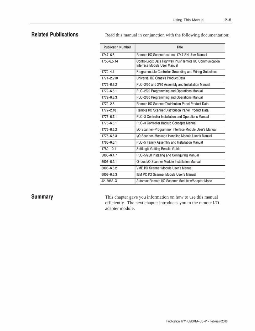
Read this manual in conjunction with the following documentation:
*137* !(&22*5 (&7 23 =! "6*5 &28&0
= 3275303,.; &7& .,-:&< 086 *137* 31182.(&7.3227*5+&(* 3)80* "6*5 &28&0
53,5&11&'0* 3275300*5 5382).2, &2) $.5.2, 8.)*0.2*6
"2.9*56&0 -&66.6 53)8(7 &7&
&2) 66*1'0< &2) 267&00&7.32 &28&0
53,5&11.2, &2) 4*5&7.326 &28&0
53,5&11.2, &2) 4*5&7.326 &28&0
*137* !(&22*5.675.'87.32 &2*0 53)8(7 &7&
*137* !(&22*5.675.'87.32 &2*0 53)8(7 &7&
3275300*5 267&00&7.32 &2) 4*5&7.326 &28&0
3275300*5 &(/84 32(*476 &28&0
!(&22*553,5&11*5 27*5+&(* 3)80* "6*56 &28&0
!(&22*5*66&,* &2)0.2, 3)80* "6*56 &28&0
&1.0< 66*1'0< &2) 267&00&7.32 &28&0
!3+73,.; *77.2, *68076 8.)*
267&00.2, &2) 32+.,85.2, &28&0
'86 !(&22*5 3)80* 267&00&7.32 &28&0
# !(&22*5 3)80* "6*56 &28&0
!(&22*5 3)80* "6*56 &28&0
% 8731&; *137* !(&22*5 3)80* :)&47*5 3)*
This chapter gave you information on how to use this manualefficiently. The next chapter introduces you to the remote I/Oadapter module.

Using This ManualP–6

9&0-'%8-32 >##! )&69%6=
,%48)6 &.)'8-:)7
3(90) )7'6-48-32 %2( )%896)7
%6(;%6) 31432)287
-%+2378-' 2(-'%8367
3(90) !;-8', 77)1&0-)7
-)0( $-6-2+ 61
!911%6=
,%48)6 &.)'8-:)7
3;)6 )59-6)1)287
3(90) 3'%8-32 %2( )=-2+
!)88-2+ 8,) 3(90) 32*-+96%8-32 09+7
!)88-2+ 8,) 3(90) !;-8',)7
((6)77 !;-8', 77)1&0= !
!;-8', 77)1&0= !
!)88-2+ 8,) ,%77-7 !;-8',)7
!)88-2+ 8,) %'/40%2) !;-8', 77)1&0=
!)88-2+ 8,) ,%77-7 3;)6 !9440= 32*-+96%8-32 09+
$-6-2+ 8,) -)0( $-6-2+ 61
278%00-2+ 8,) ")61-2%836
314%8-&-0-8= 3* )138) 63(9'87 ;-8,<8)2()( 3() 91&)67
3(90) 278%00%8-32
!911%6=
,%48)6 &.)'8-:)7
%6(;%6) ((6)77-2+
>!038 ((6)77-2+
3(90) 31&-2%8-327
#7-2+ !8%2(%6(>()27-8= 43-28 3(90)7
#7-2+ -+,>()27-8= 43-28 3(90)7
()28-*=-2+ 63947
3140)1)28%6= ;-8, >!038 ((6)77-2+
3(90) 0%')1)28 ;-8, >7038 ((6)77-2+
>!038 ((6)77-2+
()28-*=-2+ 63947
3(90) 0%')1)28 ;-8, >7038 ((6)77-2+
77-+2-2+ %'/ 91&)67 ;-8, >!038 ((6)77-2+
> !038 ((6)77-2+
Table of Contents

Table of Contents&"
3!+(" 2(.- 9 $!03 07
11(&-(-& "* 3,!$01 5(2' 91+.2 ##0$11(-&
.,/+$,$-2 07 5(2' 9+.2 ##0$11(-&
.#3+$ + "$,$-2 5(2' 91+.2 ##0$11(-&
(6(-& -# 9+.2 ##0$11(-& (- -#(4(#3 + ' 11(1
""$/2 !+$ ' 11(1 .,!(- 2(.-1
' 11(1 # /2$0 .#3+$ .,!(- 2(.-1
3,, 07
#&$
' /2$0 !)$"2(4$1
0.3!+$1'..2(-& (2' 2'$ -#(" 2.0 (&'21
32.".-%(&30$
3,, 07
##!*
/$"(%(" 2(.-1
##!*
$22(-&1 %.0 -# $0($1 -# $,.2$ # /2$01
##!*
(%%$0$-"$1 $25$$- 9 $0($1 -# $,.2$ # /2$0.#3+$1
##!*
3$12(.-1 -# -15$01
##!*
8 0#.31 ." 2(.- //0.4 +
$"'%""&!
#&"!%
&&!% "$ !
$%
! "& #&$%
$!% &)!
, $%
! "& #&$
"'%
'%&"!% ! !%)$%
+$"'% "&"!
##$"(

This chapter describes the cat. no. 1771-ASB, series E remote I/Oadapter module:
module description and features hardware components
The remote I/O adapter module serves as an interface betweenremote I/O modules and programmable controllers. The remote I/Oadapter:
• transmits data up to 10,000 cable-feet (at 57.6K baud)
• provides faster backplane scanning and data transmission up 2500cable-feet at 230.4K baud
• receives/sends data from/to the I/O scanner in serial form
• reads/writes data from/to the input modules in parallel form
• reads/writes data from/to the output modules in parallel form
• supports any mix of I/O (4, 6, 8, 16 or 32 points)
• supports three methods of I/O addressing; 1/2-slot, 1-slot and2-slot
• checks I/O configuration on power-up to verify I/O moduleplacement
• scans all slots in the chassis, or all but the last four slots, allowingimproved scan time and I/O image space savings. Slot powersupplies can be used in the last quarter of the rack without usingI/O space.
• can emulate series B adapters, providing system response similarto the 1771-ASB series B. This allows use of 1771-S4A and -S4Bscanners which require slower response for proper operation.
• has enhanced diagnostic indicators for easier troubleshooting.

1–2 Introducing the Remote I/O Adapter Module
/'%.%*) !,/,1
The remote I/O adapter module consists of four major components:
diagnostic indicators module switch assemblies field wiring arm
!" " !
Diagnostic indicators are located on the front panel of the adaptermodule (Figure 1.1). They show both normal operation and errorconditions in your remote I/O system. The indicators are:
• ACTIVE (green)• ADAPTER FAULT (red)• I/O RACK FAULT (red)
A complete description of these indicators and how to use them fortroubleshooting is explained in chapter 4.
#
" " # " !
%#)*-.%) %.*,-
0%.$
*)"%#/,.%*)/(+!,- -!! )*.!
%!' %,%)#,(
2
0%.$
*)"%#/,.%*)/(+!,- -!! )*.!
*)"%#/,.%*) &/(+!,- (1 ! %) !%.$!, +*-%.%*) !+!) %)# /+*) +,* /.%*) .!
$ "!

1–3Introducing the Remote I/O Adapter Module
You must set two switch assemblies to configure your adaptermodule. Figure 1.2 shows the location of the switches.
The S1 Assembly is used to select:
• the I/O rack number• the first I/O group number• I/O scanner communication with or without complementary
I/O (for PLC-2 family processors)
The S2 Switch Assembly selects:
• a specific baud rate based on the maximum I/O chassisdistance
• I/O scanner communication with or without complementaryI/O (for PLC-2 family processors)
• scan - processor will scan all slots in the chassis, or all but thelast four slots in the chassis
• link response - establishes series B emulation response timerequired for compatibility with PLC-2 and PLC-3 scanners.
The field wiring arm (cat. no. 1771-WB) provides connection pointsfor:
• I/O communication cables• a user-supplied I/O chassis restart pushbutton
The field wiring arm (Figure 1.1) pivots on the front of the chassis toconnect with the module’s printed circuit board. This feature allowsyou to remove the adapter module without disconnecting the systemwiring.

1–4 Introducing the Remote I/O Adapter Module
In this chapter we discussed the functions and hardware componentsof the Remote I/O Adapter Module.

&%! #&#(
This chapter describes the procedures for installing your remote I/Oadapter module. These include:
• power requirements
• module location and keying
• setting configuration plugs
• setting the module switches
• setting the I/O chassis switches (backplane and
• setting the I/O chassis power supply configuration plug
• wiring the field wiring arm
• installing the terminator resistor
• compatibility of products
• installing the module
The remote I/O adapter module requires a backplane current of 1.0Aat 5V dc. Remember to add this amount to other currentrequirements for your remote I/O chassis.
The remote I/O adapter module must be installed in the leftmost slotof the I/O chassis.
The I/O chassis backplane connectors are keyed to accept only onetype of module. This prevents accidental insertion of other modulesin the wrong module slot. Key the backplane connectors (Figure 2.1)for the adapter module as follows:
• upper connector: between 54 and 56• lower connector: between 16 and 18
#
$#% ( $ %' &""# ! %!# ) !'# ! %!# )
""# ! %!#
!'# ! %!#
( $
!
"
#

2–2 Installing Your Module
*" ) %$ '*'+
You need to set configuration plugs on the remote I/O adaptermodule to use 32-point I/O modules, . You access the plugs throughthe access hole on the left side of the module (Figure 2.2). Each plugis inserted on two pins of a three-pin connector. Thermocouple InputModules (Cat. No. 1771-IX and -IY) are not compatible with32-point I/O modules.
%( ) %$ "" !*#&'(%$ ) ") & $( ,
%$ *') %$ !*#&'( #+ $ )' &%( ) %$ &$ $ *&%$ &'%*) %$ )
When you set the configuration plugs in the leftposition, you can use 32-point I/O modules and anyaddressing method, but you cannot use Cat. No.1771-IX or 1771-IY modules. When you set these plugsin the right position, you can use 1771-IX and 1771-IYmodules and any addressing method, but you cannotuse 32-point I/O modules. If the plugs are setincorrectly, addressing errors will occur.
If you need to use a thermocouple module and 32-point I/O modulesin the same remote chassis, use the 1771-IXEThermocouple/Millivolt Module (Cat. No. 1771-IXE).
Set switch assemblies S1 and S2 (Figure 2.3) with a blunt, pointedinstrument such as a ball-point pen. Do not use a pencil; the leadcould break off and jam the switch.
This publication describes switches as being either on or off. Thewords ON and OFF should be printed on the switch assemblies. If aswitch assembly has the word OPEN printed on it, the word OPENcorresponds to OFF.

2–3Installing Your Module
$!
%# ""& # "
!"" %# ""&
You use this switch assembly to select:
• the I/O rack number• the first I/O group number• primary/complementary – I/O scanner communication with
or without complementary I/O (for PLC-2 and PLC-5 familyprocessors)
%# ""&
You use this switch assembly to select:
• baud – a specific baud rate based on the maximum I/O chassisdistance
• primary/complementary – I/O scanner communication withor without complementary I/O (for PLC-2 family processors)
• scan - select whether the processor will scan all slots in thechassis, or all but the last four slots in the chassis

2–4 Installing Your Module
-%$,$(' *-*0
link response - unrestricted or series B emulation.Certain scanner modules with multiple communication portsrequire a delay in the link turnaround time to allow the centralprocessing unit (CPU) in the scanner sufficient time to serviceall communication ports. Without this delay, some incominginformation may be missed while the scanner is servicinganother port. This results in multiple communication retries.To provide the necessary delay, set the link response switch(position 5, switch S2) to the ON position.
Scanner modules which require a delay are:
1 1
1
1 1
1
1 1
1 1
• noise immunity – enables backplane retries to occur whennoise is detected on the I/O rack backplane. This feature isenabled when the switch is off. Do not use this switch positionas a substitute for improper noise suppression.
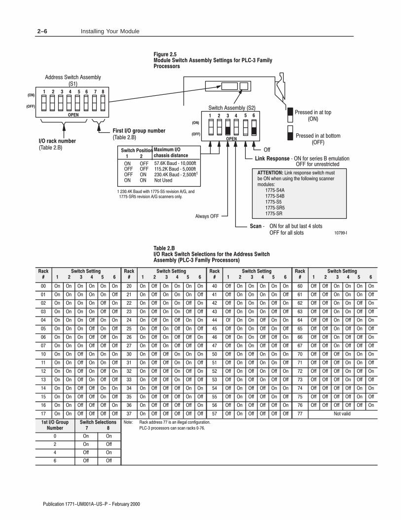
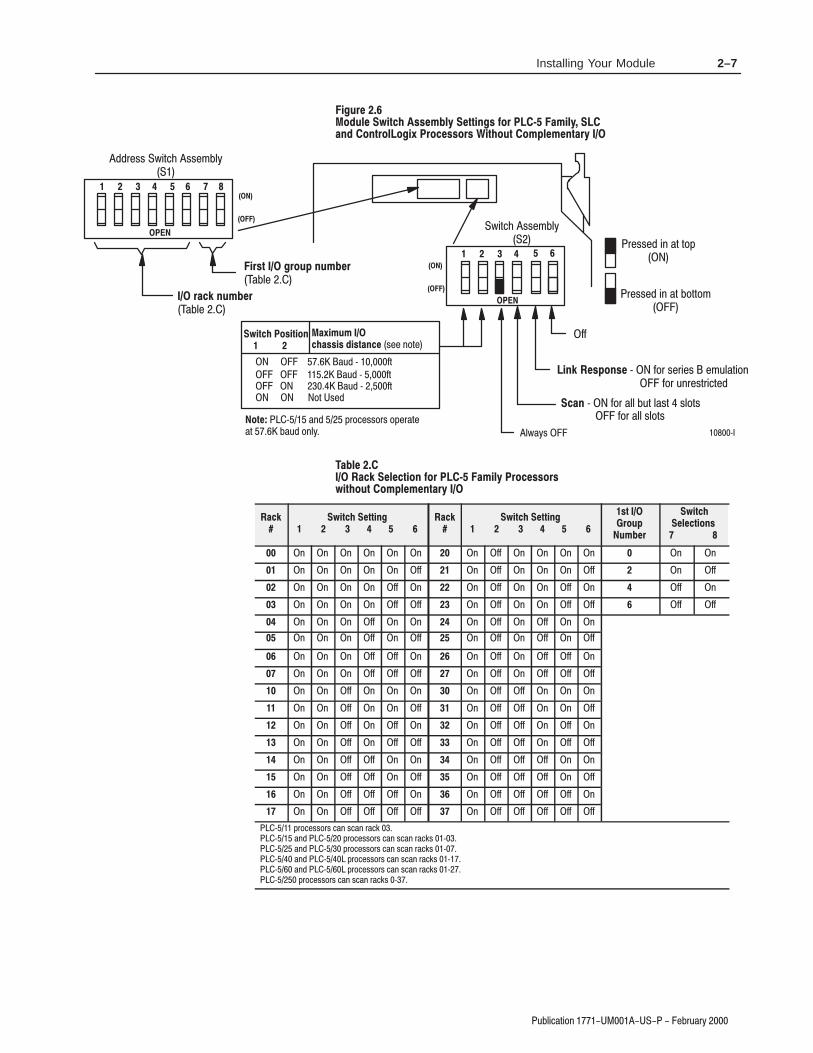
Refer to the Table below for Figure and page numbers of switchsettings for each processor family.
1 !&$%0 )*( ++(* $"-* )"
1 !&$%0 )*( ++(* $"-* )"
1 !&$%0 ' (',*(%("$/ )*( ++(*+.$,#(-, (&)% & ',*0
$"-* )"
1 !&$%0 ' (',*(%("$/ )*( ++(* .$,#(&)% & ',*0
$"-* )"

2–5Installing Your Module
3"+)#!2).- %"03!05
&$0-"
+!0(" 1&/ % ..")(3 "//&*$. #+- 4 )&(3
-+ "..+-.
&-./ $-+0, *0)"-
!"+%
- ' *0)"-
!"+%
$$0%11 4)2#( 11%,"+5
4)2#( 11%,"+5
6 !+4!51 6 4)2(.32 #.,/+%,%-2!05 6 !+4!51
6 4)2( #.,/+%,%-2!05 6
6 0),!05 #(!11)1 6 .,/+%,%-2!05 #(!11)1
0%11%$ )- !2 2./
0%11%$ )- !2 ".22.,
2&)0)
%..&. !&./* "
6 !+4!51 6 4)2(.32 #.,/+%,%-2!05
6 !+4!51
6 4)2( #.,/+%,%-2!05 6
6 0),!05 #(!11)1 6 .,/+%,%-2!05 #(!11)1
+4!51
&*' ".,+*." 6 &.0 1%0)%1 %,3+!2).-
* 6 &.0 !++ "32 +!12 1+.21 &.0 !++ 1+.21
&.0 3-0%120)#2%$
1&/ % +.&/&+*
!3$ 6 &2
!3$ 6 &2.2 1%$.2 1%$
6
)-* 0%1/.-1% 14)2#( ,312"% 4(%- 31)-' 2(% &.++.4)-' 1#!--%0,.$3+%1
6
&&
("
' 0)"- *! &-./ -+0, 1&/ % "(" /&+*. #+-
/%" !!-".. 1&/ % ..")(3 4 )&(3
-+ "..+-.
'
0)"-
1&/ % "(" /&+*.
&-./ -+0,
0)"-
1&/ % "(" /&+*.
- - - - -
- - && - &&
- && - && -
- && && && &&
&& - -
&& - &&
&& && -
2–6 Installing Your Module
4#,*$"3*/. !! "17
'%1.#
,"1)# 2'0!& //#* )4 #00'+%/ $,. 5 *')4
.,!#//,./
'./0 %.,1- +1* #.
"#,& .!( +1* #.
"#,&
%%1&22 6*3$) 22&-#,7
6*3$) 22&-#,7 1&22&% *. "3 3/0
1&22&% *. "3 #/33/-
2'0!& ,/'0',+
"4% 8 '3 "4% 8 '3
/3 !2&%
3'*1*
!&//'/ "'/0+!#'+( #/-,+/# 8 '/1 2&1*&2 &-4,"3*/.
!+ 8 '/1 ",, #43 ,"23 2,/32 '/1 ",, 2,/32
'/1 4.1&231*$3&%
,6"72
8
*.+ 1&20/.2& 26*3$) -423#& 6)&. 42*.( 3)& '/,,/6*.( 2$"..&1-/%4,&2
8 8 8 8 8
"4% 8 '3
"4% 6*3) 8 1&5*2*/. ".% 8 1&5*2*/. 2$"..&12 /.,7
''
)#
!( 2'0!& #)#!0',+/ $,. 0&# "".#// 2'0!&
//#* )4 5 *')4 .,!#//,./
!(
2'0!& #00'+%
!(
2'0!& #00'+%
!(
2'0!& #00'+%
!(
2'0!& #00'+%
. . . . . . . '' . . . . '' . . . . . '' '' . . . .
. . . . . '' . '' . . . '' '' . . . . '' '' '' . . . ''
. . . . '' . . '' . . '' . '' . . . '' . '' '' . . '' .
. . . . '' '' . '' . . '' '' '' . . . '' '' '' '' . . '' ''
. . . '' . . . '' . '' . . ' . . '' . . '' '' . '' . .
. . . '' . '' . '' . '' . '' '' . . '' . '' '' '' . '' . ''
. . . '' '' . . '' . '' '' . '' . . '' '' . '' '' . '' '' .
. . . '' '' '' . '' . '' '' '' '' . . '' '' '' '' '' . '' '' ''
. . '' . . . . '' '' . . . '' . '' . . . '' '' '' . . .
. . '' . . '' . '' '' . . '' '' . '' . . '' '' '' '' . . ''
. . '' . '' . . '' '' . '' . '' . '' . '' . '' '' '' . '' .
. . '' . '' '' . '' '' . '' '' '' . '' . '' '' '' '' '' . '' ''
. . '' '' . . . '' '' '' . . '' . '' '' . . '' '' '' '' . .
. . '' '' . '' . '' '' '' . '' '' . '' '' . '' '' '' '' '' . ''
. . '' '' '' . . '' '' '' '' . '' . '' '' '' . '' '' '' '' '' .
. . '' '' '' '' . '' '' '' '' '' '' . '' '' '' '' /3 5",*%
/0 .,1-
1* #.
2'0!& #)#!0',+/
/3& "$+ "%%1&22 *2 ". *,,&(", $/.'*(41"3*/.
8 01/$&22/12 $". 2$". 1"$+2 8
. .
. ''
'' .
'' ''
2–7Installing Your Module
0 (&!/&+* # -0-2
)'30%
.$3+% 4)2#( 11%,"+6 %22)-'1 &.0 7 !,)+6
!-$ .-20.+.')5 0.#%11.01 )2(.32 .,/+%,%-2!06
)012 '0.3/ -3,"%0
(#
0!#* -3,"%0
(#
""-#.. 1&/!% ..#) (2
1&/!% ..#) (2
)-* %1/.-1% 3 $+- .#-&#. #)0(/&+* $+- 0*-#./-&!/#"
#!- 3 $+- (( 0/ (./ .(+/. $+- (( .(+/.
(12. 3
4)2#( .1)2).-
0" 3 $/
0" 3 $/
+/ .#"
!5),3,
#(!11)1 $)12!-#% .## *+/#
0" 3 $/
.2% 3 *" ,-+!#..+-. +,#-/#/ 0" +*(2
-#..#" &* / /+,
-#..#" &* / +//+)
$$
!"+%
!#* %+%#2).- &.0 7 !,)+6 0.#%11.01
4)2(.32 .,/+%,%-2!06
!#*
4)2#( %22)-'
!#*
4)2#( %22)-'
12
0.3/
3,"%0
4)2#(
%+%#2).-1
* * * * * * * $$ * * * * * *
* * * * * $$ * $$ * * * $$ * $$
* * * * $$ * * $$ * * $$ * $$ *
* * * * $$ $$ * $$ * * $$ $$ $$ $$
* * * $$ * * * $$ * $$ * *
* * * $$ * $$ * $$ * $$ * $$
* * * $$ $$ * * $$ * $$ $$ *
* * * $$ $$ $$ * $$ * $$ $$ $$
* * $$ * * * * $$ $$ * * *
* * $$ * * $$ * $$ $$ * * $$
* * $$ * $$ * * $$ $$ * $$ *
* * $$ * $$ $$ * $$ $$ * $$ $$
* * $$ $$ * * * $$ $$ $$ * *
* * $$ $$ * $$ * $$ $$ $$ * $$
* * $$ $$ $$ * * $$ $$ $$ $$ *
* * $$ $$ $$ $$ * $$ $$ $$ $$ $$
3 ,-+!#..+-. !* .!* -!' 3 *" 3 ,-+!#..+-. !* .!* -!'. 33 *" 3 ,-+!#..+-. !* .!* -!'. 33 *" 3 ,-+!#..+-. !* .!* -!'. 33 *" 3 ,-+!#..+-. !* .!* -!'. 33 ,-+!#..+-. !* .!* -!'. 3

2–8 Installing Your Module
1!)'" 0',+ $!.1 .3
*(41&
/%4,& 5*3$) 22&-#,7 &33*.(2 '/1 8 "-*,7
".% /.31/,/(*6 1/$&22/12 !*3) /-0,&-&.3"17
*123 (1/40 .4-#&1
!)$
1"$+ .4-#&1
!)$
##.$// 2'0"& //$*!)3
2'0"& //$*!)3 .$//$# '+ 0 0,-
.$//$# '+ 0 !,00,*
)2 3/
4 .'* .3 "& //'/ 4 ,*-)$*$+0 .3 "& //'/
4 .'* .3 "& //'/ 4 ,*-)$*$+0 .3 "& //'/
*.+ &20/.2& 4 %,. /$.'$/ $*1) 0',+
$". 4 %,. )) !10 ) /0 /),0/ %,. )) /),0/
%,. 1+.$/0.'"0$#
4
5*3$) /2*3*/.
1# 4 %0
1# 4 %0
,0 /$#
"6*-4-
$)"22*2 %*23".$& /$$ +,0$
1# 4 %0
/3& 4 +# -.,"$//,./ ,-$. 0$ 0 ! 1# ,+)3
%%
"#,&
"$+ &,&$3*/. '/1 8 "-*,7 1/$&22/12 5*3)
/-0,&-&.3"17
"$+
5*3$)
23 1/40
4-#&1
5*3$) &,&$3*/.2
+ + + + + %% + +
+ + + + %% + + %%
+ + + + %% %% %% +
%% %%
+ + + %% + +
+ + + %% + %%
+ + + %% %% +
+ + + %% %% %%
$$ +,0$ !$),2
/3& 4 " + /" + . "( 4 4 4 4 " + /" + . "(/ 4

2–9Installing Your Module
,$"+"'& ),)/
After setting the adapter module switch assemblies, you must also
• set the I/O chassis backplane switches
,,#'! ," $)%' .#," ++&%/
The backplane switch assembly is located on the backplane of theI/O chassis. You use it to select:
• the last state of all outputs
• the processor restart lockout feature
• 1/2-, 1- or 2-slot addressing
• the last chassis in the I/O system (for PLC-2 family processors)
Refer to the table below for backplane switch setting illustrations forthe various processors.
(* *(++(* * ,(
1 " ,) (
1 " ,) (
1 " ,) (
1 )%'+ '&" ,)+"'& " ,) (
1 " ,) (
#!-*
"++#+ $)%' .#," ++&%/ ,,#'!+ (*
&(, ),* (-% #' 0 &#%/ *(++(* /+,&
*(++(* +,*, ($(-, 0
!& ()'**') & )*+)+ !**"*!& !**"* %,*+ )*+)+ + +! !**"*
*++#'! .#," 0
1 1*$'+ )**"& *$+ 1 1*$'+ )**"& *$+
+, ,, .#," 0
!& ',+(,+* ' +!"* !**"* )%"&"& $*+ *++!& ',+(,+* ' +!"* !**"* )&) "0 .!& ,$+ "* ++
$./*
+, "++#+ .#," 0
1 !**"* '* &'+ '&+"& +! !" !*+ &,%) )',( ') +! **'"+ )# &,%) 1 !**"* '* '&+"& +! !" !*+ &,%) )',( ') +! **'"+ )# &,%)
/', !- '&$/ ()"%)/ !**"* *+ +!"**."+! +' /', !- '+! ()"%)/ & '%($%&+)/!**"* *+ +! ()"%)/ !**"* +' & +!'%($%&+)/ !**"* +'
+ *."+! +' +! ('*"+"'&+' &) "0 ',+(,+* .") +' +!"* !**"* .!& ,$+ "* ++ *."+! "* *+ +' +! ('*"+"'& ',+(,+* '&&+ +' +!"* !**"* )%"&"& +!") $*+ *++ .!& ,$+ ',)* & %!"&%'+"'& %/ '&+"&, +) ,$+ ++"'&
$./*
,,#'! ," "++#+
.#,"+

2–10 Installing Your Module
.&$-$)( +.+1
%#/,!
$--%- &+')! 0%.$ --!('1 !..%)#- "*,
!(*.! +.!, * /'! %) 2 (%'1 ,*!--*, 1-.!(
,*!--*, !-.,. *&*/. 2
# ( *+) ,,)+ ( + ,-+- #,,$,# ( #,,$, '.,- + ,-+- - -# #,,$,
-. ..! 0%.$ 2
# ( ).-*.-, )! -#$, #,,$, + '$( $( &,- ,-- # ( ).-*.-, )! -#$, #,,$, + ( +"$2 0# ( !.&- $, - -
&01,
3
- ,0$-# -) -# *),$-$)(-) ( +"$2 ).-*.-, 0$+ -) -#$, #,,$, 0# ( !.&- $, - - ! ,0$-# $, , - -) -# *),$-$)( ).-*.-, )(( - -) -#$, #,,$, + '$($( -# $+ &,- ,-- 0# ( !.&- ).+, ( '#$( ')-$)( '1 )(-$(. !- + !.&- - -$)(
). , & - 3,&)- + ,,$(" ). , & - 3,&)- + ,,$(" ). , & - 3,&)- + ,,$(" )- &&)0
+ ,,$(" 0$-# ,
3 #,,$, $( 3 %.* 3 ! (1 3 #,,$, )(-$(,,-+-$(" "+).* 0$-# 3,&)- + ,,$("( -# 3 $, )(!$".+ $( %.* ') 3 && )-# + -$' ,
%#/,!
$--%- &+')! 0%.$ --!('1 !..%)#- "*,
!(*.! +.!, * /'! %) 2 (%'1 ,*!--*, 1-.!(
,*!--*, !-.,. *&*/. 2
# ( *+) ,,)+ ( + ,-+- #,,$,# ( #,,$, '.,- + ,-+- - -# #,,$,
-. ..! 0%.$ 2
# ( ).-*.-, )! -#$, #,,$, + '$( $( &,- ,-- # ( ).-*.-, )! -#$, #,,$, + ( +"$2 0# ( !.&- $, - -
&01,
3
- ,0$-# -) -# *),$-$)(-) ( +"$2 ).-*.-, 0$+ -) -#$, #,,$, 0# ( !.&- $, - - ! ,0$-# $, , - -) -# *),$-$)( ).-*.-, )(( - -) -#$, #,,$, + '$($( -# $+ &,- ,-- 0# ( !.&- ).+, ( '#$( ')-$)( '1 )(-$(. !- + !.&- - -$)(
). , & - 3,&)- + ,,$(" ). , & - 3,&)- + ,,$(" ). , & - 3,&)- + ,,$(" )- &&)0
+ ,,$(" 0$-# ,
-. $--%- 0%.$ 2
3 #,,$, ) , ()- )(-$( -# #$"# ,- (.'3 + "+).* !)+ -# ,,)$- +% (.' + 3 #,,$, ) , )(-$( -# #$"# ,- (.' + "+).* !)+ -# ,,)$- +% (.' +
! 1). #/ )(&1 *+$'+1 #,,$, , - -#$,,0$-# -) ! 1). #/ )-# *+$'+1 ( )'*& ' (-+1#,,$, , - -# *+$'+1 #,,$, -) ( -# )'*& ' (-+1 #,,$, -)

2–11Installing Your Module
)! ( $# &)&+
%#/,!
$--%- &+')! 0%.$ --!('2 !..%)#- "*,
!(*.! +.!, * /'! %) 3 (%'2 )
*).,*'*#%1 ,*!--*, 2-.!(- %) !(*.! *)"%#/,.%*)
,*!--*, !-.,. *&*/. 3
# %&$''$& # &'(&( '' '# '' ' ")'( &'(&( ( ( '' '
-. ..! 0%.$ 3
# $)(%)(' $ ( ' '' ' &" # # !'( '((# $)(%)(' $ ( ' '' ' & #& ,*# )!( ' ((
!*+'
-
$) '!( -'!$( &'' # $) '!( -'!$( &'' # $) '!( -'!$( &'' # $( !!$*
&'' # * ('
!*+'
'* ( ' '( ($ (
%$' ( $# $)(%)(' $##( ($ ( ' '' '&" # # ( & !'( '(( *# )!( $)&'# " # "$( $# "+ $#( #) (& )!((( $# &$""# (( +$) '( '* ( ($ ( %$' ( $# ($ #& , $)(%)(' * &($ ( ' '' ' *# )!( ' ((
%#/,!
$--%- &+')! 0%.$ --!('2 !..%)#- "*,
!(*.! +.!, * /'! %) 3 ,*!--*, 2-.!(
,*!--*, !-.,. *&*/. 3
# %&$''$& # &'(&( '' '# '' ' ")'( &'(&( ( ( '' '
-. ..! 0%.$ 3
# $)(%)(' $ ( ' '' ' &" # # !'( '((# $)(%)(' $ ( ' '' ' & #& ,*# )!( ' ((
!*+'
-
$) '!( -'!$( &'' # $) '!( -'!$( &'' # $) '!( -'!$( &'' # $( !!$*
&'' # * ('
!*+'
( '* ( ($ ( %$' ( $#($ #& , $)(%)(' * & ($ ( ' '' '*# )!( ' (( '* ( ' '( ($ ( %$' ( $# $)(%)(' $##( ($ ( ' '' '&" # # ( & !'( '(( *# )!( $)&'# " # "$( $# "+ $#( #) (& )!((( $#

$,,%,)/!+ .**&1)("%#.+-%)(&.#
2–12 Installing Your Module
.&%-%)( !+.+1
You use the I/O chassis power-supply configuration plug (Figure2.13) to identify the type of power supply you use with your remotechassis. This configuration plug is located on the backplane of seriesB I/O chassis.
#
! !!! $ #% # " #
""!
! " " !!! # " # "
*)/!+ ,.**&1 ') .&! %(,-&&! %( $,,%,
2 *),%-%)(
!0-!+(& *)/!+ ,.**&1 %( 1).++!')-! ,1,-!'
2 *),%-%)(
The field wiring arm provides connection points for:
• I/O communication cables
• a user-supplied I/O chassis restart pushbutton
The wiring arm pivots on the front of the chassis to connect with themodule’s printed circuit board, allowing you to remove the adaptermodule without disconnecting the system wiring.
Connect input/output cables to the field wiring arm as shown inFigure 2.14.
"" " !!!
$ #%
# " #
"

2–13Installing Your Module
3"+)#!2).- %"03!04
#
" " $ !
)-%
()%+$
)-%
. #.--%#2).-
. #.--%#2).-
. #.--%#2).-
. #.--%#2).-
. #.--%#2).-
. #.--%#2).-
. #.--%#2).-
-
%2
%1%2 1%0 13//+)%$ 0!#* 0%12!02/31("322.-
++%-50!$+%4 !"+% #!2 -. 5
+3%
()%+$
+%!0
!"+%
. -.2 ,!*% #.--%#2).-1 2.2%0,)-!+1 2(0.3'( (%1% 2%0,)-!+1!0% #.--%#2%$ )-2%0-!++4 2. 2. !-$ 2. !-$ #!--.2 "% 31%$ &.0 !-4 .2(%0/30/.1%
%,.2% !"+%
!ATTENTION: Do not remove or insert the adaptermodule from the I/O chassis while system power is on.Otherwise, you may damage module circuitry.
Terminals 1 and 4, 2 and 5, and 3 and 6 are internally connected onthe module. If you use these terminals (4, 5, and 6) for connection ofadditional adapter modules, you disconnect the remaining adaptermodules in the series connection when you disconnect the remoteI/O adapter module wiring arm. If this is unsuitable for yourapplication, make your connections to terminals 1, 2, and 3 only.

2–14 Installing Your Module
! !"
If this is the last remote I/O adapter on the link, you must use aterminating resistor to terminate both ends of the remote I/O link(scanner end and last adapter end). Connect the terminator acrossterminals 1 (blue) and 3 (clear).
The size of the terminator is determined by the system configuration.Older configurations use a 150 ohm resistor at both ends. With newerproducts that can support it, you can use an 82 ohm terminator atboth ends. The 82 ohm terminators provide “extended node”capability which allows you to have up to 32 physical devices on theRIO link. (The number of logical racks capable of being addressedby the scanner is not affected.) This allows 1/4, 1/2 and 3/4 racks,Dataliners, Redipanels and Panelview devices to be attached to thelink.
!ATTENTION: Devices that are operating at 230.4KBaud must have 82 ohm terminators in place for properoperation.
Certain products are not compatible with the extended nodecapabilities obtained with the use of the 82 ohm terminator resistors.These products are listed below.
'! "!
#
# #
#
#
#
#
#
# #
#
#
! # #
#
! ! !
!!&
! "! $!
%! "

2–15Installing Your Module
Once you’ve determined the power requirements, keying, and wiringfor your adapter module, and have set the appropriate switchassemblies, you can use the following procedure to install it.
Refer to the Industrial Automation Wiring and Grounding Guidelinesfor Noise Immunity (publication 1770-4.1) for proper grounding andwiring methods to use when installing your module.
!ATTENTION: Remove system power beforeremoving or installing your module in the I/O chassis.Failure to observe this warning could damage modulecircuitry and injure people.
1. Remove power from the I/O chassis before inserting (orremoving) the module.
2. On chassis equipped with a chassis locking bar, pull thelocking-bar pins to release the locking bar and swing it up.
3. Insert the module into slot.
4. Place the module in the plastic tracks on the top and bottom ofthe leftmost slot. These slots guide the module into position.
5. Press firmly and evenly to seat the module in its backplaneconnectors.
!ATTENTION: Do not force the module into thebackplane connector. If you cannot seat the modulewith firm pressure, check the alignment and keying.Forcing the module can damage the backplaneconnector or the module.
6. Snap the chassis locking bar (or locking latch on earlier chassis)over the top of the module to secure it. Make sure the lockingpins on the locking bar are fully engaged.
Note: The chassis locking bar will not close if all modules arenot properly seated.
7. Swing field wiring arm up into place and press firmly until itlatches.
8. Reapply system power and check for proper operation.
In this chapter you learned how to install your adapter module.Chapter 3 tells you how to configure your module.

2–16 Installing Your Module

When you configure your remote I/O system, you must consider:
• how to address your I/O• what combination of I/O modules and I/O chassis you can use
These topics are discussed in this chapter.
Programmable controllers that use the 1771-ASB remote I/O adaptermodule can address their I/O in 2-slot, 1-slot or 1/2 slot I/O groups.These three addressing methods are referred to as 2-slot addressing,1-slot addressing and 1/2-slot addressing.
You select the addressing method with switch 5 and 6 in the I/Ochassis backplane switch assembly. You make this selection for eachchassis independently with only one method of addressing for eachchassis.
I/O groups are made up of I/O terminals (Figure 3.1). An I/O groupis an addressing unit that can contain up to 16 input terminals and 16output terminals. You select an I/O chassis to have either 2-slot,1-slot or 1/2-slot I/O groups.

3–2 Addressing Modes for Your Remote I/O
#" # $
%"
" %! & ! $ !%$ "# %$!%$
"#
# " !
# " # " !
# " # " # " !
%!" # %!" #
I/O racks are made up of I/O groups (Figure 3.1). An I/O rack is anaddressing unit that can contain up to eight I/O groups.
%"
& ! $ $ " %!#

3–3Addressing Modes for Your Remote I/O
! !"
Definition: The processor addresses two I/O module slots as one I/Ogroup.
Concept: Each physical 2-slot I/O group is represented by a word inthe input image table and a word in the output image table. Eachinput terminal corresponds to a bit in the input image table word andeach output terminal corresponds to a bit in the output image tableword.
The maximum number of bits available for one 2-slot I/O group is32: 16 bits in the input image table and 16 bits in the output imagetable. The type of module you install (either 8 or 16-point I/O)determines the number of bits in the words that are used.
You select 2-slot addressing by setting switches 5 and 6 of the I/Ochassis backplane switch assembly to the OFF position.
" !
The combination of I/O modules you can use depends on theaddressing method and I/O chassis you select.
Table 3.A lists acceptable I/O module combinations with 2-slotaddressing.
" ! ! # !
" ! "
! !
"! "!"!
# ! !
# ! ! !
# ! ! ! !
# ! ! ! !
# ! ! !
!
" # ! ! ! !
# # ! ! !
# ! # ! ! !
#!

3–4 Addressing Modes for Your Remote I/O
( '#" %(%*
#"
Standard-density I/O modules provide eight input terminals or eightoutput terminals. Figure 3.3 illustrates the 2-slot I/O group conceptwith two 8-point input modules. Figure 3.4 shows an 8-point inputmodule and an 8-point output module in a 2-slot I/O group.
! #
" $ ( ' %! " &
" $ ( ' %! " &
( '$ ( ' ! ' ) # % # %% &$ # " " '# ' %# ( $
( " ( &
" $ ( ' ! ' ) # % # %% &$ # " " '# ' %# ( $
+& #' %#($

3–5Addressing Modes for Your Remote I/O
( '#" %(%*
%"
'! $ !%$ %$!%$ %# # $ $# $
!%$ " $ $# $ %$!%$
"
" $ ( ' %! " &
( '$ ( ' %! " &
( '$ ( ' ! ' ) # % # %% &$ # " " '# ' %# ( $
( " ( &
" $ ( ' ! ' ) # % # %% &$ # " " '# ' %# ( $
( '$ ( ' '& ( &
" $ ( ' '& ( & ) *&
+& #' %#($
# '#$& ! $ %#
16-point I/O modules provide 16 input terminals or 16 outputterminals. 16-point I/O modules use a full word in the input oroutput image table when they are addressed as a 2-slot I/O group(Figure 3.5). Two 16-point modules (one input and one output) canbe used in a 2-slot I/O group.

3–6 Addressing Modes for Your Remote I/O
( '#" %(%*
( '$ ( ' ! ' ) # % # %% &$ # " " '# ' %# ( $
" $ ( ' ! ' ) # % # %% &$ # " " '# ' %# ( $
" $ ( ' %! " &
( '$ ( ' %! " &
+& #' %#($
Because these modules use a full word in the image table, the onlytype of module you can use in a 2-slot I/O group with a 16-pointmodule is one that performs the opposite (complementary) function;an input module complements an output module and vice-versa.
You can use an 8-point module with a 16-point module in a 2-slotgroup; it must perform the opposite function. However, eight bits inthe I/O image table are unused.

3–7Addressing Modes for Your Remote I/O
3"+)#!2).- %"03!06
You identify your I/O groups in one of three ways, depending on theaddressing method and I/O chassis you use. Refer to:
• Figure 3.6 for 2-slot addressing when using series A I/O chassis.
• Figure 3.7 for 2-slot addressing when using series B I/O chassis.
• Figure 3.13 for 1-slot addressing when using series B I/O chassis.
-/32%0, )-! +1
32/32%0, )-! +1
1+. 2 0.3/
6/% .& ,.$3+%
-/32
32/32
!#* 3,"%0
(61)#!+ $$0%11
.$3+%%0,)-!+3,"%0
0.3/3,"%0
-/32 ), !'% 2!" +% 4.0$ #.00%1/.-$ )-' 2. 2(% '0.3/
%&2+.2
)'(2+.2
7 7
.$3+%%0,)-!+3,"%0
6/% .& ,.$3+%
-/32
32/32
!#* 3,"%0
0.3/3,"%0
5!,/+% 1)-' 0.3/ ! 1!,/+% /(61)#!+ !$$0%114)2( )21 #.00%1/.-$)-' $!2! 2!"+% !$$0%11 )1
7

3–8 Addressing Modes for Your Remote I/O
5$-+%#4+0/ "" '$25#28
!81' 0( .0&5-'
/154
54154
#%, 5.$'2
*83+%#- &&2'33
0&5-'!'2.+/#-5.$'2
20515.$'2
/154 +. #)' 4#$ -' 602& %022'310/& +/) 40 4*' )2051
'(4 -04
+)*4 -04
0&5-'!'2.+/#-5.$'2
!81' 0( .0&5-'
/154
54154
#%, 5.$'2
20515.$'2
7#.1-' "3+/) 2051 #/& 910+/4 .0&5-'3 # 3#.1-'1*83+%#- #&&2'33 6+4* +43 %022'310/&+/) # 4#$-' #&&2'33 +3
/154!'2. +/# -3
54154!'2. +/# -3
3-0 4 2051
9
9
9
9
5-'3 (02 .0&5-' 4'2.+/#- 10+/4 #33+)/.'/43 #2'
4#/& &'/3+48 &+3%2'4' .0&5-' +/ 4*' -'(4 3-04*#3 4'2.+/#-3 /5.$'2'& 9 #2, 401 0/-8
4#/& &'/3+48 &+3%2'4' .0&5-' +/ 4*' 2+)*4 3-04*#3 4'2.+/#-3 /5.$'2'& 9 #2, $0440. 0/-8
+)* &'/3+48 910+/4 &+3%2'4' .0&5-' +/ '+4*'2 3-04*#3 4'2.+/#-3 /5.$'2'& 9 #/& 9
9

3–9Addressing Modes for Your Remote I/O
2!*(" 1(-, $!/2 /5
Some processors support a complementary I/O configuration. Referto the user manual for your processor to see if it supports this type ofconfiguration.
You configure complementary I/O by duplicating an I/O racknumber of one I/O chassis (primary) in another I/O chassis(complementary), I/O group for I/O group. The I/O modules in thecomplementary chassis perform the opposite function of thecorresponding modules in the primary chassis.
With 2-slot addressing you install, as a pair, the same type of 8-pointI/O module in an I/O group of the primary chassis. You install, as apair, the opposite type of 8-point I/O module in the correspondingI/O group of the complimentary chassis.
For example, with an I/O chassis set for 2-slot addressing, place two8-point input modules in I/O group 0 of the primary chassis. In I/Ogroup 0 of the complementary chassis, place two 8-point outputmodules (Figure 3.8). Use the same type of 8-point I/O modules inboth slots of a single I/O group.
!
-2! *$0*- 1
-2!*$0 *- 1
4 + . *$
4 + . *$
/ (+ /5 0 *- 1 ' 0 0 (0
/- 2 . 2+ ! $ /
-+ . *$+ $ , 1 /5 0 *- 1 ' 0 0 (0
/ (+ /5 0 *- 1 ' 0 0 (0
/- 2 . 2+ ! $ /
-+ . *$ + $ , 1 /5 ' 0 0 (0 - 1
**- 3 $ # 4 " $ . 1 %- / 2 1. 2 1
,.21 -#2 *$
21.21 -#2 *$
*-") 1/ ,0%$/ -#2 *$ 21.21 + -#2 *$0 20$ 1'$ 0 +$ -21.21 (+ &$ 1 ! *$ ! (10
, !$ .- (, 1 (,.21 -/ -2 1.21 + -#2 *$ - / 0 (,& *$0*- 1 ! *-") 1/ ,0%$/ + -#2 *$
201 !$ $+.15 (% "-//$0.-,# (,& ./(+ /5 0*- 1 (0 ! *-") 1/ ,0%$ / + -#2 *$
2 1. 2 10 (, 1' $ " -+ . *$ + $ , 1 /5 " ' 0 0 (0 2 0 $ 1' $ 0 + $ ! (10 (, 1' $ - 2 1. 2 1 (+ & $ 1 ! *$ 01' $ - 2 1. 2 10 (, 1' $ . / (+ /5 " ' 0 0 (0
!

3–10 Addressing Modes for Your Remote I/O
0(& /&+* "-0-3
Follow these guidelines when configuring your remote system withcomplementary I/O chassis:
• Assign the complementary I/O rack number to a chassis of equalor smaller size than the primary chassis.
• If the complementary chassis is smaller than the primary one, setthe last chassis switch on the complementary chassis to the ONposition, unless the adapter is in the faulted I/O search mode.
• For PLC-2 family processors:
• Connect the complementary chassis to the same scannerchannel as the primary chassis.
• Connect the complementary chassis to the remote trunkline asthough they were additional primary chassis.
• For PLC-3 processors, connect the complementary chassis to adifferent scanner channel as the primary chassis.
• Assign the same beginning I/O group number to both I/O racks.
• You cannot configure complementary I/O in a chassis that uses acombination of 2-slot addressing and 16-point I/O.
• You cannot use 32-point I/O modules in a complementary I/Oconfiguration when you select 2-slot or 1-slot addressing.
• You can place an output module opposite another outputmodule; they reflect the same bits in the output image table.
• Do not place an input module opposite an input module.
You can use the following modules in either primary orcomplementary I/O chassis opposite any type of module:
4 4 4 *(+$ *,0/ 2,*!"- ..")(3
4 *(+$ 0/,0/ 2,*!"- ..")(3
4 %"-)+ +0,(" *,0/ 2,*!"- +!0(" ..")(3
4 "-1+ * +!"- ""! ' 2,*!"- ..")(3
4 +))0*& /&+* !,/"- +!0("
4 +))0*& /&+* +*/-+(("- +!0("
4 4 )&(344 */"-# " +!0("
4 0(." 0/,0/ 2,*!"- ..")(3
4 &"- ,/& . +*1"-/"- +!0("

3–11Addressing Modes for Your Remote I/O
2!*(" 1(-, $!/2 /5
!
Figure 3.9 shows possible module placement when configuringcomplementary I/O with 2-slot addressing.
!
-2! *$0*- 1
-2!*$0 *- 1
4 + . *$
4 + . *$
/ (+ /5 0 *- 1 ' 0 0 (0
/- 2 . 2+ ! $ /
-+ . *$ + $ , 1 /5 0 *- 1 ' 0 0 (0
/ (+ /5 0 *- 1 ' 0 0 (0
/- 2 . 2+ ! $ /
-+ . *$ + $ , 1 /5 ' 0 0 (0 - 1
**- 3 $ # 4 " $ . 1 %- / 2 1. 2 1
,.2 1 -#2 *$
21.21 -#2 *$ *-") 1/ ,0%$/ -#2 *$
21.21 + -#2 *$0 20$ 1'$ 0 +$ -21.21 (+ &$ 1 ! *$ ! (10
, !$ .- (, 1 (,.21 -/ -21.21 + -#2 *$ -/ 0 (,& *$0*- 1 ! *-") 1/ ,0 %$/ + -#2 *$
201 !$ $+.15 (% "-//$0.-,# (,& ./(+ /5 0*- 1 (0 ! *-") 1/ ,0%$/ + -#2 *$
2 1. 2 10 (, 1' $ " -+ . *$ + $ , 1 /5 " ' 0 0 (0 2 0 $ 1' $ 0 + $ ! (10 (, 1' $ - 2 1. 2 1 (+ & $ 1 ! *$ 01' $ - 2 1. 2 10 (, 1' $ . / (+ /5 " ' 0 0 (0
Follow these guidelines when you select 2-slot addressing:
• Place an 8-point output module opposite a 16-point input module.
• An I/O group having a 16-point input and output module cannothave a corresponding I/O group in the complementary chassis.
• You can place an output module opposite another output module;they reflect the same bits in the output image table.
You can use block-transfer modules in a complementary I/O system,with these restrictions:

3–12 Addressing Modes for Your Remote I/O
.&$-$)( !+.+/
• When using double-slot block-transfer modules:
• The left slot of the complementary I/O group must be empty.• You can only place an 8-point output module (if any) in the
right slot of the complementary I/O group.• When using single-slot block-transfer modules:
• The right slot of the primary I/O group can be anothersingle-slot block-transfer module, or an 8-point input or outputmodule.
• The left slot of the complementary I/O group must be empty.• You can place an 8-point output module in the right slot of the
complementary I/O group; this slot must be empty if thecorresponding slot in the primary I/O group is a single-slotblock-transfer module.
When you select 2-slot addressing, each pair of slots (one I/O group)is assigned to the corresponding pair of words in the input andoutput image tables. You assign one I/O rack number to eight I/Ogroups (Figure 3.10).
'$
! "$$%#"!! $($ "$ !
%%! ' $ (& )%"& $%%!
) +
) +
. -* . - ' " ! &!
( * . - ' " ! &!
) .&!, ( &,) !$(,-&&! &$%! -#$,
+).* !,$"(-$)(
(*.-.-*.- !,$"(-$)(
( #,,$, )(-$($(" 0*)$(- ') .&!,

3–13Addressing Modes for Your Remote I/O
&%! #&#'
Definition: The processor addresses one I/O module slot as one I/Ogroup.
Concept: The physical address of each I/O group corresponds to aninput and output image table word. The type of module you install(8, 16, or 32-point) determines the number of bits in these words thatare used.
You select 1-slot addressing by setting switches 5 and 6 of the I/Ochassis backplane switch assembly:
• switch 5 to the ON position
• switch 6 to the OFF position
With 1-slot addressing, because 16 input AND 16 output bits areavailable in the processor’s image table for each I/O slot, you can useany mix of 8 or 16-point I/O modules in the I/O chassis.
To use 32-point I/O modules with 1-slot addressing, you must install,as a pair, an input module and an output module in 2 adjacent slots ofthe I/O chassis beginning with I/O slot 0 (Figure 3.11). If you cannotpair the modules in this way, one of the two slots of the pair must beempty. For example, if I/O slot 0 holds a 32-point input module, I/Oslot 1 can hold an 8, 16, or 32-point output module (or a module thatuses the backplane for power only); otherwise, it must be empty.
"&%&%"&% #$
$$$ !% &#

3–14 Addressing Modes for Your Remote I/O
'&"! $'$(
Thirty-two-point I/O modules need 32 input or 32 output bits in theprocessor’s image table. Because only 16 input and 16 output bitsare available for each I/O group, to address a 32-point I/O module,the remote I/O adapter module uses the unused input or output wordassociated with the adjacent I/O slot.
Refer to Figure 3.12. When the 1771-ASB remote adapter moduleaddresses a 1-slot I/O group containing a 32-point I/O module, theadapter module uses the unused word assigned to the adjacent I/Omodule slot. For example, the adapter module uses the unused inputword associated with I/O slot 1 (because that slot must hold anoutput module and does not use its input word).
Figure 3.13 illustrates the concept of 1-slot addressing with two32-point I/O modules.
#" ! & "'%
!#'& "$
'&#'& "$
"$% " &"$ $"'#
!#'& "$
'&#'& "$
"$% " &"$ $"'#
" & !#'& "' $"'#
" & '&#'& "' $"'#

3–15Addressing Modes for Your Remote I/O
3"+)#!2).- %"03!06
You identify your I/O groups in one of three ways, depending on theaddressing method and I/O chassis you use. Refer to Figure 3.13 for1-slot addressing when using series B I/O chassis.
6/% .& ,.$3+%
-/32
32/32
!#* 3,"%0
(61)#!+ $$0%11
.$3+%%0,)-!+3,"%0
0.3/3,"%0
- / 3 2 ), ! ' % 2! " +% 4 . 0$ # . 0 0% 1 / . - $ )- ' 2. 2( % ' 0. 3 /
1 1 1 12
.$3+%%0,)-!+3,"%0
6/% .& ,.$3+%
-/32
32/32
!#* 3,"%0
1
0.3/3,"%0
5!,/+% 1)-' 0.3/ !-$ 7/.)-2 ,.$3+%1 ! 1!,/+%/(61)#!+ !$$0%11 4)2( )21 #.00%1/.-$)-' $!2! 2!"+% !$$0%11 )1
- / 3 2 % 0, )- ! +1
1 +. 2 0. 3 /
7
7
7
7
1
10
Rules for module terminal point assignments are:
2!-$!0$ $%-1)26 $)1#0%2% ,.$3+% )- 2(% +%&2 1+.2(!1 2%0,)-!+1 -3,"%0%$ 7 !0* 2./ .-+6
)'( $%-1)26 7/.)-2 $)1#0%2% ,.$3+% )- %)2(%0 1+.2(!1 2%0,)-!+1 -3,"%0%$ 7 !-$ 7
0
1 1 0 12
- / 3 2 % 0, )- ! +1
I/O Group 0
I/O Group 1
I/O Group 0
I/O Group 1
!#* 3,"%0
0.3/3,"%0
7

3–16 Addressing Modes for Your Remote I/O
3"+)#!2).- %"03!05
!
Figure 3.14 shows possible module placement for complementaryI/O with 1-slot addressing.
!
.3"+%1 +. 2
4 !, / +%
4 !, / +%
0 ), ! 05 1 +. 2 ( ! 1 1 )1
0. 3 / 3, " % 0
., / +% , % - 2! 05 1 +. 2 ( ! 1 1 )1
0 ), ! 05 1 +. 2 ( ! 1 1 )1
0. 3 / 3, " % 0
., / +% , % - 2! 05 1 +. 2 ( ! 1 1 )1
-/32 .$3 +% .0 /. )- 2 32/32 .$3 +% .0 /. )- 2 +.#* 20!-1&%0 .$3 +%
32/32 , .$3 +%1 31% 2(% 1!,% .32/32 ), !'% 2!" +% " )21
!- "% )-/32 .0 .32/32 , .$3 +% .0 /. )- 2 1 )-' +%1+. 2 " +.#* 20!- &%0 , .$3 +%
312 "% %,/25 )& #.00%1/.-$ )-' /0), !05 1 +. 2 )1 " +.#* 20!-1&%0 , .$3 +%
1
Follow these guidelines when you select 1-slot addressing:
• Place input modules opposite output modules; place outputmodules opposite input modules.
• You can use 8-point or 16-point I/O modules.• Output modules placed opposite output modules reflect the
same bits in the output image table.You can use block-transfer modules in a complementary I/Oconfiguration with 1-slot addressing. Remember that when youselect 1-slot addressing, an I/O group is one module slot. Useblock-transfer modules with these restrictions:

3–17Addressing Modes for Your Remote I/O
+#!*!&% (+(-
• When using double-slot block-transfer modules:– The left slot of the two corresponding I/O groups must be
empty.– You can place any single-slot I/O module in the right slot
of the two corresponding I/O groups.When using single-slot block-transfer modules, the correspondingI/O group must be empty.
The following rules apply when you assign I/O rack numbers:
When you select 1-slot addressing, set switches of switch assemblyS1 to assign the first I/O rack number of the chassis. The remote I/Oadapter module automatically assigns the next higher I/O racknumber to the remaining I/O groups of the chassis.
For example, if you want a 16-slot chassis that you set for 1-slotaddressing to begin with I/O rack number 0, set switches of switchassembly S1 for I/O rack number 0. The adapter moduleautomatically assigns I/O rack number 1 to the remaining I/O groupsof the chassis (Figure 3.15).
#
!! # ! $" %!" !!
* ),!* ) & ),!* ))$#- &% * ($&* '*( $&+#&( (" %+$( '*(+*&$*!##- ))!%) (" %+$.( *& * ($!%!% (&+' &* ))!)
. ))!) +)!% .)#&* ())!%
(&+'+$(
))!% "+$(
))!% "+$(
You assign one I/O rack number to eight I/O groups, regardless ofwhich addressing method you select.
!!
# ! $" %"
!!
3–18 Addressing Modes for Your Remote I/O
+#"*"&% (+(-
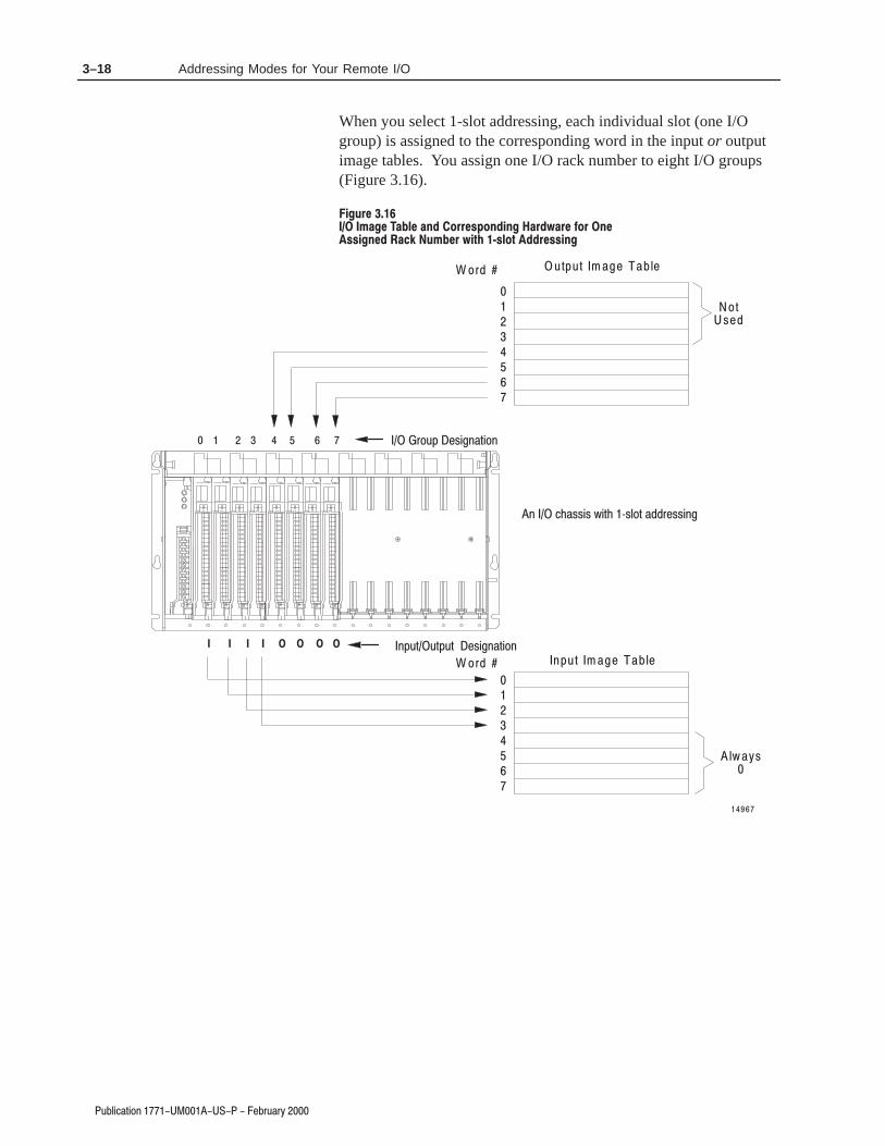
When you select 1-slot addressing, each individual slot (one I/Ogroup) is assigned to the corresponding word in the input or outputimage tables. You assign one I/O rack number to eight I/O groups(Figure 3.16).
"
#
" #! $ !
&*)
#,-)
&(
&(
+*'+* $ #
%'+* $ #
(&+' )" %*"&%
%'+*+*'+* )" %*"&%
% !))") ,"*! .)#&* ())"%

3–19Addressing Modes for Your Remote I/O
)! ( $# &)&*
Definition: The processor addresses one-half of an I/O module slot asone I/O group.
Concept: The physical address of each I/O slot corresponds to twoinput and two output image table words. The type of module youinstall (8-, 16-, or 32-point) determines the number of bits in thesewords that are used.
You select 1/2-slot addressing by setting switches 5 and 6 of the I/Ochassis backplane switch assembly:
• switch 5 to the OFF position
• switch 6 to the ON position
With 1/2-slot addressing, since 32 inputs bits AND 32 output bits areavailable in the processor’s image table for each I/O group, you canmix 8, 16 and 32-point I/O modules in any order in the I/O chassis.
Figure 3.17 illustrates the 1/2-slot addressing concept with a 32-pointI/O module. A 32-point I/O module (with 1/2-slot I/O groups) usestwo words of the image table. When you use 8 and 16-point I/Omodules with 1/2-slot addressing, you get fewer total I/O points.
# % ) ( $ &
) (% ) ( $ &
" ! $ & ' !!$ ( $ & &$ ) %
# % ) ( $ &
) (% ) ( $ &
" ! $ & ' !!$ ( $ & &$ ) %
# ) '
# ) '
% $ # ( # % ) ( $ ) !
' !$ ( &$ ) %
' !$ ( &$ ) %
' !$ ( &$ ) %
' !$ ( &$ ) %
# % ) (# % ) (

3–20 Addressing Modes for Your Remote I/O
The following rules apply when you assign I/O rack numbers for1/2-slot addressing:
• One assigned I/O rack number is made up of eight I/O groups(Figure 3.18).
• The maximum number of I/O racks you can assign to thedifferent chassis sizes are:
one I/O rack to 1771-A1B chassis
two I/O racks to 1771-A2B chassis
three I/O racks to 1771-A3B chassis
four I/O racks to 1771-A4B chassis• You can mix addressing methods in your remote system on a
chassis-by-chassis basis (1-slot and 1/2-slot addressing with32-point I/O modules).
• You cannot assign one I/O rack number to more than one I/Ochassis when you select 1/2-slot addressing.
• Each I/O chassis begins an assigned I/O rack number. Make surethat you set switches 7 and 8 of switch assembly SW1 to the ONposition when you select 1/2-slot addressing. The remote I/Oadapter module automatically assigns the next higher I/O racknumber(s) to the remaining I/O groups of the chassis.

3–21Addressing Modes for Your Remote I/O
! !#
#
! $
!! # $" %!" !!
I I O O
23
01
NotUsed
Always0
01234567
01234567
45
67
Word #
Word #
Output Image Table
Input Image Table
14974
!
! ! !
" $

3–22 Addressing Modes for Your Remote I/O
3"+)#!2).- %"03!05
Some processors support a complementary I/O configuration. Referto the user’s manual for your processor to see if it supports this typeof configuration.
You configure complementary I/O by duplicating an I/O racknumber of one I/O chassis (primary) in another I/O chassis(complementary), I/O group for I/O group. The I/O modules in thecomplementary chassis perform the opposite function of thecorresponding modules in the primary chassis.
! #
Figure 3.19 shows possible module placement for a complementaryI/O configuration with 1/2-slot addressing.
" ! #
.3"+%1+. 2
4 !, / +%
4 !, / +%
0 ), ! 05 1 +. 2 ( ! 1 1 )1
0. 3 / 3, " % 0
., / +% , % - 2! 05 1 +. 2 ( ! 1 1 )1
0 ), ! 05 1 +. 2 ( ! 1 1 )1
0. 3 / 3, " % 0
., / +% , % - 2! 05 1 +. 2 ( ! 1 1 )1
-/32 .$3 +% 32/32 .$3 +% +.#* 20!-1&%0 .$3 +%
32/32 , .$3 +%1 31% 2(% 1!, % .32/32 ), !'% 2!" +% " )21
!- "% )-/32 . 0 .32/32 , .$3 +% .0 /. )- 2 1 )-' +%1+. 2 " +.#* 20!- &%0 , .$3 +%
312 "% %,/25 )& #.00%1/.-$ )-' /0), !05 1+. 2 )1 " +.#* 20!-1&% 0 , .$3 +%
1
" !
#

3–23Addressing Modes for Your Remote I/O
&%"! #&#'
Follow these guidelines when you select 1/2-slot addressing:
• Place input modules opposite output modules; place outputmodules opposite input modules.
• You can use 8, 16 and 32-point I/O modules.
• Output modules placed opposite output modules reflect the samebits in the output image table.
You can use block-transfer modules in a complementary I/Oconfiguration with 1/2-slot addressing. Use block-transfer moduleswith these guidelines:
• When using double-slot block-transfer modules in the primarychassis:– The left-most slot of the two corresponding I/O slots in the
complementary chassis must be empty.– You can place any single-slot I/O module in the right slot
of the two corresponding I/O slots of the complementarychassis
• When using single-slot block-transfer modules, thecorresponding I/O slot in the complementary chassis must beleft empty.
You can have a mix of 1-slot and 2-slot addressing in individualchassis assigned one I/O rack number (with up to eight I/O groups).For example: you can select 2-slot addressing for a 1771-A2B I/Ochassis and 1-slot addressing for a 1771-A1B chassis to make up oneassigned I/O rack number (Figure 3.20).
&#
(! #$$! %"$ ! $$$ $$! !
& #
( $$$&$! ($"% #$$!
( $$$&$! ($"% #$$!
! $$! & #
(! ! )"%
#$$! ! !'&
$$$

3–24 Addressing Modes for Your Remote I/O
!
Not all chassis combinations are acceptable in making I/O racknumber assignments. For example, a 1771-A4B I/O chassis cannotcomplete an assigned I/O rack number that starts in a 1771-A1 I/Ochassis. Refer to Figure 3.B for acceptable beginning I/O groupnumbers when making your I/O rack number assignments.
" "
"
"
"
" "
"
"
"
" "
"
"
"

3–25Addressing Modes for Your Remote I/O
0(& /&+* "-0-3
Table 3.C shows the addressing methods you can achieve with theSeries B chassis and the various remote I/O adapter modules.
! " !
! ! "
! "
!
"
$! $! $!
4 ". + +
+ +
+ + +
4"-&".
". ". +"-&".
". +
+ + +
4"-&". *!
". ". "."-&". *!
". ".
+ ".
+*!&/&+*( )+!0(" ,( ")"*/ 3+0 )0./ 0." * &*,0/ )+!0(" *! * +0/,0/)+!0(" &* /2+ !' "*/ .(+/. +# /%" %..&. "$&**&*$ 2&/% .(+/
"-&". %..&. ("/ 3+0 0." 4.(+/ !!-"..&*$ 2&/% 4,+&*/ )+!0(". +*(3 -"$-!(".. +# /%" /3," +# !,/"- )+!0(" 3+0 0." %&. %-/&. 1(&! #+- ."-&". %..&. +0 *""! ."-&". %..&. /+ %&"1" 4.(+/*! 4.(+/ !!-"..&*$ 2&/% 4,+&*/ *! 4,+&*/ )+!0(".
In this chapter we discussed how to address your hardware and thevarious remote I/O configurations and options you can use in yourremote system.
!
" !
"#

3–26 Addressing Modes for Your Remote I/O

% $"! #%#&
In this chapter, you will learn how to use the indicators on themodule frontplate for troubleshooting the module.
The module has three indicators on the front plate, as shown below.Use these indicators for troubleshooting the module.
#! !$"#
!$"#
!$"#
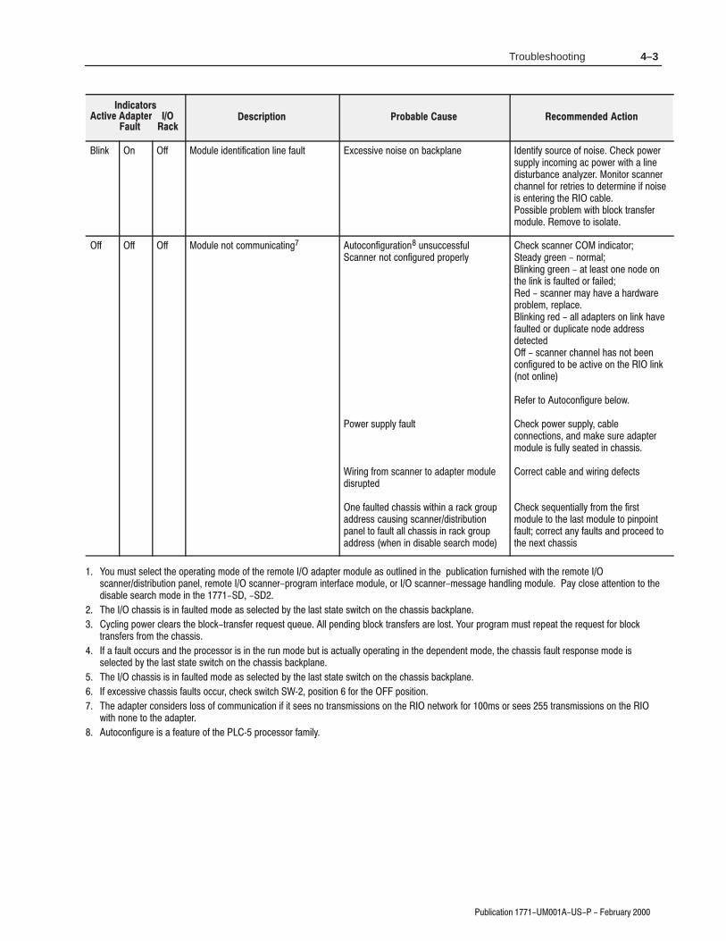
The following table describes problems that may occur, probablecauses, and recommended courses of action.

4–2 Troubleshooting
8&/-'%7-21 ##! )&58%5<
# ! !
"
!
!
1 ** ** 250%/ -1(-'%7-21 5)027) %(%37)5 -6*8//< 23)5%7-21%/ 352')6625 -6 -1 8102()
** 1 ** (%37)5 '5%6, 0)025< *%8/7$%7',(2+ 7-0)287
<'/) 32:)5 )3/%') 02(8/) -*352&/)0 5)2''856
1 /-1. ** 2(8/) 3/%')0)17 )5525 02(8/) -1 -1'255)'7 6/27 /%') 02(8/) -1 '255)'7 6/27 -1 ',%66-6
/-1. -1 81-621 ** 1'255)'7 67%57-1+ +5283 180&)5 5525 -1 67%57-1+ +5283 180&)5 25 5%'. %((5)66
,)'. (-36:-7', 6)77-1+6 )*)5 72 7%&/) 72 9)5-*< %'')37%&/) &)+-11-1+ +5283 180&)5 6)7 6:-7',)6 '255)'7/<
1 1 1 2(8/) 127 '20081-'%7-1+ 1'255)'7 &%8( 5%7) 6)77-1+ ,)'. (-36:-7', 6)77-1+
** 1 1 2(8/) 127 '20081-'%7-1+ !'%1 6:-7', 6)7 *25 %// &87 /%67 6/276 -1 5%'.
)6)7 6'%1 6:-7', 6)77-1+
/-1. ** ** )027) %(%37)5 127 %'7-9)/<'21752//-1+ 6'%11)5 72 %(%37)5'20081-'%7-21 /-1. -6 1250%/ 6'%11)5 0%18%/ 25%872'21*-+85%7-21 :%6 68'')66*8/
52')6625 -6 -1 352+5%0 25 7)67 02()!'%11)5 -6 ,2/(-1+ %(%37)5 02(8/) -1*%8/7 02()21*-+85%7-21 0-60%7',
/%') 352')6625 -1 81 02()%8/7 6,28/( &) '/)%5)( &< 6'%11)5255)'7 7,) '21*-+85%7-21 0-60%7', -)-1'255)'7 5%'. 6-=) 5%'. 180&)5
6 6)48)1') 212***520 723 72 &27720
2(8/) 127 '20081-'%7-1+ 127,)5 5)027) %(%37)5 :-7, 7,)6%0) %((5)66 -6 21 7,) /-1.
255)'7 7,) %((5)66
/-1.%/7)51%7)/<
** (%37)5 02(8/) 127 %'7-9)/<'21752//-1+
(%37)5 02(8/) -1 352')6625 5)67%57/2'.287 02() %(%37)5 72 6'%11)5/-1. -6 1250%/
52')6625 5)67%57 /2'.287 6:-7', 21',%66-6 &%'.3/%1) 6:-7', %66)0&/< 21
)35)66 5)6)7 &87721 72 '/)%5 /2'.287*)%785) 25 '<'/) 32:)5 -* %*7)5 5)3)%7)(%77)0376 -1(-'%7256 %5) 67-// &/-1.-1+',)'.
• 386,&87721 127 :-5)( 3523)5/< 72*-)/( :-5-1+ %50
• :-5-1+ %50 127 '211)'7)( 72%(%37)5 02(8/)
• %(%37)5 02(8/) :%6 5)6)7 &<352')66256'%11)5 7,)1-00)(-%7)/< *%8/7)(
** ** 1 ',%66-6 *%8/7 2 '20081-'%7-2121 /-1.
52&/)0 );-676 &)7:))1
• %(%37)5 %1( 02(8/) -1 ',%66-6 7,)02(8/) :-// 67%< -1 *%8/7 02() 817-/*%8/7 -6 '255)'7)(
• 6,257)( 35-17)( '-5'8-7 &2%5( 5816 21&%'.3/%1) 25 02(8/)
<'/) 32:)5 72 7,) ',%66-6 72 '/)%5 %352&/)0 5)68/7-1+ *520 ,-+, 12-6)
• 5)029) %1( 5)3/%') %// 02(8/)6 21) %7 % 7-0)
• -* 352&/)0 (2)6 127 '/)%5620)7,-1+ -6 :521+ -1 ',%66-6 25 02(8/)
/-1. ** 1 20081-'%7-21 21 /-1. ,%66-69-2/%7-21
266-&/) 6,257)( &%'.3/%1) -1 ',%66-6;')66-9) 12-6) 21 &%'.3/%1)
()17-*< 6285') 2* 12-6) !8335)66287387 02(8/) -1(8'7-9) /2%(6 25 12-6)6285')6 -1 352;-0-7< 72 287387 02(8/):-5-1+ "%5+)7 7,) 352&/)0 &< 63/-77-1+7,) 5%'. -172 60%//)5 5%'.6,)'. ',%66-6 )3/%') ',%66-6 %61)')66%5<
4–3Troubleshooting
6$-+%#5+0/ '$36#3:
-+/, / (( 0&6-' +&'/5+(+%#5+0/ -+/' (#6-5 9%'44+7' /0+4' 0/ $#%,1-#/' &'/5+(: 4063%' 0( /0+4' *'%, 108'34611-: +/%0.+/) #% 108'3 8+5* # -+/'&+4563$#/%' #/#-:;'3 0/+503 4%#//'3%*#//'- (03 3'53+'4 50 &'5'3.+/' +( /0+4'+4 '/5'3+/) 5*' %#$-'044+$-' 130$-'. 8+5* $-0%, 53#/4('3.0&6-' '.07' 50 +40-#5'
(( (( (( 0&6-' /05 %0..6/+%#5+/) 650%0/(+)63#5+0/ 6/46%%'44(6-%#//'3 /05 %0/(+)63'& 1301'3-:
08'3 4611-: (#6-5
!+3+/) (30. 4%#//'3 50 #'3 .0&6-'&+43615'&
/' (#6-5'& %*#44+4 8+5*+/ # 3#%, )3061#&&3'44 %#64+/) 4%#//'3&+453+$65+0/1#/'- 50 (#6-5 #-- %*#44+4 +/ 3#%, )3061#&&3'44 8*'/ +/ &+4#$-' 4'#3%* .0&'
*'%, 4%#//'3 +/&+%#5035'#&: )3''/ /03.#--+/,+/) )3''/ #5 -'#45 0/' /0&' 0/5*' -+/, +4 (#6-5'& 03 (#+-'&'& 4%#//'3 .#: *#7' # *#3&8#3'130$-'. 3'1-#%'-+/,+/) 3'& #-- #'34 0/ -+/, *#7'(#6-5'& 03 &61-+%#5' /0&' #&&3'44&'5'%5'&(( 4%#//'3 %*#//'- *#4 /05 $''/%0/(+)63'& 50 $' #%5+7' 0/ 5*' -+/,/05 0/-+/'
'('3 50 650%0/(+)63' $'-08
*'%, 108'3 4611-: %#$-'%0//'%5+0/4 #/& .#,' 463' #'3.0&6-' +4 (6--: 4'#5'& +/ %*#44+4
033'%5 %#$-' #/& 8+3+/) &'('%54
*'%, 4'26'/5+#--: (30. 5*' (+345.0&6-' 50 5*' -#45 .0&6-' 50 1+/10+/5(#6-5 %033'%5 #/: (#6-54 #/& 130%''& 505*' /'95 %*#44+4
"06 .645 4'-'%5 5*' 01'3#5+/) .0&' 0( 5*' 3'.05' #'3 .0&6-' #4 065-+/'& +/ 5*' 16$-+%#5+0/ (63/+4*'& 8+5* 5*' 3'.05' 4%#//'3&+453+$65+0/ 1#/'- 3'.05' 4%#//'3130)3#. +/5'3(#%' .0&6-' 03 4%#//'3.'44#)' *#/&-+/) .0&6-' #: %-04' #55'/5+0/ 50 5*'&+4#$-' 4'#3%* .0&' +/ 5*'
*' %*#44+4 +4 +/ (#6-5'& .0&' #4 4'-'%5'& $: 5*' -#45 45#5' 48+5%* 0/ 5*' %*#44+4 $#%,1-#/'
:%-+/) 108'3 %-'#34 5*' $-0%,53#/4('3 3'26'45 26'6' -- 1'/&+/) $-0%, 53#/4('34 #3' -045 "063 130)3#. .645 3'1'#5 5*' 3'26'45 (03 $-0%,53#/4('34 (30. 5*' %*#44+4
( # (#6-5 0%%634 #/& 5*' 130%'4403 +4 +/ 5*' 36/ .0&' $65 +4 #%56#--: 01'3#5+/) +/ 5*' &'1'/&'/5 .0&' 5*' %*#44+4 (#6-5 3'410/4' .0&' +44'-'%5'& $: 5*' -#45 45#5' 48+5%* 0/ 5*' %*#44+4 $#%,1-#/'
*' %*#44+4 +4 +/ (#6-5'& .0&' #4 4'-'%5'& $: 5*' -#45 45#5' 48+5%* 0/ 5*' %*#44+4 $#%,1-#/'
( '9%'44+7' %*#44+4 (#6-54 0%%63 %*'%, 48+5%* !< 104+5+0/ (03 5*' 104+5+0/
*' #'3 %0/4+&'34 -044 0( %0..6/+%#5+0/ +( +5 4''4 /0 53#/4.+44+0/4 0/ 5*' /'5803, (03 .4 03 4''4 53#/4.+44+0/4 0/ 5*' 8+5* /0/' 50 5*' #'3
650%0/(+)63' +4 # ('#563' 0( 5*' < 130%'4403 (#.+-:

4–4 Troubleshooting
For a successful autoconfigure, insure that a processor I/O status fileexists, all rack and reset and inhibit bits are zeroed, and the channelis set up for scanner, and the baud rate is correct.
Make sure that:
• the input and output image tables are large enough toaccommodate the rack address you are attempting to assign
• the adapter and chassis switches are set correctly, especiallycommunication rate, rack and group.
• the wiring is correct and properly terminated• the remote I/O racks are not split across scanner channels or
the local chassisIf autoconfigure is still not successful, save the program, clearprocessor memory by disconnecting the battery, create an I/O statusfile, reconfigure the scanner channel, and try again.
1747-SN ScannerFor the adapter to recognized by the 1747-SN scanner module, theG-files must be properly constructed for rack and starting group andscanner switches must be set for the correct communication rate.
1756-DHRIO ScannerFor the adapter to be recognized by the scanner module, the adaptermust be added for each logical rack under the scanner module and beproperly configured in the Logix5550 Controller Organizerconfiguration tree, and the scanner switches must be set correctly forremote I/O and node number.
In this chapter you learned how to use the indicators on the front ofthe module to troubleshoot your module.

$?-64.,>498 F(!(&$ 0-<?,<C
!9/?60 9.,>498 # .3,==4= 601>79=> =69>
3,==4= 4=>,8.0 1> ,?/ 1> ,?/ 1> ,?/
8>0<.9880.> ,-60
$9A0< 4==4:,>498 *,>>=
'30<7,6 4==4:,>498 '(3<
,.5:6,80 ?<<08> )
0C482(::0< .9880.>9< -0>A008 ,8/ 9A0< .9880.>9< -0>A008 ,8/
8@4<98708>,6 98/4>498=#:0<,>498,6 '07:0<,>?<0&>9<,20 '07:0<,>?<0%06,>4@0 ?74/4>C
9 >9 9 9 >9 99 >9 9 9 >9 9 >9 A4>39?> .98/08=,>498
406/ *4<482 <7 ,> "9 *
406/ *4<482 <7 &.<0A '9<;?0 F :9?8/F48.30=
98/?.>9< &4D0%079>0 # -6?0 .,-60
(=0< =?::640/ # <,.5 <0=>,<> =A4>.3,>029<C
* 77 =><,8/0/ .9::0< A4>3 A4<0:0< >0<748,6
* 77 A4>3 77 48=?6,>498 7,B47?7
'0<748,>498 %0=4=>9<Ω F :,<> 8?7-0< F Ω F .,> 89 F+'
208.C 0<>414.,>498A308 :<9/?.> 4= 7,<50/
• & 0<>4140/
• & 6,== 4@4=498 <9?:= .0<>4140/
• ( 64=>0/
• 7,<50/ 19< ,66 ,::64.,-60 /4<0.>4@0=
• '4.5 7,<50/ 19< ,66 ,::64.,-60 ,.>=
9880.> 986C =><,8/0/ A4<0 >9 , >0<748,6 (=0 =><,8/0/ .9::0< A4<0 986C (=0 >34= .98/?.>9< .,>029<C 4819<7,>498 19< :6,88482 .98/?.>9< <9?>482 %010< >9 :?-64.,>498 E8/?=><4,6 ?>97,>498
*4<482 ,8/ <9?8/482 ?4/06480= 19< "94=0 77?84>C

SpecificationsA–2
1 )'!0',+ 5 # .1.4
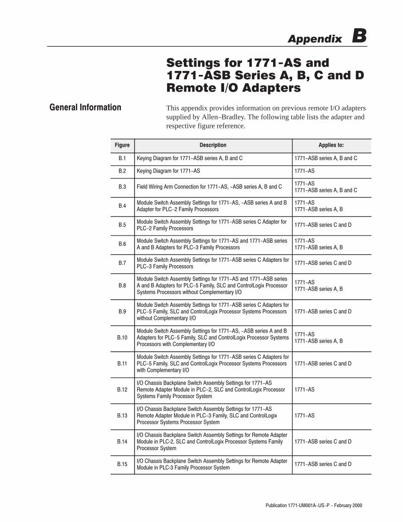
This appendix provides information on previous remote I/O adapterssupplied by Allen–Bradley. The following table lists the adapter andrespective figure reference.
#4'+% '%.* $,. /#.'#/ +" /#.'#/ +"
#4'+% '%.* $,.
'#)" '.'+% .* ,++#!0',+ $,. /#.'#/ +" /#.'#/ +"
,"1)# 2'0!& //#* )4 #00'+%/ $,. /#.'#/ +" "-0#. $,. *')4 .,!#//,./
/#.'#/
,"1)# 2'0!& //#* )4 #00'+%/ $,. /#.'#/ "-0#. $,. *')4 .,!#//,./
/#.'#/ +"
,"1)# 2'0!& //#* )4 #00'+%/ $,. +" /#.'#/ +" "-0#./ $,. *')4 .,!#//,./
/#.'#/
,"1)# 2'0!& //#* )4 #00'+%/ $,. /#.'#/ "-0#./ $,. *')4 .,!#//,./
/#.'#/ +"
,"1)# 2'0!& //#* )4 #00'+%/ $,. +" /#.'#/ +" "-0#./ $,. *')4 +" ,+0.,),%'3 .,!#//,.4/0#*/ .,!#//,./ 2'0&,10 ,*-)#*#+0.4
/#.'#/
,"1)# 2'0!& //#* )4 #00'+%/ $,. /#.'#/ "-0#./ $,. *')4 +" ,+0.,),%'3 .,!#//,. 4/0#*/ .,!#//,./2'0&,10 ,*-)#*#+0.4
/#.'#/ +"
,"1)# 2'0!& //#* )4 #00'+%/ $,. /#.'#/ +" "-0#./ $,. *')4 +" ,+0.,),%'3 .,!#//,. 4/0#*/.,!#//,./ 2'0& ,*-)#*#+0.4
/#.'#/
,"1)# 2'0!& //#* )4 #00'+%/ $,. /#.'#/ "-0#./ $,. *')4 +" ,+0.,),%'3 .,!#//,. 4/0#*/ .,!#//,./2'0& ,*-)#*#+0.4
/#.'#/ +"
&//'/ !(-)+# 2'0!& //#* )4 #00'+%/ $,. #*,0# "-0#. ,"1)# '+ +" ,+0.,),%'3 .,!#//,.4/0#*/ *')4 .,!#//,. 4/0#*
&//'/ !(-)+# 2'0!& //#* )4 #00'+%/ $,. #*,0# "-0#. ,"1)# '+ *')4 +" ,+0.,),%'3.,!#//,. 4/0#*/ .,!#//,. 4/0#*
&//'/ !(-)+# 2'0!& //#* )4 #00'+%/ $,. #*,0# "-0#.,"1)# '+ 5 +" ,+0.,),%'3 .,!#//,. 4/0#*/ *')4.,!#//,. 4/0#*
/#.'#/ +"
&//'/ !(-)+# 2'0!& //#* )4 #00'+%/ $,. #*,0# "-0#.,"1)# '+ 5 *')4 .,!#//,. 4/0#*
/#.'#/ +"

Settings for 1771–AS and 1771–ASB Series A, B, C and D Remote I/O AdaptersB–2
/'%.%*) 3 !,/,2
! " ! "#
$--%- &+')! 0%.$ --!('2 !..%)#- "*, !(*.! +.!,* /'! %) 3 (%'2 ,*!--*, 2-.!(
-!,%!- )
$--%- &+')! 0%.$ --!('2 !..%)#- "*, !(*.! +.!,* /'! %) 3 (%'2 ) *).,*'*#%1 ,*!--*, 2-.!(- %)!(*.! *)"%#/,.%*)
-!,%!- )
$--%- &+')! 0%.$ --!('2 !..%)#- "*, !(*.! +.!,* /'! %) 3 ,*!--*, 2-.!(
-!,%!- )
#
$ ! !
)-!,. &!2%)# ) - !.0!!)/++!, *))!.*, ) '*0!, *))!.*, )
#
$ " "
)-!,. &!2%)# ) - !.0!!)/++!, *))!.*, ) '*0!, *))!.*, )

Settings for 1771–AS and 1771–ASB Series A, B, C and D Remote I/O Adapters B–3
3"+)#!2).- 5 %"03!04
"
!
)-%
()%+$
)-%
. #.--%#2).-
. #.--%#2).-
. #.--%#2).-
. #.--%#2).-
. #.--%#2).-
. #.--%#2).-
. #.--%#2).-
-
%2
%1%2 1%0 13//+)%$ 0!#* 0%12!02/31("322.-
++%-0!$+%4 !"+% #!2 -.
+3%
()%+$
+%!0
!"+%
. -.2 ,!*% #.--%#2).-1 2. 2%0,)-!+1 2(0.3'( (%1% 2%0,)-!+1 !0% #.--%#2%$ )-2%0-!++4 2. 2. !-$ 2. !-$ #!--.2 "% 31%$ &.0 !-4 .2(%0/30/.1%

Settings for 1771–AS and 1771–ASB Series A, B, C and D Remote I/O AdaptersB–4
4#,*$"3*/. 8 "17
$".+
).& /$-# ,, '&0 --$(", !)+ , +$ ,
( *- + !)+ '$&0 +) ,,)+,
*123 (1/40 .4-#&1"#,&
1"$+ .4-#&1"#,&
,5"72
%%1&22 5*3$) 22&-#,7!
5*3$) 22&-#,7!
",5"72 5*3)/43 $/-0,&-&.3"17 ",5"72
5*3) $/-0,&-&.3"17
1*-"17 $)"22*2 /-0,&-&.3"17 $)"22*2
1&22&% *. "3 3/0,/2&%
1&22&% *. "3 #/33/-0&.
",5"72 5*3)/43 $/-0,&-&.3"17
",5"72 5*3) $/-0,&-&.3"17
1*-"17 $)"22*2 /-0,&-&.3"17 $)"22*2
,5"72
"6*-4- "$+ *23".$& $"#,& '3 -"6 #"4% $"#,& '3 -"6 #"4%
&
% & -$)( !)+ '$&0 +) ,,)+,
%
.' +
/$-# & -$)(,
$+,- +).*
.' +
/$-# & -$)(,
. . . . .
. . '' . ''
. '' . '' .
. '' '' '' ''
'' . .
'' . ''
'' '' .

Settings for 1771–AS and 1771–ASB Series A, B, C and D Remote I/O Adapters B–5
3"+)#!2).- 7 %"03!06
)'30%
.$3+% 4)2#( 11%,"+5 %22)-'1 &.0 1%0)%1
!-$ $!/2%01 &.0 6 !,)+5 0.#%11.01
)012 '0.3/ -3,"%0
!"+%
0!#* -3,"%0
!"+%
$$0%11 4)2#( 11%,"+6
4)2#( 11%,"+6
7 !+4!61 7 4)2(.32 #.,/+%,%-2!06 7 !+4!61
7 4)2( #.,/+%,%-2!06 7
7 0),!06 #(!11)1 7 .,/+%,%-2!06 #(!11)1
0%11%$ )- !2 2./+.1%$
0%11%$ )- !2 ".22.,/%-
!5),3, #(!11)1 $)12!-#%
7 !+4!61 7 4)2(.32 #.,/+%,%-2!06
7 !+4!61 7 4)2( #.,/+%,%-2!06 7
7 0),!06 #(!11)1 7 .,/+%,%-2!06 #(!11)1
+4!61
)-* %1/.-1% 7 &.0 1%0)%1 %,3+!2).-
#!- 7 .- &.0 !++ "32 +!12 1+.21.&& &.0 !++ 1+.21
&.0 3-0%120)#2%$
4)2#( .1)2).-
!3$ 7 &2
!3$ 7 &2.2 1%$.2 1%$
7
)-* 0%1/.-1% 14)2#( ,312"% 4(%- 31)-' 2(% &.++.4)-' 1#!--%0,.$3+%1
7
&&
!"+%
!#* 3,"%0 !-$ )012 0.3/ 4)2#( %+%#2).-1 &.0
2(% $$0%11 4)2#( 11%,"+5 6 !,)+5
0.#%11.01
!#*
3,"%0
4)2#( %+%#2).-1
)012 0.3/
3,"%0
4)2#( %+%#2).-1
- - - - -
- - && - &&
- && - && -
- && && && &&
&& - -
&& - &&
&& && -

Settings for 1771–AS and 1771–ASB Series A, B, C and D Remote I/O AdaptersB–6
3"+)#!2).- 7 %"03!06
#!-*
(-% .#," ++&%/ ,,#'!+ (* '
+*#+ ' ),*+ (* &#%/
*(++(*+
)012 '0.3/ -3,"%0!"+%
0!#* -3,"%0!"+%
+4!61
$$0%11 4)2#( 11%,"+6
4)2#( 11%,"+6
0%11%$ )- !2 2./+.1%$
0%11%$ )- !2 ".22.,/%-
!5),3, !#* )12!-#% #!"+% &2 ,!5 "!3$ #!"+% &2 ,!5 "!3$
%
$ %,#(' (* &#%/ *(++(*+
$
-&*.#," ,,#'!
$
-&*.#," ,,#'!
+,
*(-)
-&*
.#,"
%,#('+
- - - - - - - && - - - - - -
- - - - - && - && - - - && - &&
- - - - && - - && - - && - && -
- - - - && && - && - - && && && &&
- - - && - - - && - && - -
- - - && - && - && - && - &&
- - - && && - - && - && && -
- - - && && && - && - && && &&
- - && - - - - && && - - -
- - && - - && - && && - - &&
- - && - && - - && && - && -
- - && - && && - && && - && &&
- - && && - - - && && && - -
- - && && - && - && && && - &&
- - && && && - - && && && && -
- - && && && && - && && && && &&

Settings for 1771–AS and 1771–ASB Series A, B, C and D Remote I/O Adapters B–7
5$-+%#4+0/ :"" '$25#29
)'30%
.$3+% 4)2#( 11%,"+5 %22)-'1 &.0 1%0)%1
!-$ $!/2%01 &.0 6 !,)+5 0.#%11.01
)012 '0.3/ -3,"%0
!#$-' 0!#* -3,"%0
!#$-'
&&2'33 7+4%* 33'.$-9
7+4%* 33'.$-9 2'33'& +/ #4 401-03'&
2'33'& +/ #4 $0440.1'/
7+4%* 03+4+0/
#5& : (4 #5& : (4
04 "3'&
#8+.5. %*#33+3 &+34#/%' )-* %1/.-1% : (02 3'2+'3 '.5-#4+0/
#!- : - (02 #-- $54 -#34 3-043&& (02 #-- 3-043
(02 5/2'342+%4'&
-7#93
:
+/, 2'310/3' 37+4%* .534$' 7*'/ 53+/) 4*' (0--07+/) 3%#//'2 .0&:5-'3
: : : : :
#5& : (4
#5& 7+4* : 2'6+3+0/ #/& : 2'6+3+0/ 3%#//'23 0/-9
((
!"+%
!#* 4)2#( %+%#2).-1 &.0 2(% $$0%11 4)2#(
11%,"+5 6 !,)+5 0.#%11.01
!#*
4)2#( %22)-'
!#*
4)2#( %22)-'
!#*
4)2#( %22)-'
!#*
4)2#( %22)-'
/ / / / / / / (( / / / / (( / / / / / (( (( / / / /
/ / / / / (( / (( / / / (( (( / / / / (( (( (( / / / ((
/ / / / (( / / (( / / (( / (( / / / (( / (( (( / / (( /
/ / / / (( (( / (( / / (( (( (( / / / (( (( (( (( / / (( ((
/ / / (( / / / (( / (( / / ( / / (( / / (( (( / (( / /
/ / / (( / (( / (( / (( / (( (( / / (( / (( (( (( / (( / ((
/ / / (( (( / / (( / (( (( / (( / / (( (( / (( (( / (( (( /
/ / / (( (( (( / (( / (( (( (( (( / / (( (( (( (( (( / (( (( ((
/ / (( / / / / (( (( / / / (( / (( / / / (( (( (( / / /
/ / (( / / (( / (( (( / / (( (( / (( / / (( (( (( (( / / ((
/ / (( / (( / / (( (( / (( / (( / (( / (( / (( (( (( / (( /
/ / (( / (( (( / (( (( / (( (( (( / (( / (( (( (( (( (( / (( ((
/ / (( (( / / / (( (( (( / / (( / (( (( / / (( (( (( (( / /
/ / (( (( / (( / (( (( (( / (( (( / (( (( / (( (( (( (( (( / ((
/ / (( (( (( / / (( (( (( (( / (( / (( (( (( / (( (( (( (( (( /
/ / (( (( (( (( / (( (( (( (( (( (( / (( (( (( (( 04 6#-+&
12 0.3/
3,"%0
4)2#( %+%#2).-1
04' #%, #&&2'33 +3 #/ +--')#- %0/(+)52#4+0/
: 120%'33023 %#/ 3%#/ 2#%,3 :
/ /
/ ((
(( /
(( ((

Settings for 1771–AS and 1771–ASB Series A, B, C and D Remote I/O AdaptersB–8
6%.,&$5,10 :!! (%36$39
$".+
).& /$-# ,, '&0 --$(", !)+ (
, +$ , ( *- +, !)+ '$&0
+) ,,)+, /$-#).- )'*& ' (-+0
,345 *3162 06/%(3 $%.(
3$&- 06/%(3 $%.(
.7$94
''3(44 7,5&+ 44(/%.9#
7,5&+ 44(/%.9#
3(44(' ,0 $5 512.14('
3(44(' ,0 $5 %1551/2(0
$8,/6/ $&- ,45$0&( &$%.( )5 /$8 %$6' &$%.( )5 /$8 %$6'
&
% & -$)( !)+ '$&0 /$-#).-
)'*& ' (-+0
%
.' +
/$-# & -$)(,
$+,- +).*
.' +
/$-# & -$)(,
0 0 0 0 0 )) 0 0
0 0 0 0 )) 0 0 ))
0 0 0 0 )) )) )) 0
0 0 0 )) 0 0 )) ))
0 0 0 )) 0 ))
0 0 0 )) )) 0
0 0 0 )) )) ))
"$.,' )13 231&(44134 10.9

Settings for 1771–AS and 1771–ASB Series A, B, C and D Remote I/O Adapters B–9
0 (&!/&+* 3 # -0-2
)'30%
.$3+% 4)2#( 11%,"+6 %22)-'1 &.0 1%0)%1
!-$ $!/2%01 &.0 7 !,)+6 0.#%11.01 )2(.32
.,/+%,%-2!06
)012 '0.3/ -3,"%0
(#
0!#* -3,"%0
(#
""-#.. 1&/!% ..#) (2
1&/!% ..#) (2
)-* %1/.-1% 3 +* $+- .#-&#. #)0(/&+*+$$ $+- 0*-#./-&!/#"
#!- 3 +* $+- (( 0/ (./ .(+/.+$$ $+- (( .(+/.
(12. 3
1&/!% +.&/&+*
0" 3 $/
0" 3 $/
+/ .#"
!5),3,
#(!11)1 $)12!-#%.## *+/#
0" 3 $/
.2% 3 *" ,-+!#..+-.+,#-/# / 0" +*(2
-#..#" &* / /+,(+.#"
-#..#" &* / +//+),#*
$$
!"+%
!#* %+%#2).- &.0 7 !,)+6 0.#%11.01
4)2(.32 .,/+%,%-2!06
!#*
4)2#( %22)-'
!#*
4)2#( %22)-'
12
0.3/
3,"%0
4)2#(
%+%#2).-1
* * * * * * * $$ * * * * * *
* * * * * $$ * $$ * * * $$ * $$
* * * * $$ * * $$ * * $$ * $$ *
* * * * $$ $$ * $$ * * $$ $$ $$ $$
* * * $$ * * * $$ * $$ * *
* * * $$ * $$ * $$ * $$ * $$
* * * $$ $$ * * $$ * $$ $$ *
* * * $$ $$ $$ * $$ * $$ $$ $$
* * $$ * * * * $$ $$ * * *
* * $$ * * $$ * $$ $$ * * $$
* * $$ * $$ * * $$ $$ * $$ *
* * $$ * $$ $$ * $$ $$ * $$ $$
* * $$ $$ * * * $$ $$ $$ * *
* * $$ $$ * $$ * $$ $$ $$ * $$
* * $$ $$ $$ * * $$ $$ $$ $$ *
* * $$ $$ $$ $$ * $$ $$ $$ $$ $$
3 ,-+!#..+-. !* .!* -!' 3 *" 3 ,-+!#..+-. !* .!* -!'. 33 *" 3 ,-+!#..+-. !* .!* -!'. 33 *" 3 ,-+!#..+-. !* .!* -!'. 33 *" 3 ,-+!#..+-. !* .!* -!'. 33 ,-+!#..+-. !* .!* -!'. 3

Settings for 1771–AS and 1771–ASB Series A, B, C and D Remote I/O AdaptersB–10
6%.,&$5,10 :!! (%36$39
%#/,!
* /'! 0%.$ --!('1 !..%)#- "*, -!,%!-
) +.!,- "*, (%'1 ,*!--*,- 0%.$
*(+'!(!).,1
,345 *3162 06/%(3 $%.(
3$&- 06/%(3 $%.(
.7$94
''3(44 7,5&+ 44(/%.9#
7,5&+ 44(/%.9#
3,/$39 &+$44,4 1/2.(/(05$39 &+$44,4
3(44(' ,0 $5 512.14('
3(44(' ,0 $5 %1551/2(0
3,/$39 &+$44,4 1/2.(/(05$39 &+$44,4
.7$94
$8,/6/ $&- ,45$0&( &$%.( )5 /$8 %$6' &$%.( )5 /$8 %$6'
'!
& !'!.%*) "*, (%'1 0%.$ *(+'!(!).,1
&
/(!,
0%.$ !'!.%*)-
%,-. ,*/+
/(!,
0%.$ !'!.%*)-
0 0 )) 0 0
0 )) 0 0 ))
0 )) )) )) 0
)) 0 0 )) ))
)) 0 ))
)) )) 0
)) )) ))
"$.,' )13 231&(44134 10.9

Settings for 1771–AS and 1771–ASB Series A, B, C and D Remote I/O Adapters B–11
1!)'" 0',+ 4 $!.1 .3
)'30%
.$3+% 4)2#( 11%,"+6 %22)-'1 &.0 1%0)%1
!-$ $!/2%01 &.0 7 !,)+6 0.#%11.01 )2(
.,/+%,%-2!06
)012 '0.3/ -3,"%0
!)$
0!#* -3,"%0
!)$
##.$// 2'0"& //$*!)3
2'0"& //$*!)3 .$//$# '+ 0 0,-
),/$#
.$//$# '+ 0 !,00,*-$+
)2 3/
4 .'* .3 "& //'/ 4 ,*-)$*$+0 .3 "& //'/
4 .'* .3 "& //'/ 4 ,*-)$*$+0 .3 "& //'/
)-* %1/.-1% 4 ,+ %,. /$.'$/ $*1) 0',+
#!- 4 ,+ %,. )) !10 ) /0 /),0/,%% %,. )) /),0/
,%% %,. 1+.$/0.'"0$#
4
2'0"& ,/'0',+
1# 4 %0
1# 4 %0
,0 /$#
!5),3,
#(!11)1 $)12!-#%/$$ +,0$
1# 4 %0
.2% 4 +# -.,"$//,./,-$. 0$ 0 ! 1# ,+)3
%%
!"+%
!#* %+%#2).- &.0 7 !,)+6 0.#%11.01 4)2(
.,/+%,%-2!06
!#*
4)2#(
12 0.3/
3,"%0
4)2#( %+%#2).-1
+ + + + + %% + +
+ + + + %% + + %%
+ + + + %% %% %% +
%% %%
+ + + %% + +
+ + + %% + %%
+ + + %% %% +
+ + + %% %% %%
$$ +,0$ !$),2
.2% 4 " + /" + . "( 4 4 4 4 " + /" + . "(/ 4

Settings for 1771–AS and 1771–ASB Series A, B, C and D Remote I/O AdaptersB–12
,$"+"'& 1 ),)/
" ,)
!**"* #($& -"+! **%$. ++"& * ')
%'+ (+) ',$ "& %"$.
)'**') .*+%
)'**') *+)+ '#',+
!& ()'**') & )*+)+ !**"*!& !**"* %,*+ )*+)+ ++! !**"*
)**"& -"+!
*$'+ )**"& *$+ *$'+ )**"& *$+
*+ ++ -"+!
!& ',+(,+* ' +!"* !**"*)%"& "& $*+ *++!& ',+(,+* ' +!"* !**"* ) &) "0 .!& ,$+ "* ++
$./*
*+ !**"* -"+!
!**"* '* &'+ '&+"& +! !" !*+ &,%1) )',( ') +! **'"+ )# &,%) !**"* '* '&+"& +! !" !*+ &,%) )',( ') +! **'"+ )# &,%)
/', !- '&$/ ()"%)/ !**"* *+ +!"**."+! +' /', !- '+! ()"%)/ & '%($%&+)/!**"* *+ +! ()"%)/ !**"* +' & +!'%($%&+)/ !**"* +'
,+"'& + *."+! +' +! ('*"+"'&+' &) "0 ',+(,+* .") +' +!"* !**"*.!& ,$+ "* ++ *."+! "* *+ +'+! ('*"+"'& ',+(,+* '&&+ +' +!"*!**"* )%"& "& +!") $*+ *++ .!& ,$+',)* & %!"& %'+"'& %/ '&+"&,+) ,$+ ++"'&
" ,)
!**"* #($& -"+! **%$. ++"& * ')
%'+ (+) ',$ "& %"$.
)'**') .*+%
)'**') *+)+ '#',+
!& ()'**') & )*+)+ !**"*!& !**"* %,*+ )*+)+ ++! !**"*
*+ ++ -"+!
!& ',+(,+* ' +!"* !**"*)%"& "& $*+ *++!& ',+(,+* ' +!"* !**"*) &) "0 .!& ,$+ "*++
$./* ,+"'& + *."+! +' +! ('*"+"'&+' &) "0 ',+(,+* .") +' +!"* !**"*.!& ,$+ "* ++ *."+! "* *+ +'+! ('*"+"'& ',+(,+* '&&+ +' +!"*!**"* )%"& "& +!") $*+ *++ .!& ,$+',)* & %!"& %'+"'& %/ '&+"&,+) ,$+ ++"'&
!**"* "& #,( &/ !**"* '&1+"&* *+)+"& )',( ."+! *$'+)**"& & +! "* '&" ,)"& #,( %' $$ '+!) +"%*

Settings for 1771–AS and 1771–ASB Series A, B, C and D Remote I/O Adapters B–13
.&$-$)( 3 +.+1
%#/,!
$--%- &+')! 0%.$ --!('1 !..%)#- "*, "*,
-!,%!- ) !(*.! +.!, * /'! %) 2
(%'1 ,*!--*, 1-.!(
,*!--*, !-.,. *&*/. 2
# ( *+) ,,)+ ( + ,-+- #,,$,# ( #,,$, '.,- + ,-+- - -# #,,$,
,!--%)# 0%.$ 2
3 3,&)- + ,,$(" , & - 3 3,&)- + ,,$(" , & -
-. ..! 0%.$ 2
# ( ).-*.-, )! -#$, #,,$, + '$($( &,- ,-- # ( ).-*.-, )! -#$, #,,$, + ( +"$2 0# ( !.&- $, - -
&01,
-. $--%- 0%.$ 2
3 #,,$, ) , ()- )(-$( -# #$"# ,- (.' + "+).* !)+ -# ,,)$- +% (.' + 3 #,,$, ) , )(-$( -# #$"# ,- (.' + "+).* !)+ -# ,,)$- +% (.' +
! 1). #/ )(&1 *+$'+1 #,,$, , - -#$,,0$-# -) ! 1). #/ )-# *+$'+1 ( )'*& ' (-+1#,,$, , - -# *+$'+1 #,,$, -) ( -# )'*& ' (-+1 #,,$, -)
- ,0$-# -) -# *),$-$)(-) ( +"$2 ).-*.-, 0$+ -) -#$, #,,$, 0# ( !.&- $, - - ! ,0$-# $, , - -) -# *),$-$)( ).-*.-, )(( - -) -#$, #,,$, + '$($( -# $+ &,- ,-- 0# ( !.&- ).+, ( '#$( ')-$)( '1 )(-$(. !- + !.&- - -$)(
&01,
%#/,!
$--%- &+')! 0%.$ --!('1 !..%)#- "*,
-!,%!- ) !(*.! +.!, * /'! %) 2
(%'1 ,*!--*, 1-.!(
,*!--*, !-.,. *&*/. 2
# ( *+) ,,)+ ( + ,-+- #,,$,# ( #,,$, '.,- + ,-+- - -# #,,$,
-. ..! 0%.$ 2
# ( ).-*.-, )! -#$, #,,$, + '$( $( &,- ,-- # ( ).-*.-, )! -#$, #,,$, + ( +"$2 0# ( !.&- $, - -
&01,
3
- ,0$-# -) -# *),$-$)(-) ( +"$2 ).-*.-, 0$+ -) -#$, #,,$, 0# ( !.&- $, - - ! ,0$-# $, , - -) -# *),$-$)( ).-*.-, )(( - -) -#$, #,,$, + '$($( -# $+ &,- ,-- 0# ( !.&- ).+, ( '#$( ')-$)( '1 )(-$(. !- + !.&- - -$)(
). , & - 3,&)- + ,,$(" ). , & - 3,&)- + ,,$(" ). , & - 3,&)- + ,,$(" )- &&)0
+ ,,$(" 0$-# ,
3 #,,$, $( 3 %.* 3 ! (1 3 #,,$, )(-$(,,-+-$(" "+).* 0$-# 3,&)- + ,,$("( -# 3 $, )(!$".+ $( %.* ') 3 && )-# + -$' ,

Settings for 1771–AS and 1771–ASB Series A, B, C and D Remote I/O AdaptersB–14
+#!*!&% 0 (+(.
&$0-"
%..&. ',(*" 1&/ % ..")(3 "//&*$. #+-
."-&". *! ")+/" !,/"- +!0(" &* 4
)&(3 *! +*/-+(+$&2 -+ "..+- 3./")
-+ "..+- "./-/ + '+0/ 4
% '(&))&( % ()*(* ))!) % ))!) $+)* ()*(* * * ))!)
./ //" 1&/ % 4
% &+*'+*) & * !) ))!) ($!% !% #)* )** % &+*'+*) & * !) ))!) ( %(!/- % +#* !) **
#-.)
0
* )-!* *& * '&)!*!&%*& %(!/ &+*'+*) -!( *& * !) ))!) - % +#* !) ** )-!* !) )* *& *
'&)!*!&% &+*'+*) &%%* *& * !) ))!) ($!%!% * !( #)* )** - % +#* &+() % $ !%$&*!&% $. &%*!%+ *( +#* **!&%
&+ )#* 0)#&* ())!% &+ )#* 0)#&* ())!% &+ )#* 0)#&* ())!% &* ##&-
())!% -!* )
./ %..&. 1&/ % 4
0 ))!) &) %&* &%*!% * ! )* %+$0( (&+' &( * ))&!* (" %+$( 0 ))!) &) &%*!% * ! )* %+$( (&+' &( * ))&!* (" %+$(
.&+ , &%#. '(!$(. ))!) )* * !))-!* *& .&+ , &* '(!$(. % &$'#$%*(. ))!) )* * '(!$(. ))!) *& % * &$'#$%*(. ))!) *&
&$0-"
%..&. ',(*" 1&/ % ..")(3 "//&*$. #+-
."-&". *! ")+/" !,/"- +!0(" &* 4
)&(3 *! +*/-+(+$&2 -+ "..+- 3./"). &*
")+/" +*#&$0-/&+*
-+ "..+- "./-/ + '+0/ 4
% '(&))&( % ()*(* ))!) % ))!) $+)* ()*(* * * ))!)
./ //" 1&/ % 4
% &+*'+*) & * !) ))!) ($!% !% #)* )** % &+*'+*) & * !) ))!) ( %(!/- % +#* !) **
#-.)
0
&+ )#* 0)#&* ())!% &+ )#* 0)#&* ())!% &+ )#* 0)#&* ())!% &* ##&-
())!% -!* )
#-.)
)-!* !) )* *& *
'&)!*!&% &+*'+*) &%%* *& * !) ))!)($!% !% * !( #)* )** - % +#* &+()% $ !% $&*!&% $. &%*!%+ *( +#***!&% (&$$% * * .&+ )* )-!* *& * '&)!*!&% *& %(!/ &+*'+*) -!(*& * !) ))!) - % +#* !) **

Settings for 1771–AS and 1771–ASB Series A, B, C and D Remote I/O Adapters B–15
)! ( $# - &)&+
&$0-"
%..&. ',(*" 1&/ % ..")(2 "//&*$. #+-
."-&". *! ")+/" !,/"- +!0(" &*
3 -+ "..+- 2./")
-+ "..+- "./-/ + '+0/ 3
# %&$''$& # &'(&( '' '# '' ' ")'( &'(&( ( ( '' '
./ //" 1&/ % 3
# $)(%)(' $ ( ' '' ' &" # # !'( '((# $)(%)(' $ ( ' '' ' & #& ,*# )!( ' ((
!*+'
-
$) '!( -'!$( &'' # $) '!( -'!$( &'' # $) '!( -'!$( &'' # $( !!$*
&'' # * ('
!*+'
( '* ( ($ ( %$' ( $#($ #& , $)(%)(' * & ($ ( ' '' '*# )!( ' (( '* ( ' '( ($ ( %$' ( $# $)(%)(' $##( ($ ( ' '' '&" # # ( & !'( '(( *# )!( $)&'# " # "$( $# "+ $#( #) (& )!((( $#

Settings for 1771–AS and 1771–ASB Series A, B, C and D Remote I/O AdaptersB–16

2!*(" 1(-, 7 $!/2 /5
Major differences between series are noted in the table below.
2,"1(-, *
' ,&$0,(1( * /$*$ 0$ (/+4 /$ "' ,&$
/#4 /$ ,#
%(/+4 /$ "' ,&$
(/+4 /$ "' ,&$
##$# "$/1(%(" 1(-,
/#4 /$ "' ,&$
##$# (") "$/1(%(" 1(-,
$01/("1(-,0 -/
*(+(1 1(-,0
2..-/10 -,*5 -/
0*-1 ##/$00(,&2..-/10 -/ 0*-1 ##/$00(,&
/#4 /$
-+. 1(!(*(15
-$0 ,-1 02..-/1
!(1 #(&(1 * -$0 02..-/1 !(1 #(&(1 *
-$0 02..-/1 !(1 #(&(1 *
, $+2* 1$ 0$/($0 # .1$/
-++2,(" 1(-,
1$
)!(100
)!(100
)!(100
)!(100
)!(100
$/1(%(" 1(-,0 6 /#-20 * 00 (3 6 /#-20 * 00 (3
").* ,$ 2//$,1 #" #"
' 00(0 (01 ,"$%1 )!(100
%1 )!(100
%1 )!(100
%1 )!(100
%1 )!(100
'$/+ *
(00(. 1(-, '/ '/
-4$/ (00(. 1(-,

Differences Between 1771-ASB Series A, B, C, D and E Remote I/O Adapter ModulesC–2

This appendix presents some of the most commonly asked questionsabout application and operation of the Remote I/O Adapter Module.
The following questions and answers do not cover all possiblequestions, but are representative of the more common ones.
Q. What happens to my inputs and outputs when an adaptercommunication failure occurs?
A. On a communication failure, inputs in this rack will appearin the processor input image table in the last state they werereported to be in before the failure. Outputs in this rack willeither remain in their last state or be turned off, dependingon the I/O chassis backplane switch setting for output laststate.
Q. Is there a way to monitor my remote rack status and takeappropriate action if there is a rack fault or a communicationfailure?
A. Yes. Processor rack fault bits can be monitored.Communication failure can be detected by monitoring theprogram’s block transfer error bit. A diagnostic step arrayand timer can be programmed to monitor the status ofchanging digital inputs. In all cases, the appropriate actioncan be taken, i.e. program a fault routine.
Q. I just replaced my series B adapter with a series E adapter,and now my block transfers are timing out (block transfererror code –9). What’s wrong?
A. Certain scanner modules require series B emulation whichincludes a delay to provide the scanner sufficient time toservice all of its communication ports. If you are using a1772-SD2, 1775-S4, 1775-S4A, 1775-S5, 1775-SR5 or1775-SR scanner, set the link response for unrestricted orseries B emulation (switch S2, position 5 on).
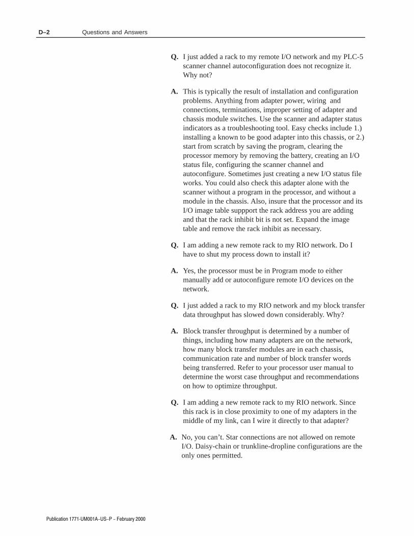
Questions and AnswersD–2
Q. I just added a rack to my remote I/O network and my PLC-5scanner channel autoconfiguration does not recognize it.Why not?
A. This is typically the result of installation and configurationproblems. Anything from adapter power, wiring andconnections, terminations, improper setting of adapter andchassis module switches. Use the scanner and adapter statusindicators as a troubleshooting tool. Easy checks include 1.)installing a known to be good adapter into this chassis, or 2.)start from scratch by saving the program, clearing theprocessor memory by removing the battery, creating an I/Ostatus file, configuring the scanner channel andautoconfigure. Sometimes just creating a new I/O status fileworks. You could also check this adapter alone with thescanner without a program in the processor, and without amodule in the chassis. Also, insure that the processor and itsI/O image table suppport the rack address you are addingand that the rack inhibit bit is not set. Expand the imagetable and remove the rack inhibit as necessary.
Q. I am adding a new remote rack to my RIO network. Do Ihave to shut my process down to install it?
A. Yes, the processor must be in Program mode to eithermanually add or autoconfigure remote I/O devices on thenetwork.
Q. I just added a rack to my RIO network and my block transferdata throughput has slowed down considerably. Why?
A. Block transfer throughput is determined by a number ofthings, including how many adapters are on the network,how many block transfer modules are in each chassis,communication rate and number of block transfer wordsbeing transferred. Refer to your processor user manual todetermine the worst case throughput and recommendationson how to optimize throughput.
Q. I am adding a new remote rack to my RIO network. Sincethis rack is in close proximity to one of my adapters in themiddle of my link, can I wire it directly to that adapter?
A. No, you can’t. Star connections are not allowed on remoteI/O. Daisy-chain or trunkline-dropline configurations are theonly ones permitted.

Questions and Answers D–3
Q. My remote I/O is working fine without termination resistors.Are they really required?
A. Yes, termination resistors are required. Any change in theRIO network installation (i.e. cable length, baud rate) cancause a remote I/O communication failure without propertermination. Installing termination resistors reduces thechance of this occurring.
Q. I have an existing PLC remote I/O system that I’m replacingwith 1771. Are the new adapters compatible with the olderprocessors?
A. Any remote I/O adapter is compatible with any processor.Any and all series/revisions of remote I/O adapter devicescan be mixed on the blue hose. Make sure you set the adapterswitches correctly, since switch positions may have changedon later adapters. Also, older racks and adapters only support2 slot addressing and 8 pt. modules, while newer racks andadapters and racks have no such restrictions.
Q. I’m replacing an existing PLC-2 remote I/O system withnew PLC-5 processors. Will the new processors work withthe older 1771-ASB adapters?
A. Again, any processor will work with any series/revisionremote I/O adapter. Watch your switch settings. Old powersupplies can be used to power your adapters, but cannot beused to power the rack containing a PLC-5 processor. PLC-5processors must be powered by slot power supplies or by a1771-P7 supply.
Q. Specifications for my processor state that it can support 24logical racks, but it won’t accept any rack addresses overrack 17 (16 physical racks).
A. This is a processor limitation. Each RIO channel is limited to16 logical racks which can be scanned by the channel. Theadditional racks can be scanned on another RIO channel, ifpractical.
Q. How do I add a 1771-ASB adapter module to myControlLogix remote I/O network?
A. Simply add the adapter under the 1756-DHRIO scanner inthe Logix5550 Controller Organizer I/O configuration tree.With the scanner, adapter and chassis switches set correctly,download the program to the Logix5550 processor andswitch to Run mode. Communication to the adapter willcommence.

Questions and AnswersD–4
)#"("%$ + !&)&*
Q. How do I add a 1771-ASB adapter module to my SLC1747-SN scanner remote I/O network?
A. Enter the correct rack number, rack size and starting group inthe SLC500 program I/O configuration G-file data screen.With the correct communication rate set on the scanner,download the program to the SLC processor and switch toRun mode. Communication to the adapter will commence.
Q. Ever since I installed fiber optics on my remote I/O network,the adapters won’t communicate.
A. This is probably an installation issue. Check your installationfor the correct application, connection and termination offiber optic cable, and the correct setup of the fiber opticmodule (1771-AF, -AF1). Make sure that no length of bluehose on this network is less than 10ft long, including theblue hose connections from the processor, scanner or adapterto the fiber optic module in the same chassis.
Q. I have a 12-slot chassis but only the modules in the first 8slots are recognized by my program.
A. Check the scan switch (switch S2, position 4) for correctsetting. It probably is set ON “scan all but the last 4 slots.”Set it to OFF.
Q. I just installed a 1771-IL series B analog input module in myremote I/O chassis which already has a 1771-ASB series Aadapter. Now my block transfers to this module are erroring.
A. Adapter modules prior to series C, firmware revision D, arenot compatible with the following modules: !&"!'
!&"!'
!&"!'
!&"!'
!&"!'
!&"!'
!&"!'
!&"!'
!&"!' $
!&"!'
!&"!'
!&"!'
!&"!'
!&"!'
!&"!'
!&"!'

Questions and Answers D–5
#" % # $
!
!
!
!
!
!

Questions and AnswersD–6

3 *'!2'-, > # 0307
)"%# $ "& "$ %$#$ # # $# "%'
"
!#02'$'#1 .0-"3!21 $-0 %#,#0* 31# 1 5#** 1 $-0 31# ', &80"-31 *-!2'-,1$% "$$ # $ ( $ "%$ 1 1&-5, #*-5 ,",-2 7 122#+#,21 ', ,7 31#0 "-!3+#,22'-,
!#02'$'# *#1 .0-"3'21 "32'*'12'-, %;,;0*# 311' '#, /3# !#36 /3'132'*'1#,2 ",1 "#1 #+.*!#+#,21 ",%#0#36 "$$ &%%"
#$ !%* " *$!%$$ % "%$ #2 ,-, .0 "#1 $$'0+2'-,1 ",1 *"-!3+#,22'-, 9 *31%# "#1 32'*'12#301
' $ "$$ "%$
6#+.*# ";2'/3#22# "# !#02'$'!2'-, "3, .0-"3'2 .0 *
- !-+.*7 5'2& !#02'$'!2'-, $-0 31# ', &80"-31 *-!2'-,1 2&# $-**-5',%',$-0+2'-, #!-+#1 .02 -$ 2&# .0-"3!2 *'2#0230# $-0 >!#02'$'#" **#,>0"*#7',"3120'* !-,20-* .0-"3!21
• &'1 #/3'.+#,2 '1 13'2 *# $-0 31# ', *11 '4'1'-, 0-3.1 -0,-,>&80"-31 *-!2'-,1 -,*7
• &# .0-"3!21 &4',% 2&# ..0-.0'2# +0)',%1 2&2 '1 *11 '4'1'-, 0-3.1 0# !#02'$'#" $-0 31# ', -2� #/3'.+#,2 5�# 2&# 13'2 '*'27-$ !-+ ',2'-, 2&2 '1 ..*'!2'-, -0 31# '1 "#2#0+',#" 7 2&# -0 2&# *-!*',1.#!2'-, -$$'!# &4',% (30'1"'!2'-,
-30 12'1$'0# 9 * !#02'$'!2'-, "# * ",1 "#1 #,"0-'21 ",%#0#36 *#1',$-0+2'-,1 13'4,2#1 $-,2 .02'# ',2;%0,2# "# * "-!3+#,22'-, "#1 .0-"3'21',"3120'#*1 "# !-,20<*# **#,>0"*#7 !#02'$';1 .0 *
• #2 ;/3'.#+#,2 !-,4'#,2 9 *32'*'12'-, ",1 "#1 #+.*!#+#,21 "# *11# '4'1'-, 0-3.#1 -3 ,# !-,4'#,2 /39 *32'*'12'-, ",1 "#1#,"0-'21 ,-, ",%#0#36
• #1 .0-"3'21 .-02,2 *# +0/3%# ..0-.0'; "# * !#12 9 "'0# *11# '4'1'-, 0-3.#1 1-,2 !#02'$';1 9 *32'*'12'-, .-30 "320#1;/3'.#+#,21 -= * !-,4#,,!# "# !-+ ','1-, ..*'!2'-, -3 32'*'12'-, #12";2#0+',;# .0 * -3 *# 30#3 *-!* "',1.#!2'-, /3*'$';
"$$ 3# 2- 2&# +-"3*0 ,230# -$ !-,20-* 1712#+ 2&# .0-"3!2 5'2&2&# &'% 2#+.#0230# 02',% "#2#0+',#1 2&# -4#0** 2#+.#0230# !-"# 02',% -$ !-,20-* 1712#+ ', *11 '4'1'-, *-!2'-, &# 2#+.#0230# !-"# 02',% '1+0)#" -, 2&# .0-"3!2 * #* 1 1&-5,
"$$ 0 13'2# "# * ,230# +-"3*'0# "3 1712:+# "# !-,20<*# *#.0-"3'2 7,2 *# 236 *# .*31 ;*#4; "# 2#+.;0230# ";2#0+',# *# 236 "#,1#+ *#"3 !-"# "# 2#+.;0230# "3 1712:+# "# !-,20<*# "3, ",1 3, #+.*!#+#,2"# *11# '4'1'-, # 236 "3 !-"# "# 2#+.;0230# #12 ',"'/3; 130 *;2'/3#22#"3 .0-"3'2
"$%" "$
" $ "$%"
"$ "
$%' %
$ *"$%" #$ !%*
36 "3 !-"# "# 2#+.;0230#
&# $-**-5',% 50,',%1 ..*7 2- .0-"3!21 &4',% !#02'$'!2'-, $-0 31# ',&80"-31 *-!2'-,1
#1 4#02'11#+#,21 13'4,21 1..*'/3#,2 36 .0-"3'21 7,2 * !#02'$'!2'-, .-30 *#30 32'*'12'-, ",1 "#1 #+.*!#+#,21 ",%#0#36
! 6.*-1'-, &80" ?
• 3 12'232'-, -$ !-+.-,#,21 +7 '+.'0 13'2 '*'27 $-0 *11 '4'1'-,
• - ,-2 0#.*!# !-+.-,#,21 3,*#11 .-5#0 &1 ##, 15'2!&#"-$$ -0 2&# 0# '1 ),-5, 2- # ,-,>&80"-31
• - ,-2 "'1!-,,#!2 #/3'.+#,2 3,*#11 .-5#0 &1 ##, 15'2!&#"-$$ -0 2&# 0# '1 ),-5, 2- # ,-,>&80"-31
• - ,-2 "'1!-,,#!2 !-,,#!2-01 3,*#11 .-5#0 &1 ##, 15'2!&#"-$$ -0 2&# 0# '1 ),-5, 2- # ,-,>&80"-31 #!30# ,731#0>13..*'#" !-,,#!2-01 2&2 +2# 2- #62#0,* !'0!3'21 -, ,**#,>0"*#7 .0-"3!2 31',% 1!0#51 1*'"',% *2! 2&0#"#"!-,,#!2-01 -0 -2� +#,1 13!& 2&2 ,7 !-,,#!2'-, !,5'2&12," #52-, * 1#.02',% $-0!# ..*'#" $-0 +','+3+ -$ -,# +',32#
! '1/3# "#6.*-1'-, ?
• 13 12'232'-, "# !-+.-1,21 .#32 0#,"0# !# +2;0'#*',!!#.2 *# .-30 *#1#+.*!#+#,21 "# *11# '4'1'-,
• -3.#0 *# !-30,2 -3 11130#0 /3#*#+.*!#+#,2 #12 ";1'%,;,-, ",%#0#36 4,2 "# 0#+.*!#0 *#1!-+.-1,21
• 4,2 "# "; 0,!� *;/3'.#+#,2 !-3.#0 *# !-30,2 -311130#0 /3# *#+.*!#+#,2 #12 ";1'%,; ,-, ",%#0#36
• 4,2 "# "; 0,!� *#1 !-,,#!2#301 !-3.#0 *# !-30,2 -311130#0 /3# *#+.*!#+#,2 #12 0#!-,,3 ,-, ",%#0#3622!� 2-31 !-,,#!2#301 $-30,'1 .0 *32'*'12#30 #2 0#*';1 36!'0!3'21 #62#0,#1 "3, ..0#'* **#,>0"*#7 9 * '"# "# 4'1*-/3#21 !-3*'11,21 !-,,#!2#301 $'*#2;1 -3 320#1 +-7#,1.#0+#22,2 36 !-,,#6'-,1 "# 0;1'12#0 9 3,# $-0!# "#1;.02'-, "# ,#52-,1 * > )% ..*'/3;# .#,",23 +-',1 3,# +',32#
*-%- '1 0#%'12#0#" 20"#+0) -$ 2&# ,"', 2,"0"1 11-!'2'-,
'1 0#%'12#0#" 20"#+0) -$ **#,>0"*#7 -+.,7 ,!
# 1'%*# #12 * +0/3# ";.-1;# "# *11-!'2'-, "#1 2,"0"1 .-30 *# ,"
#12 3,# +0/3# ";.-1;# "# **#,>0"*#7 -+.,7 ,!

CSA Hazardous Location ApprovalE–2

1(& 0&+* 5 ".1.4
!!."//&*$/(+0
2&0% ,+&*0 )+!1("/ /(+0 /(+0
+),(")"*0.4 1/&*$ ,+&*0 )+!1("/ 2&0% ,+&*0 )+!1("/
$.+1,/ )&3&*$ *! /(+0
!!."//&*$ %.!2."
//&$*&*$ . ' *1)"./ 2&0% /(+0!!."//&*$
10+ +*#&$1." 5 5
',(*" /2&0 % //")(4!"/ .&,0&+* /"00&*$/ #+. ,.+ "//+.
/"00&*$/ #+. &* .")+0"
+*#&$1.0&+* /"00&*$/ #+. ,.+ "//+.
/"00&*$/ #+. ,.+ "//+.
/"00&*$/ 2&0% ,.+ "//+.
%//&/ +)&*0&+*/ ",0("
+)&*0&+*/ %//&/ *! !,0".
+),(")"*0.4 2&0% /(+0!!."//&*$
+),+*"*0/ %.!2."
+*#&$1.0&+* ,(1$ %//&/ ,+2"./1,,(4
+*#&$1.0&+* ,(1$/
+**" 0&+*/ !!&0&+*( !,0"./
!&$*+/0& &*!& 0+./
#"01."/ +# )+!1("
#&"(! 2&.&*$ .) +**" 0&+* ,+&*0/ +**" 0&+*/
$.+1,/&!"*0&*$ &!"*0&*$ 2&0% /(+0 !!."//&*$
. ' *1)". /"(" 0 1/&*$ 0%&/ /2&0 %
. ' *1)". //&$*)"*0 2&0% /(+0!!."//&*$
&*!& 0+./
&*/0((&*$ 0%" )+!1("
'"4&*$
(&*' ."/,+*/" 1*."/0.& 0"! +. /".&"/ ")1(0&+*
)+!1(" ,( ")"*0/(+0 !!."//&*$ /(+0 !!."//&*$
*+&/" &))1*&04 "*(&*$
*+* +),0&(" ,.+!1 0/
,+2". ."-1&.")"*0/
,.&).4 +),(")"*0.4 /2&0 %
-1"/0&+*/ *! */2"./
-1"/0&+*/*/2"./ #."-1"*0(4 /'"!
Index

IndexI–2
,#"+"&% / ),).
*% ## *#&+*#*+ *#&+*
*%%) $&,#* )(,")"% #.
*)"* $,#+"&%
*)"* ")%* '+)*
*'""+"&%*
*-"+! **$#"* *++"%
*-"+! **$#. ,* +& *#+
*-"+! **$#. ,* +& *#+
*-"+! #&+"&%*
*-"+! *++"% * -"+! / / )"* %
'+)
-"+! )"* '+) -"+! % )"* %
-"+! )"* &) '+)
-"+! )"* '+) -"+! &) )"*
-"+! &$'#$%+). -"+! &$'#$%+).
-"+! )"* -"+!&,+
&$'#$%+). -"+!&,+ &$'#$%+).
+)$"%+"% )*"*+&)
+)&,#*!&&+"% ,"
+)&,#*!&&+"% "%"+&)*

$$ &.)$ -
,$"+"'& )'$ % (')+, >4: ,/3* ' 574(1+2 </9. 4:7 *4):2+39'9/43 51+'8+ )4251+9+ '3* 7+9:73 9./8 ,472
:( '2+
'9 4 :( 4 :( '9+ '79 4
! # )'$ %* -( *)" )'$ %* &+ )&$ * &$-
574)+*:7+89+5
+='251+
+=51'3'9/43
/11:897'9/43
-:/*+1/3+
49.+7
*+,/3/9/43
,+'9:7+
/3,4 /3 2'3:'1
'))+88/(/1/9>
/3,4 349 /32'3:'1
9+=9 /11:897'9/43"+).3/)'1 )):7')>
4251+9+3+88
$.'9 /3,472'9/43 /8 2/88/3-
1'7/9>
!+6:+3)+
$.'9 /8 349 /3 9.+ 7/-.9 47*+7
$.'9 /8 :3)1+'7
9.+7 422+398
#8+ (')0 ,47 247+ )422+398
&4:7 '2+ 4)'9/43.43+
+9:73 94 '70+9/3- 422:3/)'9/438 11+3?7'*1+> 4 11+3?7'*1+> 7/;+ '>,/+1* 98 ? .43+ ? % ?
:(1/)'9/43 ??:-:89 ?
%'+ (+ ) * ) &,$
)" * ),)-

NO POSTAGE NECESSARY
IF MAILED IN THE
UNITED STATES
BUSINESS REPLY MAILFIRST-CLASS MAIL PERMIT NO. 18235 CLEVELAND OH
POSTAGE WILL BE PAID BY THE ADDRESSEE
1 ALLEN BRADLEY DRMAYFIELD HEIGHTS OH 44124-9705


=+42,*<276 C%C%#C .+:=*:A
44.6C:*-4.A * "7,3?.44 =<75*<276 =;26.;; 1*; +..6 1.48260 2<; ,=;<75.:; 258:7>.8:7-=,<2>2<A *6- 9=*42<A /7: 57:. <1*6 A.*:; '. -.;206 5*6=/*,<=:. *6- ;=887:< * +:7*-:*60. 7/ *=<75*<276 8:7-=,<; ?7:4-?2-. $1.A 26,4=-. 4702, 8:7,.;;7:; 87?.: *6- 57<276,76<:74 -.>2,.; 78.:*<7: 26<.:/*,.; ;.6;7:; *6- * >*:2.<A 7/ ;7/<?*:. "7,3?.44 2; 76. 7/ <1.?7:4-; 4.*-260 <.,167470A ,758*62.;
'7:4-?2-. :.8:.;.6<*<276
:0.6<26* • =;<:*42* • =;<:2* • *1:*26 • .402=5 • :*B24 • =40*:2* • *6*-* • 124. • 126* " • 7475+2* • 7;<*"2,* • :7*<2* • A8:=; • B.,1".8=+42, • .65*:3 •,=*-7: • 0A8< • 4 #*4>*-7: • 264*6- • :*6,. • .:5*6A • :..,. • =*<.5*4* • 76-=:*; • 760760 • =60*:A • ,.4*6- • 6-2* • 6-76.;2* • :.4*6- • ;:*.4 • <*4A •*5*2,* • *8*6 • 7:-*6 • 7:.* • =?*2< • .+*676 • *4*A;2* • .@2,7 • .<1.:4*6-; • .?).*4*6- • 7:?*A • *32;<*6 • .:= • 12428826.; • 74*6- • 7:<=0*4 • =.:<7"2,7 • !*<*: • "75*62* • "=;;2*# • #*=-2:*+2* • #260*87:. • #47>*32* • #47>.62* • #7=<1/:2,*".8=+42, • #8*26 • #?.-.6 • #?2<B.:4*6- • $*2?*6 • $1*24*6- • $=:3.A •%62<.- :*+ 52:*<.; • %62<.- 260-75 • %62<.- #<*<.; • %:=0=*A • &.6.B=.4* • (=07;4*>2*
44.6C:*-4.A .*-9=*:<.:; #7=<1 #.,76- #<:..< 24?*=3.. ' %# $.4 C *@ C
=+42,*<276 C%C%#C .+:=*:A 78A:201< 44.6C:*-4.A 758*6A 6, :26<.- 26 %#


