1770-6.2.2, Data Highway/ Data Highway Plus/ Data Highway ... · Data Highway II/Data Highway Plus...
128
Data Highway/Data Highway Plus/ Data Highway II/Data HighwayĆ485 Cable Installation Manual
Transcript of 1770-6.2.2, Data Highway/ Data Highway Plus/ Data Highway ... · Data Highway II/Data Highway Plus...

Data Highway/Data Highway Plus/Data Highway II/Data Highway�485Cable
Installation Manual
Because of the variety of uses for this product and because of the differencesbetween solid state products and electromechanical products, those responsiblefor applying and using this product must satisfy themselves as to theacceptability of each application and use of this product. For more information,refer to publication SGI-1.1 (Safety Guidelines For The Application,Installation and Maintenance of Solid State Control).
The illustrations, charts, and layout examples shown in this manual are intendedsolely to illustrate the text of this manual. Because of the many variables andrequirements associated with any particular installation, Allen-BradleyCompany cannot assume responsibility or liability for actual use based upon theillustrative uses and applications.
No patent liability is assumed by Allen-Bradley Company with respect to use ofinformation, circuits, equipment or software described in this text.
Reproduction of the contents of this manual, in whole or in part, without writtenpermission of the Allen-Bradley Company is prohibited.
Throughout this manual we make notes to alert you to possible injury to peopleor damage to equipment under specific circumstances.
ATTENTION: Identifies information about practices orcircumstances that can lead to personal injury or death, propertydamage or economic loss.
Attention helps you:
- Identify a hazard
- Avoid the hazard
- recognize the consequences
Important: Identifies information that is critical for successful application andunderstanding of the product.
Important User Information
Summary of Changes
Data Highway/Data Highway Plus/Data Highway II/Data Highway�485 Cable
Summary of Changes
This release of the publication contains new information for categorizingand routing cables. The new information appears in the following threechapters:
Chapter 2 - Planning a Data Highway and Data Highway Plus CableSystem - I/O Raceway Layout Considerations (pages 2-14 through 2-16)
Chapter 5 - Planning a Data Highway II Cable System - I/O RacewayLayout Considerations (pages 5-10 through 5-13)
Chapter 8 - Planning a Data Highway�485 Cable System - I/O RacewayLayout Considerations (pages 8-4 through 8-6)
We call your attention to all of the new information with revision bars.A revision bar appears as a thick black line in the margin of the page asshown here.
Summary of Changes
Revision Bars
Summary of Changes P�1. . . . . . . . . . . . . . . . . . . . . . . . . . . .
Summary of Changes P�1. . . . . . . . . . . . . . . . . . . . . . . . . . . . . . . . .
Revision Bars P�1. . . . . . . . . . . . . . . . . . . . . . . . . . . . . . . . . . . . . .
Using this Manual i. . . . . . . . . . . . . . . . . . . . . . . . . . . . . . .
Who Should Read this Manual i. . . . . . . . . . . . . . . . . . . . . . . . . .
How this Manual Is Organized i. . . . . . . . . . . . . . . . . . . . . . . . . . .
Frequently Used Terms ii. . . . . . . . . . . . . . . . . . . . . . . . . . . . . . .
Precautionary Notes ii. . . . . . . . . . . . . . . . . . . . . . . . . . . . . . . . . .
Related Products and Publications iii. . . . . . . . . . . . . . . . . . . . . . .
Data Highway and Data Highway Plus Overview 1�1. . . . . . . .
Chapter Overview 1�1. . . . . . . . . . . . . . . . . . . . . . . . . . . . . . . . . . .
The DH and DH+ Cable Systems 1�1. . . . . . . . . . . . . . . . . . . . . . . .
DH Overview 1�1. . . . . . . . . . . . . . . . . . . . . . . . . . . . . . . . . . . . . . .
DH+ Overview 1�4. . . . . . . . . . . . . . . . . . . . . . . . . . . . . . . . . . . . . .
Planning a Data Highway or Data Highway Plus Cable System 2�1. . . . . . . . . . . . . . . . . . . . . . . . . . . . . . .
Chapter Overview 2�1. . . . . . . . . . . . . . . . . . . . . . . . . . . . . . . . . . .
Components of a Network Constructed with Station Connectors and Droplines 2�2. . . . . . . . . . . . . . . . . . . . . . . . . . . . . . . . . . . .
Daisy Chaining (DH+ only) 2�12. . . . . . . . . . . . . . . . . . . . . . . . . . . . .
Necessary Tools 2�12. . . . . . . . . . . . . . . . . . . . . . . . . . . . . . . . . . . .
Determining Cable Length 2�12. . . . . . . . . . . . . . . . . . . . . . . . . . . . .
Selecting the Number of Station Connectors 2�13. . . . . . . . . . . . . . . . .
I/O Raceway Layout Considerations 2�14. . . . . . . . . . . . . . . . . . . . . .
Constructing a Data Highway or Data Highway Plus Cable System 3�1. . . . . . . . . . . . . . . . . . . . . . . . . . . . . . .
Chapter Overview 3�1. . . . . . . . . . . . . . . . . . . . . . . . . . . . . . . . . . .
Construct a Network Using 1770 Station Connectors and Droplines 3�2
Construct a Network Using 1770�XG Connector Kits and Droplines 3�17
Construct a Network Using a Daisy Chain Configuration (DH+ Only) 3�32
Reconfigure a Network Constructed with Droplines and Station Connectors (If Necessary) 3�33. . . . . . . . . . . . . . . . . . . . .
Table of Contents

Table of Contentsii
Data Highway II Overview 4�1. . . . . . . . . . . . . . . . . . . . . . . . .
Chapter Overview 4�1. . . . . . . . . . . . . . . . . . . . . . . . . . . . . . . . . . .
The DH II Cable System 4�1. . . . . . . . . . . . . . . . . . . . . . . . . . . . . . .
How Nodes Communicate on DH II 4�4. . . . . . . . . . . . . . . . . . . . . . .
Communication Between Networks 4�4. . . . . . . . . . . . . . . . . . . . . . .
Communication with Synchronous and Asynchronous Devices 4�4. . .
Planning a Data Highway II Cable System 5�1. . . . . . . . . . . . .
Chapter Overview 5�1. . . . . . . . . . . . . . . . . . . . . . . . . . . . . . . . . . .
Components of a DH II Network 5�1. . . . . . . . . . . . . . . . . . . . . . . . .
Necessary Tools 5�7. . . . . . . . . . . . . . . . . . . . . . . . . . . . . . . . . . . .
Guidelines for Determining Cable Length 5�8. . . . . . . . . . . . . . . . . . .
Selecting the Number of Taps 5�10. . . . . . . . . . . . . . . . . . . . . . . . . . .
I/O Raceway Layout Considerations 5�10. . . . . . . . . . . . . . . . . . . . . .
Constructing a Data Highway II Cable System 6�1. . . . . . . . . .
Chapter Overview 6�1. . . . . . . . . . . . . . . . . . . . . . . . . . . . . . . . . . .
Install the Taps 6�1. . . . . . . . . . . . . . . . . . . . . . . . . . . . . . . . . . . . . .
Prepare the Trunkline Cable for Installation 6�5. . . . . . . . . . . . . . . . .
Attach the Trunkline Cables and Terminators to the Tap 6�7. . . . . . . . .
Install the Droplines 6�9. . . . . . . . . . . . . . . . . . . . . . . . . . . . . . . . . .
Data Highway�485 Overview 7�1. . . . . . . . . . . . . . . . . . . . . . .
Chapter Overview 7�1. . . . . . . . . . . . . . . . . . . . . . . . . . . . . . . . . . .
The DH�485 Cable System 7�1. . . . . . . . . . . . . . . . . . . . . . . . . . . . .
How Nodes Communicate on DH�485 7�2. . . . . . . . . . . . . . . . . . . . .
Planning a Data Highway�485 Cable System 8�1. . . . . . . . . . .
Chapter Overview 8�1. . . . . . . . . . . . . . . . . . . . . . . . . . . . . . . . . . .
Components of a DH�485 Network 8�2. . . . . . . . . . . . . . . . . . . . . . .
Necessary Tools 8�3. . . . . . . . . . . . . . . . . . . . . . . . . . . . . . . . . . . .
Guidelines for Determining Cable Length 8�3. . . . . . . . . . . . . . . . . . .
Selecting the Number of Link Couplers 8�4. . . . . . . . . . . . . . . . . . . . .
I/O Raceway Layout Considerations 8�4. . . . . . . . . . . . . . . . . . . . . .
Constructing a Data Highway�485 Cable System 9�1. . . . . . . .
Chapter Overview 9�1. . . . . . . . . . . . . . . . . . . . . . . . . . . . . . . . . . .
Install the Trunkline and DH-485 Nodes 9�1. . . . . . . . . . . . . . . . . . . .

Table of Contents iii
Constructing RS�232�C and Longline Cables A�1. . . . . . . . . . .
Chapter Overview A�1. . . . . . . . . . . . . . . . . . . . . . . . . . . . . . . . . . .
RS�232�C Connections (Less than 50 Cable Feet) A�1. . . . . . . . . . . .
Longline Connections (up to 7,000 Cable Feet) A�3. . . . . . . . . . . . . . .
Preface
Using this Manual
i
Using this Manual
Read this manual if you are planning and/or installing a Data Highway (DH), Data Highway Plus (DH+), Data Highway II (DH II), or DataHighway-485 (DH-485) cable network. We assume that you have a fundamentalunderstanding of electronics and electrical codes.
This manual explains how to plan and install a DH, DH+, DH II, and DH-485cable system. Since the cable systems for the different networks are not alike,there are separate instructions.
For information on the planning and construction of the different cable systems,refer to the following chapters:
If installing a: See Chapter: Titled:
Data Highway orData Highway PlusCable Network
1 Data Highway and Data Highway Plus Overview
2 Planning a Data Highway or Data Highway Plus Cable System
3 Constructing a Data Highway or Data Highway Plus CableSystem
Data Highway IICable Network
4 Data Highway II Overview
5 Planning a Data Highway II Cable System
6 Constructing a Data Highway II Cable System
Data Highway�485Cable Network
7 Data Highway�485 Overview
8 Planning a Data Highway�485 Cable System
9 Constructing a Data Highway�485 Cable System
Who Should Readthis Manual
How this Manual Is Organized

Using this ManualPreface
ii
We use the following terms and abbreviations in this manual:
When you see this term: It means:
Computer The generic term for any intelligent programmable device thatcan be used with specific interface modules.
DH Data Highway
DH+ Data Highway Plus
DH II Data Highway II
DH�485 Data Highway�485
Dropline Cable that connects a node to a network via a stationconnector.
Node The point at which a device, such as a programmablecontroller, connects to a network.
PLC A Programmable Logic Controller, the term for anyAllen�Bradley PLC product line (such as the PLC�2, PLC�3,PLC�4, PLC�5, SLC�500, etc.).
Trunkline The bus or central part of a cable system.
In this manual, you may see:
ATTENTION: Identifies information about practices orcircumstances that can lead to personal injury or death, propertydamage or economic loss.
Attention helps you:
- Identify a hazard
- Avoid the hazard
- recognize the consequences
Important: Identifies information that is critical for successful application andunderstanding of the product.
Frequently Used Terms
Precautionary Notes

PrefaceUsing this Manual
iii
For more information about related Allen-Bradley products, refer to thefollowing chart.
Product: Catalog Number:
Data Highway/Data Highway Plus Asynchronous InterfaceModule
1770�KF2
Data Highway Communication Controller Interface Module 1771�KE, �KF
Communication Adapter Module 1771�KA2
Data Highway/Data Highway Plus or Remote I/O onBroadband
1771�KRF
PLC�3 Communication Adapter Module 1775�KA
PLC�3 I/O Scanner Communication Adapter Module 1775�SR, �SR5
Data Highway/Data Highway Plus Communication AdapterModule
1785�KA
Data Highway II PLC�2 Communication Interface Module 1779�KP2, �KP2R
Data Highway II PLC�3 Communication Interface Module 1779�KP3, �KP3R
Data Highway II/Data Highway Plus Interface Module 1779�KP5, �KP5R
Data Highway II Synchronous Device Interface Module 1779�KFM, �KFMR
Data Highway II Asynchronous Device Interface Module 1779�KFL, �KFLR
Related Products andPublications

Using this ManualPreface
iv
For more information about related Allen-Bradley publications, refer to thefollowing chart.
Publication: Publication Number:
Data Highway/Data Highway Plus Asynchronous Interface ModuleUser's Manual
1770�6.5.13
Data Highway Communication Controller Interface Module User'sManual
1771�6.5.15
Communication Adapter Module User's Manual 1771�6.5.1
Data Highway on Broadband Interface Module 1771�6.5.59
PLC�3 Communication Adapter Module User's Manual 1775�6.5.1
PLC�3 I/O Scanner Communication Adapter Module User's Manual 1775�6.5.5
Data Highway/Data Highway Plus Communication Adapter ModuleUser's Manual
1785�6.5.1
Data Highway II Overview 1779�2.10
Data Highway II PLC�2 Communication Interface Module User'sManual
1779�6.5.3
Data Highway II PLC�3 Communication Interface Module User'sManual
1779�6.5.5
Data Highway II/Data Highway Plus Interface Module User's Manual 1779�6.5.6
Data Highway II Synchronous Interface Module User's Manual 1779�6.5.2
Data Highway II Asynchronous Interface Module User's Manual 1779�6.5.1
PLC�5 Family Programmable Controllers 1785�6.6.1
Communication Interface Module 1784�2.31
Processor Communication Interface Module 1784�2.21
PC DH�485 Interface Module 1784�2.23

Chapter
1
1-1
Data Highway andData Highway Plus Overview
In this chapter we provide you with an overview of the Data Highway and DataHighway Plus cable systems. We describe:
the DH and DH+ cable systems
how nodes communicate on DH
how nodes communicate on DH+
communication between networks
The Allen-Bradley DH and DH+ systems are Local Area Networks (LANs).They connect programmable controllers, computers, and other devices so theycan communicate and exchange data with one another. A cable system is thephysical means of transmitting this data between nodes. On DH and DH+networks, a node is a hardware interface.
This manual describes the components of a DH and DH+ cable system andexplains how to construct a network. For the most part, the components andconstruction of a DH network are the same as the components and constructionof a DH+ network. There are, however, some differences between the networks.The types of devices used on the networks, and the communication protocol thenetworks use are two of the differences we discuss in this chapter.
This section provides an overview of the Data Highway cable system. In thissection we talk about:
devices used on DH
how nodes communicate on DH
Chapter Overview
The DH and DH+ Cable Systems
DH Overview

DH and DH+ OverviewChapter 1
1-2
Devices Used on DH
Figure 1.1 shows devices that can be used on a DH network.
Important: The following illustration is intended only to depict the variousdevices that can be used on a Data Highway network. You should not interpretthis illustration to be a representation of how to configure your DH network.
Figure 1.1Devices that can be used on a DH network.
PLC-21771-KA2
1770-KF2
Computer
PLC-31775-S5
PLC-31775-KA
Pyramid Integrator5130-RM1
1785-KA
To Data Highway Plus
Data Highway
1771-KE/KF
PersonalComputer
18661
Pyramid Integrator5130-KA
1774 PLC1774-KA
How Nodes Communicate on DH
A DH network uses peer-to-peer communication through a modifiedtoken-passing scheme called floating master. The master controls access tothe network and can initiate messages at any time. With this arrangement, nodesbid for temporary mastership based on their need to send information. In this way, each node has equal access to become the master.
DH and DH+ OverviewChapter 1
1-3
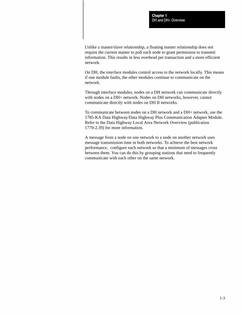
Unlike a master/slave relationship, a floating master relationship does notrequire the current master to poll each node to grant permission to transmitinformation. This results in less overhead per transaction and a more efficientnetwork.
On DH, the interface modules control access to the network locally. This meansif one module faults, the other modules continue to communicate on thenetwork.
Through interface modules, nodes on a DH network can communicate directlywith nodes on a DH+ network. Nodes on DH networks, however, cannotcommunicate directly with nodes on DH II networks.
To communicate between nodes on a DH network and a DH+ network, use the1785-KA Data Highway/Data Highway Plus Communication Adapter Module.Refer to the Data Highway Local Area Network Overview (publication1770-2.39) for more information.
A message from a node on one network to a node on another network usesmessage transmission time in both networks. To achieve the best networkperformance, configure each network so that a minimum of messages crossbetween them. You can do this by grouping stations that need to frequentlycommunicate with each other on the same network.

DH and DH+ OverviewChapter 1
1-4
This section provides an overview of the DH+ cable system. In this section wetalk about:
devices used on DH+
how nodes communicate on DH+
Devices Used on DH+
Figure 1.2 shows the devices that can be used on a DH+ network.
Important: Figure 1.2 is intended only to depict the various devices that can beused on a Data Highway Plus network. You should not interpret this illustrationto be a representation of how to configure your DH+ network.
Figure 1.2Devices that can be used on a DH+ network.
PLC-21785-KA3
1770-KF2
Computer
PLC-31775-S5
Pyramid Integrator5130-RM1
1785-KA
To Data Highway
1785-KE
PersonalComputer
18662
PersonalComputerwith 6001-F1E SWToolkit
T60Workstationwith 6200 SW1784-KT
PLC-5
1784-KT
Pyramid Integrator5130-KA
PersonalComputerwith 6001-F1E2 SWToolkit
1784-KT2
Data Highway Plus
DH+ Overview

DH and DH+ OverviewChapter 1
1-5
How Nodes Communicate on DH+
DH+ uses token-passing protocol to allow nodes on the network to transmitmessages over the cable. With token-passing protocol, only the node possessingthe token can transmit messages. As long as a node possesses the token, it is themaster. This is rotation of link mastership.
When a node has sent all of its messages or used all of its token-hold time, itpasses the token to the node with the next highest address. Token passingcontinues in this manner until the token is passed to the node with the lowestaddress. When the node with the lowest address is finished with the token, thecycle begins again.
On DH+, the interface modules control access to the network locally. Thismeans if one module faults, the other modules continue to communicate on thenetwork.
Through interface modules, nodes on a DH+ network can communicate withnodes on both DH and DH II networks.
To communicate withnodes on DH+ and:
Use this module: Refer to this publication:
DH 1785�KA Data Highway/Data HighwayPlus Communication Adapter Module
Data Highway Local Area Network Overview (pub.no. 1770�2.39)
DH II 1779�KP5 Data Highway II/Data HighwayPlus Interface Module
Data Highway II Local Area Network Overview(pub. no. 1779�2.10)
A message from a node on one network to a node on another network usesmessage transmission time in both networks. To achieve the best networkperformance, configure each network so that a minimum of messages crossbetween them. You can do this by grouping stations that need to frequentlycommunicate with each other on the same network.
In many applications, nodes on a DH+ network need to communicate withdevices such as:
computers
color graphic terminals
dumb terminals
robots
computerized numerical controls (CNC)
motion controllers

DH and DH+ OverviewChapter 1
1-6
To connect these devices to a DH+ interface module, you must provide yourown cable. The interface module and cable you use depends upon the type ofdevice you are connecting.
In this chapter we provided you with a general overview of the DH and DH+cable systems. You are now ready to plan your network. Refer to Chapter 2.
Important: Chapter 2 provides important specifications, guidelines andprecautions that you need to know before you construct your DH or DH+network. Be sure to read Chapter 2 before beginning any construction ofyour cable system.

Chapter
2
2-1
Planning a Data Highway orData Highway Plus Cable System
The Data Highway and Data Highway Plus cable systems give youflexibility to design a communication network that is tailored to yourparticular needs. To take full advantage of this flexibility, you should spendsufficient time planning how to install your cable system beforeassembling any of the hardware.
Important: This chapter provides important specifications, guidelines andprecautions that you need to know before you construct your DH or DH+network. Read this chapter carefully before beginning any construction ofyour cable system.
After you have read this chapter you will be prepared to begin constructingyour DH or DH+ network. This chapter provides information to help youplan a DH or DH+ cable system, including:
components of a network constructed with station connectors anddroplines
daisy chaining (DH+ only)
necessary tools
determining cable length
selecting the type of station connector
selecting the number of station connectors
harmful environmental factors
After reading this chapter, consult schematic and engineering drawings ofyour plant facility for specific information concerning the best location forinstalling your cable network.
Chapter Overview

Planning a Data Highway or Data Highway PlusCable System
Chapter 2
2-2
If you have a DH network, you must construct it using station connectorsand droplines. If you have a DH+ network, you may use station connectorsand droplines, or daisy chaining to connect the devices on your network.
In this section we explain the functions and specifications of thecomponents in a DH or DH+ network when it is constructed with stationconnectors and droplines. The following components are used to constructa DH or DH+ network:
trunkline
droplines
station connectors
terminators
Use Figure 2.1 for reference when reading about these components.
Figure 2.1A DH or DH+ network.
PLC-2Station
PLC-3Station
Mini-PLC-2Station
PLCStation
ComputerStation
DroplineDroplineDropline
Dropline Dropline
StationConnectorand Terminator
StationConnectorand Terminator
Trunkline
Station Connector
19597
Components of a NetworkConstructed with StationConnectors and Droplines

Planning a Data Highway or Data Highway PlusCable System
Chapter 2
2-3
Trunkline
The trunkline is the bus, or the central part of the network cable system.The length of the trunkline depends upon the location of the nodes in yournetwork, however, the maximum length for the trunkline is 10,000 feet(3050 meters).
The trunkline is constructed of Belden 9463 twinaxial cable (Figure 2.2).This cable consists of a twisted pair of conductors wrapped in two layers ofshielding and a drain wire.
Figure 2.2The trunkline and droplines are constructed of Belden 9463Twinaxial Cable.
Insulation
ClearConductor Wire
BlueConductor Wire
Filler Cord
Insulation
DrainWire
Braided ShieldFoil Shield
Outer Jacket
Filler Cord
11606
You can order Belden 9463 twinaxial cable from Allen-Bradley inincrements of 100 feet (30.5 meters). The catalog number is 1770-CD.
For information on installing the trunkline, refer to Chapter 3.
Droplines
Droplines connect nodes to the trunkline. The length of droplines dependsupon your network’s specific needs, however, each dropline must be nomore than 100 feet (30.5 meters) long. If possible, keep the dropline cableslonger than 10 feet (3.0 meters) in length.
Like the trunkline, droplines are constructed of Belden 9463twinaxial cable.
For information on installing the droplines, refer to Chapter 3.

Planning a Data Highway or Data Highway PlusCable System
Chapter 2
2-4
Station Connectors
Station connectors connect droplines to the trunkline and also linktrunkline segments together.
Important: A DH or DH+ network can have no more than 64 nodes. Eachstation connector on the trunkline counts as one of those nodes, even if nodropline or device is connected to that station connector.
There are two types of station connectors that can be used on a DH or DH+network:
1770-SC station connector
1770-XG connector kit
The type of station connector you choose for your network depends uponthe characteristics of your installation.
If your installation: Use the: Because it:
Requires frequent moving andreconfiguration of nodes
1770�XG connector kit Provides plug�in type couplings that are quick andeasy to disconnect and reconnect.
Seldom requires changing anode
1770�SC stationconnector
Provides better physical protection and electricalisolation, and does not require any soldering toinstall.
You may use both types of connectors on the same DH or DH+ network.For example, if you plan to frequently connect and disconnect a personalcomputer to and from the network via an asynchronous module, you canuse a 1770-XG connector kit at that node and 1770-SC connectors at theother nodes.
The following table lists other factors to consider when selecting a stationconnector.
Characteristic: 1770�SC Station Connector: 1770�XG Connector Kit:
Initial Installation Screw Terminal Solder
Disconnection/Reconnection Screw Terminal Plug�in
Grounding Enclosure Tied to EarthGround
None
Enclosure NEMA Type 13 None
Mounting Bolt�down Enclosure None
Testing Required None Electrical Continuity

Planning a Data Highway or Data Highway PlusCable System
Chapter 2
2-5
The following sections describe the two types of station connectors inmore detail.
1770-SC Station ConnectorThe 1770-SC station connector can be used on either a DH or DH+network and can be used instead of the 1770-XG connector kit (describedlater in this chapter).
You need one 1770-SC station connector for each node you want toconnect to the network.
Each station connector connects one dropline to the trunkline and containsthe following components:
a junction box with a removable cover
a terminal block wired with the following:
- 0.05 mfd 500V DC capacitor (terminals 4 and 5)
- jumper (terminals 7 and 9)
- ground wire (terminal 10)
- earth ground wire with lug
a packet containing the following:
- D-shell cable connector hood
- 15-socket female connector
- packet of assembly hardware for the cable connector
- terminator resistor (150 ohm, 1/4 watt)
- shrink tubing
- cable clamp plug
installation instructions
For information on installing a 1770-SC station connector, refer to Chapter 3.

Planning a Data Highway or Data Highway PlusCable System
Chapter 2
2-6
1770-XG Connector KitThe 1770-XG connector kit can be used on a DH or DH+ network, and canbe used instead of a 1770-SC station connector (explained earlier inthis chapter).
You need one 1770-XG connector kit for each node you want to connect tothe network.
Each 1770-XG connector kit connects one dropline to the trunkline andcontains the following components:
a T-connector
a jack connector
two plug connectors
a 15-socket connector
a plug terminator
a jack terminator

Planning a Data Highway or Data Highway PlusCable System
Chapter 2
2-7
Figure 2.3 shows the components included in a 1770-XG connector kit.
Figure 2.3The components of a 1770�XG connector kit.
Plug Terminator
Jack Terminator
T - connector
Jack Connector
Plug Connectors
15 - socket Connector
11607

Planning a Data Highway or Data Highway PlusCable System
Chapter 2
2-8
Table 2.A lists the part numbers and manufacturers for the components inthe 1770-XG connector kit.
Table 2.AManufacturers and part numbers for the 1770�XG connector kit.
Part: Manufacturer: Manufacturer Part Number:
T�connector Trompeter BN 73
Jack connector Trompeter BJ79�9
Plug connector Trompeter PL75�9
15�socket connectorand right�angle hood
ITT Cannon DA�15S (Connector)
DA�51211 (Hood)
Amphenol 1170F�A15S (Connector)
Jack terminator Trompeter
TNGB1�1�150
Plug terminator Trompeter TNG1�1�150
The manufacturers listed in Table 2.A may be contacted at the addresseslisted below:
Trompeter Electronics, Inc.31186 Labaya DriveWestlake Village, CA 91311
ITT Cannon ElectricA Division of International Telephone and Telegraph Corporation666 East Dyer RoadSanta Ana, CA 92702
Amphenol4300 Commerce Ct.Lisle, IL 60532
The 1770-XG connector kit contains a T-connector to link one dropline tothe trunkline and to connect two trunkline segments together. The kit alsocontains a 15-socket connector, which connects the dropline to an interfacemodule on a node. Terminators are also included in the kit.

Planning a Data Highway or Data Highway PlusCable System
Chapter 2
2-9
Figure 2.4 shows how a network can be constructed using the componentsof a 1770-XG connector kit.
Figure 2.4A network constructed using the components of a 1770�XGconnector kit.
NODE
ToT-connector
Dropline
15-pinConnector
T-connector
ToT-connector
Trunkline
Trunkline
18680
PlugConnector
PlugConnector
JackConnector

Planning a Data Highway or Data Highway PlusCable System
Chapter 2
2-10
Figure 2.5 shows a more detailed view of the T-connector, plug connectors,jack connector and the 15-socket connector, and how they connect thenetwork together.
Important: You must assemble the T-connector only as shown.
Figure 2.5Network connections with a 1770�XG connector kit.
JackLeg
JackLeg Plug Connector
Plug Connector
Dropline
Plug Leg
15 - socketConnector
Jack Connector
TrunklineSegment
Trunkline Segment
T - connector
10803B
The T-connector has two jack legs and a plug leg. A plug connector fromthe 1770-XG connector kit attaches to each of the jack legs, and the jackconnector from the kit attaches to the plug leg.
A dropline attaches to one of the plug connectors, and the trunklineattaches to the other plug connector. The trunkline also attaches to thejack connector.
The 15-socket connector attaches to the dropline and then plugs into thenode interface module.
The terminators plug into the T-connector. You need to install twoterminators (one plug terminator and one jack terminator) for a completeDH or DH+ cable system. If you order more than one 1770-XG connectorkit, you will have extra terminators. See the next section for moreinformation about terminators.

Planning a Data Highway or Data Highway PlusCable System
Chapter 2
2-11
Terminators
Figure 2.6 shows the terminators that must be installed in your DH or DH+cable system if you use the 1770-XG connector kit. These terminators areincluded in the 1770-XG connector kit. You must install two terminators(one plug terminator and one jack terminator) for a complete DH orDH+ network.
Figure 2.6Two terminators must be installed for a complete DH or DH+ cablesystem.
Plug Terminator Jack Terminator11608
Figure 2.7 illustrates how the terminators can be positioned in a DH orDH+ network.
Figure 2.7Typical placement of terminators in a DH or DH+ network.
PLC-2Station
PLC-3Station
Mini-PLC-2Station
PLCStation
ComputerStation
Dropline
Dropline
Dropline
Dropline
Dropline
Terminator
Terminator
Trunkline
T-Connectors
11605

Planning a Data Highway or Data Highway PlusCable System
Chapter 2
2-12
You need one 1770-XG connector kit for each node you want to link to theDH network.
The 1770-XG connector kit may be used on a DH or DH+ network.
For information on installing a 1770-XG connector kit, refer to Chapter 3.
If you prefer not to use station connectors and droplines on your DH+network, you may interconnect nodes in a daisy chain fashion. For moreinformation on daisy chaining, refer to Chapter 3.
To install a DH or DH+ cable system, you need the following tools:
rosin core solder
multimeter with needle probes
soldering pencil with fine-point tip (for installing 1770-XG connectors)
wire cutters
wire strippers
heat gun
pair of small needlenose pliers, preferably with smooth jaws
small vice, preferably with smooth jaws
The trunkline on your network is divided into several segments. The cablelength of the trunkline is equal to the total cable length of the trunklinesegments.
Important: When determining the cable length of trunkline segments, besure to measure the actual cable path as it is routed in your network. Makesure to consider vertical dimensions as well as horizontal dimensions. Youshould always calculate the three-dimensional path distance whendetermining cable lengths.
How you configure your DH or DH+ network determines the lengths of alltrunkline segments and droplines.
Daisy Chaining (DH+ only)
Necessary Tools
Determining Cable Length

Planning a Data Highway or Data Highway PlusCable System
Chapter 2
2-13
Important: Remember that the maximum cable length of the trunkline is10,000 feet (3050 meters), and that dropline cables must be no more than100 feet (30.5 meters) in length. If possible, keep the dropline cableslonger than 10 feet (3.0 meters) in length.
Selecting the shortest path for routing the cable will help minimize theamount of cable you will need. The specific details of planning such acable route depends upon the needs of your network.
When determining cable lengths, be sure to follow the guidelines outlinedin the section, ‘‘Harmful Environmental Factors” later in this chapter.
ATTENTION: When determining cable lengths, do not allowtension to be exerted on the cable. Tension on the cable candamage the cable and connectors. To minimize tension, allowsufficient slack in the cable.
Whether you plan to use the 1770-SC station connector or the 1770-XGconnector kit, you must order a connector for each node you want to link tothe network
If you plan to add nodes at a later date, you should order and install thecable and connectors for these additional nodes when you install the initialcable system. This will help avoid the disruption of recabling after thenetwork is in operation.
Important: If you install additional station connectors, do not install thedropline to the connector. An unattached dropline acts as an antenna fornetwork noise.
Important: Remember that a DH or DH+ network can have no more than64 nodes. Each station connector on the trunkline counts as one of thosenodes, even if no dropline or device is connected to that station connector.
Selecting the Number ofStation Connectors

Planning a Data Highway or Data Highway PlusCable System
Chapter 2
2-14
The I/O raceway layout of a system is reflective of where the differenttypes of I/O modules are placed in an I/O chassis. Therefore, you shoulddetermine I/O module placement prior to any layout and routing of wires.However, when planning your I/O module placement, segregate themodules based upon the conductor categories published for each I/Omodule so that you can follow these guidelines. These guidelines coincidewith the guidelines for “the installation of electrical equipment to minimizeelectrical noise inputs to controllers from external sources” in IEEEstandard 518-1982.
Categorize Conductors
Segregate all wires and cables into the three categories shown in Table 2.B. Refer to the publication for each I/O module for the conductorcategory classification of each I/O line.
Table 2.BFollow these guidelines for grouping conductors
Group conductor cables fitting this description: Into thiscategory:
Examples:
Control & ac Power - high�power conductors that are moretolerant of electrical noise than category 2 conductors andmay also cause more noise to be picked up by adjacentconductors.
• corresponds to NEC article�725 class 1
• corresponds to IEEE levels 3 (low susceptibility) & 4 (power)
Category 1 • ac power lines
• high�power digital ac I/O lines - to connect ac I/Omodules rated for high power and high noiseimmunity.
• high�power digital dc I/O lines - to connect dc I/Omodules rated for high power or with input circuitswith long time�constant filters for high noise rejection.They typically connect devices such as hard�contactswitches, relays, and solenoids.
Signal & Communication - low�power conductors that areless tolerant of electrical noise than category 1 conductorsand should also cause less noise to be picked up byadjacent conductors (they connect to sensors andactuators relatively close to the I/O modules).
• corresponds to NEC article�725 classes 2 & 3
• corresponds to IEEE levels 1 (high susceptibility) & 2 (medium susceptibility)
Category 2 • analog I/O lines and dc power lines for analogcircuits
• low�power digital ac/dc I/O lines - to connect to I/Omodules that are rated for low power such aslow�power contact�output modules.
• low�power digital dc I/O lines - to connect dc I/Omodules that are rated for low power and have inputcircuits with short time�constant filters to detect shortpulses. They typically connect to devices such asproximity switches, photo�electric sensors, TTLdevices, and encoders.
• communication cables (remote I/O, extended�localI/O, DH+ , DH�485, RS�232�C, RS�422, RS�423cables) - to connect between processors or to I/Oadapter modules, programming terminals,computers, or data terminals.
I/O Raceway LayoutConsiderations

Planning a Data Highway or Data Highway PlusCable System
Chapter 2
2-15
Group conductor cables fitting this description: Examples:Into thiscategory:
Intra�enclosure - Interconnect the system componentswithin an enclosure
• corresponds to NEC article�725 classes 2 & 3
• corresponds to IEEE levels 1 (high susceptibility) & 2 (medium susceptibility)
Category 3 • low�voltage dc power cables - provide backplanepower to the system components
• communication cables - to connect between systemcomponents within the same enclosure
NOTE: Remote I/O, DH, and DH+ networks must be made of catalog number 1770�CD cable or a cable from the approved vendor list.
DH�485 networks must be made of a cable from the approved vendor list.
Route Conductors
To guard against coupling noise from one conductor to another, follow thegeneral guidelines shown in Table 2.C when routing wires and cables (bothinside and outside of an enclosure). Where it is stated that cables must bein separate raceways, they can be routed in the same ladder or trough ifbarriers are used as required and defined by NEC to provide the separationspecified in Table 2.C. Use the spacing given in these general guidelineswith the following exceptions:
where connection points (for conductors of different categories) on enddevices are closer together than the specified spacing
application-specific configurations for which the spacing is described ina publication for that specific application

Planning a Data Highway or Data Highway PlusCable System
Chapter 2
2-16
Table 2.CFollow these guidelines for routing cables
Route this categoryof conductor cables:
According to these guidelines:
Category 1 These conductors can be routed with machine power conductors of up to 600V ac (feeding up to 100 hpdevices) if this does not violate local codes.
Category 2 General guidelines - these guidelines apply in all cases.
• If it must cross power feed lines, it should do so at right angles.
• Route at least 5 ft from high�voltage enclosures, or sources of rf/microwave radiation.
• If the conductor is in a metal wireway or conduit, each segment of that wireway or conduit must be bondedto each adjacent segment so that is has electrical continuity along its entire length, and must be bonded tothe enclosure at the entry point.
For Unrestricted Applications - these guidelines apply unless you can meet the restricted�applicationguidelines.
• Properly shield (where applicable) and route in a raceway separate from category 1 conductors. They canbe routed in the same ladder or trough with category 1 conductors if barriers are used as required by NECto provide the separation specified in the following items.
• If in a contiguous metallic wireway or conduit, route at least 0.08m (3 in) from category 1 conductors of lessthan 20A; 0.15m (6 in) from ac power lines of 20A or more, but only up to 100 kVA; 0.3m (1 ft) from acpower lines of greater than 100 kVA.
• If not in a contiguous metallic wireway or conduit, route at least 0.15m (6 in) from category 1 conductors ofless than 20A; 0.3m (1 ft) from ac power lines of 20A or more, but only up to 100 kVA; 0.6m (2 ft) from acpower lines of greater than 100 kVA.
For Restricted Applications - remote I/O, DH, DH+, and DH�485 cables can be bundled together withcategory 1 conductors in a molded composite cable if the application can meet these guidelines.
• All category 2 conductors must be bundled together inside a common grounded 95% braided shield (with100% aluminum tape shield) to separate them from the category 1 conductors in the larger bundle.
• Category 1 conductors must carry no more than 15A maximum at 120V maximum to power supply loads,I/O circuit non�inductive loads, or I/O circuit inductive loads that are not switched by hard contacts.
• The total cable length of the remote I/O, DH, DH+, or DH�485 link must be limited to 456 meters (1,500 ft)maximum.
Category 3 Route conductors external to all raceways in the enclosure or in a raceway separate from any category 1conductors with the same spacing listed for category 2 conductors, where possible.
Article 300�3 of the National Electrical Code requires that all conductors (ac and/or dc) in the same raceway must be insulated for the highest voltage applied to any one of theconductors in the raceway.

Chapter
3
3-1
Constructing a Data Highway orData Highway Plus Cable System
Use this chapter to construct a DH and DH+ cable system. It includes how to:
construct a network using 1770-SC station connectors and droplines
construct a network using 1770-XG connector kits and droplines
construct a network using a daisy chain configuration (DH+ only)
reconfigure a network constructed with droplines and station connectors (if necessary)
Important: Before you begin any procedure explained in this chapter, readChapter 2, ‘‘Planning a Data Highway or Data Highway Plus CableSystem” for important specifications, guidelines, and precautions to considerwhen installing your cable network.
To: Refer to Page:
Attach an electrical connector to the dropline 3�2
Test the connector for electrical continuity 3�7
Test the connector for electrical shorts 3�7
Install a 1770�SC station connector 3�9
Install a 1770�XG connector kit 3�18
Construct a network using a daisy chainconfiguration (DH+ only)
3�36
Add a node to DH and DH+ 3�37
Remove a node from DH and DH+ 3�38
Chapter Overview

Chapter 3Constructing a Data Highway or Data Highway Plus Cable System
3-2
Here is a brief outline of the procedures you will follow as you construct yournetwork using 1770-SC station connectors and droplines.
attach an electrical connector to the dropline
test the connector for electrical continuity
test the connector for electrical shorts
install a 1770-SC station connector
network checkout
Attach an Electrical Connector to the Dropline
The first step in constructing a DH or DH+ cable system is to attach anelectrical connector to the dropline. Each dropline in your network must have anelectrical connector to plug the dropline into the node interface module.
The type of electrical connector you attach to the dropline depends upon thedevice you are connecting to the network. Refer to Table 3.A for the mostcommon types of electrical connectors used with the different devices.
Table 3.AProducts that connect to DH or DH+ and the types of connectors they use.
If you have this device: Use this connector:
PLC�5, �10, �12, �15, �25 3�position terminal block or 9�pin connector
5/40 3�position terminal block or 8�pin mini�DIN
5/60 3�position terminal block or 8�pin mini�DIN
1784�KT, �KT2 62�pin connector
1785�KA3 15�socket connector
1775�S5 3�position terminal connector or 9�pin connector
5130�RM1 3�position terminal block
1785�KA 3�position terminal block, 9�pin connector, or15�pin connector
1770�KF2 15�socket connector
1785�KE 3�position terminal block or 9�pin connector
1771�KA2 15�socket connector
1775�KA 15�socket connector
1771�KE/KF 15�socket connector
5130�KA 3�position terminal block
Construct a Network Using1770 Station Connectors and Droplines

Constructing a Data Highway orData Highway Plus Cable System
Chapter 3
3-3
Refer to the following procedure for instructions on how to attach the variouselectrical connectors to a dropline.
To attach an electrical connector to a dropline, follow these steps:
1. Cut the Belden 9463 twinaxial cable to the length desired for a dropline.
Important: Remember, a dropline must be no more than 100 feet (30.5 meters)in length. If possible, keep the dropline cables longer than 10 feet (3.0 meters)in length. Refer to ‘‘Determining Cable Length” in Chapter 2 for guidelines ondetermining appropriate cable lengths.
2. Slip the large-diameter piece of shrink tubing over one end of the dropline.
3. Using wire strippers, remove 1 inch (25.4 mm) of the outer jacket from thesame end of the dropline.
Important: In the next step, do not cut the drain wire.
4. Using wire cutters, remove the exposed portions of the foil shield, braidedshield, and filler cords from the cable.
5. Remove 0.125 inch (3.2 mm) of insulation from the end of eachconductor wire.
Insulation
ClearConductor Wire
BlueConductor Wire
Filler Cord
Insulation
DrainWire
Braided ShieldFoil Shield
Outer Jacket
Filler Cord
11606
6. Tin the blue conductor wire, the clear conductor wire and the drain wirewith solder.

Chapter 3Constructing a Data Highway or Data Highway Plus Cable System
3-4
If you have a 15-socket connector, continue with step 7. If you do not have a15-socket connector, continue with step 9.
7. Remove the screws that attach the right-angle hood to the 15-socketconnector and separate the hood from the connector.
Large-diameterShrink Tubing(clear plastic)
Small-diameterShrink Tubing(clear plastic)
SmallScrews
Locking Clip
Locking Clip
Cable Clamp
Large Screw
PinHoles
Right-angle Hood
10806
8. Guide the dropline through the circular hole in the right-angle hood.
9. Keeping the pins on the electrical connector facing up, clamp theconnector securely in a vise. Do not over-tighten the vise.
10. Cut the small-diameter shrink tubing into three equal pieces, and slip onepiece over the drain wire, one piece over the blue conductor wire, and onepiece over the clear conductor wire.
If you have this connector: Go to step:
3�position terminal block 11
9�pin 12
15�socket 13
62�pin 14

Constructing a Data Highway orData Highway Plus Cable System
Chapter 3
3-5
11. Connect the dropline to the 3-position terminal block connector.
Secure this wire: To this terminal:
Clear conductor wire 1
Drain wire SH
Blue conductor wire 2
Clear
Shield
Blue
Clear
Shield
Blue
1
SH
2
1
SH
2
Terminals on3 - pin terminal block
Twinaxial cable
19603
Go to step 15.
12. Connect the dropline to the 9-pin electrical connector.
Connect this wire: To this pin number:
Blue conductor wire 5
Drain wire 7
Clear conductor wire 1
Blue
Drain
Clear
Twinaxial Cable
5
7
1
18767
Go to step 15.

Chapter 3Constructing a Data Highway or Data Highway Plus Cable System
3-6
13. Attach the dropline to the 15-socket connector and secure each wire with abead of solder.
Important: In this step, take care so that you do not heat the shrink tubingwhen soldering.
Connect this wire: To this pin number:
Blue conductor wire 6
Clear conductor wire 8
Drain wire 7
12
91
4
6
7
8
Pins
15 - socket Connector
ClearConductorWire
Small - diameterShrink Tubing
Drain Wire
BlueConductorWire
Large - diameterShrink Tubing
Dropline
Right - angleHood
10805
15
Go to step 15.

Constructing a Data Highway orData Highway Plus Cable System
Chapter 3
3-7
14. Attach the dropline to the 62-pin connector.
Connect this wire: To this pin number:
Blue conductor wire 34
Clear conductor wire 36
Drain wire 35
15. Slide all three pieces of the small-diameter shrink tubing over the solderpoints at the connector. Using a heat gun, heat the tubing until the piecesfit snugly on the conductor wires and the drain wire.
16. Slide the large-diameter shrink tubing as close as possible to the electricalconnector. Using a heat gun, heat the tubing until it fits snugly around theend of the dropline.
If you: Then:
Have a 15�socket connector Continues with step 17.
Do not have a 15�socket connector Check for electrical continuity and shorts betweenconductors. Refer to the next procedure.
17. Position the right-angle hood to the 15-socket connector and install thescrews through the locking clips. Tighten the screws to secure the hood tothe connector.
18. Insert the cable clamp through the slot in the right-angle hood. Insert thecurved edge of the clamp into the slot first. Install the large screw into theslot and tighten it so that the clamp holds the dropline cable securely.
After the you have soldered the electrical connector to the dropline andassembled the connector, you need to check for electrical continuity and shortsbetween conductors.
Test the Connector for Electrical Continuity
To check for electrical continuity, leave the connector secured in the vise andcheck for continuity between the station connector and the electrical connectoror the plug connector and the electrical connector.

Chapter 3Constructing a Data Highway or Data Highway Plus Cable System
3-8
Test the Connector for Electrical Shorts
After you have soldered the connector to the dropline, you must check forelectrical shorts. To do this, measure the resistance between:
the blue conductor wire and the drain wire
the drain wire and the clear conductor wire
the clear conductor wire and the blue conductor wire
If the resistance readings you obtain indicate there are no shorts, you are nowready to attach the dropline to a station connector. Refer to the section later inthis chapter.
If the resistance readings you obtain indicate an electrical short exists, check theother end of the dropline for a station connector.
If the dropline: Then go to this procedure:
Does not have a station connector ``Electrical Short Exists and DroplineDoes Not Have Station Connector"
Has a station connector ``Electrical Short Exists and DroplineHas Station Connector"
Electrical Short Exists and Dropline Does Not Have Station ConnectorCheck for frayed wire or wire fragments at the electrical connector, or at theother end of the cable. Check the resistance readings again.
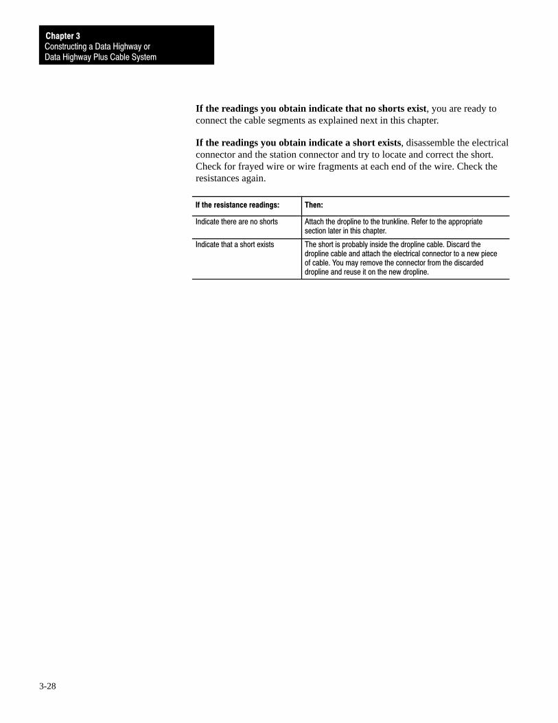
If the resistance readings: Then:
Indicate there are no shorts Attach a station connector to the dropline. Refer to ``Selecting theType of Station Connector" in Chapter 2 for guidelines on choosingthe station connector appropriate for your application.
Indicate that a short exists Disassemble the electrical connector, try to locate and repair theshort, and test the resistances again.
After finding and repairing the short, test the resistances again:
If the resistance readings: Then:
Indicate there are no shorts Attach a station connector to the dropline. Refer to ``Selecting theType of Station Connector" in Chapter 2 for guidelines on choosingthe station connector appropriate for your application.
Indicate that a short exists The short is probably inside the dropline cable. Discard thedropline cable and attach the electrical connector to a new pieceof cable. You may remove the connector from the discardeddropline and reuse it on the new dropline.

Constructing a Data Highway orData Highway Plus Cable System
Chapter 3
3-9
Electrical Short Exists and Dropline Has Station ConnectorDisassemble the electrical connector and the station connector and try to locateand correct the short. Check the resistances.
If the resistance readings: Then:
Indicate there are no shorts Attach the dropline to the trunkline. Refer to the appropriatesection later in this chapter.
Indicate that a short exists The short is probably inside the dropline cable. Discard thedropline cable and attach the electrical connector to a new pieceof cable. You may remove the connector from the discardeddropline and reuse it on the new dropline.
Install the 1770�SC Station Connector
Use this section to construct a trunkline using a 1770-SC station connector.These procedures apply to both DH and DH+ networks. Here is a brief outlineof the procedures you will follow when constructing a trunkline using the1770-SC station connector.
connect the dropline to the station connector
connect the trunkline segments to the station connector
terminate the trunkline
mount the station connector
Important: If necessary, install the electrical connector to the dropline asexplained in the section, ‘‘Attach an Electrical Connector to the Dropline”earlier in this chapter.
A 1770-SC station connector links a dropline cable to the trunkline and alsolinks two trunkline segments together.

Chapter 3Constructing a Data Highway or Data Highway Plus Cable System
3-10
Figure 3.1A cable network constructed with 1770�SC station connectors.
StationConnector
Node
Dropline
StationConnector
Dropline
Node
StationConnector
Dropline
Node
StationConnector
Dropline
Node
StationConnector
Node
Trunkline Cable Distance, 10,000 ft. Max.
Dropline
11275
The first step in constructing a network with 1770-SC station connectors is toconnect the dropline to a station connector. Refer to the next section forinstructions.

Constructing a Data Highway orData Highway Plus Cable System
Chapter 3
3-11
Connect the Dropline to the Station Connector
Important: Remove the terminal block from inside the station connector beforeattaching the dropline and trunkline segments to the station connector. Thismakes it easier to connect the wires to the screw-clamp terminals.
Important: Remember that dropline cables must be no more than 100 feet (30.5 meters) in length. If possible, keep the dropline cables longer than 10 feet(3.0 meters) in length.
To connect the dropline to the station connector, follow these steps.
Use Figure 3.2 for reference when performing steps 1 and 2.
Figure 3.2Prepare the dropline to be attached to the station connector.
Insulation
ClearConductor Wire
BlueConductor Wire
Filler Cord
Insulation
DrainWire
Braided ShieldFoil Shield
Outer Jacket
Filler Cord
11606
Important: In the next step, do not cut the drain wire or the conductor wires.
1. Working from the end of the dropline cable that does not have theelectrical connector attached to it, remove 3 inches (7.6 cm) of the outerjacket, foil shield, braided shield and filler cords.
2. Using wire strippers, remove 0.5 inch (12.7 mm) of insulation from theend of each conductor wire.
Chapter 3Constructing a Data Highway or Data Highway Plus Cable System
3-12
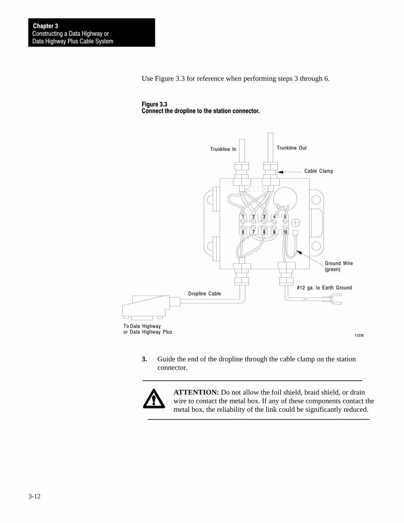
Use Figure 3.3 for reference when performing steps 3 through 6.
Figure 3.3Connect the dropline to the station connector.
Trunkline OutTrunkline In
Cable Clamp
Ground Wire(green)
#12 ga. to Earth GroundDropline Cable
Toor Data Highway Plus
11276
Data Highway
3. Guide the end of the dropline through the cable clamp on the stationconnector.
ATTENTION: Do not allow the foil shield, braid shield, or drainwire to contact the metal box. If any of these components contact themetal box, the reliability of the link could be significantly reduced.

Constructing a Data Highway orData Highway Plus Cable System
Chapter 3
3-13
4. Using wire cutters, trim the drain wire to the following specifications.
If the dropline cable is: Then:
10�100 feet ( 3.0�30.5 meters) inlength
Trim the dropline cable drain wire to 1.5inches (3.8 cm) and secure it to terminal 7.
Less than 10 feet (3.0 meters) inlength
Trim the dropline cable drain wire so it iseven with the outer jacket.
5. Make the following connections:
Secure this wire: To this terminal number:
Blue conductor wire 6
Clear conductor wire 8
6. Secure the dropline cable by tightening the cable clamp around it.
After the dropline is attached to the station connector, you must attach thetrunkline segments to the station connector. Refer to the next section forinstructions.
Connect the Trunkline Segments to the Station ConnectorAfter attaching the dropline to the station connector, connect a trunklinesegment to a station connector by following these steps.
Important: In the next step, do not cut the drain wire or conductor wires.
1. Remove 3 inches (7.6 cm) of the outer jacket, foil shield, braided shieldand filler cords from the mating ends of two trunkline segments.
2. Using wire cutters, trim the drain wire to a length of 2 inches (5.0 cm).
3. Using wire strippers, remove 0.5 inch (12.7 mm) of insulation from theend of each conductor wire.
4. Guide the end of each trunkline segment through one of the cable clampsat the top of the station connector.
ATTENTION: Do not allow the foil shield, braid shield, or drainwire to contact the metal box. If any of these components contact themetal box, the reliability of the link could be significantly reduced.
5. Make the following connections on the terminal block:

Chapter 3Constructing a Data Highway or Data Highway Plus Cable System
3-14
Attach these wires: To this terminal number:
Two blue conductor wires (onefrom each trunkline segment)
1
Two drain wires (one from eachtrunkline segment)
2
Two clear conductor wires (onefrom each trunkline segment)
3
6. Secure the trunkline segments by tightening the cable clamps around them.
After all of the droplines and trunkline segments have been connected together,you must install a 150-ohm terminating resistor at each end of the trunkline.Refer to the next section for instructions.
Terminate the TrunklineTo minimize signal reflections from the ends of the trunkline, you must attach a150-ohm 1/2 watt terminating resistor on the first and last station connectors onthe trunkline. (The terms ‘‘first” and ‘‘last” refer to the physical location of thenode along the trunkline, and not the node’s station number.)
To install the terminating resistors, refer to Figure 3.3 and follow these steps.
1. Connect the dropline to the station connector. Refer to the procedureexplained earlier in this chapter for instructions.
2. Connect the one trunkline segment to the station connector. Refer to theprocedure explained earlier in this chapter for instructions.
3. Slip a one-inch (2.5 cm) length of shrink tubing over the 150-ohmterminating resistor and connect the leads of the resistor to screw-clampterminals 1 and 3.
4. Insert the cable clamp plug into the unused cable clamp on the stationconnector. Tighten the cable clamp to hold the plug securely in place.
Repeat steps 1 through 4 at the other end of the trunkline.
After all the necessary connections are made to the station connector, you mustmount the station connector to a secure foundation. Refer to the next section forinstructions.

Constructing a Data Highway orData Highway Plus Cable System
Chapter 3
3-15
Mount the Station ConnectorNow that all the necessary connections are made to the station connector, mountthe station connector by following these steps.
1. Select a secure foundation for mounting the station connector. If necessary,drill and/or tap mounting holes according to the dimensions shown inFigure 3.4.
Figure 3.4If necessary, drill and/or tap mounting holes for the station connector.
10.8cm(4.25")
13.5cm(W = 5.3")
8.1cm(D = 3.2")m
5.1cm(2.0")
10.2cm(4.0")
14.0cm(L = 5.5")
12.1cm(4.75")
Terminal Block
Top View, Less Cover Side View11274
2. If you removed the terminal block from the station connector, mount theblock inside the enclosure.
3. Attach the ground wire from the station connector to earth ground. The lugon the end of the ground wire accepts a number 10 screw.
Important: In the next step, do not pinch any wires between the cover plate andthe station connector enclosure. Also do not damage the gasket on the coverplate, since this can nullify the NEMA type 13 rating of the station connector.
4. Attach the cover plate to the station connector.

Chapter 3Constructing a Data Highway or Data Highway Plus Cable System
3-16
Network Checkout
After you have installed your network using 1770-SC station connectors,complete the following steps before you attach any modules to the droplinesto check the system integrity.
Important: If the trunkline is routed between several building structures,building-to-building ground potential may differ. This checkout should be doneon a per building basis.
1. Check the resistance between the following points.
sockets 6 and 8 on each 15-socket connector
the blue and clear wires on each station connector
The readings should be 75 ohms plus the resistance of the Belden 9463cable. Belden 9463 has a typical resistance of one ohm per 100 feet.
The resistance readings should be no less than 75 ohms +/- 1%, and nomore than 125 ohms +/- 10%. If the resistances do not fall within thisparameter, you must locate and correct the error before network start-up.
2. Remove the resistors from the end station connectors and check theresistance between sockets 6 and 8 on any 15-socket connector on thenetwork. There should be infinite resistance.
3. Connect socket 8 to building steel (chassis ground). The resistance onsocket 8 should be 1,000 ohms or less, and the resistance on sockets 6 and7 should be one meg ohms or more.
If these readings are not found, you must locate and correct the problembefore network start-up.
If the resistances are within the guidelines outlined above, you can start up thenetwork.

Constructing a Data Highway orData Highway Plus Cable System
Chapter 3
3-17
Here is a brief outline of the procedures you will follow as you construct yournetwork using 1770-XG connector kits and droplines.
attach an electrical connector to the dropline
test the connector for electrical continuity
test the connector for electrical shorts
install a 1770-XG connector kit
Attach an Electrical Connector to the Dropline
Refer to the procedure explained in the section ‘‘Construct a Network Using1770-SC Station Connectors and Droplines” earlier in this chapter.
Test the Connector for Electrical Continuity
Refer to the procedure explained in the section ‘‘Construct a Network Using1770-SC Station Connectors and Droplines” earlier in this chapter.
Test the Connector for Electrical Shorts
Refer to the procedure explained in the section ‘‘Construct a Network Using1770-SC Station Connectors and Droplines” earlier in this chapter.
Install a 1770�XG Connector Kit
Here is a brief outline of the steps you will follow as you install a 1770-XGconnector kit:
solder the jack or plug connector to a cable segment
test the connector for electrical continuity
connect the cable segments
terminate the trunkline
Solder the Jack or Plug Connector to a Cable SegmentThe 1770-XG connector kit comes with a jack connector and two plugconnectors. Although the internal components of a jack connector and a plugconnector differ in appearance, the internal components perform the samefunctions and have the same names (Figure 3.5).
Construct a Network Using1770�XG Connector Kits andDroplines

Chapter 3Constructing a Data Highway or Data Highway Plus Cable System
3-18
Figure 3.5The internal components of a jack connector and a plug connector.
TwinaxialCable
Wrench CrimpNut
Cone
Cone Dielectric
Insulating Washer
Notched Insert
Pin
Pin Dielectric
Shield
Shield Dielectric
PlugConnector Body
JackConnector Body
10804
Since the components are so similar, the procedure for soldering a jackconnector or a plug connector to a cable segment is the same for eitherconnector. You can also follow the same procedure whether you are solderingthe connector to a dropline or to a trunkline cable segment.

Constructing a Data Highway orData Highway Plus Cable System
Chapter 3
3-19
Important: When using a 1770-XG connector kit, droplines will have anelectrical connector attached to one end of the dropline and a plug connectorsoldered to the other end. Trunkline segments will have a plug connectorsoldered to one end of the cable segment and a jack connector soldered to theother end.
Here is a brief outline of the steps you will follow as you solder a jack or plugconnector to a cable segment:
install the cone assembly
prepare the cable for soldering
solder the conductor wires
install the jack or plug connector
1. Install the cone assembly.
a. Slide the wrench crimp nut onto the cable so that the threaded end ofthe nut is toward the cable end that you are going to solder to theconnector.
WrenchCrimpNut
TrunklineSegment
18733
Important: In the next step, be sure you do not damage the foil shield or thebraided shield.
b. Using wire strippers, remove approximately 1 inch (2.5 cm) of theouter jacket from the end of the cable.
25.4mm(1.0")
BraidedShield
FoilShield
18734
OuterJacket

Chapter 3Constructing a Data Highway or Data Highway Plus Cable System
3-20
c. Insert the small end of the cone dielectric into the large end of thecone. Press both parts together firmly until the rim of the conedielectric seats evenly against the large end of the cone.
ConeConeDielectric
18735
d. Fold back the braided shield and unwrap the foil shield to expose thefiller cord and conductor wires.
Filler Cord
Foil Shield
Braided Shield
ConductorWires
18736
Important: In the next step, be sure you do not damage the foil shield or thebraided shield.
e. Cut off the exposed portion of the filler cord. Replace the braidedshield over the cone.
f. Slide the cone assembly over both conductor wires. Fit the taperedend of the cone under the foil shield and braided shield so that thecone assembly causes both shields to flare out.
ConeAssembly
Foil Shield
Braided Shield
ConductorWires
18737

Constructing a Data Highway orData Highway Plus Cable System
Chapter 3
3-21
g. Push the cone assembly onto the conductor wires until the foil shieldand the braided shield are slightly crimped between the coneassembly and the outer jacket.
Important: In the next step, do not cut the drain wire.
h. Using wire cutters, carefully cut the foil shield and the braided shielduntil they are just short of covering the entire tapered portion ofthe cone.
ConductorWires
Foil andBraided Shields
Drain Wire
ConeAssembly
10807A
Chapter 3Constructing a Data Highway or Data Highway Plus Cable System
3-22
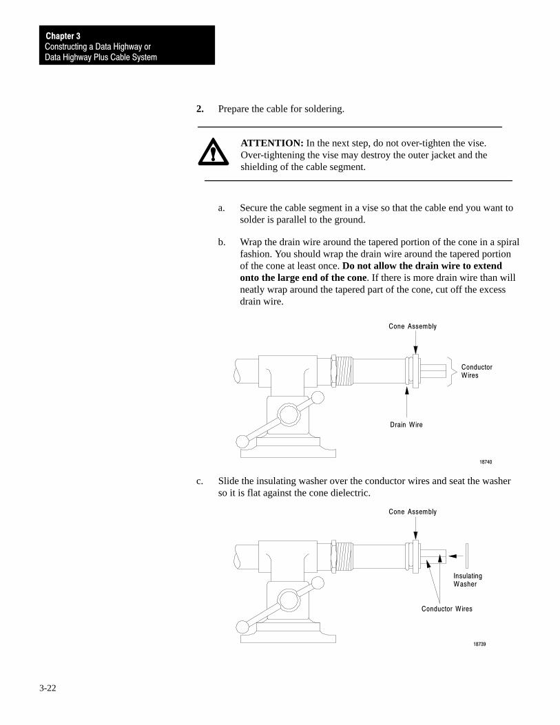
2. Prepare the cable for soldering.
ATTENTION: In the next step, do not over-tighten the vise.Over-tightening the vise may destroy the outer jacket and theshielding of the cable segment.
a. Secure the cable segment in a vise so that the cable end you want tosolder is parallel to the ground.
b. Wrap the drain wire around the tapered portion of the cone in a spiralfashion. You should wrap the drain wire around the tapered portionof the cone at least once. Do not allow the drain wire to extendonto the large end of the cone. If there is more drain wire than willneatly wrap around the tapered part of the cone, cut off the excessdrain wire.
ConductorWires
Drain Wire
Cone Assembly
18740
c. Slide the insulating washer over the conductor wires and seat the washerso it is flat against the cone dielectric.
Conductor Wires
Cone Assembly
InsulatingWasher
18739

Constructing a Data Highway orData Highway Plus Cable System
Chapter 3
3-23
d. Cut the blue conductor wire and the clear conductor wire toapproximately 0.35 inch (8.9 mm), as measured from the outsidesurface of the insulating washer.
Cone Assembly
InsulatingWasher
18741
8.89mm(0.35")
ConductorWires
e. Using wire strippers, strip approximately 0.10 inch (2.5 mm) of insulation off the end of the blue conductor wire.
f. Using wire strippers, strip approximately 0.20 inch (5.0 mm) of insulation off the end of the clear conductor wire.
5.0mm(0.2")
Clear Conductor Wire
Blue Conductor Wire
2.5mm(0.1")Insulation
InsulatingWasher
ConeAssembly
10807B
3. Solder the connector wires.
a. Bend the clear conductor wire so that it is at a right angle to the blueconductor wire.
ClearConductor Wire
BlueConductor Wire
ConeAssembly 18732

Chapter 3Constructing a Data Highway or Data Highway Plus Cable System
3-24
b. Tin the end of the blue conductor wire with a light coating of solder.
ATTENTION: To avoid burning yourself, allow the wire and solderto cool to room temperature before proceeding to the next step.
c. Push the notched insert onto the blue conductor wire so that the insertis flush against the insulating washer. The clear conductor wire fitsinto the notch in the end of the insert.
d. Using needlenose pliers, grasp the point of the pin and slip the largeend of the pin over the end of the blue conductor wire.
ClearConductor Wire
BlueConductor Wire
NotchedInsert
19604
Pin
InsulatingWasher
e. Keeping the pin seated evenly against the notched insert, heat thelarge end of the pin with a soldering pencil and apply a bead ofsolder through the hole in the large end of the pin.
ATTENTION: To avoid burning yourself, allow the pin and solderto cool to room temperature before proceeding to the next step.
f. Carefully remove any excess solder from the outside of the pin.

Constructing a Data Highway orData Highway Plus Cable System
Chapter 3
3-25
g. Slide the pin dielectric over the pin assembly.
BlueConductor Wire
18731
Hole in LargeEnd of Pin
Pin Dielectric
h. Slide the shield over the pin assembly and seat the shield against theinsulating washer. Make sure the clear conductor wire extendsthrough the notch in the large end of the shield.
i. Wrap the clear conductor wire around the groove in the shield.
j. Solder the clear conductor wire to the shield, making sure the solderflows well to produce a good connection. Do not allow the solder orthe wire to extend above the ridges of the shield.
Clear Conductor Wire
Shield
Ridge of Shield
Groove in ShieldInsulatingWasher
10808B
ATTENTION: To avoid burning yourself, allow the shield andsolder to cool to room temperature before proceeding to thenext step.
k. Carefully remove any excess solder from the surface of the shield.

Chapter 3Constructing a Data Highway or Data Highway Plus Cable System
3-26
4. Install the jack or plug connector.
a. Slip the shield dielectric over the shield assembly.
Shield
Shield Dielectric
18738
b. Push the connector body over the shield dielectric and engage thethreads of the wrench crimp nut.
ATTENTION: In the next step, be sure to adhere to the torquespecification. Over-tightening the crimp nut may damage theconnector, and under-tightening the crimp nut may create a looseconnection on the shielding.
c. Tighten the wrench crimp nut to 30-40 lbs-in (3.4-4.5 N-m).
Now that the connector body is assembled, you must check for electricalcontinuity as explained in the next procedure. Do not remove the cable segmentfrom the vise.

Constructing a Data Highway orData Highway Plus Cable System
Chapter 3
3-27
Test the Connector for Electrical ContinuityAfter you have assembled the connector body, check for any electrical shortsthat exist in the connector. To do this, use a multimeter to measure the resistancebetween the following points:
connector body and pin
pin and shield
shield and connector body
Connector Body
Pin
Plug Connector(end view) Jack Connector
(end view)
Test Connector Body and Pin
Pin
Shield
Plug Connector(end view) Jack Connector
(end view)
Test Pin and Shield
Shield
Connector Body
Plug Connector(end view) Jack Connector
(end view)
Test Shield and Connector Body11614
Chapter 3Constructing a Data Highway or Data Highway Plus Cable System
3-28
If the readings you obtain indicate that no shorts exist, you are ready toconnect the cable segments as explained next in this chapter.
If the readings you obtain indicate a short exists, disassemble the electricalconnector and the station connector and try to locate and correct the short.Check for frayed wire or wire fragments at each end of the wire. Check theresistances again.
If the resistance readings: Then:
Indicate there are no shorts Attach the dropline to the trunkline. Refer to the appropriatesection later in this chapter.
Indicate that a short exists The short is probably inside the dropline cable. Discard thedropline cable and attach the electrical connector to a new pieceof cable. You may remove the connector from the discardeddropline and reuse it on the new dropline.

Constructing a Data Highway orData Highway Plus Cable System
Chapter 3
3-29
Connect the Cable SegmentsOnce you have soldered the connectors to the dropline and trunkline segments,you must link these cable segments together. To do this, use the T-connectorfrom the connector kit.
Use Figure 3.6 for reference when connecting the cable segments.
Figure 3.6Connect the trunkline and droplines.
Plug Connector
Jack Connector
TrunklineSegment
T - connector
T - connector
TrunklineSegment
Jack Connector
Dropline
TrunklineSegment
T - connector
Dropline
11617

Chapter 3Constructing a Data Highway or Data Highway Plus Cable System
3-30
Figure 3.7 shows a more detailed view of the attachments to the T-connector.
Figure 3.7Attachments to the T�connector.
JackLeg
JackLeg
Plug ConnectorPlug Connector
Plug Leg
Jack Connector
Trunkline Segment
11618
1. Attach the jack connector of one trunkline segment to the plug leg of theT-connector.
2. Attach the plug connector of the other trunkline segment to one of the jacklegs of the T-connector.
3. Attach the plug connector of the dropline to the other jack leg of theT-connector.
4. Repeat steps 1 through 3 for other droplines and trunkline segments.
After all of the droplines and trunkline segments have been connected together,you must install a terminator at each end of the trunkline. Refer to the nextprocedure for instructions.
Terminate the TrunklineThe T-connectors on the ends of the trunkline have a dropline and only onetrunkline segment connected to each of them. This leaves two open, orunterminated, ends on the trunkline. Signals transmitted along the DH cablecould reflect off these unterminated ends and interfere with transmissions.
To minimize signal reflections from the ends of the trunkline, you must attachterminators (Figure 3.8) to the first and last T-connectors on the trunkline. (Theterms ‘‘first” and ‘‘last” refer to the physical location along the trunkline.)

Constructing a Data Highway orData Highway Plus Cable System
Chapter 3
3-31
Figure 3.8Install terminators to the first and last nodes.
Plug Terminator Jack Terminator11608
Use Figure 3.9 for reference when installing the trunkline terminators.
Figure 3.9Terminate the trunkline.
Plug Terminator
TrunklineSegment
Jack Connector
Dropline
TrunklineSegment
Dropline
11621
1. Attach the plug terminator to the T-connector jack leg that does not havea trunkline segment connected to it.
2. Attach the jack terminator to the T-connector that does not have atrunkline segment connected to its plug leg.

Chapter 3Constructing a Data Highway or Data Highway Plus Cable System
3-32
If you choose, you may construct your DH+ network using a daisy chainconfiguration, as shown below.
Node Node Node Node
18768
To make daisy chain DH+ connections, connect the twinaxial cable to thecorresponding DH+ connector terminals on the terminal block of both devices(Figure 3.10).
Figure 3.10Terminal connections when nodes are daisy chained.
Clear
Drain
Blue
Clear
Drain
Blue
Twinaxialcable
TerminatingResistor
Clear
Drain
Blue
Clear
Drain
Blue
Twinaxialcable
TerminatingResistor
18769
After connecting all nodes to the DH+ network, you must install a 150 ohm 1/4watt terminating resistor at each end of the network (Figure 3.10). Some DH+modules provide an internal resistor option for this purpose. Refer to the manualfor the particular module you are using to see if this option is available.
Construct a Network Using aDaisy Chain Configuration (DH+ Only)

Constructing a Data Highway orData Highway Plus Cable System
Chapter 3
3-33
After your DH or DH+ network has been operating for some time, you may findit necessary to add or remove nodes from the network. This section explainshow to modify a network constructed with droplines and station connectors toaccommodate these changes.
In this section we explain how to:
add a node to DH and DH+
remove a node from DH and DH+
Important: This section only describes the changes that must be made to thecable system when you reconfigure the nodes. You may need to makeprogramming changes at some or all of the nodes so that the nodes cancommunicate properly after they have been reconfigured. Refer to yourinterface user’s manual for information on how to make programming changes.
Add a Node to DH and DH+
To add a node to a DH and DH+ network, follow these steps:
1. Obtain enough connectors and twinaxial cable to construct the additionaldropline and trunkline segments necessary for the new node.
2. Attach the electrical connector to the dropline as explained in the section‘‘Attach an Electrical Connector to the Dropline” earlier in this chapter.
3. Install the station connector as explained earlier in this chapter in thesection ‘‘Install the 1770-SC Station Connector” or ‘‘Install the 1770-XGConnector Kit.”
ATTENTION: The next step will stop all network communication.Individual nodes can continue to perform their independentfunctions, but disconnecting all nodes may result in the loss oftransmitted messages and the activation of REMOTE/LOCALFAULT indicators by the node interface modules.
4. At each node on the network, disconnect the electrical connector from theinterface module on the node.
5. Connect the new dropline and trunkline segments to the existing network.
Important: If you add the new trunkline segment to either the first or lastconnectors on the network, you must move the terminating resistor to the newtermination point on the trunkline.
6. Reconnect all droplines to the node interface modules.
Reconfigure a NetworkConstructed with Droplinesand Station Connectors (If Necessary)
Chapter 3Constructing a Data Highway or Data Highway Plus Cable System
3-34
Remove a Node from DH and DH+
The procedure for removing a node from a DH and DH+ network depends uponwhether you want to remove the node permanently or temporarily.
In either case, you do not need to remove power from an Allen-Bradleyprogrammable controller before disconnecting its node from the network. Theprogrammable controller continues to control its outputs in a normal fashioneven after it is disconnected from the network. Disconnection, however, maycause the loss of some transmitted messages and the activation ofREMOTE/LOCAL FAULT indicators by the node interface module.
Temporarily Remove a Node from DH or DH+You may want to temporarily remove a node from the network whileperforming maintenance functions on the node. If the maintenance you want toperform can be done quickly (such as inserting a new communication adaptermodule at the node,) simply unplug the electrical connector from the nodeinterface module.
Important: A disconnected dropline may act as an antenna for signal noise.If noise is a problem, temporarily disconnect the dropline from the trunkline.
Permanently Remove a Node From a Network Constructed with a 1770-SCStation Connector To permanently remove a node linked to a network by a 1770-SC stationconnector, follow these steps.
1. Disconnect the dropline conductor wires from terminals 6 and 8 of thestation connector terminal block.
2. Disconnect the drain wire from terminal 7 of the station connectorterminal block.
3. Loosen the cable clamp on the dropline and pull the dropline out of thestation connector.

Constructing a Data Highway orData Highway Plus Cable System
Chapter 3
3-35
4. Insert a cable clamp plug into the cable clamp where the dropline used tobe. Secure the cable clamp plug by tightening the cable clamp.
Trunkline OutTrunkline In
Cable Clamp
Ground Wire(green)
#12 ga. to Earth GroundDropline Cable
Toor Data Highway Plus
11276
Data Highway

Chapter 3Constructing a Data Highway or Data Highway Plus Cable System
3-36
Permanently Remove an Intermediate Node from a Network Constructedwith a 1770-XG Connector Kit
Important: An intermediate node is a node that is not the first or last node onthe trunkline.
To permanently remove an intermediate node from a network constructed with a1770-XG connector kit, follow these steps:
1. Disconnect both trunkline segments from the T-connector that links thenode you want to remove.
Plug Connector
Trunkline Segment
JackConnector
TrunklineSegment
Dropline ofNode to beDisconnected
T - Connector
11619

Constructing a Data Highway orData Highway Plus Cable System
Chapter 3
3-37
2. Connect the mating ends of the two trunkline segments you disconnectedfrom the T-connector.
Reconnect Trunkline Segments here
Trunkline Segment
TrunklineSegment
Dropline ofdisconnectedNode
T - Connector
11620
Remove
3. If possible, remove the T-connector and dropline from the site and storethem for future use.
Permanently Remove an End Node on a Network Constructed with a1770-XG Connector KitTo permanently remove an end node (either the first or last node on thetrunkline) linked to the network by a 1770-XG connector kit, follow these steps.
1. Disconnect the trunkline segment from the T-connector that is connectedto the node you want to remove.

Chapter 3Constructing a Data Highway or Data Highway Plus Cable System
3-38
2. Disconnect the jack terminator or plug terminator from the T-connector.
Plug Connector
TrunklineSegment
Dropline ofNode youwant to disconnect
T - Connector
11623
JackTerminator

Constructing a Data Highway orData Highway Plus Cable System
Chapter 3
3-39
3. Plug the terminator into the end of the trunkline segment that youdisconnected from the T-connector.
Plug Connectorr
TrunklineSegment
Dropline ofdiscardednode
T - Connector
11622
JackTerminatortor
ReconnectTerminator here
You may also removeunneeded Trunkline Segment
4. If possible, remove the T-connector and dropline from the site and storethem for future use.

Chapter
4
4-1
Data Highway II Overview
Read this chapter for information on:
the DH II cable system
how nodes communicate on DH II
communication between networks
communication with synchronous and asynchronous devices
related products and publications
The Allen-Bradley Data Highway II system is a Local Area Network (LAN).It connects programmable controllers, computers, and other devices so they cancommunicate and exchange data with one another. Cables are the physicalmeans of transmitting this data between nodes. On a DH II network, a node isa hardware interface.
Chapter Overview
The DH II Cable System

DH II OverviewChapter 4
4-2
Figure 4.1 shows an example of a DH II network.
Figure 4.1A typical DH II cable system.
PLC - 2 PLC - 3
To Data Highway Plus
1779-KP5/KP5R*
1779-KFL/KFLR*
1779-KMF/KMFR*
Computer Robot IBM-PC
Data Highway II
1779-KP2/KP2R* 1779-KP3/KP3R*
* An "R" in the product name denotes a redundant module. 18770
You can also order your DH II interface modules with a redundant-cablingoption. To use redundant cabling, you must choose this option for all theinterface modules on your network.
Redundant cabling modules allow you to run a second trunkline cable betweenyour modules. DH II redundant interface modules send signals down bothcables. The receiving module determines which of the two signals is a bettersignal. By comparing the quality of the signals on each cable, the module canuse the best signal possible. There will also be a backup cable should one cablefail.

DH II OverviewChapter 4
4-3
Figure 4.2 shows a typical redundant cabling configuration.
Figure 4.2A redundant cabling configuration.
RedundantNode
Interface
Dropline
Dropline
RedundantNode
Interface
Dropline
Dropline
RedundantNode
Interface
Dropline
Dropline
Trunkline Trunkline Trunkline Trunkline
Trunkline Trunkline TrunklineTrunkline
Cable System A
Cable System B16046
Tap Tap Tap
TapTapTap
For more information on DH II interface modules, refer to the Data Highway IILocal Area Network Overview (publication 1779-2.10).

DH II OverviewChapter 4
4-4
DH II uses token-passing protocol to allow nodes on the network to transmitmessages over the cables. With token-passing protocol, only the nodepossessing the token can transmit messages. As long as a node possesses thetoken, it is the master.
When a node has sent all of its messages or used all of its token-hold time, itpasses the token to the node with the next highest address. Token passingcontinues in this manner until the token is passed to the node with the lowestaddress. When the node with the lowest address is finished with the token, thecycle begins again.
On DH II, the interface modules control access to the network locally. Thismeans if one module faults, the other modules continue to communicate on thenetwork.
Through interface modules, nodes on a DH II network can communicate withnodes on a DH+ network.
To communicate between nodes on a DH II network and a DH+ network, use1779-KP5 Data Highway II/Data Highway Plus Interface Module. Refer to theData Highway II Local Area Network Overview (publication 1779-2.10) formore information.
A message from a node on one network to a node on another network usesmessage transmission time in both networks. To achieve the best networkperformance, configure each network so that a minimum of messages crossbetween them. You can do this by grouping stations that need to frequentlycommunicate with each other on the same network.
In many applications, nodes on a DH II network need to communicate withdevices such as:
computers
color graphic terminals
dumb terminals
robots
computerized numerical controls (CNC)
motion controllers
How Nodes Communicate on DH II
Communication BetweenNetworks
Communication withSynchronous andAsynchronous Devices

DH II OverviewChapter 4
4-5
To connect these devices to a DH II interface module, you must provide yourown cable. The interface module and cable you use depends upon the type ofdevice you are connecting.
For example, an asynchronous device that communicates through an RS-232-Cport would use RS-232-C cable to connect to a DH II Asynchronous DeviceInterface (1779-KFL, -KFLR).
Refer to Appendix A for wiring diagrams for several devices.
You must also provide a driver program to allow your device to communicatewith DH II.
For more information on DH II interface modules, software interfaces, and thedevices you can connect to them, refer to the Data Highway II OverviewProduct Data (publications 1779-2.10).
In this chapter we provided you with a general overview of the DH II cable system and offered other information resources. You are now readyto plan your network. Refer to Chapter 5.
Important: Chapter 5 provides important specifications, guidelines andprecautions that you need to know before you construct your DH II network.Be sure to read Chapter 5 before beginning any construction of yourcable system.
Chapter
5
5-1
Planning a Data Highway II Cable System
This DH II cable system gives you flexibility to design a communicationnetwork that is tailored to your particular needs. To take full advantage of thisflexibility, you should spend sufficient time planning how to install your cablesystem before assembling any of your hardware.
Important: This chapter provides important specifications, guidelines andprecautions that you need to know before you construct your DH II network.Read this chapter carefully before beginning any construction of yourcable system.
After reading this chapter, you will be ready to begin constructing your DH IIcable system. This chapter provides information to help you plan a DH II cablesystem, including:
components of a DH II network
necessary tools
guidelines for determining cable length
selecting the number of taps
harmful environmental factors
After reading this chapter, consult schematic and engineering drawings of yourplant facility for specific information concerning the best location for installingyour cable network.
In this section we explain the functions and specifications of the followingcomponents of a DH II network:
trunkline
droplines and taps
terminators
Chapter Overview
Components of a DH IINetwork
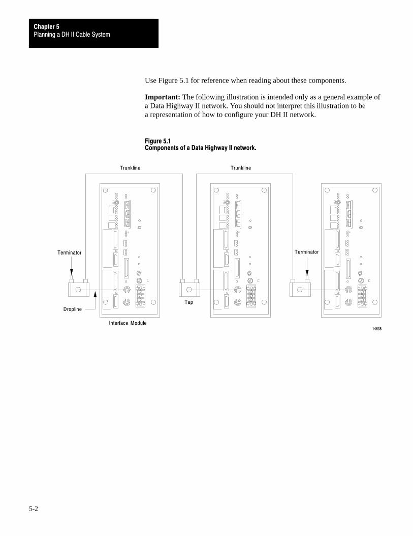
Planning a DH II Cable SystemChapter 5
5-2
Use Figure 5.1 for reference when reading about these components.
Important: The following illustration is intended only as a general example ofa Data Highway II network. You should not interpret this illustration to bea representation of how to configure your DH II network.
Figure 5.1Components of a Data Highway II network.
Terminator
Dropline
Interface Module
Tap
Trunkline Trunkline
Terminator
14638

Planning a DH II Cable SystemChapter 5
5-3
Trunkline
The trunkline is the bus, or the central part of the network cable system. Thelength of the trunkline on your network depends upon the number of nodes yourequire, however, the maximum length is 8,000 feet (2440 meters).
Each node on the trunkline reduces the 8,000 feet (2440 meters) of availabletrunkline length by 75 feet (22.9 meters).
For example, if your network requires 20 nodes, the maximum total length ofyour trunkline is:
8,000 - (20 x 75) = 6,500 feet or
2440 - (20 x 22.9) = 458 meters.
The trunkline on your network is divided into several segments by taps. Thecable length of the trunkline is equal to the total cable length of the trunklinesegments. Each cable segment must be at least 30 feet (9.2 meters) in lengthbetween taps.
The trunkline is constructed of RG-11 type coaxial cable (Allen-Bradley partno. 94082901). This cable has a foil shield and a braided shield. (Figure 5.2).
Figure 5.2The RG�11 type coaxial cable has a foil shield and a braided shield.
Insulating Jacket
Braided Shield Foil Shield
Dielectric
InnerConductor
16047

Planning a DH II Cable SystemChapter 5
5-4
You must order RG-11 type coaxial cable through the following manufacturers.
Table 5.AManufacturers and part numbers for RG�11 type coaxial cable.
Manufacturer: Part Number:
Allen�Bradley 94082901
Carol/Astro C0996 / 20�111�E
Alpha 9825C
Times AA�5066
For extremely harsh environments, order cable with a HALAR* jacket throughthe following manufacturers.
Manufacturer: Part Number:
Allen�Bradley 400037401
Carol/Astro 20�111�H
*HALAR is a registered trademark of Ausimont Chemical.
These manufacturers can be contacted at the following addresses.
Allen-Bradley Company747 Alpha DriveHighland Heights, OH 44143
Alpha Wire Corp.711 Lidgerwood Ave.Elizabeth, NJ 07207
Carol/Astro Wire & Cable Corp.50 Gardner St.P.O. Box 246Worchester, MA 01613
Times Fiber Communications Inc.358 Hall Ave.P.O. Box 384Wallingford, CT 06492
For information on installing the trunkline, refer to Chapter 6.

Planning a DH II Cable SystemChapter 5
5-5
Droplines and Taps
Droplines connect individual nodes to the trunkline. They are two feet long andconnect directly to the node interface module. The catalog number is 1779-XP.
Important: The droplines on your DH II network must be 2 feet (61 cm) in length.
Taps connect the droplines to the trunkline and are supplied with the droplines.A trunkline segment must be at least 30 feet (9.2 meters) long between taps.
When you order a dropline and tap, you also receive two cable plugs. Theseplugs are installed on the ends of trunkline segments and allow the segments toplug into the tap.
Figure 5.3 shows the components of a tap.
Figure 5.3Components of a tap.
Cable Plugs (2)
BodyPinSleeve
Tap
Trunkline Jack
MountingHole Dropline Jack
MountingHole
Cap
Straight Plug Right-angle Plug
Dropline Cable Assembly
12638
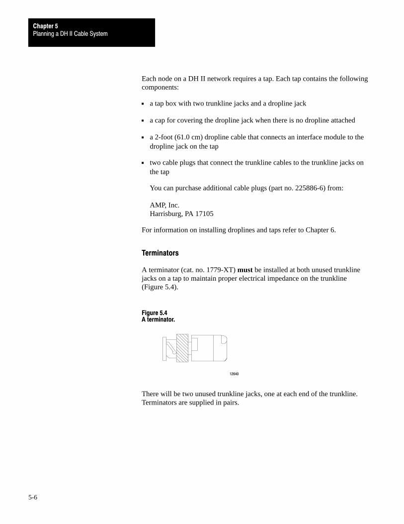
Planning a DH II Cable SystemChapter 5
5-6
Each node on a DH II network requires a tap. Each tap contains the followingcomponents:
a tap box with two trunkline jacks and a dropline jack
a cap for covering the dropline jack when there is no dropline attached
a 2-foot (61.0 cm) dropline cable that connects an interface module to thedropline jack on the tap
two cable plugs that connect the trunkline cables to the trunkline jacks onthe tap
You can purchase additional cable plugs (part no. 225886-6) from:
AMP, Inc.Harrisburg, PA 17105
For information on installing droplines and taps refer to Chapter 6.
Terminators
A terminator (cat. no. 1779-XT) must be installed at both unused trunklinejacks on a tap to maintain proper electrical impedance on the trunkline(Figure 5.4).
Figure 5.4A terminator.
12640
There will be two unused trunkline jacks, one at each end of the trunkline.Terminators are supplied in pairs.
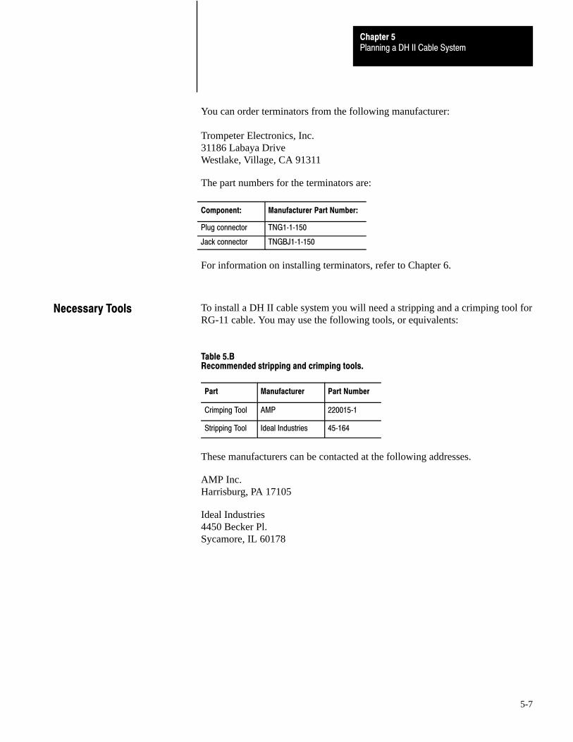
Planning a DH II Cable SystemChapter 5
5-7
You can order terminators from the following manufacturer:
Trompeter Electronics, Inc.31186 Labaya DriveWestlake, Village, CA 91311
The part numbers for the terminators are:
Component: Manufacturer Part Number:
Plug connector TNG1�1�150
Jack connector TNGBJ1�1�150
For information on installing terminators, refer to Chapter 6.
To install a DH II cable system you will need a stripping and a crimping tool forRG-11 cable. You may use the following tools, or equivalents:
Table 5.BRecommended stripping and crimping tools.
Part Manufacturer Part Number
Crimping Tool AMP 220015�1
Stripping Tool Ideal Industries 45�164
These manufacturers can be contacted at the following addresses.
AMP Inc.Harrisburg, PA 17105
Ideal Industries4450 Becker Pl.Sycamore, IL 60178
Necessary Tools

Planning a DH II Cable SystemChapter 5
5-8
The trunkline on your network is divided into several segments by taps.The cable length of the trunkline is equal to the total cable length of thetrunkline segments.
Important: When determining the cable length of trunkline segments, be sureto measure the actual cable path as it is routed in your network. Be sure toconsider vertical dimensions as well as horizontal dimensions. You shouldalways calculate the three-dimensional path distance when determiningcable lengths.
How you configure your network determines the lengths of all trunklinesegments.
Important: Remember that the maximum cable length of the trunkline is 8,000feet (2440 meters), and that each node on the trunkline reduces the 8,000 feet(2440 meters) of available cable by 75 feet (22.9).
Also remember that cable segments must be at least 30 feet (9.2 meters) inlength between taps.
You should also plan your trunkline cable routing so that the cable bend-radiusis not less than 6 inches (15.2 cm).
Figure 5.5The bend�radius for the trunkline cable should not be less than 6 inches (15.2 cm).
6 inch
12642
Guidelines for DeterminingCable Length
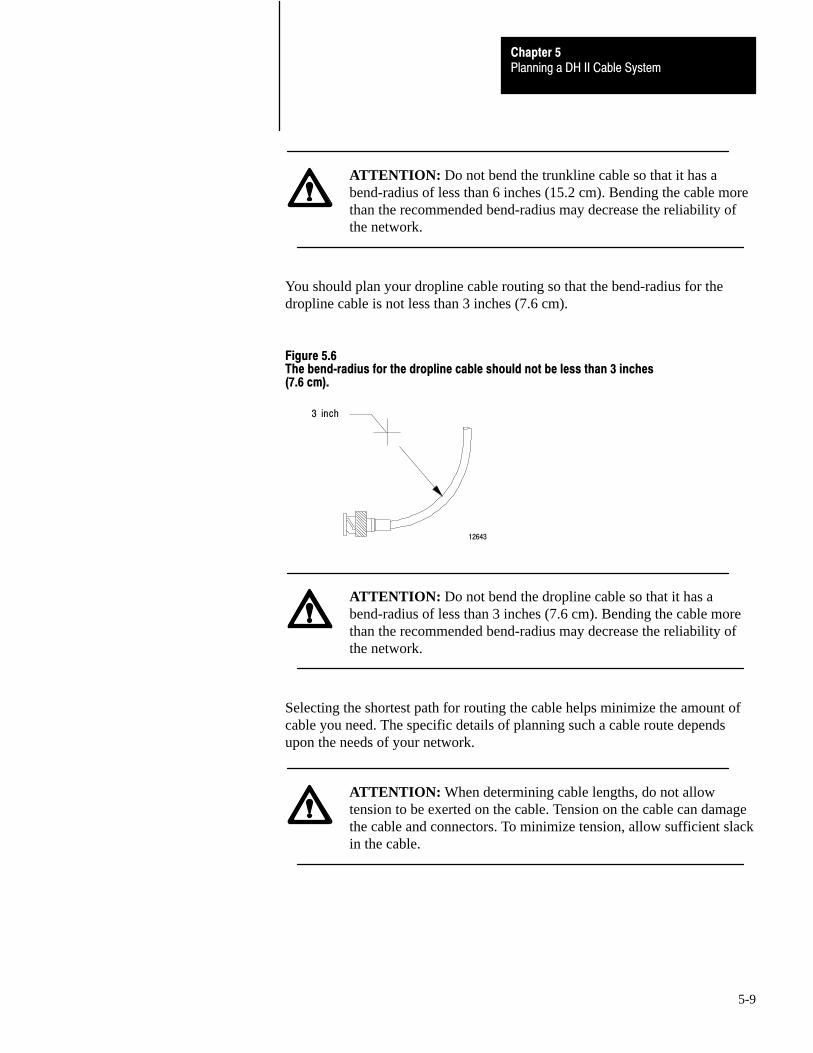
Planning a DH II Cable SystemChapter 5
5-9
ATTENTION: Do not bend the trunkline cable so that it has abend-radius of less than 6 inches (15.2 cm). Bending the cable morethan the recommended bend-radius may decrease the reliability ofthe network.
You should plan your dropline cable routing so that the bend-radius for thedropline cable is not less than 3 inches (7.6 cm).
Figure 5.6The bend�radius for the dropline cable should not be less than 3 inches(7.6 cm).
3 inch
12643
ATTENTION: Do not bend the dropline cable so that it has abend-radius of less than 3 inches (7.6 cm). Bending the cable morethan the recommended bend-radius may decrease the reliability ofthe network.
Selecting the shortest path for routing the cable helps minimize the amount ofcable you need. The specific details of planning such a cable route dependsupon the needs of your network.
ATTENTION: When determining cable lengths, do not allowtension to be exerted on the cable. Tension on the cable can damagethe cable and connectors. To minimize tension, allow sufficient slackin the cable.

Planning a DH II Cable SystemChapter 5
5-10
You must install a tap for each node on the network.
In addition, if you plan to add nodes at a later date, you should install taps forthese additional nodes when you install the initial cable system. This will helpavoid the disruption of recabling after the network is in operation.
The I/O raceway layout of a system is reflective of where the different types ofI/O modules are placed in an I/O chassis. Therefore, you should determine I/Omodule placement prior to any layout and routing of wires. However, whenplanning your I/O module placement, segregate the modules based upon theconductor categories published for each I/O module so that you can follow theseguidelines. These guidelines coincide with the guidelines for “the installation ofelectrical equipment to minimize electrical noise inputs to controllers fromexternal sources” in IEEE standard 518-1982.
Categorize Conductors
Segregate all wires and cables into the three categories shown in Table 5.C. Refer to the publication for each I/O module for the conductorcategory classification of each I/O line.
Selecting the Number ofTaps
I/O Raceway LayoutConsiderations

Planning a DH II Cable SystemChapter 5
5-11
Table 5.CFollow these guidelines for grouping conductors
Group conductor cables fitting this description: Into thiscategory:
Examples:
Control & ac Power - high�power conductors that are moretolerant of electrical noise than category 2 conductors andmay also cause more noise to be picked up by adjacentconductors.
• corresponds to NEC article�725 class 1
• corresponds to IEEE levels 3 (low susceptibility) & 4 (power)
Category 1 • ac power lines
• high�power digital ac I/O lines - to connect ac I/Omodules rated for high power and high noiseimmunity.
• high�power digital dc I/O lines - to connect dc I/Omodules rated for high power or with input circuitswith long time�constant filters for high noise rejection.They typically connect devices such as hard�contactswitches, relays, and solenoids.
Signal & Communication - low�power conductors that areless tolerant of electrical noise than category 1 conductorsand should also cause less noise to be picked up byadjacent conductors (they connect to sensors andactuators relatively close to the I/O modules).
• corresponds to NEC article�725 classes 2 & 3
• corresponds to IEEE levels 1 (high susceptibility) & 2 (medium susceptibility)
Category 2 • analog I/O lines and dc power lines for analogcircuits
• low�power digital ac/dc I/O lines - to connect to I/Omodules that are rated for low power such aslow�power contact�output modules.
• low�power digital dc I/O lines - to connect dc I/Omodules that are rated for low power and have inputcircuits with short time�constant filters to detect shortpulses. They typically connect to devices such asproximity switches, photo�electric sensors, TTLdevices, and encoders.
• communication cables (remote I/O, extended�localI/O, DH+ , DH�485, RS�232�C, RS�422, RS�423cables) - to connect between processors or to I/Oadapter modules, programming terminals,computers, or data terminals.
Intra�enclosure - Interconnect the system componentswithin an enclosure
• corresponds to NEC article�725 classes 2 & 3
• corresponds to IEEE levels 1 (high susceptibility) & 2 (medium susceptibility)
Category 3 • low�voltage dc power cables - provide backplanepower to the system components
• communication cables - to connect between systemcomponents within the same enclosure
NOTE: Remote I/O, DH, and DH+ networks must be made of catalog number 1770�CD cable or a cable from the approved vendor list.
DH�485 networks must be made of a cable from the approved vendor list.

Planning a DH II Cable SystemChapter 5
5-12
Route Conductors
To guard against coupling noise from one conductor to another, follow thegeneral guidelines shown in Table 5.D when routing wires and cables (bothinside and outside of an enclosure). Where it is stated that cables must be inseparate raceways, they can be routed in the same ladder or trough if barriersare used as required and defined by NEC to provide the separation specified inTable 5.D. Use the spacing given in these general guidelines with the followingexceptions:
where connection points (for conductors of different categories) on enddevices are closer together than the specified spacing
application-specific configurations for which the spacing is described in apublication for that specific application

Planning a DH II Cable SystemChapter 5
5-13
Table 5.DFollow these guidelines for routing cables
Route this categoryof conductor cables:
According to these guidelines:
Category 1 These conductors can be routed with machine power conductors of up to 600V ac (feeding up to 100 hpdevices) if this does not violate local codes.
Category 2 General guidelines - these guidelines apply in all cases.
• If it must cross power feed lines, it should do so at right angles.
• Route at least 5 ft from high�voltage enclosures, or sources of rf/microwave radiation.
• If the conductor is in a metal wireway or conduit, each segment of that wireway or conduit must be bondedto each adjacent segment so that is has electrical continuity along its entire length, and must be bonded tothe enclosure at the entry point.
For Unrestricted Applications - these guidelines apply unless you can meet the restricted�applicationguidelines.
• Properly shield (where applicable) and route in a raceway separate from category 1 conductors. They canbe routed in the same ladder or trough with category 1 conductors if barriers are used as required by NECto provide the separation specified in the following items.
• If in a contiguous metallic wireway or conduit, route at least 0.08m (3 in) from category 1 conductors of lessthan 20A; 0.15m (6 in) from ac power lines of 20A or more, but only up to 100 kVA; 0.3m (1 ft) from acpower lines of greater than 100 kVA.
• If not in a contiguous metallic wireway or conduit, route at least 0.15m (6 in) from category 1 conductors ofless than 20A; 0.3m (1 ft) from ac power lines of 20A or more, but only up to 100 kVA; 0.6m (2 ft) from acpower lines of greater than 100 kVA.
For Restricted Applications - remote I/O, DH, DH+, and DH�485 cables can be bundled together withcategory 1 conductors in a molded composite cable if the application can meet these guidelines.
• All category 2 conductors must be bundled together inside a common grounded 95% braided shield (with100% aluminum tape shield) to separate them from the category 1 conductors in the larger bundle.
• Category 1 conductors must carry no more than 15A maximum at 120V maximum to power supply loads,I/O circuit non�inductive loads, or I/O circuit inductive loads that are not switched by hard contacts.
• The total cable length of the remote I/O, DH, DH+, or DH�485 link must be limited to 456 meters (1,500 ft)maximum.
Category 3 Route conductors external to all raceways in the enclosure or in a raceway separate from any category 1conductors with the same spacing listed for category 2 conductors, where possible.
Article 300�3 of the National Electrical Code requires that all conductors (ac and/or dc) in the same raceway must be insulated for the highest voltage applied to any one of theconductors in the raceway.
Chapter
6
6-1
Constructing a Data Highway II Cable System
In this chapter we explain how to construct a DH II cable system, includinghow to:
install the taps
prepare the trunkline cable for installation
attach the trunkline cables and terminators to the tap
install the droplines
Important: Before you begin any procedure explained in this chapter, readChapter 5, ‘‘Planning a Data Highway II Cable System” for importantguidelines and precautions to consider when installing your cable network.
The first step in constructing your DH II cable system is to install the taps.When deciding where to mount the taps, follow these guidelines:
ATTENTION: Mount the tap so that the cap for the dropline jackcan hang from its chain freely without touching a conductive surface.If the cap for the dropline jack or its chain touches a conductivesurface, the reliability of the link could be significantly reduced.
Make sure the mounting location is convenient for your trunklinecable routing.
Make sure the mounting location does not cause the trunkline cablebend-radius to be less than 6 inches (15.2 cm).
Mount the tap at least 2 inches (5.1 cm) from the interface module to makesure the interface module has sufficient air flow for cooling.
Chapter Overview
Install the Taps

Constructing a DH II Cable SystemChapter 6
6-2
Mount the tap no more than 11 inches (28.0 cm) from the bottom or left sideof the interface module to make sure the dropline cable bend-radius is notless than 3 inches (7.6 cm).
Do not mount the tap in a position that routes the dropline cable over the acpower terminals on the interface module.
Do not allow the metal shell of the tap to touch a conductive surface.
If you are using a PLC-3 interface module (catalog numbers 1779-KP3 or1779-KP3R) you must mount the tap no more than 5 inches (12.7 cm) fromthe PLC-3 chassis. You can mount the tap on the side of the chassis only ifthe interface module is at the end of the chassis.
Figure 6.1 shows the dimensions of a tap.
Figure 6.1Dimensions of a tap.
25mm(1.0 in)
38mm(1.5 in)
54mm(2.1 in)
79mm(3.1 in)
89mm(3.5 in)
6mm(0.2 in)
Clearance Depth:77mm (5 in)
Use No. 5mounting bolts2 places
12644

Constructing a DH II Cable SystemChapter 6
6-3
Figure 6.2 shows a tap mounted below an interface module. The trunkline runsstraight through the side wall of the enclosure.
Figure 6.2A tap mounted below an interface module.
EnclosureWall
Dropline
Tap
12645
Interface Module

Constructing a DH II Cable SystemChapter 6
6-4
Figure 6.3 shows taps mounted on the side of an interface module.The trunkline cables run straight through the top of the enclosure.
Figure 6.3Taps mounted on the side of an interface module.
Top of Enclosure
DroplineTap
Redundant Interface Module
TapDropline
12646
If you do not connect a dropline to the tap, place the cap over the dropline jackon the front of the tap.
Put cap ondropline jack
12647
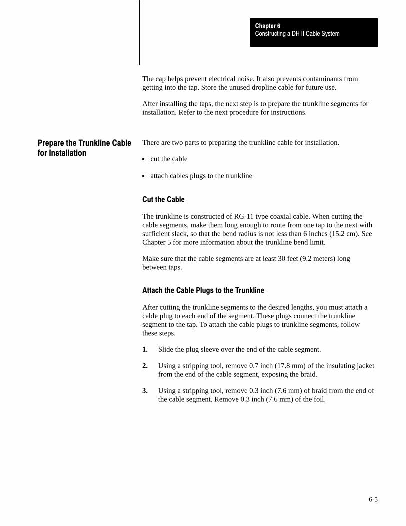
Constructing a DH II Cable SystemChapter 6
6-5
The cap helps prevent electrical noise. It also prevents contaminants fromgetting into the tap. Store the unused dropline cable for future use.
After installing the taps, the next step is to prepare the trunkline segments forinstallation. Refer to the next procedure for instructions.
There are two parts to preparing the trunkline cable for installation.
cut the cable
attach cables plugs to the trunkline
Cut the Cable
The trunkline is constructed of RG-11 type coaxial cable. When cutting thecable segments, make them long enough to route from one tap to the next withsufficient slack, so that the bend radius is not less than 6 inches (15.2 cm). SeeChapter 5 for more information about the trunkline bend limit.
Make sure that the cable segments are at least 30 feet (9.2 meters) longbetween taps.
Attach the Cable Plugs to the Trunkline
After cutting the trunkline segments to the desired lengths, you must attach acable plug to each end of the segment. These plugs connect the trunklinesegment to the tap. To attach the cable plugs to trunkline segments, followthese steps.
1. Slide the plug sleeve over the end of the cable segment.
2. Using a stripping tool, remove 0.7 inch (17.8 mm) of the insulating jacketfrom the end of the cable segment, exposing the braid.
3. Using a stripping tool, remove 0.3 inch (7.6 mm) of braid from the end ofthe cable segment. Remove 0.3 inch (7.6 mm) of the foil.
Prepare the Trunkline Cablefor Installation
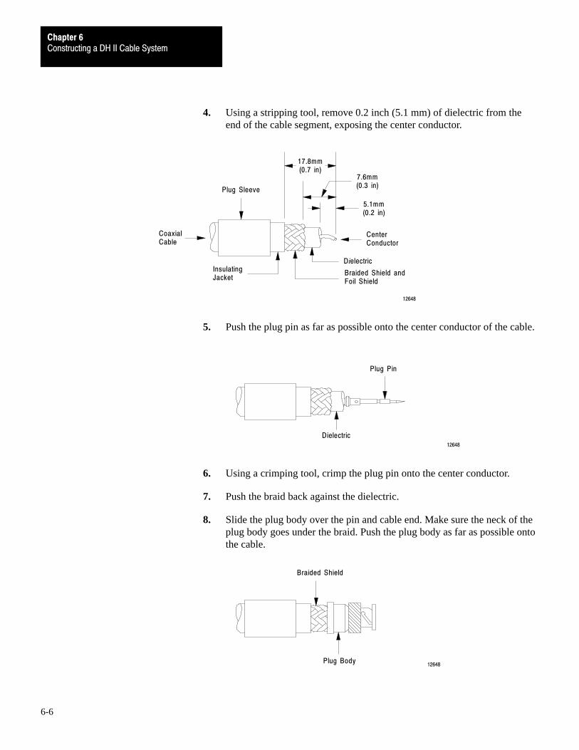
Constructing a DH II Cable SystemChapter 6
6-6
4. Using a stripping tool, remove 0.2 inch (5.1 mm) of dielectric from theend of the cable segment, exposing the center conductor.
5.1mm(0.2 in)
7.6mm(0.3 in)
17.8mm(0.7 in)
CenterConductor
Dielectric
Braided Shield andFoil Shield
InsulatingJacket
CoaxialCable
Plug Sleeve
12648
5. Push the plug pin as far as possible onto the center conductor of the cable.
Plug Pin
Dielectric12648
6. Using a crimping tool, crimp the plug pin onto the center conductor.
7. Push the braid back against the dielectric.
8. Slide the plug body over the pin and cable end. Make sure the neck of theplug body goes under the braid. Push the plug body as far as possible ontothe cable.
Braided Shield
Plug Body12648

Constructing a DH II Cable SystemChapter 6
6-7
9. Slide the plug sleeve over the braid until it butts up against the shoulder ofthe plug body.
10. Position the crimping tool over the plug sleeve as close to the plug bodyshoulder as possible and crimp the plug sleeve.
The next step is to attach the trunkline cables and terminators to the tap.Figure 6.4 shows an example of how to configure the cable segments, taps andterminators in a network.
Figure 6.4An example of how to configure your network.
Node
Tap Tap
Dropline(two feet)
Tap
Trunklines(longer than 30 feet)
Node Node
Terminator
Dropline(two feet)
Terminator
16048
Attach the Trunkline Cablesand Terminators to the Tap
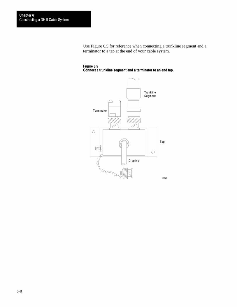
Constructing a DH II Cable SystemChapter 6
6-8
Use Figure 6.5 for reference when connecting a trunkline segment and aterminator to a tap at the end of your cable system.
Figure 6.5Connect a trunkline segment and a terminator to an end tap.
Dropline
TrunklineSegment
Terminator
Tap
12649

Constructing a DH II Cable SystemChapter 6
6-9
Use Figure 6.6 for reference when connecting two trunkline segments to a tap.
Figure 6.6Connect two trunkline segments to a tap.
Dropline
TrunklineSegment
Tap
12651
TrunklineSegment
Secure each cable in place with some form of strain-relief device to help makesure that:
you adhere to the bend-radius of the cable
the cable is not accidentally pulled out of its plug
When you connect a dropline to an interface module, make sure that thebend-radius is not less than 3 inches (7.6 cm). If there is not enough room toadhere to the bend-radius specification, you must remount the tap following theinstructions provided earlier in this chapter.
Install the Droplines

Constructing a DH II Cable SystemChapter 6
6-10
Plug the right-angle plug of the dropline into the DH II port on your interfacemodule. Then plug the other end of the dropline into the jack on the front ofthe tap.
Interface Module
TapCap and Chain
Right-angle plugDropline
Trunkline
12650
For more information on mounting and grounding a DH II interface module,refer to your interface module user’s manual.

Chapter
7
7-1
Data Highway�485 Overview
This chapter explains the following:
the DH-485 cable system how nodes communicate on DH-485
Cables are the physical means of transmitting data between nodes. On aDH-485 network, a node is a hardware interface.
The DH-485 network passes information between devices on the plant floor.The network monitors process parameters, device parameters, device status,process status, and application programs to support data acquisition, datamonitoring, program upload/download, and supervisory control.
1747-C11 Cable
1747-C11 Cable
1747-C11 Cable
LinkCoupler
1747-AIC
LinkCoupler
1747-AIC
LinkCoupler
1747-AIC
CommunicationCable
Belden #9842
Personal Computerwith 1784-KR Installed
SLC 500Controller
SLC 500Controller
SLC 500Controller
17680
Chapter Overview
The DH�485 Cable System

DH�485 OverviewChapter 7
7-2
DH-485 uses token-passing protocol to allow nodes on the network to transmitmessages over the cables. With token-passing protocol, only the nodepossessing the token can transmit messages. As long as a node possesses thetoken, it is the master.
When a node has sent all of its messages or used all of its token-hold time, itpasses the token to the node with the next highest address. Token passingcontinues in this manner until the token is passed to the node with the lowestaddress. When the node with the lowest address is finished with the token, thecycle begins again.
In this chapter we provided you with a general overview of the DH-485 cablesystem. You are now ready to plan your network. Refer to Chapter 8.
Important: Chapter 8 provides important specifications, guidelines andprecautions that you need to know before you construct your DH-485 network.Be sure to read Chapter 8 before beginning any construction of yourcable system.
How Nodes Communicate on DH�485

Chapter
8
8-1
Planning a Data Highway�485 Cable System
The DH-485 cable system gives you flexibility to design a communicationnetwork that is tailored to your particular needs. To take full advantage of thisflexibility, you should spend sufficient time planning how to install your cablesystem before assembling any of the hardware.
Important: This chapter provides important specifications, guidelines andprecautions that you need to know before you construct your DH-485 network.Read this chapter carefully before beginning any construction of your cablesystem.
After reading this chapter, you will be ready to start construction of yourDH-485 network. This chapter provides information to help you plan a DH-485cable system, including:
components of a DH-485 network
necessary tools
guidelines for determining cable length
selecting the number of link couplers
harmful environmental factors
After reading this chapter, consult schematic and engineering drawings of yourfacility for specific information concerning the best location for installing yourcable network.
Chapter Overview

Planning a DH�485 Cable SystemChapter 8
8-2
In this section we explain the functions and specifications of the followingcomponents of a DH-485 network:
trunkline
link couplers
Use Figure 8.1 for reference when reading about these components.
Figure 8.1An example DH�485 network.
1747-C11 Cable
1747-C11 Cable
1747-C11 Cable
LinkCoupler
1747-AIC
LinkCoupler
1747-AIC
LinkCoupler
1747-AIC
CommunicationCable
Belden #9842
Personal Computerwith 1784-KR Installed
SLC 500Controller
SLC 500Controller
SLC 500Controller
17680
Trunkline
Nodes on the trunkline are interconnected in a daisy chain fashion. The lengthof your trunkline depends upon the location of the nodes in your network,however, the maximum length is 4,000 feet (1220 meters).
Your cable system has the capability of interconnecting up to 32 devices.
Components of a DH�485Network

Planning a DH�485 Cable SystemChapter 8
8-3
The trunkline is constructed of Belden 9842 cable. This cable is jacketed andshielded, and consists of two twisted wire pairs and a drain wire. One pair oftwisted wires provides a balanced signal line, and one wire of the other pairserves as a common reference line between all nodes on the link. The shieldreduces the effect of electromagnetic noise from the industrial environment onthe link communications. The drain wire provides a shield connection point.
Refer to Chapter 9 for information on installing the trunkline.
Link Couplers
Link couplers connect devices to the DH-485 network. You must install a linkcoupler for each non-isolated node on the network. The type of coupler dependsupon the device that you are connecting to the DH-485 network.
Refer to Chapter 9 for information on installing link couplers.
To install a DH-485 network, you need the following tools for connecting thedata link components together. These tools are used to strip the cable and toattach the cable to the link couplers
Wire stripper
Wire cutter
The trunkline on your network is divided into several connected segments thatform a daisy chain configuration. The cable length of the trunkline is equal tothe total cable length of the trunkline segments.
Important: When determining the cable length of trunkline segments, be sureto measure the actual cable path as it is routed in your network. Be sure toconsider vertical dimensions as well as horizontal dimensions. You shouldalways calculate the three-dimensional path distance when determiningcable lengths.
How you configure your DH-485 network determines the lengths of alltrunkline segments.
Important: Remember that the maximum total cable length of the trunkline is4,000 feet (1220 meters).
Selecting the shortest path for routing the cable will help minimize the amountof cable you will need. The specific details of planning such a cable routedepends upon the needs of your network.
Necessary Tools
Guidelines for DeterminingCable Length

Planning a DH�485 Cable SystemChapter 8
8-4
ATTENTION: When determining cable lengths, do not allowtension to be exerted on the cable. Tension on the cable can damagethe cable and connectors. To minimize tension, allow sufficient slackin the cable.
You must install a link coupler for each non-isolated node on theDH-485 network.
If you plan to add non-isolated nodes at a later date, provide additional linkcouplers when you install the initial cable system. This will help avoid thedisruption of recabling after the network is in operation.
The I/O raceway layout of a system is reflective of where the different types ofI/O modules are placed in an I/O chassis. Therefore, you should determine I/Omodule placement prior to any layout and routing of wires. However, whenplanning your I/O module placement, segregate the modules based upon theconductor categories published for each I/O module so that you can follow theseguidelines. These guidelines coincide with the guidelines for “the installation ofelectrical equipment to minimize electrical noise inputs to controllers fromexternal sources” in IEEE standard 518-1982.
Categorize Conductors
Segregate all wires and cables into the three categories shown in Table 8.A. Refer to the publication for each I/O module for the conductorcategory classification of each I/O line.
Selecting the Number of Link Couplers
I/O Raceway LayoutConsiderations

Planning a DH�485 Cable SystemChapter 8
8-5
Table 8.AFollow these guidelines for grouping conductors
Group conductor cables fitting this description: Into thiscategory:
Examples:
Control & ac Power - high�power conductors that are moretolerant of electrical noise than category 2 conductors andmay also cause more noise to be picked up by adjacentconductors.
• corresponds to NEC article�725 class 1
• corresponds to IEEE levels 3 (low susceptibility) & 4 (power)
Category 1 • ac power lines
• high�power digital ac I/O lines - to connect ac I/Omodules rated for high power and high noiseimmunity.
• high�power digital dc I/O lines - to connect dc I/Omodules rated for high power or with input circuitswith long time�constant filters for high noise rejection.They typically connect devices such as hard�contactswitches, relays, and solenoids.
Signal & Communication - low�power conductors that areless tolerant of electrical noise than category 1 conductorsand should also cause less noise to be picked up byadjacent conductors (they connect to sensors andactuators relatively close to the I/O modules).
• corresponds to NEC article�725 classes 2 & 3
• corresponds to IEEE levels 1 (high susceptibility) & 2 (medium susceptibility)
Category 2 • analog I/O lines and dc power lines for analogcircuits
• low�power digital ac/dc I/O lines - to connect to I/Omodules that are rated for low power such aslow�power contact�output modules.
• low�power digital dc I/O lines - to connect dc I/Omodules that are rated for low power and have inputcircuits with short time�constant filters to detect shortpulses. They typically connect to devices such asproximity switches, photo�electric sensors, TTLdevices, and encoders.
• communication cables (remote I/O, extended�localI/O, DH+ , DH�485, RS�232�C, RS�422, RS�423cables) - to connect between processors or to I/Oadapter modules, programming terminals,computers, or data terminals.
Intra�enclosure - Interconnect the system componentswithin an enclosure
• corresponds to NEC article�725 classes 2 & 3
• corresponds to IEEE levels 1 (high susceptibility) & 2 (medium susceptibility)
Category 3 • low�voltage dc power cables - provide backplanepower to the system components
• communication cables - to connect between systemcomponents within the same enclosure
NOTE: Remote I/O, DH, and DH+ networks must be made of catalog number 1770�CD cable or a cable from the approved vendor list.
DH�485 networks must be made of a cable from the approved vendor list.
Route Conductors
To guard against coupling noise from one conductor to another, follow thegeneral guidelines shown in Table 8.B when routing wires and cables (bothinside and outside of an enclosure). Where it is stated that cables must be inseparate raceways, they can be routed in the same ladder or trough if barriersare used as required and defined by NEC to provide the separation specified inTable 8.B. Use the spacing given in these general guidelines with the followingexceptions:
where connection points (for conductors of different categories) on enddevices are closer together than the specified spacing

Planning a DH�485 Cable SystemChapter 8
8-6
application-specific configurations for which the spacing is described in apublication for that specific application
Table 8.BFollow these guidelines for routing cables
Route this categoryof conductor cables:
According to these guidelines:
Category 1 These conductors can be routed with machine power conductors of up to 600V ac (feeding up to 100 hpdevices) if this does not violate local codes.
Category 2 General guidelines - these guidelines apply in all cases.
• If it must cross power feed lines, it should do so at right angles.
• Route at least 5 ft from high�voltage enclosures, or sources of rf/microwave radiation.
• If the conductor is in a metal wireway or conduit, each segment of that wireway or conduit must be bondedto each adjacent segment so that is has electrical continuity along its entire length, and must be bonded tothe enclosure at the entry point.
For Unrestricted Applications - these guidelines apply unless you can meet the restricted�applicationguidelines.
• Properly shield (where applicable) and route in a raceway separate from category 1 conductors. They canbe routed in the same ladder or trough with category 1 conductors if barriers are used as required by NECto provide the separation specified in the following items.
• If in a contiguous metallic wireway or conduit, route at least 0.08m (3 in) from category 1 conductors of lessthan 20A; 0.15m (6 in) from ac power lines of 20A or more, but only up to 100 kVA; 0.3m (1 ft) from acpower lines of greater than 100 kVA.
• If not in a contiguous metallic wireway or conduit, route at least 0.15m (6 in) from category 1 conductors ofless than 20A; 0.3m (1 ft) from ac power lines of 20A or more, but only up to 100 kVA; 0.6m (2 ft) from acpower lines of greater than 100 kVA.
For Restricted Applications - remote I/O, DH, DH+, and DH�485 cables can be bundled together withcategory 1 conductors in a molded composite cable if the application can meet these guidelines.
• All category 2 conductors must be bundled together inside a common grounded 95% braided shield (with100% aluminum tape shield) to separate them from the category 1 conductors in the larger bundle.
• Category 1 conductors must carry no more than 15A maximum at 120V maximum to power supply loads,I/O circuit non�inductive loads, or I/O circuit inductive loads that are not switched by hard contacts.
• The total cable length of the remote I/O, DH, DH+, or DH�485 link must be limited to 456 meters (1,500 ft)maximum.
Category 3 Route conductors external to all raceways in the enclosure or in a raceway separate from any category 1conductors with the same spacing listed for category 2 conductors, where possible.
Article 300�3 of the National Electrical Code requires that all conductors (ac and/or dc) in the same raceway must be insulated for the highest voltage applied to any one of theconductors in the raceway.
Chapter
9
9-1
Constructing a Data Highway�485 Cable System
In this chapter we explain how to construct a Data Highway–485 cable system,including how to:
Install the trunkline and DH–485 nodes
Important: Before you begin any procedure explained in this chapter, readChapter 8, ‘‘Planning a DH–485 Cable System” for important guidelines andprecautions to consider when installing your cable network.
A DH–485 cable system is constructed in a daisy chain configuration. In thischapter we explain how to construct a DH–485 network. Non–isolated modulesrequire 1747–AIC link couplers to attach them to the network. The procedurefor installing the trunkline and DH–485 nodes involves the following steps:
prepare the cable wire
connect the cable to the DH–485 node
terminate the DH–485 shield
terminate the DH–485 network
Chapter Overview
Install the Trunkline and DH-485 Nodes

Constructing a DH�485 Cable SystemChapter 9
9-2
Figure 9.1 shows an example of a DH–485 network.
Figure 9.1An example DH-485 network.
1747-C11 Cable
1747-C11 Cable
1747-C11 Cable
LinkCoupler
1747-AIC
LinkCoupler
1747-AIC
LinkCoupler
1747-AIC
CommunicationCable
Belden #9842
Personal Computerwith 1784-KR Installed
SLC 500Controller
SLC 500Controller
SLC 500Controller
17680

Constructing a DH�485 Cable SystemChapter 9
9-3
Prepare the Cable Wire
Important: The wire colors of Belden 9842 cable have changed. Refer to thefollowing table to determine the corresponding wire colors of the previousversion of Belden 9842 and the current version of Belden 9842.
This wire or wire pair on the PREVIOUSversion of Belden 9842 cable:
Corresponds to this wire or wire pair on theCURRENT version of Belden 9842 cable:
Shield Shield
Black/White Blue-White Stripe/White-Blue Stripe
Black White-Blue Stripe
White Blue-White Stripe
Black/Red Orange-White Stripe/White-Orange Stripe
Black White-Orange Stripe
Red Orange-White Stripe
1. Cut the Belden 9842 cable to a length long enough to route from one nodeto the next. Refer to ‘‘Determining Cable Length” in Chapter 8 forguidelines for determining appropriate cable lengths.
2. Remove 1 inch (2.5 cm) of the PVC jacket from both ends of the cablesegment.
Important: In the next step, do not cut the drain wire.
3. Remove 1 inch (2.5 cm) of the braided shield under the PVC jacket.
4. Remove the foil that surrounds the twisted wire pairs and insulation.
5. Cut back the two white insulation strands.
6. Cut the white–blue stripe wire of the blue–white stripe/white–blue stripepair. It does not have a connection. Save the wire for a jumper.
7. Remove .25 inch (6.4 mm) of coating off the orange–white stripe/white–orange stripe wires. Do not tin the wire tips.
8. Remove .25 inch (6.4 mm) of coating off the white–blue stripe wire. Donot tin the wire tip.

Constructing a DH�485 Cable SystemChapter 9
9-4
Connect the Cable to the DH-485 Node
1. Connect the orange–white stripe wire of the orange–whitestripe/white–orange stripe pair to terminal 5 (A).
2. Connect the white–orange stripe wire of the orange–whitestripe/white–orange stripe pair to terminal 4 (B).
3. Connect the blue–white stripe wire of the blue–white stripe/white–bluestripe pair to terminal 3 (COM) .
4. Connect the shield/drain wire (non–jacketed) to Terminal 2 (SHLD).
6
5
4
3
2
1
Orange-WhiteStripe
Blue-WhiteStripe
Shield/Drain
TERM
A
B
COM
SHLD
CHS GND
Belden 9842 Cable
18760
White-OrangeStripe
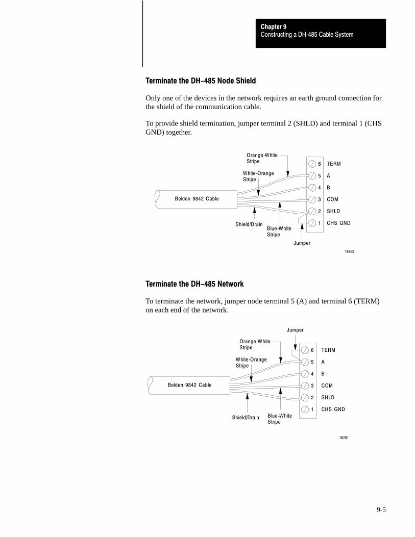
Constructing a DH�485 Cable SystemChapter 9
9-5
Terminate the DH-485 Node Shield
Only one of the devices in the network requires an earth ground connection forthe shield of the communication cable.
To provide shield termination, jumper terminal 2 (SHLD) and terminal 1 (CHSGND) together.
6
5
4
3
2
1
Orange-WhiteStripe
Blue-WhiteStripe
Shield/Drain
TERM
A
B
COM
SHLD
CHS GND
Belden 9842 Cable
18762
White-OrangeStripe
Jumper
Terminate the DH-485 Network
To terminate the network, jumper node terminal 5 (A) and terminal 6 (TERM)on each end of the network.
6
5
4
3
2
1
Orange-WhiteStripe
Blue-WhiteStripe
Shield/Drain
TERM
A
B
COM
SHLD
CHS GND
Belden 9842 Cable
18761
White-OrangeStripe
Jumper

Appendix
A
A-1
Constructing RS�232�C and Longline Cables
Appendix A provides information on what types of adapter cables to use whenconnecting node interface modules to their host processors and to othercommunication interface modules. Where practical, we provide a wiringdiagram so that you can make your own cable.
We discuss two types of connections to node interface modules:
RS-232-C connections (less than 50 cable feet or 15.3 meters)
longline connections (up to 7,000 cable feet or 2135 meters)
Most of the input and output circuits on node interfaces conform to RS-232-Celectrical specifications.
Chapter Overview
RS�232�C Connections(Less than 50 Cable Feet)
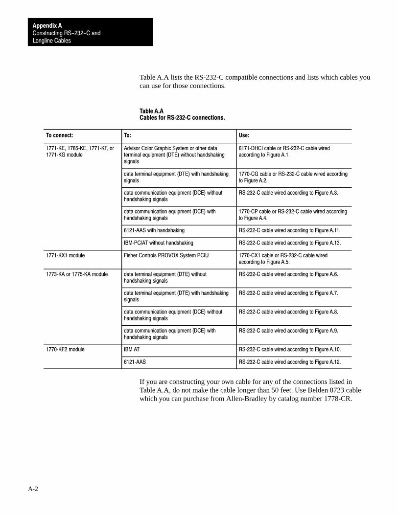
Constructing RS-232-C andLongline Cables
Appendix A
A-2
Table A.A lists the RS-232-C compatible connections and lists which cables youcan use for those connections.
Table A.ACables for RS�232�C connections.
To connect: To: Use:
1771�KE, 1785�KE, 1771�KF, or1771�KG module
Advisor Color Graphic System or other dataterminal equipment (DTE) without handshakingsignals
6171�DHCI cable or RS�232�C cable wiredaccording to Figure A.1.
data terminal equipment (DTE) with handshakingsignals
1770�CG cable or RS�232�C cable wired accordingto Figure A.2.
data communication equipment (DCE) withouthandshaking signals
RS�232�C cable wired according to Figure A.3.
data communication equipment (DCE) withhandshaking signals
1770�CP cable or RS�232�C cable wired accordingto Figure A.4.
6121�AAS with handshaking RS�232�C cable wired according to Figure A.11.
IBM�PC/AT without handshaking RS�232�C cable wired according to Figure A.13.
1771�KX1 module Fisher Controls PROVOX System PCIU 1770�CX1 cable or RS�232�C cable wiredaccording to Figure A.5.
1773�KA or 1775�KA module data terminal equipment (DTE) withouthandshaking signals
RS�232�C cable wired according to Figure A.6.
data terminal equipment (DTE) with handshakingsignals
RS�232�C cable wired according to Figure A.7.
data communication equipment (DCE) withouthandshaking signals
RS�232�C cable wired according to Figure A.8.
data communication equipment (DCE) withhandshaking signals
RS�232�C cable wired according to Figure A.9.
1770�KF2 module IBM AT RS�232�C cable wired according to Figure A.10.
6121�AAS RS�232�C cable wired according to Figure A.12.
If you are constructing your own cable for any of the connections listed inTable A.A, do not make the cable longer than 50 feet. Use Belden 8723 cablewhich you can purchase from Allen-Bradley by catalog number 1778-CR.
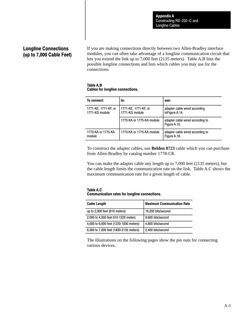
Constructing RS-232-C andLongline Cables
Appendix A
A-3
If you are making connections directly between two Allen-Bradley interfacemodules, you can often take advantage of a longline communication circuit thatlets you extend the link up to 7,000 feet (2135 meters). Table A.B lists thepossible longline connections and lists which cables you may use for theconnections.
Table A.BCables for longline connections.
To connect: to: use:
1771�KE, 1771�KF, or1771�KG module
1771�KE, 1771�KF, or1771�KG module
adapter cable wired accordingtoFigure A.14.
1773�KA or 1775�KA module adapter cable wired according toFigure A.15.
1773�KA or 1775�KAmodule
1773�KA or 1775�KA module adapter cable wired according toFigure A.16.
To construct the adapter cables, use Belden 8723 cable which you can purchasefrom Allen-Bradley by catalog number 1778-CR.
You can make the adapter cable any length up to 7,000 feet (2135 meters), butthe cable length limits the communication rate on the link. Table A.C shows themaximum communication rate for a given length of cable.
Table A.CCommunication rates for longline connections.
Cable Length Maximum Communication Rate
up to 2,000 feet (610 meters) 19,200 bits/second
2,000 to 4,000 feet 610�1220 meters 9,600 bits/second
4,000 to 6,000 feet (1220�1830 meters) 4,800 bits/second
6,000 to 7,000 feet (1830�2135 meters) 2,400 bits/second
The illustrations on the following pages show the pin outs for connectingvarious devices.
Longline Connections (up to 7,000 Cable Feet)

Constructing RS-232-C andLongline Cables
Appendix A
A-4
Figure A.1Connecting a module to an advisor system or other data terminal equipment(DTE) without handshaking.
2
3
4
5
6
7
8
11
13
1
3
2
4
5
6
7
8
20
1 AA
BB
BA
CA
CB
CD
AB
CF
CC
RS-232-CConnector of1771-KE,1771-KF, or1771-KG Module
RS-232-CConnector ofAdvisor Systemor Other DTE
RS-232-CPin Assignments:
AA Protective GroundAB Signal GroundBA Transmitted DataBB Received DataCA Request to SendCB Clear to SendCC Data Set ReadyCD Data Terminal ReadyCF Received Line Signal Detector
6171-DHC1 Cable (10 ft.)
15-pin MaleConnector
25-pin MaleConnector
NOTE: Depending on your DTE, you might have to jumper pins 4-5 and 6-8-20at the 25-pin connector.
12531
Important: Depending on your DTE, you might have to jumper pins 4-5 and6-8-20 at the 25-pin connector.
Figure A.2Connecting a module to data terminal equipment (DTE) with handshaking.
2
3
4
5
6
7
8
11
13
1
3
2
4
5
20
7
11
6
1 AA
BB
BA
CA
CB
CC
AB
CD
CF
RS-232-CConnector of1771-KE,1771-KF, or1771-KG Module
RS-232-CConnector of DTE
RS-232-CPin Assignments:
AA Protective GroundAB Signal GroundBA Transmitted DataBB Received DataCA Request to SendCB Clear to SendCC Data Set ReadyCD Data Terminal ReadyCF Received Line Signal Detector
1770-CG Cable (16.5 ft.)
15-pin MaleConnector
25-pin MaleConnector
12532
8

Constructing RS-232-C andLongline Cables
Appendix A
A-5
Figure A.3Connecting a module to data communication equipment (DCE) withouthandshaking.
2
3
4
5
6
7
8
11
13
1
2
3
4
5
6
7
8
20
1 AA
BA
BB
CA
CB
CD
AB
CF
CC
RS-232-CConnector of1771-KE,1771-KF, or1771-KG Module
RS-232-CConnector or DCE(E.g., a modem)
RS-232-CPin Assignments:
AA Protective GroundAB Signal GroundBA Transmitted DataBB Received DataCA Request to SendCB Clear to SendCC Data Set ReadyCD Data Terminal ReadyCF Received Line Signal Detector
15-pin MaleConnector
25-pin MaleConnector
12533
Figure A.4Connecting a module to data communication equipment (DCE) withhandshaking.
2
3
4
5
6
7
8
9
11
1
2
3
4
5
6
7
8
22
1 AA
BA
BB
CA
CB
CD
AB
CF
CE
RS-232-CConnector of1771-KE,1771-KF, or1771-KG Module
RS-232-CConnector or DCE(E.g., a modem)
RS-232-CPin Assignments:
AA Protective GroundAB Signal GroundBA Transmitted DataBB Received DataCA Request to SendCB Clear to SendCC Data Set ReadyCD Data Terminal ReadyCE Ring IndicatorCF Received Line Signal Detecto
15-pin MaleConnector
25-pin MaleConnector
12534
13
20
11
CC
1770-CP Cable (16.5 ft.)

Constructing RS-232-C andLongline Cables
Appendix A
A-6
Figure A.5Connecting a 1771�KX1 module to a PROVOX system.
2
3
4
5
6
7
8
11
13
1
3
2
4
5
20
7
6
8
1 AA
BB
BA
CA
CB
CC
AB
CD
CF
RS-232-CConnector of1771-KX1Module
RS-232-CConnector of PROVOXSystem PCIU)
RS-232-CPin Assignments:
AA Protective GroundAB Signal GroundBA Transmitted DataBB Received DataCA Request to SendCB Clear to SendCC Data Set ReadyCD Data Terminal ReadyCF Received Line Signal Detector
15-pin MaleConnector
25-pin FemaleConnector
12535
11
1770-CX1 Cable (16.5 ft.)
Figure A.6Connecting a module to data terminal equipment (DTE) without handshaking.
2
3
4
5
6
7
8
20
25
1
3
2
4
5
6
7
8
20
1 AA
BB
BA
CA
CB
CD
AB
CF
CC
RS-232-CConnector of1773-KA, or1775-KA,Module
RS-232-CConnector or DTE
RS-232-CPin Assignments:
AA Protective GroundAB Signal GroundBA Transmitted DataBB Received DataCA Request to SendCB Clear to SendCC Data Set ReadyCD Data Terminal ReadyCF Received Line Signal Detector
25-pin MaleConnector
25-pin MaleConnector
12536
Important: For the 1775-KA module, you do not have to ground pin 25 as longas switch 3 on the module is turned on (closed).
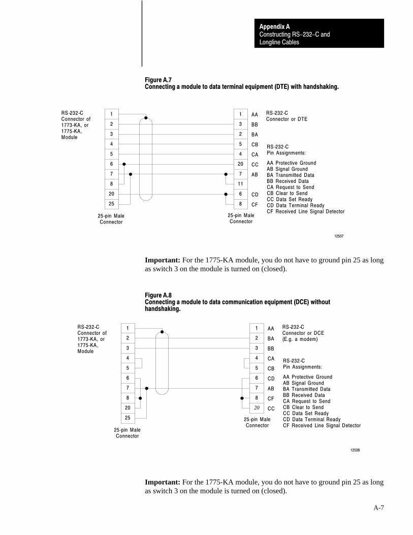
Constructing RS-232-C andLongline Cables
Appendix A
A-7
Figure A.7Connecting a module to data terminal equipment (DTE) with handshaking.
2
3
4
5
6
7
8
20
25
1
3
2
5
4
20
7
11
6
1 AA
BB
BA
CB
CA
CC
AB
CD
CF
RS-232-CConnector of1773-KA, or1775-KA,Module
RS-232-CConnector or DTE
RS-232-CPin Assignments:
AA Protective GroundAB Signal GroundBA Transmitted DataBB Received DataCA Request to SendCB Clear to SendCC Data Set ReadyCD Data Terminal ReadyCF Received Line Signal Detector
25-pin MaleConnector
25-pin MaleConnector
12537
8
Important: For the 1775-KA module, you do not have to ground pin 25 as longas switch 3 on the module is turned on (closed).
Figure A.8Connecting a module to data communication equipment (DCE) withouthandshaking.
2
3
4
5
6
7
8
20
25
1
2
3
4
5
6
7
8
20
1 AA
BA
BB
CA
CB
CD
AB
CF
CC
RS-232-CConnector of1773-KA, or1775-KA,Module
RS-232-CConnector or DCE(E.g. a modem)
RS-232-CPin Assignments:
AA Protective GroundAB Signal GroundBA Transmitted DataBB Received DataCA Request to SendCB Clear to SendCC Data Set ReadyCD Data Terminal ReadyCF Received Line Signal Detector
25-pin MaleConnector
25-pin MaleConnector
12538
Important: For the 1775-KA module, you do not have to ground pin 25 as longas switch 3 on the module is turned on (closed).

Constructing RS-232-C andLongline Cables
Appendix A
A-8
Figure A.9Connecting a module to data communication equipment (DCE) withhandshaking.
2
3
4
5
6
7
8
9
20
1
2
3
4
5
6
7
8
22
1 AA
BA
BB
CA
CB
CD
AB
CF
CE
RS-232-CConnector of1773-KA, or1775-KA,Module
RS-232-CConnector or DCE(E.g., a modem)
RS-232-CPin Assignments:
AA Protective GroundAB Signal GroundBA Transmitted DataBB Received DataCA Request to SendCB Clear to SendCC Data Set ReadyCD Data Terminal ReadyCE Ring IndicatorCF Received Line Signal Detector
25-pin MaleConnector
25-pin MaleConnector
12539
25
20
11
CC
Important: For the 1775-KA module, you do not have to ground pin 25 as longas switch 3 on the module is turned on (closed).
Figure A.10Connecting a 1770�KF2 to an IBM AT without handshaking.
2
7
3
4
5
6
8
20
2
5
3
1
4
6
7
8
25-pin Female1770-KF2
9-socketIBM-AT
18771
RXD
GND
TXD
DCD
DTR
DSR
RTS
CTS
RTS
CTS
DSR
DCD
DTR

Constructing RS-232-C andLongline Cables
Appendix A
A-9
Figure A.11Connecting a 1771�KG, �KE, �KF, or 1785�KE to a 6121�AAS with handshaking.
2
3
6
8
11
7
13
4
2
3
4
1
6
5
7
8
15-pin Male1771-KG, -KE, -KF, 1785-KE
9-pin Female6121-AAS
18772
5
Figure A.12Connecting a 1770�KF2 to a 6121�AAS with handshaking.
2
3
6
8
20
7
13
4
2
3
4
1
6
5
7
8
25-pin Female1770-KF2
9-pin Female6121-AAS
18773
5

Constructing RS-232-C andLongline Cables
Appendix A
A-10
Figure A.13Connecting a 1771�KF, �KG, �KE or 1785�KE to an IBM�PC/AT withouthandshaking.
1
2
7
3
13
4
5
6
8
11
1
4
6
2
5
3
7
8
D - sub 9 - pin(IBM - PC/AT)
14936
D - sub 15 - pin(1785-KE)
Figure A.14A Longline connection between 1771�KE, 1771�KF and 1771�KG modules.
2
14
3
13
4
5
6
8
11
1
3
13
2
4
5
1
6
8
11
14
15-pin MaleConnector
RS-232-CPORT Connectorof 1771-KE,1771-KF, or1771-KGModule
RS-232-CPORT Connectorof 1771-KE,1771-KF, or1771-KGModule
15-pin MaleConnector
Connect the shieldat one end only
User-supplied cable,Belden 8723, or Equivalent(7000 ft. max)
NOTE: User supplied male connectors
12540
Important: For cables longer than 50 feet, conductors 2 and 14, and 3 and 13must be twisted pairs.

Constructing RS-232-C andLongline Cables
Appendix A
A-11
Figure A.15A longline connection from a 1771�KE, 1771�KF, or 1771�KG module to a1773�KA or 1775�KA module.
2
14
3
13
4
5
6
8
11
1
3
25
2
4
5
1
6
8
20
7
15-pin MaleConnector
RS-232-CPORT Connectorof 1771-KE,1771-KF, or1771-KGModule
RS-232-CPORT Connectorof 1773-KAor 1775-KAModule
25-pin MaleConnector
Connect the shieldat one end only
User-supplied cable,Belden 8723, or Equivalent(7000 ft. max)
NOTE: User supplied male connectors
12542
Important: For cables longer than 50 feet, conductors 2 and 14, and 3 and 13must be twisted pairs.
Important: For a 1775-KA module, turn off (open) switch 3 on the module.

Constructing RS-232-C andLongline Cables
Appendix A
A-12
Figure A.16A longline connection between 1773�KA and 1775�KA modules.
2
7
3
25
4
5
6
8
20
1
3
25
2
4
5
1
6
8
20
7
RS-232-CCHANNELconnector of1773-KA or1775-KAModule
RS-232-CCHANNELconnector of1773-KA or1775-KAModule
Connect the shieldat one end only
12542
Important: For cables longer than 50 feet, conductors 2 and 7, and 3 and 25must be twisted pairs.
Important: For a 1775-KA module, turn off (open) switch 3 on the module.

C
Cabledata highway
construction of, using 1770-XGconnector kits, 3�17
determining length, 2�12dropline specifications, 2�3trunkline specifications, 2�3
data highway IIconstruction of, 6�1determining length, 5�8dropline specifications, 5�5ordering, 5�4trunkline specifications, 5�3
data highway plusconstruction of
using 1770-XG connectorkits, 3�17
using daisy chainconfiguration, 3�32
determining length, 2�12dropline specifications, 2�3trunkline specifications, 2�3
data highway-485construction of, 9�1determining length, 8�3trunkline specifications, 8�2
longline, construction of, A�3RS-232-C, construction of, A�1
Cable Systemdata highway. See data highwaydata highway II. See data highway IIdata highway plus. See data highway
plusdata highway-485. See data
highway-485
Communicationon data highway, 1�2on data highway plus, 1�5on data highway-485, 7�2
Components, data highway-485. See datahighway-485
Conductor descriptionscontrol and ac power, 2�14, 5�11, 8�5intra-enclosure, 2�15, 5�11, 8�5signal communication, 2�14, 5�11, 8�5
Conductorscategories, 2�14, 5�10, 8�4routing, 2�15, 5�12, 8�5
D
Data Highwaycommunication on, 1�2components of, 2�2construction of, 3�1
determining cable length, 2�12necessary tools, 2�12using 1770-XG connector kits, 3�17
devices used on, 1�2dropline, specifications of, 2�3overview of, 1�1planning, 2�1raceway layout considerations, 2�14station connector, 2�4trunkline, 2�3
Data Highway IIcomponents of, 5�1conductors
categories, 5�10routing, 5�12
construction of, 6�1determining cable length, 5�8necessary tools, 5�7
dropline, specifications of, 5�5overview of, 4�1planning, 5�1raceway layout considerations, 5�10taps, 5�5trunkline, 5�3
Data Highway Pluscommunication on, 1�5components of, 2�2conductors
categories, 2�14routing, 2�15
construction of, 3�1determining cable length, 2�12necessary tools, 2�12using 1770-XG connector kits, 3�17using daisy chain configuration, 3�32
devices used on, 1�4dropline, specifications of, 2�3overview of, 1�4planning, 2�1raceway layout considerations, 2�14station connector, 2�4trunkline, 2�3
Data Highway-485communication on, 7�2
Index

IndexI–2
components of, 8�2conductors
categories, 8�4routing, 8�5
construction of, 9�1determining cable length, 8�3necessary tools, 8�3
link coupler, 8�3overview of, 7�1planning, 8�1raceway layout considerations, 8�4trunkline, 8�2, 9�1
DH. See data highway
DH II. See data highway II
DH+. See data highway plus
DH-485. See data highway-485
Droplinedata highway
construction of, 3�2specifications of, 2�3testing of, 3�7
data highway II, specifications of, 5�5data highway plus
construction of, 3�2specifications of, 2�3, 5�5testing of, 3�7
E
Electrical Testingof data highway dropline, 3�7of data highway plus dropline, 3�7
G
Glossary. See terms
I
I/O module placement, considerations, 2�14, 5�10, 8�4
I/O raceway layoutconductor categories, 2�14, 5�10, 8�4routing categories, 2�15, 5�12, 8�5
Installingdropline
data highway, 3�2data highway plus, 3�2
link coupler, 9�1station connector
data highway, 3�9, 3�17data highway plus, 3�9, 3�17
terminatorsdata highway, 3�14, 3�30
data highway plus, 3�14, 3�30data highway-485, 9�5
trunklinedata highway, 3�17, 3�32data highway plus, 3�17, 3�32data highway-485, 9�1
L
Link Coupler, 8�3choosing number of, 8�4installation of, 9�1
Longline Cable, construction of, A�3
M
Manual, organization of, i
N
Nodeadding
data highway, 3�33data highway plus, 3�33
removingdata highway, 3�34data highway plus, 3�34
O
Ordering Informationcable, data highway II, 5�4station connector, 1770-XG, 2�8tap, 5�6terminators, 5�7tools, 5�7
Organization, of manual, i
P
Planning, installationdata highway, 2�1data highway II, 5�1data highway plus, 2�1data highway-485, 8�1
Precautionary Notes, ii
Products. See related products
Publications. See related publications
R
Reconfigure Network, 3�33

Index I–3
Related Products, iii
Related Publications, iv
Routing cables, categories, 2�16, 5�13, 8�6
RS-232-C Cable, construction of, A�1
S
Specificationsdata highway
dropline, 2�3station connector, 2�5, 2�6terminators, 2�11trunkline, 2�3
data highway IIdropline, 5�5tap, 5�5terminators, 5�6trunkline, 5�3
data highway plusdropline, 2�3station connector, 2�5, 2�6terminators, 2�11trunkline, 2�3
data highway-485link coupler, 8�3terminators, 9�5trunkline, 8�2
Station Connector1770-SC
components of, 2�5installation of, 3�9terminating, 3�14
1770-XGcomponents of, 2�6installation of, 3�17ordering, 2�8terminators, 2�11, 3�30testing of, 3�27
adding, 3�33choosing number of
data highway, 2�13
data highway plus, 2�13choosing type of
data highway, 2�4data highway plus, 2�4
removing, 3�34
T
Tapchoosing number of, 5�10components of, 5�5ordering, 5�6
Terminatorfor data highway, 2�11for data highway plus, 2�11
Terminatorsfor data highway, 3�14, 3�30for data highway II, 5�6
ordering, 5�7for data highway plus, 3�14, 3�30for data highway-485, 9�5
Terms, definition of, ii
Tools, for constructing networkdata highway, 2�12data highway II, 5�7
ordering, 5�7data highway plus, 2�12data highway-485, 8�3
Trunklineinstallation of, data highway-485, 9�1specifications of
data highway, 2�3data highway II, 5�3data highway plus, 2�3data highway-485, 8�2
W
Wires and cablescategories, 2�14, 5�10, 8�4routing, 2�15, 5�12, 8�5

PLC is a registered trademark of Allen-Bradley Company, Inc.
The following are trademarks of Allen-Bradley Company, Inc.: Pyramid Integrator, CVIM, SLC, SMC, RediPANEL, PHOTOSWITCH, Advisor, VIM, EXPERT, Multiprogramming, Pro-Spec.
DataMyte, FAN, FANLINK, and DataTruck are registered trademarks of DataMyte Corporation.
DEC, MicroVAX, VAX, VAXcluster, VMS, DECnet, PDP, and RSX are trademarks of Digital Equipment Corporation.
IBM is a registered trademark of International Business Machines Corporation.
Ethernet is a trademark of Intel Corporation, Xerox Corporation, and Digital Equipment Corporation.
NetWare is a trademark of Novell Incorporated.
3COM is a trademark of 3COM Corporation.
UNIX is a trademark of AT&T.
ChronOS, LNQ and RealRAM are trademarks of Dynapro Systems, Inc.
GRAFIX is a registered trademark of Dynapro Systems, Inc.
EXACT is a trademark of the Foxboro Company.
PROVOX is a registered trademark of Fisher Controls.
With major offices worldwide.
Algeria • Argentina • Australia • Austria • Bahrain • Belgium • Brazil • Bulgaria • Canada • Chile • China, PRC • Colombia • Costa Rica • Croatia • Cyprus • Czech
Republic • Denmark • Ecuador • Egypt • El Salvador • Finland • France • Germany • Greece • Guatemala • Honduras • Hong Kong • Hungary • Iceland • India •Indonesia • Israel • Italy • Jamaica • Japan • Jordan • Korea • Kuwait • Lebanon • Malaysia • Mexico • New Zealand • Norway • Oman • Pakistan • Peru • Philippines
• Poland • Portugal • Puerto Rico • Qatar • Romania • Russia-CIS • Saudi Arabia • Singapore • Slovakia • Slovenia • South Africa, Republic • Spain • Switzerland •Taiwan • Thailand • The Netherlands • Turkey • United Arab Emirates • United Kingdom • United States • Uruguay • Venezuela • Yugoslavia
World Headquarters, Allen�Bradley, 1201 South Second Street, Milwaukee, WI 53204 USA, Tel: (1) 414 382�2000 Fax: (1) 414 382�4444
Allen�Bradley has been helping its customers improve productivity and quality for 90 years.
A�B designs, manufactures and supports a broad range of control and automation products
worldwide. They include logic processors, power and motion control devices, man�machine
interfaces and sensors. Allen�Bradley is a subsidiary of Rockwell International, one of the
world's leading technology companies.
Publication 1770�6.2.2 - April 1994Supersedes Publication 1770�6.2.2 - July 1991
P/N 404635202Copyright 1994 Allen�Bradley Company, Inc. Printed in USA


![[XLS]On Highway Motorcycle 2015 Certification Data · Web viewTitle On Highway Motorcycle 2015 Certification Data Subject This is the On Highway Motorcycle Certification and Greenhouse](https://static.fdocuments.net/doc/165x107/5b04384b7f8b9a89208d4308/xlson-highway-motorcycle-2015-certification-data-viewtitle-on-highway-motorcycle.jpg)