1756 ControlLogix I/O Specifications Technical Data1756 ControlLogix I/O Specifications 1756 Series...
248
Technical Data 1756 ControlLogix I/O Specifications 1756 Series Catalog Numbers The ControlLogix® architecture provides a wide range of input and output modules to span many applications, from high-speed digital to process control. The ControlLogix architecture uses Producer-Consumer technology, which allows input information and output status to be shared among multiple ControlLogix controllers. Each ControlLogix I/O module mounts in a ControlLogix chassis and requires either a removable terminal block (RTB) or a 1492 interface module (IFM) to connect all field-side wiring. RTBs and IFMs are not included with the I/O modules. They must be ordered separately. Topic Page Available 1756 I/O Modules 2 ControlLogix I/O Accessories 244 Additional Resources 246
Transcript of 1756 ControlLogix I/O Specifications Technical Data1756 ControlLogix I/O Specifications 1756 Series...

Technical Data
1756 ControlLogix I/O Specifications1756 Series Catalog Numbers
The ControlLogix® architecture provides a wide range of input and output modules to span many applications, from high-speed digital to process control. The ControlLogix architecture uses Producer-Consumer technology, which allows input information and output status to be shared among multiple ControlLogix controllers.
Each ControlLogix I/O module mounts in a ControlLogix chassis and requires either a removable terminal block (RTB) or a 1492 interface module (IFM) to connect all field-side wiring. RTBs and IFMs are not included with the I/O modules. They must be ordered separately.
Topic Page
Available 1756 I/O Modules 2
ControlLogix I/O Accessories 244
Additional Resources 246

1756 ControlLogix I/O Specifications
Available 1756 I/O Modules
You can select these types of digital I/O modules.
Digital I/O Type Description
Diagnostic These modules provide diagnostic features to the point level. These modules have a D at the end of the catalog number.
Electronic fusing These modules have internal electronic fusing to prevent too much current from flowing through the module. These modules have an E at the end of the catalog number.
Individually isolated These modules have individually isolated inputs or outputs. These modules have an I at the end of the catalog number.
I/O Type Cat. No. Page Cat. No. Page
AC digital 1756-IA8D1756-IA161756-IA16I1756-IA321756-IM16I1756-IN16
369128588
1756-LSC8XIB8I1756-OA8D1756-OA8E1756-OA161756-OA16I1756-ON8
234128131134138207
DC digital 1756-IB161756-IB16D1756-IB16I1756-IB16IF1756-IB16IOSE1756-IB321756-IC161756-IG161756-IH16I1756-IH16ISOE1756-IV161756-IV321756-OB81756-OB8EI
15182226303336767982119122141144
1756-OB8I1756-OB16D1756-OB16E1756-OB16I1756-OB16IEF1756-OB16IEFS1756-OB16IS1756-OB321756-OC81756-OG161756-OH8I1756-OV16E1756-OV32E
147150153157160163166169172201204211215
Contact 1756-OW16I1756-OX8I
219222
Analog 1756-IF6CIS1756-IF6I1756-IF81756-IF8I1756-IF161756-IF4FXOF2F1756-IR6I1756-IRT8I1756-IR121756-IT6I1756-IT6I21756-IT16
4347526068399196102106110114
1756-OF41756-OF6CI1756-OF6VI1756-OF81756-OF8I
175179183186193
HART interface 1756-IF8H1756-IF8IH1756-IF16H
576473
1756-OF8H1756-OF8IH
190197
Specialty 1756-CFM1756-HSC
225230
1756-LSC8XIB8I1756-PLS
234238
2 Rockwell Automation Publication 1756-TD002I-EN-E - June 2015
1756 ControlLogix I/O Specifications
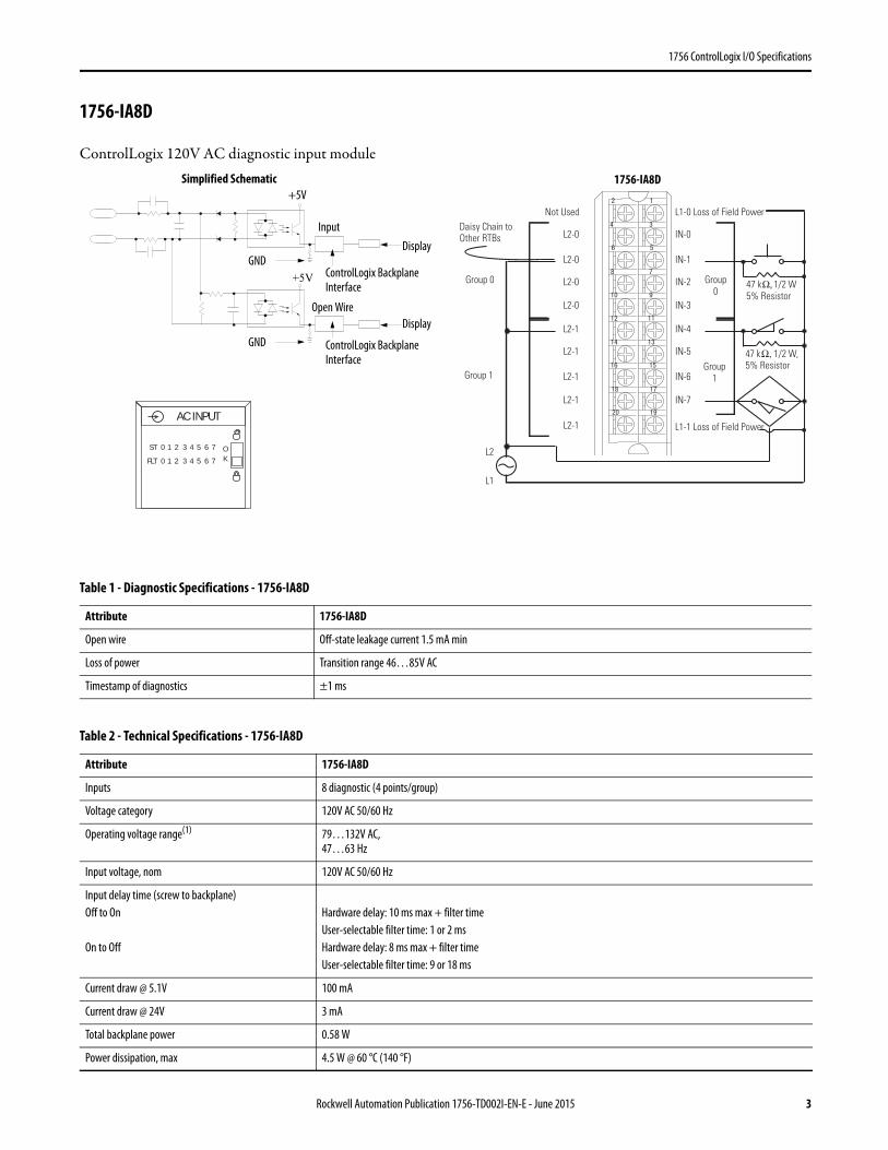
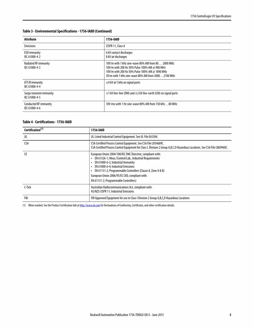
1756-IA8D
ControlLogix 120V AC diagnostic input module
Table 1 - Diagnostic Specifications - 1756-IA8D
Attribute 1756-IA8D
Open wire Off-state leakage current 1.5 mA min
Loss of power Transition range 46…85V AC
Timestamp of diagnostics ±1 ms
Table 2 - Technical Specifications - 1756-IA8D
Attribute 1756-IA8D
Inputs 8 diagnostic (4 points/group)
Voltage category 120V AC 50/60 Hz
Operating voltage range(1) 79…132V AC,47…63 Hz
Input voltage, nom 120V AC 50/60 Hz
Input delay time (screw to backplane)Off to On
On to Off
Hardware delay: 10 ms max + filter timeUser-selectable filter time: 1 or 2 msHardware delay: 8 ms max + filter timeUser-selectable filter time: 9 or 18 ms
Current draw @ 5.1V 100 mA
Current draw @ 24V 3 mA
Total backplane power 0.58 W
Power dissipation, max 4.5 W @ 60 °C (140 °F)
+5V
12
34
56
78
910
1112
1314
1516
1718
1920
47 kΩ, 1/2 W, 5% Resistor
47 kΩ, 1/2 W5% Resistor
Not Used
L2-0
L2-0
L2-0
L2-0
L2-1
L2-1
L2-1
L2-1
L2-1
L1-0 Loss of Field Power
IN-0
IN-1
IN-2
IN-3
IN-4
IN-5
IN-6
IN-7
L1-1 Loss of Field Power
Daisy Chain to Other RTBs
Group 0
Group 0
Group 1Group 1
L2
L1
ControlLogix Backplane Interface
ControlLogix Backplane Interface
Display
Simplified Schematic
Input
DisplayOpen Wire
GND
GND
+5V
AC INPUT
ST
FLT
0 1 2 3 4 5 6 7
0 1 2 3 4 5 6 7OK
1756-IA8D
Rockwell Automation Publication 1756-TD002I-EN-E - June 2015 3

1756 ControlLogix I/O Specifications
Thermal dissipation 15.35 BTU/hr
Off-state voltage, max 20V
Off-state current, max 2.5 mA
On-state current, min 5 mA @ 74V AC
On-state current, max 16 mA @ 132V AC
Inrush current, max 250 mA
Input impedance, max 8.25 kΩ @ 132V AC, 60 Hz
Cyclic update time 200 μs…750 ms
Change of state Software configurable
Timestamp of inputs ±200 μs
Isolation voltage 125V (continuous), basic insulation type, inputs-to-backplane, and input group-to-groupNo isolation between individual group inputsRoutine tested @ 1200V AC for 2 s
Module keying Electronic, software configurable
Removable terminal block housing 1756-TBNH1756-TBSH
RTB keying User-defined mechanical
Slot width 1
Wire category 1(2)
North American temperature code T4A
Enclosure type None (open-style)
(1) UL certification for 120V 50/60 Hz nominal. Rockwell Automation specified to 74…132V, 47…63 Hz. (2) Use this conductor category information for planning conductor routing as described in the system-level installation manual. See the Industrial Automation Wiring and Grounding Guidelines,
publication 1770-4.1.
Table 3 - Environmental Specifications - 1756-IA8D
Attribute 1756-IA8D
Temperature, operatingIEC 60068-2-1 (Test Ad, Operating Cold),IEC 60068-2-2 (Test Bd, Operating Dry Heat),IEC 60068-2-14 (Test Nb, Operating Thermal Shock)
0…60 °C (32…140 °F)
Temperature, surrounding air, max 60 °C (140 °F)
Temperature, nonoperatingIEC 60068-2-1 (Test Ab, Unpackaged Nonoperating Cold),IEC 60068-2-2 (Test Bb, Unpackaged Nonoperating Dry Heat),IEC 60068-2-14 (Test Na, Unpackaged Nonoperating Thermal Shock)
-40…85 °C (-40…185 °F)
Relative humidityIEC 60068-2-30 (Test Db, Unpackaged Damp Heat)
5…95% noncondensing
VibrationIEC 60068-2-6 (Test Fc, Operating)
2 g @ 10…500 Hz
Shock, operatingIEC 60068-2-27 (Test Ea, Unpackaged Shock)
30 g
Shock, nonoperatingIEC 60068-2-27 (Test Ea, Unpackaged Shock)
50 g
Table 2 - Technical Specifications - 1756-IA8D (Continued)
Attribute 1756-IA8D
4 Rockwell Automation Publication 1756-TD002I-EN-E - June 2015
1756 ControlLogix I/O Specifications
Emissions CISPR 11, Class A
ESD immunityIEC 61000-4-2
6 kV contact discharges8 kV air discharges
Radiated RF immunityIEC 61000-4-3
10V/m with 1 kHz sine-wave 80% AM from 80… 2000 MHz10V/m with 200 Hz 50% Pulse 100% AM @ 900 MHz10V/m with 200 Hz 50% Pulse 100% AM @ 1890 MHz3V/m with 1 kHz sine-wave 80% AM from 2000…2700 MHz
EFT/B immunityIEC 61000-4-4
±4 kV at 5 kHz on signal ports
Surge transient immunityIEC 61000-4-5
±1 kV line-line (DM) and ±2 kV line-earth (CM) on signal ports
Conducted RF immunityIEC 61000-4-6
10V rms with 1 Hz sine-wave 80% AM from 150 kHz…80 MHz
Table 4 - Certifications - 1756-IA8D
Certification(1)
(1) When marked. See the Product Certification link at http://www.ab.com for Declarations of Conformity, Certificates, and other certification details.
1756-IA8D
UL UL Listed Industrial Control Equipment. See UL File E65584.
CSA CSA Certified Process Control Equipment. See CSA File LR54689C.CSA Certified Process Control Equipment for Class I, Division 2 Group A,B,C,D Hazardous Locations. See CSA File LR69960C.
CE European Union 2004/108/IEC EMC Directive, compliant with:• EN 61326-1; Meas./Control/Lab., Industrial Requirements• EN 61000-6-2; Industrial Immunity• EN 61000-6-4; Industrial Emissions• EN 61131-2; Programmable Controllers (Clause 8, Zone A & B)European Union 2006/95/EC LVD, compliant with:EN 61131-2; Programmable Controllers)
C-Tick Australian Radiocommunications Act, compliant with:AS/NZS CISPR 11; Industrial Emissions
FM FM Approved Equipment for use in Class I Division 2 Group A,B,C,D Hazardous Locations
Table 3 - Environmental Specifications - 1756-IA8D (Continued)
Attribute 1756-IA8D
Rockwell Automation Publication 1756-TD002I-EN-E - June 2015 5
1756 ControlLogix I/O Specifications
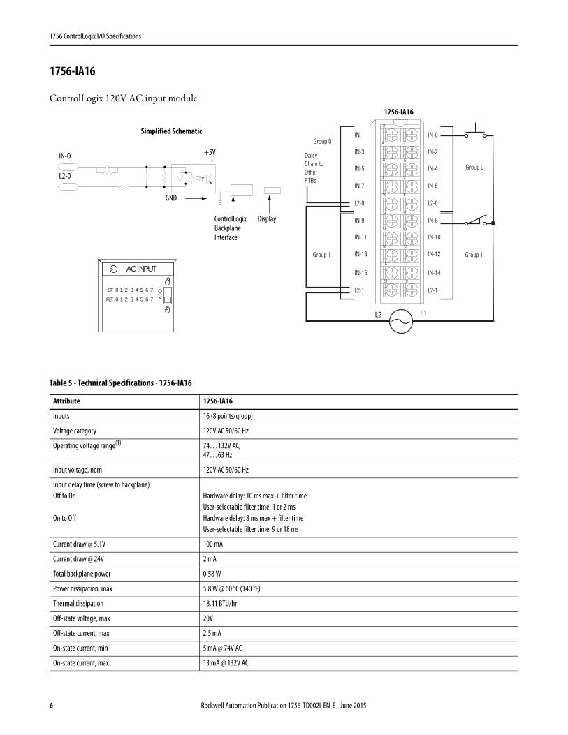
1756-IA16
ControlLogix 120V AC input module
Table 5 - Technical Specifications - 1756-IA16
Attribute 1756-IA16
Inputs 16 (8 points/group)
Voltage category 120V AC 50/60 Hz
Operating voltage range(1) 74…132V AC,47…63 Hz
Input voltage, nom 120V AC 50/60 Hz
Input delay time (screw to backplane)Off to On
On to Off
Hardware delay: 10 ms max + filter timeUser-selectable filter time: 1 or 2 msHardware delay: 8 ms max + filter timeUser-selectable filter time: 9 or 18 ms
Current draw @ 5.1V 100 mA
Current draw @ 24V 2 mA
Total backplane power 0.58 W
Power dissipation, max 5.8 W @ 60 °C (140 °F)
Thermal dissipation 18.41 BTU/hr
Off-state voltage, max 20V
Off-state current, max 2.5 mA
On-state current, min 5 mA @ 74V AC
On-state current, max 13 mA @ 132V AC
12
34
56
78
910
1112
1314
1516
1718
1920
L2 L1
Daisy Chain to OtherRTBs
Group 0
Group 0
Group 1Group 1
IN-1
IN-3
IN-5
IN-7
L2-0
IN-9
IN-11
IN-13
IN-15
L2-1
IN-0
IN-2
IN-4
IN-6
L2-0
IN-8
IN-10
IN-12
IN-14
L2-1
Simplified Schematic
ControlLogix Backplane Interface
Display
+5V
L2-0
IN-O
GND
AC INPUT
ST
FLT
0 1 2 3 4 5 6 7
0 1 2 3 4 5 6 7OK
1756-IA16
6 Rockwell Automation Publication 1756-TD002I-EN-E - June 2015

1756 ControlLogix I/O Specifications
Inrush current, max 250 mA peak (decaying to <37% in 22 ms, without activation)
Input impedance, max 10.15 kΩ @ 132V AC, 60 Hz
Cyclic update time 200 μs…750 ms
Change of state Software configurable
Timestamp of inputs ±200 μs
Isolation voltage 125V (continuous), basic insulation type, inputs-to-backplane, and input group-to-groupNo isolation between individual group inputsRoutine tested @ 1400V AC for 2 s
Module keying Electronic, software configurable
Removable terminal block housing 1756-TBNH1756-TBSH
RTB keying User-defined mechanical
Slot width 1
Wire category 1(2)
North American temperature code T4
Enclosure type None (open-style)
(1) UL certification for 120V 50/60 Hz nominal. Rockwell Automation specified to 74…132V, 47…63 Hz. (2) Use this conductor category information for planning conductor routing as described in the system-level installation manual. See the Industrial Automation Wiring and Grounding Guidelines,
publication 1770-4.1.
Table 6 - Environmental Specifications - 1756-IA16
Attribute 1756-IA16
Temperature, operatingIEC 60068-2-1 (Test Ad, Operating Cold),IEC 60068-2-2 (Test Bd, Operating Dry Heat),IEC 60068-2-14 (Test Nb, Operating Thermal Shock)
0…60 °C (32…140 °F)
Temperature, surrounding air, max 60 °C (140 °F)
Temperature, nonoperatingIEC 60068-2-1 (Test Ab, Unpackaged Nonoperating Cold),IEC 60068-2-2 (Test Bb, Unpackaged Nonoperating Dry Heat),IEC 60068-2-14 (Test Na, Unpackaged Nonoperating Thermal Shock)
-40…85 °C (-40…185 °F)
Relative humidityIEC 60068-2-30 (Test Db, Unpackaged Damp Heat)
5…95% noncondensing
VibrationIEC 60068-2-6 (Test Fc, Operating)
2 g @ 10…500 Hz
Shock, operatingIEC 60068-2-27 (Test Ea, Unpackaged Shock)
30 g
Shock, nonoperatingIEC 60068-2-27 (Test Ea, Unpackaged Shock)
50 g
Emissions CISPR 11, Class A
ESD immunityIEC 61000-4-2
6 kV contact discharges8 kV air discharges
Radiated RF immunityIEC 61000-4-3
10V/m with 1 kHz sine-wave 80% AM from 80… 2000 MHz10V/m with 200 Hz 50% Pulse 100% AM @ 900 MHz10V/m with 200 Hz 50% Pulse 100% AM @ 1890 MHz3V/m with 1 kHz sine-wave 80% AM from 2000…2700 MHz
Table 5 - Technical Specifications - 1756-IA16 (Continued)
Attribute 1756-IA16
Rockwell Automation Publication 1756-TD002I-EN-E - June 2015 7
1756 ControlLogix I/O Specifications
EFT/B immunityIEC 61000-4-4
±4 kV at 5 kHz on signal ports
Surge transient immunityIEC 61000-4-5
±1 kV line-line (DM) and ±2 kV line-earth (CM) on signal ports
Conducted RF immunityIEC 61000-4-6
10V rms with 1 kHz sine-wave 80% AM from 150 kHz…80 MHz
Oscillatory surge withstandIEEE C37.90.1
3 kV
Table 7 - Certifications - 1756-IA16
Certification(1)
(1) When marked. See the Product Certification link at http://www.ab.com for Declarations of Conformity, Certificates, and other certification details.
1756-IA16
UL UL Listed Industrial Control Equipment. See UL File E65584.
CSA CSA Certified Process Control Equipment. See CSA File LR54689C.CSA Certified Process Control Equipment for Class I, Division 2 Group A,B,C,D Hazardous Locations. See CSA File LR69960C.
CE European Union 2004/108/IEC EMC Directive, compliant with:• EN 61326-1; Meas./Control/Lab., Industrial Requirements• EN 61000-6-2; Industrial Immunity• EN 61000-6-4; Industrial Emissions• EN 61131-2; Programmable Controllers (Clause 8, Zone A & B)European Union 2006/95/EC LVD, compliant with:EN 61131-2; Programmable Controllers
C-Tick Australian Radiocommunications Act, compliant with:AS/NZS CISPR 11; Industrial Emissions
FM FM Approved Equipment for use in Class I Division 2 Group A,B,C,D Hazardous Locations
KC Korean Registration of Broadcasting and Communications Equipment, compliant with:Article 58-2 of Radio Waves Act, Clause 3
Table 6 - Environmental Specifications - 1756-IA16 (Continued)
Attribute 1756-IA16
8 Rockwell Automation Publication 1756-TD002I-EN-E - June 2015
1756 ControlLogix I/O Specifications
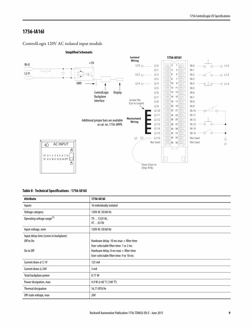
1756-IA16I
ControlLogix 120V AC isolated input module
Table 8 - Technical Specifications - 1756-IA16I
Attribute 1756-IA16I
Inputs 16 individually isolated
Voltage category 120V AC 50/60 Hz
Operating voltage range(1) 79…132V AC,47…63 Hz
Input voltage, nom 120V AC 50/60 Hz
Input delay time (screw to backplane)Off to On
On to Off
Hardware delay: 10 ms max + filter timeUser-selectable filter time: 1 or 2 msHardware delay: 8 ms max + filter timeUser-selectable filter time: 9 or 18 ms
Current draw @ 5.1V 125 mA
Current draw @ 24V 3 mA
Total backplane power 0.71 W
Power dissipation, max 4.9 W @ 60 °C (140 °F)
Thermal dissipation 16.71 BTU/hr
Off-state voltage, max 20V
Nonisolated Wiring
IsolatedWiring
12
34
56
78
910
1112
1314
1516
1718
1920
2122
2324
2526
2728
2930
3132
3334
3536
Daisy Chain to Other RTBs
L2-0 L2-0L2-1
L2-2
L2-3
L2-8
L2-4
L2-5
L2-6
L2-7
Not Used
L2-9
L2-10
L2-11
L2-12
L2-13L2-14
L2-15
L2-15
IN-0IN-1
IN-2
IN-3
IN-8
IN-4
IN-5
IN-6
IN-7
Not Used
IN-9
IN-10
IN-11
IN-12
IN-13IN-14
IN-15
Not Used
L2-2
L2-4
L2
L1
L1-0
L1-2
L1-4
Jumper Bar (Cut to Length)
ControlLogix Backplane Interface
Display
Simplified Schematic
+5V
L2-0
IN-O
GND
Additional jumper bars are availableas cat. no. 1756-JMPR.
ST 0 1 2 3 4 5 6 7
ST 8 9 10 11 12 13 14 15
OK
AC INPUT
1756-IA161
Rockwell Automation Publication 1756-TD002I-EN-E - June 2015 9

1756 ControlLogix I/O Specifications
Off-state current, max 2.5 mA
On-state current, min 5 mA @ 79V AC, 47…63 Hz
On-state current, max 15 mA @ 132V AC, 47…63 Hz
Inrush current, max 250 mA
Input impedance, max 8.8 kΩ @ 132V AC, 60 Hz
Cyclic update time 200 μs…750 ms
Change of state Software configurable
Timestamp of inputs ±200 μs
Isolation voltage 125V (continuous), basic insulation type, inputs-to-backplane, and input-to-inputRoutine tested @ 1200V AC for 2 s
Module keying Electronic, software configurable
Removable terminal block housing 1756-TBCH1756-TBS6H
RTB keying User-defined mechanical
Slot width 1
Wire category 1(2)
North American temperature code T4A
Enclosure type None (open-style)
(1) UL certification for 120V 50/60 Hz nominal. Rockwell Automation specified to 74…132V, 47…63 Hz. (2) Use this conductor category information for planning conductor routing as described in the system-level installation manual. See the Industrial Automation Wiring and Grounding Guidelines,
publication 1770-4.1.
Table 9 - Environmental Specifications - 1756-IA16I
Attribute 1756-IA16I
Temperature, operatingIEC 60068-2-1 (Test Ad, Operating Cold),IEC 60068-2-2 (Test Bd, Operating Dry Heat),IEC 60068-2-14 (Test Nb, Operating Thermal Shock)
0…60 °C (32…140 °F)
Temperature, surrounding air, max 60 °C (140 °F)
Temperature, nonoperatingIEC 60068-2-1 (Test Ab, Unpackaged Nonoperating Cold),IEC 60068-2-2 (Test Bb, Unpackaged Nonoperating Dry Heat),IEC 60068-2-14 (Test Na, Unpackaged Nonoperating Thermal Shock)
-40…85 °C (-40…185 °F)
Relative humidityIEC 60068-2-30 (Test Db, Unpackaged Damp Heat)
5…95% noncondensing
VibrationIEC 60068-2-6 (Test Fc, Operating)
2 g @ 10…500 Hz
Shock, operatingIEC 60068-2-27 (Test Ea, Unpackaged Shock)
30 g
Shock, nonoperatingIEC 60068-2-27 (Test Ea, Unpackaged Shock)
50 g
Emissions CISPR 11, Class A
ESD immunityIEC 61000-4-2
6 kV contact discharges8 kV air discharges
Table 8 - Technical Specifications - 1756-IA16I (Continued)
Attribute 1756-IA16I
10 Rockwell Automation Publication 1756-TD002I-EN-E - June 2015
1756 ControlLogix I/O Specifications
,
Radiated RF immunityIEC 61000-4-3
10V/m with 1 kHz sine-wave 80% AM from 80… 2000 MHz10V/m with 200 Hz 50% Pulse 100% AM @ 900 MHz10V/m with 200 Hz 50% Pulse 100% AM @ 1890 MHz3V/m with 1 kHz sine-wave 80% AM from 2000…2700 MHz
EFT/B immunityIEC 61000-4-4
±4 kV at 5 kHz on signal ports
Surge transient immunityIEC 61000-4-5
±1 kV line-line (DM) and ±2 kV line-earth (CM) on signal ports
Conducted RF immunityIEC 61000-4-6
10V rms with 1 kHz sine-wave 80% AM from 150 kHz…80 MHz
Oscillatory surge withstandIEEE C37.90.1
3 kV
Table 10 - Certifications - 1756-IA16I
Certification(1)
(1) When marked. See the Product Certification link at http://www.ab.com for Declarations of Conformity, Certificates, and other certification details.
1756-IA16I
UL UL Listed Industrial Control Equipment. See UL File E65584.
CSA CSA Certified Process Control Equipment. See CSA File LR54689C.CSA Certified Process Control Equipment for Class I, Division 2 Group A,B,C,D Hazardous Locations. See CSA File LR69960C.
CE European Union 2004/108/IEC EMC Directive, compliant with:• EN 61326-1; Meas./Control/Lab., Industrial Requirements• EN 61000-6-2; Industrial Immunity• EN 61000-6-4; Industrial Emissions• EN 61131-2; Programmable Controllers (Clause 8, Zone A & B)European Union 2006/95/EC LVD, compliant with:EN 61131-2; Programmable Controllers
C-Tick Australian Radiocommunications Act, compliant with:AS/NZS CISPR 11; Industrial Emissions
FM FM Approved Equipment for use in Class I Division 2 Group A,B,C,D Hazardous Locations
KC Korean Registration of Broadcasting and Communications Equipment, compliant with:Article 58-2 of Radio Waves Act, Clause 3
Table 9 - Environmental Specifications - 1756-IA16I (Continued)
Attribute 1756-IA16I
Rockwell Automation Publication 1756-TD002I-EN-E - June 2015 11
1756 ControlLogix I/O Specifications
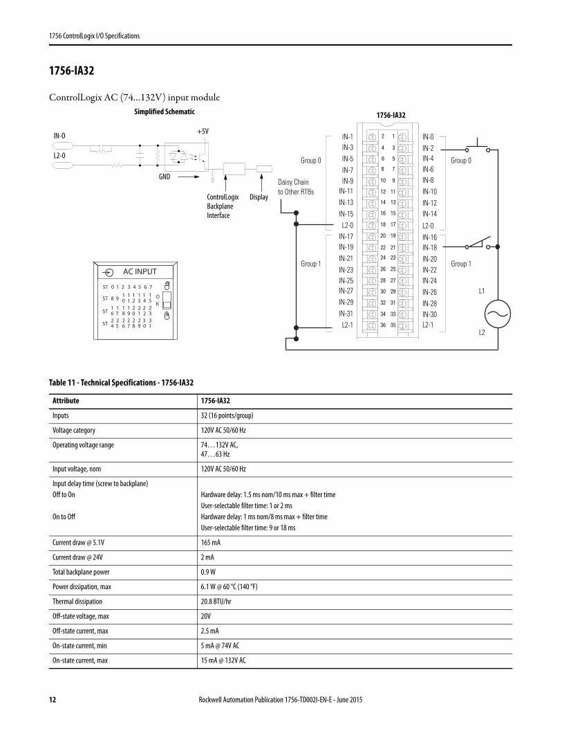
1756-IA32
ControlLogix AC (74…132V) input module
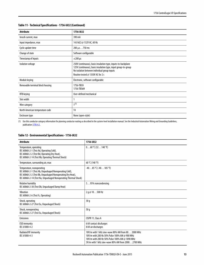
Table 11 - Technical Specifications - 1756-IA32
Attribute 1756-IA32
Inputs 32 (16 points/group)
Voltage category 120V AC 50/60 Hz
Operating voltage range 74…132V AC,47…63 Hz
Input voltage, nom 120V AC 50/60 Hz
Input delay time (screw to backplane)Off to On
On to Off
Hardware delay: 1.5 ms nom/10 ms max + filter timeUser-selectable filter time: 1 or 2 msHardware delay: 1 ms nom/8 ms max + filter timeUser-selectable filter time: 9 or 18 ms
Current draw @ 5.1V 165 mA
Current draw @ 24V 2 mA
Total backplane power 0.9 W
Power dissipation, max 6.1 W @ 60 °C (140 °F)
Thermal dissipation 20.8 BTU/hr
Off-state voltage, max 20V
Off-state current, max 2.5 mA
On-state current, min 5 mA @ 74V AC
On-state current, max 15 mA @ 132V AC
12
34
56
78
910
1112
1314
1516
1718
1920
2122
2324
2526
2728
2930
3132
3334
3536
IN-0IN-2IN-4IN-6IN-8IN-10IN-12IN-14
IN-16IN-18IN-20IN-22IN-24IN-26IN-28IN-30L2-1
L2-0
IN-1IN-3IN-5IN-7IN-9
IN-11IN-13IN-15L2-0
IN-17IN-19IN-21IN-23IN-25IN-27IN-29IN-31L2-1
L1
L2
Daisy Chain to Other RTBs
1 puorG1 puorG
0 puorG0 puorG
Simplified Schematic
ControlLogix Backplane Interface
Display
+5V
L2-0
IN-O
GND
AC INPUT
OK
ST 0 1 2 3 4 5 6 7
ST 8 910 21 3 4 5
1 1 1 11
ST 6 718 09 1 2 3
1 2 2 221 1
ST 4 526 87 9 0 1
2 2 2 332 2
1756-IA32
12 Rockwell Automation Publication 1756-TD002I-EN-E - June 2015
1756 ControlLogix I/O Specifications
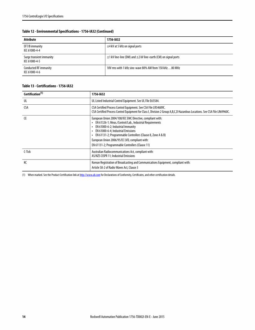
Inrush current, max 390 mA
Input impedance, max 14.0 kΩ @ 132V AC, 60 Hz
Cyclic update time 200 μs…750 ms
Change of state Software configurable
Timestamp of inputs ±200 μs
Isolation voltage 250V (continuous), basic insulation type, inputs-to-backplane125V (continuous), basic insulation type, input group-to-groupNo isolation between individual group inputsRoutine tested @ 1350V AC for 2 s
Module keying Electronic, software configurable
Removable terminal block housing 1756-TBCH1756-TBS6H
RTB keying User-defined mechanical
Slot width 1
Wire category 1(1)
North American temperature code T4
Enclosure type None (open-style)
(1) Use this conductor category information for planning conductor routing as described in the system-level installation manual. See the Industrial Automation Wiring and Grounding Guidelines, publication 1770-4.1.
Table 12 - Environmental Specifications - 1756-IA32
Attribute 1756-IA32
Temperature, operatingIEC 60068-2-1 (Test Ad, Operating Cold),IEC 60068-2-2 (Test Bd, Operating Dry Heat),IEC 60068-2-14 (Test Nb, Operating Thermal Shock)
0…60 °C (32…140 °F)
Temperature, surrounding air, max 60 °C (140 °F)
Temperature, nonoperatingIEC 60068-2-1 (Test Ab, Unpackaged Nonoperating Cold),IEC 60068-2-2 (Test Bb, Unpackaged Nonoperating Dry Heat),IEC 60068-2-14 (Test Na, Unpackaged Nonoperating Thermal Shock)
-40…85 °C (-40…185 °F)
Relative humidityIEC 60068-2-30 (Test Db, Unpackaged Damp Heat)
5…95% noncondensing
VibrationIEC 60068-2-6 (Test Fc, Operating)
2 g @ 10…500 Hz
Shock, operatingIEC 60068-2-27 (Test Ea, Unpackaged Shock)
30 g
Shock, nonoperatingIEC 60068-2-27 (Test Ea, Unpackaged Shock)
50 g
Emissions CISPR 11, Class A
ESD immunityIEC 61000-4-2
6 kV contact discharges8 kV air discharges
Radiated RF immunityIEC 61000-4-3
10V/m with 1 kHz sine-wave 80% AM from 80… 2000 MHz10V/m with 200 Hz 50% Pulse 100% AM @ 900 MHz10V/m with 200 Hz 50% Pulse 100% AM @ 1890 MHz3V/m with 1 kHz sine-wave 80% AM from 2000…2700 MHz
Table 11 - Technical Specifications - 1756-IA32 (Continued)
Attribute 1756-IA32
Rockwell Automation Publication 1756-TD002I-EN-E - June 2015 13
1756 ControlLogix I/O Specifications
EFT/B immunityIEC 61000-4-4
±4 kV at 5 kHz on signal ports
Surge transient immunityIEC 61000-4-5
±1 kV line-line (DM) and ±2 kV line-earth (CM) on signal ports
Conducted RF immunityIEC 61000-4-6
10V rms with 1 kHz sine-wave 80% AM from 150 kHz…80 MHz
Table 13 - Certifications - 1756-IA32
Certification(1)
(1) When marked. See the Product Certification link at http://www.ab.com for Declarations of Conformity, Certificates, and other certification details.
1756-IA32
UL UL Listed Industrial Control Equipment. See UL File E65584.
CSA CSA Certified Process Control Equipment. See CSA File LR54689C.CSA Certified Process Control Equipment for Class I, Division 2 Group A,B,C,D Hazardous Locations. See CSA File LR69960C.
CE European Union 2004/108/IEC EMC Directive, compliant with:• EN 61326-1; Meas./Control/Lab., Industrial Requirements• EN 61000-6-2; Industrial Immunity• EN 61000-6-4; Industrial Emissions• EN 61131-2; Programmable Controllers (Clause 8, Zone A & B)European Union 2006/95/EC LVD, compliant with:EN 61131-2; Programmable Controllers (Clause 11)
C-Tick Australian Radiocommunications Act, compliant with:AS/NZS CISPR 11; Industrial Emissions
KC Korean Registration of Broadcasting and Communications Equipment, compliant with:Article 58-2 of Radio Waves Act, Clause 3
Table 12 - Environmental Specifications - 1756-IA32 (Continued)
Attribute 1756-IA32
14 Rockwell Automation Publication 1756-TD002I-EN-E - June 2015
1756 ControlLogix I/O Specifications
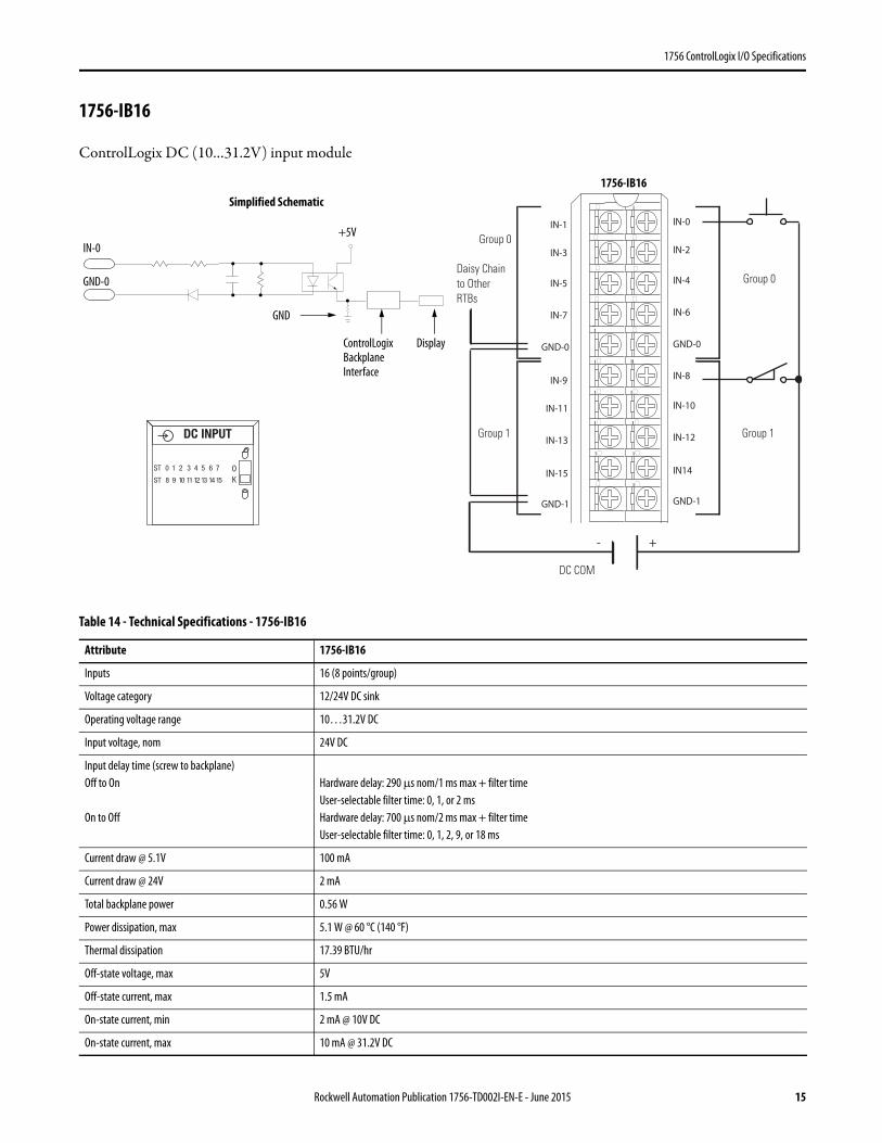
1756-IB16
ControlLogix DC (10…31.2V) input module
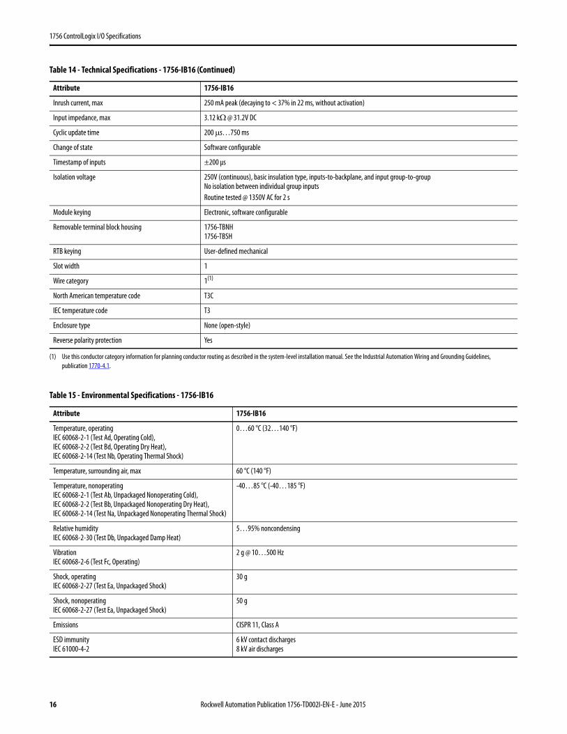
Table 14 - Technical Specifications - 1756-IB16
Attribute 1756-IB16
Inputs 16 (8 points/group)
Voltage category 12/24V DC sink
Operating voltage range 10…31.2V DC
Input voltage, nom 24V DC
Input delay time (screw to backplane)Off to On
On to Off
Hardware delay: 290 μs nom/1 ms max + filter timeUser-selectable filter time: 0, 1, or 2 msHardware delay: 700 μs nom/2 ms max + filter timeUser-selectable filter time: 0, 1, 2, 9, or 18 ms
Current draw @ 5.1V 100 mA
Current draw @ 24V 2 mA
Total backplane power 0.56 W
Power dissipation, max 5.1 W @ 60 °C (140 °F)
Thermal dissipation 17.39 BTU/hr
Off-state voltage, max 5V
Off-state current, max 1.5 mA
On-state current, min 2 mA @ 10V DC
On-state current, max 10 mA @ 31.2V DC
IN-9
IN-11
IN-13
IN-15
GND-1
IN-1
IN-3
IN-5
IN-7
GND-0
IN-8
IN-10
IN-12
IN14
GND-1
IN-0
IN-2
IN-4
IN-6
GND-0
�
��
��
��
�
�
��
��
��
��
Daisy Chain to Other RTBs
Group 0
Group 0
Group 1Group 1
DC COM
- +
ControlLogix Backplane Interface
Simplified Schematic
Display
GND
GND-0
IN-0+5V
DC INPUT
ST 0 1 2 3 4 5 6 7
ST 8 9 10 11 12 13 14 15
OK
1756-IB16
Rockwell Automation Publication 1756-TD002I-EN-E - June 2015 15
1756 ControlLogix I/O Specifications
Inrush current, max 250 mA peak (decaying to < 37% in 22 ms, without activation)
Input impedance, max 3.12 kΩ @ 31.2V DC
Cyclic update time 200 μs…750 ms
Change of state Software configurable
Timestamp of inputs ±200 μs
Isolation voltage 250V (continuous), basic insulation type, inputs-to-backplane, and input group-to-groupNo isolation between individual group inputsRoutine tested @ 1350V AC for 2 s
Module keying Electronic, software configurable
Removable terminal block housing 1756-TBNH1756-TBSH
RTB keying User-defined mechanical
Slot width 1
Wire category 1(1)
North American temperature code T3C
IEC temperature code T3
Enclosure type None (open-style)
Reverse polarity protection Yes
(1) Use this conductor category information for planning conductor routing as described in the system-level installation manual. See the Industrial Automation Wiring and Grounding Guidelines, publication 1770-4.1.
Table 15 - Environmental Specifications - 1756-IB16
Attribute 1756-IB16
Temperature, operatingIEC 60068-2-1 (Test Ad, Operating Cold),IEC 60068-2-2 (Test Bd, Operating Dry Heat),IEC 60068-2-14 (Test Nb, Operating Thermal Shock)
0…60 °C (32…140 °F)
Temperature, surrounding air, max 60 °C (140 °F)
Temperature, nonoperatingIEC 60068-2-1 (Test Ab, Unpackaged Nonoperating Cold),IEC 60068-2-2 (Test Bb, Unpackaged Nonoperating Dry Heat),IEC 60068-2-14 (Test Na, Unpackaged Nonoperating Thermal Shock)
-40…85 °C (-40…185 °F)
Relative humidityIEC 60068-2-30 (Test Db, Unpackaged Damp Heat)
5…95% noncondensing
VibrationIEC 60068-2-6 (Test Fc, Operating)
2 g @ 10…500 Hz
Shock, operatingIEC 60068-2-27 (Test Ea, Unpackaged Shock)
30 g
Shock, nonoperatingIEC 60068-2-27 (Test Ea, Unpackaged Shock)
50 g
Emissions CISPR 11, Class A
ESD immunityIEC 61000-4-2
6 kV contact discharges8 kV air discharges
Table 14 - Technical Specifications - 1756-IB16 (Continued)
Attribute 1756-IB16
16 Rockwell Automation Publication 1756-TD002I-EN-E - June 2015
1756 ControlLogix I/O Specifications
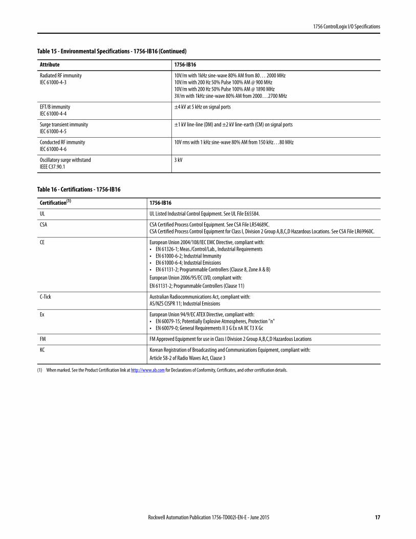
Radiated RF immunityIEC 61000-4-3
10V/m with 1kHz sine-wave 80% AM from 80… 2000 MHz10V/m with 200 Hz 50% Pulse 100% AM @ 900 MHz10V/m with 200 Hz 50% Pulse 100% AM @ 1890 MHz3V/m with 1kHz sine-wave 80% AM from 2000…2700 MHz
EFT/B immunityIEC 61000-4-4
±4 kV at 5 kHz on signal ports
Surge transient immunityIEC 61000-4-5
±1 kV line-line (DM) and ±2 kV line-earth (CM) on signal ports
Conducted RF immunityIEC 61000-4-6
10V rms with 1 kHz sine-wave 80% AM from 150 kHz…80 MHz
Oscillatory surge withstandIEEE C37.90.1
3 kV
Table 16 - Certifications - 1756-IB16
Certification(1)
(1) When marked. See the Product Certification link at http://www.ab.com for Declarations of Conformity, Certificates, and other certification details.
1756-IB16
UL UL Listed Industrial Control Equipment. See UL File E65584.
CSA CSA Certified Process Control Equipment. See CSA File LR54689C.CSA Certified Process Control Equipment for Class I, Division 2 Group A,B,C,D Hazardous Locations. See CSA File LR69960C.
CE European Union 2004/108/IEC EMC Directive, compliant with:• EN 61326-1; Meas./Control/Lab., Industrial Requirements• EN 61000-6-2; Industrial Immunity• EN 61000-6-4; Industrial Emissions• EN 61131-2; Programmable Controllers (Clause 8, Zone A & B)European Union 2006/95/EC LVD, compliant with:EN 61131-2; Programmable Controllers (Clause 11)
C-Tick Australian Radiocommunications Act, compliant with:AS/NZS CISPR 11; Industrial Emissions
Ex European Union 94/9/EC ATEX Directive, compliant with:• EN 60079-15; Potentially Explosive Atmospheres, Protection "n"• EN 60079-0; General Requirements II 3 G Ex nA IIC T3 X Gc
FM FM Approved Equipment for use in Class I Division 2 Group A,B,C,D Hazardous Locations
KC Korean Registration of Broadcasting and Communications Equipment, compliant with:Article 58-2 of Radio Waves Act, Clause 3
Table 15 - Environmental Specifications - 1756-IB16 (Continued)
Attribute 1756-IB16
Rockwell Automation Publication 1756-TD002I-EN-E - June 2015 17

1756 ControlLogix I/O Specifications
1756-IB16D
ControlLogix DC (10…30V) diagnostic input module
Table 17 - Diagnostic Specifications - 1756-IB16D
Attribute 1756-IB16D
Open wire Off-state leakage current 1.2 mA min
Timestamp of diagnostics ±1 ms
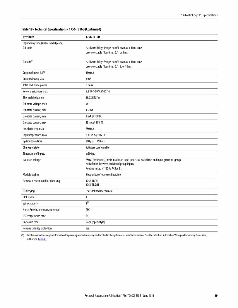
Table 18 - Technical Specifications - 1756-IB16D
Attribute 1756-IB16D
Inputs 16 diagnostic (4 points/group)
Voltage category 12/24V DC sink
Operating voltage range 10…30V DC
Input voltage, nom 24V DC
12
34
56
78
910
1112
1314
1516
1718
1920
2122
2324
2526
2728
2930
3132
3334
3536
+–
Leakage Resistor
Leakage Resistor
Daisy Chain to Other RTBs
Group 0
Group 1
Group 2
Group 3
Group
Group
Group
Group
IN-0IN-1IN-2
IN-3
IN-8
IN-4IN-5
IN-6
IN-7
Not Used
IN-9IN-10
IN-11IN-12
IN-13
IN-14IN-15Not Used
GND-0GND-0GND-0
GND-0
GND-2
GND-1GND-1
GND-1
GND-1
Not Used
GND-2GND-2
GND-2GND-3
GND-3
GND-3GND-3GND-3
DC COM
ControlLogix Backplane Interface
Simplified Schematic
Display
GND
Open Wire
GND-0
IN-0
Input +5V
FLT 8 9 10 11 12 13 14 15
ST 0 1 2 3 4 5 6 7
ST 8 9 10 11 12 13 14 15
OK
FLT 0 1 2 3 4 5 6 7
DC INPUT
DIAGNOSTIC
Recommended Leakage Resistor Size 1/4 W, 5% Supply Voltage
3.9K 10V DC
5.6K 12V DC
15K 24V DC
20K 30V DC
1756-IB16D
18 Rockwell Automation Publication 1756-TD002I-EN-E - June 2015
1756 ControlLogix I/O Specifications
Input delay time (screw to backplane)Off to On
On to Off
Hardware delay: 340 μs nom/1 ms max + filter timeUser-selectable filter time: 0, 1, or 2 ms
Hardware delay: 740 μs nom/4 ms max + filter timeUser-selectable filter time: 0, 1, 9, or 18 ms
Current draw @ 5.1V 150 mA
Current draw @ 24V 3 mA
Total backplane power 0.84 W
Power dissipation, max 5.8 W @ 60 °C (140 °F)
Thermal dissipation 19.78 BTU/hr
Off-state voltage, max 5V
Off-state current, max 1.5 mA
On-state current, min 2 mA @ 10V DC
On-state current, max 13 mA @ 30V DC
Inrush current, max 250 mA
Input impedance, max 2.31 kΩ @ 30V DC
Cyclic update time 200 μs…750 ms
Change of state Software configurable
Timestamp of inputs ±200 μs
Isolation voltage 250V (continuous), basic insulation type, inputs-to-backplane, and input group-to-groupNo isolation between individual group inputsRoutine tested @ 1350V AC for 2 s
Module keying Electronic, software configurable
Removable terminal block housing 1756-TBCH1756-TBS6H
RTB keying User-defined mechanical
Slot width 1
Wire category 1(1)
North American temperature code T3C
IEC temperature code T3
Enclosure type None (open-style)
Reverse polarity protection Yes
(1) Use this conductor category information for planning conductor routing as described in the system-level installation manual. See the Industrial Automation Wiring and Grounding Guidelines, publication 1770-4.1.
Table 18 - Technical Specifications - 1756-IB16D (Continued)
Attribute 1756-IB16D
Rockwell Automation Publication 1756-TD002I-EN-E - June 2015 19

1756 ControlLogix I/O Specifications
Table 19 - Environmental Specifications - 1756-IB16D
Attribute 1756-IB16D
Temperature, operatingIEC 60068-2-1 (Test Ad, Operating Cold),IEC 60068-2-2 (Test Bd, Operating Dry Heat),IEC 60068-2-14 (Test Nb, Operating Thermal Shock)
0…60 °C (32…140 °F)
Temperature, surrounding air, max 60 °C (140 °F)
Temperature, nonoperatingIEC 60068-2-1 (Test Ab, Unpackaged Nonoperating Cold),IEC 60068-2-2 (Test Bb, Unpackaged Nonoperating Dry Heat),IEC 60068-2-14 (Test Na, Unpackaged Nonoperating Thermal Shock)
-40…85 °C (-40…185 °F)
Relative humidityIEC 60068-2-30 (Test Db, Unpackaged Damp Heat)
5…95% noncondensing
VibrationIEC 60068-2-6 (Test Fc, Operating)
2 g @ 10…500 Hz
Shock, operatingIEC 60068-2-27 (Test Ea, Unpackaged Shock)
30 g
Shock, nonoperatingIEC 60068-2-27 (Test Ea, Unpackaged Shock)
50 g
Emissions CISPR 11, Class A
ESD immunityIEC 61000-4-2
6 kV contact discharges8 kV air discharges
Radiated RF immunityIEC 61000-4-3
10V/m with 1 kHz sine-wave 80% AM from 80… 2000 MHz10V/m with 200 Hz 50% Pulse 100% AM @ 900 MHz10V/m with 200 Hz 50% Pulse 100% AM @ 1890 MHz3V/m with 1 kHz sine-wave 80% AM from 2000…2700 MHz
EFT/B immunityIEC 61000-4-4
±4 kV at 5 kHz on signal ports
Surge transient immunityIEC 61000-4-5
±1 kV line-line (DM) and ±2 kV line-earth (CM) on signal ports
Conducted RF immunityIEC 61000-4-6
10V rms with 1 kHz sine-wave 80% AM from 150 kHz…80 MHz
20 Rockwell Automation Publication 1756-TD002I-EN-E - June 2015
1756 ControlLogix I/O Specifications
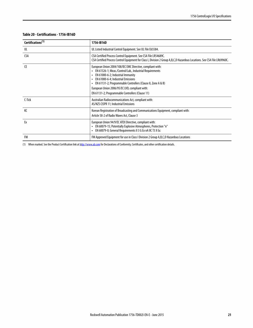
Table 20 - Certifications - 1756-IB16D
Certifications(1)
(1) When marked. See the Product Certification link at http://www.ab.com for Declarations of Conformity, Certificates, and other certification details.
1756-IB16D
UL UL Listed Industrial Control Equipment. See UL File E65584.
CSA CSA Certified Process Control Equipment. See CSA File LR54689C.CSA Certified Process Control Equipment for Class I, Division 2 Group A,B,C,D Hazardous Locations. See CSA File LR69960C.
CE European Union 2004/108/IEC EMC Directive, compliant with:• EN 61326-1; Meas./Control/Lab., Industrial Requirements• EN 61000-6-2; Industrial Immunity• EN 61000-6-4; Industrial Emissions• EN 61131-2; Programmable Controllers (Clause 8, Zone A & B)European Union 2006/95/EC LVD, compliant with:EN 61131-2; Programmable Controllers (Clause 11)
C-Tick Australian Radiocommunications Act, compliant with:AS/NZS CISPR 11; Industrial Emissions
KC Korean Registration of Broadcasting and Communications Equipment, compliant with:Article 58-2 of Radio Waves Act, Clause 3
Ex European Union 94/9/EC ATEX Directive, compliant with:• EN 60079-15; Potentially Explosive Atmospheres, Protection "n"• EN 60079-0; General Requirements II 3 G Ex nA IIC T3 X Gc
FM FM Approved Equipment for use in Class I Division 2 Group A,B,C,D Hazardous Locations
Rockwell Automation Publication 1756-TD002I-EN-E - June 2015 21
1756 ControlLogix I/O Specifications
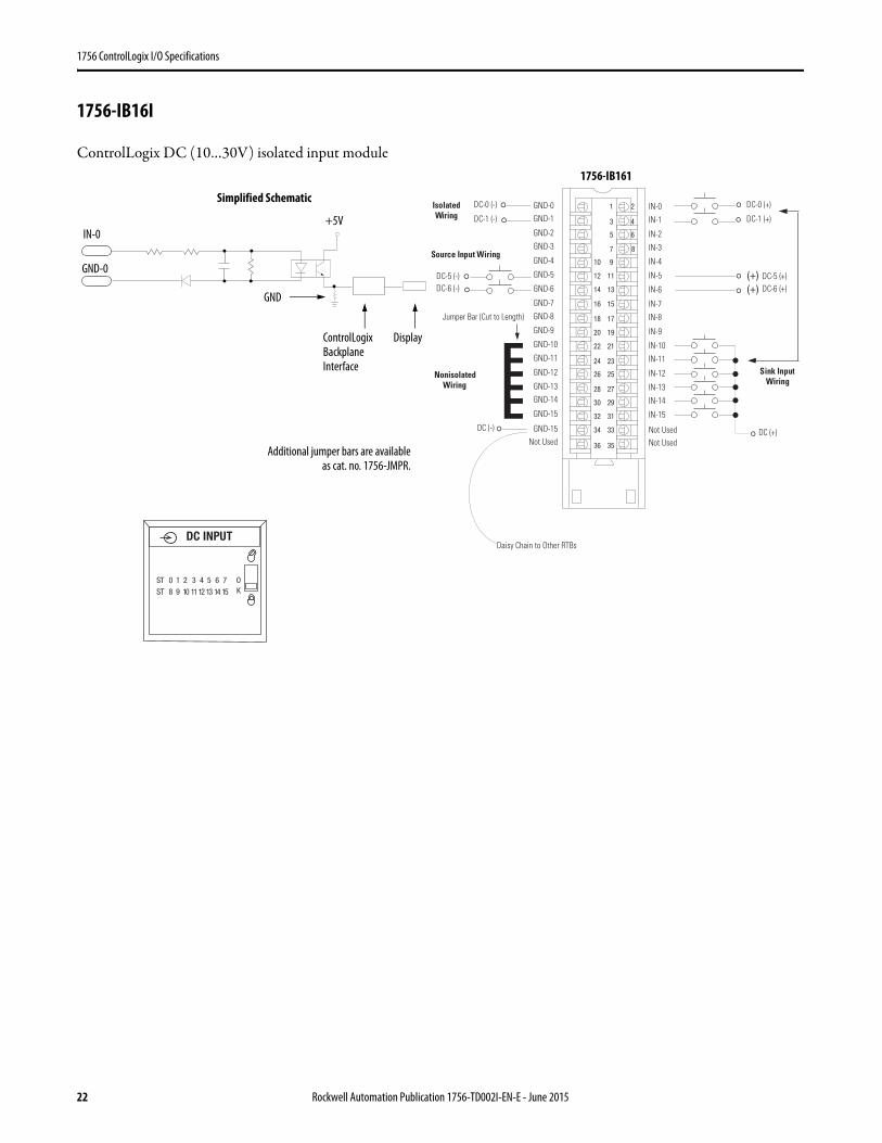
1756-IB16I
ControlLogix DC (10…30V) isolated input module
1 2
3 4
5 6
7 8
01 9
21 11
41 31
61 51
81 71
02 91
22 12
42 32
62 52
82 72
03 92
23 13
43 33
63 53
(+)(+)
NonisolatedWiring
IsolatedWiring
Daisy Chain to Other RTBs
GND-0GND-1
GND-2
GND-3
GND-8
GND-4
GND-5
GND-6
GND-7
Not Used
GND-9
GND-10
GND-11
GND-12
GND-13GND-14
GND-15
GND-15
IN-0
IN-1
IN-2
IN-3
IN-8
IN-4
IN-5
IN-6
IN-7
Not Used
IN-9
IN-10
IN-11
IN-12
IN-13
IN-14
IN-15
Not Used
DC-5 (-)
DC (-)
Jumper Bar (Cut to Length)
DC-6 (-)DC-5 (+)DC-6 (+)
DC (+)
DC-0 (+)
DC-1 (+)
DC-0 (-)
DC-1 (-)
Source Input Wiring
Sink Input Wiring
ControlLogix Backplane Interface
Simplified Schematic
Display
GND-0
GND
IN-0+5V
Additional jumper bars are availableas cat. no. 1756-JMPR.
DC INPUT
ST 0 1 2 3 4 5 6 7
ST 8 9 10 1112 13 14 15
OK
1756-IB161
22 Rockwell Automation Publication 1756-TD002I-EN-E - June 2015
1756 ControlLogix I/O Specifications
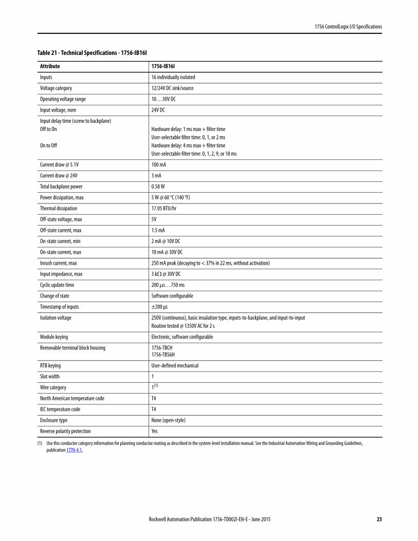
Table 21 - Technical Specifications - 1756-IB16I
Attribute 1756-IB16I
Inputs 16 individually isolated
Voltage category 12/24V DC sink/source
Operating voltage range 10…30V DC
Input voltage, nom 24V DC
Input delay time (screw to backplane)Off to On
On to Off
Hardware delay: 1 ms max + filter timeUser-selectable filter time: 0, 1, or 2 msHardware delay: 4 ms max + filter timeUser-selectable filter time: 0, 1, 2, 9, or 18 ms
Current draw @ 5.1V 100 mA
Current draw @ 24V 3 mA
Total backplane power 0.58 W
Power dissipation, max 5 W @ 60 °C (140 °F)
Thermal dissipation 17.05 BTU/hr
Off-state voltage, max 5V
Off-state current, max 1.5 mA
On-state current, min 2 mA @ 10V DC
On-state current, max 10 mA @ 30V DC
Inrush current, max 250 mA peak (decaying to < 37% in 22 ms, without activation)
Input impedance, max 3 kΩ @ 30V DC
Cyclic update time 200 μs…750 ms
Change of state Software configurable
Timestamp of inputs ±200 μs
Isolation voltage 250V (continuous), basic insulation type, inputs-to-backplane, and input-to-inputRoutine tested @ 1350V AC for 2 s
Module keying Electronic, software configurable
Removable terminal block housing 1756-TBCH1756-TBS6H
RTB keying User-defined mechanical
Slot width 1
Wire category 1(1)
(1) Use this conductor category information for planning conductor routing as described in the system-level installation manual. See the Industrial Automation Wiring and Grounding Guidelines, publication 1770-4.1.
North American temperature code T4
IEC temperature code T4
Enclosure type None (open-style)
Reverse polarity protection Yes
Rockwell Automation Publication 1756-TD002I-EN-E - June 2015 23
1756 ControlLogix I/O Specifications
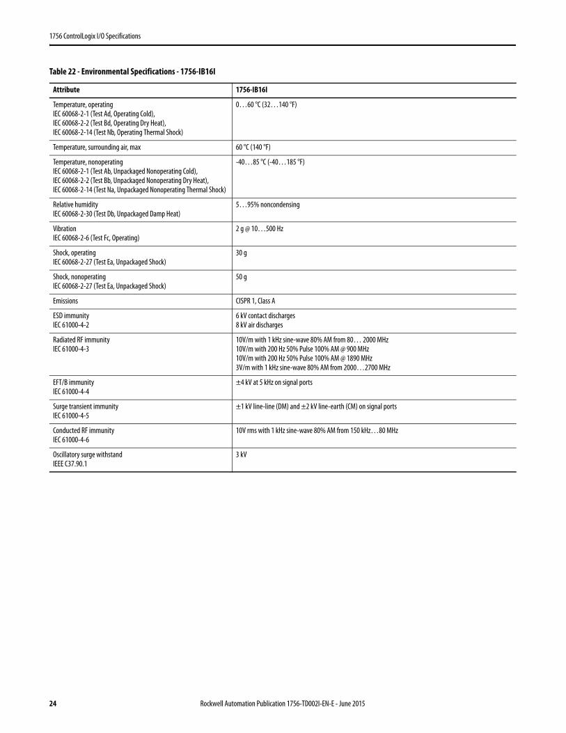
Table 22 - Environmental Specifications - 1756-IB16I
Attribute 1756-IB16I
Temperature, operatingIEC 60068-2-1 (Test Ad, Operating Cold),IEC 60068-2-2 (Test Bd, Operating Dry Heat),IEC 60068-2-14 (Test Nb, Operating Thermal Shock)
0…60 °C (32…140 °F)
Temperature, surrounding air, max 60 °C (140 °F)
Temperature, nonoperatingIEC 60068-2-1 (Test Ab, Unpackaged Nonoperating Cold),IEC 60068-2-2 (Test Bb, Unpackaged Nonoperating Dry Heat),IEC 60068-2-14 (Test Na, Unpackaged Nonoperating Thermal Shock)
-40…85 °C (-40…185 °F)
Relative humidityIEC 60068-2-30 (Test Db, Unpackaged Damp Heat)
5…95% noncondensing
VibrationIEC 60068-2-6 (Test Fc, Operating)
2 g @ 10…500 Hz
Shock, operatingIEC 60068-2-27 (Test Ea, Unpackaged Shock)
30 g
Shock, nonoperatingIEC 60068-2-27 (Test Ea, Unpackaged Shock)
50 g
Emissions CISPR 1, Class A
ESD immunityIEC 61000-4-2
6 kV contact discharges8 kV air discharges
Radiated RF immunityIEC 61000-4-3
10V/m with 1 kHz sine-wave 80% AM from 80… 2000 MHz10V/m with 200 Hz 50% Pulse 100% AM @ 900 MHz10V/m with 200 Hz 50% Pulse 100% AM @ 1890 MHz3V/m with 1 kHz sine-wave 80% AM from 2000…2700 MHz
EFT/B immunityIEC 61000-4-4
±4 kV at 5 kHz on signal ports
Surge transient immunityIEC 61000-4-5
±1 kV line-line (DM) and ±2 kV line-earth (CM) on signal ports
Conducted RF immunityIEC 61000-4-6
10V rms with 1 kHz sine-wave 80% AM from 150 kHz…80 MHz
Oscillatory surge withstandIEEE C37.90.1
3 kV
24 Rockwell Automation Publication 1756-TD002I-EN-E - June 2015

1756 ControlLogix I/O Specifications
Table 23 - Certifications - 1756-IB16I
Certification(1)
(1) When marked. See the Product Certification link at http://www.ab.com for Declarations of Conformity, Certificates, and other certification details.
1756-IB16I
UL UL Listed Industrial Control Equipment. See UL File E65584.
CSA CSA Certified Process Control Equipment. See CSA File LR54689C.CSA Certified Process Control Equipment for Class I, Division 2 Group A,B,C,D Hazardous Locations. See CSA File LR69960C.
CE European Union 2004/108/IEC EMC Directive, compliant with:• EN 61326-1; Meas./Control/Lab., Industrial Requirements• EN 61000-6-2; Industrial Immunity• EN 61000-6-4; Industrial Emissions• EN 61131-2; Programmable Controllers (Clause 8, Zone A & B)European Union 2006/95/EC LVD, compliant with:EN 61131-2; Programmable Controllers (Clause 11)
C-Tick Australian Radiocommunications Act, compliant with:AS/NZS CISPR 11; Industrial Emissions
Ex European Union 94/9/EC ATEX Directive, compliant with:• EN 60079-15; Potentially Explosive Atmospheres, Protection "n"• EN 60079-0; General Requirements II 3 G Ex nA IIC T4 X Gc
FM FM Approved Equipment for use in Class I Division 2 Group A,B,C,D Hazardous Locations
KC Korean Registration of Broadcasting and Communications Equipment, compliant with:Article 58-2 of Radio Waves Act, Clause 3
Rockwell Automation Publication 1756-TD002I-EN-E - June 2015 25
1756 ControlLogix I/O Specifications
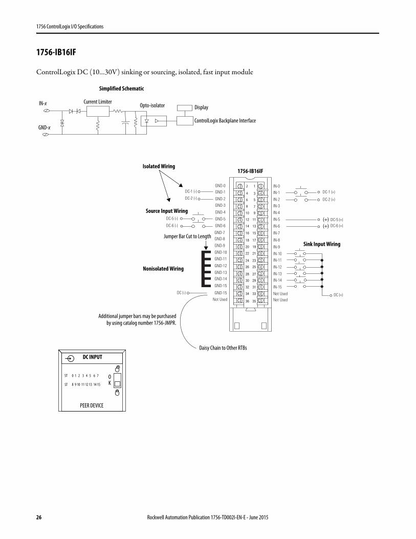
1756-IB16IF
ControlLogix DC (10…30V) sinking or sourcing, isolated, fast input module
1
3
5
7
01 9
21 11
41 31
61 51
81 71
02 91
22 12
42 32
62 52
82 72
03 92
23 13
43 33
63 53
(+)(+)
GND-0GND-1
GND-2
GND-3
GND-4
GND-5
GND-6
GND-7
Not Used
IN-0
IN-1
IN-2
IN-3
IN-4
IN-5
IN-6
IN-7
Not UsedNot Used
DC-5 (-)
DC (-)
DC-6 (-)DC-5 (+)DC-6 (+)
DC (+)
DC-1 (+)
DC-2 (+)
DC-1 (-)
DC-2 (-)
2
4
6
8
GND-8
GND-9
GND-10
GND-11
GND-12
GND-13GND-14
GND-15
GND-15
IN-8
IN-9
IN-10
IN-11
IN-12
IN-13
IN-14
IN-15
Simplified Schematic
ControlLogix Backplane Interface
Display
GND-x
IN-x
1756-IB16IF
Current Limiter
Daisy Chain to Other RTBs
Source Input Wiring
Jumper Bar Cut to Length
Nonisolated Wiring
Isolated Wiring
Sink Input Wiring
Additional jumper bars may be purchasedby using catalog number 1756-JMPR.
DC INPUT
PEER DEVICE
O0 1 2 3 4 5 6 7
8 9 10 11 12 13 14 15 KST
ST
Opto-isolator
26 Rockwell Automation Publication 1756-TD002I-EN-E - June 2015
1756 ControlLogix I/O Specifications
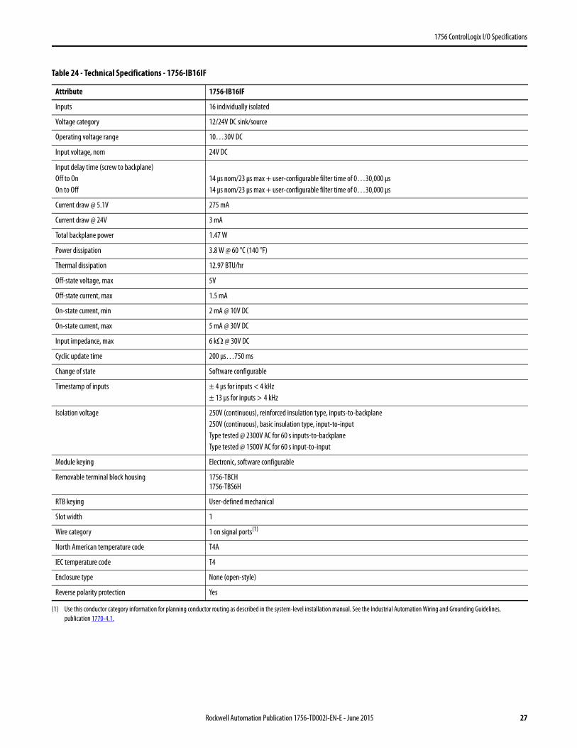
Table 24 - Technical Specifications - 1756-IB16IF
Attribute 1756-IB16IF
Inputs 16 individually isolated
Voltage category 12/24V DC sink/source
Operating voltage range 10…30V DC
Input voltage, nom 24V DC
Input delay time (screw to backplane)Off to OnOn to Off
14 μs nom/23 μs max + user-configurable filter time of 0…30,000 μs14 μs nom/23 μs max + user-configurable filter time of 0…30,000 μs
Current draw @ 5.1V 275 mA
Current draw @ 24V 3 mA
Total backplane power 1.47 W
Power dissipation 3.8 W @ 60 °C (140 °F)
Thermal dissipation 12.97 BTU/hr
Off-state voltage, max 5V
Off-state current, max 1.5 mA
On-state current, min 2 mA @ 10V DC
On-state current, max 5 mA @ 30V DC
Input impedance, max 6 kΩ @ 30V DC
Cyclic update time 200 μs…750 ms
Change of state Software configurable
Timestamp of inputs ± 4 μs for inputs < 4 kHz± 13 μs for inputs > 4 kHz
Isolation voltage 250V (continuous), reinforced insulation type, inputs-to-backplane250V (continuous), basic insulation type, input-to-inputType tested @ 2300V AC for 60 s inputs-to-backplaneType tested @ 1500V AC for 60 s input-to-input
Module keying Electronic, software configurable
Removable terminal block housing 1756-TBCH1756-TBS6H
RTB keying User-defined mechanical
Slot width 1
Wire category 1 on signal ports(1)
(1) Use this conductor category information for planning conductor routing as described in the system-level installation manual. See the Industrial Automation Wiring and Grounding Guidelines, publication 1770-4.1.
North American temperature code T4A
IEC temperature code T4
Enclosure type None (open-style)
Reverse polarity protection Yes
Rockwell Automation Publication 1756-TD002I-EN-E - June 2015 27

1756 ControlLogix I/O Specifications
Table 25 - Environmental Specifications - 1756-IB16IF
Attribute 1756-IB16IF
Temperature, operatingIEC 60068-2-1 (Test Ad, Operating Cold),IEC 60068-2-2 (Test Bd, Operating Dry Heat),IEC 60068-2-14 (Test Nb, Operating Thermal Shock)
0…60 °C (32…140 °F)
Temperature, surrounding air, max 60 °C (140 °F)
Temperature, nonoperatingIEC 60068-2-1 (Test Ab, Unpackaged Nonoperating Cold),IEC 60068-2-2 (Test Bb, Unpackaged Nonoperating Dry Heat),IEC 60068-2-14 (Test Na, Unpackaged Nonoperating Thermal Shock)
-40…85 °C (-40…185 °F)
Relative humidityIEC 60068-2-30 (Test Db, Unpackaged Damp Heat)
5…95% noncondensing
VibrationIEC 60068-2-6 (Test Fc, Operating)
2 g @ 10…500 Hz
Shock, operatingIEC 60068-2-27 (Test Ea, Unpackaged Shock)
30 g
Shock, nonoperatingIEC 60068-2-27 (Test Ea, Unpackaged Shock)
50 g
Emissions CISPR 1, Class A
ESD immunityIEC 61000-4-2
6 kV contact discharges8 kV air discharges
Radiated RF immunityIEC 61000-4-3
10V/m with 1 kHz sine-wave 80% AM from 80… 2000 MHz10V/m with 200 Hz 50% Pulse 100% AM @ 900 MHz10V/m with 200 Hz 50% Pulse 100% AM @ 1890 MHz3V/m with 1 kHz sine-wave 80% AM from 2000…2700 MHz
EFT/B immunityIEC 61000-4-4
±4 kV at 5 kHz on signal ports
Surge transient immunityIEC 61000-4-5
±1 kV line-line (DM) and ±2 kV line-earth (CM) on signal ports
Conducted RF immunityIEC 61000-4-6
10V rms with 1 kHz sine-wave 80% AM from 150 kHz…80 MHz
28 Rockwell Automation Publication 1756-TD002I-EN-E - June 2015
1756 ControlLogix I/O Specifications
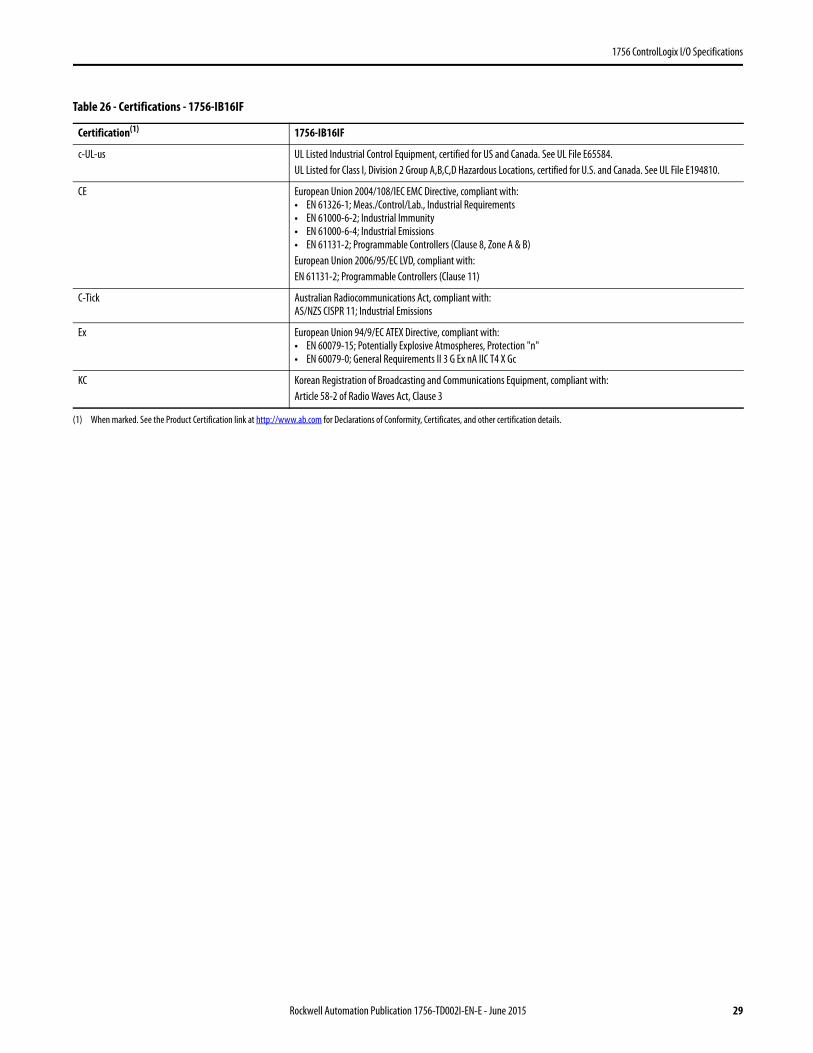
Table 26 - Certifications - 1756-IB16IF
Certification(1)
(1) When marked. See the Product Certification link at http://www.ab.com for Declarations of Conformity, Certificates, and other certification details.
1756-IB16IF
c-UL-us UL Listed Industrial Control Equipment, certified for US and Canada. See UL File E65584.UL Listed for Class I, Division 2 Group A,B,C,D Hazardous Locations, certified for U.S. and Canada. See UL File E194810.
CE European Union 2004/108/IEC EMC Directive, compliant with:• EN 61326-1; Meas./Control/Lab., Industrial Requirements• EN 61000-6-2; Industrial Immunity• EN 61000-6-4; Industrial Emissions• EN 61131-2; Programmable Controllers (Clause 8, Zone A & B)European Union 2006/95/EC LVD, compliant with:EN 61131-2; Programmable Controllers (Clause 11)
C-Tick Australian Radiocommunications Act, compliant with:AS/NZS CISPR 11; Industrial Emissions
Ex European Union 94/9/EC ATEX Directive, compliant with:• EN 60079-15; Potentially Explosive Atmospheres, Protection "n"• EN 60079-0; General Requirements II 3 G Ex nA IIC T4 X Gc
KC Korean Registration of Broadcasting and Communications Equipment, compliant with:Article 58-2 of Radio Waves Act, Clause 3
Rockwell Automation Publication 1756-TD002I-EN-E - June 2015 29
1756 ControlLogix I/O Specifications
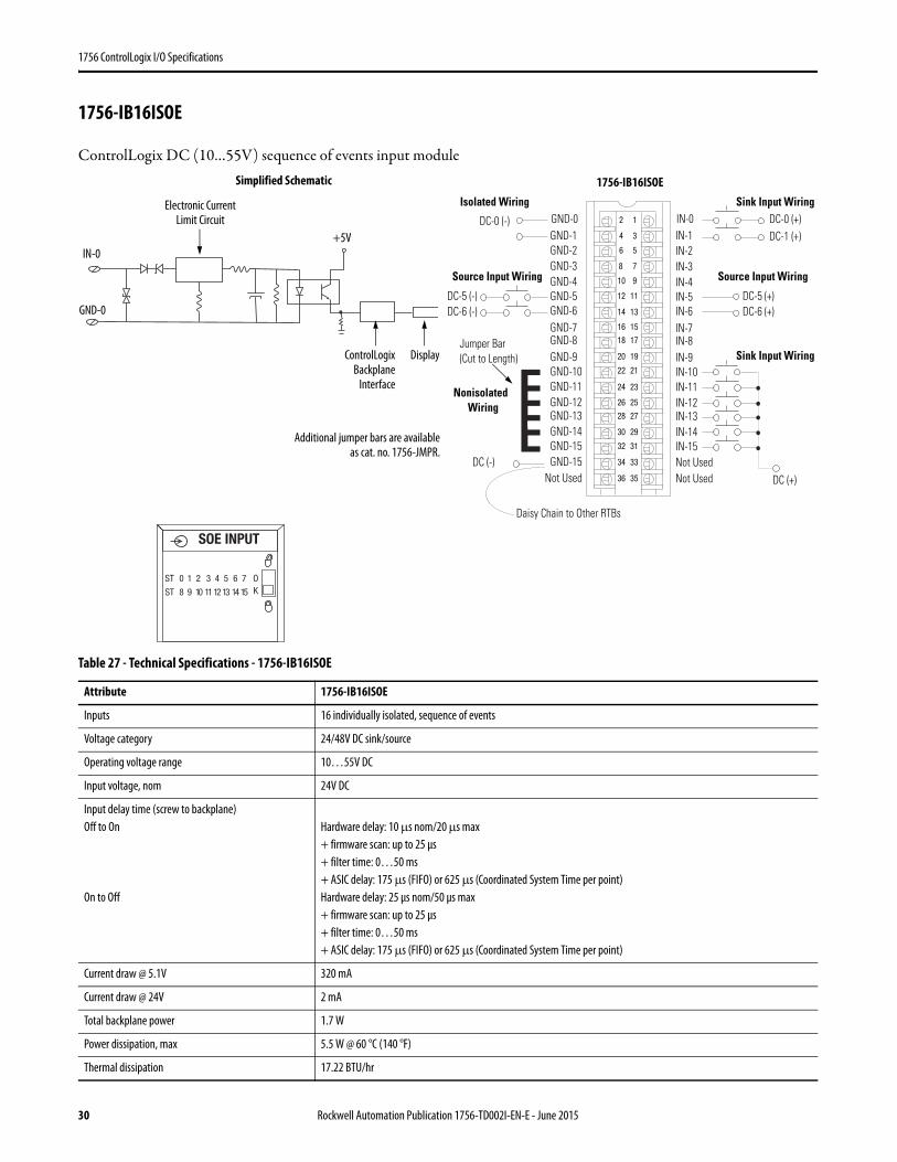
1756-IB16ISOE
ControlLogix DC (10…55V) sequence of events input module
Table 27 - Technical Specifications - 1756-IB16ISOE
Attribute 1756-IB16ISOE
Inputs 16 individually isolated, sequence of events
Voltage category 24/48V DC sink/source
Operating voltage range 10…55V DC
Input voltage, nom 24V DC
Input delay time (screw to backplane)Off to On
On to Off
Hardware delay: 10 μs nom/20 μs max+ firmware scan: up to 25 μs+ filter time: 0…50 ms+ ASIC delay: 175 μs (FIFO) or 625 μs (Coordinated System Time per point)Hardware delay: 25 μs nom/50 μs max+ firmware scan: up to 25 μs+ filter time: 0…50 ms+ ASIC delay: 175 μs (FIFO) or 625 μs (Coordinated System Time per point)
Current draw @ 5.1V 320 mA
Current draw @ 24V 2 mA
Total backplane power 1.7 W
Power dissipation, max 5.5 W @ 60 °C (140 °F)
Thermal dissipation 17.22 BTU/hr
12
34
56
78
910
1112
1314
1516
1718
1920
2122
2324
2526
2728
2930
3132
3334
3536
Nonisolated Wiring
Isolated Wiring
Daisy Chain to Other RTBs
DC (-)
Jumper Bar (Cut to Length)
)+( 6-CD)-( 6-CD
DC (+)
DC-0 (+)DC-1 (+)
DC-0 (-)
DC-5 (-)
IN-0IN-1IN-2IN-3
IN-8
IN-4IN-5IN-6IN-7
Not Used
IN-9IN-10IN-11IN-12IN-13IN-14IN-15Not Used
GND-0GND-1GND-2GND-3
GND-8
GND-4GND-5GND-6GND-7
Not Used
GND-9GND-10GND-11GND-12GND-13GND-14GND-15GND-15
DC-5 (+)
Sink Input Wiring
Source Input WiringSource Input Wiring
Sink Input WiringControlLogixBackplane
Interface
Simplified Schematic
Display
GND-0
IN-0
Electronic Current Limit Circuit
+5V
Additional jumper bars are availableas cat. no. 1756-JMPR.
SOE INPUT
ST 0 1 2 3 4 5 6 7
ST 8 9 10 11 12 13 14 15
OK
1756-IB16ISOE
30 Rockwell Automation Publication 1756-TD002I-EN-E - June 2015
1756 ControlLogix I/O Specifications
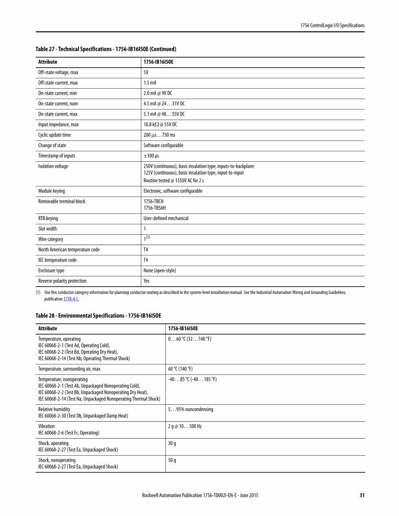
Off-state voltage, max 5V
Off-state current, max 1.5 mA
On-state current, min 2.0 mA @ 9V DC
On-state current, nom 4.5 mA @ 24…31V DC
On-state current, max 5.1 mA @ 48…55V DC
Input impedance, max 10.8 kΩ @ 55V DC
Cyclic update time 200 μs…750 ms
Change of state Software configurable
Timestamp of inputs ±100 μs
Isolation voltage 250V (continuous), basic insulation type, inputs-to-backplane125V (continuous), basic insulation type, input-to-inputRoutine tested @ 1350V AC for 2 s
Module keying Electronic, software configurable
Removable terminal block 1756-TBCH1756-TBS6H
RTB keying User-defined mechanical
Slot width 1
Wire category 1(1)
North American temperature code T4
IEC temperature code T4
Enclosure type None (open-style)
Reverse polarity protection Yes
(1) Use this conductor category information for planning conductor routing as described in the system-level installation manual. See the Industrial Automation Wiring and Grounding Guidelines, publication 1770-4.1.
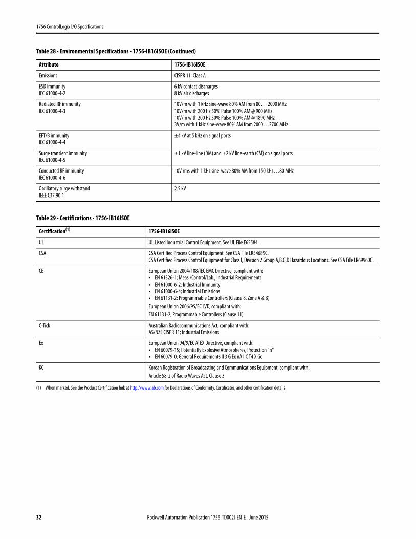
Table 28 - Environmental Specifications - 1756-IB16ISOE
Attribute 1756-IB16ISOE
Temperature, operatingIEC 60068-2-1 (Test Ad, Operating Cold),IEC 60068-2-2 (Test Bd, Operating Dry Heat),IEC 60068-2-14 (Test Nb, Operating Thermal Shock)
0…60 °C (32…140 °F)
Temperature, surrounding air, max 60 °C (140 °F)
Temperature, nonoperatingIEC 60068-2-1 (Test Ab, Unpackaged Nonoperating Cold),IEC 60068-2-2 (Test Bb, Unpackaged Nonoperating Dry Heat),IEC 60068-2-14 (Test Na, Unpackaged Nonoperating Thermal Shock)
-40…85 °C (-40…185 °F)
Relative humidityIEC 60068-2-30 (Test Db, Unpackaged Damp Heat)
5…95% noncondensing
VibrationIEC 60068-2-6 (Test Fc, Operating)
2 g @ 10…500 Hz
Shock, operatingIEC 60068-2-27 (Test Ea, Unpackaged Shock)
30 g
Shock, nonoperatingIEC 60068-2-27 (Test Ea, Unpackaged Shock)
50 g
Table 27 - Technical Specifications - 1756-IB16ISOE (Continued)
Attribute 1756-IB16ISOE
Rockwell Automation Publication 1756-TD002I-EN-E - June 2015 31
1756 ControlLogix I/O Specifications
Emissions CISPR 11, Class A
ESD immunityIEC 61000-4-2
6 kV contact discharges8 kV air discharges
Radiated RF immunityIEC 61000-4-3
10V/m with 1 kHz sine-wave 80% AM from 80… 2000 MHz10V/m with 200 Hz 50% Pulse 100% AM @ 900 MHz10V/m with 200 Hz 50% Pulse 100% AM @ 1890 MHz3V/m with 1 kHz sine-wave 80% AM from 2000…2700 MHz
EFT/B immunityIEC 61000-4-4
±4 kV at 5 kHz on signal ports
Surge transient immunityIEC 61000-4-5
±1 kV line-line (DM) and ±2 kV line-earth (CM) on signal ports
Conducted RF immunityIEC 61000-4-6
10V rms with 1 kHz sine-wave 80% AM from 150 kHz…80 MHz
Oscillatory surge withstandIEEE C37.90.1
2.5 kV
Table 29 - Certifications - 1756-IB16ISOE
Certification(1)
(1) When marked. See the Product Certification link at http://www.ab.com for Declarations of Conformity, Certificates, and other certification details.
1756-IB16ISOE
UL UL Listed Industrial Control Equipment. See UL File E65584.
CSA CSA Certified Process Control Equipment. See CSA File LR54689C.CSA Certified Process Control Equipment for Class I, Division 2 Group A,B,C,D Hazardous Locations. See CSA File LR69960C.
CE European Union 2004/108/IEC EMC Directive, compliant with:• EN 61326-1; Meas./Control/Lab., Industrial Requirements• EN 61000-6-2; Industrial Immunity• EN 61000-6-4; Industrial Emissions• EN 61131-2; Programmable Controllers (Clause 8, Zone A & B)European Union 2006/95/EC LVD, compliant with:EN 61131-2; Programmable Controllers (Clause 11)
C-Tick Australian Radiocommunications Act, compliant with:AS/NZS CISPR 11; Industrial Emissions
Ex European Union 94/9/EC ATEX Directive, compliant with:• EN 60079-15; Potentially Explosive Atmospheres, Protection "n"• EN 60079-0; General Requirements II 3 G Ex nA IIC T4 X Gc
KC Korean Registration of Broadcasting and Communications Equipment, compliant with:Article 58-2 of Radio Waves Act, Clause 3
Table 28 - Environmental Specifications - 1756-IB16ISOE (Continued)
Attribute 1756-IB16ISOE
32 Rockwell Automation Publication 1756-TD002I-EN-E - June 2015
1756 ControlLogix I/O Specifications
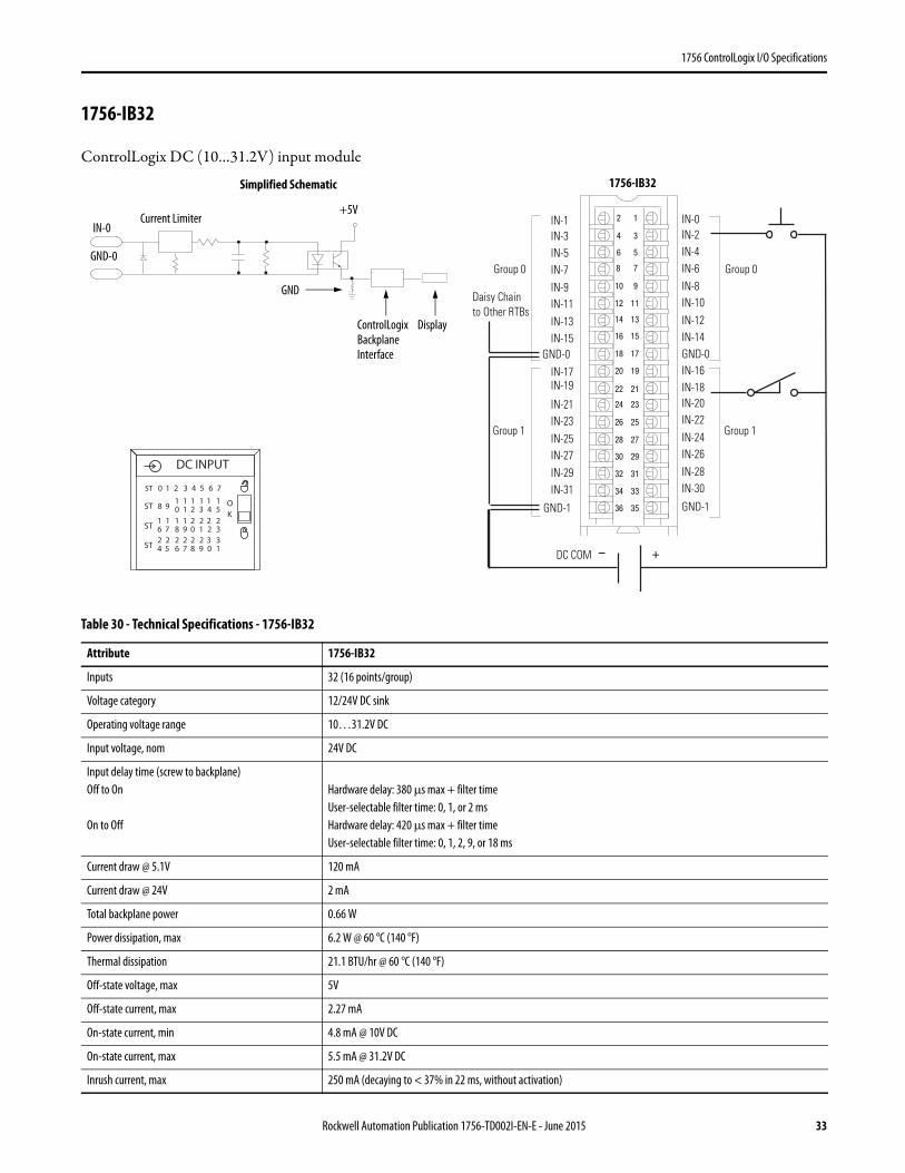
1756-IB32
ControlLogix DC (10…31.2V) input module
Table 30 - Technical Specifications - 1756-IB32
Attribute 1756-IB32
Inputs 32 (16 points/group)
Voltage category 12/24V DC sink
Operating voltage range 10…31.2V DC
Input voltage, nom 24V DC
Input delay time (screw to backplane)Off to On
On to Off
Hardware delay: 380 μs max + filter timeUser-selectable filter time: 0, 1, or 2 msHardware delay: 420 μs max + filter timeUser-selectable filter time: 0, 1, 2, 9, or 18 ms
Current draw @ 5.1V 120 mA
Current draw @ 24V 2 mA
Total backplane power 0.66 W
Power dissipation, max 6.2 W @ 60 °C (140 °F)
Thermal dissipation 21.1 BTU/hr @ 60 °C (140 °F)
Off-state voltage, max 5V
Off-state current, max 2.27 mA
On-state current, min 4.8 mA @ 10V DC
On-state current, max 5.5 mA @ 31.2V DC
Inrush current, max 250 mA (decaying to < 37% in 22 ms, without activation)
12
34
56
78
910
1112
1314
1516
1718
1920
2122
2324
2526
2728
2930
3132
3334
3536
+–
Daisy Chain to Other RTBs
DC COM
0 puorG0 puorG
1 puorG1 puorG
IN-1IN-3IN-5IN-7
GND-0
IN-9IN-11IN-13IN-15
GND-1
IN-17IN-19
IN-21IN-23IN-25IN-27IN-29IN-31
IN-0IN-2IN-4IN-6
GND-0
IN-8IN-10IN-12IN-14
GND-1
IN-16IN-18IN-20IN-22IN-24IN-26IN-28IN-30
ControlLogix Backplane Interface
Simplified Schematic
Display
GND-0
GND
IN-0+5V
DC INPUT
OK
ST 0 1 2 3 4 5 6 7
ST 8 910 21 3 4 5
1 1 1 11
ST 6 718 09 1 2 3
1 2 2 221 1
ST 4 526 87 9 0 1
2 2 2 332 2
Current Limiter
1756-IB32
Rockwell Automation Publication 1756-TD002I-EN-E - June 2015 33
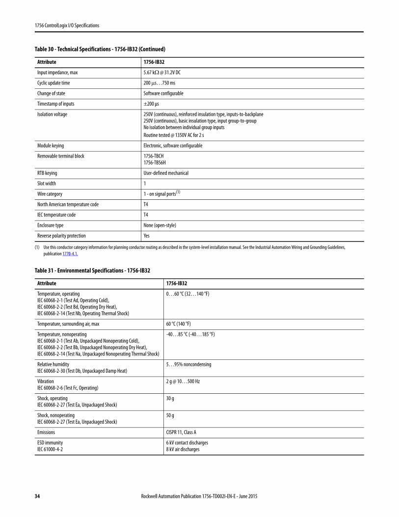
1756 ControlLogix I/O Specifications
Input impedance, max 5.67 kΩ @ 31.2V DC
Cyclic update time 200 μs…750 ms
Change of state Software configurable
Timestamp of inputs ±200 μs
Isolation voltage 250V (continuous), reinforced insulation type, inputs-to-backplane250V (continuous), basic insulation type, input group-to-groupNo isolation between individual group inputsRoutine tested @ 1350V AC for 2 s
Module keying Electronic, software configurable
Removable terminal block 1756-TBCH1756-TBS6H
RTB keying User-defined mechanical
Slot width 1
Wire category 1 - on signal ports(1)
North American temperature code T4
IEC temperature code T4
Enclosure type None (open-style)
Reverse polarity protection Yes
(1) Use this conductor category information for planning conductor routing as described in the system-level installation manual. See the Industrial Automation Wiring and Grounding Guidelines, publication 1770-4.1.
Table 31 - Environmental Specifications - 1756-IB32
Attribute 1756-IB32
Temperature, operatingIEC 60068-2-1 (Test Ad, Operating Cold),IEC 60068-2-2 (Test Bd, Operating Dry Heat),IEC 60068-2-14 (Test Nb, Operating Thermal Shock)
0…60 °C (32…140 °F)
Temperature, surrounding air, max 60 °C (140 °F)
Temperature, nonoperatingIEC 60068-2-1 (Test Ab, Unpackaged Nonoperating Cold),IEC 60068-2-2 (Test Bb, Unpackaged Nonoperating Dry Heat),IEC 60068-2-14 (Test Na, Unpackaged Nonoperating Thermal Shock)
-40…85 °C (-40…185 °F)
Relative humidityIEC 60068-2-30 (Test Db, Unpackaged Damp Heat)
5…95% noncondensing
VibrationIEC 60068-2-6 (Test Fc, Operating)
2 g @ 10…500 Hz
Shock, operatingIEC 60068-2-27 (Test Ea, Unpackaged Shock)
30 g
Shock, nonoperatingIEC 60068-2-27 (Test Ea, Unpackaged Shock)
50 g
Emissions CISPR 11, Class A
ESD immunityIEC 61000-4-2
6 kV contact discharges8 kV air discharges
Table 30 - Technical Specifications - 1756-IB32 (Continued)
Attribute 1756-IB32
34 Rockwell Automation Publication 1756-TD002I-EN-E - June 2015
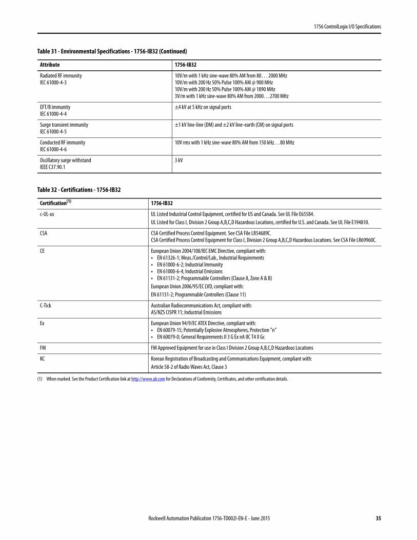
1756 ControlLogix I/O Specifications
Radiated RF immunityIEC 61000-4-3
10V/m with 1 kHz sine-wave 80% AM from 80… 2000 MHz10V/m with 200 Hz 50% Pulse 100% AM @ 900 MHz10V/m with 200 Hz 50% Pulse 100% AM @ 1890 MHz3V/m with 1 kHz sine-wave 80% AM from 2000…2700 MHz
EFT/B immunityIEC 61000-4-4
±4 kV at 5 kHz on signal ports
Surge transient immunityIEC 61000-4-5
±1 kV line-line (DM) and ±2 kV line-earth (CM) on signal ports
Conducted RF immunityIEC 61000-4-6
10V rms with 1 kHz sine-wave 80% AM from 150 kHz…80 MHz
Oscillatory surge withstandIEEE C37.90.1
3 kV
Table 32 - Certifications - 1756-IB32
Certification(1)
(1) When marked. See the Product Certification link at http://www.ab.com for Declarations of Conformity, Certificates, and other certification details.
1756-IB32
c-UL-us UL Listed Industrial Control Equipment, certified for US and Canada. See UL File E65584.UL Listed for Class I, Division 2 Group A,B,C,D Hazardous Locations, certified for U.S. and Canada. See UL File E194810.
CSA CSA Certified Process Control Equipment. See CSA File LR54689C.CSA Certified Process Control Equipment for Class I, Division 2 Group A,B,C,D Hazardous Locations. See CSA File LR69960C.
CE European Union 2004/108/IEC EMC Directive, compliant with:• EN 61326-1; Meas./Control/Lab., Industrial Requirements• EN 61000-6-2; Industrial Immunity• EN 61000-6-4; Industrial Emissions• EN 61131-2; Programmable Controllers (Clause 8, Zone A & B)European Union 2006/95/EC LVD, compliant with:EN 61131-2; Programmable Controllers (Clause 11)
C-Tick Australian Radiocommunications Act, compliant with:AS/NZS CISPR 11; Industrial Emissions
Ex European Union 94/9/EC ATEX Directive, compliant with:• EN 60079-15; Potentially Explosive Atmospheres, Protection "n"• EN 60079-0; General Requirements II 3 G Ex nA IIC T4 X Gc
FM FM Approved Equipment for use in Class I Division 2 Group A,B,C,D Hazardous Locations
KC Korean Registration of Broadcasting and Communications Equipment, compliant with:Article 58-2 of Radio Waves Act, Clause 3
Table 31 - Environmental Specifications - 1756-IB32 (Continued)
Attribute 1756-IB32
Rockwell Automation Publication 1756-TD002I-EN-E - June 2015 35

1756 ControlLogix I/O Specifications
1756-IC16
ControlLogix DC (30…60V) input module
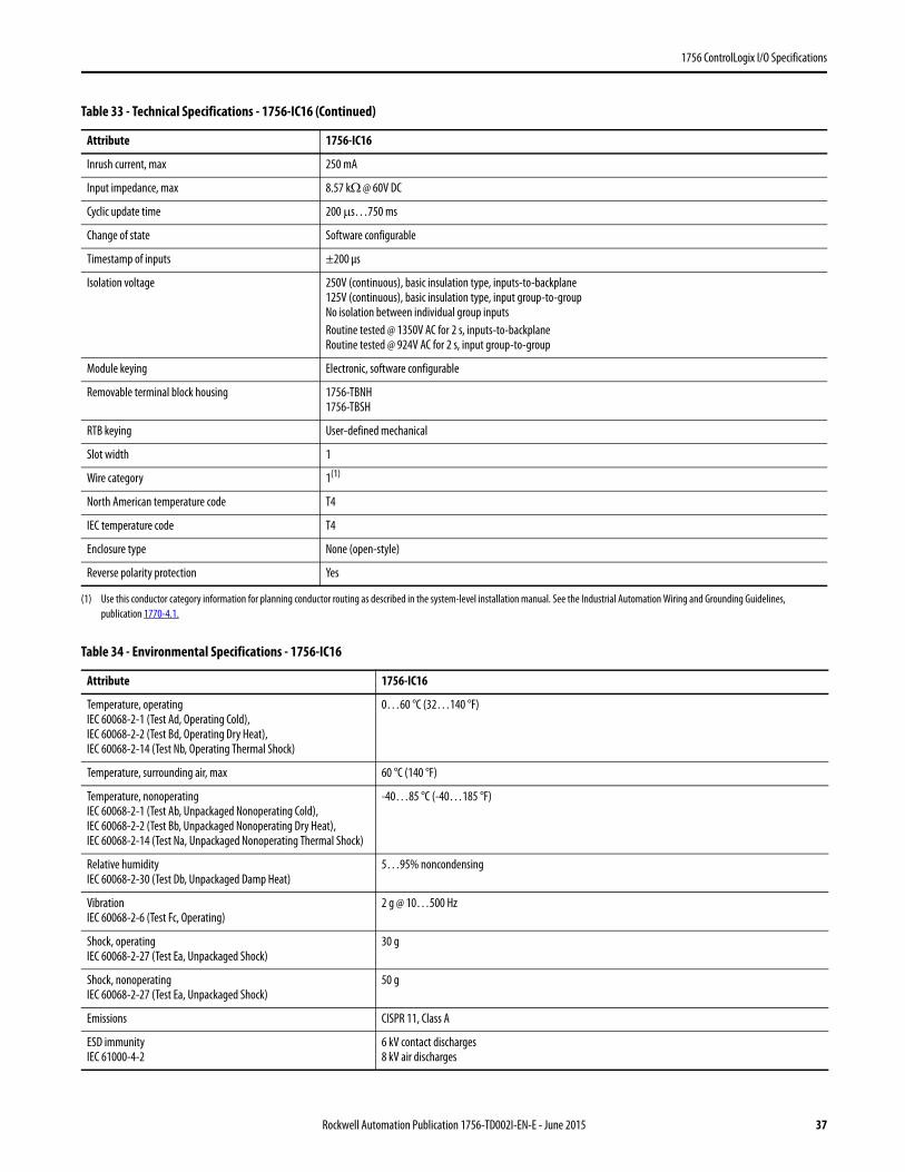
Table 33 - Technical Specifications - 1756-IC16
Attribute 1756-IC16
Inputs 16 (8 points/group)
Voltage category 48V DC sink
Operating voltage range 30…55V DC @ 60 °C (140 °F)30…60V DC @ 55 °C (131 °F)
Input voltage, nom 48V DC
Input delay time (screw to backplane)Off to On
On to Off
Hardware delay: 1 ms max + filter timeUser-selectable filter time: 0, 1, or 2 msHardware delay: 4 ms max + filter timeUser-selectable filter time: 0, 1, 2, 9, or 18 ms
Current draw @ 5.1V 100 mA
Current draw @ 24V 3 mA
Total backplane power 0.58 W
Power dissipation, max 5.2 W @ 60 °C (140 °F)
Thermal dissipation 17.73 BTU/hr
Off-state voltage, max 10V
Off-state current, max 1.5 mA
On-state current, min 2 mA @ 30V DC
On-state current, max 7 mA @ 60V DC
12
34
56
78
910
1112
1314
1516
1718
1920
+–Daisy Chain to Other RTBs
Group 0Group 0
Group 1Group 1
IN-1
IN-3
IN-5
IN-7
GND-0
IN-9
IN-11
IN-13
IN-15
GND-1
IN-0
IN-2
IN-4
IN-6
GND-0
IN-8
IN-10
IN-11
IN-14
GND-1
DC COM
Simplified Schematic
GND-0
IN-0
ControlLogix Backplane Interface
Display
GND
+5V
DC INPUT
ST 0 1 2 3 4 5 6 7
ST 8 9 10 11 12 13 14 15
OK
1756-IC16
36 Rockwell Automation Publication 1756-TD002I-EN-E - June 2015
1756 ControlLogix I/O Specifications
Inrush current, max 250 mA
Input impedance, max 8.57 kΩ @ 60V DC
Cyclic update time 200 μs…750 ms
Change of state Software configurable
Timestamp of inputs ±200 μs
Isolation voltage 250V (continuous), basic insulation type, inputs-to-backplane125V (continuous), basic insulation type, input group-to-groupNo isolation between individual group inputsRoutine tested @ 1350V AC for 2 s, inputs-to-backplaneRoutine tested @ 924V AC for 2 s, input group-to-group
Module keying Electronic, software configurable
Removable terminal block housing 1756-TBNH1756-TBSH
RTB keying User-defined mechanical
Slot width 1
Wire category 1(1)
North American temperature code T4
IEC temperature code T4
Enclosure type None (open-style)
Reverse polarity protection Yes
(1) Use this conductor category information for planning conductor routing as described in the system-level installation manual. See the Industrial Automation Wiring and Grounding Guidelines, publication 1770-4.1.
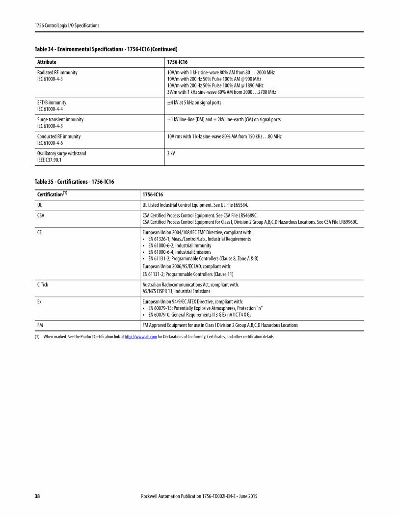
Table 34 - Environmental Specifications - 1756-IC16
Attribute 1756-IC16
Temperature, operatingIEC 60068-2-1 (Test Ad, Operating Cold),IEC 60068-2-2 (Test Bd, Operating Dry Heat),IEC 60068-2-14 (Test Nb, Operating Thermal Shock)
0…60 °C (32…140 °F)
Temperature, surrounding air, max 60 °C (140 °F)
Temperature, nonoperatingIEC 60068-2-1 (Test Ab, Unpackaged Nonoperating Cold),IEC 60068-2-2 (Test Bb, Unpackaged Nonoperating Dry Heat),IEC 60068-2-14 (Test Na, Unpackaged Nonoperating Thermal Shock)
-40…85 °C (-40…185 °F)
Relative humidityIEC 60068-2-30 (Test Db, Unpackaged Damp Heat)
5…95% noncondensing
VibrationIEC 60068-2-6 (Test Fc, Operating)
2 g @ 10…500 Hz
Shock, operatingIEC 60068-2-27 (Test Ea, Unpackaged Shock)
30 g
Shock, nonoperatingIEC 60068-2-27 (Test Ea, Unpackaged Shock)
50 g
Emissions CISPR 11, Class A
ESD immunityIEC 61000-4-2
6 kV contact discharges8 kV air discharges
Table 33 - Technical Specifications - 1756-IC16 (Continued)
Attribute 1756-IC16
Rockwell Automation Publication 1756-TD002I-EN-E - June 2015 37
1756 ControlLogix I/O Specifications
Radiated RF immunityIEC 61000-4-3
10V/m with 1 kHz sine-wave 80% AM from 80… 2000 MHz10V/m with 200 Hz 50% Pulse 100% AM @ 900 MHz10V/m with 200 Hz 50% Pulse 100% AM @ 1890 MHz3V/m with 1 kHz sine-wave 80% AM from 2000…2700 MHz
EFT/B immunityIEC 61000-4-4
±4 kV at 5 kHz on signal ports
Surge transient immunityIEC 61000-4-5
±1 kV line-line (DM) and ± 2kV line-earth (CM) on signal ports
Conducted RF immunityIEC 61000-4-6
10V rms with 1 kHz sine-wave 80% AM from 150 kHz…80 MHz
Oscillatory surge withstandIEEE C37.90.1
3 kV
Table 35 - Certifications - 1756-IC16
Certification(1)
(1) When marked. See the Product Certification link at http://www.ab.com for Declarations of Conformity, Certificates, and other certification details.
1756-IC16
UL UL Listed Industrial Control Equipment. See UL File E65584.
CSA CSA Certified Process Control Equipment. See CSA File LR54689C.CSA Certified Process Control Equipment for Class I, Division 2 Group A,B,C,D Hazardous Locations. See CSA File LR69960C.
CE European Union 2004/108/IEC EMC Directive, compliant with:• EN 61326-1; Meas./Control/Lab., Industrial Requirements• EN 61000-6-2; Industrial Immunity• EN 61000-6-4; Industrial Emissions• EN 61131-2; Programmable Controllers (Clause 8, Zone A & B)European Union 2006/95/EC LVD, compliant with:EN 61131-2; Programmable Controllers (Clause 11)
C-Tick Australian Radiocommunications Act, compliant with:AS/NZS CISPR 11; Industrial Emissions
Ex European Union 94/9/EC ATEX Directive, compliant with:• EN 60079-15; Potentially Explosive Atmospheres, Protection "n"• EN 60079-0; General Requirements II 3 G Ex nA IIC T4 X Gc
FM FM Approved Equipment for use in Class I Division 2 Group A,B,C,D Hazardous Locations
Table 34 - Environmental Specifications - 1756-IC16 (Continued)
Attribute 1756-IC16
38 Rockwell Automation Publication 1756-TD002I-EN-E - June 2015
1756 ControlLogix I/O Specifications
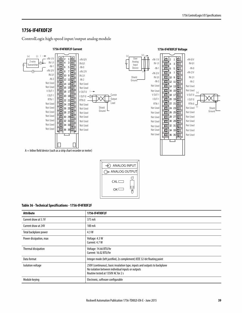
1756-IF4FXOF2FControlLogix high-speed input/output analog module
Table 36 - Technical Specifications - 1756-IF4FXOF2F
Attribute 1756-IF4FXOF2F
Current draw at 5.1V 375 mA
Current draw at 24V 100 mA
Total backplane power 4.3 W
Power dissipation, max Voltage: 4.3 WCurrent: 4.7 W
Thermal dissipation Voltage: 14.66 BTU/hrCurrent: 16.02 BTU/hr
Data format Integer mode (left justified, 2s complement) IEEE 32-bit floating point
Isolation voltage 250V (continuous), basic insulation type, inputs and outputs to backplaneNo isolation between individual inputs or outputsRoutine tested at 1350V AC for 2 s
Module keying Electronic, software configurable
+IN-1/VIN-1/I-IN-1
+IN-3/V
V OUT-1
IN-3/I-IN-3
Not UsedNot Used
I OUT-1RTN-1
Not Used
+IN-0/VIN-0/I-IN-0
+IN-2/VIN-2/I-IN-2
2-wire Transmitter
A
A
A
(+) (-) i
i
Shield Ground
CurrenOutput Load
Not Used
Not UsedNot Used
Not Used
Not Used
Not Used
V OUT-0
Not UsedNot Used
I OUT-0
Not UsedNot Used
Not UsedNot Used
Not Used
Not Used
Not Used
RTN-0
24
6
81012
141618
20
22242628
303234
36
13
5
7911
131517
19
21232527
293133
35
User Analog Input
Device
(+)
(-)
Shield Ground
(+)
(+)
(-)
Shield Ground
+IN-1/VIN-1/I
-IN-1
+IN-3/V
V OUT-1
IN-3/I-IN-3
Not Used
Not Used
I OUT-1
RTN-1
Not Used
+IN-0/VIN-0/I
-IN-0
+IN-2/V
IN-2/I
-IN-2
Not Used
Not Used
Not Used
Not UsedNot Used
Not Used
V OUT-0
Not Used
Not Used
I OUT-0
Not Used
Not Used
Not Used
Not Used
Not Used
Not Used
Not Used
RTN-0
2
4
6
8
10
12
14
16
18
20
22
24
26
28
30
32
34
36
1
3
5
7
9
11
13
15
17
19
21
23
25
27
29
31
33
35
A = Inline field device (such as a strip chart recorder or meter)
ANALOG INPUT
ANALOG OUTPUT
CAL
OK
1756-IF4FXOF2F Current 1756-IF4FXOF2F Voltage
Rockwell Automation Publication 1756-TD002I-EN-E - June 2015 39
1756 ControlLogix I/O Specifications
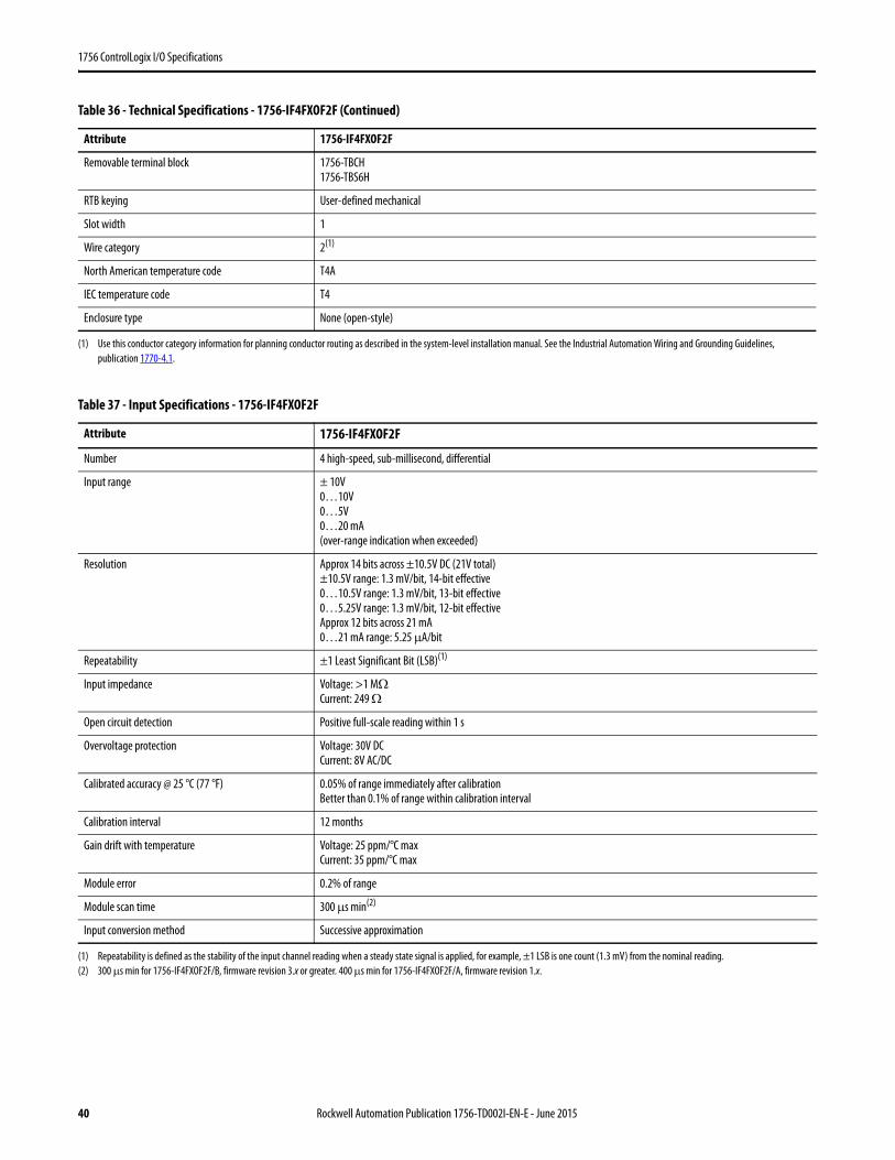
Removable terminal block 1756-TBCH1756-TBS6H
RTB keying User-defined mechanical
Slot width 1
Wire category 2(1)
North American temperature code T4A
IEC temperature code T4
Enclosure type None (open-style)
(1) Use this conductor category information for planning conductor routing as described in the system-level installation manual. See the Industrial Automation Wiring and Grounding Guidelines, publication 1770-4.1.
Table 37 - Input Specifications - 1756-IF4FXOF2F
Attribute 1756-IF4FXOF2F
Number 4 high-speed, sub-millisecond, differential
Input range ± 10V0…10V0…5V0…20 mA (over-range indication when exceeded)
Resolution Approx 14 bits across ±10.5V DC (21V total)±10.5V range: 1.3 mV/bit, 14-bit effective0…10.5V range: 1.3 mV/bit, 13-bit effective0…5.25V range: 1.3 mV/bit, 12-bit effectiveApprox 12 bits across 21 mA0…21 mA range: 5.25 μA/bit
Repeatability ±1 Least Significant Bit (LSB)(1)
(1) Repeatability is defined as the stability of the input channel reading when a steady state signal is applied, for example, ±1 LSB is one count (1.3 mV) from the nominal reading.
Input impedance Voltage: >1 MΩCurrent: 249 Ω
Open circuit detection Positive full-scale reading within 1 s
Overvoltage protection Voltage: 30V DCCurrent: 8V AC/DC
Calibrated accuracy @ 25 °C (77 °F) 0.05% of range immediately after calibrationBetter than 0.1% of range within calibration interval
Calibration interval 12 months
Gain drift with temperature Voltage: 25 ppm/°C maxCurrent: 35 ppm/°C max
Module error 0.2% of range
Module scan time 300 μs min(2)
(2) 300 µs min for 1756-IF4FXOF2F/B, firmware revision 3.x or greater. 400 µs min for 1756-IF4FXOF2F/A, firmware revision 1.x.
Input conversion method Successive approximation
Table 36 - Technical Specifications - 1756-IF4FXOF2F (Continued)
Attribute 1756-IF4FXOF2F
40 Rockwell Automation Publication 1756-TD002I-EN-E - June 2015

1756 ControlLogix I/O Specifications
Table 38 - Output Specifications - 1756-IF4FXOF2F
Attribute 1756-IF4FXOF2F
Number 2 high-speed voltage or current
Output range ± 10V0…20 mA
Resolution 13 bits across 21 mA = 2.8 μA/bit14 bits across 21.8V = 1.3 mV/bit
Open circuit detection Current output only (Output must be set to >0.1 mA)
Overvoltage protection 24V DC
Short circuit protection Electronically current limited to 21 mA or less
Drive capability Voltage: >2000 ΩCurrent: 0…750 Ω
Output settling time < 2 ms to 95% of final value with resistive loads
Calibrated accuracy @ 25 °C (77 °F) 0.05% of range immediately after calibrationBetter than 0.1% of range within calibration interval
Calibration interval 12 months
Offset drift 50 μV/° C1 μA/° C
Gain drift with temperature Voltage: 25 ppm/°C maxCurrent: 50 ppm/°C max
Module error Voltage: 0.2% of rangeCurrent: 0.3% of range
Update period for all channels (RPI), min 1 ms
Output conversion method R-Ladder DAC, monotonicity with no missing codes
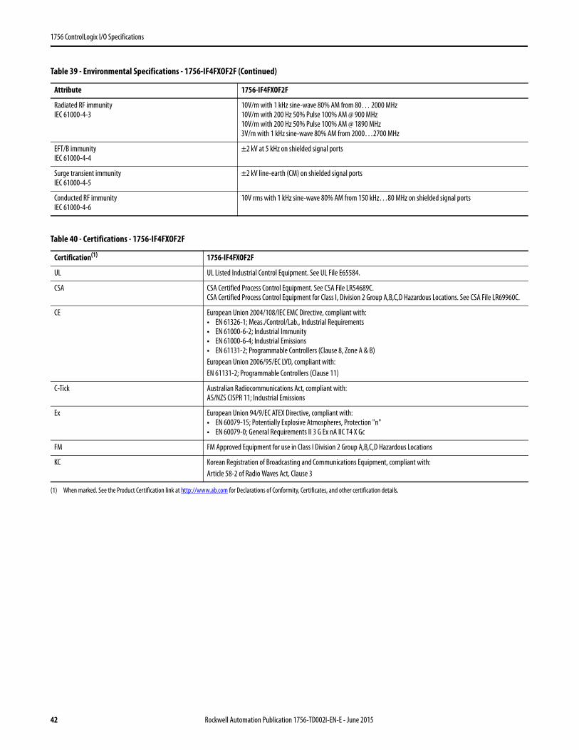
Table 39 - Environmental Specifications - 1756-IF4FXOF2F
Attribute 1756-IF4FXOF2F
Temperature, operatingIEC 60068-2-1 (Test Ad, Operating Cold),IEC 60068-2-2 (Test Bd, Operating Dry Heat),IEC 60068-2-14 (Test Nb, Operating Thermal Shock)
0…60 °C (32…140 °F)
Temperature, surrounding air, max 60 °C (140 °F)
Temperature, nonoperatingIEC 60068-2-1 (Test Ab, Unpackaged Nonoperating Cold),IEC 60068-2-2 (Test Bb, Unpackaged Nonoperating Dry Heat),IEC 60068-2-14 (Test Na, Unpackaged Nonoperating Thermal Shock)
-40…85 °C (-40…185 °F)
Relative humidityIEC 60068-2-30 (Test Db, Unpackaged Damp Heat)
5…95% noncondensing
VibrationIEC 60068-2-6 (Test Fc, Operating)
2 g @ 10…500 Hz
Shock, operatingIEC 60068-2-27 (Test Ea, Unpackaged Shock)
30 g
Shock, nonoperatingIEC 60068-2-27 (Test Ea, Unpackaged Shock)
50 g
Emissions CISPR 11, Class A
ESD immunityIEC 61000-4-2
6 kV contact discharges8 kV air discharges
Rockwell Automation Publication 1756-TD002I-EN-E - June 2015 41
1756 ControlLogix I/O Specifications
Radiated RF immunityIEC 61000-4-3
10V/m with 1 kHz sine-wave 80% AM from 80… 2000 MHz10V/m with 200 Hz 50% Pulse 100% AM @ 900 MHz10V/m with 200 Hz 50% Pulse 100% AM @ 1890 MHz3V/m with 1 kHz sine-wave 80% AM from 2000…2700 MHz
EFT/B immunityIEC 61000-4-4
±2 kV at 5 kHz on shielded signal ports
Surge transient immunityIEC 61000-4-5
±2 kV line-earth (CM) on shielded signal ports
Conducted RF immunityIEC 61000-4-6
10V rms with 1 kHz sine-wave 80% AM from 150 kHz…80 MHz on shielded signal ports
Table 40 - Certifications - 1756-IF4FXOF2F
Certification(1)
(1) When marked. See the Product Certification link at http://www.ab.com for Declarations of Conformity, Certificates, and other certification details.
1756-IF4FXOF2F
UL UL Listed Industrial Control Equipment. See UL File E65584.
CSA CSA Certified Process Control Equipment. See CSA File LR54689C.CSA Certified Process Control Equipment for Class I, Division 2 Group A,B,C,D Hazardous Locations. See CSA File LR69960C.
CE European Union 2004/108/IEC EMC Directive, compliant with:• EN 61326-1; Meas./Control/Lab., Industrial Requirements• EN 61000-6-2; Industrial Immunity• EN 61000-6-4; Industrial Emissions• EN 61131-2; Programmable Controllers (Clause 8, Zone A & B)European Union 2006/95/EC LVD, compliant with:EN 61131-2; Programmable Controllers (Clause 11)
C-Tick Australian Radiocommunications Act, compliant with:AS/NZS CISPR 11; Industrial Emissions
Ex European Union 94/9/EC ATEX Directive, compliant with:• EN 60079-15; Potentially Explosive Atmospheres, Protection "n"• EN 60079-0; General Requirements II 3 G Ex nA IIC T4 X Gc
FM FM Approved Equipment for use in Class I Division 2 Group A,B,C,D Hazardous Locations
KC Korean Registration of Broadcasting and Communications Equipment, compliant with:Article 58-2 of Radio Waves Act, Clause 3
Table 39 - Environmental Specifications - 1756-IF4FXOF2F (Continued)
Attribute 1756-IF4FXOF2F
42 Rockwell Automation Publication 1756-TD002I-EN-E - June 2015
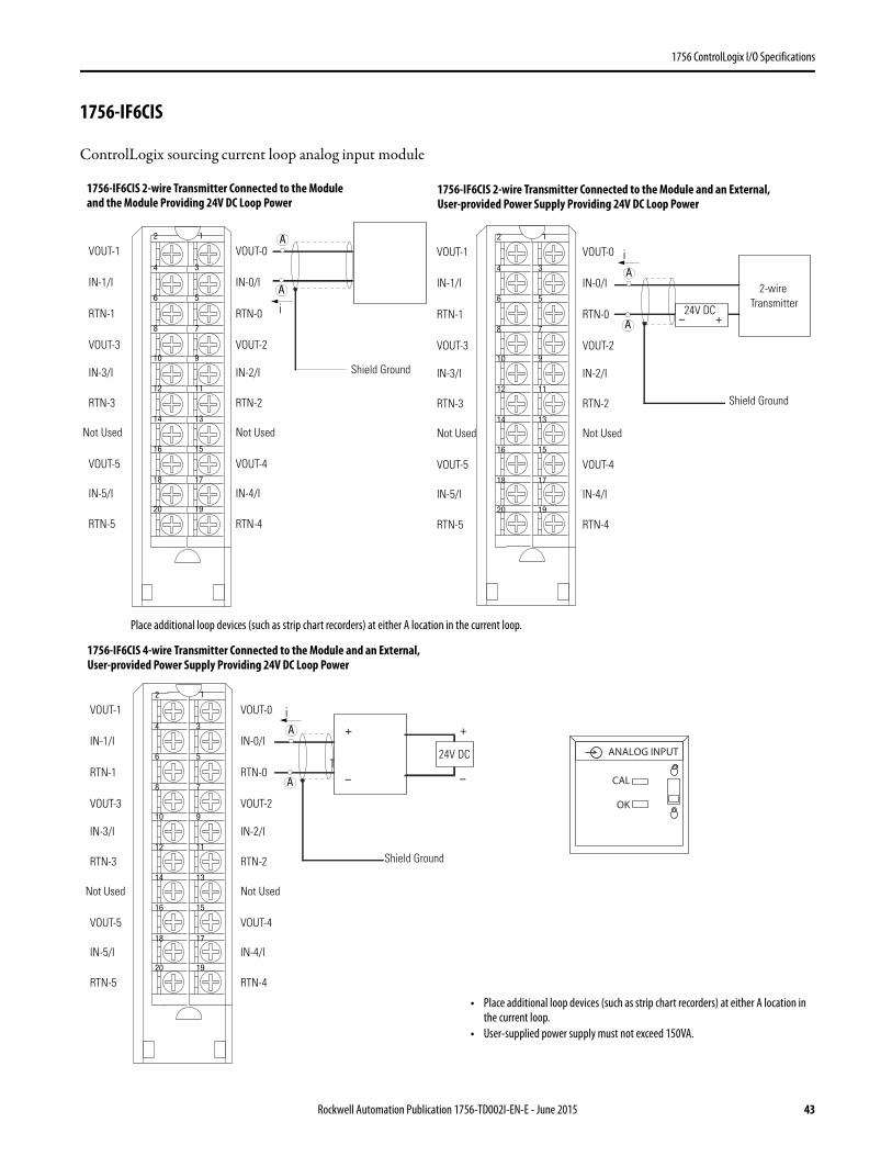
1756 ControlLogix I/O Specifications
1756-IF6CIS
ControlLogix sourcing current loop analog input module
12
34
56
78
910
1112
1314
1516
1718
1920
VOUT-1
IN-1/I
RTN-1
VOUT-3
IN-3/I
RTN-3
Not Used
VOUT-5
IN-5/I
RTN-5
VOUT-0
IN-0/I
RTN-0
VOUT-2
IN-2/I
RTN-2
Not Used
VOUT-4
IN-4/I
RTN-4
2-wireTransmitter
Shield Ground
+–
iA
A24V DC
12
34
56
78
910
1112
1314
1516
1718
1920
VOUT-1
IN-1/I
RTN-1
VOUT-3
IN-3/I
RTN-3
Not Used
VOUT-5
IN-5/I
RTN-5
VOUT-0
IN-0/I
RTN-0
VOUT-2
IN-2/I
RTN-2
Not Used
VOUT-4
IN-4/I
RTN-4
Shield Ground
A
iA
Place additional loop devices (such as strip chart recorders) at either A location in the current loop.
1756-IF6CIS 2-wire Transmitter Connected to the Module and an External, User-provided Power Supply Providing 24V DC Loop Power
1756-IF6CIS 2-wire Transmitter Connected to the Module and the Module Providing 24V DC Loop Power
12
34
56
78
910
1112
1314
1516
1718
1920
VOUT-1
IN-1/I
RTN-1
VOUT-3
IN-3/I
RTN-3
Not Used
VOUT-5
IN-5/I
RTN-5
VOUT-0
IN-0/I
RTN-0
VOUT-2
IN-2/I
RTN-2
Not Used
VOUT-4
IN-4/I
RTN-4
4-wireTransmitter
Shield Ground
+
–
+
–
iA
A
24V DC
• Place additional loop devices (such as strip chart recorders) at either A location in the current loop.
• User-supplied power supply must not exceed 150VA.
ANALOG INPUT
CAL
OK
1756-IF6CIS 4-wire Transmitter Connected to the Module and an External, User-provided Power Supply Providing 24V DC Loop Power
Rockwell Automation Publication 1756-TD002I-EN-E - June 2015 43
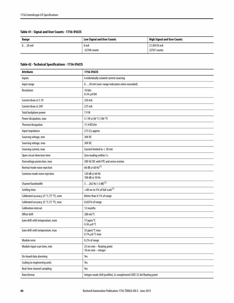
1756 ControlLogix I/O Specifications
Table 41 - Signal and User Counts - 1756-IF6CIS
Range Low Signal and User Counts High Signal and User Counts
0…20 mA 0 mA-32768 counts
21.09376 mA32767 counts
Table 42 - Technical Specifications - 1756-IF6CIS
Attribute 1756-IF6CIS
Inputs 6 individually isolated current sourcing
Input range 0…20 mA (over-range indication when exceeded)
Resolution 16 bits0.34 μA/bit
Current draw @ 5.1V 250 mA
Current draw @ 24V 275 mA
Total backplane power 7.9 W
Power dissipation, max 5.1 W @ 60 °C (140 °F)
Thermal dissipation 17.4 BTU/hr
Input impedance 215 Ω, approx
Sourcing voltage, min 20V DC
Sourcing voltage, max 30V DC
Sourcing current, max Current limited to < 30 mA
Open circuit detection time Zero reading within 5 s
Overvoltage protection, max 30V AC/DC with PTC and sense resistor
Normal mode noise rejection 60 dB @ 60 Hz(1)
Common mode noise rejection 120 dB @ 60 Hz100 dB @ 50 Hz
Channel bandwidth 3…262 Hz (-3 dB)(1)
Settling time <80 ms to 5% of full scale(1)
Calibrated accuracy 25 °C (77 °F), nom Better than 0.1% of range
Calibrated accuracy 25 °C (77 °F), max 0.025% of range
Calibration interval 12 months
Offset drift 200 nA/°C
Gain drift with temperature, nom 17 ppm/°C0.36 μA/°C
Gain drift with temperature, max 35 ppm/°C max0.74 μA/°C max
Module error 0.2% of range
Module input scan time, min 25 ms min – floating point10 ms min – integer
On-board data alarming Yes
Scaling to engineering units Yes
Real-time channel sampling Yes
Data format Integer mode (left justified, 2s complement) IEEE 32-bit floating point
44 Rockwell Automation Publication 1756-TD002I-EN-E - June 2015
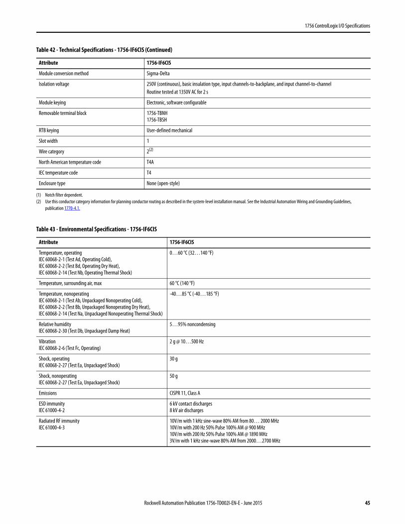
1756 ControlLogix I/O Specifications
Module conversion method Sigma-Delta
Isolation voltage 250V (continuous), basic insulation type, input channels-to-backplane, and input channel-to-channelRoutine tested at 1350V AC for 2 s
Module keying Electronic, software configurable
Removable terminal block 1756-TBNH1756-TBSH
RTB keying User-defined mechanical
Slot width 1
Wire category 2(2)
North American temperature code T4A
IEC temperature code T4
Enclosure type None (open-style)
(1) Notch filter dependent.(2) Use this conductor category information for planning conductor routing as described in the system-level installation manual. See the Industrial Automation Wiring and Grounding Guidelines,
publication 1770-4.1.
Table 43 - Environmental Specifications - 1756-IF6CIS
Attribute 1756-IF6CIS
Temperature, operatingIEC 60068-2-1 (Test Ad, Operating Cold),IEC 60068-2-2 (Test Bd, Operating Dry Heat),IEC 60068-2-14 (Test Nb, Operating Thermal Shock)
0…60 °C (32…140 °F)
Temperature, surrounding air, max 60 °C (140 °F)
Temperature, nonoperatingIEC 60068-2-1 (Test Ab, Unpackaged Nonoperating Cold),IEC 60068-2-2 (Test Bb, Unpackaged Nonoperating Dry Heat),IEC 60068-2-14 (Test Na, Unpackaged Nonoperating Thermal Shock)
-40…85 °C (-40…185 °F)
Relative humidityIEC 60068-2-30 (Test Db, Unpackaged Damp Heat)
5…95% noncondensing
VibrationIEC 60068-2-6 (Test Fc, Operating)
2 g @ 10…500 Hz
Shock, operatingIEC 60068-2-27 (Test Ea, Unpackaged Shock)
30 g
Shock, nonoperatingIEC 60068-2-27 (Test Ea, Unpackaged Shock)
50 g
Emissions CISPR 11, Class A
ESD immunityIEC 61000-4-2
6 kV contact discharges8 kV air discharges
Radiated RF immunityIEC 61000-4-3
10V/m with 1 kHz sine-wave 80% AM from 80… 2000 MHz10V/m with 200 Hz 50% Pulse 100% AM @ 900 MHz10V/m with 200 Hz 50% Pulse 100% AM @ 1890 MHz3V/m with 1 kHz sine-wave 80% AM from 2000…2700 MHz
Table 42 - Technical Specifications - 1756-IF6CIS (Continued)
Attribute 1756-IF6CIS
Rockwell Automation Publication 1756-TD002I-EN-E - June 2015 45
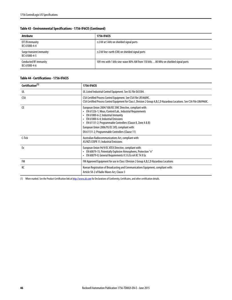
1756 ControlLogix I/O Specifications
EFT/B immunityIEC 61000-4-4
±2 kV at 5 kHz on shielded signal ports
Surge transient immunityIEC 61000-4-5
±2 kV line-earth (CM) on shielded signal ports
Conducted RF immunityIEC 61000-4-6
10V rms with 1 kHz sine-wave 80% AM from 150 kHz…80 MHz on shielded signal ports
Table 44 - Certifications - 1756-IF6CIS
Certification(1)
(1) When marked. See the Product Certification link at http://www.ab.com for Declarations of Conformity, Certificates, and other certification details.
1756-IF6CIS
UL UL Listed Industrial Control Equipment. See UL File E65584.
CSA CSA Certified Process Control Equipment. See CSA File LR54689C.CSA Certified Process Control Equipment for Class I, Division 2 Group A,B,C,D Hazardous Locations. See CSA File LR69960C.
CE European Union 2004/108/IEC EMC Directive, compliant with:• EN 61326-1; Meas./Control/Lab., Industrial Requirements• EN 61000-6-2; Industrial Immunity• EN 61000-6-4; Industrial Emissions• EN 61131-2; Programmable Controllers (Clause 8, Zone A & B)European Union 2006/95/EC LVD, compliant with:EN 61131-2; Programmable Controllers (Clause 11)
C-Tick Australian Radiocommunications Act, compliant with:AS/NZS CISPR 11; Industrial Emissions
Ex European Union 94/9/EC ATEX Directive, compliant with:• EN 60079-15; Potentially Explosive Atmospheres, Protection "n"• EN 60079-0; General Requirements II 3 G Ex nA IIC T4 X Gc
FM FM Approved Equipment for use in Class I Division 2 Group A,B,C,D Hazardous Locations
KC Korean Registration of Broadcasting and Communications Equipment, compliant with:Article 58-2 of Radio Waves Act, Clause 3
Table 43 - Environmental Specifications - 1756-IF6CIS (Continued)
Attribute 1756-IF6CIS
46 Rockwell Automation Publication 1756-TD002I-EN-E - June 2015
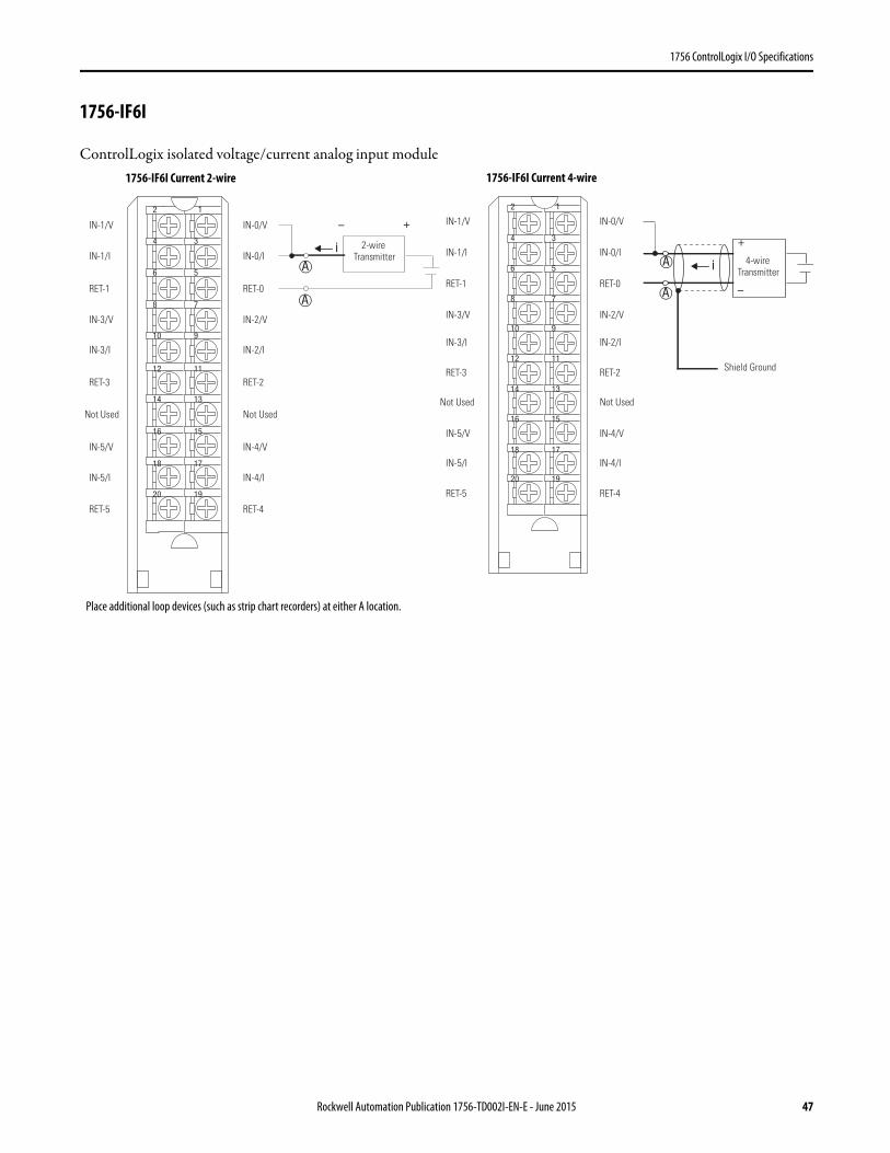
1756 ControlLogix I/O Specifications
1756-IF6I
ControlLogix isolated voltage/current analog input module
12
34
56
78
910
1112
1314
1516
1718
1920
+–
iA
A
2-wire Transmitter
IN-1/V
IN-1/I
RET-1
IN-3/V
IN-3/I
RET-3
Not Used
IN-5/V
IN-5/I
RET-5
IN-0/V
IN-0/I
RET-0
IN-2/V
IN-2/I
RET-2
Not Used
IN-4/V
IN-4/I
RET-4
+
–
12
34
56
78
910
1112
1314
1516
1718
1920
iA
A
IN-1/V
IN-1/I
RET-1
IN-3/V
IN-3/I
RET-3
Not Used
IN-5/V
IN-5/I
RET-5
IN-0/V
IN-0/I
RET-0
IN-2/V
IN-2/I
RET-2
Not Used
IN-4/V
IN-4/I
RET-4
Shield Ground
4-wire Transmitter
Place additional loop devices (such as strip chart recorders) at either A location.
1756-IF6I Current 2-wire 1756-IF6I Current 4-wire
Rockwell Automation Publication 1756-TD002I-EN-E - June 2015 47
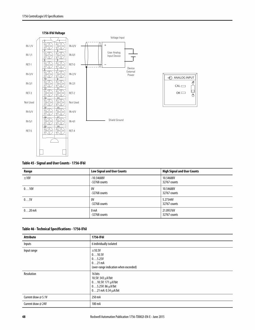
1756 ControlLogix I/O Specifications
Table 45 - Signal and User Counts - 1756-IF6I
Range Low Signal and User Counts High Signal and User Counts
±10V -10.54688V-32768 counts
10.54688V32767 counts
0…10V 0V-32768 counts
10.54688V32767 counts
0…5V 0V-32768 counts
5.27344V32767 counts
0…20 mA 0 mA-32768 counts
21.09376V32767 counts
Table 46 - Technical Specifications - 1756-IF6I
Attribute 1756-IF6I
Inputs 6 individually isolated
Input range ±10.5V0…10.5V0…5.25V0…21 mA (over-range indication when exceeded)
Resolution 16 bits10.5V: 343 μV/bit0…10.5V: 171 μV/bit0…5.25V: 86 μV/bit0…21 mA: 0.34 μA/bit
Current draw @ 5.1V 250 mA
Current draw @ 24V 100 mA
+
–
12
34
56
78
910
1112
1314
1516
1718
1920
Device External Power
Voltage Input
Shield Ground
User Analog Input Device
IN-1/V
IN-1/I
RET-1
IN-3/V
IN-3/I
RET-3
Not Used
IN-5/V
IN-5/I
RET-5
IN-0/V
IN-0/I
RET-0
IN-2/V
IN-2/I
RET-2
Not Used
IN-4/V
IN-4/I
RET-4
ANALOG INPUT
CAL
OK
1756-IF6I Voltage
48 Rockwell Automation Publication 1756-TD002I-EN-E - June 2015
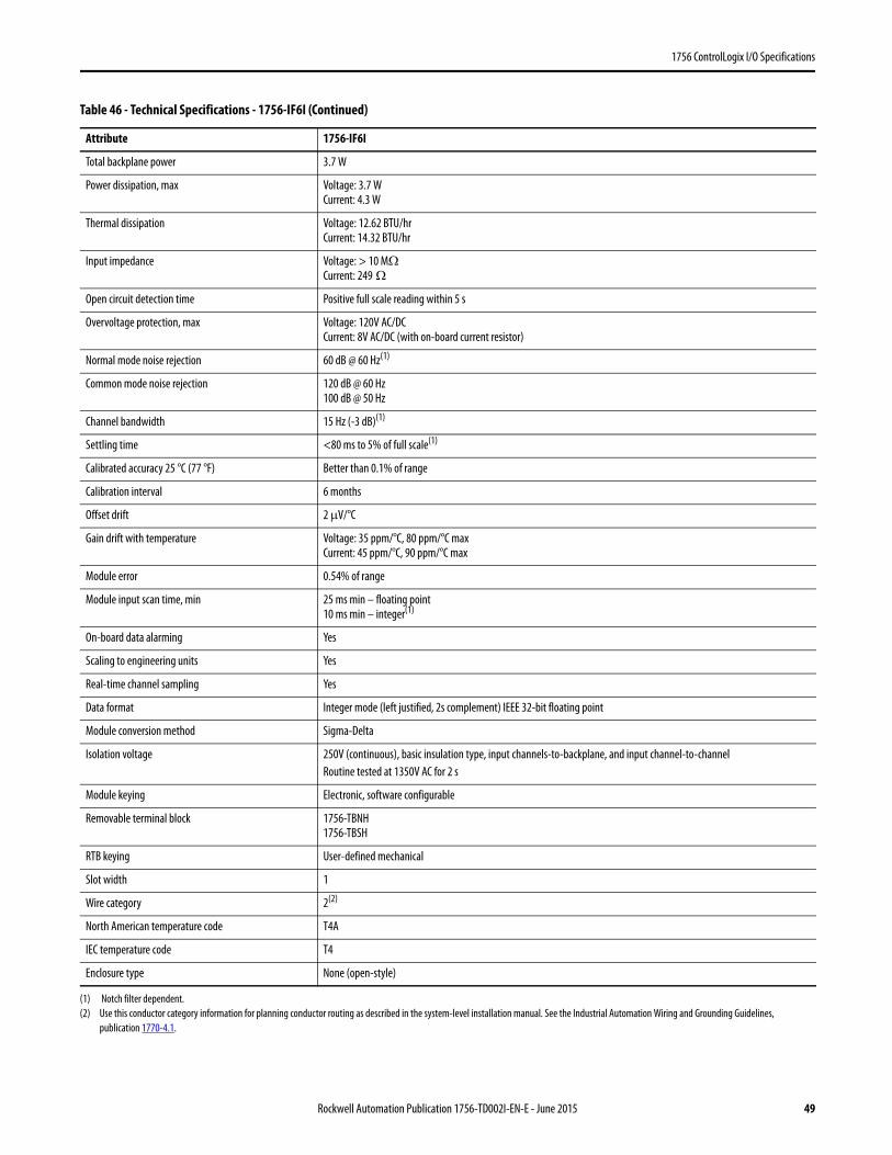
1756 ControlLogix I/O Specifications
Total backplane power 3.7 W
Power dissipation, max Voltage: 3.7 WCurrent: 4.3 W
Thermal dissipation Voltage: 12.62 BTU/hrCurrent: 14.32 BTU/hr
Input impedance Voltage: > 10 MΩCurrent: 249 Ω
Open circuit detection time Positive full scale reading within 5 s
Overvoltage protection, max Voltage: 120V AC/DCCurrent: 8V AC/DC (with on-board current resistor)
Normal mode noise rejection 60 dB @ 60 Hz(1)
Common mode noise rejection 120 dB @ 60 Hz100 dB @ 50 Hz
Channel bandwidth 15 Hz (-3 dB)(1)
Settling time <80 ms to 5% of full scale(1)
Calibrated accuracy 25 °C (77 °F) Better than 0.1% of range
Calibration interval 6 months
Offset drift 2 μV/°C
Gain drift with temperature Voltage: 35 ppm/°C, 80 ppm/°C maxCurrent: 45 ppm/°C, 90 ppm/°C max
Module error 0.54% of range
Module input scan time, min 25 ms min – floating point10 ms min – integer(1)
On-board data alarming Yes
Scaling to engineering units Yes
Real-time channel sampling Yes
Data format Integer mode (left justified, 2s complement) IEEE 32-bit floating point
Module conversion method Sigma-Delta
Isolation voltage 250V (continuous), basic insulation type, input channels-to-backplane, and input channel-to-channelRoutine tested at 1350V AC for 2 s
Module keying Electronic, software configurable
Removable terminal block 1756-TBNH1756-TBSH
RTB keying User-defined mechanical
Slot width 1
Wire category 2(2)
North American temperature code T4A
IEC temperature code T4
Enclosure type None (open-style)
(1) Notch filter dependent.(2) Use this conductor category information for planning conductor routing as described in the system-level installation manual. See the Industrial Automation Wiring and Grounding Guidelines,
publication 1770-4.1.
Table 46 - Technical Specifications - 1756-IF6I (Continued)
Attribute 1756-IF6I
Rockwell Automation Publication 1756-TD002I-EN-E - June 2015 49

1756 ControlLogix I/O Specifications
Table 47 - Environmental Specifications - 1756-IF6I
Attribute 1756-IF6I
Temperature, operatingIEC 60068-2-1 (Test Ad, Operating Cold),IEC 60068-2-2 (Test Bd, Operating Dry Heat),IEC 60068-2-14 (Test Nb, Operating Thermal Shock)
0…60 °C (32…140 °F)
Temperature, surrounding air, max 60 °C (140 °F)
Temperature, nonoperatingIEC 60068-2-1 (Test Ab, Unpackaged Nonoperating Cold),IEC 60068-2-2 (Test Bb, Unpackaged Nonoperating Dry Heat),IEC 60068-2-14 (Test Na, Unpackaged Nonoperating Thermal Shock)
-40…85 °C (-40…185 °F)
Relative humidityIEC 60068-2-30 (Test Db, Unpackaged Damp Heat)
5…95% noncondensing
VibrationIEC 60068-2-6 (Test Fc, Operating)
2 g @ 10…500 Hz
Shock, operatingIEC 60068-2-27 (Test Ea, Unpackaged Shock)
30 g
Shock, nonoperatingIEC 60068-2-27 (Test Ea, Unpackaged Shock)
50 g
Emissions CISPR 1, Class A
ESD immunityIEC 61000-4-2
6 kV contact discharges8 kV air discharges
Radiated RF immunityIEC 61000-4-3
10V/m with 1 kHz sine-wave 80% AM from 80…2000 MHz10V/m with 200 Hz 50% Pulse 100% AM @ 900 MHz10V/m with 200 Hz 50% Pulse 100% AM @ 1890 MHz3V/m with 1 kHz sine-wave 80% AM from 2000…2700 MHz
EFT/B immunityIEC 61000-4-4
±2 kV at 5 kHz on shielded signal ports
Surge transient immunityIEC 61000-4-5
±2 kV line-earth (CM) on shielded signal ports
Conducted RF immunityIEC 61000-4-6
10V rms with 1 kHz sine-wave 80% AM from 150 kHz…80 MHz on shielded signal ports
50 Rockwell Automation Publication 1756-TD002I-EN-E - June 2015
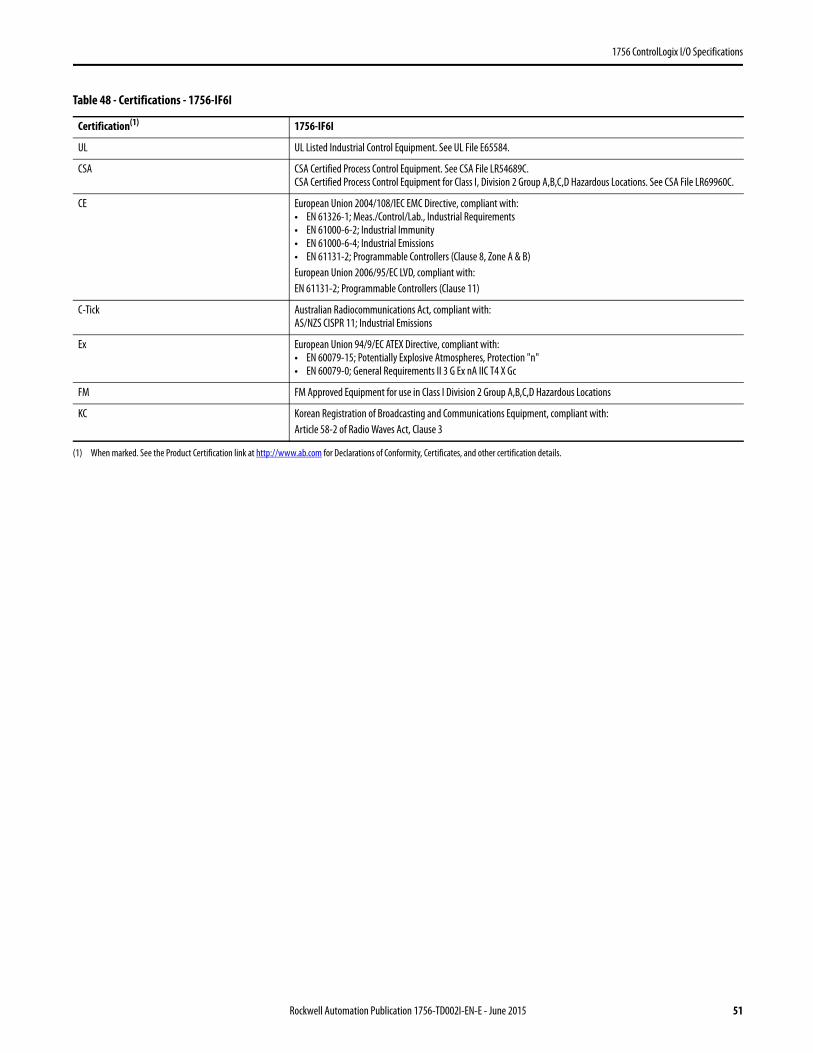
1756 ControlLogix I/O Specifications
Table 48 - Certifications - 1756-IF6I
Certification(1) 1756-IF6I
UL UL Listed Industrial Control Equipment. See UL File E65584.
CSA CSA Certified Process Control Equipment. See CSA File LR54689C.CSA Certified Process Control Equipment for Class I, Division 2 Group A,B,C,D Hazardous Locations. See CSA File LR69960C.
CE European Union 2004/108/IEC EMC Directive, compliant with:• EN 61326-1; Meas./Control/Lab., Industrial Requirements• EN 61000-6-2; Industrial Immunity• EN 61000-6-4; Industrial Emissions• EN 61131-2; Programmable Controllers (Clause 8, Zone A & B)European Union 2006/95/EC LVD, compliant with:EN 61131-2; Programmable Controllers (Clause 11)
C-Tick Australian Radiocommunications Act, compliant with:AS/NZS CISPR 11; Industrial Emissions
Ex European Union 94/9/EC ATEX Directive, compliant with:• EN 60079-15; Potentially Explosive Atmospheres, Protection "n"• EN 60079-0; General Requirements II 3 G Ex nA IIC T4 X Gc
FM FM Approved Equipment for use in Class I Division 2 Group A,B,C,D Hazardous Locations
KC Korean Registration of Broadcasting and Communications Equipment, compliant with:Article 58-2 of Radio Waves Act, Clause 3
(1) When marked. See the Product Certification link at http://www.ab.com for Declarations of Conformity, Certificates, and other certification details.
Rockwell Automation Publication 1756-TD002I-EN-E - June 2015 51
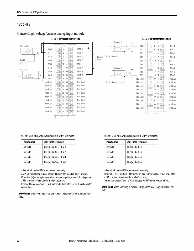
1756 ControlLogix I/O Specifications
1756-IF8
ControlLogix voltage/current analog input module
2
4
6
8
10
12
14
16
18
20
22
24
26
28
30
32
34
36
i
i
A
A
Shield Ground
Channel 0
Channel 3
Jumper Wires
2-wire Transmitter
IN-0
IN-1
IN-2
IN-3
IN-7
RTN
IN-4
IN-5
IN-6
Not Used
Not UsedNot Used
Not Used
Not Used
Not Used
Not Used
Not Used
Not Used
1
3
5
7
9
11
13
15
17
19
21
23
25
27
29
31
33
35
i RTN-0
i RTN-1
i RTN-2
i RTN-3
i RTN-7
RTN
i RTN-4
i RTN-5
i RTN-6
Not Used
Not UsedNot Used
Not Used
Not Used
Not Used
Not Used
Not Used
Not Used
12
34
56
78
910
1112
1314
1516
1718
1920
2122
2324
2526
2728
2930
3132
3334
3536
+
–
+
–
Shield Ground
Channel 0
Channel 3
IN-0
IN-1
IN-2
IN-3
IN-7
RTN
IN-4
IN-5
IN-6
Not Used
Not UsedNot Used
Not Used
Not Used
Not Used
Not Used
Not Used
Not Used
i RTN-0
i RTN-1
i RTN-2
i RTN-3
i RTN-7
RTN
i RTN-4
i RTN-5
i RTN-6
Not Used
Not UsedNot Used
Not Used
Not Used
Not Used
Not Used
Not Used
Not Used
Shield Ground
• Use this table when wiring your module in Differential mode.
• All terminals marked RTN are connected internally.• A 249 Ω current loop resistor is located between IN-x and i RTN-x terminals.• If multiple (+) or multiple (-) terminals are tied together, connect that tie point to
a RTN terminal to maintain the module’s accuracy.• Place additional loop devices (such as strip chart recorders) at the A location in the
current loop.
IMPORTANT: When operating in 2 channel, High Speed mode, only use channels 0 and 2.
This channel Uses these terminals
Channel 0 IN-0 (+), IN-1 (-), i RTN-0
Channel 1 IN-2 (+), IN-3 (-), i RTN-2
Channel 2 IN-4 (+), IN-5 (-), i RTN-4
Channel 3 IN-6 (+), IN-7 (-), i RTN-6
• Use this table when wiring your module in Differential mode.
• All terminals marked RTN are connected internally.• If multiple (+) or multiple (-) terminals are tied together, connect that tie point to
a RTN terminal to maintain the module’s accuracy.• Terminals marked RTN or i RTN are not used for differential voltage wiring.
IMPORTANT: When operating in 2 channel, High Speed mode, only use channels 0 and 2.
This channel Uses these terminals
Channel 0 IN-0 (+), IN-1 (-)
Channel 1 IN-2 (+), IN-3 (-)
Channel 2 IN-4 (+), IN-5 (-)
Channel 3 IN-6 (+), IN-7 (-)
1756-IF8 Differential Current 1756-IF8 Differential Voltage
52 Rockwell Automation Publication 1756-TD002I-EN-E - June 2015
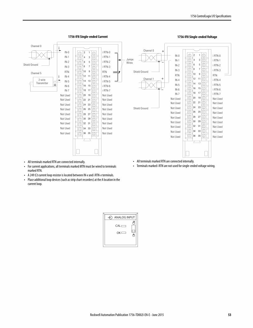
1756 ControlLogix I/O Specifications
12
34
56
78
910
1112
1314
1516
1718
1920
2122
2324
2526
2728
2930
3132
3334
3536
i
i
A
Shield Ground
Channel 0
Channel 5
Jumper Wires
2-wire Transmitter
IN-0
IN-1
IN-2
IN-3
IN-7
RTN
IN-4
IN-5
IN-6
Not Used
Not UsedNot Used
Not Used
Not Used
Not Used
Not Used
Not Used
Not Used
i RTN-0
i RTN-1
i RTN-2
i RTN-3
i RTN-7
RTN
i RTN-4
i RTN-5
i RTN-6
Not Used
Not UsedNot Used
Not Used
Not Used
Not Used
Not Used
Not Used
Not Used
12
34
56
78
910
1112
1314
1516
1718
1920
2122
2324
2526
2728
2930
3132
3334
3536
+
–
+
–
IN-0
IN-1
IN-2
IN-3
IN-7
RTN
IN-4
IN-5
IN-6
Not Used
Not UsedNot Used
Not Used
Not Used
Not Used
Not Used
Not Used
Not Used
i RTN-0
i RTN-1
i RTN-2
i RTN-3
i RTN-7
RTN
i RTN-4
i RTN-5
i RTN-6
Not Used
Not UsedNot Used
Not Used
Not Used
Not Used
Not Used
Not Used
Not Used
Shield Ground
Channel 0
Channel 1
Shield Ground
• All terminals marked RTN are connected internally.• For current applications, all terminals marked iRTN must be wired to terminals
marked RTN.• A 249 Ω current loop resistor is located between IN-x and i RTN-x terminals.• Place additional loop devices (such as strip chart recorders) at the A location in the
current loop.
• All terminals marked RTN are connected internally.• Terminals marked i RTN are not used for single-ended voltage wiring.
ANALOG INPUT
CAL
OK
1756-IF8 Single-ended Current 1756-IF8 Single-ended Voltage
Rockwell Automation Publication 1756-TD002I-EN-E - June 2015 53
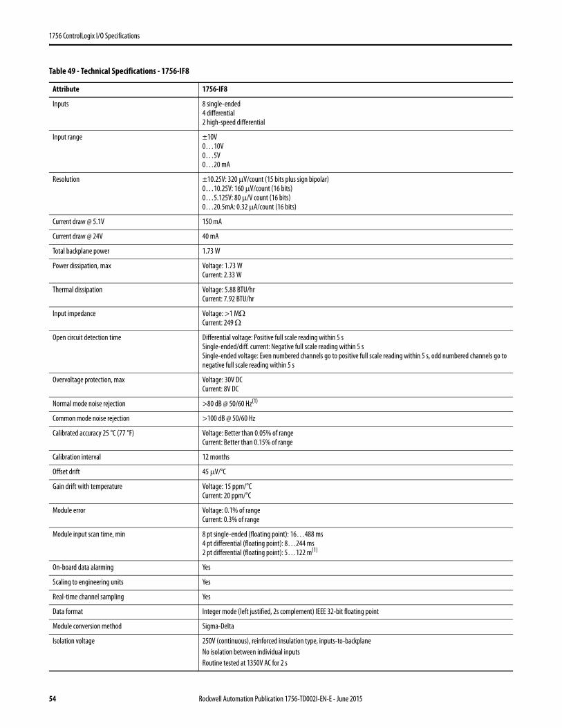
1756 ControlLogix I/O Specifications
Table 49 - Technical Specifications - 1756-IF8
Attribute 1756-IF8
Inputs 8 single-ended4 differential2 high-speed differential
Input range ±10V0…10V0…5V0…20 mA
Resolution ±10.25V: 320 μV/count (15 bits plus sign bipolar)0…10.25V: 160 μV/count (16 bits)0…5.125V: 80 μ/V count (16 bits)0…20.5mA: 0.32 μA/count (16 bits)
Current draw @ 5.1V 150 mA
Current draw @ 24V 40 mA
Total backplane power 1.73 W
Power dissipation, max Voltage: 1.73 WCurrent: 2.33 W
Thermal dissipation Voltage: 5.88 BTU/hrCurrent: 7.92 BTU/hr
Input impedance Voltage: >1 MΩCurrent: 249 Ω
Open circuit detection time Differential voltage: Positive full scale reading within 5 sSingle-ended/diff. current: Negative full scale reading within 5 sSingle-ended voltage: Even numbered channels go to positive full scale reading within 5 s, odd numbered channels go to negative full scale reading within 5 s
Overvoltage protection, max Voltage: 30V DCCurrent: 8V DC
Normal mode noise rejection >80 dB @ 50/60 Hz(1)
Common mode noise rejection >100 dB @ 50/60 Hz
Calibrated accuracy 25 °C (77 °F) Voltage: Better than 0.05% of rangeCurrent: Better than 0.15% of range
Calibration interval 12 months
Offset drift 45 μV/°C
Gain drift with temperature Voltage: 15 ppm/°CCurrent: 20 ppm/°C
Module error Voltage: 0.1% of rangeCurrent: 0.3% of range
Module input scan time, min 8 pt single-ended (floating point): 16…488 ms4 pt differential (floating point): 8…244 ms2 pt differential (floating point): 5…122 m(1)
On-board data alarming Yes
Scaling to engineering units Yes
Real-time channel sampling Yes
Data format Integer mode (left justified, 2s complement) IEEE 32-bit floating point
Module conversion method Sigma-Delta
Isolation voltage 250V (continuous), reinforced insulation type, inputs-to-backplaneNo isolation between individual inputsRoutine tested at 1350V AC for 2 s
54 Rockwell Automation Publication 1756-TD002I-EN-E - June 2015
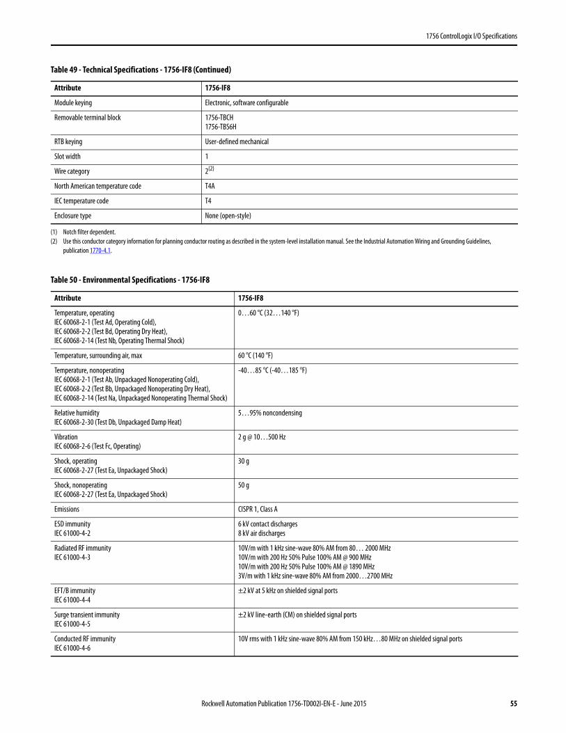
1756 ControlLogix I/O Specifications
Module keying Electronic, software configurable
Removable terminal block 1756-TBCH1756-TBS6H
RTB keying User-defined mechanical
Slot width 1
Wire category 2(2)
North American temperature code T4A
IEC temperature code T4
Enclosure type None (open-style)
(1) Notch filter dependent.(2) Use this conductor category information for planning conductor routing as described in the system-level installation manual. See the Industrial Automation Wiring and Grounding Guidelines,
publication 1770-4.1.
Table 50 - Environmental Specifications - 1756-IF8
Attribute 1756-IF8
Temperature, operatingIEC 60068-2-1 (Test Ad, Operating Cold),IEC 60068-2-2 (Test Bd, Operating Dry Heat),IEC 60068-2-14 (Test Nb, Operating Thermal Shock)
0…60 °C (32…140 °F)
Temperature, surrounding air, max 60 °C (140 °F)
Temperature, nonoperatingIEC 60068-2-1 (Test Ab, Unpackaged Nonoperating Cold),IEC 60068-2-2 (Test Bb, Unpackaged Nonoperating Dry Heat),IEC 60068-2-14 (Test Na, Unpackaged Nonoperating Thermal Shock)
-40…85 °C (-40…185 °F)
Relative humidityIEC 60068-2-30 (Test Db, Unpackaged Damp Heat)
5…95% noncondensing
VibrationIEC 60068-2-6 (Test Fc, Operating)
2 g @ 10…500 Hz
Shock, operatingIEC 60068-2-27 (Test Ea, Unpackaged Shock)
30 g
Shock, nonoperatingIEC 60068-2-27 (Test Ea, Unpackaged Shock)
50 g
Emissions CISPR 1, Class A
ESD immunityIEC 61000-4-2
6 kV contact discharges8 kV air discharges
Radiated RF immunityIEC 61000-4-3
10V/m with 1 kHz sine-wave 80% AM from 80… 2000 MHz10V/m with 200 Hz 50% Pulse 100% AM @ 900 MHz10V/m with 200 Hz 50% Pulse 100% AM @ 1890 MHz3V/m with 1 kHz sine-wave 80% AM from 2000…2700 MHz
EFT/B immunityIEC 61000-4-4
±2 kV at 5 kHz on shielded signal ports
Surge transient immunityIEC 61000-4-5
±2 kV line-earth (CM) on shielded signal ports
Conducted RF immunityIEC 61000-4-6
10V rms with 1 kHz sine-wave 80% AM from 150 kHz…80 MHz on shielded signal ports
Table 49 - Technical Specifications - 1756-IF8 (Continued)
Attribute 1756-IF8
Rockwell Automation Publication 1756-TD002I-EN-E - June 2015 55

1756 ControlLogix I/O Specifications
Table 51 - Certifications - 1756-IF8
Certification(1)
(1) When marked. See the Product Certification link at http://www.ab.com for Declarations of Conformity, Certificates, and other certification details.
1756-IF8
UL UL Listed Industrial Control Equipment. See UL File E65584.
CSA CSA Certified Process Control Equipment. See CSA File LR54689C.CSA Certified Process Control Equipment for Class I, Division 2 Group A,B,C,D Hazardous Locations. See CSA File LR69960C.
CE European Union 2004/108/IEC EMC Directive, compliant with:• EN 61326-1; Meas./Control/Lab., Industrial Requirements• EN 61000-6-2; Industrial Immunity• EN 61000-6-4; Industrial Emissions• EN 61131-2; Programmable Controllers (Clause 8, Zone A & B)European Union 2006/95/EC LVD, compliant with:EN 61131-2; Programmable Controllers (Clause 11)
C-Tick Australian Radiocommunications Act, compliant with:AS/NZS CISPR 11; Industrial Emissions
Ex European Union 94/9/EC ATEX Directive, compliant with:• EN 60079-15; Potentially Explosive Atmospheres, Protection "n"• EN 60079-0; General Requirements II 3 G Ex nA IIC T4 X Gc
FM FM Approved Equipment for use in Class I Division 2 Group A,B,C,D Hazardous Locations
KC Korean Registration of Broadcasting and Communications Equipment, compliant with:Article 58-2 of Radio Waves Act, Clause 3
56 Rockwell Automation Publication 1756-TD002I-EN-E - June 2015
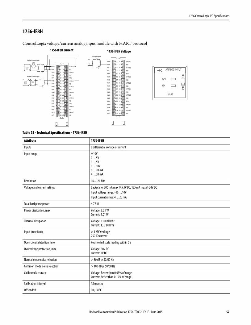
1756 ControlLogix I/O Specifications
1756-IF8H
ControlLogix voltage/current analog input module with HART protocol
Table 52 - Technical Specifications - 1756-IF8H
Attribute 1756-IF8H
Inputs 8 differential voltage or current
Input range ±10V0…5V1…5V0…10V0…20 mA4…20 mA
Resolution 16…21 bits
Voltage and current ratings Backplane: 300 mA max @ 5.1V DC, 135 mA max @ 24V DCInput voltage range: -10…10VInput current range: 4…20 mA
Total backplane power 4.77 W
Power dissipation, max Voltage: 3.21 WCurrent: 4.01 W
Thermal dissipation Voltage: 11.0 BTU/hrCurrent: 13.7 BTU/hr
Input impedance > 1 MΩ voltage250 Ω current
Open circuit detection time Positive full scale reading within 5 s
Overvoltage protection, max Voltage: 30V DCCurrent: 8V DC
Normal mode noise rejection > 80 dB @ 50/60 Hz
Common mode noise rejection > 100 dB @ 50/60 Hz
Calibrated accuracy Voltage: Better than 0.05% of rangeCurrent: Better than 0.15% of range
Calibration interval 12 months
Offset drift 90 μV/°C
RTN
IN4+
IN4-
IN5+
IN5-
RTN
IN6+
IN6-
IN7+
IN7-
IN0+
IN0-
IN1+
IN1-
IN2+
IN2-
IN3+
IN3-
I RTN-0
NC
I RTN-1
NC
I RTN-2
NC
I RTN-3
NC
RTN
I RTN-4
NC
I RTN-5
NC
RTN
I RTN-6
NC
I RTN-7
NC
2
4
6
8
10
12
14
16
18
20
22
24
26
28
30
32
34
36
1
3
5
7
9
11
13
15
17
19
21
23
25
27
29
31
33
35
2 Wire Current Input2 WireXMTR
+-
24V DCPowerSupply
+-
24V DCPowerSupply
4 Wire Current Input
4 WireXMTR
+ +
- -
+ -
RTN
IN4+
IN4-
IN5+
IN5-
RTN
IN6+
IN6-
IN7+
IN7-
IN0+
IN0-
IN1+
IN1-
IN2+
IN2-
IN3+
IN3-
I RTN-0
NC
I RTN-1
NC
I RTN-2
NC
I RTN-3
NC
RTN
I RTN-4
NC
I RTN-5
NC
RTN
I RTN-6
NC
I RTN-7
NC
2
4
6
8
10
12
14
16
18
20
22
24
26
28
30
32
34
36
1
3
5
7
9
11
13
15
17
19
21
23
25
27
29
31
33
35
+V
- V
Voltage Input
ANALOG INPUT
CAL
OK
HART
1756-IF8H Current1756-IF8H Current 1756-IF8H Voltage
Rockwell Automation Publication 1756-TD002I-EN-E - June 2015 57
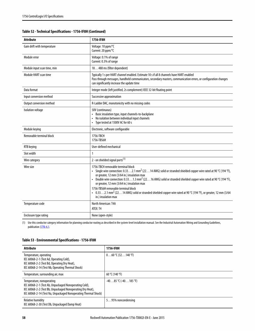
1756 ControlLogix I/O Specifications
Gain drift with temperature Voltage: 10 ppm/°CCurrent: 20 ppm/°C
Module error Voltage: 0.1% of rangeCurrent: 0.3% of range
Module input scan time, min 18…488 ms (filter dependent)
Module HART scan time Typically 1 s per HART channel enabled. Estimate 10 s if all 8 channels have HART enabledPass through messages, handheld communicators, secondary masters, communication errors, or configuration changes can significantly increase the update time
Data format Integer mode (left justified, 2s complement) IEEE 32-bit floating point
Input conversion method Successive approximation
Output conversion method R-Ladder DAC, monotonicity with no missing codes
Isolation voltage 50V (continuous)• Basic insulation type, input channels-to-backplane• No isolation between individual input channels• Type tested at 1500V AC for 60 s
Module keying Electronic, software configurable
Removable terminal block 1756-TBCH1756-TBS6H
RTB keying User-defined mechanical
Slot width 1
Wire category 2 - on shielded signal ports(1)
Wire size 1756-TBCH removable terminal block• Single wire connection: 0.33…2.1 mm2 (22…14 AWG) solid or stranded shielded copper wire rated at 90 °C (194 °F),
or greater, 12 mm (3/64 in.) insulation max• Double wire connection: 0.33…1.3 mm2 (22…16 AWG) solid or stranded shielded copper wire rated at 90 °C (194 °F),
or greater, 12 mm (3/64 in.) insulation max1756-TBS6H removable terminal block• 0.33…2.1 mm2 (22…14 AWG) solid or stranded shielded copper wire rated at 90 °C (194 °F), or greater, 12 mm (3/64
in.) insulation max
Temperature code North American: T4AATEX: T4
Enclosure type rating None (open-style)
(1) Use this conductor category information for planning conductor routing as described in the system-level installation manual. See the Industrial Automation Wiring and Grounding Guidelines, publication 1770-4.1.
Table 53 - Environmental Specifications - 1756-IF8H
Attribute 1756-IF8H
Temperature, operatingIEC 60068-2-1 (Test Ad, Operating Cold),IEC 60068-2-2 (Test Bd, Operating Dry Heat),IEC 60068-2-14 (Test Nb, Operating Thermal Shock)
0…60 °C (32…140 °F)
Temperature, surrounding air, max 60 °C (140 °F)
Temperature, nonoperatingIEC 60068-2-1 (Test Ab, Unpackaged Nonoperating Cold),IEC 60068-2-2 (Test Bb, Unpackaged Nonoperating Dry Heat),IEC 60068-2-14 (Test Na, Unpackaged Nonoperating Thermal Shock)
-40…85 °C (-40…185 °F)
Relative humidityIEC 60068-2-30 (Test Db, Unpackaged Damp Heat)
5…95% noncondensing
Table 52 - Technical Specifications - 1756-IF8H (Continued)
Attribute 1756-IF8H
58 Rockwell Automation Publication 1756-TD002I-EN-E - June 2015

1756 ControlLogix I/O Specifications
VibrationIEC 60068-2-6 (Test Fc, Operating)
2 g @ 10…500 Hz
ShockIEC 60068-2-27 (Test Ea, Unpackaged Shock)
Operating: 30 g Nonoperating: 50 g
Emissions IEC 61000-6-4
ESD immunityIEC 61000-4-2
6 kV contact discharges8 kV air discharges
Radiated RF immunityIEC 61000-4-3
10V/m with 1 kHz sine-wave 80% AM from 80… 2000 MHz10V/m with 200 Hz 50% Pulse 100% AM @ 900 MHz10V/m with 200 Hz 50% Pulse 100% AM @ 1890 MHz1V/m with 1 kHz sine-wave 80% AM from 2000…2700 MHz
EFT/B immunityIEC 61000-4-4
±2 kV at 5 kHz on shielded signal ports
Surge transient immunityIEC 61000-4-5
±2 kV line-earth (CM) on shielded signal ports
Conducted RF immunityIEC 61000-4-6
10V rms with 1 kHz sine-wave 80% AM from 150 kHz…80 MHz on shielded signal ports
Table 54 - Certifications - 1756-IF8H
Certification(1)
(1) When marked. See the Product Certification link at http://www.ab.com for Declarations of Conformity, Certificates, and other certification details.
1756-IF8H
c-UL-us UL Listed Industrial Control Equipment, certified for US and Canada. See UL File E65584.UL Listed for Class I, Division 2 Group A,B,C,D Hazardous Locations, certified for U.S. and Canada. See UL File E194810.
CE European Union 2004/108/IEC EMC Directive, compliant with:• EN 61326-1; Meas./Control/Lab., Industrial Requirements• EN 61000-6-2; Industrial Immunity• EN 61000-6-4; Industrial Emissions• EN 61131-2; Programmable Controllers (Clause 8, Zone A & B)
RCM Australian Radiocommunications Act, compliant with:EN 61000-6-4: Industrial Emissions
Ex European Union 94/9/EC ATEX Directive, compliant with:• EN 60079-15; Potentially Explosive Atmospheres, Protection "n"• EN 60079-0; General Requirements II 3 G Ex nA IIC T4 Gc DEMKO12ATEX1219040
KC Korean Registration of Broadcasting and Communications Equipment, compliant with:Article 58-2 of Radio Waves Act, Clause 3
EAC Russian Customs Union TR CU 020/2011 EMC Technical RegulationRussian Customs Union TR CU 004/2011 LV Technical Regulation
Table 53 - Environmental Specifications - 1756-IF8H (Continued)
Attribute 1756-IF8H
Rockwell Automation Publication 1756-TD002I-EN-E - June 2015 59
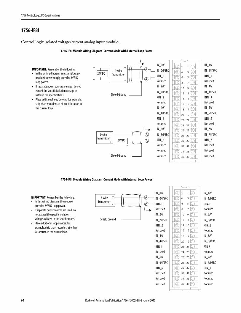
1756 ControlLogix I/O Specifications
1756-IF8I
ControlLogix isolated voltage/current analog input module.
i
+
-
A
A
1
3
5
7
01 9
1112
41 31
61 51
81 71
02 91
22 12
42 32
62 52
82 72
03 92
23 13
33
63 53
2
34
8
6
4
+
–
A
A
iA
A
i1
3
5
7
01 9
1112
41 31
61 51
81 71
02 91
22 12
42 32
62 52
82 72
03 92
23 13
33
63 53
2
34
8
6
4
+
–
IN_0/V
IN_0/I/SRC
RTN_0Not used
IN_2/V
IN_2/I/SRC
RTN_2Not used
4-wire Transmitter
Shield Ground
IN_4/V
IN_4/I/SRC
RTN_4Not used
IN_6/V
IN_6/I/SRC
RTN_6Not used
Not used
Not used
IN_1/V
IN_1/I/SRC
RTN_1Not used
IN_3/V
IN_3/I/SRC
RTN_3Not used
IN_5/V
IN_5/I/SRC
RTN_5Not used
IN_7/V
IN_7/I/SRC
RTN_7Not used
Not used
Not used
24V DC
IMPORTANT: Remember the following:• In this wiring diagram, an external, user-
provided power supply provides 24V DC loop power.
• If separate power sources are used, do not exceed the specific isolation voltage as listed in the specifications.
• Place additional loop devices, for example, strip chart recorders, at either ‘A’ location in the current loop.
24V DC
2-wire Transmitter
Shield Ground
1756-IF8I Module Wiring Diagram -Current Mode with External Loop Power
IN_0/V
IN_0/I/SRC
RTN-0Not used
IN_2/V
IN_2/I/SRC
RTN_2Not used
Shield Ground
IN_4/V
IN_4/I/SRC
RTN-4Not used
IN_6/V
IN_6/I/SRC
RTN_6Not used
Not used
Not used
IN_1/V
IN_1/I/SRC
RTN-1Not used
IN_3/V
IN_3/I/SRC
RTN_3Not used
IN_5/V
IN_5/I/SRC
RTN-5Not used
IN_7/V
IN_7/I/SRC
RTN_7Not used
Not used
Not used
IMPORTANT: Remember the following:• In this wiring diagram, the module
provides 24V DC loop power.• If separate power sources are used, do
not exceed the specific isolation voltage as listed in the specifications.
• Place additional loop devices, for example, strip chart recorders, at either ‘A’ location in the current loop.
2-wire Transmitter
1756-IF8I Module Wiring Diagram -Current Mode with Internal Loop Power
+
–
+ –
60 Rockwell Automation Publication 1756-TD002I-EN-E - June 2015
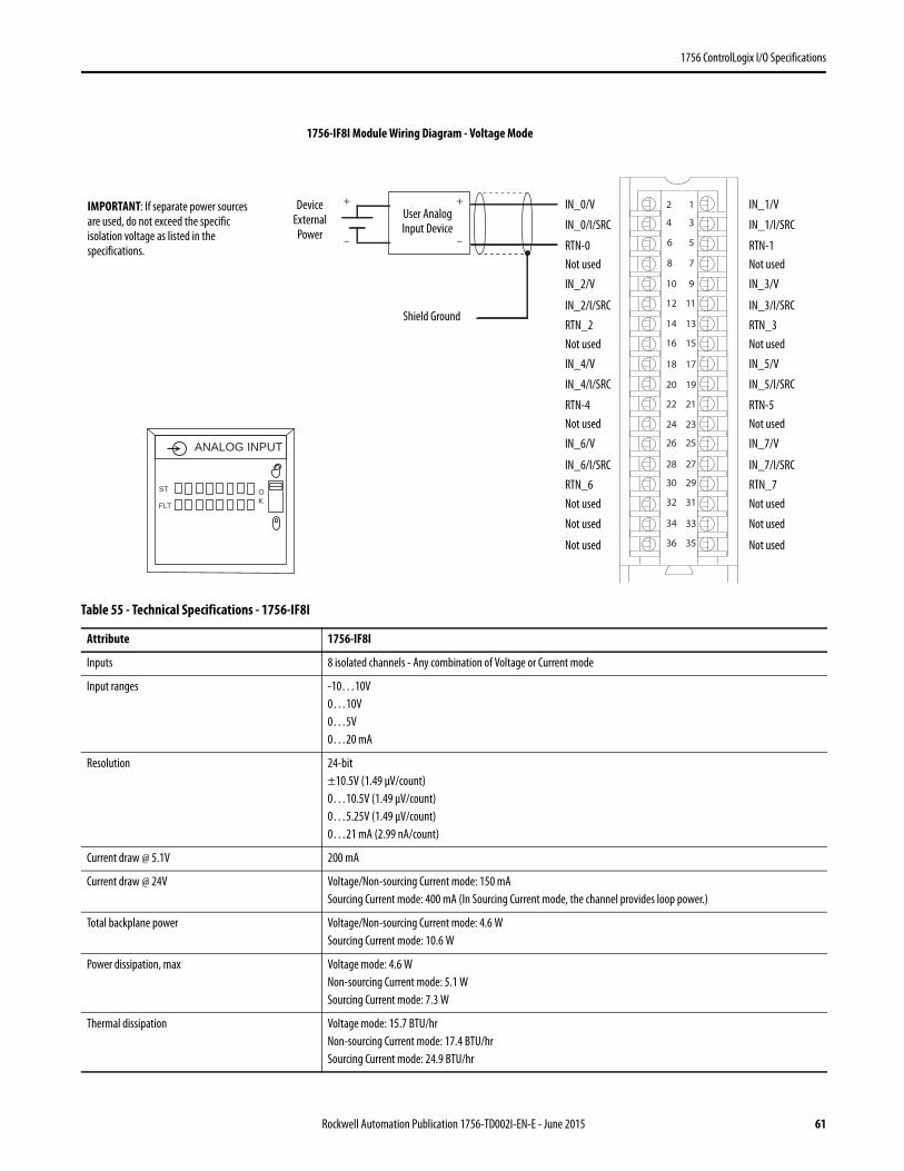
1756 ControlLogix I/O Specifications
Table 55 - Technical Specifications - 1756-IF8I
Attribute 1756-IF8I
Inputs 8 isolated channels - Any combination of Voltage or Current mode
Input ranges -10…10V0…10V0…5V0…20 mA
Resolution 24-bit±10.5V (1.49 μV/count)0…10.5V (1.49 μV/count)0…5.25V (1.49 μV/count)0…21 mA (2.99 nA/count)
Current draw @ 5.1V 200 mA
Current draw @ 24V Voltage/Non-sourcing Current mode: 150 mASourcing Current mode: 400 mA (In Sourcing Current mode, the channel provides loop power.)
Total backplane power Voltage/Non-sourcing Current mode: 4.6 WSourcing Current mode: 10.6 W
Power dissipation, max Voltage mode: 4.6 WNon-sourcing Current mode: 5.1 WSourcing Current mode: 7.3 W
Thermal dissipation Voltage mode: 15.7 BTU/hrNon-sourcing Current mode: 17.4 BTU/hrSourcing Current mode: 24.9 BTU/hr
+
–
1
3
5
7
01 9
1112
41 31
61 51
81 71
02 91
22 12
42 32
62 52
82 72
03 92
23 13
33
63 53
2
34
8
6
4
+
–
ST
FLT
ANALOG INPUT
OK
IN_0/V
IN_0/I/SRC
RTN-0Not used
IN_2/V
IN_2/I/SRC
RTN_2Not used
User Analog Input Device
Shield Ground
IMPORTANT: If separate power sources are used, do not exceed the specific isolation voltage as listed in the specifications.
IN_4/V
IN_4/I/SRC
RTN-4Not used
IN_6/V
IN_6/I/SRC
RTN_6Not used
Not used
Not used
IN_1/V
IN_1/I/SRC
RTN-1Not used
IN_3/V
IN_3/I/SRC
RTN_3Not used
IN_5/V
IN_5/I/SRC
RTN-5Not used
IN_7/V
IN_7/I/SRC
RTN_7Not used
Not used
Not used
Device External Power
1756-IF8I Module Wiring Diagram - Voltage Mode
Rockwell Automation Publication 1756-TD002I-EN-E - June 2015 61
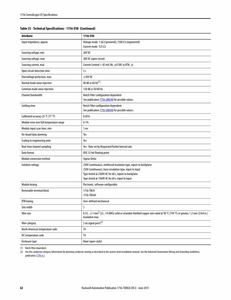
1756 ControlLogix I/O Specifications
Input impedance, approx Voltage mode: 1 GΩ (powered); 7500 Ω (unpowered)Current mode: 125 Ω
Sourcing voltage, min 20V DC
Sourcing voltage, max 38V DC (open circuit)
Sourcing current, max Current Limited < 45 mA (IN_x/I/SRC to RTN_x)
Open circuit detection time 5 s
Overvoltage protection, max ±30V DC
Normal mode noise rejection 80 dB @ 60 Hz(1)
Common mode noise rejection 120 dB @ 50/60 Hz
Channel bandwidth Notch Filter configuration dependentSee publication 1756-UM540 for possible values.
Settling time Notch Filter configuration dependentSee publication 1756-UM540 for possible values.
Calibrated accuracy 25 °C (77 °F) 0.05%
Module error over full temperature range 0.1%
Module input scan time, min 1 ms
On-board data alarming Yes
Scaling to engineering units Yes
Real-time channel sampling Yes - Rate set by Requested Packet Interval rate
Data format IEEE 32-bit floating point
Module conversion method Sigma-Delta
Isolation voltage 250V (continuous), reinforced insulation type, inputs to backplane250V (continuous), basic insulation type, input to inputType tested at 2300V AC for 60 s, inputs to backplaneType tested at 1500V AC for 60 s, input to input
Module keying Electronic, software configurable
Removable terminal block 1756-TBCH1756-TBS6H
RTB keying User-defined mechanical
Slot width 1
Wire size 0.33... 2.1 mm2 (22...14 AWG) solid or stranded shielded copper wire rated at 90 °C (194 °F) or greater, 1.2 mm (3/64 in.) insulation max
Wire category 2 on signal ports(2)
North American temperature code T4
IEC temperature code T4
Enclosure type None (open-style)
(1) Notch filter dependent.(2) Use this conductor category information for planning conductor routing as described in the system-level installation manual. See the Industrial Automation Wiring and Grounding Guidelines,
publication 1770-4.1.
Table 55 - Technical Specifications - 1756-IF8I (Continued)
Attribute 1756-IF8I
62 Rockwell Automation Publication 1756-TD002I-EN-E - June 2015

1756 ControlLogix I/O Specifications
Table 56 - Environmental Specifications - 1756-IF8I
Attribute 1756-IF8I
Temperature, operatingIEC 60068-2-1 (Test Ad, Operating Cold),IEC 60068-2-2 (Test Bd, Operating Dry Heat),IEC 60068-2-14 (Test Nb, Operating Thermal Shock)
0…60 °C (32…140 °F)
Temperature, surrounding air, max 60 °C (140 °F)
Temperature, nonoperatingIEC 60068-2-1 (Test Ab, Unpackaged Nonoperating Cold),IEC 60068-2-2 (Test Bb, Unpackaged Nonoperating Dry Heat),IEC 60068-2-14 (Test Na, Unpackaged Nonoperating Thermal Shock)
-40…85 °C (-40…185 °F)
Relative humidityIEC 60068-2-30 (Test Db, Unpackaged Damp Heat)
5…95% noncondensing
VibrationIEC 60068-2-6 (Test Fc, Operating)
2 g @ 10…500 Hz
Shock, operatingIEC 60068-2-27 (Test Ea, Unpackaged Shock)
30 g
Shock, nonoperatingIEC 60068-2-27 (Test Ea, Unpackaged Shock)
50 g
Emissions CISPR 11, Class A
ESD immunityIEC 61000-4-2
6 kV contact discharges8 kV air discharges
Radiated RF immunityIEC 61000-4-3
10V/m with 1 kHz sine-wave 80% AM from 80… 2000 MHz10V/m with 200 Hz 50% Pulse 100% AM @ 900 MHz10V/m with 200 Hz 50% Pulse 100% AM @ 1890 MHz3V/m with 1 kHz sine-wave 80% AM from 2000…2700 MHz
EFT/B immunityIEC 61000-4-4
±4 kV at 5 kHz on shielded signal ports
Surge transient immunityIEC 61000-4-5
±2 kV line-earth (CM) on shielded signal ports
Conducted RF immunityIEC 61000-4-6
10V rms with 1 kHz sine-wave 80% AM from 150 kHz…80 MHz
Table 57 - Certifications - 1756-IF8I
Certification(1)
(1) When marked. See the Product Certification link at http://www.ab.com for Declarations of Conformity, Certificates, and other certification details.
1756-IF8I
c-UL-us UL Listed Industrial Control Equipment, certified for US and Canada. See UL File E65584.UL Listed for Class I, Division 2 Group A,B,C,D Hazardous Locations, certified for U.S. and Canada. See UL File E194810.
CE European Union 2004/108/IEC EMC Directive, compliant with:• EN 61326-1; Meas./Control/Lab., Industrial Requirements• EN 61000-6-2; Industrial Immunity• EN 61000-6-4; Industrial Emissions• EN 61131-2; Programmable Controllers (Clause 8, Zone A & B)European Union 2006/95/EC LVD, compliant with:• EN 61131-2; Programmable Controllers (Clause 11)
C-Tick Australian Radiocommunications Act, compliant with:• EN 61000-6-4; Industrial Emissions
Ex European Union 94/9/EC ATEX Directive, compliant with:• EN 60079-15; Potentially Explosive Atmospheres, Protection "n"• EN 60079-0; General Requirements II 3 G Ex nA IIC T4 Gc X
KC Korean Registration of Broadcasting and Communications Equipment, compliant with:• Article 58-2 of Radio Waves Act, Clause 3
Rockwell Automation Publication 1756-TD002I-EN-E - June 2015 63
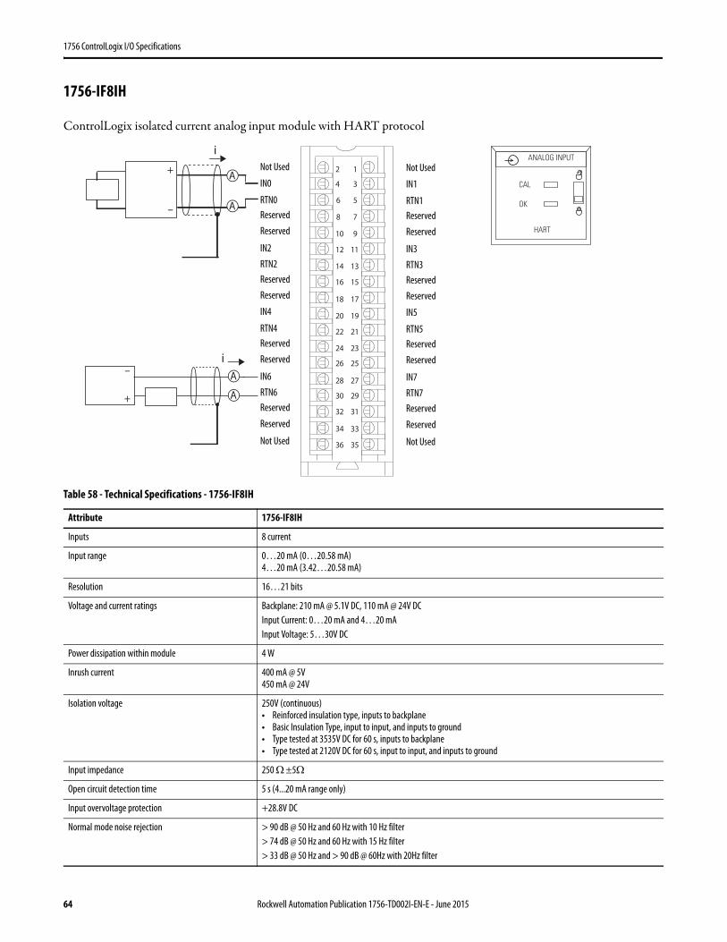
1756 ControlLogix I/O Specifications
1756-IF8IH
ControlLogix isolated current analog input module with HART protocol
Table 58 - Technical Specifications - 1756-IF8IH
Attribute 1756-IF8IH
Inputs 8 current
Input range 0…20 mA (0…20.58 mA)4…20 mA (3.42…20.58 mA)
Resolution 16…21 bits
Voltage and current ratings Backplane: 210 mA @ 5.1V DC, 110 mA @ 24V DCInput Current: 0…20 mA and 4…20 mAInput Voltage: 5…30V DC
Power dissipation within module 4 W
Inrush current 400 mA @ 5V450 mA @ 24V
Isolation voltage 250V (continuous)• Reinforced insulation type, inputs to backplane• Basic Insulation Type, input to input, and inputs to ground• Type tested at 3535V DC for 60 s, inputs to backplane• Type tested at 2120V DC for 60 s, input to input, and inputs to ground
Input impedance 250 Ω ±5Ω
Open circuit detection time 5 s (4...20 mA range only)
Input overvoltage protection +28.8V DC
Normal mode noise rejection > 90 dB @ 50 Hz and 60 Hz with 10 Hz filter> 74 dB @ 50 Hz and 60 Hz with 15 Hz filter> 33 dB @ 50 Hz and > 90 dB @ 60Hz with 20Hz filter
+
–
A
A
iA
A
i1
3
5
7
01 9
1112
41 31
61 51
81 71
02 91
22 12
42 32
62 52
82 72
03 92
23 13
33
63 53
2
34
8
6
4
+
–
ANALOG INPUT
CAL
OK
HART
Not Used
IN1
RTN1Reserved
Reserved
IN3
RTN3Reserved
Reserved
IN5
RTN5Reserved
Reserved
IN7
RTN7Reserved
Reserved
Not Used
Not Used
IN0
RTN0Reserved
Reserved
IN2
RTN2Reserved
Reserved
IN4
RTN4Reserved
Reserved
IN6
RTN6Reserved
Reserved
Not Used
64 Rockwell Automation Publication 1756-TD002I-EN-E - June 2015
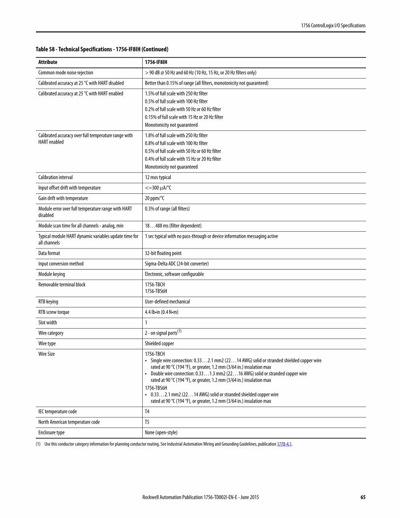
1756 ControlLogix I/O Specifications
Common mode noise rejection > 90 dB @ 50 Hz and 60 Hz (10 Hz, 15 Hz, or 20 Hz filters only)
Calibrated accuracy at 25 °C with HART disabled Better than 0.15% of range (all filters, monotonicity not guaranteed)
Calibrated accuracy at 25 °C with HART enabled 1.5% of full scale with 250 Hz filter0.5% of full scale with 100 Hz filter0.2% of full scale with 50 Hz or 60 Hz filter0.15% of full scale with 15 Hz or 20 Hz filterMonotonicity not guaranteed
Calibrated accuracy over full temperature range with HART enabled
1.8% of full scale with 250 Hz filter0.8% of full scale with 100 Hz filter0.5% of full scale with 50 Hz or 60 Hz filter0.4% of full scale with 15 Hz or 20 Hz filterMonotonicity not guaranteed
Calibration interval 12 mos typical
Input offset drift with temperature <=300 μA/°C
Gain drift with temperature 20 ppm/°C
Module error over full temperature range with HART disabled
0.3% of range (all filters)
Module scan time for all channels - analog, min 18…488 ms (filter dependent)
Typical module HART dynamic variables update time for all channels
1 sec typical with no pass-through or device information messaging active
Data format 32-bit floating point
Input conversion method Sigma-Delta ADC (24-bit converter)
Module keying Electronic, software configurable
Removable terminal block 1756-TBCH1756-TBS6H
RTB keying User-defined mechanical
RTB screw torque 4.4 lb•in (0.4 N•m)
Slot width 1
Wire category 2 - on signal ports(1)
Wire type Shielded copper
Wire Size 1756-TBCH• Single wire connection: 0.33…2.1 mm2 (22…14 AWG) solid or stranded shielded copper wire
rated at 90 °C (194 °F), or greater, 1.2 mm (3/64 in.) insulation max• Double wire connection: 0.33…1.3 mm2 (22…16 AWG) solid or stranded copper wire
rated at 90 °C (194 °F), or greater, 1.2 mm (3/64 in.) insulation max1756-TBS6H• 0.33…2.1 mm2 (22…14 AWG) solid or stranded shielded copper wire
rated at 90 °C (194 °F), or greater, 1.2 mm (3/64 in.) insulation max
IEC temperature code T4
North American temperature code T5
Enclosure type None (open-style)
(1) Use this conductor category information for planning conductor routing. See Industrial Automation Wiring and Grounding Guidelines, publication 1770-4.1.
Table 58 - Technical Specifications - 1756-IF8IH (Continued)
Attribute 1756-IF8IH
Rockwell Automation Publication 1756-TD002I-EN-E - June 2015 65
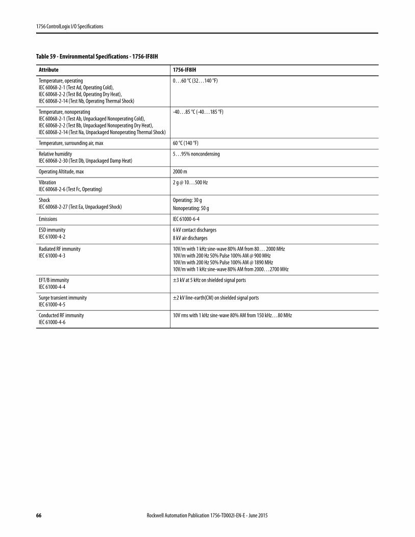
1756 ControlLogix I/O Specifications
Table 59 - Environmental Specifications - 1756-IF8IH
Attribute 1756-IF8IH
Temperature, operatingIEC 60068-2-1 (Test Ad, Operating Cold),IEC 60068-2-2 (Test Bd, Operating Dry Heat),IEC 60068-2-14 (Test Nb, Operating Thermal Shock)
0…60 °C (32…140 °F)
Temperature, nonoperatingIEC 60068-2-1 (Test Ab, Unpackaged Nonoperating Cold),IEC 60068-2-2 (Test Bb, Unpackaged Nonoperating Dry Heat),IEC 60068-2-14 (Test Na, Unpackaged Nonoperating Thermal Shock)
-40…85 °C (-40…185 °F)
Temperature, surrounding air, max 60 °C (140 °F)
Relative humidityIEC 60068-2-30 (Test Db, Unpackaged Damp Heat)
5…95% noncondensing
Operating Altitude, max 2000 m
VibrationIEC 60068-2-6 (Test Fc, Operating)
2 g @ 10…500 Hz
ShockIEC 60068-2-27 (Test Ea, Unpackaged Shock)
Operating: 30 g Nonoperating: 50 g
Emissions IEC 61000-6-4
ESD immunityIEC 61000-4-2
6 kV contact discharges8 kV air discharges
Radiated RF immunityIEC 61000-4-3
10V/m with 1 kHz sine-wave 80% AM from 80… 2000 MHz10V/m with 200 Hz 50% Pulse 100% AM @ 900 MHz10V/m with 200 Hz 50% Pulse 100% AM @ 1890 MHz10V/m with 1 kHz sine-wave 80% AM from 2000…2700 MHz
EFT/B immunityIEC 61000-4-4
±3 kV at 5 kHz on shielded signal ports
Surge transient immunityIEC 61000-4-5
±2 kV line-earth(CM) on shielded signal ports
Conducted RF immunityIEC 61000-4-6
10V rms with 1 kHz sine-wave 80% AM from 150 kHz…80 MHz
66 Rockwell Automation Publication 1756-TD002I-EN-E - June 2015
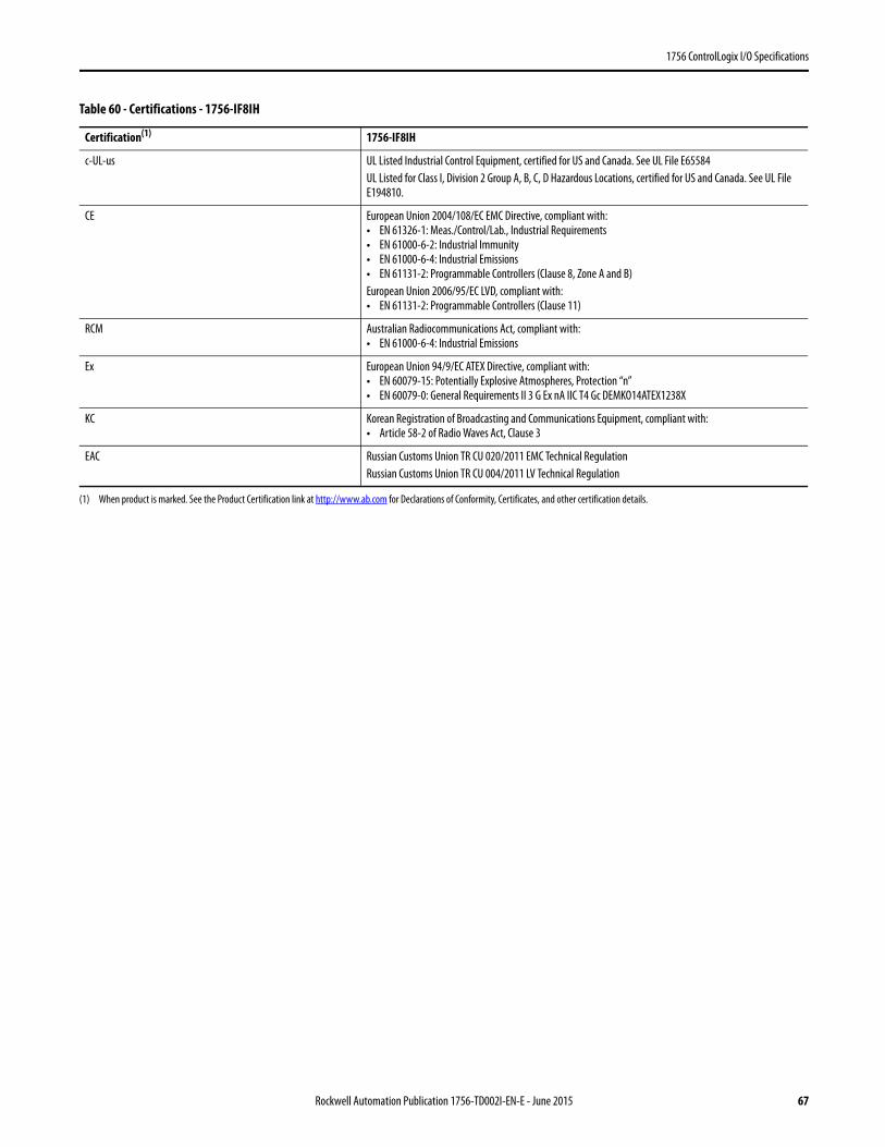
1756 ControlLogix I/O Specifications
Table 60 - Certifications - 1756-IF8IH
Certification(1) 1756-IF8IH
c-UL-us UL Listed Industrial Control Equipment, certified for US and Canada. See UL File E65584UL Listed for Class I, Division 2 Group A, B, C, D Hazardous Locations, certified for US and Canada. See UL File E194810.
CE European Union 2004/108/EC EMC Directive, compliant with:• EN 61326-1: Meas./Control/Lab., Industrial Requirements• EN 61000-6-2: Industrial Immunity• EN 61000-6-4: Industrial Emissions• EN 61131-2: Programmable Controllers (Clause 8, Zone A and B)European Union 2006/95/EC LVD, compliant with:• EN 61131-2: Programmable Controllers (Clause 11)
RCM Australian Radiocommunications Act, compliant with:• EN 61000-6-4: Industrial Emissions
Ex European Union 94/9/EC ATEX Directive, compliant with:• EN 60079-15: Potentially Explosive Atmospheres, Protection “n”• EN 60079-0: General Requirements II 3 G Ex nA IIC T4 Gc DEMKO14ATEX1238X
KC Korean Registration of Broadcasting and Communications Equipment, compliant with:• Article 58-2 of Radio Waves Act, Clause 3
EAC Russian Customs Union TR CU 020/2011 EMC Technical RegulationRussian Customs Union TR CU 004/2011 LV Technical Regulation
(1) When product is marked. See the Product Certification link at http://www.ab.com for Declarations of Conformity, Certificates, and other certification details.
Rockwell Automation Publication 1756-TD002I-EN-E - June 2015 67
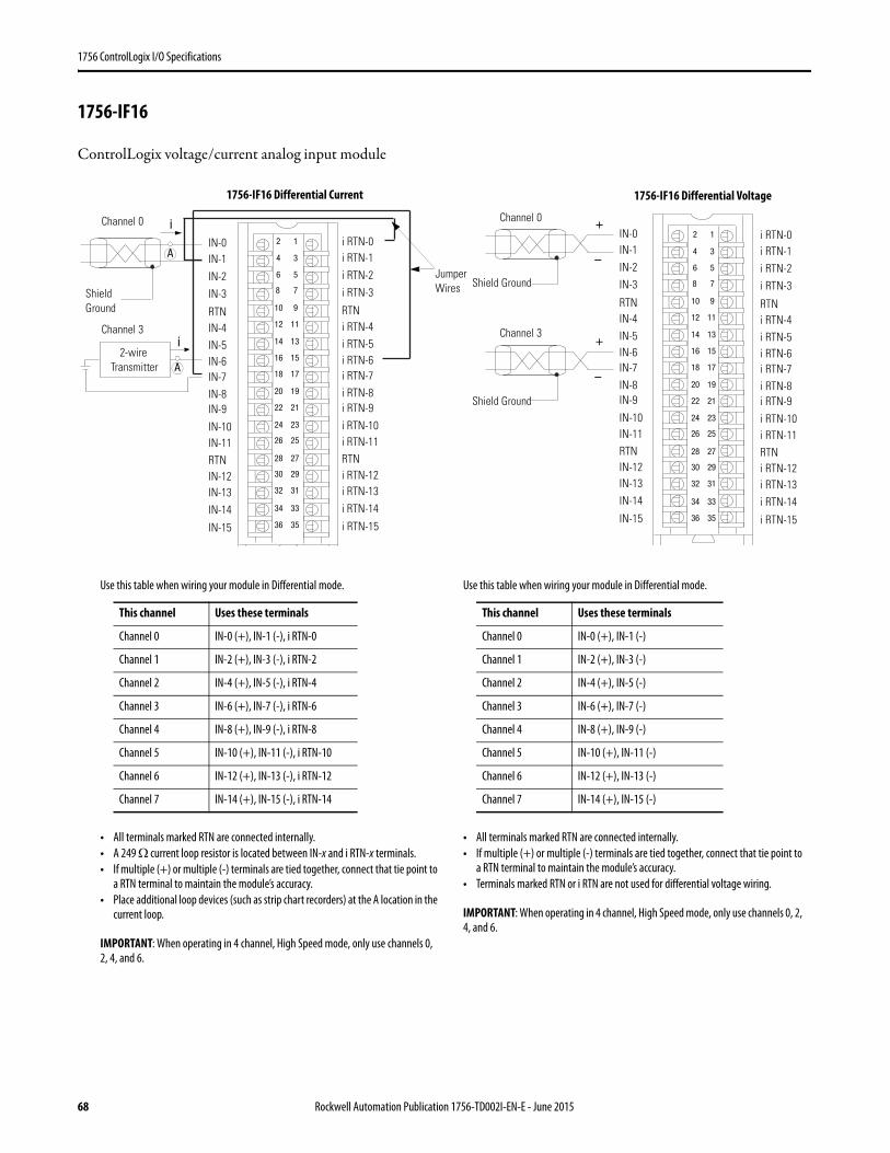
1756 ControlLogix I/O Specifications
1756-IF16
ControlLogix voltage/current analog input module
12
34
56
78
910
1112
1314
1516
1718
1920
2122
2324
2526
2728
2930
3132
3334
3536
Shield Ground
Channel 0
Channel 3
Jumper Wires
i
i
A
2-wire Transmitter A
IN-0IN-1
IN-2IN-3
IN-7
RTNIN-4IN-5IN-6
IN-15
IN-8IN-9
IN-10IN-11RTNIN-12IN-13IN-14
i RTN-0i RTN-1
i RTN-2i RTN-3
i RTN-7
RTNi RTN-4i RTN-5i RTN-6
i RTN-15
i RTN-8i RTN-9
i RTN-10i RTN-11RTNi RTN-12i RTN-13i RTN-14
12
34
56
78
910
1112
1314
1516
1718
1920
2122
2324
2526
2728
2930
3132
3334
3536
+
–
+
–
Shield Ground
Channel 0
Channel 3
IN-0IN-1IN-2IN-3
IN-7
RTNIN-4IN-5IN-6
IN-15
IN-8IN-9
IN-10IN-11RTNIN-12IN-13IN-14
i RTN-0i RTN-1i RTN-2i RTN-3
i RTN-7
RTNi RTN-4i RTN-5i RTN-6
i RTN-15
i RTN-8i RTN-9
i RTN-10i RTN-11RTNi RTN-12i RTN-13i RTN-14
Shield Ground
Use this table when wiring your module in Differential mode.
• All terminals marked RTN are connected internally.• A 249 Ω current loop resistor is located between IN-x and i RTN-x terminals.• If multiple (+) or multiple (-) terminals are tied together, connect that tie point to
a RTN terminal to maintain the module’s accuracy.• Place additional loop devices (such as strip chart recorders) at the A location in the
current loop.
IMPORTANT: When operating in 4 channel, High Speed mode, only use channels 0, 2, 4, and 6.
This channel Uses these terminals
Channel 0 IN-0 (+), IN-1 (-), i RTN-0
Channel 1 IN-2 (+), IN-3 (-), i RTN-2
Channel 2 IN-4 (+), IN-5 (-), i RTN-4
Channel 3 IN-6 (+), IN-7 (-), i RTN-6
Channel 4 IN-8 (+), IN-9 (-), i RTN-8
Channel 5 IN-10 (+), IN-11 (-), i RTN-10
Channel 6 IN-12 (+), IN-13 (-), i RTN-12
Channel 7 IN-14 (+), IN-15 (-), i RTN-14
Use this table when wiring your module in Differential mode.
• All terminals marked RTN are connected internally.• If multiple (+) or multiple (-) terminals are tied together, connect that tie point to
a RTN terminal to maintain the module’s accuracy.• Terminals marked RTN or i RTN are not used for differential voltage wiring.
IMPORTANT: When operating in 4 channel, High Speed mode, only use channels 0, 2, 4, and 6.
This channel Uses these terminals
Channel 0 IN-0 (+), IN-1 (-)
Channel 1 IN-2 (+), IN-3 (-)
Channel 2 IN-4 (+), IN-5 (-)
Channel 3 IN-6 (+), IN-7 (-)
Channel 4 IN-8 (+), IN-9 (-)
Channel 5 IN-10 (+), IN-11 (-)
Channel 6 IN-12 (+), IN-13 (-)
Channel 7 IN-14 (+), IN-15 (-)
1756-IF16 Differential Current 1756-IF16 Differential Voltage
68 Rockwell Automation Publication 1756-TD002I-EN-E - June 2015
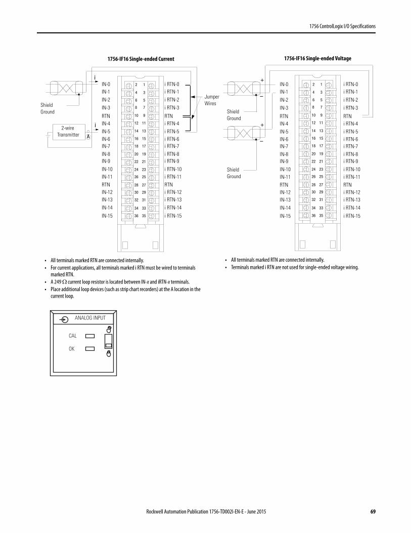
1756 ControlLogix I/O Specifications
12
34
56
78
910
1112
1314
1516
1718
1920
2122
2324
2526
2728
2930
3132
3334
3536
Shield Ground
Jumper Wires
i
i
A
2-wire Transmitter
IN-0IN-1IN-2IN-3
IN-7
RTNIN-4IN-5IN-6
IN-15
IN-8IN-9
IN-10IN-11RTNIN-12IN-13IN-14
i RTN-0i RTN-1i RTN-2i RTN-3
i RTN-7
RTNi RTN-4i RTN-5i RTN-6
i RTN-15
i RTN-8i RTN-9
i RTN-10i RTN-11RTNi RTN-12i RTN-13i RTN-14
12
34
56
78
910
1112
1314
1516
1718
1920
2122
2324
2526
2728
2930
3132
3334
3536
+
–
+
–
Shield Ground
IN-0IN-1
IN-2IN-3
IN-7
RTNIN-4IN-5IN-6
IN-15
IN-8IN-9
IN-10IN-11RTNIN-12IN-13
IN-14
i RTN-0i RTN-1
i RTN-2i RTN-3
i RTN-7
RTNi RTN-4i RTN-5i RTN-6
i RTN-15
i RTN-8i RTN-9
i RTN-10i RTN-11RTNi RTN-12i RTN-13
i RTN-14
Shield Ground
• All terminals marked RTN are connected internally.• For current applications, all terminals marked i RTN must be wired to terminals
marked RTN.• A 249 Ω current loop resistor is located between IN-x and iRTN-x terminals.• Place additional loop devices (such as strip chart recorders) at the A location in the
current loop.
• All terminals marked RTN are connected internally.• Terminals marked i RTN are not used for single-ended voltage wiring.
ANALOG INPUT
CAL
OK
1756-IF16 Single-ended Current 1756-IF16 Single-ended Voltage
Rockwell Automation Publication 1756-TD002I-EN-E - June 2015 69
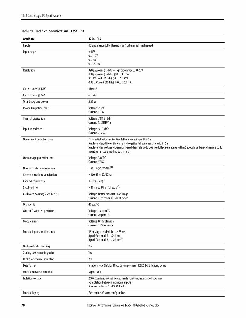
1756 ControlLogix I/O Specifications
Table 61 - Technical Specifications - 1756-IF16
Attribute 1756-IF16
Inputs 16 single ended, 8 differential or 4 differential (high speed)
Input range ±10V0…10V0…5V0…20 mA
Resolution 320 μV/count (15 bits + sign bipolar) @ ±10.25V160 μV/count (16 bits) @ 0…10.25V80 μV/count (16 bits) @ 0…5.125V0.32 μA/count (16 bits) @ 0…20.5 mA
Current draw @ 5.1V 150 mA
Current draw @ 24V 65 mA
Total backplane power 2.33 W
Power dissipation, max Voltage: 2.3 WCurrent: 3.9 W
Thermal dissipation Voltage: 7.84 BTU/hrCurrent: 13.3 BTU/hr
Input impedance Voltage: >10 MΩCurrent: 249 Ω
Open circuit detection time Differential voltage - Positive full scale reading within 5 sSingle-ended/differential current - Negative full scale reading within 5 sSingle-ended voltage - Even numbered channels go to positive full scale reading within 5 s, odd numbered channels go to negative full scale reading within 5 s
Overvoltage protection, max Voltage: 30V DCCurrent: 8V DC
Normal mode noise rejection >80 dB @ 50/60 Hz(1)
Common mode noise rejection >100 dB @ 50/60 Hz
Channel bandwidth 15 Hz (-3 dB)(1)
Settling time <80 ms to 5% of full scale(1)
Calibrated accuracy 25 °C (77 °F) Voltage: Better than 0.05% of rangeCurrent: Better than 0.15% of range
Offset drift 45 μV/°C
Gain drift with temperature Voltage: 15 ppm/°CCurrent: 20 ppm/°C
Module error Voltage: 0.1% of rangeCurrent: 0.3% of range
Module input scan time, min 16 pt single-ended: 16…488 ms8 pt differential: 8…244 ms4 pt differential: 5…122 ms(1)
On-board data alarming Yes
Scaling to engineering units Yes
Real-time channel sampling Yes
Data format Integer mode (left justified, 2s complement) IEEE 32-bit floating point
Module conversion method Sigma-Delta
Isolation voltage 250V (continuous), reinforced insulation type, inputs-to-backplaneNo isolation between individual inputsRoutine tested at 1350V AC for 2 s
Module keying Electronic, software configurable
70 Rockwell Automation Publication 1756-TD002I-EN-E - June 2015
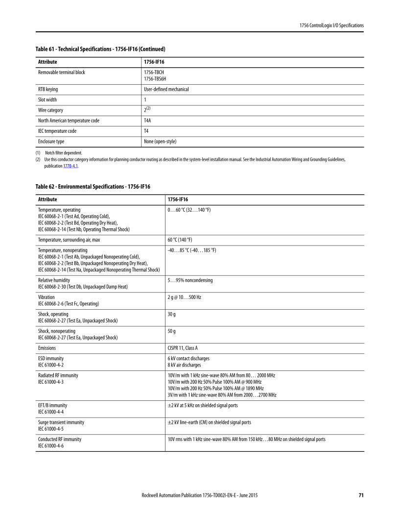
1756 ControlLogix I/O Specifications
Removable terminal block 1756-TBCH1756-TBS6H
RTB keying User-defined mechanical
Slot width 1
Wire category 2(2)
North American temperature code T4A
IEC temperature code T4
Enclosure type None (open-style)
(1) Notch filter dependent.(2) Use this conductor category information for planning conductor routing as described in the system-level installation manual. See the Industrial Automation Wiring and Grounding Guidelines,
publication 1770-4.1.
Table 62 - Environmental Specifications - 1756-IF16
Attribute 1756-IF16
Temperature, operatingIEC 60068-2-1 (Test Ad, Operating Cold),IEC 60068-2-2 (Test Bd, Operating Dry Heat),IEC 60068-2-14 (Test Nb, Operating Thermal Shock)
0…60 °C (32…140 °F)
Temperature, surrounding air, max 60 °C (140 °F)
Temperature, nonoperatingIEC 60068-2-1 (Test Ab, Unpackaged Nonoperating Cold),IEC 60068-2-2 (Test Bb, Unpackaged Nonoperating Dry Heat),IEC 60068-2-14 (Test Na, Unpackaged Nonoperating Thermal Shock)
-40…85 °C (-40…185 °F)
Relative humidityIEC 60068-2-30 (Test Db, Unpackaged Damp Heat)
5…95% noncondensing
VibrationIEC 60068-2-6 (Test Fc, Operating)
2 g @ 10…500 Hz
Shock, operatingIEC 60068-2-27 (Test Ea, Unpackaged Shock)
30 g
Shock, nonoperatingIEC 60068-2-27 (Test Ea, Unpackaged Shock)
50 g
Emissions CISPR 11, Class A
ESD immunityIEC 61000-4-2
6 kV contact discharges8 kV air discharges
Radiated RF immunityIEC 61000-4-3
10V/m with 1 kHz sine-wave 80% AM from 80… 2000 MHz10V/m with 200 Hz 50% Pulse 100% AM @ 900 MHz10V/m with 200 Hz 50% Pulse 100% AM @ 1890 MHz3V/m with 1 kHz sine-wave 80% AM from 2000…2700 MHz
EFT/B immunityIEC 61000-4-4
±2 kV at 5 kHz on shielded signal ports
Surge transient immunityIEC 61000-4-5
±2 kV line-earth (CM) on shielded signal ports
Conducted RF immunityIEC 61000-4-6
10V rms with 1 kHz sine-wave 80% AM from 150 kHz…80 MHz on shielded signal ports
Table 61 - Technical Specifications - 1756-IF16 (Continued)
Attribute 1756-IF16
Rockwell Automation Publication 1756-TD002I-EN-E - June 2015 71
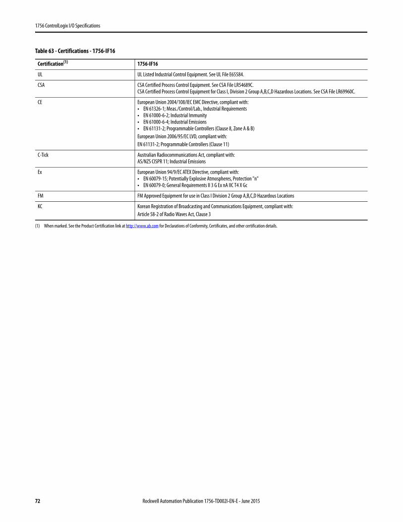
1756 ControlLogix I/O Specifications
Table 63 - Certifications - 1756-IF16
Certification(1)
(1) When marked. See the Product Certification link at http://www.ab.com for Declarations of Conformity, Certificates, and other certification details.
1756-IF16
UL UL Listed Industrial Control Equipment. See UL File E65584.
CSA CSA Certified Process Control Equipment. See CSA File LR54689C.CSA Certified Process Control Equipment for Class I, Division 2 Group A,B,C,D Hazardous Locations. See CSA File LR69960C.
CE European Union 2004/108/IEC EMC Directive, compliant with:• EN 61326-1; Meas./Control/Lab., Industrial Requirements• EN 61000-6-2; Industrial Immunity• EN 61000-6-4; Industrial Emissions• EN 61131-2; Programmable Controllers (Clause 8, Zone A & B)European Union 2006/95/EC LVD, compliant with:EN 61131-2; Programmable Controllers (Clause 11)
C-Tick Australian Radiocommunications Act, compliant with:AS/NZS CISPR 11; Industrial Emissions
Ex European Union 94/9/EC ATEX Directive, compliant with:• EN 60079-15; Potentially Explosive Atmospheres, Protection "n"• EN 60079-0; General Requirements II 3 G Ex nA IIC T4 X Gc
FM FM Approved Equipment for use in Class I Division 2 Group A,B,C,D Hazardous Locations
KC Korean Registration of Broadcasting and Communications Equipment, compliant with:Article 58-2 of Radio Waves Act, Clause 3
72 Rockwell Automation Publication 1756-TD002I-EN-E - June 2015
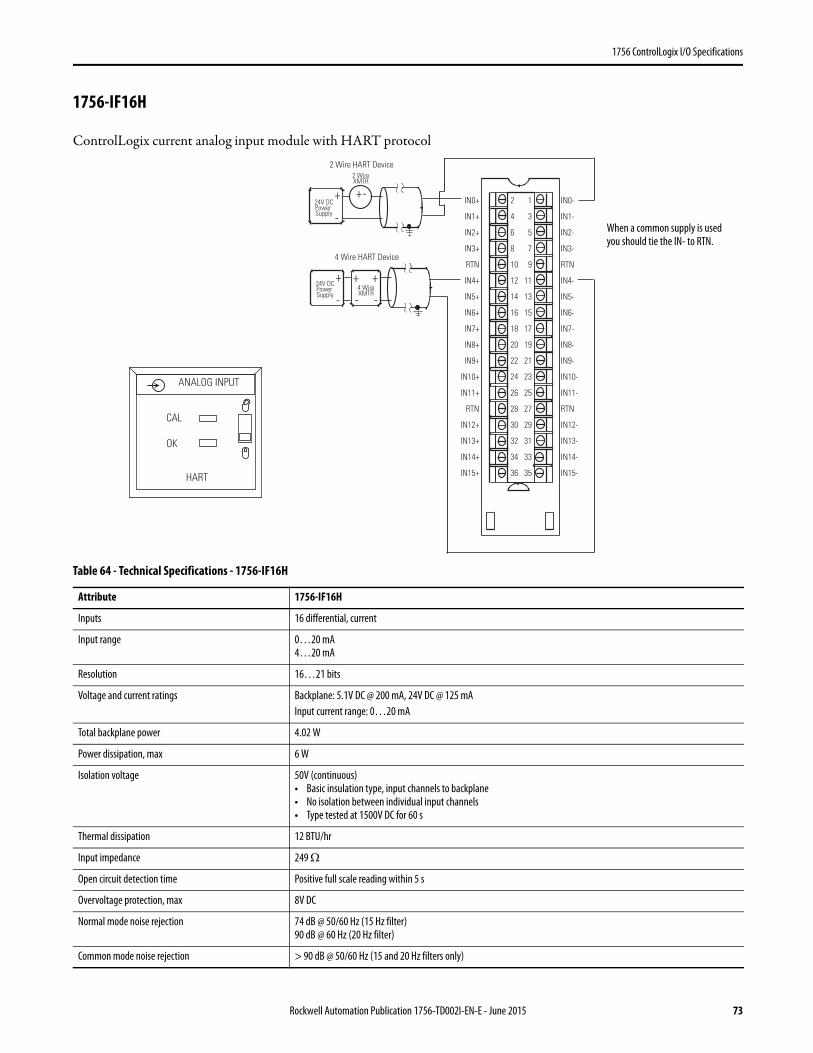
1756 ControlLogix I/O Specifications
1756-IF16H
ControlLogix current analog input module with HART protocol
Table 64 - Technical Specifications - 1756-IF16H
Attribute 1756-IF16H
Inputs 16 differential, current
Input range 0…20 mA4…20 mA
Resolution 16…21 bits
Voltage and current ratings Backplane: 5.1V DC @ 200 mA, 24V DC @ 125 mAInput current range: 0…20 mA
Total backplane power 4.02 W
Power dissipation, max 6 W
Isolation voltage 50V (continuous)• Basic insulation type, input channels to backplane• No isolation between individual input channels• Type tested at 1500V DC for 60 s
Thermal dissipation 12 BTU/hr
Input impedance 249 Ω
Open circuit detection time Positive full scale reading within 5 s
Overvoltage protection, max 8V DC
Normal mode noise rejection 74 dB @ 50/60 Hz (15 Hz filter)90 dB @ 60 Hz (20 Hz filter)
Common mode noise rejection > 90 dB @ 50/60 Hz (15 and 20 Hz filters only)
+
-
+
-
+
- -
+ -
2 Wire HART Device
4 Wire HART Device
IN0+
IN1+
IN2+
IN3+
RTN
IN4+
IN5+
IN6+
IN7+
IN8+
IN9+
IN10+
IN11+
RTN
IN12+
IN13+
IN14+
IN15+
IN0-
IN1-
IN2-
IN3-
RTN
IN4-
IN5-
IN6-
IN7-
IN8-
IN9-
IN10-
IN11-
RTN
IN12-
IN13-
IN14-
IN15-
2
4
6
8
10
12
14
16
18
20
22
24
26
28
30
32
34
36
1
3
5
7
9
11
13
15
17
19
21
23
25
27
29
31
33
35
24V DCPower Supply
24V DCPower Supply
4 WireXMTR
2 WireXMTR
+
When a common supply is used you should tie the IN- to RTN.
ANALOG INPUT
CAL
OK
HART
Rockwell Automation Publication 1756-TD002I-EN-E - June 2015 73
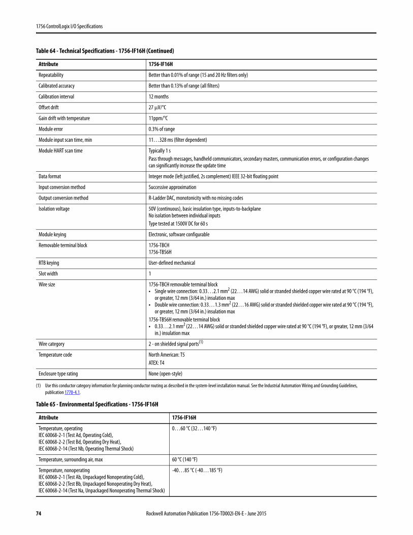
1756 ControlLogix I/O Specifications
Repeatability Better than 0.01% of range (15 and 20 Hz filters only)
Calibrated accuracy Better than 0.13% of range (all filters)
Calibration interval 12 months
Offset drift 27 μV/°C
Gain drift with temperature 11ppm/°C
Module error 0.3% of range
Module input scan time, min 11…328 ms (filter dependent)
Module HART scan time Typically 1 s Pass through messages, handheld communicators, secondary masters, communication errors, or configuration changes can significantly increase the update time
Data format Integer mode (left justified, 2s complement) IEEE 32-bit floating point
Input conversion method Successive approximation
Output conversion method R-Ladder DAC, monotonicity with no missing codes
Isolation voltage 50V (continuous), basic insulation type, inputs-to-backplaneNo isolation between individual inputsType tested at 1500V DC for 60 s
Module keying Electronic, software configurable
Removable terminal block 1756-TBCH1756-TBS6H
RTB keying User-defined mechanical
Slot width 1
Wire size 1756-TBCH removable terminal block• Single wire connection: 0.33…2.1 mm2 (22…14 AWG) solid or stranded shielded copper wire rated at 90 °C (194 °F),
or greater, 12 mm (3/64 in.) insulation max• Double wire connection: 0.33…1.3 mm2 (22…16 AWG) solid or stranded shielded copper wire rated at 90 °C (194 °F),
or greater, 12 mm (3/64 in.) insulation max1756-TBS6H removable terminal block• 0.33…2.1 mm2 (22…14 AWG) solid or stranded shielded copper wire rated at 90 °C (194 °F), or greater, 12 mm (3/64
in.) insulation max
Wire category 2 - on shielded signal ports(1)
Temperature code North American: T5ATEX: T4
Enclosure type rating None (open-style)
(1) Use this conductor category information for planning conductor routing as described in the system-level installation manual. See the Industrial Automation Wiring and Grounding Guidelines, publication 1770-4.1.
Table 65 - Environmental Specifications - 1756-IF16H
Attribute 1756-IF16H
Temperature, operatingIEC 60068-2-1 (Test Ad, Operating Cold),IEC 60068-2-2 (Test Bd, Operating Dry Heat),IEC 60068-2-14 (Test Nb, Operating Thermal Shock)
0…60 °C (32…140 °F)
Temperature, surrounding air, max 60 °C (140 °F)
Temperature, nonoperatingIEC 60068-2-1 (Test Ab, Unpackaged Nonoperating Cold),IEC 60068-2-2 (Test Bb, Unpackaged Nonoperating Dry Heat),IEC 60068-2-14 (Test Na, Unpackaged Nonoperating Thermal Shock)
-40…85 °C (-40…185 °F)
Table 64 - Technical Specifications - 1756-IF16H (Continued)
Attribute 1756-IF16H
74 Rockwell Automation Publication 1756-TD002I-EN-E - June 2015
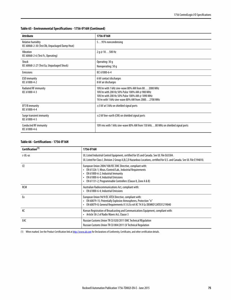
1756 ControlLogix I/O Specifications
Relative humidityIEC 60068-2-30 (Test Db, Unpackaged Damp Heat)
5…95% noncondensing
VibrationIEC 60068-2-6 (Test Fc, Operating)
2 g @ 10…500 Hz
ShockIEC 60068-2-27 (Test Ea, Unpackaged Shock)
Operating: 30 g Nonoperating: 50 g
Emissions IEC 61000-6-4
ESD immunityIEC 61000-4-2
6 kV contact discharges8 kV air discharges
Radiated RF immunityIEC 61000-4-3
10V/m with 1 kHz sine-wave 80% AM from 80… 2000 MHz10V/m with 200 Hz 50% Pulse 100% AM @ 900 MHz10V/m with 200 Hz 50% Pulse 100% AM @ 1890 MHz1V/m with 1 kHz sine-wave 80% AM from 2000…2700 MHz
EFT/B immunityIEC 61000-4-4
±3 kV at 5 kHz on shielded signal ports
Surge transient immunityIEC 61000-4-5
±2 kV line-earth (CM) on shielded signal ports
Conducted RF immunityIEC 61000-4-6
10V rms with 1 kHz sine-wave 80% AM from 150 kHz…80 MHz on shielded signal ports
Table 66 - Certifications - 1756-IF16H
Certification(1)
(1) When marked. See the Product Certification link at http://www.ab.com for Declarations of Conformity, Certificates, and other certification details.
1756-IF16H
c-UL-us UL Listed Industrial Control Equipment, certified for US and Canada. See UL File E65584.UL Listed for Class I, Division 2 Group A,B,C,D Hazardous Locations, certified for U.S. and Canada. See UL File E194810.
CE European Union 2004/108/IEC EMC Directive, compliant with:• EN 61326-1; Meas./Control/Lab., Industrial Requirements• EN 61000-6-2; Industrial Immunity• EN 61000-6-4; Industrial Emissions• EN 61131-2; Programmable Controllers (Clause 8, Zone A & B)
RCM Australian Radiocommunications Act, compliant with:• EN 61000-6-4; Industrial Emissions
Ex European Union 94/9/EC ATEX Directive, compliant with:• EN 60079-15; Potentially Explosive Atmospheres, Protection "n"• EN 60079-0; General Requirements II 3 G Ex nA IIC T4 X Gc DEMKO12ATEX1219040
KC Korean Registration of Broadcasting and Communications Equipment, compliant with:• Article 58-2 of Radio Waves Act, Clause 3
EAC Russian Customs Union TR CU 020/2011 EMC Technical REgulationRussian Customs Union TR CU 004/2011 LV Technical Regulation
Table 65 - Environmental Specifications - 1756-IF16H (Continued)
Attribute 1756-IF16H
Rockwell Automation Publication 1756-TD002I-EN-E - June 2015 75
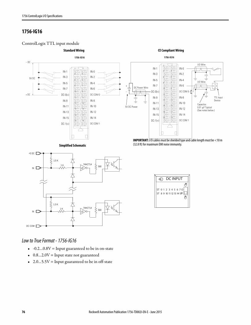
1756 ControlLogix I/O Specifications
1756-IG16
ControlLogix TTL input module
Low to True Format - 1756-IG16• -0.2…0.8V = Input guaranteed to be in on-state• 0.8…2.0V = Input state not guaranteed• 2.0…5.5V = Input guaranteed to be in off-state
1
3
5
7
9
19
17
15
13
11
2
4
6
8
10
20
18
16
14
12
IN-1
IN-3
IN-5
IN-7
DC-0(+)
IN-0
IN-2
IN-4
IN-6
DC COM 0
IN-9
IN-11
IN-13
IN-15
DC-1(+)
IN-8
IN-10
IN-12
IN-14
DC COM 1
5V DC
+ DC
– DC
1756-IG16
1
3
5
7
9
19
17
15
13
11
2
4
6
8
10
20
18
16
14
12
IN-1
IN-3
IN-5
IN-7
DC-0(+)
IN-0
IN-2
IN-4
IN-6
DC COM 0
IN-9
IN-11
IN-13
IN-15
DC-1(+)
IN-8
IN-10
IN-12
IN-14
DC COM 1
Capacitor0.01 μF Typical (See notes below.)
5V DC Power
DC Power Wire
I/O Wire
+
–
I/O Wire
TTL Input Device
+
–
1756-IG16
+5 DC
IN
1.5 K
1 K 74HCT14
1.5 K
1 K
560
74HCT14560
DC COM
IN
Standard Wiring CE Compliant Wiring
Simplified SchematicIMPORTANT: I/O cables must be shielded type and cable length must be <10 m (32.8 ft) for maximum EMI noise immunity.
DC INPUT
ST 0 1 2 3 4 5 6 7
ST 8 9 10 11 12 13 14 15
OK
76 Rockwell Automation Publication 1756-TD002I-EN-E - June 2015
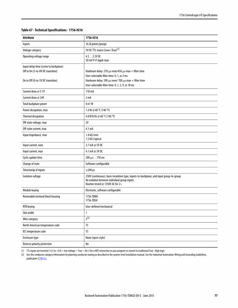
1756 ControlLogix I/O Specifications
Table 67 - Technical Specifications - 1756-IG16
Attribute 1756-IG16
Inputs 16 (8 points/group)
Voltage category 5V DC TTL source (Low=True)(1)
(1) TTL inputs are inverted (-0.2 to +0.8 = low voltage = True = On.) Use a NOT instruction in your program to convert to traditional True - High logic.
Operating voltage range 4.5…5.5V DC 50 mV P-P ripple max
Input delay time (screw to backplane)Off to On (5-to-0V DC transition)
On to Off (0-to-5V DC transition)
Hardware delay: 270 μs nom/450 μs max + filter timeUser-selectable filter time: 0, 1, or 2 msHardware delay: 390 μs nom/ 700 μs max + filter timeUser-selectable filter time: 0, 1, 2, 9, or 18 ms
Current draw @ 5.1V 110 mA
Current draw @ 24V 2 mA
Total backplane power 0.61 W
Power dissipation, max 1.4 W @ 60 °C (140 °F)
Thermal dissipation 4.8 BTU/hr @ 60 °C (140 °F)
Off-state voltage, max 2V
Off-state current, max 4.1 mA
Input impedance, max 1.4 kΩ min1.5 kΩ typical
Input current, nom 3.7 mA @ 5V DC
Input current, max 4.1 mA @ 5V DC
Cyclic update time 200 μs…750 ms
Change of state Software configurable
Timestamp of inputs ±200 μs
Isolation voltage 250V (continuous), basic insulation type, inputs-to-backplane, and input group-to-groupNo isolation between individual group inputsRoutine tested @ 1350V AC for 2 s
Module keying Electronic, software configurable
Removable terminal block housing 1756-TBNH1756-TBSH
RTB keying User-defined mechanical
Slot width 1
Wire category 2(2)
(2) Use this conductor category information for planning conductor routing as described in the system-level installation manual. See the Industrial Automation Wiring and Grounding Guidelines, publication 1770-4.1.
North American temperature code T5
IEC temperature code T5
Enclosure type None (open-style)
Reverse polarity protection No
Rockwell Automation Publication 1756-TD002I-EN-E - June 2015 77

1756 ControlLogix I/O Specifications
Table 68 - Environmental Specifications - 1756-IG16
Attribute 1756-IG16
Temperature, operatingIEC 60068-2-1 (Test Ad, Operating Cold),IEC 60068-2-2 (Test Bd, Operating Dry Heat),IEC 60068-2-14 (Test Nb, Operating Thermal Shock)
0…60 °C (32…140 °F)
Temperature, surrounding air, max 60 °C (140 °F)
Temperature, nonoperatingIEC 60068-2-1 (Test Ab, Unpackaged Nonoperating Cold),IEC 60068-2-2 (Test Bb, Unpackaged Nonoperating Dry Heat),IEC 60068-2-14 (Test Na, Unpackaged Nonoperating Thermal Shock)
-40…85 °C (-40…185 °F)
Relative humidityIEC 60068-2-30 (Test Db, Unpackaged Damp Heat)
5…95% noncondensing
VibrationIEC 60068-2-6 (Test Fc, Operating)
2 g @ 10…500 Hz
Shock, operatingIEC 60068-2-27 (Test Ea, Unpackaged Shock)
30 g
Shock, nonoperatingIEC 60068-2-27 (Test Ea, Unpackaged Shock)
50 g
Emissions CISPR 11, Class A
ESD immunityIEC 61000-4-2
6 kV contact discharges8 kV air discharges
Radiated RF immunityIEC 61000-4-3
10V/m with 1 kHz sine-wave 80% AM from 80… 2000 MHz10V/m with 200 Hz 50% Pulse 100% AM @ 900 MHz10V/m with 200 Hz 50% Pulse 100% AM @ 1890 MHz3V/m with 1 kHz sine-wave 80% AM from 2000…2700 MHz
EFT/B immunityIEC 61000-4-4
±1 kV at 5 kHz on signal ports
Conducted RF immunityIEC 61000-4-6
10V rms with 1 kHz sine-wave 80% AM from 150 kHz…80 MHz
Table 69 - Certifications - 1756-IG16
Certification(1)
(1) When marked. See the Product Certification link at http://www.ab.com for Declarations of Conformity, Certificates, and other certification details.
1756-IG16
UL UL Listed Industrial Control Equipment. See UL File E65584.
CSA CSA Certified Process Control Equipment. See CSA File LR54689C.CSA Certified Process Control Equipment for Class I, Division 2 Group A,B,C,D Hazardous Locations. See CSA File LR69960C.
CE European Union 2004/108/IEC EMC Directive, compliant with:• EN 61326-1; Meas./Control/Lab., Industrial Requirements• EN 61000-6-2; Industrial Immunity• EN 61000-6-4; Industrial Emissions• EN 61131-2; Programmable Controllers (Clause 8, Zone A & B)European Union 2006/95/EC LVD, compliant with:EN 61131-2; Programmable Controllers (Clause 11)
C-Tick Australian Radiocommunications Act, compliant with:AS/NZS CISPR 11; Industrial Emissions
Ex European Union 94/9/EC ATEX Directive, compliant with:• EN 60079-15; Potentially Explosive Atmospheres, Protection "n"• EN 60079-0; General Requirements II 3 G Ex nA IIC T5 X Gc
KC Korean Registration of Broadcasting and Communications Equipment, compliant with:Article 58-2 of Radio Waves Act, Clause 3
78 Rockwell Automation Publication 1756-TD002I-EN-E - June 2015

1756 ControlLogix I/O Specifications
1756-IH16I
ControlLogix 125V DC isolated input module
Table 70 - Technical Specifications - 1756-IH16I
Attribute 1756-IH16I
Inputs 16 individually isolated
Voltage category 125V DC sink/source
Operating voltage range 90…146V DC(1)
Input voltage, nom 125V DC
Input delay time (screw to backplane)Off to On
On to Off
Hardware delay: 2 ms max + filter timeUser-selectable filter time: 0, 1, or 2 msHardware delay: 6 max + filter timeUser-selectable filter time: 0, 1, 2, 9, or 18 ms
Current draw @ 5.1V 125 mA
Current draw @ 24V 3 mA
Total backplane power 0.71 W
Power dissipation, max 5 W @ 60 °C (140 °F)
Thermal dissipation 17.05 BTU/hr
Off-state voltage, max 20V DC
12
34
56
78
910
1112
1314
1516
1718
1920
2122
2324
2526
2728
2930
3132
3334
3536
Nonisolated Wiring
IsolatedWiring
Daisy Chain to Other RTBs
DC (-)
Jumper Bar (Cut to Length)
)+( 7-CD)-( 7-CD
DC (+)
DC-0 (+)
DC-3 (+)
DC-0 (-)
DC-3 (-)
IN-0
IN-1IN-2
IN-3
IN-8
IN-4IN-5IN-6
IN-7
Not Ysed
IN-9IN-10IN-11
IN-12IN-13IN-14IN-15
Not Used
GND-0
GND-1GND-2
GND-3
GND-8
GND-4GND-5GND-6
GND-7
Not Used
GND-9GND-10GND-11GND-12GND-13GND-14GND-15
GND-15
ControlLogix Backplane Interface
Simplified Schematic
Display
GND-0
IN-0
GND
+5V
Additional jumper bars are availableas cat. no. 1756-JMPR.
DC INPUT
ST 0 1 2 3 4 5 6 7
ST 8 9 10 11 12 13 14 15
OK
12
34
56
78
910
1112
1314
1516
1718
1920
2122
2324
2526
2728
2930
3132
3334
3536
Nonisolated Wiring
IsolatedWiring
Daisy Chain to Other RTBs
DC (-)
Jumper Bar (Cut to Length)
)+( 7-CD)-( 7-CD
DC (+)
DC-0 (+)
DC-3 (+)
DC-0 (-)
DC-3 (-)
IN-0
IN-1IN-2
IN-3
IN-8
IN-4IN-5IN-6
IN-7
Not Ysed
IN-9IN-10IN-11
IN-12IN-13IN-14IN-15
Not Used
GND-0
GND-1GND-2
GND-3
GND-8
GND-4GND-5GND-6
GND-7
Not Used
GND-9GND-10GND-11GND-12GND-13GND-14GND-15
GND-15
1756-IH161
Rockwell Automation Publication 1756-TD002I-EN-E - June 2015 79

1756 ControlLogix I/O Specifications
Off-state current, max 0.8 mA
On-state current, min 1 mA @ 90V DC
On-state current, max 3 mA @ 146V DC
On-state voltageDerated as follows
90…146V DC90…146V DC @ 50 °C (122 °F), 12 Channels ON90…132V DC @ 55 °C (131 °F), 14 Channels ON90…125V DC @ 60 °C (140 °F), 16 Channels ON90…146V DC @ 30 °C (86 °F), 16 Channels ON
Inrush current, max 250 mA
Input impedance, max 48.67 kΩ @ 146V DC
Cyclic update time 200 μs…750 ms
Change of state Software configurable
Timestamp of inputs ±200 μs
Isolation voltage 250V (continuous), basic insulation type, inputs-to-backplane, and input-to-inputRoutine tested @ 1350V AC for 2 s
Module keying Electronic, software configurable
Removable terminal block housing 1756-TBCH1756-TBS6H
RTB keying User-defined mechanical
Slot width 1
Wire category 1(2)
North American temperature code T4
Enclosure type None (open-style)
Reverse polarity protection Yes
(1) UL certification for 125V nominal. Rockwell Automation specified to the following:90…146V DC @ 50 °C (122 °F),12 channels on90…132V DC @ 55 °C (131 °F), 14 channels on90…125V DC @ 60 °C (140 °F), 16 channels on90…146V DC @ 30 °C (86 °F), 16 channels on.
(2) Use this conductor category information for planning conductor routing as described in the system-level installation manual. See the Industrial Automation Wiring and Grounding Guidelines, publication 1770-4.1.
Table 71 - Environmental Specifications - 1756-IH16I
Attribute 1756-IH16I
Temperature, operatingIEC 60068-2-1 (Test Ad, Operating Cold),IEC 60068-2-2 (Test Bd, Operating Dry Heat),IEC 60068-2-14 (Test Nb, Operating Thermal Shock)
0…60 °C (32…140 °F)
Temperature, surrounding air, max 60 °C (140 °F)
Temperature, nonoperatingIEC 60068-2-1 (Test Ab, Unpackaged Nonoperating Cold),IEC 60068-2-2 (Test Bb, Unpackaged Nonoperating Dry Heat),IEC 60068-2-14 (Test Na, Unpackaged Nonoperating Thermal Shock)
-40…85 °C (-40…185 °F)
Relative humidityIEC 60068-2-30 (Test Db, Unpackaged Damp Heat)
5…95% noncondensing
Table 70 - Technical Specifications - 1756-IH16I (Continued)
Attribute 1756-IH16I
80 Rockwell Automation Publication 1756-TD002I-EN-E - June 2015
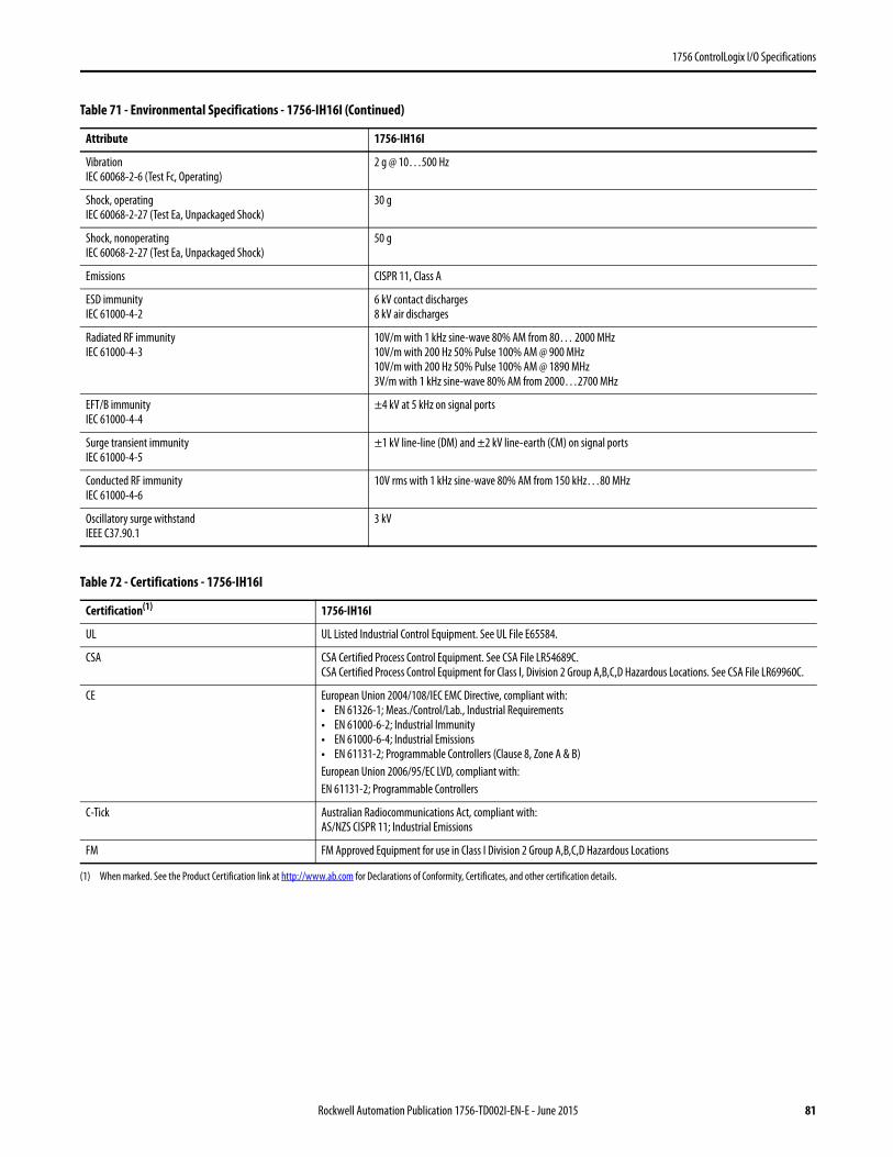
1756 ControlLogix I/O Specifications
VibrationIEC 60068-2-6 (Test Fc, Operating)
2 g @ 10…500 Hz
Shock, operatingIEC 60068-2-27 (Test Ea, Unpackaged Shock)
30 g
Shock, nonoperatingIEC 60068-2-27 (Test Ea, Unpackaged Shock)
50 g
Emissions CISPR 11, Class A
ESD immunityIEC 61000-4-2
6 kV contact discharges8 kV air discharges
Radiated RF immunityIEC 61000-4-3
10V/m with 1 kHz sine-wave 80% AM from 80… 2000 MHz10V/m with 200 Hz 50% Pulse 100% AM @ 900 MHz10V/m with 200 Hz 50% Pulse 100% AM @ 1890 MHz3V/m with 1 kHz sine-wave 80% AM from 2000…2700 MHz
EFT/B immunityIEC 61000-4-4
±4 kV at 5 kHz on signal ports
Surge transient immunityIEC 61000-4-5
±1 kV line-line (DM) and ±2 kV line-earth (CM) on signal ports
Conducted RF immunityIEC 61000-4-6
10V rms with 1 kHz sine-wave 80% AM from 150 kHz…80 MHz
Oscillatory surge withstandIEEE C37.90.1
3 kV
Table 72 - Certifications - 1756-IH16I
Certification(1)
(1) When marked. See the Product Certification link at http://www.ab.com for Declarations of Conformity, Certificates, and other certification details.
1756-IH16I
UL UL Listed Industrial Control Equipment. See UL File E65584.
CSA CSA Certified Process Control Equipment. See CSA File LR54689C.CSA Certified Process Control Equipment for Class I, Division 2 Group A,B,C,D Hazardous Locations. See CSA File LR69960C.
CE European Union 2004/108/IEC EMC Directive, compliant with:• EN 61326-1; Meas./Control/Lab., Industrial Requirements• EN 61000-6-2; Industrial Immunity• EN 61000-6-4; Industrial Emissions• EN 61131-2; Programmable Controllers (Clause 8, Zone A & B)European Union 2006/95/EC LVD, compliant with:EN 61131-2; Programmable Controllers
C-Tick Australian Radiocommunications Act, compliant with:AS/NZS CISPR 11; Industrial Emissions
FM FM Approved Equipment for use in Class I Division 2 Group A,B,C,D Hazardous Locations
Table 71 - Environmental Specifications - 1756-IH16I (Continued)
Attribute 1756-IH16I
Rockwell Automation Publication 1756-TD002I-EN-E - June 2015 81
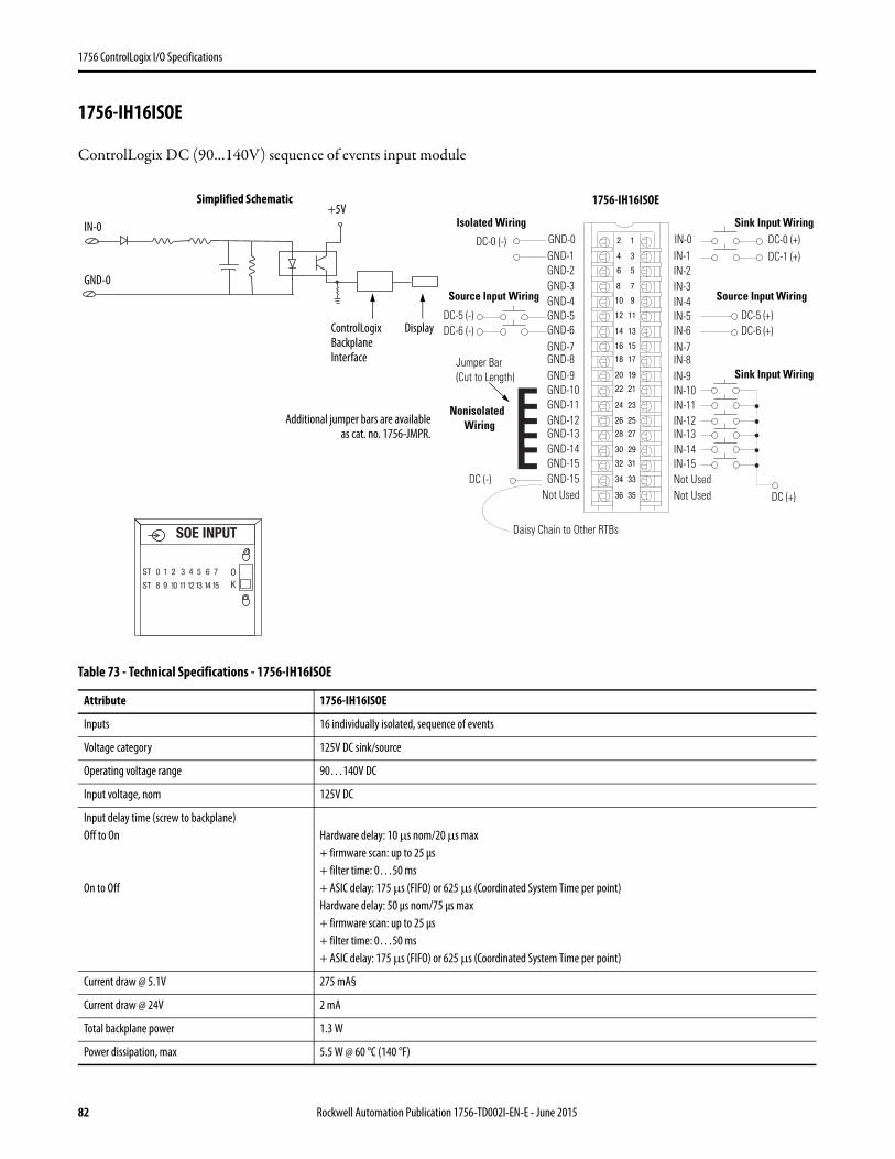
1756 ControlLogix I/O Specifications
1756-IH16ISOE
ControlLogix DC (90…140V) sequence of events input module
Table 73 - Technical Specifications - 1756-IH16ISOE
Attribute 1756-IH16ISOE
Inputs 16 individually isolated, sequence of events
Voltage category 125V DC sink/source
Operating voltage range 90…140V DC
Input voltage, nom 125V DC
Input delay time (screw to backplane)Off to On
On to Off
Hardware delay: 10 μs nom/20 μs max+ firmware scan: up to 25 μs+ filter time: 0…50 ms+ ASIC delay: 175 μs (FIFO) or 625 μs (Coordinated System Time per point)Hardware delay: 50 μs nom/75 μs max+ firmware scan: up to 25 μs+ filter time: 0…50 ms+ ASIC delay: 175 μs (FIFO) or 625 μs (Coordinated System Time per point)
Current draw @ 5.1V 275 mA§
Current draw @ 24V 2 mA
Total backplane power 1.3 W
Power dissipation, max 5.5 W @ 60 °C (140 °F)
12
34
56
78
910
1112
1314
1516
1718
1920
2122
2324
2526
2728
2930
3132
3334
3536
Nonisolated Wiring
Isolated Wiring
Daisy Chain to Other RTBs
DC (-)
Jumper Bar (Cut to Length)
)+( 6-CD)-( 6-CD
DC (+)
DC-0 (+)DC-1 (+)
DC-0 (-)
DC-5 (-)
IN-0IN-1IN-2IN-3
IN-8
IN-4IN-5IN-6IN-7
Not Used
IN-9IN-10IN-11IN-12IN-13IN-14IN-15Not Used
GND-0GND-1GND-2GND-3
GND-8
GND-4GND-5GND-6GND-7
Not Used
GND-9GND-10GND-11GND-12GND-13GND-14GND-15GND-15
DC-5 (+)
Sink Input Wiring
Source Input WiringSource Input Wiring
Sink Input Wiring
Simplified Schematic
ControlLogix Backplane Interface
IN-0
GND-0
Display
+5V
Additional jumper bars are availableas cat. no. 1756-JMPR.
SOE INPUT
ST 0 1 2 3 4 5 6 7
ST 8 9 10 11 12 13 14 15
OK
1756-IH16ISOE
82 Rockwell Automation Publication 1756-TD002I-EN-E - June 2015
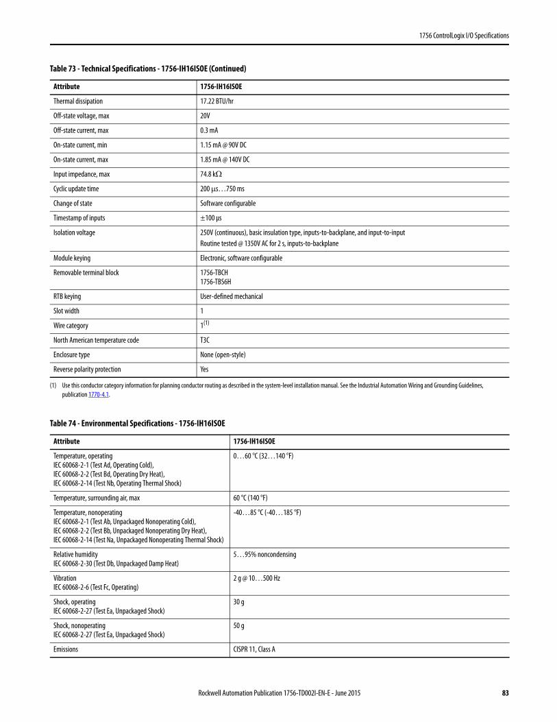
1756 ControlLogix I/O Specifications
Thermal dissipation 17.22 BTU/hr
Off-state voltage, max 20V
Off-state current, max 0.3 mA
On-state current, min 1.15 mA @ 90V DC
On-state current, max 1.85 mA @ 140V DC
Input impedance, max 74.8 kΩ
Cyclic update time 200 μs…750 ms
Change of state Software configurable
Timestamp of inputs ±100 μs
Isolation voltage 250V (continuous), basic insulation type, inputs-to-backplane, and input-to-inputRoutine tested @ 1350V AC for 2 s, inputs-to-backplane
Module keying Electronic, software configurable
Removable terminal block 1756-TBCH1756-TBS6H
RTB keying User-defined mechanical
Slot width 1
Wire category 1(1)
North American temperature code T3C
Enclosure type None (open-style)
Reverse polarity protection Yes
(1) Use this conductor category information for planning conductor routing as described in the system-level installation manual. See the Industrial Automation Wiring and Grounding Guidelines, publication 1770-4.1.
Table 74 - Environmental Specifications - 1756-IH16ISOE
Attribute 1756-IH16ISOE
Temperature, operatingIEC 60068-2-1 (Test Ad, Operating Cold),IEC 60068-2-2 (Test Bd, Operating Dry Heat),IEC 60068-2-14 (Test Nb, Operating Thermal Shock)
0…60 °C (32…140 °F)
Temperature, surrounding air, max 60 °C (140 °F)
Temperature, nonoperatingIEC 60068-2-1 (Test Ab, Unpackaged Nonoperating Cold),IEC 60068-2-2 (Test Bb, Unpackaged Nonoperating Dry Heat),IEC 60068-2-14 (Test Na, Unpackaged Nonoperating Thermal Shock)
-40…85 °C (-40…185 °F)
Relative humidityIEC 60068-2-30 (Test Db, Unpackaged Damp Heat)
5…95% noncondensing
VibrationIEC 60068-2-6 (Test Fc, Operating)
2 g @ 10…500 Hz
Shock, operatingIEC 60068-2-27 (Test Ea, Unpackaged Shock)
30 g
Shock, nonoperatingIEC 60068-2-27 (Test Ea, Unpackaged Shock)
50 g
Emissions CISPR 11, Class A
Table 73 - Technical Specifications - 1756-IH16ISOE (Continued)
Attribute 1756-IH16ISOE
Rockwell Automation Publication 1756-TD002I-EN-E - June 2015 83

1756 ControlLogix I/O Specifications
ESD immunityIEC 61000-4-2
6 kV contact discharges8 kV air discharges
Radiated RF immunityIEC 61000-4-3
10V/m with 1 kHz sine-wave 80% AM from 80… 2000 MHz10V/m with 200 Hz 50% Pulse 100% AM @ 900 MHz10V/m with 200 Hz 50% Pulse 100% AM @ 1890 MHz3V/m with 1 kHz sine-wave 80% AM from 2000…2700 MHz
EFT/B immunityIEC 61000-4-4
±4 kV at 5 kHz on signal ports
Surge transient immunityIEC 61000-4-5
±1 kV line-line (DM) and ±2 kV line-earth (CM) on signal ports
Conducted RF immunityIEC 61000-4-6
10V rms with 1 kHz sine-wave 80% AM from 150 kHz…80 MHz
Oscillatory surge withstandIEEE C37.90.1
3 kV
Table 75 - Certifications - 1756-IH16ISOE
Certification(1)
(1) When marked. See the Product Certification link at http://www.ab.com for Declarations of Conformity, Certificates, and other certification details.
1756-IH16ISOE
UL UL Listed Industrial Control Equipment. See UL File E65584.
CSA CSA Certified Process Control Equipment. See CSA File LR54689C.CSA Certified Process Control Equipment for Class I, Division 2 Group A,B,C,D Hazardous Locations. See CSA File LR69960C.
CE European Union 2004/108/IEC EMC Directive, compliant with:• EN 61326-1; Meas./Control/Lab., Industrial Requirements• EN 61000-6-2; Industrial Immunity• EN 61000-6-4; Industrial Emissions• EN 61131-2; Programmable Controllers (Clause 8, Zone A & B)European Union 2006/95/EC LVD, compliant with:EN 61131-2; Programmable Controllers (Clause 11)
C-Tick Australian Radiocommunications Act, compliant with:AS/NZS CISPR 11; Industrial Emissions
KC Korean Registration of Broadcasting and Communications Equipment, compliant with:Article 58-2 of Radio Waves Act, Clause 3
Table 74 - Environmental Specifications - 1756-IH16ISOE (Continued)
Attribute 1756-IH16ISOE
84 Rockwell Automation Publication 1756-TD002I-EN-E - June 2015
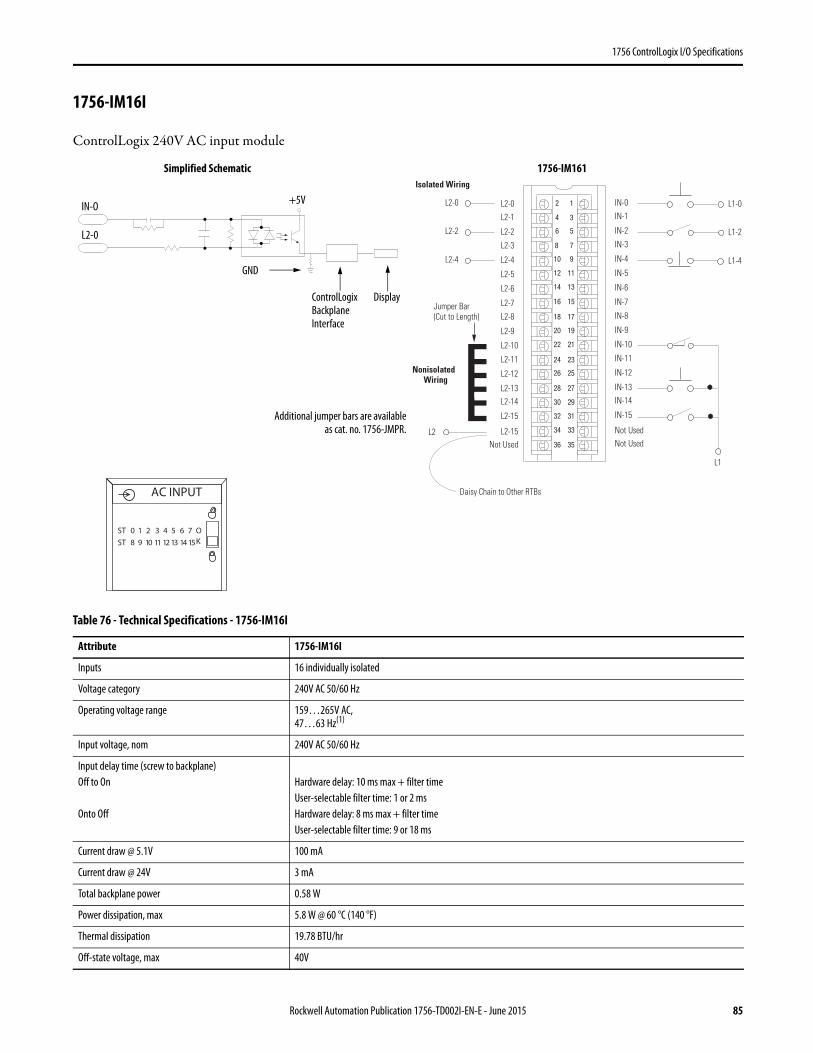
1756 ControlLogix I/O Specifications
1756-IM16I
ControlLogix 240V AC input module
Table 76 - Technical Specifications - 1756-IM16I
Attribute 1756-IM16I
Inputs 16 individually isolated
Voltage category 240V AC 50/60 Hz
Operating voltage range 159…265V AC,47…63 Hz(1)
Input voltage, nom 240V AC 50/60 Hz
Input delay time (screw to backplane)Off to On
Onto Off
Hardware delay: 10 ms max + filter timeUser-selectable filter time: 1 or 2 msHardware delay: 8 ms max + filter timeUser-selectable filter time: 9 or 18 ms
Current draw @ 5.1V 100 mA
Current draw @ 24V 3 mA
Total backplane power 0.58 W
Power dissipation, max 5.8 W @ 60 °C (140 °F)
Thermal dissipation 19.78 BTU/hr
Off-state voltage, max 40V
12
34
56
78
910
1112
1314
1516
1718
1920
2122
2324
2526
2728
2930
3132
3334
3536
Nonisolated Wiring
Isolated Wiring
Daisy Chain to Other RTBs
L2-0 L2-0L2-1
L2-2
L2-3
L2-8
L2-4
L2-5
L2-6
L2-7
Not Used
L2-9
L2-10
L2-11
L2-12
L2-13L2-14
L2-15
L2-15
IN-0IN-1
IN-2
IN-3
IN-8
IN-4
IN-5
IN-6
IN-7
Not Used
IN-9
IN-10
IN-11
IN-12
IN-13IN-14
IN-15
Not Used
L2-2
L2-4
L2
L1
L1-0
L1-2
L1-4
Jumper Bar (Cut to Length)
ControlLogix Backplane Interface
Simplified Schematic
Display
+5V
L2-0
IN-O
GND
Additional jumper bars are availableas cat. no. 1756-JMPR.
ST 0 1 2 3 4 5 6 7
ST 8 9 10 11 12 13 14 15
OK
AC INPUT
1756-IM161
Rockwell Automation Publication 1756-TD002I-EN-E - June 2015 85
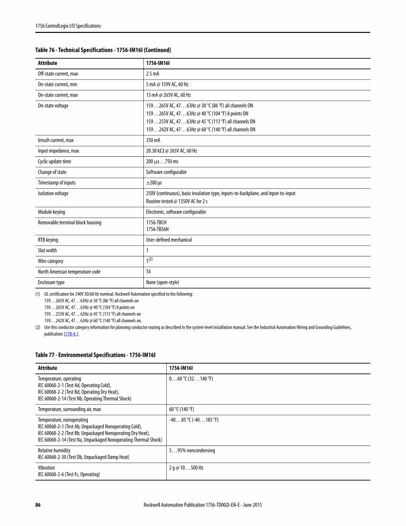
1756 ControlLogix I/O Specifications
Off-state current, max 2.5 mA
On-state current, min 5 mA @ 159V AC, 60 Hz
On-state current, max 13 mA @ 265V AC, 60 Hz
On-state voltage 159…265V AC, 47…63Hz @ 30 °C (86 °F) all channels ON159…265V AC, 47…63Hz @ 40 °C (104 °F) 8 points ON159…253V AC, 47…63Hz @ 45 °C (113 °F) all channels ON159…242V AC, 47…63Hz @ 60 °C (140 °F) all channels ON
Inrush current, max 250 mA
Input impedance, max 20.38 kΩ @ 265V AC, 60 Hz
Cyclic update time 200 μs…750 ms
Change of state Software configurable
Timestamp of inputs ±200 μs
Isolation voltage 250V (continuous), basic insulation type, inputs-to-backplane, and input-to-inputRoutine tested @ 1350V AC for 2 s
Module keying Electronic, software configurable
Removable terminal block housing 1756-TBCH1756-TBS6H
RTB keying User-defined mechanical
Slot width 1
Wire category 1(2)
North American temperature code T4
Enclosure type None (open-style)
(1) UL certification for 240V 50/60 Hz nominal. Rockwell Automation specified to the following:159…265V AC, 47…63Hz @ 30 °C (86 °F) all channels on159…265V AC, 47…63Hz @ 40 °C (104 °F) 8 points on159…253V AC, 47…63Hz @ 45 °C (113 °F) all channels on159…242V AC, 47…63Hz @ 60 °C (140 °F) all channels on.
(2) Use this conductor category information for planning conductor routing as described in the system-level installation manual. See the Industrial Automation Wiring and Grounding Guidelines, publication 1770-4.1.
Table 77 - Environmental Specifications - 1756-IM16I
Attribute 1756-IM16I
Temperature, operatingIEC 60068-2-1 (Test Ad, Operating Cold),IEC 60068-2-2 (Test Bd, Operating Dry Heat),IEC 60068-2-14 (Test Nb, Operating Thermal Shock)
0…60 °C (32…140 °F)
Temperature, surrounding air, max 60 °C (140 °F)
Temperature, nonoperatingIEC 60068-2-1 (Test Ab, Unpackaged Nonoperating Cold),IEC 60068-2-2 (Test Bb, Unpackaged Nonoperating Dry Heat),IEC 60068-2-14 (Test Na, Unpackaged Nonoperating Thermal Shock)
-40…85 °C (-40…185 °F)
Relative humidityIEC 60068-2-30 (Test Db, Unpackaged Damp Heat)
5…95% noncondensing
VibrationIEC 60068-2-6 (Test Fc, Operating)
2 g @ 10…500 Hz
Table 76 - Technical Specifications - 1756-IM16I (Continued)
Attribute 1756-IM16I
86 Rockwell Automation Publication 1756-TD002I-EN-E - June 2015
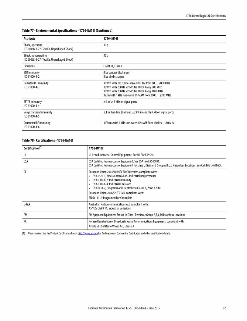
1756 ControlLogix I/O Specifications
Shock, operatingIEC 60068-2-27 (Test Ea, Unpackaged Shock)
30 g
Shock, nonoperatingIEC 60068-2-27 (Test Ea, Unpackaged Shock)
50 g
Emissions CISPR 11, Class A
ESD immunityIEC 61000-4-2
6 kV contact discharges8 kV air discharges
Radiated RF immunityIEC 61000-4-3
10V/m with 1 kHz sine-wave 80% AM from 80… 2000 MHz10V/m with 200 Hz 50% Pulse 100% AM @ 900 MHz10V/m with 200 Hz 50% Pulse 100% AM @ 1890 MHz3V/m with 1 kHz sine-wave 80% AM from 2000…2700 MHz
EFT/B immunityIEC 61000-4-4
±4 kV at 5 kHz on signal ports
Surge transient immunityIEC 61000-4-5
±1 kV line-line (DM) and ±2 kV line-earth (CM) on signal ports
Conducted RF immunityIEC 61000-4-6
10V rms with 1 kHz sine-wave 80% AM from 150 kHz…80 MHz
Table 78 - Certifications - 1756-IM16I
Certification(1)
(1) When marked. See the Product Certification link at http://www.ab.com for Declarations of Conformity, Certificates, and other certification details.
1756-IM16I
UL UL Listed Industrial Control Equipment. See UL File E65584.
CSA CSA Certified Process Control Equipment. See CSA File LR54689C.CSA Certified Process Control Equipment for Class I, Division 2 Group A,B,C,D Hazardous Locations. See CSA File LR69960C.
CE European Union 2004/108/IEC EMC Directive, compliant with:• EN 61326-1; Meas./Control/Lab., Industrial Requirements• EN 61000-6-2; Industrial Immunity• EN 61000-6-4; Industrial Emissions• EN 61131-2; Programmable Controllers (Clause 8, Zone A & B)European Union 2006/95/EC LVD, compliant with:EN 61131-2; Programmable Controllers
C-Tick Australian Radiocommunications Act, compliant with:AS/NZS CISPR 11; Industrial Emissions
FM FM Approved Equipment for use in Class I Division 2 Group A,B,C,D Hazardous Locations
KC Korean Registration of Broadcasting and Communications Equipment, compliant with:Article 58-2 of Radio Waves Act, Clause 3
Table 77 - Environmental Specifications - 1756-IM16I (Continued)
Attribute 1756-IM16I
Rockwell Automation Publication 1756-TD002I-EN-E - June 2015 87
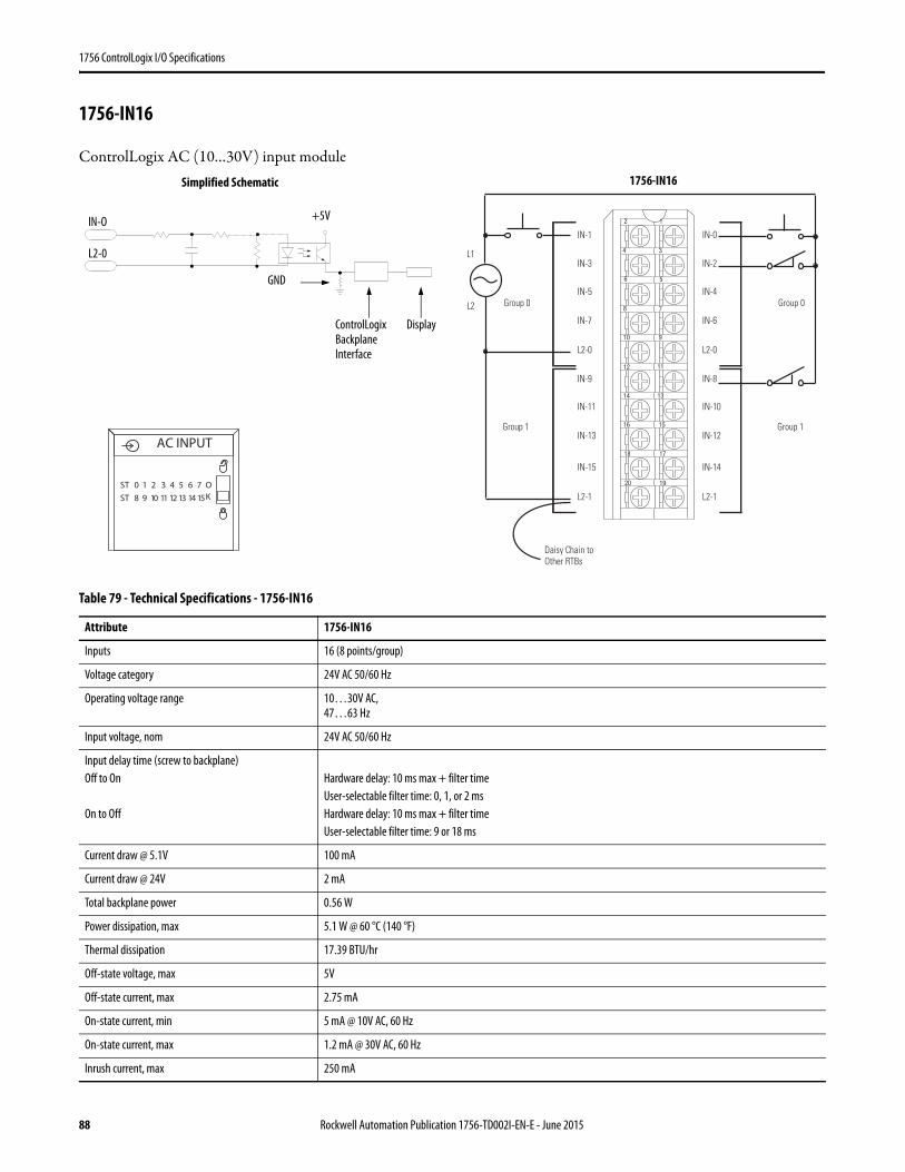
1756 ControlLogix I/O Specifications
1756-IN16
ControlLogix AC (10…30V) input module
Table 79 - Technical Specifications - 1756-IN16
Attribute 1756-IN16
Inputs 16 (8 points/group)
Voltage category 24V AC 50/60 Hz
Operating voltage range 10…30V AC,47…63 Hz
Input voltage, nom 24V AC 50/60 Hz
Input delay time (screw to backplane)Off to On
On to Off
Hardware delay: 10 ms max + filter timeUser-selectable filter time: 0, 1, or 2 msHardware delay: 10 ms max + filter timeUser-selectable filter time: 9 or 18 ms
Current draw @ 5.1V 100 mA
Current draw @ 24V 2 mA
Total backplane power 0.56 W
Power dissipation, max 5.1 W @ 60 °C (140 °F)
Thermal dissipation 17.39 BTU/hr
Off-state voltage, max 5V
Off-state current, max 2.75 mA
On-state current, min 5 mA @ 10V AC, 60 Hz
On-state current, max 1.2 mA @ 30V AC, 60 Hz
Inrush current, max 250 mA
12
34
56
78
910
1112
1314
1516
1718
1920
Daisy Chain to Other RTBs
Group 0Group 0
Group 1Group 1
IN-1
IN-3
IN-5
IN-7
L2-0
IN-9
IN-11
IN-13
IN-15
L2-1
IN-0
IN-2
IN-4
IN-6
L2-0
IN-8
IN-10
IN-12
IN-14
L2-1
L2
L1
ControlLogix Backplane Interface
Simplified Schematic
Display
+5V
L2-0
IN-O
GND
ST 0 1 2 3 4 5 6 7
ST 8 9 10 11 12 13 14 15
OK
AC INPUT
1756-IN16
88 Rockwell Automation Publication 1756-TD002I-EN-E - June 2015
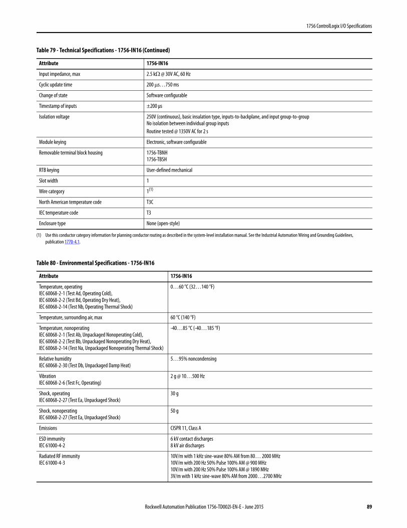
1756 ControlLogix I/O Specifications
Input impedance, max 2.5 kΩ @ 30V AC, 60 Hz
Cyclic update time 200 μs…750 ms
Change of state Software configurable
Timestamp of inputs ±200 μs
Isolation voltage 250V (continuous), basic insulation type, inputs-to-backplane, and input group-to-groupNo isolation between individual group inputsRoutine tested @ 1350V AC for 2 s
Module keying Electronic, software configurable
Removable terminal block housing 1756-TBNH1756-TBSH
RTB keying User-defined mechanical
Slot width 1
Wire category 1(1)
North American temperature code T3C
IEC temperature code T3
Enclosure type None (open-style)
(1) Use this conductor category information for planning conductor routing as described in the system-level installation manual. See the Industrial Automation Wiring and Grounding Guidelines, publication 1770-4.1.
Table 80 - Environmental Specifications - 1756-IN16
Attribute 1756-IN16
Temperature, operatingIEC 60068-2-1 (Test Ad, Operating Cold),IEC 60068-2-2 (Test Bd, Operating Dry Heat),IEC 60068-2-14 (Test Nb, Operating Thermal Shock)
0…60 °C (32…140 °F)
Temperature, surrounding air, max 60 °C (140 °F)
Temperature, nonoperatingIEC 60068-2-1 (Test Ab, Unpackaged Nonoperating Cold),IEC 60068-2-2 (Test Bb, Unpackaged Nonoperating Dry Heat),IEC 60068-2-14 (Test Na, Unpackaged Nonoperating Thermal Shock)
-40…85 °C (-40…185 °F)
Relative humidityIEC 60068-2-30 (Test Db, Unpackaged Damp Heat)
5…95% noncondensing
VibrationIEC 60068-2-6 (Test Fc, Operating)
2 g @ 10…500 Hz
Shock, operatingIEC 60068-2-27 (Test Ea, Unpackaged Shock)
30 g
Shock, nonoperatingIEC 60068-2-27 (Test Ea, Unpackaged Shock)
50 g
Emissions CISPR 11, Class A
ESD immunityIEC 61000-4-2
6 kV contact discharges8 kV air discharges
Radiated RF immunityIEC 61000-4-3
10V/m with 1 kHz sine-wave 80% AM from 80… 2000 MHz10V/m with 200 Hz 50% Pulse 100% AM @ 900 MHz10V/m with 200 Hz 50% Pulse 100% AM @ 1890 MHz3V/m with 1 kHz sine-wave 80% AM from 2000…2700 MHz
Table 79 - Technical Specifications - 1756-IN16 (Continued)
Attribute 1756-IN16
Rockwell Automation Publication 1756-TD002I-EN-E - June 2015 89

1756 ControlLogix I/O Specifications
EFT/B immunityIEC 61000-4-4
±4 kV at 5 kHz on signal ports
Surge transient immunityIEC 61000-4-5
±1 kV line-line (DM) and ±2 kV line-earth (CM) on signal ports
Conducted RF immunityIEC 61000-4-6
10V rms with 1 kHz sine-wave 80% AM from 150 kHz…80 MHz
Table 81 - Certifications - 1756-IN16
Certification(1)
(1) When marked. See the Product Certification link at http://www.ab.com for Declarations of Conformity, Certificates, and other certification details.
1756-IN16
UL UL Listed Industrial Control Equipment. See UL File E65584.
CSA CSA Certified Process Control Equipment. See CSA File LR54689C.CSA Certified Process Control Equipment for Class I, Division 2 Group A,B,C,D Hazardous Locations. See CSA File LR69960C.
CE European Union 2004/108/IEC EMC Directive, compliant with:• EN 61326-1; Meas./Control/Lab., Industrial Requirements• EN 61000-6-2; Industrial Immunity• EN 61000-6-4; Industrial Emissions• EN 61131-2; Programmable Controllers (Clause 8, Zone A & B)European Union 2006/95/EC LVD, compliant with:EN 61131-2; Programmable Controllers (Clause 11)
C-Tick Australian Radiocommunications Act, compliant with:AS/NZS CISPR 11; Industrial Emissions
Ex European Union 94/9/EC ATEX Directive, compliant with:• EN 60079-15; Potentially Explosive Atmospheres, Protection "n"• EN 60079-0; General Requirements II 3 G Ex nA IIC T3 X Gc
FM FM Approved Equipment for use in Class I Division 2 Group A,B,C,D Hazardous Locations
Table 80 - Environmental Specifications - 1756-IN16 (Continued)
Attribute 1756-IN16
90 Rockwell Automation Publication 1756-TD002I-EN-E - June 2015
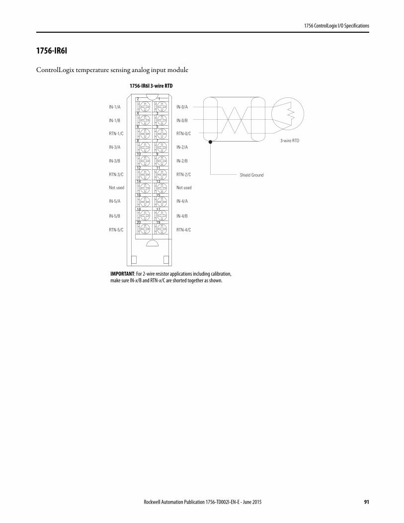
1756 ControlLogix I/O Specifications
1756-IR6I
ControlLogix temperature sensing analog input module
12
34
56
78
910
1112
1314
1516
1718
1920
3-wire RTD
Shield Ground
IN-1/A
IN-1/B
RTN-1/C
IN-3/A
IN-3/B
RTN-3/C
Not used
IN-5/A
IN-5/B
RTN-5/C
IN-0/A
IN-0/B
RTN-0/C
IN-2/A
IN-2/B
RTN-2/C
Not used
IN-4/A
IN-4/B
RTN-4/C
IMPORTANT: For 2-wire resistor applications including calibration, make sure IN-x/B and RTN-x/C are shorted together as shown.
1756-IR6I 3-wire RTD
Rockwell Automation Publication 1756-TD002I-EN-E - June 2015 91
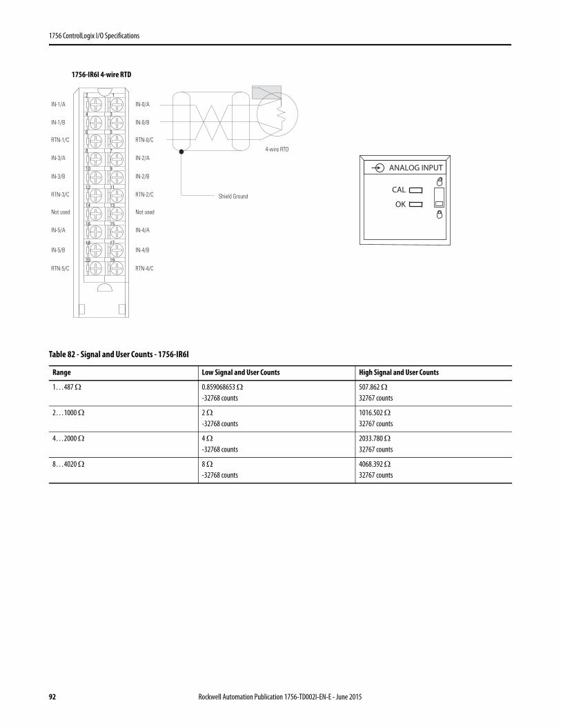
1756 ControlLogix I/O Specifications
Table 82 - Signal and User Counts - 1756-IR6I
Range Low Signal and User Counts High Signal and User Counts
1…487 Ω 0.859068653 Ω-32768 counts
507.862 Ω32767 counts
2…1000 Ω 2 Ω-32768 counts
1016.502 Ω32767 counts
4…2000 Ω 4 Ω-32768 counts
2033.780 Ω32767 counts
8…4020 Ω 8 Ω-32768 counts
4068.392 Ω32767 counts
12
34
56
78
910
1112
1314
1516
1718
1920
4-wire RTD
Shield Ground
IN-1/A
IN-1/B
RTN-1/C
IN-3/A
IN-3/B
RTN-3/C
Not used
IN-5/A
IN-5/B
RTN-5/C
IN-0/A
IN-0/B
RTN-0/C
IN-2/A
IN-2/B
RTN-2/C
Not used
IN-4/A
IN-4/B
RTN-4/C
ANALOG INPUT
CAL
OK
1756-IR6I 4-wire RTD
92 Rockwell Automation Publication 1756-TD002I-EN-E - June 2015
1756 ControlLogix I/O Specifications
Table 83 - Technical Specifications - 1756-IR6I
Attribute 1756-IR6I
Inputs 6 individually isolated RTD
Input range 1…487 Ω2…1000 Ω4…2000 Ω8…4000 Ω
Resolution 16 bits1…487 Ω: 7.7 mΩ/bit2…1000 Ω:15 mΩ/bit4…2000 Ω:30 mΩ/bit8…4020 Ω:60 mΩ/bit
Sensors supported 100, 200, 500, 1000 Ω Platinum, alpha=385100, 200, 500, 1000 Ω Platinum, alpha=3916120 Ω Nickel, alpha=672100, 120, 200, 500 Ω Nickel, alpha=61810 Ω Copper
Current draw @ 5.1V 250 mA
Current draw @ 24V 125 mA
Total backplane power 4.25 W
Power dissipation, max 4.3 W
Thermal dissipation 14.66 BTU/hr
Open circuit detection time Negative full scale reading within 5 s with any combination of lost wires, except input terminal A alone. If input terminal A is lost by itself, the module reads a positive full scale reading within 5 s
Overvoltage protection, max 24V AC/DC
Normal mode noise rejection 60 dB at 60 Hz(1)
Common mode noise rejection 120 dB @ 60 Hz100 dB @ 50 Hz
Channel bandwidth 15 Hz(1)
Settling time <80 ms to 5% of full scale(1)
Calibrated accuracy @ 25 °C Better than 0.1% of range
Calibration interval 6 months
Offset drift 10 MΩ/°C
Gain drift with temperature, nom 50 ppm/°C
Gain drift with temperature, max 90 ppm/°C
Module error 0.54% of range
Module scan time 25 ms min floating point (ohms)50 ms min floating point (temperature)10 ms min integer (ohms)(1)
Data format Integer mode (left justified, 2s complement) IEEE 32-bit floating point
Module conversion method Sigma-Delta
Isolation voltage 250V (continuous), basic insulation type, input channels-to-backplane, and input channel-to-channelRoutine tested at 1350V AC for 2 s
Module keying Electronic, software configurable
Removable terminal block 1756-TBNH1756-TBSH
RTB keying User-defined mechanical
Slot width 1
Rockwell Automation Publication 1756-TD002I-EN-E - June 2015 93
1756 ControlLogix I/O Specifications
Wire category 2(2)
North American temperature code T4A
IEC temperature code T4
Enclosure type None (open-style)
(1) Notch filter dependent.(2) Use this conductor category information for planning conductor routing as described in the system-level installation manual. See the Industrial Automation Wiring and Grounding Guidelines,
publication 1770-4.1.
Table 84 - Environmental Specifications - 1756-IR6I
Attribute 1756-IR6I
Temperature, operatingIEC 60068-2-1 (Test Ad, Operating Cold),IEC 60068-2-2 (Test Bd, Operating Dry Heat),IEC 60068-2-14 (Test Nb, Operating Thermal Shock)
0…60 °C (32…140 °F)
Temperature, surrounding air, max 60 °C (140 °F)
Temperature, nonoperatingIEC 60068-2-1 (Test Ab, Unpackaged Nonoperating Cold),IEC 60068-2-2 (Test Bb, Unpackaged Nonoperating Dry Heat),IEC 60068-2-14 (Test Na, Unpackaged Nonoperating Thermal Shock)
-40…85 °C (-40…185 °F)
Relative humidityIEC 60068-2-30 (Test Db, Unpackaged Damp Heat)
5…95% noncondensing
VibrationIEC 60068-2-6 (Test Fc, Operating)
2 g @ 10…500 Hz
Shock, operatingIEC 60068-2-27 (Test Ea, Unpackaged Shock)
30 g
Shock, nonoperatingIEC 60068-2-27 (Test Ea, Unpackaged Shock)
50 g
Emissions CISPR 11, Class A
ESD immunityIEC 61000-4-2
6 kV contact discharges8 kV air discharges
Radiated RF immunityIEC 61000-4-3
10V/m with 1 kHz sine-wave 80% AM from 80… 2000 MHz10V/m with 200 Hz 50% Pulse 100% AM @ 900 MHz10V/m with 200 Hz 50% Pulse 100% AM @ 1890 MHz3V/m with 1 kHz sine-wave 80% AM from 2000…2700 MHz
EFT/B immunityIEC 61000-4-4
±2 kV at 5 kHz on shielded signal ports
Surge transient immunityIEC 61000-4-5
±2 kV line-earth (CM) on shielded signal ports
Conducted RF immunityIEC 61000-4-6
10V rms with 1 kHz sine-wave 80% AM from 150 kHz…80 MHz on shielded signal ports
Table 83 - Technical Specifications - 1756-IR6I (Continued)
Attribute 1756-IR6I
94 Rockwell Automation Publication 1756-TD002I-EN-E - June 2015

1756 ControlLogix I/O Specifications
Table 85 - Certifications - 1756-IR6I
Certification(1)
(1) When marked. See the Product Certification link at http://www.ab.com for Declarations of Conformity, Certificates, and other certification details.
1756-IR6I
UL UL Listed Industrial Control Equipment. See UL File E65584.
CSA CSA Certified Process Control Equipment. See CSA File LR54689C.CSA Certified Process Control Equipment for Class I, Division 2 Group A,B,C,D Hazardous Locations. See CSA File LR69960C.
CE European Union 2004/108/IEC EMC Directive, compliant with:• EN 61326-1; Meas./Control/Lab., Industrial Requirements• EN 61000-6-2; Industrial Immunity• EN 61000-6-4; Industrial Emissions• EN 61131-2; Programmable Controllers (Clause 8, Zone A & B)European Union 2006/95/EC LVD, compliant with:EN 61131-2; Programmable Controllers (Clause 11)
C-Tick Australian Radiocommunications Act, compliant with:AS/NZS CISPR 11; Industrial Emissions
Ex European Union 94/9/EC ATEX Directive, compliant with:• EN 60079-15; Potentially Explosive Atmospheres, Protection "n"• EN 60079-0; General Requirements II 3 G Ex nA IIC T4 X Gc
FM FM Approved Equipment for use in Class I Division 2 Group A,B,C,D Hazardous Locations
KC Korean Registration of Broadcasting and Communications Equipment, compliant with:Article 58-2 of Radio Waves Act, Clause 3
Rockwell Automation Publication 1756-TD002I-EN-E - June 2015 95

1756 ControlLogix I/O Specifications
1756-IRT8I
ControlLogix isolated RTD/Thermocouple analog input module.
1
3
5
7
01 9
1112
41 31
61 51
81 71
02 91
22 12
42 32
62 52
82 72
03 92
23 13
33
63 53
2
34
8
6
4
1
3
5
7
01 9
1112
41 31
61 51
81 71
02 91
22 12
42 32
62 52
82 72
03 92
23 13
33
63 53
2
34
8
6
4
CJC 0IN_0(-)/BIN_0/RTD CIN_1(-)/B
IN_1/RTD C
IN_2(-)/BIN_2/RTD CIN_3(-)/B
IMPORTANT: Remember the following: • If separate power sources are used, do
not exceed the specific isolation voltage as listed in the specifications.
• Terminals 1, 2, 35, and 36 are not used in RTD applications.
• For 2-wire resistor applications including calibration, make sure IN_x(-)/B and IN_x/RTD C are shorted together.
IN_3/RTD CIN_4(-)/BIN_4/RTD CIN_5(-)/B
IN_5/RTD C
IN_6(-)/BIN_6/RTD CIN_7(-)/BIN_7/RTD CCJC 1
CJC 0IN_0(+)/AIN_0/RTD DIN_1(+)/A
IN_1/RTD D
IN_2(+)/AIN_2/RTD DIN_3(+)/AIN_3/RTD DIN_4(+)/AIN_4/RTD DIN_5(+)/A
IN_5/RTD D
IN_6(+)/AIN_6/RTD DIN_7(+)/AIN_7/RTD DCJC1
Shield Ground
3-wire RTD
1756-IRT8I Module Wiring Diagram - 3-wire RTD Input
IMPORTANT: Remember the following:• If separate power sources are used,
do not exceed the specific isolation voltage as listed in the specifications.
• Terminals 1, 2, 35, and 36 are not used in RTD applications.
Shield Ground
4-wire RTD
CJC 0IN_0(-)/BIN_0/RTD CIN_1(-)/B
IN_1/RTD C
IN_2(-)/BIN_2/RTD CIN_3(-)/BIN_3/RTD CIN_4(-)/BIN_4/RTD CIN_5(-)/B
IN_5/RTD C
IN_6(-)/BIN_6/RTD CIN_7(-)/BIN_7/RTD CCJC 1
CJC 0IN_0(+)/AIN_0/RTD DIN_1(+)/A
IN_1/RTD D
IN_2(+)/AIN_2/RTD DIN_3(+)/AIN_3/RTD DIN_4(+)/AIN_4/RTD DIN_5(+)/A
IN_5/RTD D
IN_6(+)/AIN_6/RTD DIN_7(+)/AIN_7/RTD DCJC1
1756-IRT8I Module Wiring Diagram - 4-wire RTD Input
96 Rockwell Automation Publication 1756-TD002I-EN-E - June 2015
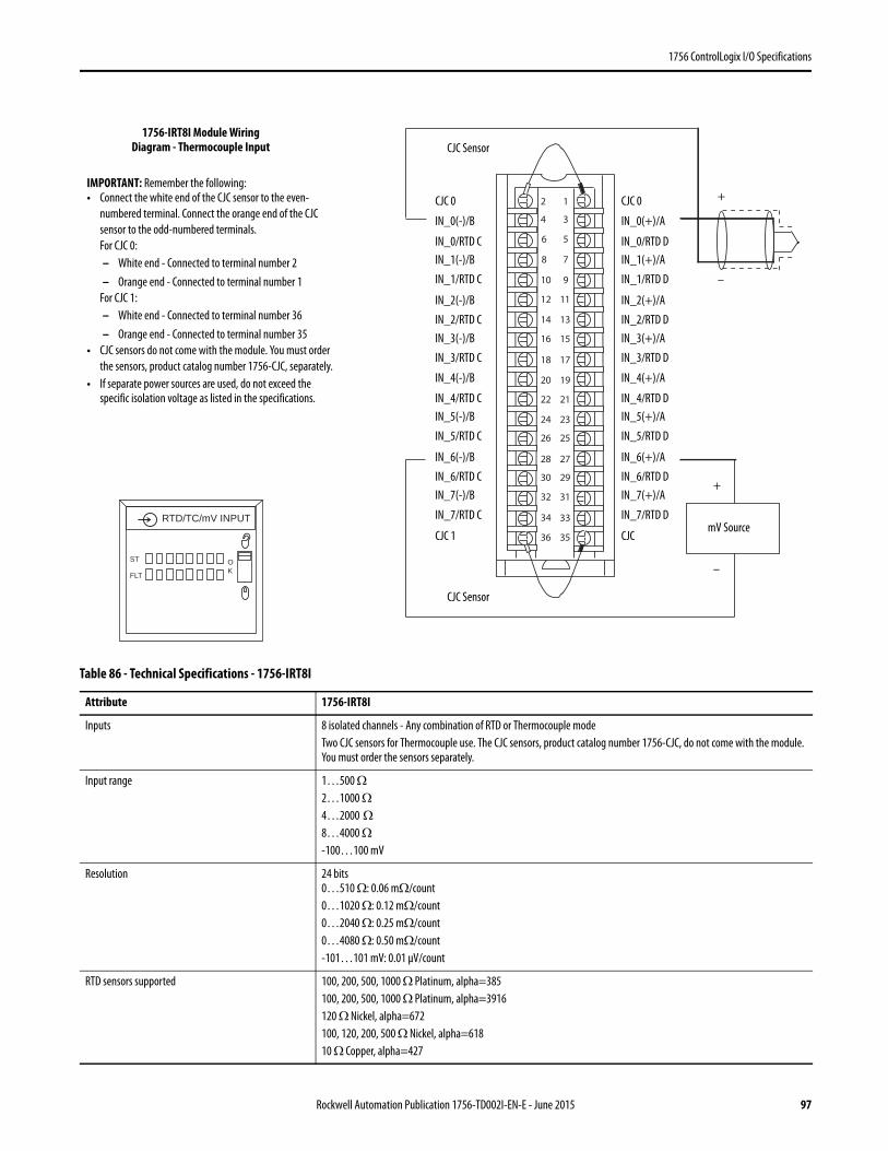
1756 ControlLogix I/O Specifications
Table 86 - Technical Specifications - 1756-IRT8I
Attribute 1756-IRT8I
Inputs 8 isolated channels - Any combination of RTD or Thermocouple modeTwo CJC sensors for Thermocouple use. The CJC sensors, product catalog number 1756-CJC, do not come with the module. You must order the sensors separately.
Input range 1…500 Ω2…1000 Ω4…2000 Ω
8…4000 Ω -100…100 mV
Resolution 24 bits0…510 Ω: 0.06 mΩ/count0…1020 Ω: 0.12 mΩ/count0…2040 Ω: 0.25 mΩ/count0…4080 Ω: 0.50 mΩ/count-101…101 mV: 0.01 μV/count
RTD sensors supported 100, 200, 500, 1000 Ω Platinum, alpha=385100, 200, 500, 1000 Ω Platinum, alpha=3916120 Ω Nickel, alpha=672100, 120, 200, 500 Ω Nickel, alpha=61810 Ω Copper, alpha=427
1
3
5
7
01 9
1112
41 31
61 51
81 71
02 91
22 12
42 32
62 52
82 72
03 92
23 13
33
63 53
2
34
8
6
4
RTD/TC/mV INPUT
ST
FLT
OK
CJC 0
IN_0(-)/B
IN_0/RTD CIN_1(-)/B
IN_1/RTD C
IN_2(-)/B
IN_2/RTD CIN_3(-)/B
IN_3/RTD C
IN_4(-)/B
IN_4/RTD CIN_5(-)/B
IN_5/RTD C
IN_6(-)/B
IN_6/RTD CIN_7(-)/B
IN_7/RTD C
CJC 1
CJC 0
IN_0(+)/A
IN_0/RTD DIN_1(+)/A
IN_1/RTD D
IN_2(+)/A
IN_2/RTD DIN_3(+)/A
IN_3/RTD D
IN_4(+)/A
IN_4/RTD DIN_5(+)/A
IN_5/RTD D
IN_6(+)/A
IN_6/RTD DIN_7(+)/A
IN_7/RTD D
CJC
CJC Sensor
CJC Sensor
+
–
+
–
mV Source
IMPORTANT: Remember the following:• Connect the white end of the CJC sensor to the even-
numbered terminal. Connect the orange end of the CJC sensor to the odd-numbered terminals.For CJC 0:– White end - Connected to terminal number 2 – Orange end - Connected to terminal number 1
For CJC 1:– White end - Connected to terminal number 36– Orange end - Connected to terminal number 35
• CJC sensors do not come with the module. You must order the sensors, product catalog number 1756-CJC, separately.
• If separate power sources are used, do not exceed the specific isolation voltage as listed in the specifications.
1756-IRT8I Module Wiring Diagram - Thermocouple Input
Rockwell Automation Publication 1756-TD002I-EN-E - June 2015 97
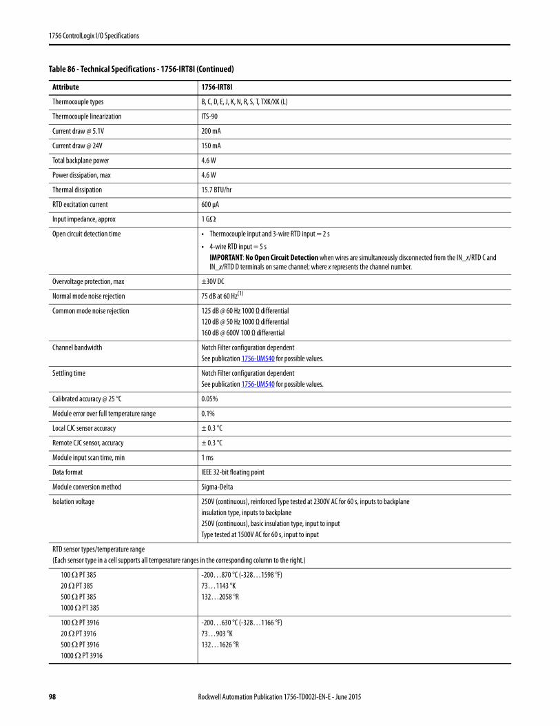
1756 ControlLogix I/O Specifications
Thermocouple types B, C, D, E, J, K, N, R, S, T, TXK/XK (L)
Thermocouple linearization ITS-90
Current draw @ 5.1V 200 mA
Current draw @ 24V 150 mA
Total backplane power 4.6 W
Power dissipation, max 4.6 W
Thermal dissipation 15.7 BTU/hr
RTD excitation current 600 μA
Input impedance, approx 1 GΩ
Open circuit detection time • Thermocouple input and 3-wire RTD input = 2 s
• 4-wire RTD input = 5 sIMPORTANT: No Open Circuit Detection when wires are simultaneously disconnected from the IN_x/RTD C and IN_x/RTD D terminals on same channel; where x represents the channel number.
Overvoltage protection, max ±30V DC
Normal mode noise rejection 75 dB at 60 Hz(1)
Common mode noise rejection 125 dB @ 60 Hz 1000 Ω differential120 dB @ 50 Hz 1000 Ω differential160 dB @ 600V 100 Ω differential
Channel bandwidth Notch Filter configuration dependentSee publication 1756-UM540 for possible values.
Settling time Notch Filter configuration dependentSee publication 1756-UM540 for possible values.
Calibrated accuracy @ 25 °C 0.05%
Module error over full temperature range 0.1%
Local CJC sensor accuracy ± 0.3 °C
Remote CJC sensor, accuracy ± 0.3 °C
Module input scan time, min 1 ms
Data format IEEE 32-bit floating point
Module conversion method Sigma-Delta
Isolation voltage 250V (continuous), reinforced Type tested at 2300V AC for 60 s, inputs to backplaneinsulation type, inputs to backplane250V (continuous), basic insulation type, input to inputType tested at 1500V AC for 60 s, input to input
RTD sensor types/temperature range(Each sensor type in a cell supports all temperature ranges in the corresponding column to the right.)
100 Ω PT 38520 Ω PT 385500 Ω PT 3851000 Ω PT 385
-200…870 °C (-328…1598 °F)73…1143 °K132…2058 °R
100 Ω PT 391620 Ω PT 3916500 Ω PT 39161000 Ω PT 3916
-200…630 °C (-328…1166 °F)73…903 °K132…1626 °R
Table 86 - Technical Specifications - 1756-IRT8I (Continued)
Attribute 1756-IRT8I
98 Rockwell Automation Publication 1756-TD002I-EN-E - June 2015
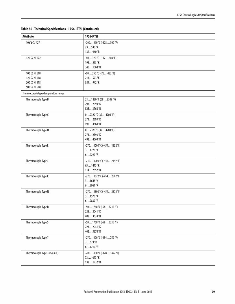
1756 ControlLogix I/O Specifications
10 Ω CU 427 -200…260 °C (-328…500 °F)73…533 °K132…960 °R
120 Ω NI 672 -80…320 °C (-112…608 °F)193…593 °K348…1068 °R
100 Ω NI 618120 Ω NI 618200 Ω NI 618500 Ω NI 618
-60…250 °C (-76…482 °F)213…523 °K384…942 °R
Thermocouple type/temperature range
Thermocouple Type B 21…1820 °C (68…3308 °F)293…2093 °K528…3768 °R
Thermocouple Type C 0…2320 °C (32…4208 °F)273…2593 °K492…4668 °R
Thermocouple Type D 0…2320 °C (32…4208 °F)273…2593 °K492…4668 °R
Thermocouple Type E -270…1000 °C (-454…1832 °F)3…1273 °K6…2292 °R
Thermocouple Type J -210…1200 °C (-346…2192 °F)63…1473 °K114…2652 °R
Thermocouple Type K -270…1372 °C (-454…2502 °F)3…1645 °K6…2961 °R
Thermocouple Type N -270…1300 °C (-454…2372 °F)3…1573 °K6…2832 °R
Thermocouple Type R -50…1768 °C (-58…3215 °F)223…2041 °K402…3674 °R
Thermocouple Type S -50…1768 °C (-58…3215 °F)223…2041 °K402…3674 °R
Thermocouple Type T -270…400 °C (-454…752 °F)3…673 °K6…1212 °R
Thermocouple Type TXK/XK (L) -200…800 °C (-328…1472 °F)73…1073 °K132…1932 °R
Table 86 - Technical Specifications - 1756-IRT8I (Continued)
Attribute 1756-IRT8I
Rockwell Automation Publication 1756-TD002I-EN-E - June 2015 99
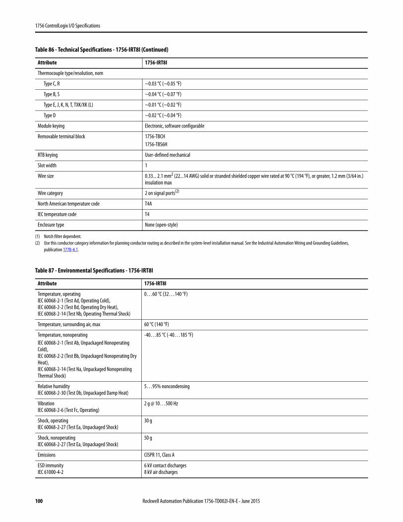
1756 ControlLogix I/O Specifications
Thermocouple type/resolution, nom
Type C, R ~0.03 °C (~0.05 °F)
Type B, S ~0.04 °C (~0.07 °F)
Type E, J, K, N, T, TXK/XK (L) ~0.01 °C (~0.02 °F)
Type D ~0.02 °C (~0.04 °F)
Module keying Electronic, software configurable
Removable terminal block 1756-TBCH1756-TBS6H
RTB keying User-defined mechanical
Slot width 1
Wire size 0.33... 2.1 mm2 (22...14 AWG) solid or stranded shielded copper wire rated at 90 °C (194 °F), or greater, 1.2 mm (3/64 in.) insulation max
Wire category 2 on signal ports(2)
North American temperature code T4A
IEC temperature code T4
Enclosure type None (open-style)
(1) Notch filter dependent.(2) Use this conductor category information for planning conductor routing as described in the system-level installation manual. See the Industrial Automation Wiring and Grounding Guidelines,
publication 1770-4.1.
Table 87 - Environmental Specifications - 1756-IRT8I
Attribute 1756-IRT8I
Temperature, operatingIEC 60068-2-1 (Test Ad, Operating Cold),IEC 60068-2-2 (Test Bd, Operating Dry Heat),IEC 60068-2-14 (Test Nb, Operating Thermal Shock)
0…60 °C (32…140 °F)
Temperature, surrounding air, max 60 °C (140 °F)
Temperature, nonoperatingIEC 60068-2-1 (Test Ab, Unpackaged Nonoperating Cold),IEC 60068-2-2 (Test Bb, Unpackaged Nonoperating Dry Heat),IEC 60068-2-14 (Test Na, Unpackaged Nonoperating Thermal Shock)
-40…85 °C (-40…185 °F)
Relative humidityIEC 60068-2-30 (Test Db, Unpackaged Damp Heat)
5…95% noncondensing
VibrationIEC 60068-2-6 (Test Fc, Operating)
2 g @ 10…500 Hz
Shock, operatingIEC 60068-2-27 (Test Ea, Unpackaged Shock)
30 g
Shock, nonoperatingIEC 60068-2-27 (Test Ea, Unpackaged Shock)
50 g
Emissions CISPR 11, Class A
ESD immunityIEC 61000-4-2
6 kV contact discharges8 kV air discharges
Table 86 - Technical Specifications - 1756-IRT8I (Continued)
Attribute 1756-IRT8I
100 Rockwell Automation Publication 1756-TD002I-EN-E - June 2015

1756 ControlLogix I/O Specifications
Radiated RF immunityIEC 61000-4-3
10V/m with 1 kHz sine-wave 80% AM from 80… 2000 MHz10V/m with 200 Hz 50% Pulse 100% AM @ 900 MHz10V/m with 200 Hz 50% Pulse 100% AM @ 1890 MHz3V/m with 1 kHz sine-wave 80% AM from 2000…2700 MHz
EFT/B immunityIEC 61000-4-4
±4 kV at 5 kHz on shielded signal ports
Surge transient immunityIEC 61000-4-5
±2 kV line-earth (CM) on shielded signal ports
Conducted RF immunityIEC 61000-4-6
10V rms with 1 kHz sine-wave 80% AM from 150 kHz…80 MHz
Table 88 - Certifications - 1756-IRT8I
Certification(1)
(1) When marked. See the Product Certification link at http://www.ab.com for Declarations of Conformity, Certificates, and other certification details.
1756-IRT8I
c-UL-us UL Listed Industrial Control Equipment, certified for US and Canada. See UL File E65584.UL Listed for Class I, Division 2 Group A,B,C,D Hazardous Locations, certified for U.S. and Canada. See UL File E194810.
CE European Union 2004/108/IEC EMC Directive, compliant with:• EN 61326-1; Meas./Control/Lab., Industrial Requirements• EN 61000-6-2; Industrial Immunity• EN 61000-6-4; Industrial Emissions• EN 61131-2; Programmable Controllers (Clause 8, Zone A & B)European Union 2006/95/EC LVD, compliant with:EN 61131-2; Programmable Controllers (Clause 11)
C-Tick Australian Radiocommunications Act, compliant with:EN 61000-6-4; Industrial Emissions
Ex European Union 94/9/EC ATEX Directive, compliant with:• EN 60079-15; Potentially Explosive Atmospheres, Protection "n"• EN 60079-0; General Requirements II 3 G Ex nA IIC T4 Gc X
KC Korean Registration of Broadcasting and Communications Equipment, compliant with:Article 58-2 of Radio Waves Act, Clause 3
Table 87 - Environmental Specifications - 1756-IRT8I (Continued)
Attribute 1756-IRT8I
Rockwell Automation Publication 1756-TD002I-EN-E - June 2015 101
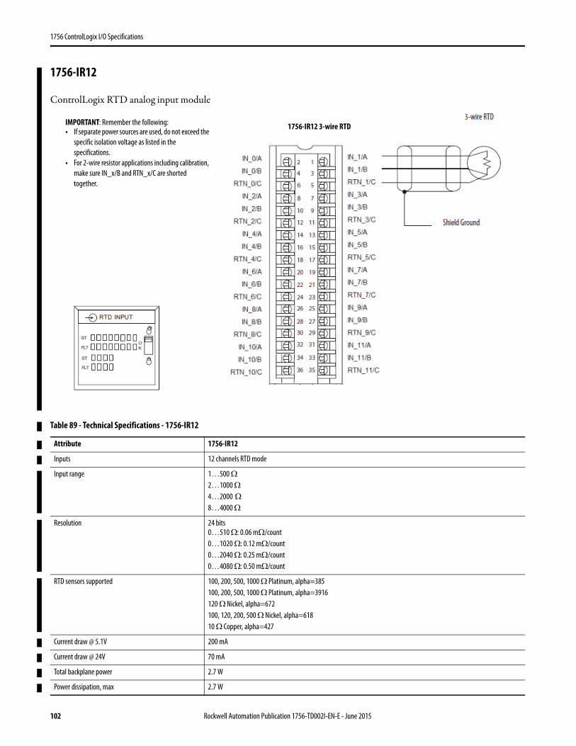
1756 ControlLogix I/O Specifications
1756-IR12
ControlLogix RTD analog input module
Table 89 - Technical Specifications - 1756-IR12
Attribute 1756-IR12
Inputs 12 channels RTD mode
Input range 1…500 Ω2…1000 Ω4…2000 Ω
8…4000 Ω
Resolution 24 bits0…510 Ω: 0.06 mΩ/count0…1020 Ω: 0.12 mΩ/count0…2040 Ω: 0.25 mΩ/count0…4080 Ω: 0.50 mΩ/count
RTD sensors supported 100, 200, 500, 1000 Ω Platinum, alpha=385100, 200, 500, 1000 Ω Platinum, alpha=3916120 Ω Nickel, alpha=672100, 120, 200, 500 Ω Nickel, alpha=61810 Ω Copper, alpha=427
Current draw @ 5.1V 200 mA
Current draw @ 24V 70 mA
Total backplane power 2.7 W
Power dissipation, max 2.7 W
IMPORTANT: Remember the following:• If separate power sources are used, do not exceed the
specific isolation voltage as listed in the specifications.
• For 2-wire resistor applications including calibration, make sure IN_x/B and RTN_x/C are shorted together.
1756-IR12 3-wire RTD
102 Rockwell Automation Publication 1756-TD002I-EN-E - June 2015
1756 ControlLogix I/O Specifications
Thermal dissipation 9.2 BTU/hr
RTD excitation current 600 μA
Overvoltage protection, max ±30V DC
Common mode noise rejection 120 dB @ 60 Hz 1000 Ω differential100 dB @ 50 Hz 1000 Ω differential
Channel bandwidth Notch Filter configuration dependentSee publication 1756-UM540 for possible values.
Settling time Notch Filter configuration dependentSee publication 1756-UM540 for possible values.
Open circuit detection Positive full-scale reading within 2 s
Calibrated accuracy @ 25 °C 0…510 Ω range: 0.1%Other Ω ranges: 0.25%
Module error over full temperature range 0…510 Ω range: 0.2%Other Ω ranges: 0.5%
Module input scan time, min 50 ms
Data format IEEE 32-bit floating point
Module conversion method Sigma-Delta
Isolation Voltage 250V (continuous), reinforced insulation type, inputs to backplaneNo isolation between individual inputsType tested at 1800V AC for 60s
RTD sensor types/temperature range(Each sensor type in a cell supports all temperature ranges in the corresponding column to the right.)
100 Ω PT 38520 Ω PT 385500 Ω PT 3851000 Ω PT 385
-200…870 °C (-328…1598 °F)73…1143 °K132…2058 °R
100 Ω PT 391620 Ω PT 3916500 Ω PT 39161000 Ω PT 3916
-200…630 °C (-328…1166 °F)73…903 °K132…1626 °R
10 Ω CU 427 -200…260 °C (-328…500 °F)73…533 °K132…960 °R
120 Ω NI 672 -80…320 °C (-112…608 °F)193…593 °K348…1068 °R
100 Ω NI 618120 Ω NI 618200 Ω NI 618500 Ω NI 618
-60…250 °C (-76…482 °F)213…523 °K384…942 °R
Module keying Electronic, software configurable
Removable terminal block 1756-TBCH1756-TBS6H
RTB keying User-defined mechanical
Slot width 1
Table 89 - Technical Specifications - 1756-IR12
Rockwell Automation Publication 1756-TD002I-EN-E - June 2015 103
1756 ControlLogix I/O Specifications
Wire size 0.33... 2.1 mm2 (22...14 AWG) solid or stranded shielded copper wire rated at 90 °C (194 °F), or greater, 1.2 mm (3/64 in.) insulation max
Wire category 2 on signal ports(1)
North American Temp Code T4A
ATEX Temp Code T4
IECEx Temp Code T4
Enclosure type None (open-style)
(1) Use this conductor category information for planning conductor routing as described in the system-level installation manual. See the Industrial Automation Wiring and Grounding Guidelines, publication 1770-4.1.
Table 90 - Environmental Specifications - 1756-IR12
Attribute 1756-IR12
Temperature, operatingIEC 60068-2-1 (Test Ad, Operating Cold),IEC 60068-2-2 (Test Bd, Operating Dry Heat),IEC 60068-2-14 (Test Nb, Operating Thermal Shock)
0…60 °C (32…140 °F)
Temperature, surrounding air, max. 60 °C (140 °F)
Temperature, nonoperatingIEC 60068-2-1 (Test Ab, Unpackaged Nonoperating Cold),IEC 60068-2-2 (Test Bb, Unpackaged Nonoperating Dry Heat),IEC 60068-2-14 (Test Na, Unpackaged Nonoperating Thermal Shock)
-40…85 °C (-40…185 °F)
Relative humidityIEC 60068-2-30 (Test Db, Unpackaged Damp Heat)
5…95% noncondensing
Vibration 2 g @ 10…500 Hz
Shock, operatingIEC 60068-2-27 (Test Ea, Unpackaged Shock)
30 g
Shock, nonoperatingIEC 60068-2-27 (Test Ea, Unpackaged Shock)
50 g
EmissionsIEC 61000-6-4
CISPR 11, Class A
ESD ImmunityIEC 61000-4-2
6 kV contact discharges8 kV air discharges
Radiated RF ImmunityIEC 61000-4-3
10V/m with 1 kHz sine-wave 80% AM from 80…2000 MHz10V/m with 200 Hz 50% Pulse 100% AM at 900 MHz10V/m with 200 Hz 50% Pulse 100% AM at 1890 MHz3V/m with 1 kHz sine-wave 80% AM from 2000…2700 MHz
EFT/B ImmunityIEC 61000-4-4
±2 kV at 5/100kHz on shielded ports
Surge Transient ImmunityIEC 61000-4-5
±2 kV line-earth(CM) on shielded ports
Conducted RF ImmunityIEC 61000-4-6
10V rms with 1 kHz sine-wave 80% AM from 150 kHz…80 MHz
Table 89 - Technical Specifications - 1756-IR12
104 Rockwell Automation Publication 1756-TD002I-EN-E - June 2015
1756 ControlLogix I/O Specifications
Table 91 - Certifications - 1756-IR12
Certification(1)
(when product is marked)
(1) See the Product Certification link at www.ab.com for Declarations of Conformity, Certificates, and other certification details.
Description
c-UL-us UL Listed Industrial Control Equipment, certified for US and Canada. See UL File E65584.UL Listed for Class I, Division 2 Group A,B,C,D Hazardous Locations, certified for U.S. and Canada. See UL File E194810.
CE European Union 2004/108/EC EMC Directive, compliant with:• EN 61326-1; Meas./Control/Lab., Industrial Requirements• EN 61000-6-2; Industrial Immunity• EN 61000-6-4; Industrial Emissions• EN 61131-2; Programmable Controllers (Clause 8, Zone A & B)European Union 2006/95/EC LVD, compliant with:• EN 61010-2-201; Control Equipment Safety Requirements
RCM Australian Radiocommunications Act, compliant with:• EN 61000-6-4; Industrial Emissions
Ex European Union 94/9/EC ATEX Directive, compliant with:• EN 60079-0; General Requirements• EN 60079-15; Potentially Explosive Atmospheres, Protection "n" II 3 G Ex nA IIC T4 Gc DEMKO15ATEX1482X
IECEx IECEx System, compliant with:• IEC 60079-0; General Requirements• IEC 60079-15; Potentially Explosive Atmospheres, Protection "n" II 3 G Ex nA IIC T4 Gc IECEx UL 15.0053X
KC Korean Registration of Broadcasting and Communications Equipment, compliant with:• Article 58-2 of Radio Waves Act, Clause 3
EAC Russian Customs Union TR CU 020/2011 EMC Technical RegulationRussian Customs Union TR CU 004/2011 LV Technical Regulation
Rockwell Automation Publication 1756-TD002I-EN-E - June 2015 105
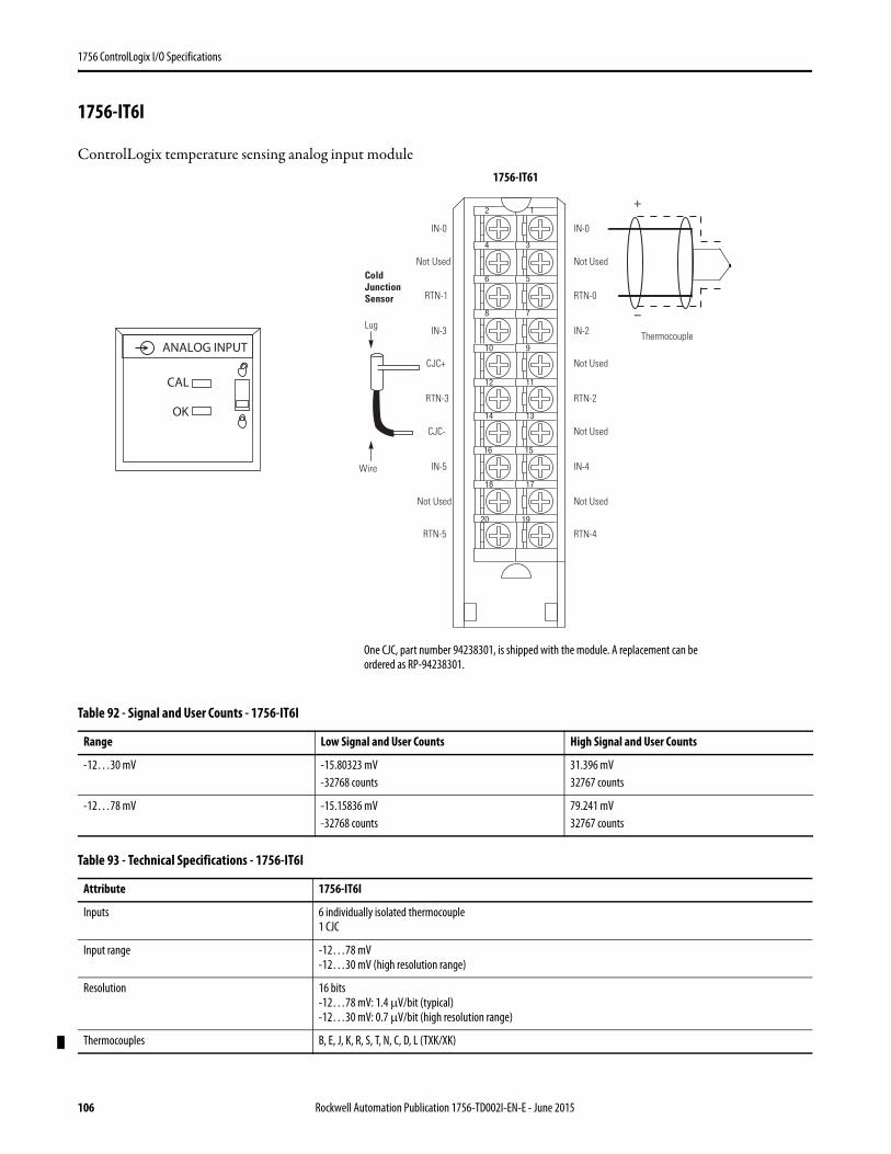
1756 ControlLogix I/O Specifications
1756-IT6I
ControlLogix temperature sensing analog input module
Table 92 - Signal and User Counts - 1756-IT6I
Range Low Signal and User Counts High Signal and User Counts
-12…30 mV -15.80323 mV-32768 counts
31.396 mV32767 counts
-12…78 mV -15.15836 mV-32768 counts
79.241 mV32767 counts
Table 93 - Technical Specifications - 1756-IT6I
Attribute 1756-IT6I
Inputs 6 individually isolated thermocouple1 CJC
Input range -12…78 mV-12…30 mV (high resolution range)
Resolution 16 bits-12…78 mV: 1.4 μV/bit (typical)-12…30 mV: 0.7 μV/bit (high resolution range)
Thermocouples B, E, J, K, R, S, T, N, C, D, L (TXK/XK)
12
34
56
78
910
1112
1314
1516
1718
1920
+
–
Cold Junction Sensor
Thermocouple
Wire
IN-0
Not Used
RTN-0
IN-2
Not Used
RTN-2
Not Used
IN-4
Not Used
RTN-4
IN-0
Not Used
RTN-1
IN-3
CJC+
RTN-3
CJC-
IN-5
Not Used
RTN-5
Lug
One CJC, part number 94238301, is shipped with the module. A replacement can be ordered as RP-94238301.
ANALOG INPUT
CAL
OK
1756-IT61
106 Rockwell Automation Publication 1756-TD002I-EN-E - June 2015
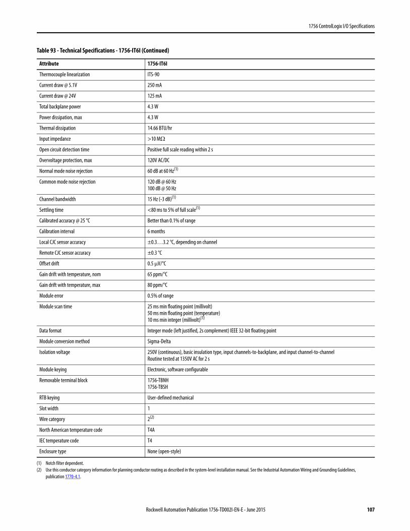
1756 ControlLogix I/O Specifications
Thermocouple linearization ITS-90
Current draw @ 5.1V 250 mA
Current draw @ 24V 125 mA
Total backplane power 4.3 W
Power dissipation, max 4.3 W
Thermal dissipation 14.66 BTU/hr
Input impedance >10 MΩ
Open circuit detection time Positive full scale reading within 2 s
Overvoltage protection, max 120V AC/DC
Normal mode noise rejection 60 dB at 60 Hz(1)
Common mode noise rejection 120 dB @ 60 Hz100 dB @ 50 Hz
Channel bandwidth 15 Hz (-3 dB)(1)
Settling time <80 ms to 5% of full scale(1)
Calibrated accuracy @ 25 °C Better than 0.1% of range
Calibration interval 6 months
Local CJC sensor accuracy ±0.3…3.2 °C, depending on channel
Remote CJC sensor accuracy ±0.3 °C
Offset drift 0.5 μV/°C
Gain drift with temperature, nom 65 ppm/°C
Gain drift with temperature, max 80 ppm/°C
Module error 0.5% of range
Module scan time 25 ms min floating point (millivolt)50 ms min floating point (temperature)10 ms min integer (millivolt)(1)
Data format Integer mode (left justified, 2s complement) IEEE 32-bit floating point
Module conversion method Sigma-Delta
Isolation voltage 250V (continuous), basic insulation type, input channels-to-backplane, and input channel-to-channelRoutine tested at 1350V AC for 2 s
Module keying Electronic, software configurable
Removable terminal block 1756-TBNH1756-TBSH
RTB keying User-defined mechanical
Slot width 1
Wire category 2(2)
North American temperature code T4A
IEC temperature code T4
Enclosure type None (open-style)
(1) Notch filter dependent.(2) Use this conductor category information for planning conductor routing as described in the system-level installation manual. See the Industrial Automation Wiring and Grounding Guidelines,
publication 1770-4.1.
Table 93 - Technical Specifications - 1756-IT6I (Continued)
Attribute 1756-IT6I
Rockwell Automation Publication 1756-TD002I-EN-E - June 2015 107
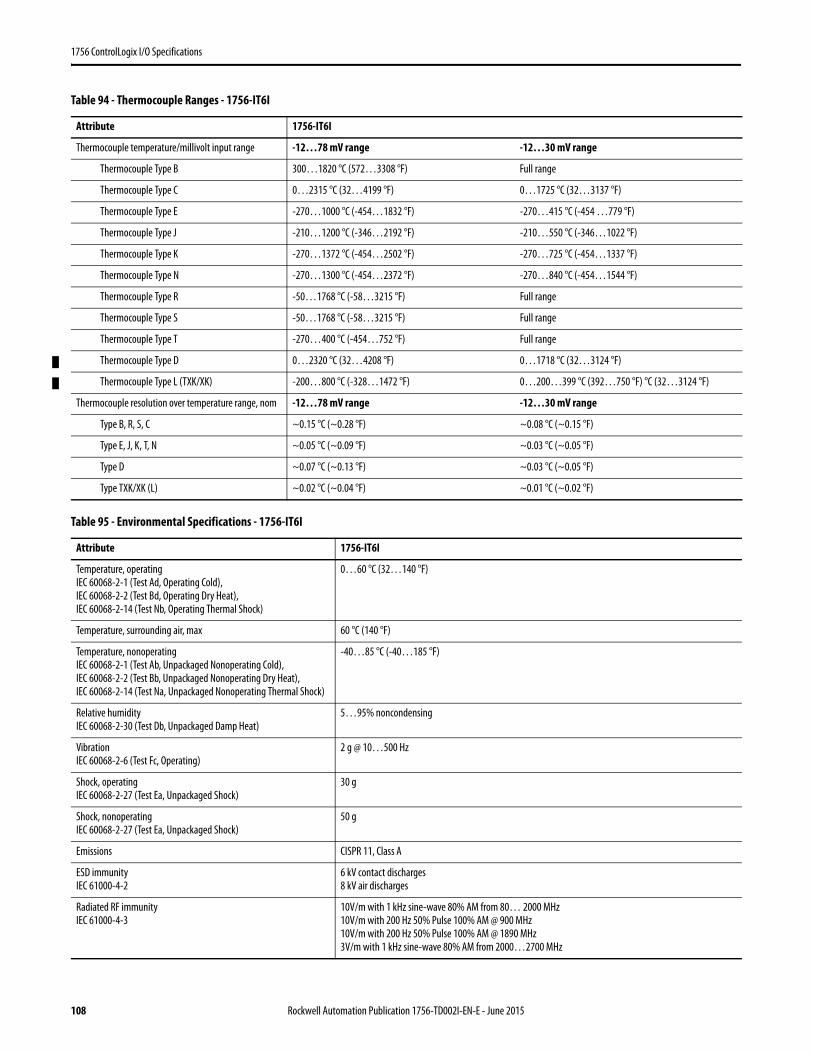
1756 ControlLogix I/O Specifications
Table 94 - Thermocouple Ranges - 1756-IT6I
Attribute 1756-IT6I
Thermocouple temperature/millivolt input range -12…78 mV range -12…30 mV range
Thermocouple Type B 300…1820 °C (572…3308 °F) Full range
Thermocouple Type C 0…2315 °C (32…4199 °F) 0…1725 °C (32…3137 °F)
Thermocouple Type E -270…1000 °C (-454…1832 °F) -270…415 °C (-454 …779 °F)
Thermocouple Type J -210…1200 °C (-346…2192 °F) -210…550 °C (-346…1022 °F)
Thermocouple Type K -270…1372 °C (-454…2502 °F) -270…725 °C (-454…1337 °F)
Thermocouple Type N -270…1300 °C (-454…2372 °F) -270…840 °C (-454…1544 °F)
Thermocouple Type R -50…1768 °C (-58…3215 °F) Full range
Thermocouple Type S -50…1768 °C (-58…3215 °F) Full range
Thermocouple Type T -270…400 °C (-454…752 °F) Full range
Thermocouple Type D 0…2320 °C (32…4208 °F) 0…1718 °C (32…3124 °F)
Thermocouple Type L (TXK/XK) -200…800 °C (-328…1472 °F) 0…200…399 °C (392…750 °F) °C (32…3124 °F)
Thermocouple resolution over temperature range, nom -12…78 mV range -12…30 mV range
Type B, R, S, C ~0.15 °C (~0.28 °F) ~0.08 °C (~0.15 °F)
Type E, J, K, T, N ~0.05 °C (~0.09 °F) ~0.03 °C (~0.05 °F)
Type D ~0.07 °C (~0.13 °F) ~0.03 °C (~0.05 °F)
Type TXK/XK (L) ~0.02 °C (~0.04 °F) ~0.01 °C (~0.02 °F)
Table 95 - Environmental Specifications - 1756-IT6I
Attribute 1756-IT6I
Temperature, operatingIEC 60068-2-1 (Test Ad, Operating Cold),IEC 60068-2-2 (Test Bd, Operating Dry Heat),IEC 60068-2-14 (Test Nb, Operating Thermal Shock)
0…60 °C (32…140 °F)
Temperature, surrounding air, max 60 °C (140 °F)
Temperature, nonoperatingIEC 60068-2-1 (Test Ab, Unpackaged Nonoperating Cold),IEC 60068-2-2 (Test Bb, Unpackaged Nonoperating Dry Heat),IEC 60068-2-14 (Test Na, Unpackaged Nonoperating Thermal Shock)
-40…85 °C (-40…185 °F)
Relative humidityIEC 60068-2-30 (Test Db, Unpackaged Damp Heat)
5…95% noncondensing
VibrationIEC 60068-2-6 (Test Fc, Operating)
2 g @ 10…500 Hz
Shock, operatingIEC 60068-2-27 (Test Ea, Unpackaged Shock)
30 g
Shock, nonoperatingIEC 60068-2-27 (Test Ea, Unpackaged Shock)
50 g
Emissions CISPR 11, Class A
ESD immunityIEC 61000-4-2
6 kV contact discharges8 kV air discharges
Radiated RF immunityIEC 61000-4-3
10V/m with 1 kHz sine-wave 80% AM from 80… 2000 MHz10V/m with 200 Hz 50% Pulse 100% AM @ 900 MHz10V/m with 200 Hz 50% Pulse 100% AM @ 1890 MHz3V/m with 1 kHz sine-wave 80% AM from 2000…2700 MHz
108 Rockwell Automation Publication 1756-TD002I-EN-E - June 2015

1756 ControlLogix I/O Specifications
EFT/B immunityIEC 61000-4-4
±2 kV at 5 kHz on shielded signal ports
Surge transient immunityIEC 61000-4-5
±2 kV line-earth (CM) on shielded signal ports
Conducted RF immunityIEC 61000-4-6
10V rms with 1 kHz sine-wave 80% AM from 150 kHz…80 MHz on shielded signal ports
Table 96 - Certifications - 1756-IT6I
Certification(1) 1756-IT6I
UL UL Listed Industrial Control Equipment. See UL File E65584.
CSA CSA Certified Process Control Equipment. See CSA File LR54689C.CSA Certified Process Control Equipment for Class I, Division 2 Group A,B,C,D Hazardous Locations. See CSA File LR69960C.
CE European Union 2004/108/IEC EMC Directive, compliant with:• EN 61326-1; Meas./Control/Lab., Industrial Requirements• EN 61000-6-2; Industrial Immunity• EN 61000-6-4; Industrial Emissions• EN 61131-2; Programmable Controllers (Clause 8, Zone A & B)European Union 2006/95/EC LVD, compliant with:EN 61131-2; Programmable Controllers (Clause 11)
C-Tick Australian Radiocommunications Act, compliant with:AS/NZS CISPR 11; Industrial Emissions
Ex European Union 94/9/EC ATEX Directive, compliant with:• EN 60079-15; Potentially Explosive Atmospheres, Protection "n"• EN 60079-0; General Requirements II 3 G Ex nA IIC T4 X Gc
FM FM Approved Equipment for use in Class I Division 2 Group A,B,C,D Hazardous Locations
KC Korean Registration of Broadcasting and Communications Equipment, compliant with:Article 58-2 of Radio Waves Act, Clause 3
(1) When marked. See the Product Certification link at http://www.ab.com for Declarations of Conformity, Certificates, and other certification details.
Table 95 - Environmental Specifications - 1756-IT6I (Continued)
Attribute 1756-IT6I
Rockwell Automation Publication 1756-TD002I-EN-E - June 2015 109

1756 ControlLogix I/O Specifications
1756-IT6I2
ControlLogix enhanced thermocouple analog input module
Table 97 - Signal and User Counts - 1756-IT6I2
Range Low Signal and User Counts High Signal and User Counts
-12…30 mV -15.80323 mV-32768 counts
31.396 mV32767 counts
-12…78 mV -15.15836 mV-32768 counts
79.241 mV32767 counts
Table 98 - Technical Specifications - 1756-IT6I2
Attribute 1756-IT6I2
Inputs 6 individually isolated thermocouple2 CJC
Input range -12…78 mV (1.4 μV per bit)-12…30 mV (0.7 μV per bit – high resolution range)
Resolution 16 bits-12…78 mV: 1.4 μV/bit-12…30 mV: 0.7 μV/bit
Thermocouples B, E, J, K, R, S, T, N, C, D, L (TXK/XK)
Thermocouple linearization ITS-90
Current draw @ 5.1V 200 mA
�
Cold Junction Sensor
Thermocouple
Wire
Not Used
CJC–
RTN-0
RTN-1
RTN-
RTN-3
RTN-
RTN-5
CJC–
Not used
Spade Lug
Not Used
CJC+
IN-0
IN-1
IN-2
IN-3
IN-4
IN-5
CJC+
Not used
Wire Spade Lug
Two CJCs, part number 94286501, are shipped with the module. Replacements can be ordered as RP-94286501.
Analog Input
CAL
OK
1756-IT6I Cold Junction Sensor
110 Rockwell Automation Publication 1756-TD002I-EN-E - June 2015

1756 ControlLogix I/O Specifications
Current draw @ 24V 150 mA
Total backplane power 4.6 W
Power dissipation, max 4.6 W
Thermal dissipation 15.7 BTU/hr
Input impedance >10 MΩ
Open circuit detection time Positive full scale reading within 2 s
Overvoltage protection, max 120V AC/DC
Normal mode noise rejection 60 dB at 60 Hz(1)
Common mode noise rejection 160 dB min, tested @ 600V AC/60 Hz applied with 100 Ω differential resistance
Channel bandwidth 15 Hz(1)
Settling time <80 ms to 5% of full scale(1)
Calibrated accuracy @ 25 °C 0.05% of full range @ 25 °C (77 °F) typicalBetter than 0.1% of range @ 25 °C (77 °F) worst case
Calibration interval 12 months
Local CJC sensor accuracy ±0.3 °C
Remote CJC sensor accuracy ±0.3 °C
Offset drift 0.5 μV/°C
Gain drift with temperature, nom 15 ppm/°C1.4 μV/°C for -12…78 mV0.6 μV/°C for -12…30 mV
Gain drift with temperature, max 25 ppm/°C2.3 μV/°C for -12…78 mV1.1 μV/°C for -12…30 mV
Module error 0.15% of range
Module scan time 25 ms min floating point (millivolt)50 ms min floating point (temperature)10 ms min integer (millivolt)(1)
Data format Integer mode (left justified, 2s complement) IEEE 32-bit floating point
Module conversion method Sigma-Delta
Isolation voltage 250V (continuous), basic insulation type, input channels-to-backplane, and input channel-to-channelRoutine tested at 1350V AC for 2 s
Module keying Electronic, software configurable
Removable terminal block 1756-TBNH only
RTB keying User-defined mechanical
Slot width 1
Wire category 2(2)
North American temperature code T4A
IEC temperature code T4
Enclosure type None (open-style)
(1) Notch filter dependent.(2) Use this conductor category information for planning conductor routing as described in the system-level installation manual. See the Industrial Automation Wiring and Grounding Guidelines,
publication 1770-4.1.
Table 98 - Technical Specifications - 1756-IT6I2 (Continued)
Attribute 1756-IT6I2
Rockwell Automation Publication 1756-TD002I-EN-E - June 2015 111
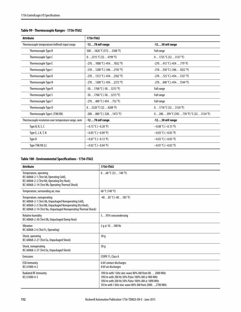
1756 ControlLogix I/O Specifications
Table 99 - Thermocouple Ranges - 1756-IT6I2
Attribute 1756-IT6I2
Thermocouple temperature/millivolt input range -12…78 mV range -12…30 mV range
Thermocouple Type B 300…1820 °C (572…3308 °F) Full range
Thermocouple Type C 0…2315 °C (32…4199 °F) 0…1725 °C (32…3137 °F)
Thermocouple Type E -270…1000 °C (-454…1832 °F) -270…415 °C (-454 …779 °F)
Thermocouple Type J -210…1200 °C (-346…2192 °F) -210…550 °C (-346…1022 °F)
Thermocouple Type K -270…1372 °C (-454…2502 °F) -270…725 °C (-454…1337 °F)
Thermocouple Type N -270…1300 °C (-454…2372 °F) -270…840 °C (-454…1544 °F)
Thermocouple Type R -50…1768 °C (-58…3215 °F) Full range
Thermocouple Type S -50…1768 °C (-58…3215 °F) Full range
Thermocouple Type T -270…400 °C (-454…752 °F) Full range
Thermocouple Type D 0…2320 °C (32…4208 °F) 0…1718 °C (32…3124 °F)
Thermocouple Type L (TXK/XK) -200…800 °C (-328…1472 °F) 0…200…399 °C (392…750 °F) °C (32…3124 °F)
Thermocouple resolution over temperature range, nom -12…78 mV range -12…30 mV range
Type B, R, S, C ~0.15 °C (~0.28 °F) ~0.08 °C (~0.15 °F)
Type E, J, K, T, N ~0.05 °C (~0.09 °F) ~0.03 °C (~0.05 °F)
Type D ~0.07 °C (~0.13 °F) ~0.03 °C (~0.05 °F)
Type TXK/XK (L) ~0.02 °C (~0.04 °F) ~0.01 °C (~0.02 °F)
Table 100 - Environmental Specifications - 1756-IT6I2
Attribute 1756-IT6I2
Temperature, operatingIEC 60068-2-1 (Test Ad, Operating Cold),IEC 60068-2-2 (Test Bd, Operating Dry Heat),IEC 60068-2-14 (Test Nb, Operating Thermal Shock)
0…60 °C (32…140 °F)
Temperature, surrounding air, max 60 °C (140 °F)
Temperature, nonoperatingIEC 60068-2-1 (Test Ab, Unpackaged Nonoperating Cold),IEC 60068-2-2 (Test Bb, Unpackaged Nonoperating Dry Heat),IEC 60068-2-14 (Test Na, Unpackaged Nonoperating Thermal Shock)
-40…85 °C (-40…185 °F)
Relative humidityIEC 60068-2-30 (Test Db, Unpackaged Damp Heat)
5…95% noncondensing
VibrationIEC 60068-2-6 (Test Fc, Operating)
2 g @ 10…500 Hz
Shock, operatingIEC 60068-2-27 (Test Ea, Unpackaged Shock)
30 g
Shock, nonoperatingIEC 60068-2-27 (Test Ea, Unpackaged Shock)
50 g
Emissions CISPR 11, Class A
ESD immunityIEC 61000-4-2
6 kV contact discharges8 kV air discharges
Radiated RF immunityIEC 61000-4-3
10V/m with 1 kHz sine-wave 80% AM from 80… 2000 MHz10V/m with 200 Hz 50% Pulse 100% AM @ 900 MHz10V/m with 200 Hz 50% Pulse 100% AM @ 1890 MHz3V/m with 1 kHz sine-wave 80% AM from 2000…2700 MHz
112 Rockwell Automation Publication 1756-TD002I-EN-E - June 2015
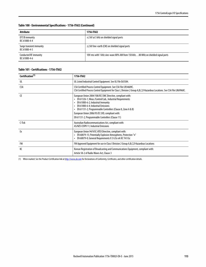
1756 ControlLogix I/O Specifications
EFT/B immunityIEC 61000-4-4
±2 kV at 5 kHz on shielded signal ports
Surge transient immunityIEC 61000-4-5
±2 kV line-earth (CM) on shielded signal ports
Conducted RF immunityIEC 61000-4-6
10V rms with 1 kHz sine-wave 80% AM from 150 kHz…80 MHz on shielded signal ports
Table 101 - Certifications - 1756-IT6I2
Certification(1)
(1) When marked. See the Product Certification link at http://www.ab.com for Declarations of Conformity, Certificates, and other certification details.
1756-IT6I2
UL UL Listed Industrial Control Equipment. See UL File E65584.
CSA CSA Certified Process Control Equipment. See CSA File LR54689C.CSA Certified Process Control Equipment for Class I, Division 2 Group A,B,C,D Hazardous Locations. See CSA File LR69960C.
CE European Union 2004/108/IEC EMC Directive, compliant with:• EN 61326-1; Meas./Control/Lab., Industrial Requirements• EN 61000-6-2; Industrial Immunity• EN 61000-6-4; Industrial Emissions• EN 61131-2; Programmable Controllers (Clause 8, Zone A & B)European Union 2006/95/EC LVD, compliant with:EN 61131-2; Programmable Controllers (Clause 11)
C-Tick Australian Radiocommunications Act, compliant with:AS/NZS CISPR 11; Industrial Emissions
Ex European Union 94/9/EC ATEX Directive, compliant with:• EN 60079-15; Potentially Explosive Atmospheres, Protection "n"• EN 60079-0; General Requirements II 3 G Ex nA IIC T4 X Gc
FM FM Approved Equipment for use in Class I Division 2 Group A,B,C,D Hazardous Locations
KC Korean Registration of Broadcasting and Communications Equipment, compliant with:Article 58-2 of Radio Waves Act, Clause 3
Table 100 - Environmental Specifications - 1756-IT6I2 (Continued)
Attribute 1756-IT6I2
Rockwell Automation Publication 1756-TD002I-EN-E - June 2015 113
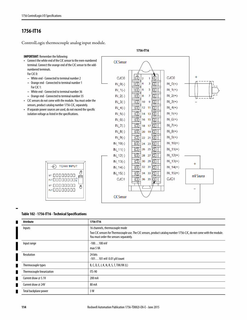
1756 ControlLogix I/O Specifications
1756-IT16
ControlLogix thermocouple analog input module.
Table 102 - 1756-IT16 - Technical Specifications
Attribute 1756-IT16
Inputs 16 channels, thermocouple modeTwo CJC sensors for Thermocouple use. The CJC sensors, product catalog number 1756-CJC, do not come with the module. You must order the sensors separately.
Input range -100…100 mVmax 5 VA
Resolution 24 bits-101…101 mV: 0.01 μV/count
Thermocouple types B, C, D, E, J, K, N, R, S, T, TXK/XK (L)
Thermocouple linearization ITS-90
Current draw @ 5.1V 200 mA
Current draw @ 24V 80 mA
Total backplane power 3 W
IMPORTANT: Remember the following:• Connect the white end of the CJC sensor to the even-numbered
terminal. Connect the orange end of the CJC sensor to the odd-numbered terminals. For CJC 0:– White end - Connected to terminal number 2– Orange end - Connected to terminal number 1
For CJC 1:– White end - Connected to terminal number 36– Orange end - Connected to terminal number 35
• CJC sensors do not come with the module. You must order the sensors, product catalog number 1756-CJC, separately.
• If separate power sources are used, do not exceed the specific isolation voltage as listed in the specifications.
1756-IT16
114 Rockwell Automation Publication 1756-TD002I-EN-E - June 2015
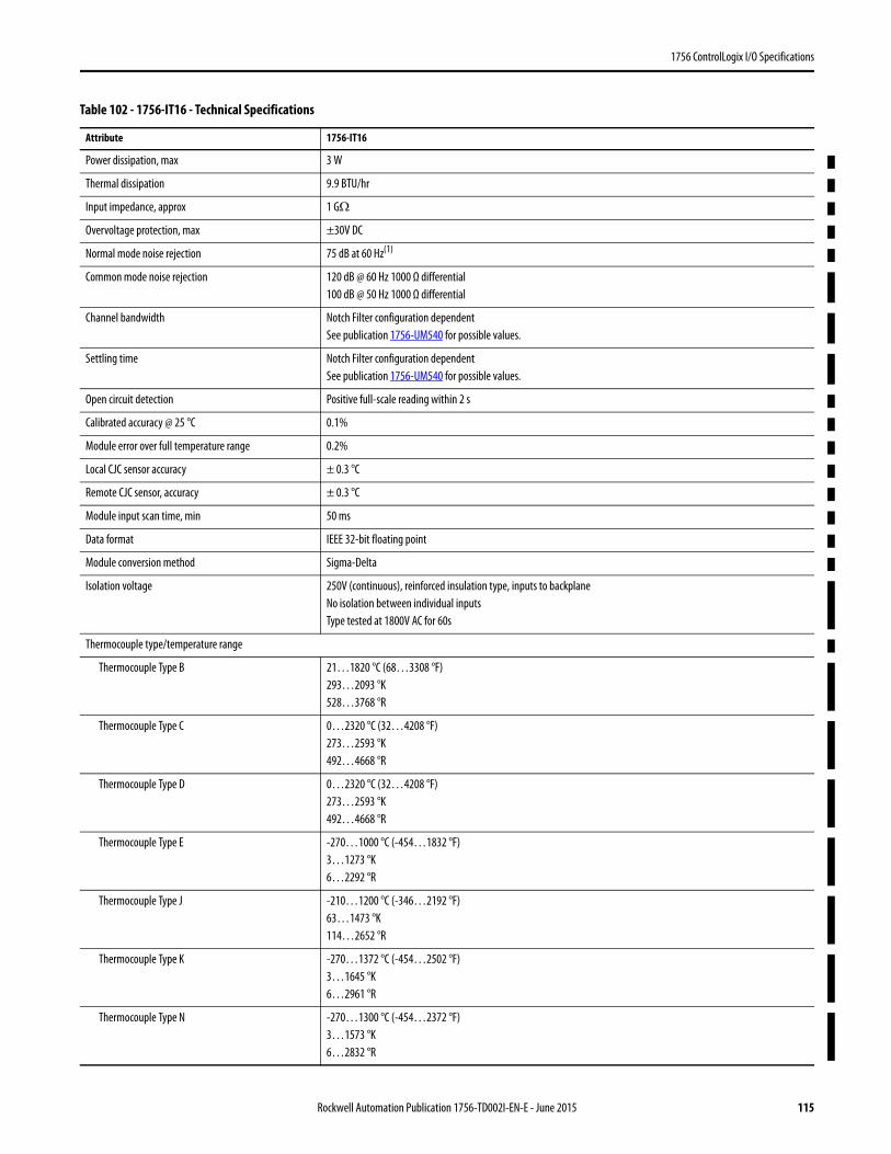
1756 ControlLogix I/O Specifications
Power dissipation, max 3 W
Thermal dissipation 9.9 BTU/hr
Input impedance, approx 1 GΩ
Overvoltage protection, max ±30V DC
Normal mode noise rejection 75 dB at 60 Hz(1)
Common mode noise rejection 120 dB @ 60 Hz 1000 Ω differential100 dB @ 50 Hz 1000 Ω differential
Channel bandwidth Notch Filter configuration dependentSee publication 1756-UM540 for possible values.
Settling time Notch Filter configuration dependentSee publication 1756-UM540 for possible values.
Open circuit detection Positive full-scale reading within 2 s
Calibrated accuracy @ 25 °C 0.1%
Module error over full temperature range 0.2%
Local CJC sensor accuracy ± 0.3 °C
Remote CJC sensor, accuracy ± 0.3 °C
Module input scan time, min 50 ms
Data format IEEE 32-bit floating point
Module conversion method Sigma-Delta
Isolation voltage 250V (continuous), reinforced insulation type, inputs to backplaneNo isolation between individual inputsType tested at 1800V AC for 60s
Thermocouple type/temperature range
Thermocouple Type B 21…1820 °C (68…3308 °F)293…2093 °K528…3768 °R
Thermocouple Type C 0…2320 °C (32…4208 °F)273…2593 °K492…4668 °R
Thermocouple Type D 0…2320 °C (32…4208 °F)273…2593 °K492…4668 °R
Thermocouple Type E -270…1000 °C (-454…1832 °F)3…1273 °K6…2292 °R
Thermocouple Type J -210…1200 °C (-346…2192 °F)63…1473 °K114…2652 °R
Thermocouple Type K -270…1372 °C (-454…2502 °F)3…1645 °K6…2961 °R
Thermocouple Type N -270…1300 °C (-454…2372 °F)3…1573 °K6…2832 °R
Table 102 - 1756-IT16 - Technical Specifications
Attribute 1756-IT16
Rockwell Automation Publication 1756-TD002I-EN-E - June 2015 115
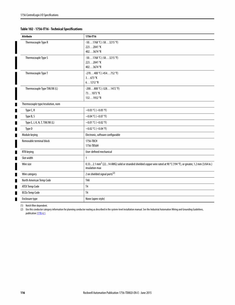
1756 ControlLogix I/O Specifications
Thermocouple Type R -50…1768 °C (-58…3215 °F)223…2041 °K402…3674 °R
Thermocouple Type S -50…1768 °C (-58…3215 °F)223…2041 °K402…3674 °R
Thermocouple Type T -270…400 °C (-454…752 °F)3…673 °K6…1212 °R
Thermocouple Type TXK/XK (L) -200…800 °C (-328…1472 °F)73…1073 °K132…1932 °R
Thermocouple type/resolution, nom
Type C, R ~0.03 °C (~0.05 °F)
Type B, S ~0.04 °C (~0.07 °F)
Type E, J, K, N, T, TXK/XK (L) ~0.01 °C (~0.02 °F)
Type D ~0.02 °C (~0.04 °F)
Module keying Electronic, software configurable
Removable terminal block 1756-TBCH1756-TBS6H
RTB keying User-defined mechanical
Slot width 1
Wire size 0.33... 2.1 mm2 (22...14 AWG) solid or stranded shielded copper wire rated at 90 °C (194 °F), or greater, 1.2 mm (3/64 in.) insulation max
Wire category 2 on shielded signal ports(2)
North American Temp Code T4A
ATEX Temp Code T4
IECEx Temp Code T4
Enclosure type None (open-style)
(1) Notch filter dependent.(2) Use this conductor category information for planning conductor routing as described in the system-level installation manual. See the Industrial Automation Wiring and Grounding Guidelines,
publication 1770-4.1.
Table 102 - 1756-IT16 - Technical Specifications
Attribute 1756-IT16
116 Rockwell Automation Publication 1756-TD002I-EN-E - June 2015

1756 ControlLogix I/O Specifications
Table 103 - 1756-IT16 - Environmental Specifications
Attribute 1756-IT16
Temperature, operatingIEC 60068-2-1 (Test Ad, Operating Cold),IEC 60068-2-2 (Test Bd, Operating Dry Heat),IEC 60068-2-14 (Test Nb, Operating Thermal Shock)
0…60 °C (32…140 °F)
Temperature, surrounding air, max. 60 °C (140 °F)
Temperature, nonoperatingIEC 60068-2-1 (Test Ab, Unpackaged Nonoperating Cold),IEC 60068-2-2 (Test Bb, Unpackaged Nonoperating Dry Heat),IEC 60068-2-14 (Test Na, Unpackaged Nonoperating Thermal Shock)
-40…85 °C (-40…185 °F)
Relative humidityIEC 60068-2-30 (Test Db, Unpackaged Damp Heat)
5…95% noncondensing
VibrationIEC 60068-2-6 (Test Fc, Operating)
2 g @ 10…500 Hz
Shock, operatingIEC 60068-2-27 (Test Ea, Unpackaged Shock)
30 g
Shock, nonoperatingIEC 60068-2-27 (Test Ea, Unpackaged Shock)
50 g
EmissionsIEC 61000-6-4
CISPR 11, Class A
ESD ImmunityIEC 61000-4-2
6 kV contact discharges8 kV air discharges
Radiated RF ImmunityIEC 61000-4-3
10V/m with 1 kHz sine-wave 80% AM from 80…2000 MHz10V/m with 200 Hz 50% Pulse 100% AM at 900 MHz10V/m with 200 Hz 50% Pulse 100% AM at 1890 MHz3V/m with 1 kHz sine-wave 80% AM from 2000…2700 MHz
EFT/B ImmunityIEC 61000-4-4
±2 kV at 5/100kHz on shielded ports
Surge Transient ImmunityIEC 61000-4-5
±2 kV line-earth (CM) on shielded signal ports
Conducted RF ImmunityIEC 61000-4-6
10V rms with 1 kHz sine-wave 80% AM from 150 kHz…80 MHz
Enclosure Type Rating None (open-style)
Rockwell Automation Publication 1756-TD002I-EN-E - June 2015 117
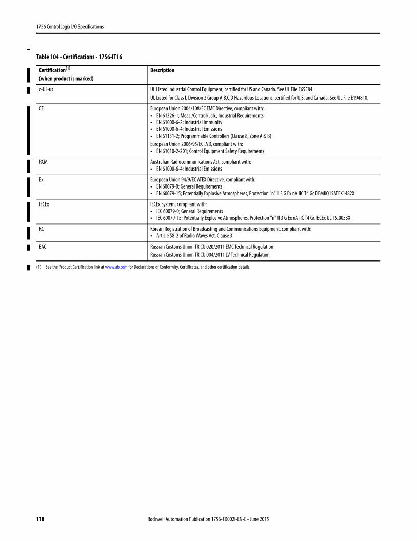
1756 ControlLogix I/O Specifications
Table 104 - Certifications - 1756-IT16
Certification(1)
(when product is marked)
(1) See the Product Certification link at www.ab.com for Declarations of Conformity, Certificates, and other certification details.
Description
c-UL-us UL Listed Industrial Control Equipment, certified for US and Canada. See UL File E65584.UL Listed for Class I, Division 2 Group A,B,C,D Hazardous Locations, certified for U.S. and Canada. See UL File E194810.
CE European Union 2004/108/EC EMC Directive, compliant with:• EN 61326-1; Meas./Control/Lab., Industrial Requirements• EN 61000-6-2; Industrial Immunity• EN 61000-6-4; Industrial Emissions• EN 61131-2; Programmable Controllers (Clause 8, Zone A & B)European Union 2006/95/EC LVD, compliant with:• EN 61010-2-201; Control Equipment Safety Requirements
RCM Australian Radiocommunications Act, compliant with:• EN 61000-6-4; Industrial Emissions
Ex European Union 94/9/EC ATEX Directive, compliant with:• EN 60079-0; General Requirements• EN 60079-15; Potentially Explosive Atmospheres, Protection "n" II 3 G Ex nA IIC T4 Gc DEMKO15ATEX1482X
IECEx IECEx System, compliant with:• IEC 60079-0; General Requirements• IEC 60079-15; Potentially Explosive Atmospheres, Protection "n" II 3 G Ex nA IIC T4 Gc IECEx UL 15.0053X
KC Korean Registration of Broadcasting and Communications Equipment, compliant with:• Article 58-2 of Radio Waves Act, Clause 3
EAC Russian Customs Union TR CU 020/2011 EMC Technical RegulationRussian Customs Union TR CU 004/2011 LV Technical Regulation
118 Rockwell Automation Publication 1756-TD002I-EN-E - June 2015
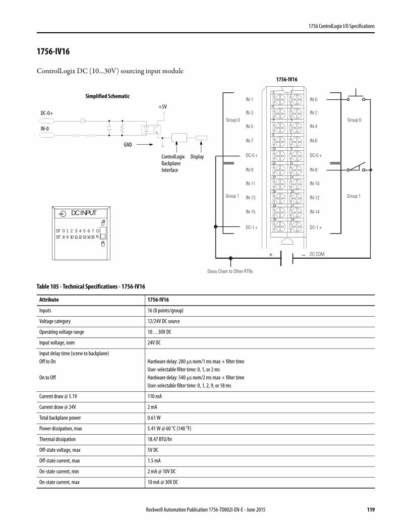
1756 ControlLogix I/O Specifications
1756-IV16
ControlLogix DC (10…30V) sourcing input module
Table 105 - Technical Specifications - 1756-IV16
Attribute 1756-IV16
Inputs 16 (8 points/group)
Voltage category 12/24V DC source
Operating voltage range 10…30V DC
Input voltage, nom 24V DC
Input delay time (screw to backplane)Off to On
On to Off
Hardware delay: 280 μs nom/1 ms max + filter timeUser-selectable filter time: 0, 1, or 2 msHardware delay: 540 μs nom/2 ms max + filter timeUser-selectable filter time: 0, 1, 2, 9, or 18 ms
Current draw @ 5.1V 110 mA
Current draw @ 24V 2 mA
Total backplane power 0.61 W
Power dissipation, max 5.41 W @ 60 °C (140 °F)
Thermal dissipation 18.47 BTU/hr
Off-state voltage, max 5V DC
Off-state current, max 1.5 mA
On-state current, min 2 mA @ 10V DC
On-state current, max 10 mA @ 30V DC
12
34
56
78
910
1112
1314
1516
1718
1920
–+
Daisy Chain to Other RTBs
Group 0Group 0
Group 1Group 1
DC COM
IN-0
IN-2
IN-4
IN-6
DC-0 +
IN-8
IN-10
IN-12
IN-14
DC-1 +
IN-1
IN-3
IN-5
IN-7
DC-0 +
IN-9
IN-11
IN-13
IN-15
DC-1 +
ControlLogix Backplane Interface
Simplified Schematic
Display
GND
IN-0
DC-0++5V
DC INPUT
ST 0 1 2 3 4 5 6 7ST 8 9 10 1112131415
OK
1756-IV16
Rockwell Automation Publication 1756-TD002I-EN-E - June 2015 119
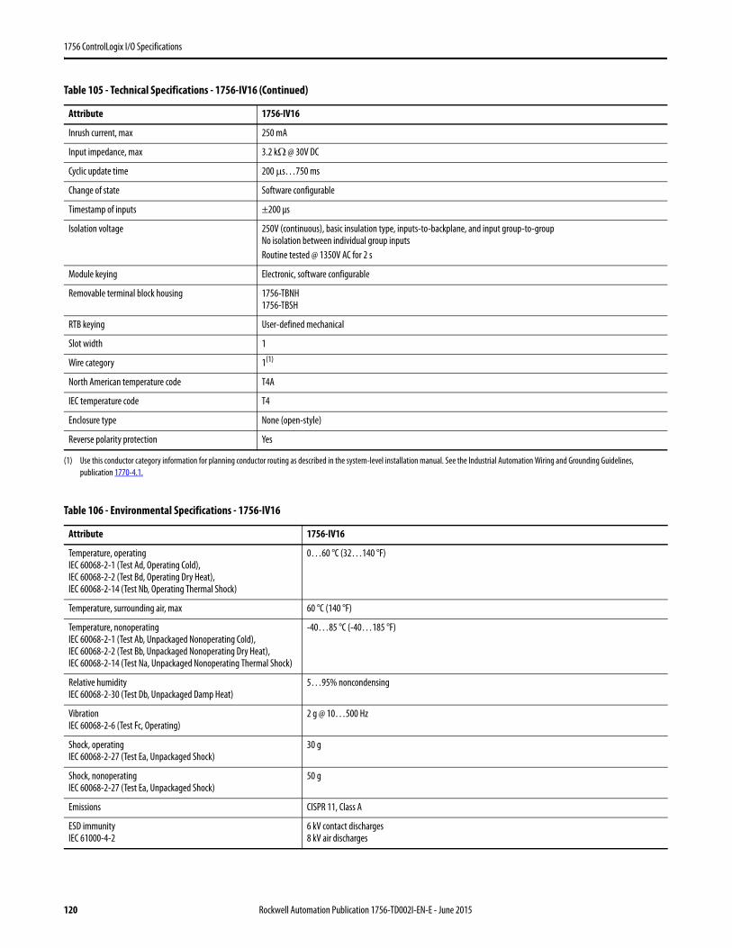
1756 ControlLogix I/O Specifications
Inrush current, max 250 mA
Input impedance, max 3.2 kΩ @ 30V DC
Cyclic update time 200 μs…750 ms
Change of state Software configurable
Timestamp of inputs ±200 μs
Isolation voltage 250V (continuous), basic insulation type, inputs-to-backplane, and input group-to-groupNo isolation between individual group inputsRoutine tested @ 1350V AC for 2 s
Module keying Electronic, software configurable
Removable terminal block housing 1756-TBNH1756-TBSH
RTB keying User-defined mechanical
Slot width 1
Wire category 1(1)
North American temperature code T4A
IEC temperature code T4
Enclosure type None (open-style)
Reverse polarity protection Yes
(1) Use this conductor category information for planning conductor routing as described in the system-level installation manual. See the Industrial Automation Wiring and Grounding Guidelines, publication 1770-4.1.
Table 106 - Environmental Specifications - 1756-IV16
Attribute 1756-IV16
Temperature, operatingIEC 60068-2-1 (Test Ad, Operating Cold),IEC 60068-2-2 (Test Bd, Operating Dry Heat),IEC 60068-2-14 (Test Nb, Operating Thermal Shock)
0…60 °C (32…140 °F)
Temperature, surrounding air, max 60 °C (140 °F)
Temperature, nonoperatingIEC 60068-2-1 (Test Ab, Unpackaged Nonoperating Cold),IEC 60068-2-2 (Test Bb, Unpackaged Nonoperating Dry Heat),IEC 60068-2-14 (Test Na, Unpackaged Nonoperating Thermal Shock)
-40…85 °C (-40…185 °F)
Relative humidityIEC 60068-2-30 (Test Db, Unpackaged Damp Heat)
5…95% noncondensing
VibrationIEC 60068-2-6 (Test Fc, Operating)
2 g @ 10…500 Hz
Shock, operatingIEC 60068-2-27 (Test Ea, Unpackaged Shock)
30 g
Shock, nonoperatingIEC 60068-2-27 (Test Ea, Unpackaged Shock)
50 g
Emissions CISPR 11, Class A
ESD immunityIEC 61000-4-2
6 kV contact discharges8 kV air discharges
Table 105 - Technical Specifications - 1756-IV16 (Continued)
Attribute 1756-IV16
120 Rockwell Automation Publication 1756-TD002I-EN-E - June 2015
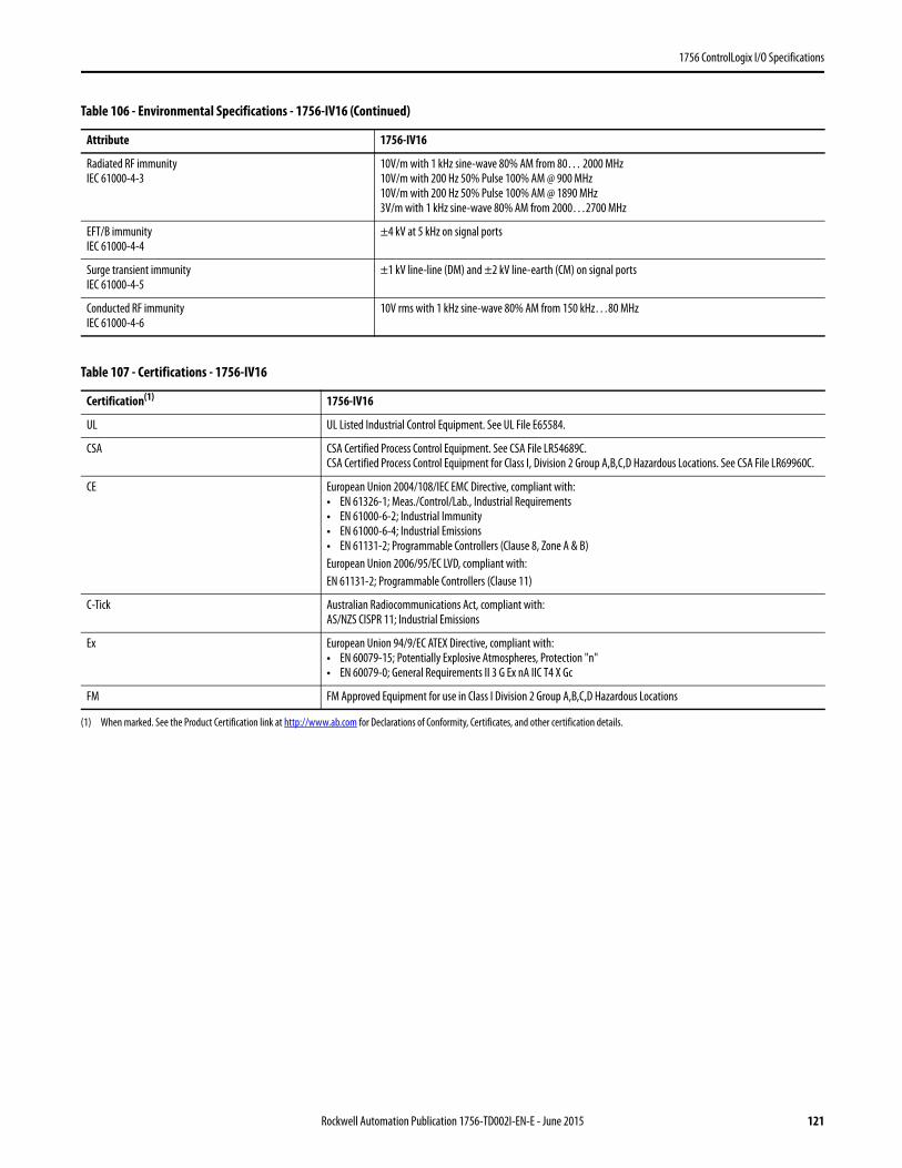
1756 ControlLogix I/O Specifications
Radiated RF immunityIEC 61000-4-3
10V/m with 1 kHz sine-wave 80% AM from 80… 2000 MHz10V/m with 200 Hz 50% Pulse 100% AM @ 900 MHz10V/m with 200 Hz 50% Pulse 100% AM @ 1890 MHz3V/m with 1 kHz sine-wave 80% AM from 2000…2700 MHz
EFT/B immunityIEC 61000-4-4
±4 kV at 5 kHz on signal ports
Surge transient immunityIEC 61000-4-5
±1 kV line-line (DM) and ±2 kV line-earth (CM) on signal ports
Conducted RF immunityIEC 61000-4-6
10V rms with 1 kHz sine-wave 80% AM from 150 kHz…80 MHz
Table 107 - Certifications - 1756-IV16
Certification(1)
(1) When marked. See the Product Certification link at http://www.ab.com for Declarations of Conformity, Certificates, and other certification details.
1756-IV16
UL UL Listed Industrial Control Equipment. See UL File E65584.
CSA CSA Certified Process Control Equipment. See CSA File LR54689C.CSA Certified Process Control Equipment for Class I, Division 2 Group A,B,C,D Hazardous Locations. See CSA File LR69960C.
CE European Union 2004/108/IEC EMC Directive, compliant with:• EN 61326-1; Meas./Control/Lab., Industrial Requirements• EN 61000-6-2; Industrial Immunity• EN 61000-6-4; Industrial Emissions• EN 61131-2; Programmable Controllers (Clause 8, Zone A & B)European Union 2006/95/EC LVD, compliant with:EN 61131-2; Programmable Controllers (Clause 11)
C-Tick Australian Radiocommunications Act, compliant with:AS/NZS CISPR 11; Industrial Emissions
Ex European Union 94/9/EC ATEX Directive, compliant with:• EN 60079-15; Potentially Explosive Atmospheres, Protection "n"• EN 60079-0; General Requirements II 3 G Ex nA IIC T4 X Gc
FM FM Approved Equipment for use in Class I Division 2 Group A,B,C,D Hazardous Locations
Table 106 - Environmental Specifications - 1756-IV16 (Continued)
Attribute 1756-IV16
Rockwell Automation Publication 1756-TD002I-EN-E - June 2015 121
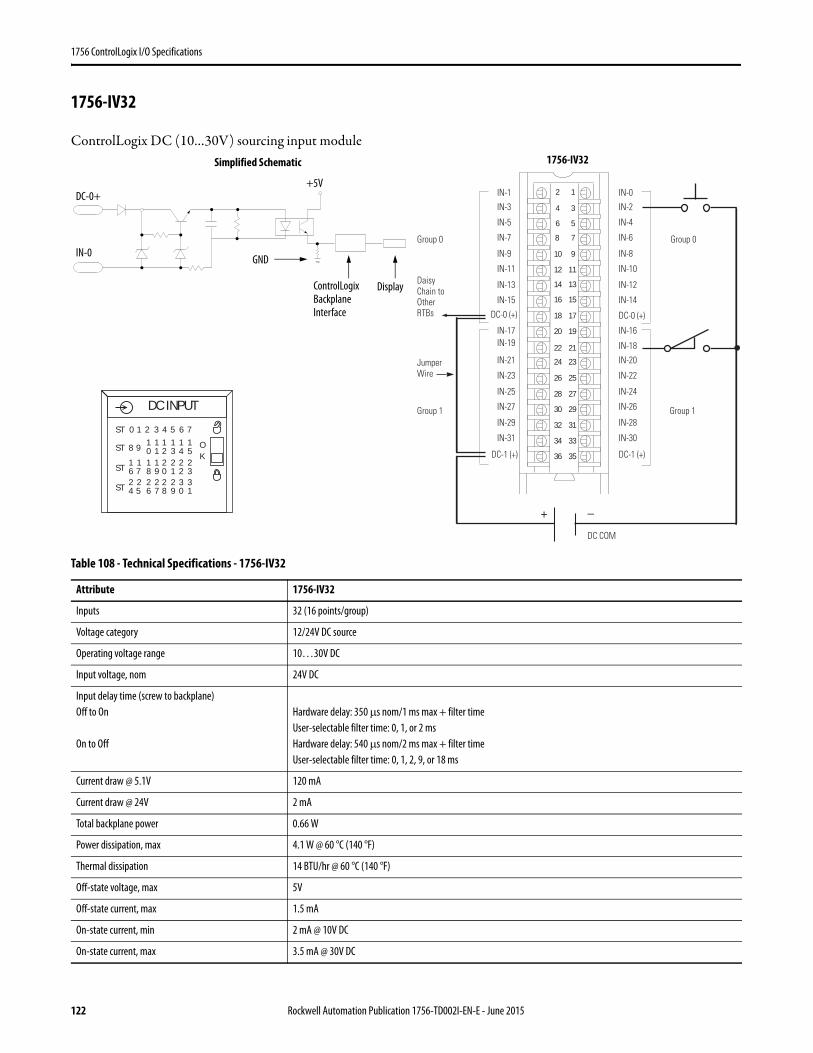
1756 ControlLogix I/O Specifications
1756-IV32
ControlLogix DC (10…30V) sourcing input module
Table 108 - Technical Specifications - 1756-IV32
Attribute 1756-IV32
Inputs 32 (16 points/group)
Voltage category 12/24V DC source
Operating voltage range 10…30V DC
Input voltage, nom 24V DC
Input delay time (screw to backplane)Off to On
On to Off
Hardware delay: 350 μs nom/1 ms max + filter timeUser-selectable filter time: 0, 1, or 2 msHardware delay: 540 μs nom/2 ms max + filter timeUser-selectable filter time: 0, 1, 2, 9, or 18 ms
Current draw @ 5.1V 120 mA
Current draw @ 24V 2 mA
Total backplane power 0.66 W
Power dissipation, max 4.1 W @ 60 °C (140 °F)
Thermal dissipation 14 BTU/hr @ 60 °C (140 °F)
Off-state voltage, max 5V
Off-state current, max 1.5 mA
On-state current, min 2 mA @ 10V DC
On-state current, max 3.5 mA @ 30V DC
12
34
56
78
910
1112
1314
1516
1718
1920
21222324
2526
2728
2930
3132
3334
3536
+ –
Daisy Chain to Other RTBs
DC COM
0 puorG0 puorG
1 puorG1 puorG
IN-1
IN-3
IN-5
IN-7
DC-0 (+)
IN-9
IN-11
IN-13
IN-15
DC-1 (+)
IN-17IN-19
IN-21
IN-23
IN-25
IN-27
IN-29
IN-31
IN-0
IN-2
IN-4
IN-6
DC-0 (+)
IN-8
IN-10
IN-12
IN-14
DC-1 (+)
IN-16
IN-18
IN-20
IN-22
IN-24
IN-26
IN-28
IN-30
Jumper Wire
ControlLogix Backplane Interface
Simplified Schematic
Display
IN-0 GND
DC-0++5V
DC INPUT
OK
ST 0 1 2 3 4 5 6 7
ST 8 9 10 21 3 4 5
1 1 1 11
ST 6 718 09 1 2 3
1 2 2 221 1
ST 4 526 87 9 0 1
2 2 2 332 2
1756-IV32
122 Rockwell Automation Publication 1756-TD002I-EN-E - June 2015

1756 ControlLogix I/O Specifications
Inrush current, max 250 mA (decaying to <37% in 22 ms, without activation)
Input impedance, max 8.6 kΩ @ 30V DC
Cyclic update time 200 μs…750 ms
Change of state Software configurable
Timestamp of inputs ±200 μs
Isolation voltage 250V (continuous), basic insulation type, inputs-to-backplane, and input group-to-groupNo isolation between individual group inputsRoutine tested @ 1350V AC for 2 s
Module keying Electronic, software configurable
Removable terminal block 1756-TBCH1756-TBS6H
RTB keying User-defined mechanical
Slot width 1
Wire category 1 - on signal ports(1)
North American temperature code T4A
IEC temperature code T4
Enclosure type None (open-style)
Reverse polarity protection Yes
(1) Use this conductor category information for planning conductor routing as described in the system-level installation manual. See the Industrial Automation Wiring and Grounding Guidelines, publication 1770-4.1.
Table 109 - Environmental Specifications - 1756-IV32
Attribute 1756-IV32
Temperature, operatingIEC 60068-2-1 (Test Ad, Operating Cold),IEC 60068-2-2 (Test Bd, Operating Dry Heat),IEC 60068-2-14 (Test Nb, Operating Thermal Shock)
0…60 °C (32…140 °F)
Temperature, surrounding air, max 60 °C (140 °F)
Temperature, nonoperatingIEC 60068-2-1 (Test Ab, Unpackaged Nonoperating Cold),IEC 60068-2-2 (Test Bb, Unpackaged Nonoperating Dry Heat),IEC 60068-2-14 (Test Na, Unpackaged Nonoperating Thermal Shock)
-40…85 °C (-40…185 °F)
Relative humidityIEC 60068-2-30 (Test Db, Unpackaged Damp Heat)
5…95% noncondensing
VibrationIEC 60068-2-6 (Test Fc, Operating)
2 g @ 10…500 Hz
Shock, operatingIEC 60068-2-27 (Test Ea, Unpackaged Shock)
30 g
Shock, nonoperatingIEC 60068-2-27 (Test Ea, Unpackaged Shock)
50 g
Emissions CISPR 11, Class A
ESD immunityIEC 61000-4-2
6 kV contact discharges8 kV air discharges
Table 108 - Technical Specifications - 1756-IV32 (Continued)
Attribute 1756-IV32
Rockwell Automation Publication 1756-TD002I-EN-E - June 2015 123
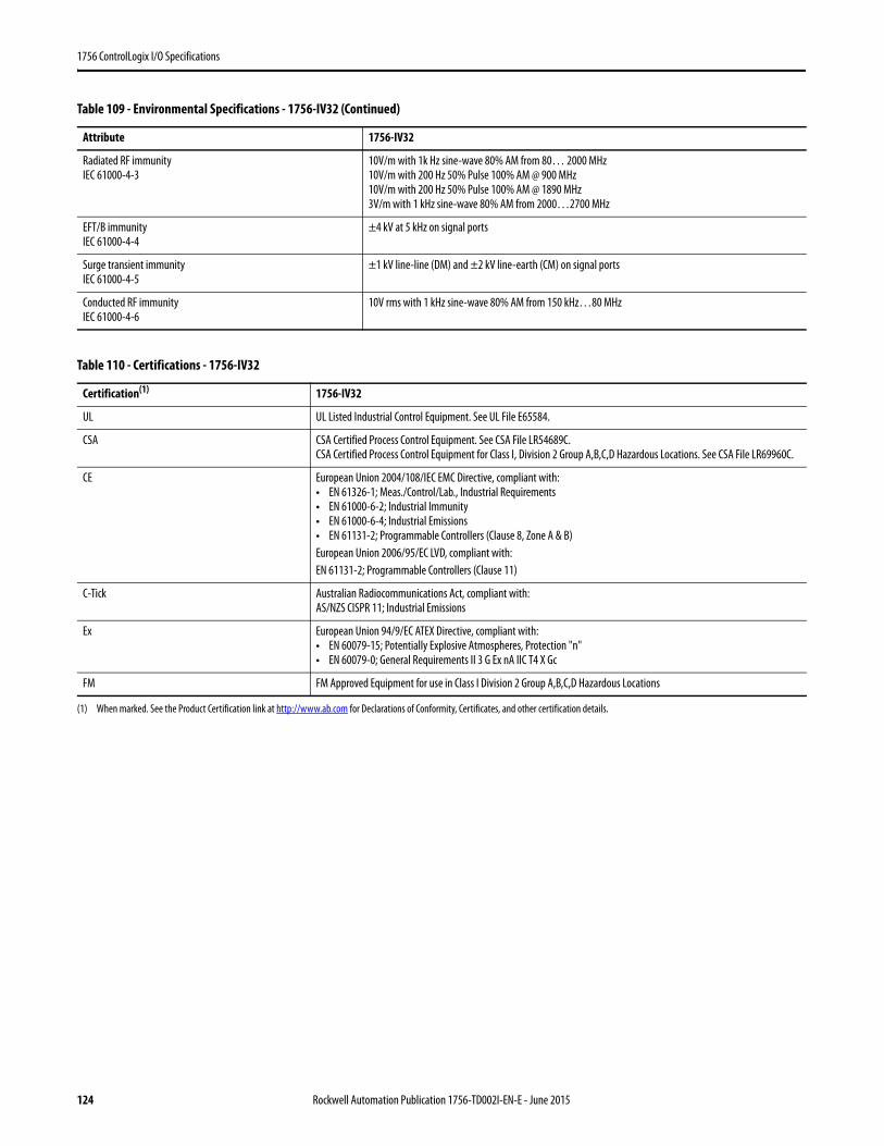
1756 ControlLogix I/O Specifications
Radiated RF immunityIEC 61000-4-3
10V/m with 1k Hz sine-wave 80% AM from 80… 2000 MHz10V/m with 200 Hz 50% Pulse 100% AM @ 900 MHz10V/m with 200 Hz 50% Pulse 100% AM @ 1890 MHz3V/m with 1 kHz sine-wave 80% AM from 2000…2700 MHz
EFT/B immunityIEC 61000-4-4
±4 kV at 5 kHz on signal ports
Surge transient immunityIEC 61000-4-5
±1 kV line-line (DM) and ±2 kV line-earth (CM) on signal ports
Conducted RF immunityIEC 61000-4-6
10V rms with 1 kHz sine-wave 80% AM from 150 kHz…80 MHz
Table 110 - Certifications - 1756-IV32
Certification(1)
(1) When marked. See the Product Certification link at http://www.ab.com for Declarations of Conformity, Certificates, and other certification details.
1756-IV32
UL UL Listed Industrial Control Equipment. See UL File E65584.
CSA CSA Certified Process Control Equipment. See CSA File LR54689C.CSA Certified Process Control Equipment for Class I, Division 2 Group A,B,C,D Hazardous Locations. See CSA File LR69960C.
CE European Union 2004/108/IEC EMC Directive, compliant with:• EN 61326-1; Meas./Control/Lab., Industrial Requirements• EN 61000-6-2; Industrial Immunity• EN 61000-6-4; Industrial Emissions• EN 61131-2; Programmable Controllers (Clause 8, Zone A & B)European Union 2006/95/EC LVD, compliant with:EN 61131-2; Programmable Controllers (Clause 11)
C-Tick Australian Radiocommunications Act, compliant with:AS/NZS CISPR 11; Industrial Emissions
Ex European Union 94/9/EC ATEX Directive, compliant with:• EN 60079-15; Potentially Explosive Atmospheres, Protection "n"• EN 60079-0; General Requirements II 3 G Ex nA IIC T4 X Gc
FM FM Approved Equipment for use in Class I Division 2 Group A,B,C,D Hazardous Locations
Table 109 - Environmental Specifications - 1756-IV32 (Continued)
Attribute 1756-IV32
124 Rockwell Automation Publication 1756-TD002I-EN-E - June 2015
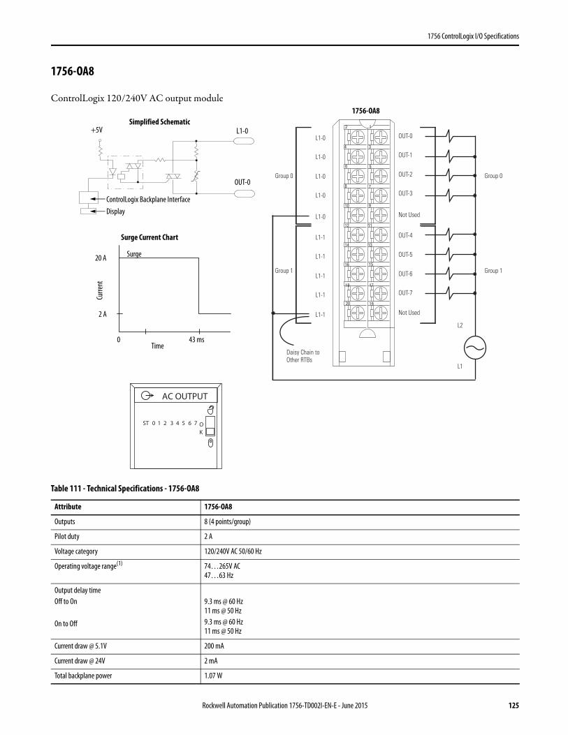
1756 ControlLogix I/O Specifications
1756-OA8
ControlLogix 120/240V AC output module
Table 111 - Technical Specifications - 1756-OA8
Attribute 1756-OA8
Outputs 8 (4 points/group)
Pilot duty 2 A
Voltage category 120/240V AC 50/60 Hz
Operating voltage range(1) 74…265V AC47…63 Hz
Output delay timeOff to On
On to Off
9.3 ms @ 60 Hz11 ms @ 50 Hz 9.3 ms @ 60 Hz11 ms @ 50 Hz
Current draw @ 5.1V 200 mA
Current draw @ 24V 2 mA
Total backplane power 1.07 W
12
34
56
78
910
1112
1314
1516
1718
1920
Daisy Chain to Other RTBs
Group 0Group 0
Group 1Group 1
L2
L1-0
L1-0
L1-0
L1-0
L1-1
L1-1
L1-1
L1-1
L1-0
L1-1
OUT-0
OUT-1
OUT-2
OUT-3
OUT-4
OUT-5
OUT-6
OUT-7
Not Used
Not Used
L1
ControlLogix Backplane Interface
Surge Current Chart
Curre
nt
Display
Simplified Schematic
OUT-0
Time
Surge
+5V L1-0
20 A
2 A
0 43 ms
ST 0 1 2 3 4 5 6 7 OK
AC OUTPUT
1756-OA8
Rockwell Automation Publication 1756-TD002I-EN-E - June 2015 125
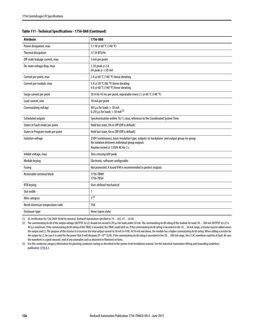
1756 ControlLogix I/O Specifications
Power dissipation, max 5.1 W @ 60 °C (140 °F)
Thermal dissipation 17.39 BTU/hr
Off-state leakage current, max 3 mA per point
On-state voltage drop, max 1.5V peak @ 2 A6V peak @ <50 mA
Current per point, max 2 A @ 60 °C (140 °F) linear derating
Current per module, max 5 A @ 30 °C (86 °F) linear derating4 A @ 60 °C (140 °F) linear derating
Surge current per point 20 A for 43 ms per point, repeatable every 2 s @ 60 °C (140 °F)
Load current, min 10 mA per point
Commutating voltage 4V/μs for loads > 50 mA0.2V/μs for loads < 50 mA(2)
Scheduled outputs Synchronization within 16.7 s max, reference to the Coordinated System Time
States in Fault mode per point Hold last state, On or Off (Off is default)
States in Program mode per point Hold last state, On or Off (Off is default)
Isolation voltage 250V (continuous), basic insulation type, outputs-to-backplane, and output group-to-groupNo isolation between individual group outputsRoutine tested @ 1350V AC for 2 s
Inhibit voltage, max Zero crossing 60V peak
Module keying Electronic, software configurable
Fusing Not protected. A fused IFM is recommended to protect outputs
Removable terminal block 1756-TBNH1756-TBSH
RTB keying User-defined mechanical
Slot width 1
Wire category 1(3)
North American temperature code T4A
Enclosure type None (open style)
(1) UL certification for 120/240V 50/60 Hz nominal. Rockwell Automation specified to 74…265, 47…63 Hz.(2) The commutating dv/dt of the output voltage (OUTPUT to L2) should not exceed 0.2V/µs for loads under 50 mA. The commutating dv/dt rating of the module for loads 50…500 mA (OUTPUT to L2) is
4V/µs maximum. If the commutating dv/dt rating of the TRIAC is exceeded, the TRIAC could latch on. If the commutating dv/dt rating is exceeded in the 10…50 mA range, a resistor may be added across the output and L2. The purpose of this resistor is to increase the total output current to 50 mA (I=V/R). At 50 mA and above, the module has a higher commutating dv/dt rating. When adding a resistor for the output to L2, be sure it is rated for the power that it will dissipate (P=(V**2)/R). If the commutating dv/dt rating is exceeded in the 50…500 mA range, the L1 AC waveform could be at fault. Be sure the waveform is a good sinusoid, void of any anomalies such as distorted or flattened sections.
(3) Use this conductor category information for planning conductor routing as described in the system-level installation manual. See the Industrial Automation Wiring and Grounding Guidelines, publication 1770-4.1.
Table 111 - Technical Specifications - 1756-OA8 (Continued)
Attribute 1756-OA8
126 Rockwell Automation Publication 1756-TD002I-EN-E - June 2015
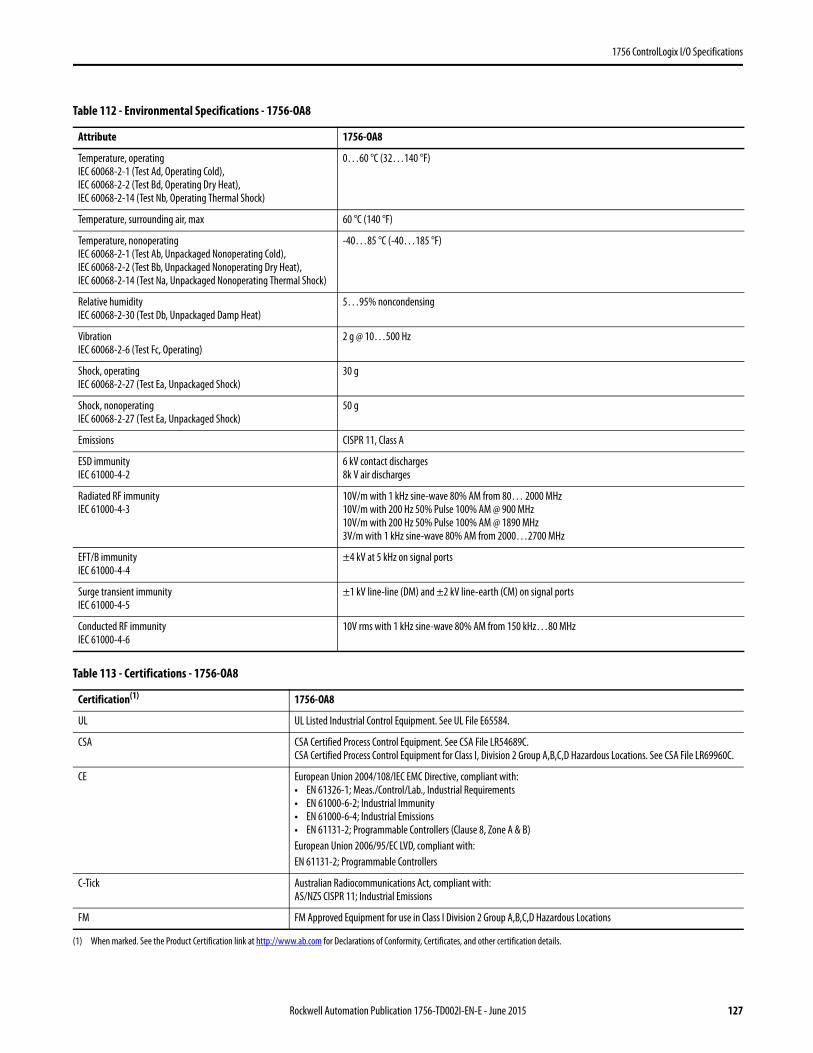
1756 ControlLogix I/O Specifications
Table 112 - Environmental Specifications - 1756-OA8
Attribute 1756-OA8
Temperature, operatingIEC 60068-2-1 (Test Ad, Operating Cold),IEC 60068-2-2 (Test Bd, Operating Dry Heat),IEC 60068-2-14 (Test Nb, Operating Thermal Shock)
0…60 °C (32…140 °F)
Temperature, surrounding air, max 60 °C (140 °F)
Temperature, nonoperatingIEC 60068-2-1 (Test Ab, Unpackaged Nonoperating Cold),IEC 60068-2-2 (Test Bb, Unpackaged Nonoperating Dry Heat),IEC 60068-2-14 (Test Na, Unpackaged Nonoperating Thermal Shock)
-40…85 °C (-40…185 °F)
Relative humidityIEC 60068-2-30 (Test Db, Unpackaged Damp Heat)
5…95% noncondensing
VibrationIEC 60068-2-6 (Test Fc, Operating)
2 g @ 10…500 Hz
Shock, operatingIEC 60068-2-27 (Test Ea, Unpackaged Shock)
30 g
Shock, nonoperatingIEC 60068-2-27 (Test Ea, Unpackaged Shock)
50 g
Emissions CISPR 11, Class A
ESD immunityIEC 61000-4-2
6 kV contact discharges8k V air discharges
Radiated RF immunityIEC 61000-4-3
10V/m with 1 kHz sine-wave 80% AM from 80… 2000 MHz10V/m with 200 Hz 50% Pulse 100% AM @ 900 MHz10V/m with 200 Hz 50% Pulse 100% AM @ 1890 MHz3V/m with 1 kHz sine-wave 80% AM from 2000…2700 MHz
EFT/B immunityIEC 61000-4-4
±4 kV at 5 kHz on signal ports
Surge transient immunityIEC 61000-4-5
±1 kV line-line (DM) and ±2 kV line-earth (CM) on signal ports
Conducted RF immunityIEC 61000-4-6
10V rms with 1 kHz sine-wave 80% AM from 150 kHz…80 MHz
Table 113 - Certifications - 1756-OA8
Certification(1)
(1) When marked. See the Product Certification link at http://www.ab.com for Declarations of Conformity, Certificates, and other certification details.
1756-OA8
UL UL Listed Industrial Control Equipment. See UL File E65584.
CSA CSA Certified Process Control Equipment. See CSA File LR54689C.CSA Certified Process Control Equipment for Class I, Division 2 Group A,B,C,D Hazardous Locations. See CSA File LR69960C.
CE European Union 2004/108/IEC EMC Directive, compliant with:• EN 61326-1; Meas./Control/Lab., Industrial Requirements• EN 61000-6-2; Industrial Immunity• EN 61000-6-4; Industrial Emissions• EN 61131-2; Programmable Controllers (Clause 8, Zone A & B)European Union 2006/95/EC LVD, compliant with:EN 61131-2; Programmable Controllers
C-Tick Australian Radiocommunications Act, compliant with:AS/NZS CISPR 11; Industrial Emissions
FM FM Approved Equipment for use in Class I Division 2 Group A,B,C,D Hazardous Locations
Rockwell Automation Publication 1756-TD002I-EN-E - June 2015 127
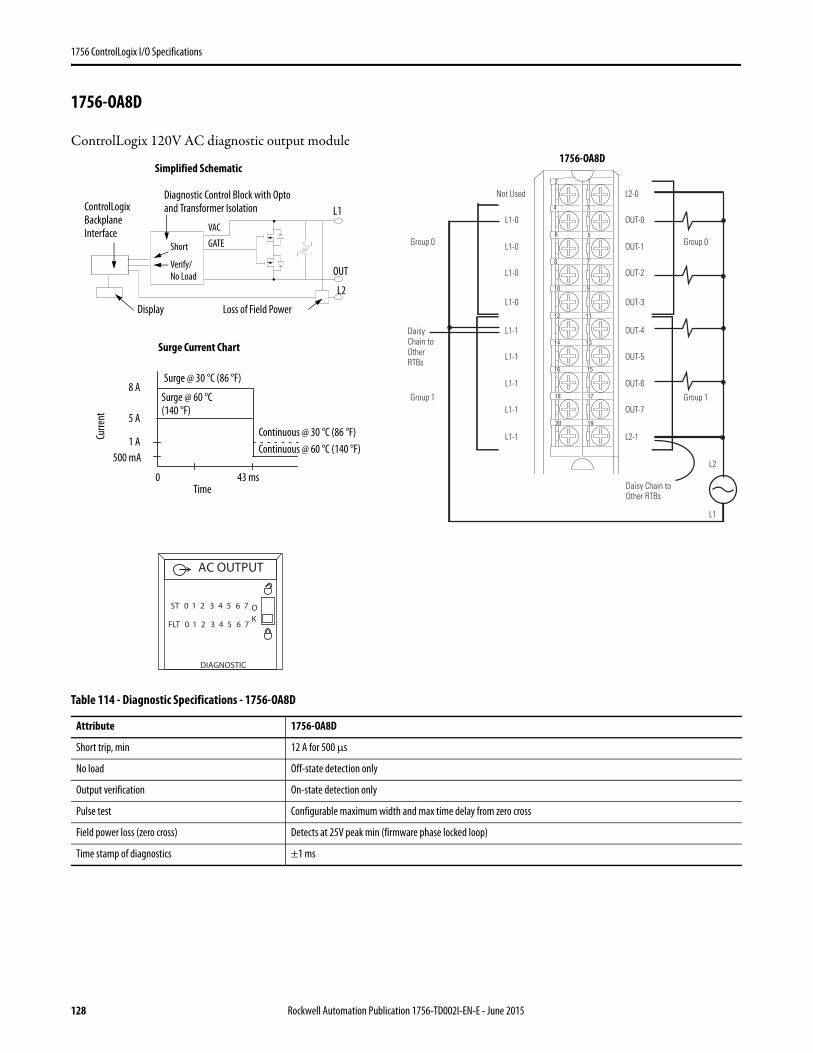
1756 ControlLogix I/O Specifications
1756-OA8D
ControlLogix 120V AC diagnostic output module
Table 114 - Diagnostic Specifications - 1756-OA8D
Attribute 1756-OA8D
Short trip, min 12 A for 500 μs
No load Off-state detection only
Output verification On-state detection only
Pulse test Configurable maximum width and max time delay from zero cross
Field power loss (zero cross) Detects at 25V peak min (firmware phase locked loop)
Time stamp of diagnostics ±1 ms
12
34
56
78
910
1112
1314
1516
1718
1920
Daisy Chain to Other RTBs
Daisy Chain to Other RTBs
Group 0Group 0
Group 1Group 1
L2
Not Used
L1-0
L1-0
L1-0
L1-1
L1-1
L1-1
L1-1
L1-0
L1-1
L2-0
OUT-0
OUT-1
OUT-2
OUT-4
OUT-5
OUT-6
OUT-7
OUT-3
L2-1
L1
ControlLogix Backplane Interface
Diagnostic Control Block with Opto and Transformer Isolation
Surge Current Chart
Continuous @ 30 °C (86 °F)Curre
nt
Display
Simplified Schematic
OUT
L1
Continuous @ 60 °C (140 °F)
Time
Surge @ 30 °C (86 °F)
Surge @ 60 °C(140 °F)
Loss of Field Power
Short
Verify/No Load
VAC
GATE
L2
500 mA
0 43 ms
1 A
5 A
8 A
DIAGNOSTIC
ST 0 1 2 3 4 5 6 7 OK
AC OUTPUT
FLT 0 1 2 3 4 5 6 7
1756-OA8D
128 Rockwell Automation Publication 1756-TD002I-EN-E - June 2015
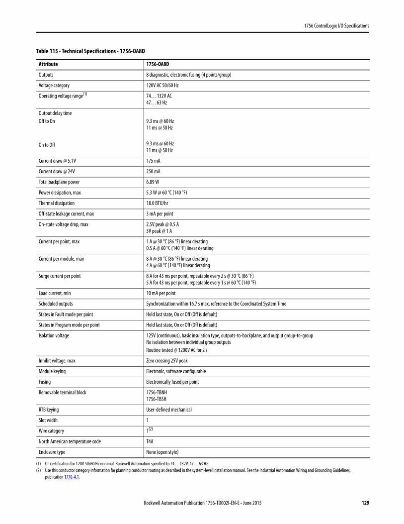
1756 ControlLogix I/O Specifications
Table 115 - Technical Specifications - 1756-OA8D
Attribute 1756-OA8D
Outputs 8 diagnostic, electronic fusing (4 points/group)
Voltage category 120V AC 50/60 Hz
Operating voltage range(1)
(1) UL certification for 120V 50/60 Hz nominal. Rockwell Automation specified to 74…132V, 47…63 Hz.
74…132V AC47…63 Hz
Output delay timeOff to On
On to Off
9.3 ms @ 60 Hz11 ms @ 50 Hz
9.3 ms @ 60 Hz11 ms @ 50 Hz
Current draw @ 5.1V 175 mA
Current draw @ 24V 250 mA
Total backplane power 6.89 W
Power dissipation, max 5.3 W @ 60 °C (140 °F)
Thermal dissipation 18.0 BTU/hr
Off-state leakage current, max 3 mA per point
On-state voltage drop, max 2.5V peak @ 0.5 A3V peak @ 1 A
Current per point, max 1 A @ 30 °C (86 °F) linear derating0.5 A @ 60 °C (140 °F) linear derating
Current per module, max 8 A @ 30 °C (86 °F) linear derating4 A @ 60 °C (140 °F) linear derating
Surge current per point 8 A for 43 ms per point, repeatable every 2 s @ 30 °C (86 °F)5 A for 43 ms per point, repeatable every 1 s @ 60 °C (140 °F)
Load current, min 10 mA per point
Scheduled outputs Synchronization within 16.7 s max, reference to the Coordinated System Time
States in Fault mode per point Hold last state, On or Off (Off is default)
States in Program mode per point Hold last state, On or Off (Off is default)
Isolation voltage 125V (continuous), basic insulation type, outputs-to-backplane, and output group-to-groupNo isolation between individual group outputsRoutine tested @ 1200V AC for 2 s
Inhibit voltage, max Zero crossing 25V peak
Module keying Electronic, software configurable
Fusing Electronically fused per point
Removable terminal block 1756-TBNH1756-TBSH
RTB keying User-defined mechanical
Slot width 1
Wire category 1(2)
(2) Use this conductor category information for planning conductor routing as described in the system-level installation manual. See the Industrial Automation Wiring and Grounding Guidelines, publication 1770-4.1.
North American temperature code T4A
Enclosure type None (open style)
Rockwell Automation Publication 1756-TD002I-EN-E - June 2015 129
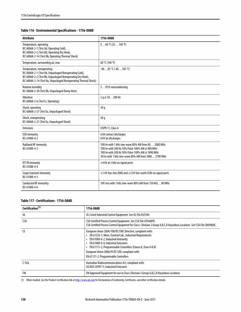
1756 ControlLogix I/O Specifications
Table 116 - Environmental Specifications - 1756-OA8D
Attribute 1756-OA8D
Temperature, operatingIEC 60068-2-1 (Test Ad, Operating Cold),IEC 60068-2-2 (Test Bd, Operating Dry Heat),IEC 60068-2-14 (Test Nb, Operating Thermal Shock)
0…60 °C (32…140 °F)
Temperature, surrounding air, max 60 °C (140 °F)
Temperature, nonoperatingIEC 60068-2-1 (Test Ab, Unpackaged Nonoperating Cold),IEC 60068-2-2 (Test Bb, Unpackaged Nonoperating Dry Heat),IEC 60068-2-14 (Test Na, Unpackaged Nonoperating Thermal Shock)
-40…85 °C (-40…185 °F)
Relative humidityIEC 60068-2-30 (Test Db, Unpackaged Damp Heat)
5…95% noncondensing
VibrationIEC 60068-2-6 (Test Fc, Operating)
2 g @ 10…500 Hz
Shock, operatingIEC 60068-2-27 (Test Ea, Unpackaged Shock)
30 g
Shock, nonoperatingIEC 60068-2-27 (Test Ea, Unpackaged Shock)
50 g
Emissions CISPR 11, Class A
ESD immunityIEC 61000-4-2
6 kV contact discharges8 kV air discharges
Radiated RF immunityIEC 61000-4-3
10V/m with 1 kHz sine-wave 80% AM from 80… 2000 MHz10V/m with 200 Hz 50% Pulse 100% AM @ 900 MHz10V/m with 200 Hz 50% Pulse 100% AM @ 1890 MHz3V/m with 1 kHz sine-wave 80% AM from 2000…2700 MHz
EFT/B immunityIEC 61000-4-4
±4 kV at 5 kHz on signal ports
Surge transient immunityIEC 61000-4-5
±1 kV line-line (DM) and ±2 kV line-earth (CM) on signal ports
Conducted RF immunityIEC 61000-4-6
10V rms with 1 kHz sine-wave 80% AM from 150 kHz…80 MHz
Table 117 - Certifications - 1756-OA8D
Certification(1)
(1) When marked. See the Product Certification link at http://www.ab.com for Declarations of Conformity, Certificates, and other certification details.
1756-OA8D
UL UL Listed Industrial Control Equipment. See UL File E65584.
CSA CSA Certified Process Control Equipment. See CSA File LR54689C.CSA Certified Process Control Equipment for Class I, Division 2 Group A,B,C,D Hazardous Locations. See CSA File LR69960C.
CE European Union 2004/108/IEC EMC Directive, compliant with:• EN 61326-1; Meas./Control/Lab., Industrial Requirements• EN 61000-6-2; Industrial Immunity• EN 61000-6-4; Industrial Emissions• EN 61131-2; Programmable Controllers (Clause 8, Zone A & B)European Union 2006/95/EC LVD, compliant with:EN 61131-2; Programmable Controllers
C-Tick Australian Radiocommunications Act, compliant with:AS/NZS CISPR 11; Industrial Emissions
FM FM Approved Equipment for use in Class I Division 2 Group A,B,C,D Hazardous Locations
130 Rockwell Automation Publication 1756-TD002I-EN-E - June 2015
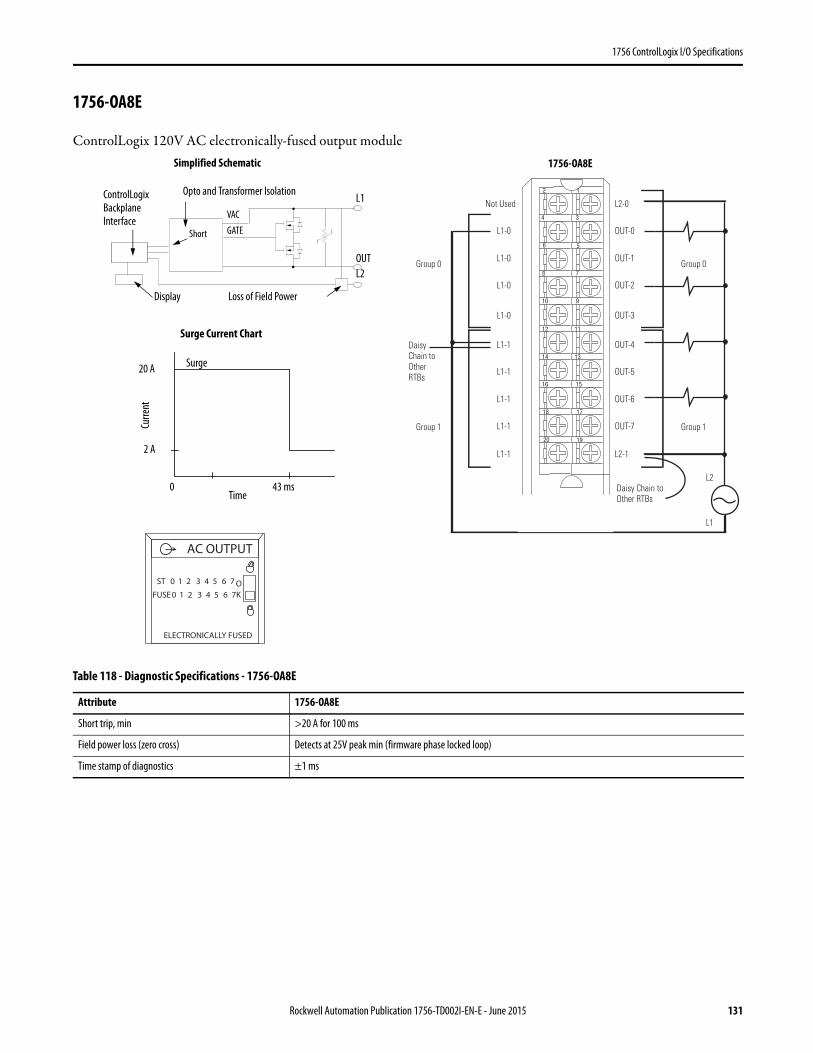
1756 ControlLogix I/O Specifications
1756-OA8E
ControlLogix 120V AC electronically-fused output module
Table 118 - Diagnostic Specifications - 1756-OA8E
Attribute 1756-OA8E
Short trip, min >20 A for 100 ms
Field power loss (zero cross) Detects at 25V peak min (firmware phase locked loop)
Time stamp of diagnostics ±1 ms
12
34
56
78
910
1112
1314
1516
1718
1920
Daisy Chain to Other RTBs
Group 0Group 0
Group 1Group 1
L2
Not Used
L1-0
L1-0
L1-0
L1-1
L1-1
L1-1
L1-1
L1-0
L1-1
L2-0
OUT-0
OUT-1
OUT-2
OUT-4
OUT-5
OUT-6
OUT-7
OUT-3
L2-1
Daisy Chain to Other RTBs
L1
ControlLogix Backplane Interface
Opto and Transformer Isolation
Surge Current Chart
Display
Simplified Schematic
OUT
L1
Time
Surge
Loss of Field Power
Short
VAC
GATE
0 43 ms
Curre
nt
20 A
2 A
L2
ST 0 1 2 3 4 5 6 7
FUSE 0 1 2 3 4 5 6 7OK
AC OUTPUT
ELECTRONICALLY FUSED
1756-OA8E
Rockwell Automation Publication 1756-TD002I-EN-E - June 2015 131

1756 ControlLogix I/O Specifications
Table 119 - Technical Specifications - 1756-OA8E
Attribute 1756-OA8E
Outputs 8 electronic fusing (4 points/group)
Pilot duty Yes
Voltage category 120V AC 50/60 Hz
Operating voltage range(1) 74…132V AC47…63 Hz
Output delay timeOff to On
On to Off
9.3 ms @ 60 Hz11 ms @ 50 Hz
9.3 ms @ 60 Hz11 ms @ 50 Hz
Current draw @ 5.1V 200 mA
Current draw @ 24V 250 mA
Total backplane power 7.02 W
Power dissipation, max 5.5 W @ 60 °C (140 °F)
Thermal dissipation 18.76 BTU/hr
Off-state leakage current, max 3 mA per point
On-state voltage drop, max 4V peak @ 2 A
Current per point, max 2 A @ 60 °C (140 °F)
Current per group, max 4 A @ 30 °C (86 °F) linear derating2 A @ 60 °C (140 °F) linear derating
Current per module, max 8 A @ 30 °C (86 °F) linear derating4 A @ 60 °C (140 °F) linear derating
Surge current per point 20 A for 43 ms per point, repeatable every 2 s @ 60 °C (140 °F)
Load current, min 10 mA per point
Scheduled outputs Synchronization within 16.7 s max, reference to the Coordinated System Time
States in Fault mode per point Hold last state, On or Off (Off is default)
States in Program mode per point Hold last state, On or Off (Off is default)
Isolation voltage 125V (continuous), basic insulation type, outputs-to-backplane, and output group-to-groupNo isolation between individual group outputsRoutine tested @ 1200V AC for 2 s
Inhibit voltage, max Zero crossing 25V peak
Module keying Electronic, software configurable
Fusing Electronically fused per point
Removable terminal block 1756-TBNH1756-TBSH
RTB keying User-defined mechanical
Slot width 1
Wire category 1(2)
North American temperature code T4A
Enclosure type None (open style)
(1) UL certification for 120V 50/60Hz nominal. Rockwell Automation specified to 74…132V, 47…63 Hz.(2) Use this conductor category information for planning conductor routing as described in the system-level installation manual. See the Industrial Automation Wiring and Grounding Guidelines,
publication 1770-4.1.
132 Rockwell Automation Publication 1756-TD002I-EN-E - June 2015
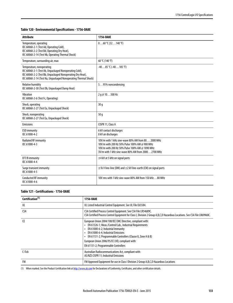
1756 ControlLogix I/O Specifications
Table 120 - Environmental Specifications - 1756-OA8E
Attribute 1756-OA8E
Temperature, operatingIEC 60068-2-1 (Test Ad, Operating Cold),IEC 60068-2-2 (Test Bd, Operating Dry Heat),IEC 60068-2-14 (Test Nb, Operating Thermal Shock)
0…60 °C (32…140 °F)
Temperature, surrounding air, max 60 °C (140 °F)
Temperature, nonoperatingIEC 60068-2-1 (Test Ab, Unpackaged Nonoperating Cold),IEC 60068-2-2 (Test Bb, Unpackaged Nonoperating Dry Heat),IEC 60068-2-14 (Test Na, Unpackaged Nonoperating Thermal Shock)
-40…85 °C (-40…185 °F)
Relative humidityIEC 60068-2-30 (Test Db, Unpackaged Damp Heat)
5…95% noncondensing
VibrationIEC 60068-2-6 (Test Fc, Operating)
2 g @ 10…500 Hz
Shock, operatingIEC 60068-2-27 (Test Ea, Unpackaged Shock)
30 g
Shock, nonoperatingIEC 60068-2-27 (Test Ea, Unpackaged Shock)
50 g
Emissions CISPR 11, Class A
ESD immunityIEC 61000-4-2
6 kV contact discharges8 kV air discharges
Radiated RF immunityIEC 61000-4-3
10V/m with 1 kHz sine-wave 80% AM from 80… 2000 MHz10V/m with 200 Hz 50% Pulse 100% AM @ 900 MHz10V/m with 200 Hz 50% Pulse 100% AM @ 1890 MHz3V/m with 1 kHz sine-wave 80% AM from 2000…2700 MHz
EFT/B immunityIEC 61000-4-4
±4 kV at 5 kHz on signal ports
Surge transient immunityIEC 61000-4-5
±1k V line-line (DM) and ±2 kV line-earth (CM) on signal ports
Conducted RF immunityIEC 61000-4-6
10V rms with 1 kHz sine-wave 80% AM from 150 kHz…80 MHz
Table 121 - Certifications - 1756-OA8E
Certification(1)
(1) When marked. See the Product Certification link at http://www.ab.com for Declarations of Conformity, Certificates, and other certification details.
1756-OA8E
UL UL Listed Industrial Control Equipment. See UL File E65584.
CSA CSA Certified Process Control Equipment. See CSA File LR54689C.CSA Certified Process Control Equipment for Class I, Division 2 Group A,B,C,D Hazardous Locations. See CSA File LR69960C.
CE European Union 2004/108/IEC EMC Directive, compliant with:• EN 61326-1; Meas./Control/Lab., Industrial Requirements• EN 61000-6-2; Industrial Immunity• EN 61000-6-4; Industrial Emissions• EN 61131-2; Programmable Controllers (Clause 8, Zone A & B)European Union 2006/95/EC LVD, compliant with:EN 61131-2; Programmable Controllers
C-Tick Australian Radiocommunications Act, compliant with:AS/NZS CISPR 11; Industrial Emissions
FM FM Approved Equipment for use in Class I Division 2 Group A,B,C,D Hazardous Locations
Rockwell Automation Publication 1756-TD002I-EN-E - June 2015 133
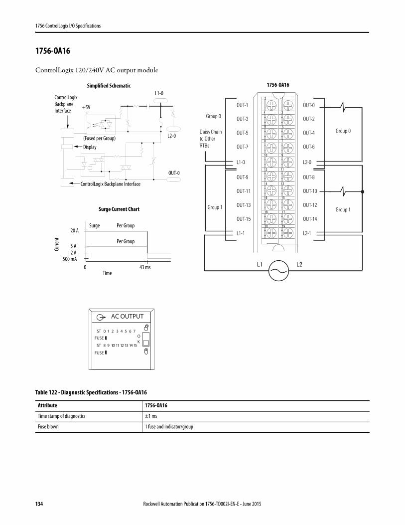
1756 ControlLogix I/O Specifications
1756-OA16
ControlLogix 120/240V AC output module
Table 122 - Diagnostic Specifications - 1756-OA16
Attribute 1756-OA16
Time stamp of diagnostics ±1 ms
Fuse blown 1 fuse and indicator/group
L1
12
34
56
78
910
1112
1314
1516
1718
1920
L1 L2
Daisy Chain to Other RTBs
Group 0
Group 0
Group 1 Group 1
OUT-1
OUT-3
OUT-5
OUT-7
OUT-9
OUT-11
OUT-13
OUT-15
L1-0
L1-1
OUT-0
OUT-2
OUT-4
OUT-6
OUT-8
OUT-10
OUT-12
OUT-14
L2-0
L2-1
ControlLogix Backplane Interface
ControlLogix Backplane Interface
(Fused per Group)
Simplified Schematic
Per Group
Surge Current Chart
Per Group
Surge
Display
L1-0
OUT-0
Curre
nt
Time
500 mA0 43 ms
2 A5 A
20 A
+5V
AC OUTPUT
ST 0 1 2 3 4 5 6 7
ST 8 9 10 11 12 13 14 15
OK
FUSE
FUSE
L2-0
1756-OA16
134 Rockwell Automation Publication 1756-TD002I-EN-E - June 2015
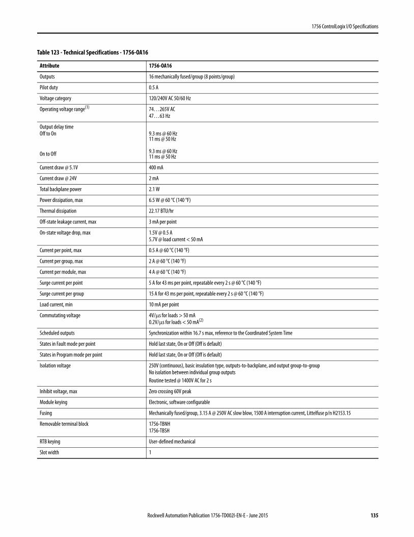
1756 ControlLogix I/O Specifications
Table 123 - Technical Specifications - 1756-OA16
Attribute 1756-OA16
Outputs 16 mechanically fused/group (8 points/group)
Pilot duty 0.5 A
Voltage category 120/240V AC 50/60 Hz
Operating voltage range(1) 74…265V AC47…63 Hz
Output delay timeOff to On
On to Off
9.3 ms @ 60 Hz11 ms @ 50 Hz
9.3 ms @ 60 Hz11 ms @ 50 Hz
Current draw @ 5.1V 400 mA
Current draw @ 24V 2 mA
Total backplane power 2.1 W
Power dissipation, max 6.5 W @ 60 °C (140 °F)
Thermal dissipation 22.17 BTU/hr
Off-state leakage current, max 3 mA per point
On-state voltage drop, max 1.5V @ 0.5 A5.7V @ load current < 50 mA
Current per point, max 0.5 A @ 60 °C (140 °F)
Current per group, max 2 A @ 60 °C (140 °F)
Current per module, max 4 A @ 60 °C (140 °F)
Surge current per point 5 A for 43 ms per point, repeatable every 2 s @ 60 °C (140 °F)
Surge current per group 15 A for 43 ms per point, repeatable every 2 s @ 60 °C (140 °F)
Load current, min 10 mA per point
Commutating voltage 4V/μs for loads > 50 mA0.2V/μs for loads < 50 mA(2)
Scheduled outputs Synchronization within 16.7 s max, reference to the Coordinated System Time
States in Fault mode per point Hold last state, On or Off (Off is default)
States in Program mode per point Hold last state, On or Off (Off is default)
Isolation voltage 250V (continuous), basic insulation type, outputs-to-backplane, and output group-to-groupNo isolation between individual group outputsRoutine tested @ 1400V AC for 2 s
Inhibit voltage, max Zero crossing 60V peak
Module keying Electronic, software configurable
Fusing Mechanically fused/group, 3.15 A @ 250V AC slow blow, 1500 A interruption current, Littelfuse p/n H2153.15
Removable terminal block 1756-TBNH1756-TBSH
RTB keying User-defined mechanical
Slot width 1
Rockwell Automation Publication 1756-TD002I-EN-E - June 2015 135
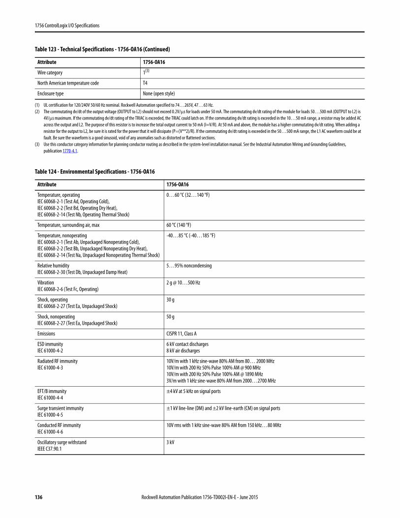
1756 ControlLogix I/O Specifications
Wire category 1(3)
North American temperature code T4
Enclosure type None (open style)
(1) UL certification for 120/240V 50/60 Hz nominal. Rockwell Automation specified to 74…265V, 47…63 Hz.(2) The commutating dv/dt of the output voltage (OUTPUT to L2) should not exceed 0.2V/µs for loads under 50 mA. The commutating dv/dt rating of the module for loads 50…500 mA (OUTPUT to L2) is
4V/µs maximum. If the commutating dv/dt rating of the TRIAC is exceeded, the TRIAC could latch on. If the commutating dv/dt rating is exceeded in the 10…50 mA range, a resistor may be added AC across the output and L2. The purpose of this resistor is to increase the total output current to 50 mA (I=V/R). At 50 mA and above, the module has a higher commutating dv/dt rating. When adding a resistor for the output to L2, be sure it is rated for the power that it will dissipate (P=(V**2)/R). If the commutating dv/dt rating is exceeded in the 50…500 mA range, the L1 AC waveform could be at fault. Be sure the waveform is a good sinusoid, void of any anomalies such as distorted or flattened sections.
(3) Use this conductor category information for planning conductor routing as described in the system-level installation manual. See the Industrial Automation Wiring and Grounding Guidelines, publication 1770-4.1.
Table 124 - Environmental Specifications - 1756-OA16
Attribute 1756-OA16
Temperature, operatingIEC 60068-2-1 (Test Ad, Operating Cold),IEC 60068-2-2 (Test Bd, Operating Dry Heat),IEC 60068-2-14 (Test Nb, Operating Thermal Shock)
0…60 °C (32…140 °F)
Temperature, surrounding air, max 60 °C (140 °F)
Temperature, nonoperatingIEC 60068-2-1 (Test Ab, Unpackaged Nonoperating Cold),IEC 60068-2-2 (Test Bb, Unpackaged Nonoperating Dry Heat),IEC 60068-2-14 (Test Na, Unpackaged Nonoperating Thermal Shock)
-40…85 °C (-40…185 °F)
Relative humidityIEC 60068-2-30 (Test Db, Unpackaged Damp Heat)
5…95% noncondensing
VibrationIEC 60068-2-6 (Test Fc, Operating)
2 g @ 10…500 Hz
Shock, operatingIEC 60068-2-27 (Test Ea, Unpackaged Shock)
30 g
Shock, nonoperatingIEC 60068-2-27 (Test Ea, Unpackaged Shock)
50 g
Emissions CISPR 11, Class A
ESD immunityIEC 61000-4-2
6 kV contact discharges8 kV air discharges
Radiated RF immunityIEC 61000-4-3
10V/m with 1 kHz sine-wave 80% AM from 80… 2000 MHz10V/m with 200 Hz 50% Pulse 100% AM @ 900 MHz10V/m with 200 Hz 50% Pulse 100% AM @ 1890 MHz3V/m with 1 kHz sine-wave 80% AM from 2000…2700 MHz
EFT/B immunityIEC 61000-4-4
±4 kV at 5 kHz on signal ports
Surge transient immunityIEC 61000-4-5
±1 kV line-line (DM) and ±2 kV line-earth (CM) on signal ports
Conducted RF immunityIEC 61000-4-6
10V rms with 1 kHz sine-wave 80% AM from 150 kHz…80 MHz
Oscillatory surge withstandIEEE C37.90.1
3 kV
Table 123 - Technical Specifications - 1756-OA16 (Continued)
Attribute 1756-OA16
136 Rockwell Automation Publication 1756-TD002I-EN-E - June 2015
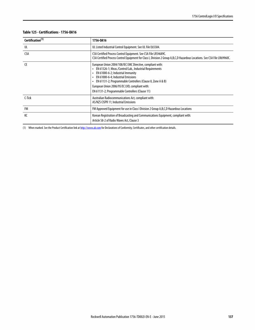
1756 ControlLogix I/O Specifications
Table 125 - Certifications - 1756-OA16
Certification(1)
(1) When marked. See the Product Certification link at http://www.ab.com for Declarations of Conformity, Certificates, and other certification details.
1756-OA16
UL UL Listed Industrial Control Equipment. See UL File E65584.
CSA CSA Certified Process Control Equipment. See CSA File LR54689C.CSA Certified Process Control Equipment for Class I, Division 2 Group A,B,C,D Hazardous Locations. See CSA File LR69960C.
CE European Union 2004/108/IEC EMC Directive, compliant with:• EN 61326-1; Meas./Control/Lab., Industrial Requirements• EN 61000-6-2; Industrial Immunity• EN 61000-6-4; Industrial Emissions• EN 61131-2; Programmable Controllers (Clause 8, Zone A & B)European Union 2006/95/EC LVD, compliant with:EN 61131-2; Programmable Controllers (Clause 11)
C-Tick Australian Radiocommunications Act, compliant with:AS/NZS CISPR 11; Industrial Emissions
FM FM Approved Equipment for use in Class I Division 2 Group A,B,C,D Hazardous Locations
KC Korean Registration of Broadcasting and Communications Equipment, compliant with:Article 58-2 of Radio Waves Act, Clause 3
Rockwell Automation Publication 1756-TD002I-EN-E - June 2015 137
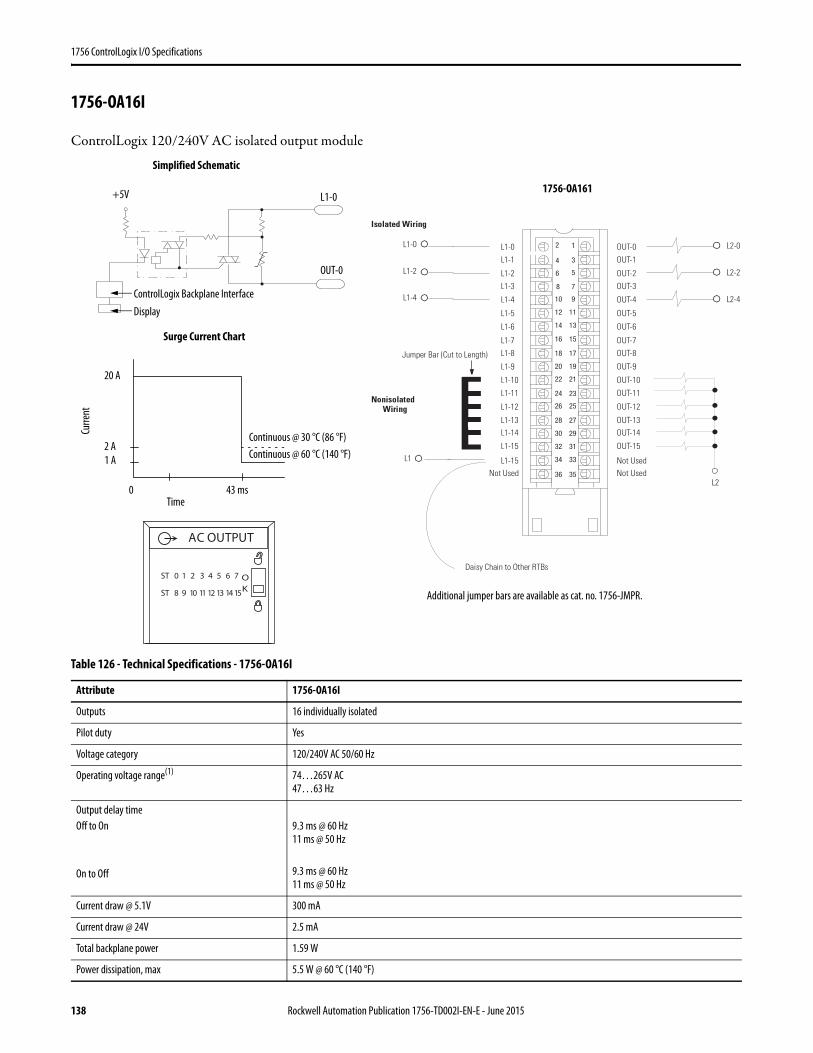
1756 ControlLogix I/O Specifications
1756-OA16I
ControlLogix 120/240V AC isolated output module
Table 126 - Technical Specifications - 1756-OA16I
Attribute 1756-OA16I
Outputs 16 individually isolated
Pilot duty Yes
Voltage category 120/240V AC 50/60 Hz
Operating voltage range(1) 74…265V AC47…63 Hz
Output delay timeOff to On
On to Off
9.3 ms @ 60 Hz11 ms @ 50 Hz
9.3 ms @ 60 Hz11 ms @ 50 Hz
Current draw @ 5.1V 300 mA
Current draw @ 24V 2.5 mA
Total backplane power 1.59 W
Power dissipation, max 5.5 W @ 60 °C (140 °F)
1
3
5
7
01 9
21 11
41 31
61 51
81 71
02 91
22 12
42 32
62 52
82 72
03 92
23 13
43 33
63 53
Nonisolated Wiring
Isolated Wiring
Daisy Chain to Other RTBs
L1-0 L1-0
L1-1
L1-2
L1-3
L1-8
L1-4
L1-5
L1-6
L1-7
Not Used
L1-9
L1-10
L1-11
L1-12
L1-13L1-14
L1-15
L1-15
OUT-0
OUT-1
OUT-2
OUT-3
OUT-8
OUT-4
OUT-5
OUT-6
OUT-7
Not Used
OUT-9
OUT-10
OUT-11
OUT-12
OUT-13OUT-14
OUT-15
Not Used
L1-2
L1-4
L1
L2
L2-0
L2-2
L2-4
Jumper Bar (Cut to Length)
2
4
8
6
ControlLogix Backplane Interface
Surge Current Chart
Continuous @ 30 °C (86 °F)
Display
Simplified Schematic
OUT-0
L1-0
Continuous @ 60 °C (140 °F)
Curre
nt
Time
1 A
0 43 ms
2 A
20 A
+5V
Additional jumper bars are available as cat. no. 1756-JMPR.
ST 0 1 2 3 4 5 6 7
ST 8 9 10 11 12 13 14 15
OK
AC OUTPUT
1756-OA161
138 Rockwell Automation Publication 1756-TD002I-EN-E - June 2015
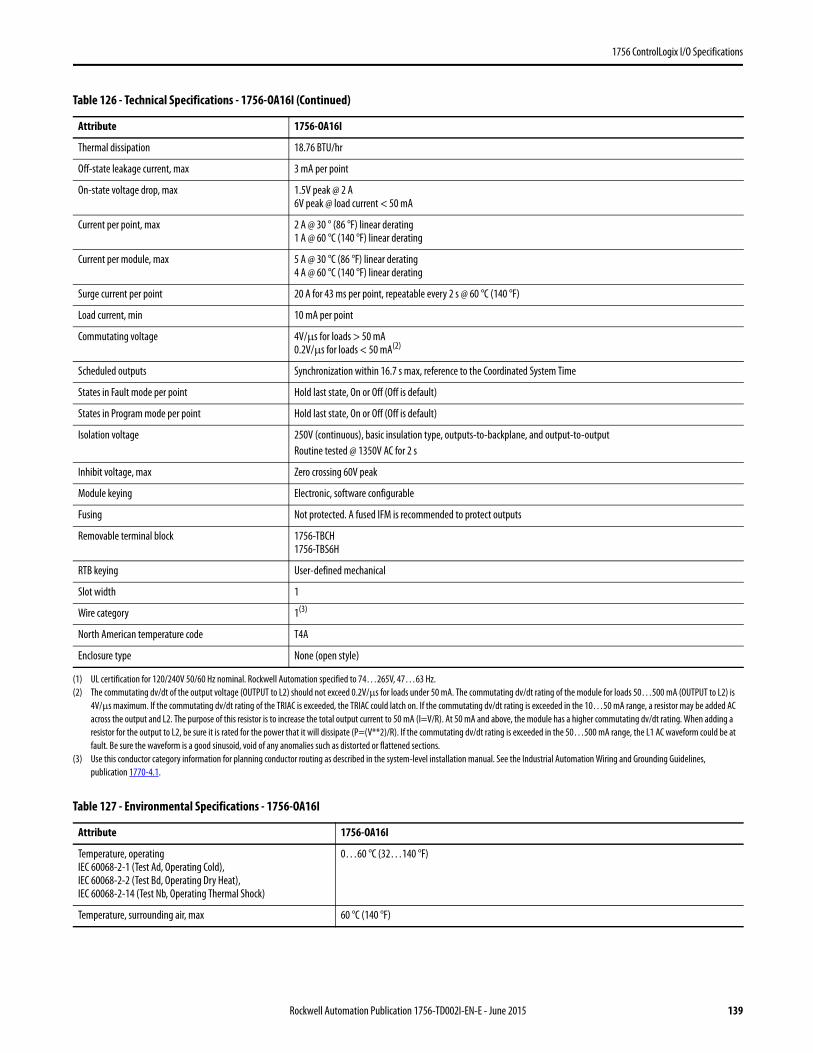
1756 ControlLogix I/O Specifications
Thermal dissipation 18.76 BTU/hr
Off-state leakage current, max 3 mA per point
On-state voltage drop, max 1.5V peak @ 2 A6V peak @ load current < 50 mA
Current per point, max 2 A @ 30 ° (86 °F) linear derating1 A @ 60 °C (140 °F) linear derating
Current per module, max 5 A @ 30 °C (86 °F) linear derating4 A @ 60 °C (140 °F) linear derating
Surge current per point 20 A for 43 ms per point, repeatable every 2 s @ 60 °C (140 °F)
Load current, min 10 mA per point
Commutating voltage 4V/μs for loads > 50 mA0.2V/μs for loads < 50 mA(2)
Scheduled outputs Synchronization within 16.7 s max, reference to the Coordinated System Time
States in Fault mode per point Hold last state, On or Off (Off is default)
States in Program mode per point Hold last state, On or Off (Off is default)
Isolation voltage 250V (continuous), basic insulation type, outputs-to-backplane, and output-to-outputRoutine tested @ 1350V AC for 2 s
Inhibit voltage, max Zero crossing 60V peak
Module keying Electronic, software configurable
Fusing Not protected. A fused IFM is recommended to protect outputs
Removable terminal block 1756-TBCH1756-TBS6H
RTB keying User-defined mechanical
Slot width 1
Wire category 1(3)
North American temperature code T4A
Enclosure type None (open style)
(1) UL certification for 120/240V 50/60 Hz nominal. Rockwell Automation specified to 74…265V, 47…63 Hz.(2) The commutating dv/dt of the output voltage (OUTPUT to L2) should not exceed 0.2V/µs for loads under 50 mA. The commutating dv/dt rating of the module for loads 50…500 mA (OUTPUT to L2) is
4V/µs maximum. If the commutating dv/dt rating of the TRIAC is exceeded, the TRIAC could latch on. If the commutating dv/dt rating is exceeded in the 10…50 mA range, a resistor may be added AC across the output and L2. The purpose of this resistor is to increase the total output current to 50 mA (I=V/R). At 50 mA and above, the module has a higher commutating dv/dt rating. When adding a resistor for the output to L2, be sure it is rated for the power that it will dissipate (P=(V**2)/R). If the commutating dv/dt rating is exceeded in the 50…500 mA range, the L1 AC waveform could be at fault. Be sure the waveform is a good sinusoid, void of any anomalies such as distorted or flattened sections.
(3) Use this conductor category information for planning conductor routing as described in the system-level installation manual. See the Industrial Automation Wiring and Grounding Guidelines, publication 1770-4.1.
Table 127 - Environmental Specifications - 1756-OA16I
Attribute 1756-OA16I
Temperature, operatingIEC 60068-2-1 (Test Ad, Operating Cold),IEC 60068-2-2 (Test Bd, Operating Dry Heat),IEC 60068-2-14 (Test Nb, Operating Thermal Shock)
0…60 °C (32…140 °F)
Temperature, surrounding air, max 60 °C (140 °F)
Table 126 - Technical Specifications - 1756-OA16I (Continued)
Attribute 1756-OA16I
Rockwell Automation Publication 1756-TD002I-EN-E - June 2015 139
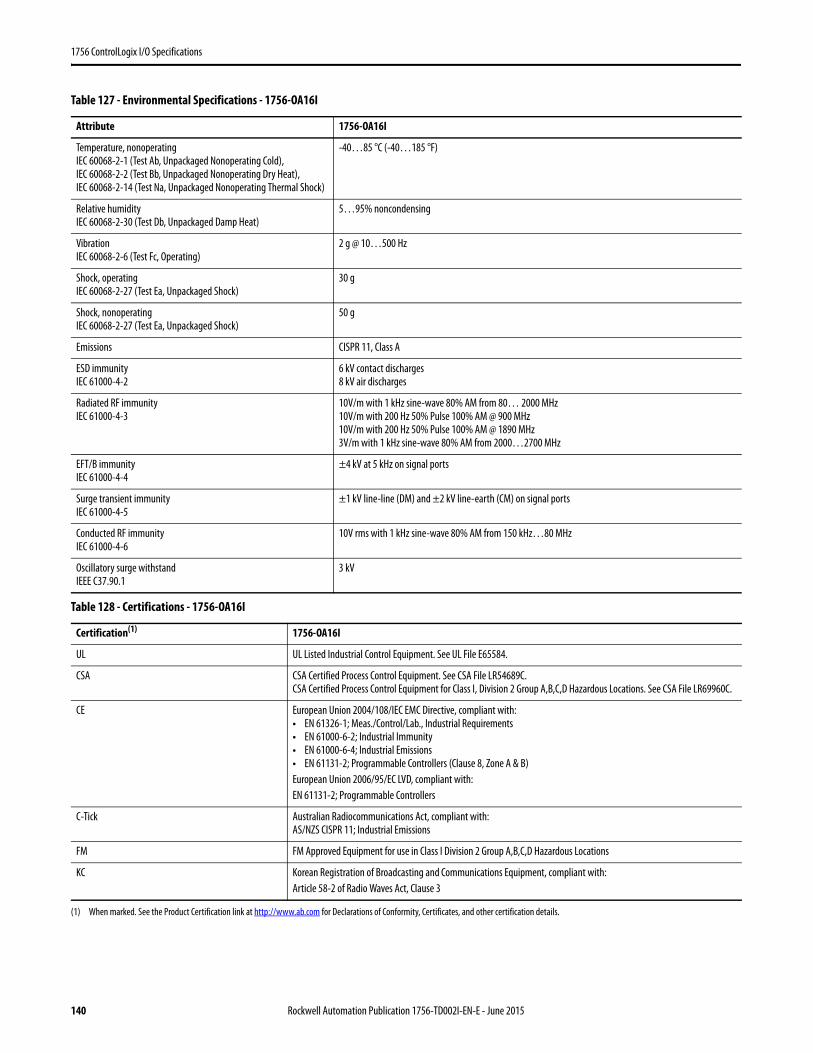
1756 ControlLogix I/O Specifications
Temperature, nonoperatingIEC 60068-2-1 (Test Ab, Unpackaged Nonoperating Cold),IEC 60068-2-2 (Test Bb, Unpackaged Nonoperating Dry Heat),IEC 60068-2-14 (Test Na, Unpackaged Nonoperating Thermal Shock)
-40…85 °C (-40…185 °F)
Relative humidityIEC 60068-2-30 (Test Db, Unpackaged Damp Heat)
5…95% noncondensing
VibrationIEC 60068-2-6 (Test Fc, Operating)
2 g @ 10…500 Hz
Shock, operatingIEC 60068-2-27 (Test Ea, Unpackaged Shock)
30 g
Shock, nonoperatingIEC 60068-2-27 (Test Ea, Unpackaged Shock)
50 g
Emissions CISPR 11, Class A
ESD immunityIEC 61000-4-2
6 kV contact discharges8 kV air discharges
Radiated RF immunityIEC 61000-4-3
10V/m with 1 kHz sine-wave 80% AM from 80… 2000 MHz10V/m with 200 Hz 50% Pulse 100% AM @ 900 MHz10V/m with 200 Hz 50% Pulse 100% AM @ 1890 MHz3V/m with 1 kHz sine-wave 80% AM from 2000…2700 MHz
EFT/B immunityIEC 61000-4-4
±4 kV at 5 kHz on signal ports
Surge transient immunityIEC 61000-4-5
±1 kV line-line (DM) and ±2 kV line-earth (CM) on signal ports
Conducted RF immunityIEC 61000-4-6
10V rms with 1 kHz sine-wave 80% AM from 150 kHz…80 MHz
Oscillatory surge withstandIEEE C37.90.1
3 kV
Table 128 - Certifications - 1756-OA16I
Certification(1)
(1) When marked. See the Product Certification link at http://www.ab.com for Declarations of Conformity, Certificates, and other certification details.
1756-OA16I
UL UL Listed Industrial Control Equipment. See UL File E65584.
CSA CSA Certified Process Control Equipment. See CSA File LR54689C.CSA Certified Process Control Equipment for Class I, Division 2 Group A,B,C,D Hazardous Locations. See CSA File LR69960C.
CE European Union 2004/108/IEC EMC Directive, compliant with:• EN 61326-1; Meas./Control/Lab., Industrial Requirements• EN 61000-6-2; Industrial Immunity• EN 61000-6-4; Industrial Emissions• EN 61131-2; Programmable Controllers (Clause 8, Zone A & B)European Union 2006/95/EC LVD, compliant with:EN 61131-2; Programmable Controllers
C-Tick Australian Radiocommunications Act, compliant with:AS/NZS CISPR 11; Industrial Emissions
FM FM Approved Equipment for use in Class I Division 2 Group A,B,C,D Hazardous Locations
KC Korean Registration of Broadcasting and Communications Equipment, compliant with:Article 58-2 of Radio Waves Act, Clause 3
Table 127 - Environmental Specifications - 1756-OA16I
Attribute 1756-OA16I
140 Rockwell Automation Publication 1756-TD002I-EN-E - June 2015
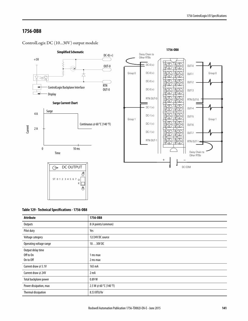
1756 ControlLogix I/O Specifications
1756-OB8
ControlLogix DC (10…30V) output module
Table 129 - Technical Specifications - 1756-OB8
Attribute 1756-OB8
Outputs 8 (4 points/common)
Pilot duty Yes
Voltage category 12/24V DC source
Operating voltage range 10…30V DC
Output delay timeOff to OnOn to Off
1 ms max 2 ms max
Current draw @ 5.1V 165 mA
Current draw @ 24V 2 mA
Total backplane power 0.89 W
Power dissipation, max 2.5 W @ 60 °C (140 °F)
Thermal dissipation 8.53 BTU/hr
12
34
56
78
910
1112
1314
1516
1718
1920
+ –
Group 0Group 0
Group 1Group 1
Daisy Chain to Other RTBs
Daisy Chain to Other RTBs
DC COM
DC-0 (+)
DC-0 (+)
DC-0 (+)
DC-0 (+)
DC-1 (+)
DC-1 (+)
DC-1 (+)
DC-1 (+)
RTN OUT-0
RTN OUT-1
OUT-0
OUT-1
OUT-2
OUT-3
OUT-4
OUT-5
OUT-6
OUT-7
RTN OUT-0
RTN OUT-1
RTNOUT-0
OUT-0
DC-0(+)
ControlLogix Backplane Interface
Display
Continuous @ 60 °C (140 °F)
Surge Current Chart
Simplified Schematic
Surge
+5V
Curre
nt
Time0 10 ms
2 A
4 A
DC OUTPUT
ST 0 1 2 3 4 5 6 7 OK
12
34
56
78
910
1112
1314
1516
1718
1920
+ –
Group 0Group 0
Group 1Group 1
Daisy Chain to Other RTBs
Daisy Chain to Other RTBs
DC COM
DC-0 (+)
DC-0 (+)
DC-0 (+)
DC-0 (+)
DC-1 (+)
DC-1 (+)
DC-1 (+)
DC-1 (+)
RTN OUT-0
RTN OUT-1
OUT-0
OUT-1
OUT-2
OUT-3
OUT-4
OUT-5
OUT-6
OUT-7
RTN OUT-0
RTN OUT-1
1756-OB8
Rockwell Automation Publication 1756-TD002I-EN-E - June 2015 141
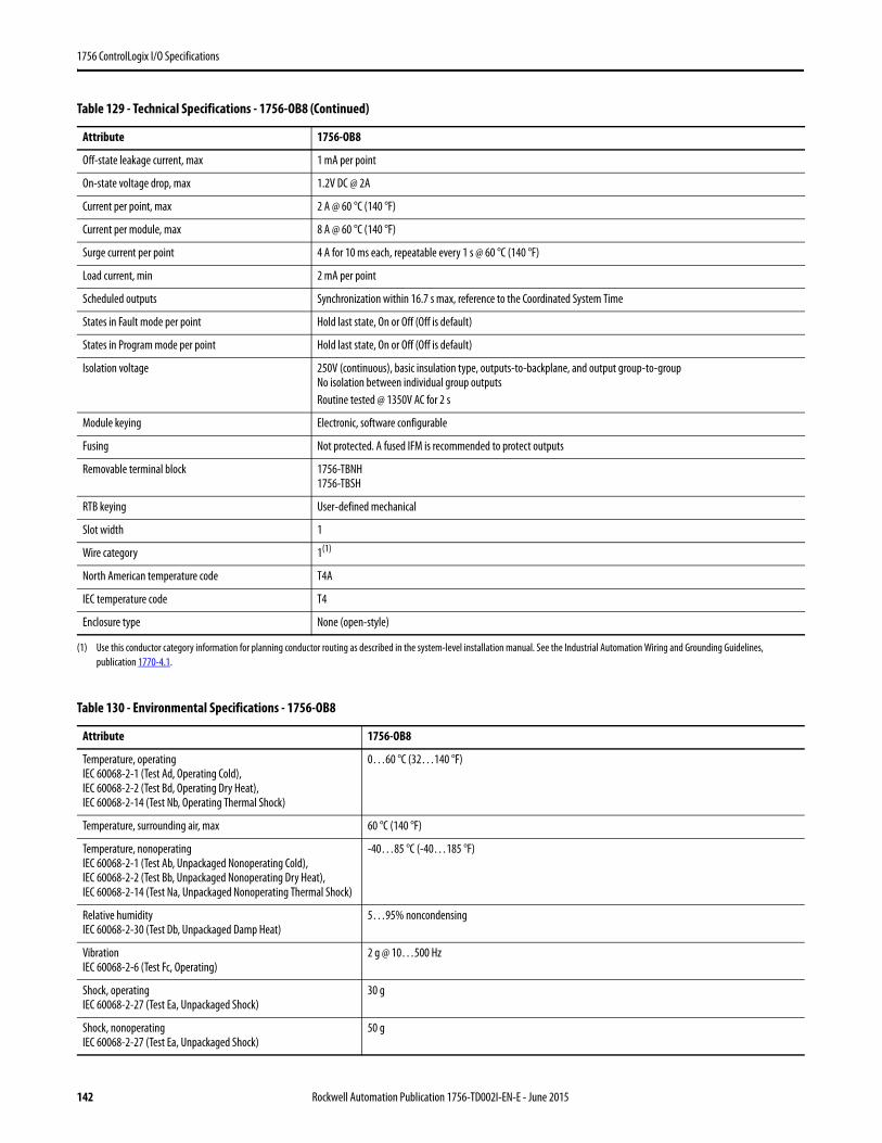
1756 ControlLogix I/O Specifications
Off-state leakage current, max 1 mA per point
On-state voltage drop, max 1.2V DC @ 2A
Current per point, max 2 A @ 60 °C (140 °F)
Current per module, max 8 A @ 60 °C (140 °F)
Surge current per point 4 A for 10 ms each, repeatable every 1 s @ 60 °C (140 °F)
Load current, min 2 mA per point
Scheduled outputs Synchronization within 16.7 s max, reference to the Coordinated System Time
States in Fault mode per point Hold last state, On or Off (Off is default)
States in Program mode per point Hold last state, On or Off (Off is default)
Isolation voltage 250V (continuous), basic insulation type, outputs-to-backplane, and output group-to-groupNo isolation between individual group outputsRoutine tested @ 1350V AC for 2 s
Module keying Electronic, software configurable
Fusing Not protected. A fused IFM is recommended to protect outputs
Removable terminal block 1756-TBNH1756-TBSH
RTB keying User-defined mechanical
Slot width 1
Wire category 1(1)
North American temperature code T4A
IEC temperature code T4
Enclosure type None (open-style)
(1) Use this conductor category information for planning conductor routing as described in the system-level installation manual. See the Industrial Automation Wiring and Grounding Guidelines, publication 1770-4.1.
Table 130 - Environmental Specifications - 1756-OB8
Attribute 1756-OB8
Temperature, operatingIEC 60068-2-1 (Test Ad, Operating Cold),IEC 60068-2-2 (Test Bd, Operating Dry Heat),IEC 60068-2-14 (Test Nb, Operating Thermal Shock)
0…60 °C (32…140 °F)
Temperature, surrounding air, max 60 °C (140 °F)
Temperature, nonoperatingIEC 60068-2-1 (Test Ab, Unpackaged Nonoperating Cold),IEC 60068-2-2 (Test Bb, Unpackaged Nonoperating Dry Heat),IEC 60068-2-14 (Test Na, Unpackaged Nonoperating Thermal Shock)
-40…85 °C (-40…185 °F)
Relative humidityIEC 60068-2-30 (Test Db, Unpackaged Damp Heat)
5…95% noncondensing
VibrationIEC 60068-2-6 (Test Fc, Operating)
2 g @ 10…500 Hz
Shock, operatingIEC 60068-2-27 (Test Ea, Unpackaged Shock)
30 g
Shock, nonoperatingIEC 60068-2-27 (Test Ea, Unpackaged Shock)
50 g
Table 129 - Technical Specifications - 1756-OB8 (Continued)
Attribute 1756-OB8
142 Rockwell Automation Publication 1756-TD002I-EN-E - June 2015
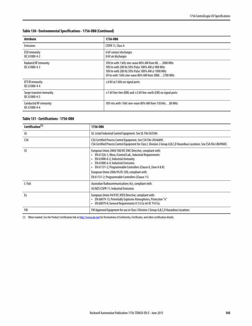
1756 ControlLogix I/O Specifications
Emissions CISPR 11, Class A
ESD immunityIEC 61000-4-2
6 kV contact discharges8 kV air discharges
Radiated RF immunityIEC 61000-4-3
10V/m with 1 kHz sine-wave 80% AM from 80… 2000 MHz10V/m with 200 Hz 50% Pulse 100% AM @ 900 MHz10V/m with 200 Hz 50% Pulse 100% AM @ 1890 MHz3V/m with 1 kHz sine-wave 80% AM from 2000…2700 MHz
EFT/B immunityIEC 61000-4-4
±4 kV at 5 kHz on signal ports
Surge transient immunityIEC 61000-4-5
±1 kV line-line (DM) and ±2 kV line-earth (CM) on signal ports
Conducted RF immunityIEC 61000-4-6
10V rms with 1 kHz sine-wave 80% AM from 150 kHz…80 MHz
Table 131 - Certifications - 1756-OB8
Certification(1)
(1) When marked. See the Product Certification link at http://www.ab.com for Declarations of Conformity, Certificates, and other certification details.
1756-OB8
UL UL Listed Industrial Control Equipment. See UL File E65584.
CSA CSA Certified Process Control Equipment. See CSA File LR54689C.CSA Certified Process Control Equipment for Class I, Division 2 Group A,B,C,D Hazardous Locations. See CSA File LR69960C.
CE European Union 2004/108/IEC EMC Directive, compliant with:• EN 61326-1; Meas./Control/Lab., Industrial Requirements• EN 61000-6-2; Industrial Immunity• EN 61000-6-4; Industrial Emissions• EN 61131-2; Programmable Controllers (Clause 8, Zone A & B)European Union 2006/95/EC LVD, compliant with:EN 61131-2; Programmable Controllers (Clause 11)
C-Tick Australian Radiocommunications Act, compliant with:AS/NZS CISPR 11; Industrial Emissions
Ex European Union 94/9/EC ATEX Directive, compliant with:• EN 60079-15; Potentially Explosive Atmospheres, Protection "n"• EN 60079-0; General Requirements II 3 G Ex nA IIC T4 X Gc
FM FM Approved Equipment for use in Class I Division 2 Group A,B,C,D Hazardous Locations
Table 130 - Environmental Specifications - 1756-OB8 (Continued)
Attribute 1756-OB8
Rockwell Automation Publication 1756-TD002I-EN-E - June 2015 143

1756 ControlLogix I/O Specifications
1756-OB8EI
ControlLogix DC (10…30V) electronically-fused, isolated output module
=
Table 132 - Diagnostic Specifications - 1756-OB8EI
Attribute 1756-OB8EI
Short trip > 4.5 A for 500 μs max (output on, then short)> 4.5 A for 1.5 ms max (output on into short)
Timestamp of diagnostics ±1 ms
Table 133 - Technical Specifications - 1756-OB8EI
Attribute 1756-OB8EI
Outputs 8 individually isolated
Pilot duty Yes
Voltage category 12/24V DC source
Operating voltage range 10…30V DC
01 9
21 11
41 31
61 51
81 71
02 91
22 12
42 32
62 52
82 72
03 92
23 13
43 33
63 53
+
+
-
-
+ –
DC-0 (+)
RTN OUT-0
DC-1 (+)
RTN OUT-1
DC-4 (+)
DC-2 (+)
RTN OUT-2
DC-3 (+)
RTN OUT-3
Not Used
RTN OUT-4DC-5 (+)
RTN OUT-5
DC-6 (+)
RTN OUT-6
DC-7 (+)
RTN OUT-7
Not Used
OUT-0
OUT-0
OUT-1
OUT-1
OUT-4
OUT-2
OUT-2
OUT-3
OUT-3
Not Used
OUT-4OUT-5
OUT-5
OUT-6
OUT-6
OUT-7
OUT-7
Not Used
DC COM
Isolated Wiring
Daisy Chain toOther RTBs
Nonisolated Wiring
Daisy Chain toOther RTBs
8 7
6 5
4 3
2 1
Continuous @ 60 °C (140 °F)
ControlLogix Backplane InterfaceDisplay Output
Device
OUT-0
RTNOUT-0
DC-0(+)
OUT-0
Surge Current Chart
Simplified Schematic
Surge
+5V
Curre
nt
Time0 10 ms
2 A
4 A
DC OUTPUT
ST 0 1 2 3 4 5 6 7 OKFUSE
ELECTRONICALLY FUSED
0 1 2 3 4 5 6 7
1756-OB8EI
144 Rockwell Automation Publication 1756-TD002I-EN-E - June 2015
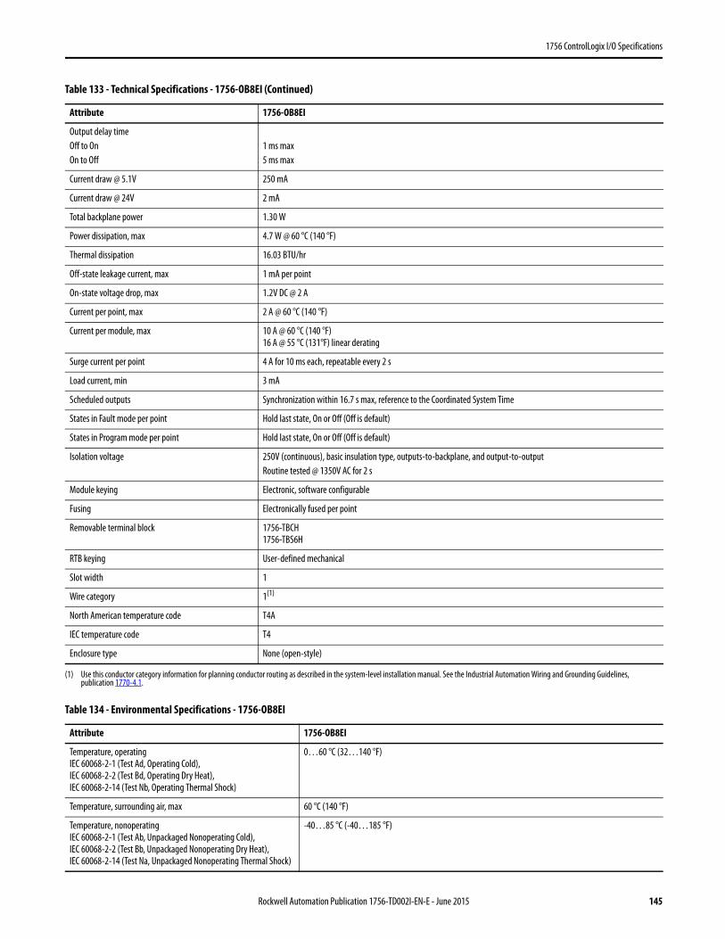
1756 ControlLogix I/O Specifications
Output delay timeOff to OnOn to Off
1 ms max 5 ms max
Current draw @ 5.1V 250 mA
Current draw @ 24V 2 mA
Total backplane power 1.30 W
Power dissipation, max 4.7 W @ 60 °C (140 °F)
Thermal dissipation 16.03 BTU/hr
Off-state leakage current, max 1 mA per point
On-state voltage drop, max 1.2V DC @ 2 A
Current per point, max 2 A @ 60 °C (140 °F)
Current per module, max 10 A @ 60 °C (140 °F)16 A @ 55 °C (131°F) linear derating
Surge current per point 4 A for 10 ms each, repeatable every 2 s
Load current, min 3 mA
Scheduled outputs Synchronization within 16.7 s max, reference to the Coordinated System Time
States in Fault mode per point Hold last state, On or Off (Off is default)
States in Program mode per point Hold last state, On or Off (Off is default)
Isolation voltage 250V (continuous), basic insulation type, outputs-to-backplane, and output-to-outputRoutine tested @ 1350V AC for 2 s
Module keying Electronic, software configurable
Fusing Electronically fused per point
Removable terminal block 1756-TBCH1756-TBS6H
RTB keying User-defined mechanical
Slot width 1
Wire category 1(1)
North American temperature code T4A
IEC temperature code T4
Enclosure type None (open-style)
(1) Use this conductor category information for planning conductor routing as described in the system-level installation manual. See the Industrial Automation Wiring and Grounding Guidelines, publication 1770-4.1.
Table 134 - Environmental Specifications - 1756-OB8EI
Attribute 1756-OB8EI
Temperature, operatingIEC 60068-2-1 (Test Ad, Operating Cold),IEC 60068-2-2 (Test Bd, Operating Dry Heat),IEC 60068-2-14 (Test Nb, Operating Thermal Shock)
0…60 °C (32…140 °F)
Temperature, surrounding air, max 60 °C (140 °F)
Temperature, nonoperatingIEC 60068-2-1 (Test Ab, Unpackaged Nonoperating Cold),IEC 60068-2-2 (Test Bb, Unpackaged Nonoperating Dry Heat),IEC 60068-2-14 (Test Na, Unpackaged Nonoperating Thermal Shock)
-40…85 °C (-40…185 °F)
Table 133 - Technical Specifications - 1756-OB8EI (Continued)
Attribute 1756-OB8EI
Rockwell Automation Publication 1756-TD002I-EN-E - June 2015 145
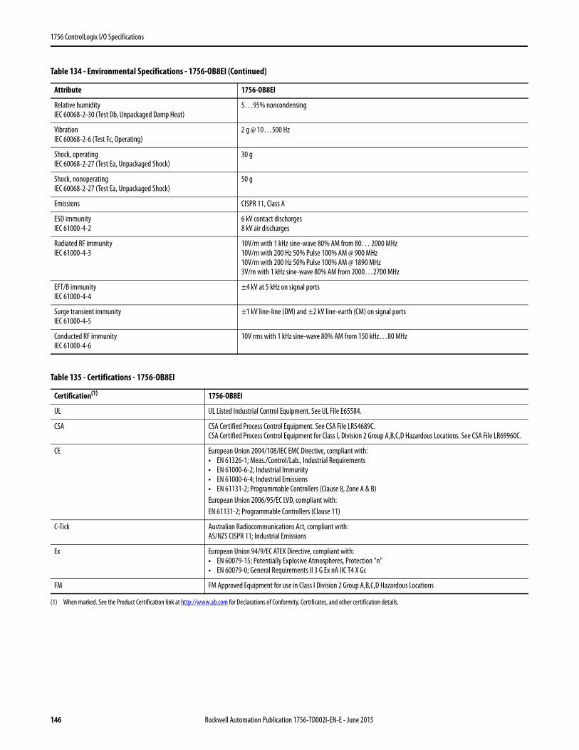
1756 ControlLogix I/O Specifications
Relative humidityIEC 60068-2-30 (Test Db, Unpackaged Damp Heat)
5…95% noncondensing
VibrationIEC 60068-2-6 (Test Fc, Operating)
2 g @ 10…500 Hz
Shock, operatingIEC 60068-2-27 (Test Ea, Unpackaged Shock)
30 g
Shock, nonoperatingIEC 60068-2-27 (Test Ea, Unpackaged Shock)
50 g
Emissions CISPR 11, Class A
ESD immunityIEC 61000-4-2
6 kV contact discharges8 kV air discharges
Radiated RF immunityIEC 61000-4-3
10V/m with 1 kHz sine-wave 80% AM from 80… 2000 MHz10V/m with 200 Hz 50% Pulse 100% AM @ 900 MHz10V/m with 200 Hz 50% Pulse 100% AM @ 1890 MHz3V/m with 1 kHz sine-wave 80% AM from 2000…2700 MHz
EFT/B immunityIEC 61000-4-4
±4 kV at 5 kHz on signal ports
Surge transient immunityIEC 61000-4-5
±1 kV line-line (DM) and ±2 kV line-earth (CM) on signal ports
Conducted RF immunityIEC 61000-4-6
10V rms with 1 kHz sine-wave 80% AM from 150 kHz…80 MHz
Table 135 - Certifications - 1756-OB8EI
Certification(1)
(1) When marked. See the Product Certification link at http://www.ab.com for Declarations of Conformity, Certificates, and other certification details.
1756-OB8EI
UL UL Listed Industrial Control Equipment. See UL File E65584.
CSA CSA Certified Process Control Equipment. See CSA File LR54689C.CSA Certified Process Control Equipment for Class I, Division 2 Group A,B,C,D Hazardous Locations. See CSA File LR69960C.
CE European Union 2004/108/IEC EMC Directive, compliant with:• EN 61326-1; Meas./Control/Lab., Industrial Requirements• EN 61000-6-2; Industrial Immunity• EN 61000-6-4; Industrial Emissions• EN 61131-2; Programmable Controllers (Clause 8, Zone A & B)European Union 2006/95/EC LVD, compliant with:EN 61131-2; Programmable Controllers (Clause 11)
C-Tick Australian Radiocommunications Act, compliant with:AS/NZS CISPR 11; Industrial Emissions
Ex European Union 94/9/EC ATEX Directive, compliant with:• EN 60079-15; Potentially Explosive Atmospheres, Protection "n"• EN 60079-0; General Requirements II 3 G Ex nA IIC T4 X Gc
FM FM Approved Equipment for use in Class I Division 2 Group A,B,C,D Hazardous Locations
Table 134 - Environmental Specifications - 1756-OB8EI (Continued)
Attribute 1756-OB8EI
146 Rockwell Automation Publication 1756-TD002I-EN-E - June 2015
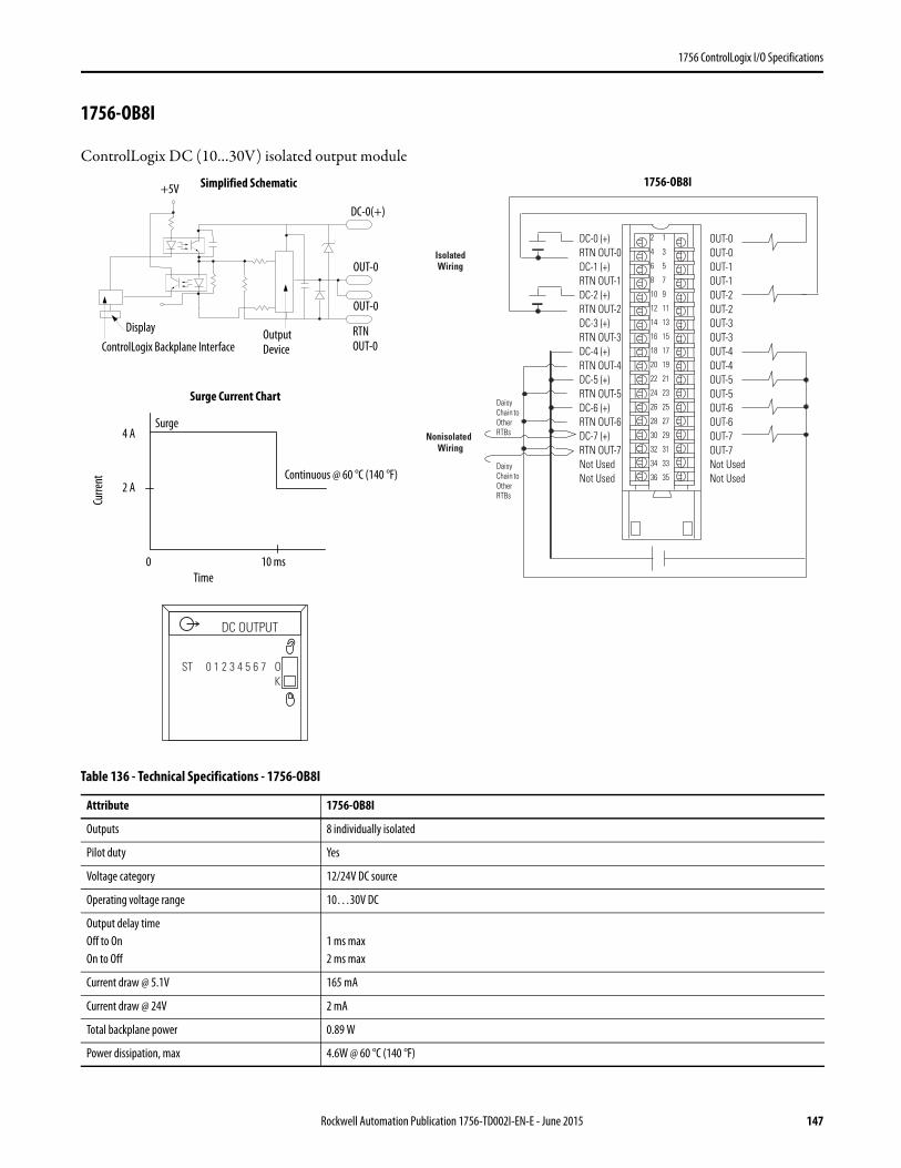
1756 ControlLogix I/O Specifications
1756-OB8I
ControlLogix DC (10…30V) isolated output module
Table 136 - Technical Specifications - 1756-OB8I
Attribute 1756-OB8I
Outputs 8 individually isolated
Pilot duty Yes
Voltage category 12/24V DC source
Operating voltage range 10…30V DC
Output delay timeOff to OnOn to Off
1 ms max 2 ms max
Current draw @ 5.1V 165 mA
Current draw @ 24V 2 mA
Total backplane power 0.89 W
Power dissipation, max 4.6W @ 60 °C (140 °F)
DC-0 (+) RTN OUT-0 DC-1 (+) RTN OUT-1 DC-2 (+) RTN OUT-2 DC-3 (+) RTN OUT-3 DC-4 (+) RTN OUT-4 DC-5 (+) RTN OUT-5 DC-6 (+) RTN OUT-6 DC-7 (+) RTN OUT-7 Not Used Not Used
OUT-0 OUT-0 OUT-1 OUT-1 OUT-2 OUT-2 OUT-3 OUT-3 OUT-4 OUT-4 OUT-5 OUT-5 OUT-6 OUT-6 OUT-7 OUT-7 Not Used Not Used
2
4
6
8
10
12
14
16
18
20
22
24
26
28
30
32
34
36
1
3
5
7
9
11
13
15
17
19
21
23
25
27
29
31
33
35Daisy Chain to Other RTBs
Daisy Chain to Other RTBs
Isolated Wiring
Nonisolated Wiring
Continuous @ 60 °C (140 °F)
ControlLogix Backplane InterfaceDisplay Output
Device
OUT-0
RTNOUT-0
DC-0(+)
OUT-0
Surge Current Chart
Simplified Schematic
Surge
+5V
Curre
nt
Time0 10 ms
2 A
4 A
DC OUTPUT
ST 0 1 2 3 4 5 6 7 OK
1756-OB8I
Rockwell Automation Publication 1756-TD002I-EN-E - June 2015 147

1756 ControlLogix I/O Specifications
Thermal dissipation 15.70 BTU/hr
Off-state leakage current, max 0.5 mA per point
On-state voltage drop, max 0.5V DC @ 2 A
Current per point, max 2 A @ 60 °C (140 °F)
Current per module, max 16 A @ 60 °C (140 °F)
Surge current per point 4 A for 10 ms each, repeatable every 1 s @ 60 °C (140 °F)
Load current, min 2 mA
Scheduled outputs Synchronization within 16.7 s max, reference to the Coordinated System Time
States in Fault mode per point Hold last state, On or Off (Off is default)
States in Program mode per point Hold last state, On or Off (Off is default)
Isolation voltage 250V (continuous), reinforced insulation type, outputs-to-backplane250V (continuous), basic insulation type, output-to-outputRoutine tested @ 1350V AC for 2 s
Module keying Electronic, software configurable
Fusing Not protected. A fused IFM is recommended to protect outputs
Removable terminal block 1756-TBCH1756-TBS6H
RTB keying User-defined mechanical
Slot width 1
Wire category 1(1)
North American temperature code T4A
Enclosure type None (open-style)
(1) Use this conductor category information for planning conductor routing as described in the system-level installation manual. See the Industrial Automation Wiring and Grounding Guidelines, publication 1770-4.1.
Table 137 - Environmental Specifications - 1756-OB8I
Attribute 1756-OB8I
Temperature, operatingIEC 60068-2-1 (Test Ad, Operating Cold),IEC 60068-2-2 (Test Bd, Operating Dry Heat),IEC 60068-2-14 (Test Nb, Operating Thermal Shock)
0…60 °C (32…140 °F)
Temperature, surrounding air, max 60 °C (140 °F)
Temperature, nonoperatingIEC 60068-2-1 (Test Ab, Unpackaged Nonoperating Cold),IEC 60068-2-2 (Test Bb, Unpackaged Nonoperating Dry Heat),IEC 60068-2-14 (Test Na, Unpackaged Nonoperating Thermal Shock)
-40…85 °C (-40…185 °F)
Relative humidityIEC 60068-2-30 (Test Db, Unpackaged Damp Heat)
5…95% noncondensing
VibrationIEC 60068-2-6 (Test Fc, Operating)
2 g @ 10…500 Hz
Shock, operatingIEC 60068-2-27 (Test Ea, Unpackaged Shock)
30 g
Shock, nonoperatingIEC 60068-2-27 (Test Ea, Unpackaged Shock)
50 g
Table 136 - Technical Specifications - 1756-OB8I (Continued)
Attribute 1756-OB8I
148 Rockwell Automation Publication 1756-TD002I-EN-E - June 2015
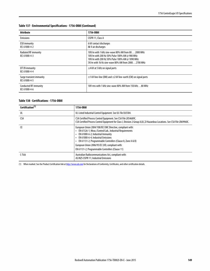
1756 ControlLogix I/O Specifications
Emissions CISPR 11, Class A
ESD immunityIEC 61000-4-2
6 kV contact discharges8k V air discharges
Radiated RF immunityIEC 61000-4-3
10V/m with 1 kHz sine-wave 80% AM from 80… 2000 MHz10V/m with 200 Hz 50% Pulse 100% AM @ 900 MHz10V/m with 200 Hz 50% Pulse 100% AM @ 1890 MHz3V/m with 1k Hz sine-wave 80% AM from 2000…2700 MHz
EFT/B immunityIEC 61000-4-4
±4 kV at 5 kHz on signal ports
Surge transient immunityIEC 61000-4-5
±1 kV line-line (DM) and ±2 kV line-earth (CM) on signal ports
Conducted RF immunityIEC 61000-4-6
10V rms with 1 kHz sine-wave 80% AM from 150 kHz…80 MHz
Table 138 - Certifications - 1756-OB8I
Certification(1)
(1) When marked. See the Product Certification link at http://www.ab.com for Declarations of Conformity, Certificates, and other certification details.
1756-OB8I
UL UL Listed Industrial Control Equipment. See UL File E65584.
CSA CSA Certified Process Control Equipment. See CSA File LR54689C.CSA Certified Process Control Equipment for Class I, Division 2 Group A,B,C,D Hazardous Locations. See CSA File LR69960C.
CE European Union 2004/108/IEC EMC Directive, compliant with:• EN 61326-1; Meas./Control/Lab., Industrial Requirements• EN 61000-6-2; Industrial Immunity• EN 61000-6-4; Industrial Emissions• EN 61131-2; Programmable Controllers (Clause 8, Zone A & B)European Union 2006/95/EC LVD, compliant with:EN 61131-2; Programmable Controllers (Clause 11)
C-Tick Australian Radiocommunications Act, compliant with:AS/NZS CISPR 11; Industrial Emissions
Table 137 - Environmental Specifications - 1756-OB8I (Continued)
Attribute 1756-OB8I
Rockwell Automation Publication 1756-TD002I-EN-E - June 2015 149
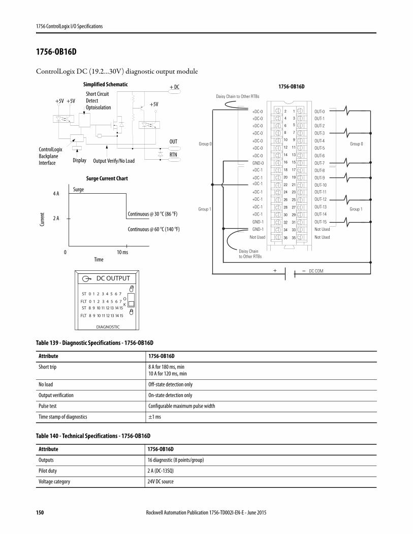
1756 ControlLogix I/O Specifications
1756-OB16D
ControlLogix DC (19.2…30V) diagnostic output module
Table 139 - Diagnostic Specifications - 1756-OB16D
Attribute 1756-OB16D
Short trip 8 A for 180 ms, min10 A for 120 ms, min
No load Off-state detection only
Output verification On-state detection only
Pulse test Configurable maximum pulse width
Time stamp of diagnostics ±1 ms
Table 140 - Technical Specifications - 1756-OB16D
Attribute 1756-OB16D
Outputs 16 diagnostic (8 points/group)
Pilot duty 2 A (DC-13SQ)
Voltage category 24V DC source
12
34
56
78
910
1112
1314
1516
1718
1920
2122
2324
2526
2728
2930
3132
3334
3536
+ –
Daisy Chain to Other RTBs
DC COM
0 puorG0 puorG
1 puorG1 puorG
+DC-0
+DC-0
+DC-0
+DC-0
+DC-1
+DC-0
+DC-0
+DC-0
GND-0
Not Used
+DC-1+DC-1
+DC-1
+DC-1
+DC-1
+DC-1
GND-1
GND-1
OUT-0
OUT-1
OUT-2
OUT-3
OUT-8
OUT-4
OUT-5
OUT-6
OUT-7
Not Used
OUT-9
OUT-10
OUT-11
OUT-12
OUT-13
OUT-14
OUT-15
Not Used
Daisy Chain to Other RTBs
ControlLogix Backplane Interface Display
+5VShort Circuit Detect Optoisolation
+5V
+ DC
OUT
RTNOutput Verify/No Load
Surge Current Chart
Continuous @ 30 °C (86 °F)
Simplified Schematic
Continuous @ 60 °C (140 °F)
Surge
+5V
Curre
nt
Time0 10 ms
2 A
4 A
ST 0 1 2 3 4 5 6 7
FLT 0 1 2 3 4 5 6 7
DIAGNOSTIC
ST 8 9 10 11 12 13 14 15
FLT 8 9 10 11 12 13 14 15
DC OUTPUT
OK
1756-OB16D
150 Rockwell Automation Publication 1756-TD002I-EN-E - June 2015
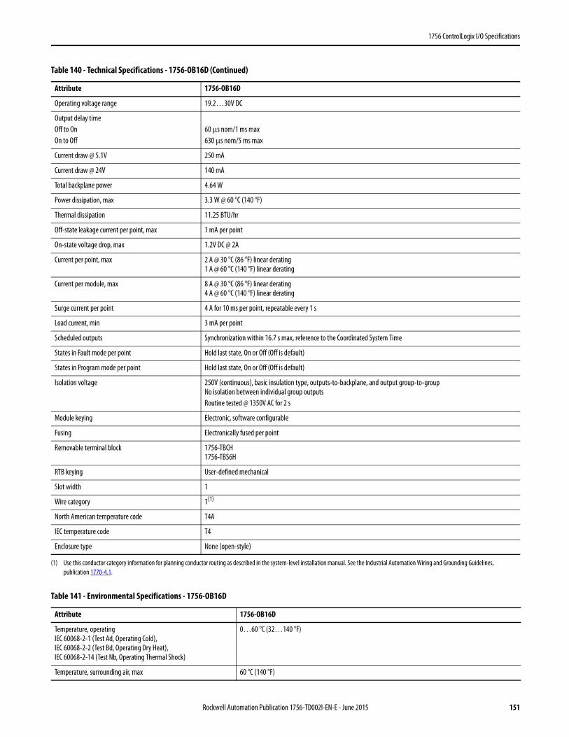
1756 ControlLogix I/O Specifications
Operating voltage range 19.2…30V DC
Output delay timeOff to OnOn to Off
60 μs nom/1 ms max 630 μs nom/5 ms max
Current draw @ 5.1V 250 mA
Current draw @ 24V 140 mA
Total backplane power 4.64 W
Power dissipation, max 3.3 W @ 60 °C (140 °F)
Thermal dissipation 11.25 BTU/hr
Off-state leakage current per point, max 1 mA per point
On-state voltage drop, max 1.2V DC @ 2A
Current per point, max 2 A @ 30 °C (86 °F) linear derating1 A @ 60 °C (140 °F) linear derating
Current per module, max 8 A @ 30 °C (86 °F) linear derating4 A @ 60 °C (140 °F) linear derating
Surge current per point 4 A for 10 ms per point, repeatable every 1 s
Load current, min 3 mA per point
Scheduled outputs Synchronization within 16.7 s max, reference to the Coordinated System Time
States in Fault mode per point Hold last state, On or Off (Off is default)
States in Program mode per point Hold last state, On or Off (Off is default)
Isolation voltage 250V (continuous), basic insulation type, outputs-to-backplane, and output group-to-groupNo isolation between individual group outputsRoutine tested @ 1350V AC for 2 s
Module keying Electronic, software configurable
Fusing Electronically fused per point
Removable terminal block 1756-TBCH1756-TBS6H
RTB keying User-defined mechanical
Slot width 1
Wire category 1(1)
North American temperature code T4A
IEC temperature code T4
Enclosure type None (open-style)
(1) Use this conductor category information for planning conductor routing as described in the system-level installation manual. See the Industrial Automation Wiring and Grounding Guidelines, publication 1770-4.1.
Table 141 - Environmental Specifications - 1756-OB16D
Attribute 1756-OB16D
Temperature, operatingIEC 60068-2-1 (Test Ad, Operating Cold),IEC 60068-2-2 (Test Bd, Operating Dry Heat),IEC 60068-2-14 (Test Nb, Operating Thermal Shock)
0…60 °C (32…140 °F)
Temperature, surrounding air, max 60 °C (140 °F)
Table 140 - Technical Specifications - 1756-OB16D (Continued)
Attribute 1756-OB16D
Rockwell Automation Publication 1756-TD002I-EN-E - June 2015 151
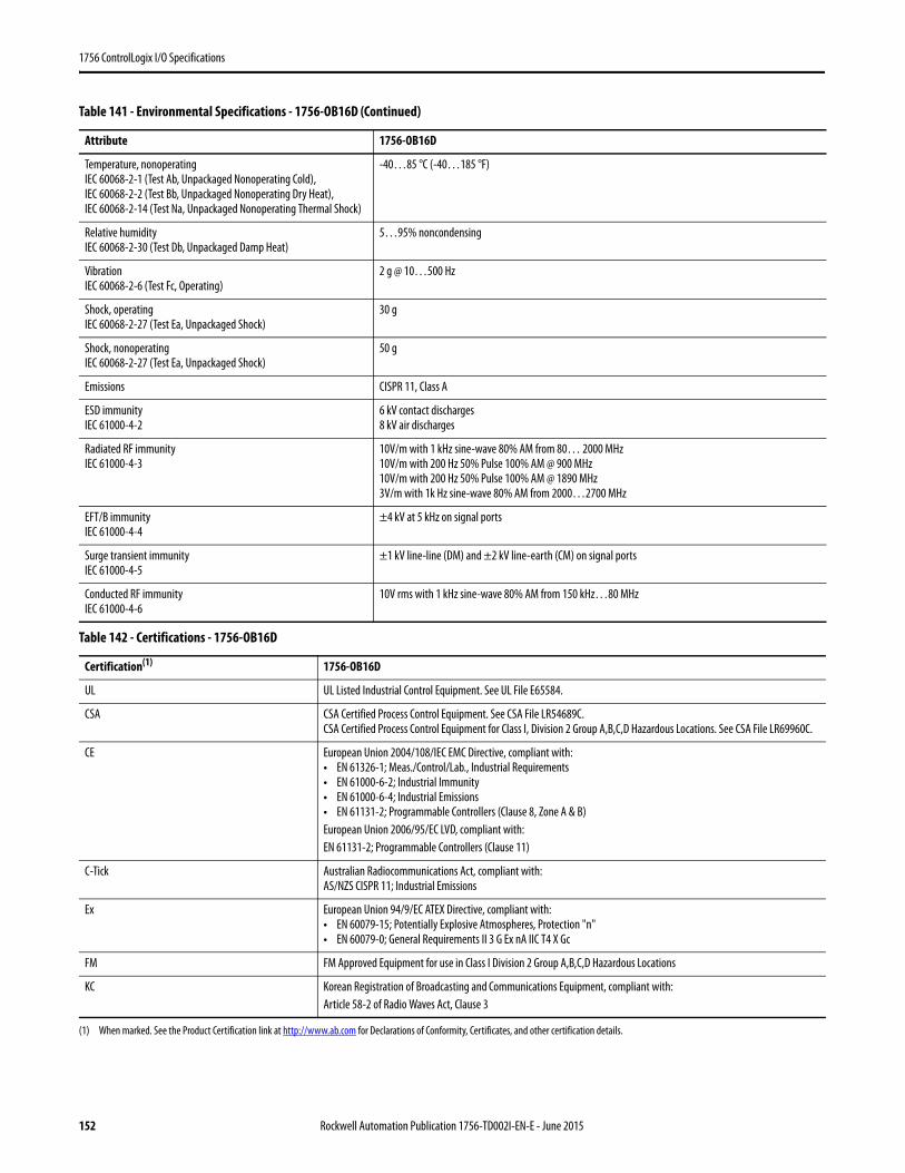
1756 ControlLogix I/O Specifications
Temperature, nonoperatingIEC 60068-2-1 (Test Ab, Unpackaged Nonoperating Cold),IEC 60068-2-2 (Test Bb, Unpackaged Nonoperating Dry Heat),IEC 60068-2-14 (Test Na, Unpackaged Nonoperating Thermal Shock)
-40…85 °C (-40…185 °F)
Relative humidityIEC 60068-2-30 (Test Db, Unpackaged Damp Heat)
5…95% noncondensing
VibrationIEC 60068-2-6 (Test Fc, Operating)
2 g @ 10…500 Hz
Shock, operatingIEC 60068-2-27 (Test Ea, Unpackaged Shock)
30 g
Shock, nonoperatingIEC 60068-2-27 (Test Ea, Unpackaged Shock)
50 g
Emissions CISPR 11, Class A
ESD immunityIEC 61000-4-2
6 kV contact discharges8 kV air discharges
Radiated RF immunityIEC 61000-4-3
10V/m with 1 kHz sine-wave 80% AM from 80… 2000 MHz10V/m with 200 Hz 50% Pulse 100% AM @ 900 MHz10V/m with 200 Hz 50% Pulse 100% AM @ 1890 MHz3V/m with 1k Hz sine-wave 80% AM from 2000…2700 MHz
EFT/B immunityIEC 61000-4-4
±4 kV at 5 kHz on signal ports
Surge transient immunityIEC 61000-4-5
±1 kV line-line (DM) and ±2 kV line-earth (CM) on signal ports
Conducted RF immunityIEC 61000-4-6
10V rms with 1 kHz sine-wave 80% AM from 150 kHz…80 MHz
Table 142 - Certifications - 1756-OB16D
Certification(1)
(1) When marked. See the Product Certification link at http://www.ab.com for Declarations of Conformity, Certificates, and other certification details.
1756-OB16D
UL UL Listed Industrial Control Equipment. See UL File E65584.
CSA CSA Certified Process Control Equipment. See CSA File LR54689C.CSA Certified Process Control Equipment for Class I, Division 2 Group A,B,C,D Hazardous Locations. See CSA File LR69960C.
CE European Union 2004/108/IEC EMC Directive, compliant with:• EN 61326-1; Meas./Control/Lab., Industrial Requirements• EN 61000-6-2; Industrial Immunity• EN 61000-6-4; Industrial Emissions• EN 61131-2; Programmable Controllers (Clause 8, Zone A & B)European Union 2006/95/EC LVD, compliant with:EN 61131-2; Programmable Controllers (Clause 11)
C-Tick Australian Radiocommunications Act, compliant with:AS/NZS CISPR 11; Industrial Emissions
Ex European Union 94/9/EC ATEX Directive, compliant with:• EN 60079-15; Potentially Explosive Atmospheres, Protection "n"• EN 60079-0; General Requirements II 3 G Ex nA IIC T4 X Gc
FM FM Approved Equipment for use in Class I Division 2 Group A,B,C,D Hazardous Locations
KC Korean Registration of Broadcasting and Communications Equipment, compliant with:Article 58-2 of Radio Waves Act, Clause 3
Table 141 - Environmental Specifications - 1756-OB16D (Continued)
Attribute 1756-OB16D
152 Rockwell Automation Publication 1756-TD002I-EN-E - June 2015
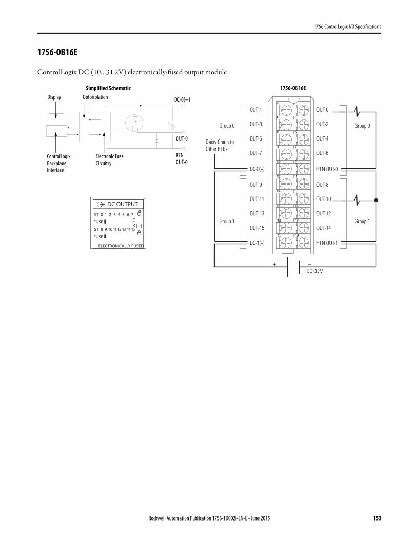
1756 ControlLogix I/O Specifications
1756-OB16E
ControlLogix DC (10…31.2V) electronically-fused output module
12
34
56
78
910
1112
1314
1516
1718
1920
+ –
Daisy Chain to Other RTBs
Group 0Group 0
Group 1Group 1
DC COM
OUT-1
OUT-3
OUT-5
OUT-7
OUT-9
OUT-11
OUT-13
OUT-15
DC-0(+)
DC-1(+)
OUT-0
OUT-2
OUT-4
OUT-6
OUT-8
OUT-10
OUT-12
OUT-14
RTN OUT-0
RTN OUT-1
ControlLogix Backplane Interface
Electronic Fuse Circuitry
Display Optoisolation
RTNOUT-0
OUT-0
DC-0(+)
Simplified Schematic
DC OUTPUT
ST 0 1 2 3 4 5 6 7
ST 8 9 10 11 12 13 14 15
OK
FUSE
FUSE
ELECTRONICALLY FUSED
1756-OB16E
Rockwell Automation Publication 1756-TD002I-EN-E - June 2015 153

1756 ControlLogix I/O Specifications
Table 143 - Technical Specifications - 1756-OB16E
Attribute 1756-OB16E
Outputs 16 electronically fused (8 points/group)
Voltage category 12/24V DC source
Operating voltage range 10…31.2V DC
Output delay timeOff to OnOn to Off
70 μs nom/1 ms max360 μs nom/1 ms max
Current draw @ 5.1V 250 mA
Current draw @ 24V 2 mA
Total backplane power 1.32 W
Power dissipation, max 4.1 W @ 60 °C (140 °F)
Surge Current Charts
154 Rockwell Automation Publication 1756-TD002I-EN-E - June 2015
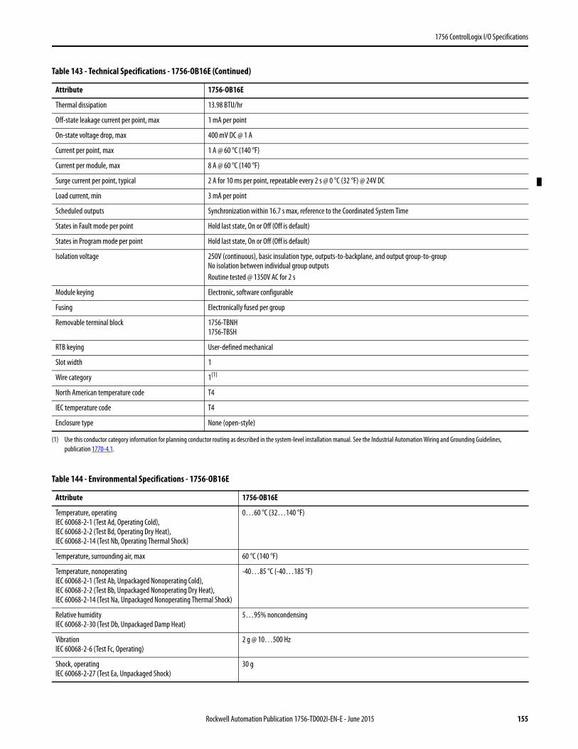
1756 ControlLogix I/O Specifications
Thermal dissipation 13.98 BTU/hr
Off-state leakage current per point, max 1 mA per point
On-state voltage drop, max 400 mV DC @ 1 A
Current per point, max 1 A @ 60 °C (140 °F)
Current per module, max 8 A @ 60 °C (140 °F)
Surge current per point, typical 2 A for 10 ms per point, repeatable every 2 s @ 0 °C (32 °F) @ 24V DC
Load current, min 3 mA per point
Scheduled outputs Synchronization within 16.7 s max, reference to the Coordinated System Time
States in Fault mode per point Hold last state, On or Off (Off is default)
States in Program mode per point Hold last state, On or Off (Off is default)
Isolation voltage 250V (continuous), basic insulation type, outputs-to-backplane, and output group-to-groupNo isolation between individual group outputsRoutine tested @ 1350V AC for 2 s
Module keying Electronic, software configurable
Fusing Electronically fused per group
Removable terminal block 1756-TBNH1756-TBSH
RTB keying User-defined mechanical
Slot width 1
Wire category 1(1)
North American temperature code T4
IEC temperature code T4
Enclosure type None (open-style)
(1) Use this conductor category information for planning conductor routing as described in the system-level installation manual. See the Industrial Automation Wiring and Grounding Guidelines, publication 1770-4.1.
Table 144 - Environmental Specifications - 1756-OB16E
Attribute 1756-OB16E
Temperature, operatingIEC 60068-2-1 (Test Ad, Operating Cold),IEC 60068-2-2 (Test Bd, Operating Dry Heat),IEC 60068-2-14 (Test Nb, Operating Thermal Shock)
0…60 °C (32…140 °F)
Temperature, surrounding air, max 60 °C (140 °F)
Temperature, nonoperatingIEC 60068-2-1 (Test Ab, Unpackaged Nonoperating Cold),IEC 60068-2-2 (Test Bb, Unpackaged Nonoperating Dry Heat),IEC 60068-2-14 (Test Na, Unpackaged Nonoperating Thermal Shock)
-40…85 °C (-40…185 °F)
Relative humidityIEC 60068-2-30 (Test Db, Unpackaged Damp Heat)
5…95% noncondensing
VibrationIEC 60068-2-6 (Test Fc, Operating)
2 g @ 10…500 Hz
Shock, operatingIEC 60068-2-27 (Test Ea, Unpackaged Shock)
30 g
Table 143 - Technical Specifications - 1756-OB16E (Continued)
Attribute 1756-OB16E
Rockwell Automation Publication 1756-TD002I-EN-E - June 2015 155
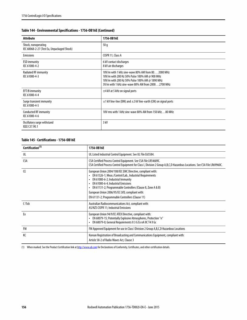
1756 ControlLogix I/O Specifications
Shock, nonoperatingIEC 60068-2-27 (Test Ea, Unpackaged Shock)
50 g
Emissions CISPR 11, Class A
ESD immunityIEC 61000-4-2
6 kV contact discharges8 kV air discharges
Radiated RF immunityIEC 61000-4-3
10V/m with 1 kHz sine-wave 80% AM from 80… 2000 MHz10V/m with 200 Hz 50% Pulse 100% AM @ 900 MHz10V/m with 200 Hz 50% Pulse 100% AM @ 1890 MHz3V/m with 1 kHz sine-wave 80% AM from 2000…2700 MHz
EFT/B immunityIEC 61000-4-4
±4 kV at 5 kHz on signal ports
Surge transient immunityIEC 61000-4-5
±1 kV line-line (DM) and ±2 kV line-earth (CM) on signal ports
Conducted RF immunityIEC 61000-4-6
10V rms with 1 kHz sine-wave 80% AM from 150 kHz…80 MHz
Oscillatory surge withstandIEEE C37.90.1
3 kV
Table 145 - Certifications - 1756-OB16E
Certification(1)
(1) When marked. See the Product Certification link at http://www.ab.com for Declarations of Conformity, Certificates, and other certification details.
1756-OB16E
UL UL Listed Industrial Control Equipment. See UL File E65584.
CSA CSA Certified Process Control Equipment. See CSA File LR54689C.CSA Certified Process Control Equipment for Class I, Division 2 Group A,B,C,D Hazardous Locations. See CSA File LR69960C.
CE European Union 2004/108/IEC EMC Directive, compliant with:• EN 61326-1; Meas./Control/Lab., Industrial Requirements• EN 61000-6-2; Industrial Immunity• EN 61000-6-4; Industrial Emissions• EN 61131-2; Programmable Controllers (Clause 8, Zone A & B)European Union 2006/95/EC LVD, compliant with:EN 61131-2; Programmable Controllers (Clause 11)
C-Tick Australian Radiocommunications Act, compliant with:AS/NZS CISPR 11; Industrial Emissions
Ex European Union 94/9/EC ATEX Directive, compliant with:• EN 60079-15; Potentially Explosive Atmospheres, Protection "n"• EN 60079-0; General Requirements II 3 G Ex nA IIC T4 X Gc
FM FM Approved Equipment for use in Class I Division 2 Group A,B,C,D Hazardous Locations
KC Korean Registration of Broadcasting and Communications Equipment, compliant with:Article 58-2 of Radio Waves Act, Clause 3
Table 144 - Environmental Specifications - 1756-OB16E (Continued)
Attribute 1756-OB16E
156 Rockwell Automation Publication 1756-TD002I-EN-E - June 2015
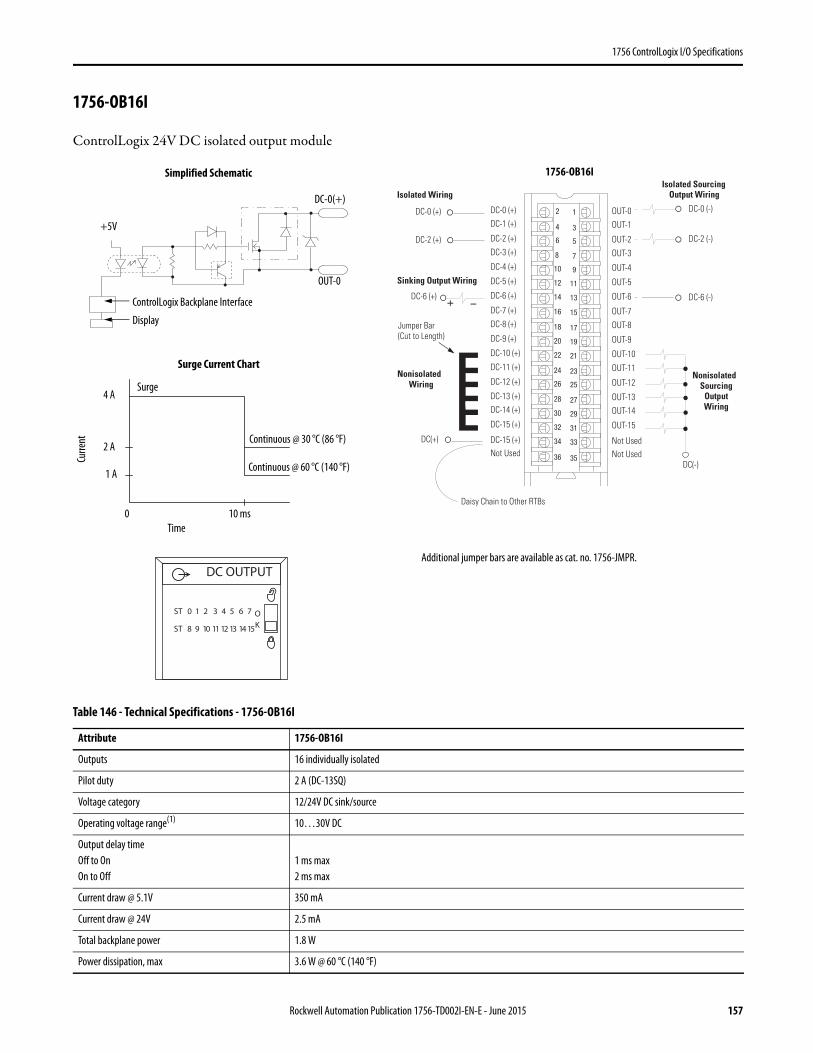
1756 ControlLogix I/O Specifications
1756-OB16I
ControlLogix 24V DC isolated output module
Table 146 - Technical Specifications - 1756-OB16I
Attribute 1756-OB16I
Outputs 16 individually isolated
Pilot duty 2 A (DC-13SQ)
Voltage category 12/24V DC sink/source
Operating voltage range(1) 10…30V DC
Output delay timeOff to OnOn to Off
1 ms max 2 ms max
Current draw @ 5.1V 350 mA
Current draw @ 24V 2.5 mA
Total backplane power 1.8 W
Power dissipation, max 3.6 W @ 60 °C (140 °F)
12
34
56
78
910
1112
1314
1516
1718
1920
2122
2324
2526
2728
2930
3132
3334
3536
+ –
Nonisolated Wiring
Isolated Wiring
Daisy Chain to Other RTBs
DC-0 (+)DC-1 (+)
DC-2 (+)
DC-3 (+)
DC-8 (+)
DC-4 (+)
DC-5 (+)
DC-6 (+)
DC-7 (+)
Not Used
DC-9 (+)
DC-10 (+)
DC-11 (+)
DC-12 (+)
DC-13 (+)DC-14 (+)
DC-15 (+)
DC-15 (+)
OUT-0OUT-1
OUT-2
OUT-3
OUT-8
OUT-4
OUT-5
OUT-6
OUT-7
Not Used
OUT-9
OUT-10
OUT-11
OUT-12
OUT-13OUT-14
OUT-15
Not Used
DC-0 (+)
DC(+)
Jumper Bar (Cut to Length)
DC-2 (+)
DC-6 (+)
Sinking Output Wiring
Nonisolated Sourcing
Output Wiring
Isolated Sourcing Output Wiring
DC-0 (-)
DC-2 (-)
DC-6 (-)
DC(-)
ControlLogix Backplane Interface
Continuous @ 60 °C (140 °F)
Display
Surge Current Chart
Simplified Schematic
Surge
Continuous @ 30 °C (86 °F)
OUT-0
DC-0(+)
Curre
nt
Time0 10 ms
2 A
4 A
+5V
Additional jumper bars are available as cat. no. 1756-JMPR.DC OUTPUT
ST 0 1 2 3 4 5 6 7
ST 8 9 10 11 12 13 14 15
OK
1 A
1756-OB16I
Rockwell Automation Publication 1756-TD002I-EN-E - June 2015 157
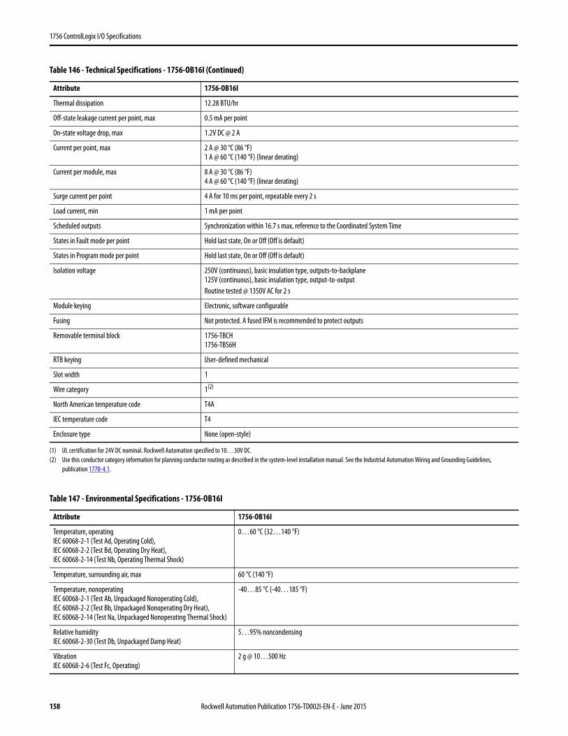
1756 ControlLogix I/O Specifications
Thermal dissipation 12.28 BTU/hr
Off-state leakage current per point, max 0.5 mA per point
On-state voltage drop, max 1.2V DC @ 2 A
Current per point, max 2 A @ 30 °C (86 °F)1 A @ 60 °C (140 °F) (linear derating)
Current per module, max 8 A @ 30 °C (86 °F)4 A @ 60 °C (140 °F) (linear derating)
Surge current per point 4 A for 10 ms per point, repeatable every 2 s
Load current, min 1 mA per point
Scheduled outputs Synchronization within 16.7 s max, reference to the Coordinated System Time
States in Fault mode per point Hold last state, On or Off (Off is default)
States in Program mode per point Hold last state, On or Off (Off is default)
Isolation voltage 250V (continuous), basic insulation type, outputs-to-backplane125V (continuous), basic insulation type, output-to-outputRoutine tested @ 1350V AC for 2 s
Module keying Electronic, software configurable
Fusing Not protected. A fused IFM is recommended to protect outputs
Removable terminal block 1756-TBCH1756-TBS6H
RTB keying User-defined mechanical
Slot width 1
Wire category 1(2)
North American temperature code T4A
IEC temperature code T4
Enclosure type None (open-style)
(1) UL certification for 24V DC nominal. Rockwell Automation specified to 10…30V DC.(2) Use this conductor category information for planning conductor routing as described in the system-level installation manual. See the Industrial Automation Wiring and Grounding Guidelines,
publication 1770-4.1.
Table 147 - Environmental Specifications - 1756-OB16I
Attribute 1756-OB16I
Temperature, operatingIEC 60068-2-1 (Test Ad, Operating Cold),IEC 60068-2-2 (Test Bd, Operating Dry Heat),IEC 60068-2-14 (Test Nb, Operating Thermal Shock)
0…60 °C (32…140 °F)
Temperature, surrounding air, max 60 °C (140 °F)
Temperature, nonoperatingIEC 60068-2-1 (Test Ab, Unpackaged Nonoperating Cold),IEC 60068-2-2 (Test Bb, Unpackaged Nonoperating Dry Heat),IEC 60068-2-14 (Test Na, Unpackaged Nonoperating Thermal Shock)
-40…85 °C (-40…185 °F)
Relative humidityIEC 60068-2-30 (Test Db, Unpackaged Damp Heat)
5…95% noncondensing
VibrationIEC 60068-2-6 (Test Fc, Operating)
2 g @ 10…500 Hz
Table 146 - Technical Specifications - 1756-OB16I (Continued)
Attribute 1756-OB16I
158 Rockwell Automation Publication 1756-TD002I-EN-E - June 2015

1756 ControlLogix I/O Specifications
Shock, operatingIEC 60068-2-27 (Test Ea, Unpackaged Shock)
30 g
Shock, nonoperatingIEC 60068-2-27 (Test Ea, Unpackaged Shock)
50 g
Emissions CISPR 11, Class A
ESD immunityIEC 61000-4-2
6 kV contact discharges8 kV air discharges
Radiated RF immunityIEC 61000-4-3
10V/m with 1 kHz sine-wave 80% AM from 80… 2000 MHz10V/m with 200 Hz 50% Pulse 100% AM @ 900 MHz10V/m with 200 Hz 50% Pulse 100% AM @ 1890 MHz3V/m with 1 kHz sine-wave 80% AM from 2000…2700 MHz
EFT/B immunityIEC 61000-4-4
±4 kV at 5 kHz on signal ports
Surge transient immunityIEC 61000-4-5
±1 kV line-line (DM) and ±2 kV line-earth (CM) on signal ports
Conducted RF immunityIEC 61000-4-6
10V rms with 1 kHz sine-wave 80% AM from 150 kHz…80 MHz
Table 148 - Certifications - 1756-OB16I
Certification(1)
(1) When marked. See the Product Certification link at http://www.ab.com for Declarations of Conformity, Certificates, and other certification details.
1756-OB16I
UL UL Listed Industrial Control Equipment. See UL File E65584.
CSA CSA Certified Process Control Equipment. See CSA File LR54689C.CSA Certified Process Control Equipment for Class I, Division 2 Group A,B,C,D Hazardous Locations. See CSA File LR69960C.
CE European Union 2004/108/IEC EMC Directive, compliant with:• EN 61326-1; Meas./Control/Lab., Industrial Requirements• EN 61000-6-2; Industrial Immunity• EN 61000-6-4; Industrial Emissions• EN 61131-2; Programmable Controllers (Clause 8, Zone A & B)European Union 2006/95/EC LVD, compliant with:EN 61131-2; Programmable Controllers (Clause 11)
C-Tick Australian Radiocommunications Act, compliant with:AS/NZS CISPR 11; Industrial Emissions
Ex European Union 94/9/EC ATEX Directive, compliant with:• EN 60079-15; Potentially Explosive Atmospheres, Protection "n"• EN 60079-0; General Requirements II 3 G Ex nA IIC T4 X Gc
FM FM Approved Equipment for use in Class I Division 2 Group A,B,C,D Hazardous Locations
KC Korean Registration of Broadcasting and Communications Equipment, compliant with:Article 58-2 of Radio Waves Act, Clause 3
Table 147 - Environmental Specifications - 1756-OB16I (Continued)
Attribute 1756-OB16I
Rockwell Automation Publication 1756-TD002I-EN-E - June 2015 159
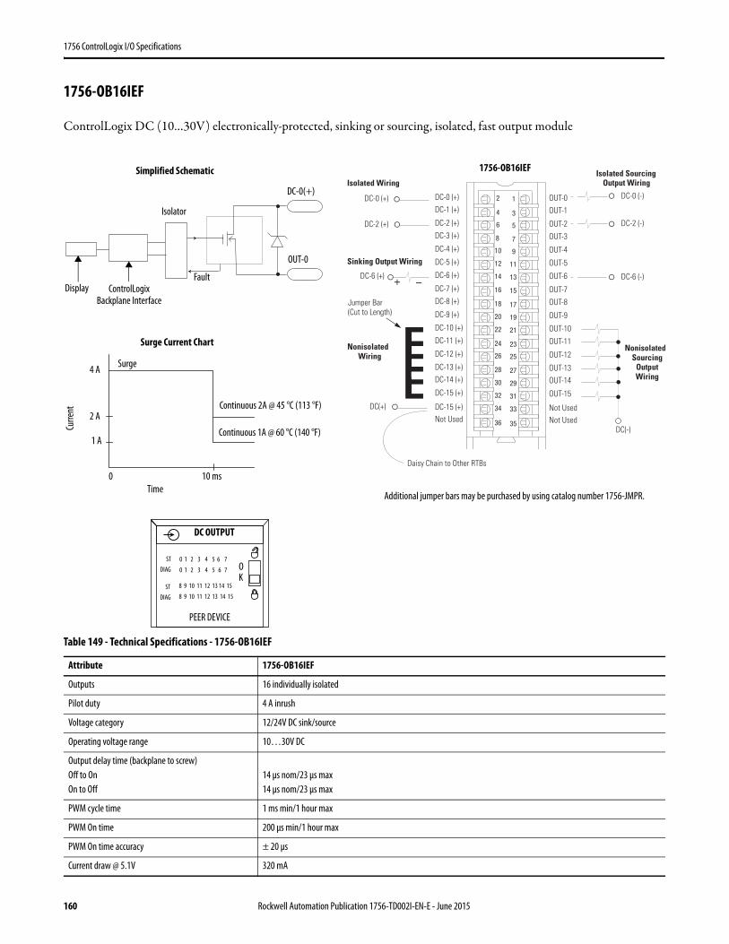
1756 ControlLogix I/O Specifications
1756-OB16IEF
ControlLogix DC (10…30V) electronically-protected, sinking or sourcing, isolated, fast output module
Table 149 - Technical Specifications - 1756-OB16IEF
Attribute 1756-OB16IEF
Outputs 16 individually isolated
Pilot duty 4 A inrush
Voltage category 12/24V DC sink/source
Operating voltage range 10…30V DC
Output delay time (backplane to screw)Off to OnOn to Off
14 μs nom/23 μs max14 μs nom/23 μs max
PWM cycle time 1 ms min/1 hour max
PWM On time 200 μs min/1 hour max
PWM On time accuracy ± 20 μs
Current draw @ 5.1V 320 mA
12
34
56
78
910
1112
1314
1516
1718
1920
2122
2324
2526
2728
2930
3132
3334
3536
+ –
Nonisolated Wiring
Isolated Wiring
Daisy Chain to Other RTBs
DC-0 (+)DC-1 (+)
DC-2 (+)
DC-3 (+)
DC-8 (+)
DC-4 (+)
DC-5 (+)
DC-6 (+)
DC-7 (+)
Not Used
DC-9 (+)
DC-10 (+)
DC-11 (+)
DC-12 (+)
DC-13 (+)DC-14 (+)
DC-15 (+)
DC-15 (+)
OUT-0OUT-1
OUT-2
OUT-3
OUT-8
OUT-4
OUT-5
OUT-6
OUT-7
Not Used
OUT-9
OUT-10
OUT-11
OUT-12
OUT-13OUT-14
OUT-15
Not Used
DC-0 (+)
DC(+)
Jumper Bar (Cut to Length)
DC-2 (+)
DC-6 (+)
Sinking Output Wiring
NonisolatedSourcing
Output Wiring
Isolated Sourcing Output Wiring
DC-0 (-)
DC-2 (-)
DC-6 (-)
DC(-)
ControlLogix Backplane Interface
Continuous 1A @ 60 °C (140 °F)
Display
Surge Current Chart
Simplified Schematic
Surge
Continuous 2A @ 45 °C (113 °F)
OUT-0
DC-0(+)
Curre
nt
Time0 10 ms
2 A
4 A
Additional jumper bars may be purchased by using catalog number 1756-JMPR.
Isolator
Fault
1756-OB16IEF
DC OUTPUT
PEER DEVICE
KO
1 A
0 1 2 3 4 5 6 7
0 1 2 3 4 5 6 7
8 9 10 11 12 13 14 15
8 9 10 11 12 13 14 15
STDIAG
STDIAG
160 Rockwell Automation Publication 1756-TD002I-EN-E - June 2015
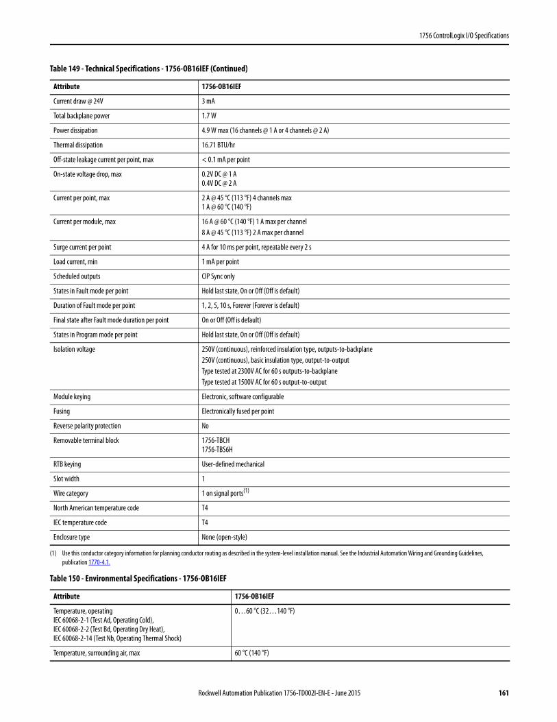
1756 ControlLogix I/O Specifications
Current draw @ 24V 3 mA
Total backplane power 1.7 W
Power dissipation 4.9 W max (16 channels @ 1 A or 4 channels @ 2 A)
Thermal dissipation 16.71 BTU/hr
Off-state leakage current per point, max < 0.1 mA per point
On-state voltage drop, max 0.2V DC @ 1 A0.4V DC @ 2 A
Current per point, max 2 A @ 45 °C (113 °F) 4 channels max1 A @ 60 °C (140 °F)
Current per module, max 16 A @ 60 °C (140 °F) 1 A max per channel8 A @ 45 °C (113 °F) 2 A max per channel
Surge current per point 4 A for 10 ms per point, repeatable every 2 s
Load current, min 1 mA per point
Scheduled outputs CIP Sync only
States in Fault mode per point Hold last state, On or Off (Off is default)
Duration of Fault mode per point 1, 2, 5, 10 s, Forever (Forever is default)
Final state after Fault mode duration per point On or Off (Off is default)
States in Program mode per point Hold last state, On or Off (Off is default)
Isolation voltage 250V (continuous), reinforced insulation type, outputs-to-backplane250V (continuous), basic insulation type, output-to-outputType tested at 2300V AC for 60 s outputs-to-backplaneType tested at 1500V AC for 60 s output-to-output
Module keying Electronic, software configurable
Fusing Electronically fused per point
Reverse polarity protection No
Removable terminal block 1756-TBCH1756-TBS6H
RTB keying User-defined mechanical
Slot width 1
Wire category 1 on signal ports(1)
North American temperature code T4
IEC temperature code T4
Enclosure type None (open-style)
(1) Use this conductor category information for planning conductor routing as described in the system-level installation manual. See the Industrial Automation Wiring and Grounding Guidelines, publication 1770-4.1.
Table 150 - Environmental Specifications - 1756-OB16IEF
Attribute 1756-OB16IEF
Temperature, operatingIEC 60068-2-1 (Test Ad, Operating Cold),IEC 60068-2-2 (Test Bd, Operating Dry Heat),IEC 60068-2-14 (Test Nb, Operating Thermal Shock)
0…60 °C (32…140 °F)
Temperature, surrounding air, max 60 °C (140 °F)
Table 149 - Technical Specifications - 1756-OB16IEF (Continued)
Attribute 1756-OB16IEF
Rockwell Automation Publication 1756-TD002I-EN-E - June 2015 161
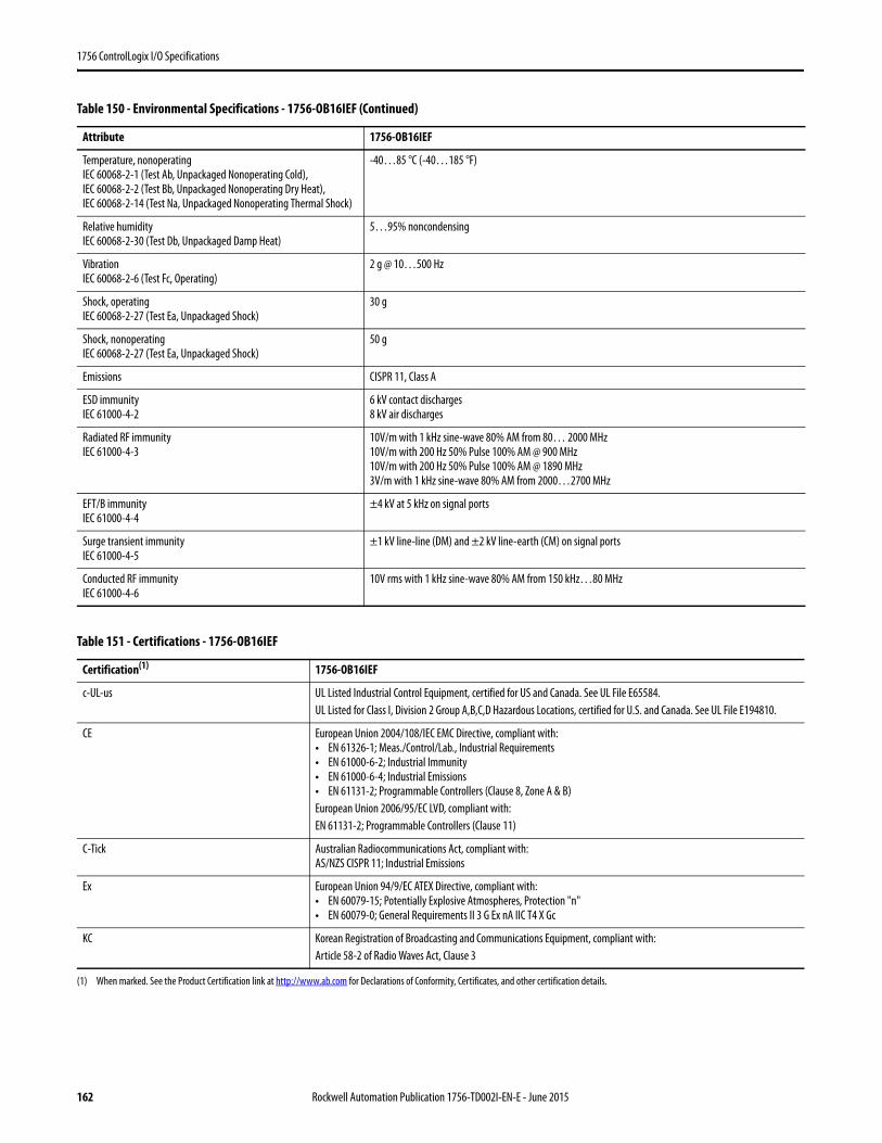
1756 ControlLogix I/O Specifications
Temperature, nonoperatingIEC 60068-2-1 (Test Ab, Unpackaged Nonoperating Cold),IEC 60068-2-2 (Test Bb, Unpackaged Nonoperating Dry Heat),IEC 60068-2-14 (Test Na, Unpackaged Nonoperating Thermal Shock)
-40…85 °C (-40…185 °F)
Relative humidityIEC 60068-2-30 (Test Db, Unpackaged Damp Heat)
5…95% noncondensing
VibrationIEC 60068-2-6 (Test Fc, Operating)
2 g @ 10…500 Hz
Shock, operatingIEC 60068-2-27 (Test Ea, Unpackaged Shock)
30 g
Shock, nonoperatingIEC 60068-2-27 (Test Ea, Unpackaged Shock)
50 g
Emissions CISPR 11, Class A
ESD immunityIEC 61000-4-2
6 kV contact discharges8 kV air discharges
Radiated RF immunityIEC 61000-4-3
10V/m with 1 kHz sine-wave 80% AM from 80… 2000 MHz10V/m with 200 Hz 50% Pulse 100% AM @ 900 MHz10V/m with 200 Hz 50% Pulse 100% AM @ 1890 MHz3V/m with 1 kHz sine-wave 80% AM from 2000…2700 MHz
EFT/B immunityIEC 61000-4-4
±4 kV at 5 kHz on signal ports
Surge transient immunityIEC 61000-4-5
±1 kV line-line (DM) and ±2 kV line-earth (CM) on signal ports
Conducted RF immunityIEC 61000-4-6
10V rms with 1 kHz sine-wave 80% AM from 150 kHz…80 MHz
Table 151 - Certifications - 1756-OB16IEF
Certification(1)
(1) When marked. See the Product Certification link at http://www.ab.com for Declarations of Conformity, Certificates, and other certification details.
1756-OB16IEF
c-UL-us UL Listed Industrial Control Equipment, certified for US and Canada. See UL File E65584.UL Listed for Class I, Division 2 Group A,B,C,D Hazardous Locations, certified for U.S. and Canada. See UL File E194810.
CE European Union 2004/108/IEC EMC Directive, compliant with:• EN 61326-1; Meas./Control/Lab., Industrial Requirements• EN 61000-6-2; Industrial Immunity• EN 61000-6-4; Industrial Emissions• EN 61131-2; Programmable Controllers (Clause 8, Zone A & B)European Union 2006/95/EC LVD, compliant with:EN 61131-2; Programmable Controllers (Clause 11)
C-Tick Australian Radiocommunications Act, compliant with:AS/NZS CISPR 11; Industrial Emissions
Ex European Union 94/9/EC ATEX Directive, compliant with:• EN 60079-15; Potentially Explosive Atmospheres, Protection "n"• EN 60079-0; General Requirements II 3 G Ex nA IIC T4 X Gc
KC Korean Registration of Broadcasting and Communications Equipment, compliant with:Article 58-2 of Radio Waves Act, Clause 3
Table 150 - Environmental Specifications - 1756-OB16IEF (Continued)
Attribute 1756-OB16IEF
162 Rockwell Automation Publication 1756-TD002I-EN-E - June 2015
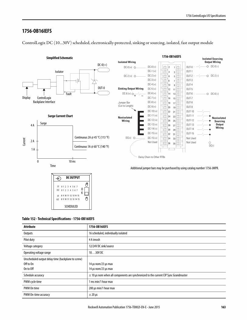
1756 ControlLogix I/O Specifications
1756-OB16IEFS
ControlLogix DC (10…30V) scheduled, electronically-protected, sinking or sourcing, isolated, fast output module
Table 152 - Technical Specifications - 1756-OB16IEFS
Attribute 1756-OB16IEFS
Outputs 16 scheduled, individually isolated
Pilot duty 4 A inrush
Voltage category 12/24V DC sink/source
Operating voltage range 10…30V DC
Unscheduled output delay time (backplane to screw)Off to OnOn to Off
14 μs nom/23 μs max14 μs nom/23 μs max
Schedule accuracy ± 10 μs nom when all components are synchronized to the current CIP Sync Grandmaster
PWM cycle time 1 ms min/1 hour max
PWM On time 200 μs min/1 hour max
PWM On-time accuracy ± 20 μs
12
34
56
78
910
1112
1314
1516
1718
1920
2122
2324
2526
2728
2930
3132
3334
3536
+ –
Nonisolated Wiring
Isolated Wiring
Daisy Chain to Other RTBs
DC-0 (+)DC-1 (+)
DC-2 (+)
DC-3 (+)
DC-8 (+)
DC-4 (+)
DC-5 (+)
DC-6 (+)
DC-7 (+)
Not Used
DC-9 (+)
DC-10 (+)
DC-11 (+)
DC-12 (+)
DC-13 (+)DC-14 (+)
DC-15 (+)
DC-15 (+)
OUT-0OUT-1
OUT-2
OUT-3
OUT-8
OUT-4
OUT-5
OUT-6
OUT-7
Not Used
OUT-9
OUT-10
OUT-11
OUT-12
OUT-13OUT-14
OUT-15
Not Used
DC-0 (+)
DC(+)
Jumper Bar (Cut to Length)
DC-2 (+)
DC-6 (+)
Sinking Output Wiring
NonisolatedSourcing
Output Wiring
Isolated Sourcing Output Wiring
DC-0 (-)
DC-2 (-)
DC-6 (-)
DC(-)
ControlLogix Backplane Interface
Continuous 1A @ 60 °C (140 °F)
Display
Surge Current Chart
Simplified Schematic
Surge
Continuous 2A @ 45 °C (113 °F)
OUT-0
DC-0(+)
Curre
nt
Time0 10 ms
2 A
4 A
Additional jumper bars may be purchased by using catalog number 1756-JMPR.
Isolator
Fault
1756-OB16IEFS
DC OUTPUT
K
0 1 2 3 4 5 6 7
0 1 2 3 4 5 6 7
8 9 10 11 12 13 14 15
8 9 10 11 12 13 14 15
O
1 A
STFLT
STFLT
SCHEDULED
Rockwell Automation Publication 1756-TD002I-EN-E - June 2015 163

1756 ControlLogix I/O Specifications
Current draw @ 5.1V 320 mA
Current draw @ 24V 3 mA
Total backplane power 1.7 W
Power dissipation 4.9 W max (16 channels @ 1 A or 4 channels @ 2 A)
Thermal dissipation 16.71 BTU/hr
Off-state leakage current per point, max < 0.1 mA per point
On-state voltage drop, max 0.2V DC @ 1 A0.4V DC @ 2 A
Current per point, max 2 A @ 45 °C (113 °F) 4 channels max1 A @ 60 °C (140 °F)
Current per module, max 16 A @ 60 °C (140 °F) 1 A max per channel8 A @ 45 °C (113 °F) 2 A max per channel
Surge current per point 4 A for 10 ms per point, repeatable every 2 s
Load current, min 1 mA per point
Scheduled outputs CIP Sync only
States in Fault mode per point Hold last state, On or Off (Off is default)
Duration of Fault mode per point 1, 2, 5, 10 s, Forever (Forever is default)
Final state after Fault mode duration per point On or Off (Off is default)
States in Program mode per point Hold last state, On or Off (Off is default)
Isolation voltage 250V (continuous), reinforced insulation type, outputs-to-backplane250V (continuous), basic insulation type, output-to-outputType tested at 2300V AC for 60 s outputs-to-backplaneType tested at 1500V AC for 60 s output-to-output
Module keying Electronic, software configurable
Fusing Electronically fused per point
Reverse polarity protection No
Removable terminal block 1756-TBCH1756-TBS6H
RTB keying User-defined mechanical
Slot width 1
Wire category 1 on signal ports(1)
North American temperature code T4
IEC temperature code T4
Enclosure type None (open-style)
(1) Use this conductor category information for planning conductor routing as described in the system-level installation manual. See the Industrial Automation Wiring and Grounding Guidelines, publication 1770-4.1.
Table 152 - Technical Specifications - 1756-OB16IEFS (Continued)
Attribute 1756-OB16IEFS
164 Rockwell Automation Publication 1756-TD002I-EN-E - June 2015

1756 ControlLogix I/O Specifications
Table 153 - Environmental Specifications - 1756-OB16IEFS
Attribute 1756-OB16IEFS
Temperature, operatingIEC 60068-2-1 (Test Ad, Operating Cold),IEC 60068-2-2 (Test Bd, Operating Dry Heat),IEC 60068-2-14 (Test Nb, Operating Thermal Shock)
0…60 °C (32…140 °F)
Temperature, surrounding air, max 60 °C (140 °F)
Temperature, nonoperatingIEC 60068-2-1 (Test Ab, Unpackaged Nonoperating Cold),IEC 60068-2-2 (Test Bb, Unpackaged Nonoperating Dry Heat),IEC 60068-2-14 (Test Na, Unpackaged Nonoperating Thermal Shock)
-40…85 °C (-40…185 °F)
Relative humidityIEC 60068-2-30 (Test Db, Unpackaged Damp Heat)
5…95% noncondensing
VibrationIEC 60068-2-6 (Test Fc, Operating)
2 g @ 10…500 Hz
Shock, operatingIEC 60068-2-27 (Test Ea, Unpackaged Shock)
30 g
Shock, nonoperatingIEC 60068-2-27 (Test Ea, Unpackaged Shock)
50 g
Emissions CISPR 11, Class A
ESD immunityIEC 61000-4-2
6 kV contact discharges8 kV air discharges
Radiated RF immunityIEC 61000-4-3
10V/m with 1 kHz sine-wave 80% AM from 80… 2000 MHz10V/m with 200 Hz 50% Pulse 100% AM @ 900 MHz10V/m with 200 Hz 50% Pulse 100% AM @ 1890 MHz3V/m with 1 kHz sine-wave 80% AM from 2000…2700 MHz
EFT/B immunityIEC 61000-4-4
±4 kV at 5 kHz on signal ports
Surge transient immunityIEC 61000-4-5
±1 kV line-line (DM) and ±2 kV line-earth (CM) on signal ports
Conducted RF immunityIEC 61000-4-6
10V rms with 1 kHz sine-wave 80% AM from 150 kHz…80 MHz
Table 154 - Certifications - 1756-OB16IEFS
Certification(1)
(1) When marked. See the Product Certification link at http://www.ab.com for Declarations of Conformity, Certificates, and other certification details.
1756-OB16IEFS
c-UL-us UL Listed Industrial Control Equipment, certified for US and Canada. See UL File E65584.UL Listed for Class I, Division 2 Group A,B,C,D Hazardous Locations, certified for U.S. and Canada. See UL File E194810.
CE European Union 2004/108/IEC EMC Directive, compliant with:• EN 61326-1; Meas./Control/Lab., Industrial Requirements• EN 61000-6-2; Industrial Immunity• EN 61000-6-4; Industrial Emissions• EN 61131-2; Programmable Controllers (Clause 8, Zone A & B)European Union 2006/95/EC LVD, compliant with:EN 61131-2; Programmable Controllers (Clause 11)
C-Tick Australian Radiocommunications Act, compliant with:AS/NZS CISPR 11; Industrial Emissions
Ex European Union 94/9/EC ATEX Directive, compliant with:• EN 60079-15; Potentially Explosive Atmospheres, Protection "n"• EN 60079-0; General Requirements II 3 G Ex nA IIC T4 X Gc
KC Korean Registration of Broadcasting and Communications Equipment, compliant with:Article 58-2 of Radio Waves Act, Clause 3
Rockwell Automation Publication 1756-TD002I-EN-E - June 2015 165
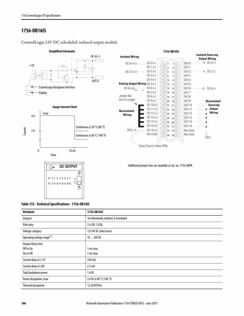
1756 ControlLogix I/O Specifications
1756-OB16IS
ControlLogix 24V DC scheduled, isolated output module
Table 155 - Technical Specifications - 1756-OB16IS
Attribute 1756-OB16IS
Outputs 16 individually isolated, 8 scheduled
Pilot duty 2 A (DC-13SQ)
Voltage category 12/24V DC sink/source
Operating voltage range(1) 10…30V DC
Output delay timeOff to OnOn to Off
1 ms max 2 ms max
Current draw @ 5.1V 350 mA
Current draw @ 24V 2.5 mA
Total backplane power 1.8 W
Power dissipation, max 3.6 W @ 60 °C (140 °F)
Thermal dissipation 12.28 BTU/hr
12
34
56
78
910
1112
1314
1516
1718
1920
2122
2324
2526
2728
2930
3132
3334
3536
+ –
Nonisolated Wiring
Isolated Wiring
Daisy Chain to Other RTBs
DC-0 (+)DC-1 (+)DC-2 (+)DC-3 (+)
DC-8 (+)
DC-4 (+)DC-5 (+)DC-6 (+)DC-7 (+)
Not Used
DC-9 (+)DC-10 (+)DC-11 (+)DC-12 (+)DC-13 (+)DC-14 (+)DC-15 (+)DC-15 (+)
OUT-0OUT-1OUT-2OUT-3
OUT-8
OUT-4OUT-5OUT-6OUT-7
Not Used
OUT-9OUT-10OUT-11OUT-12OUT-13OUT-14OUT-15Not Used
DC-0 (+)
DC(+)
Jumper Bar (Cut to Length)
DC-2 (+)
DC-6 (+)
Sinking Output Wiring
NonisolatedSourcing
Output Wiring
Isolated Sourcing Output Wiring
DC-0 (-)
DC-2 (-)
DC-6 (-)
DC(-)
ControlLogix Backplane Interface
Continuous @ 60 °C (140 °F)
Display
Surge Current Chart
Simplified Schematic
Surge
Continuous @ 30 °C (86 °F)
OUT-0
DC-0(+)
Curre
nt
Time0 10 ms
2 A
4 A
+5V
Additional jumper bars are available as cat. no. 1756-JMPR.DC OUTPUT
ST 0 1 2 3 4 5 6 7
ST 8 9 10 11 1213 14 15
OK
1756-OB16IS
166 Rockwell Automation Publication 1756-TD002I-EN-E - June 2015
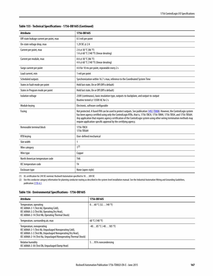
1756 ControlLogix I/O Specifications
Off-state leakage current per point, max 0.5 mA per point
On-state voltage drop, max 1.2V DC @ 2 A
Current per point, max 2 A @ 30 °C (86 °F)1 A @ 60 °C (140 °F) (linear derating)
Current per module, max 8 A @ 30 °C (86 °F)4 A @ 60 °C (140 °F) (linear derating)
Surge current per point 4 A for 10 ms per point, repeatable every 2 s
Load current, min 1 mA per point
Scheduled outputs Synchronization within 16.7 s max, reference to the Coordinated System Time
States in Fault mode per point Hold last state, On or Off (Off is default)
States in Program mode per point Hold last state, On or Off (Off is default)
Isolation voltage 250V (continuous), basic insulation type, outputs-to-backplane, and output-to-outputRoutine tested @ 1350V AC for 2 s
Module keying Electronic, software configurable
Fusing Not protected. A fused IFM can be used to protect outputs. See publication 1492-TD008. However, the ControlLogix system has been agency certified using only the ControlLogix RTBs, that is, 1756-TBCH, 1756-TBNH, 1756-TBSH, and 1756-TBS6H. Any application that requires agency certification of the ControlLogix system using other wiring termination methods may require application-specific approval by the certifying agency.
Removable terminal block 1756-TBCH1756-TBS6H
RTB keying User-defined mechanical
Slot width 1
Wire category 1(2)
Wire type Copper
North American temperature code T4A
IEC temperature code T4
Enclosure type None (open-style)
(1) UL certification for 24V DC nominal. Rockwell Automation specified to 10…30V DC(2) Use this conductor category information for planning conductor routing as described in the system-level installation manual. See the Industrial Automation Wiring and Grounding Guidelines,
publication 1770-4.1.
Table 156 - Environmental Specifications - 1756-OB16IS
Attribute 1756-OB16IS
Temperature, operatingIEC 60068-2-1 (Test Ad, Operating Cold),IEC 60068-2-2 (Test Bd, Operating Dry Heat),IEC 60068-2-14 (Test Nb, Operating Thermal Shock)
0…60 °C (32…140 °F)
Temperature, surrounding air, max 60 °C (140 °F)
Temperature, nonoperatingIEC 60068-2-1 (Test Ab, Unpackaged Nonoperating Cold),IEC 60068-2-2 (Test Bb, Unpackaged Nonoperating Dry Heat),IEC 60068-2-14 (Test Na, Unpackaged Nonoperating Thermal Shock)
-40…85 °C (-40…185 °F)
Relative humidityIEC 60068-2-30 (Test Db, Unpackaged Damp Heat)
5…95% noncondensing
Table 155 - Technical Specifications - 1756-OB16IS (Continued)
Attribute 1756-OB16IS
Rockwell Automation Publication 1756-TD002I-EN-E - June 2015 167
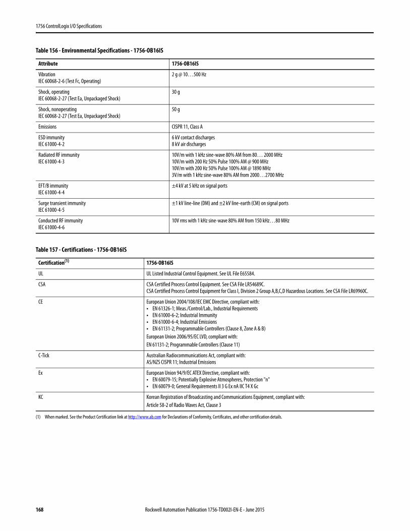
1756 ControlLogix I/O Specifications
VibrationIEC 60068-2-6 (Test Fc, Operating)
2 g @ 10…500 Hz
Shock, operatingIEC 60068-2-27 (Test Ea, Unpackaged Shock)
30 g
Shock, nonoperatingIEC 60068-2-27 (Test Ea, Unpackaged Shock)
50 g
Emissions CISPR 11, Class A
ESD immunityIEC 61000-4-2
6 kV contact discharges8 kV air discharges
Radiated RF immunityIEC 61000-4-3
10V/m with 1 kHz sine-wave 80% AM from 80… 2000 MHz10V/m with 200 Hz 50% Pulse 100% AM @ 900 MHz10V/m with 200 Hz 50% Pulse 100% AM @ 1890 MHz3V/m with 1 kHz sine-wave 80% AM from 2000…2700 MHz
EFT/B immunityIEC 61000-4-4
±4 kV at 5 kHz on signal ports
Surge transient immunityIEC 61000-4-5
±1 kV line-line (DM) and ±2 kV line-earth (CM) on signal ports
Conducted RF immunityIEC 61000-4-6
10V rms with 1 kHz sine-wave 80% AM from 150 kHz…80 MHz
Table 157 - Certifications - 1756-OB16IS
Certification(1)
(1) When marked. See the Product Certification link at http://www.ab.com for Declarations of Conformity, Certificates, and other certification details.
1756-OB16IS
UL UL Listed Industrial Control Equipment. See UL File E65584.
CSA CSA Certified Process Control Equipment. See CSA File LR54689C.CSA Certified Process Control Equipment for Class I, Division 2 Group A,B,C,D Hazardous Locations. See CSA File LR69960C.
CE European Union 2004/108/IEC EMC Directive, compliant with:• EN 61326-1; Meas./Control/Lab., Industrial Requirements• EN 61000-6-2; Industrial Immunity• EN 61000-6-4; Industrial Emissions• EN 61131-2; Programmable Controllers (Clause 8, Zone A & B)European Union 2006/95/EC LVD, compliant with:EN 61131-2; Programmable Controllers (Clause 11)
C-Tick Australian Radiocommunications Act, compliant with:AS/NZS CISPR 11; Industrial Emissions
Ex European Union 94/9/EC ATEX Directive, compliant with:• EN 60079-15; Potentially Explosive Atmospheres, Protection "n"• EN 60079-0; General Requirements II 3 G Ex nA IIC T4 X Gc
KC Korean Registration of Broadcasting and Communications Equipment, compliant with:Article 58-2 of Radio Waves Act, Clause 3
Table 156 - Environmental Specifications - 1756-OB16IS
Attribute 1756-OB16IS
168 Rockwell Automation Publication 1756-TD002I-EN-E - June 2015

1756 ControlLogix I/O Specifications
1756-OB32
ControlLogix DC (10…31.2V) output module
Table 158 - Technical Specifications - 1756-OB32
Attribute 1756-OB32
Outputs 32 (16 points/group)
Voltage category 12/24V DC source
Operating voltage range 10…31.2V DC
Output delay timeOff to OnOn to Off
60 μs nom/1 ms max 200 μs nom/1 ms max
Current draw @ 5.1V 300 mA
Current draw @ 24V 2 mA
Total backplane power 1.58 W
Power dissipation, max 4.8 W @ 60 °C (140 °F)
Thermal dissipation 16.37 BTU/hr
Off-state leakage current per point, max 0.5 mA per point
On-state voltage drop, max 200 mV DC @ 0.5 A
12
34
56
78
910
1112
1314
1516
1718
1920
2122
2324
2526
2728
2930
3132
3334
3536
+ _
Daisy Chain to Other RTBs
Group 0
Group 1
Group 0
Group 1
DC COM
OUT-1OUT-3OUT-5OUT-7OUT-9OUT-11
OUT-13OUT-15DC-0(+)
DC-1(+)
OUT-0OUT-2OUT-4OUT-6OUT-8OUT-10
OUT-12OUT-14RTN OUT-0
RTN OUT-1
OUT-17OUT-19OUT-21OUT-23OUT-25OUT-27
OUT-29OUT-31
OUT-16OUT-18OUT-20OUT-22OUT-24OUT-26
OUT-28OUT-30
Continuous @ 60 °C (140 °F)
+5V
RTN OUT-0
OUT-0
DC-0(+)
ControlLogix Backplane Interface
Display
Surge Current Chart
Simplified Schematic
Surge
Curre
nt
Time0 10 ms
0.5 A
1 A
DC OUTPUT
OK
ST 0 1 2 3 4 5 6 7
ST 8 910 21 3 4 5
1 1 1 11
ST 6 718 09 1 2 3
1 2 2 221 1
ST 4 526 87 9 0 1
2 2 2 332 2
1756-OB32
Rockwell Automation Publication 1756-TD002I-EN-E - June 2015 169

1756 ControlLogix I/O Specifications
Current per point, max 0.5 A @ 50 °C (122 °F) linear derating0.35 A @ 60 °C (140 °F)
Current per module, max 16 A @ 50 °C (122 °F) linear derating10 A @ 60 °C (140 °F)
Surge current per point, max 1 A for 10 ms per point, repeatable every 2 s @ 60 °C (140 °F)
Load current, min 3 mA per point
Scheduled outputs Synchronization within 16.7 s max, reference to the Coordinated System Time
States in Fault mode per point Hold last state, On or Off (Off is default)
States in Program mode per point Hold last state, On or Off (Off is default)
Isolation voltage 250V (continuous), basic insulation type, outputs-to-backplane, and output group-to-groupNo isolation between individual group outputsRoutine tested @ 1350V AC for 2 s
Module keying Electronic, software configurable
Fusing Not protected. A fused IFM can be used to protect outputs. See publication 1492-TD008. However, the ControlLogix system has been agency certified using only the ControlLogix RTBs, that is, 1756-TBCH, 1756-TBNH, 1756-TBSH, and 1756-TBS6H. Any application that requires agency certification of the ControlLogix system using other wiring termination methods may require application-specific approval by the certifying agency.
Removable terminal block 1756-TBCH1756-TBS6H
RTB keying User-defined mechanical
Slot width 1
Wire category 1(1)
North American temperature code T3C
IEC temperature code T3
Enclosure type None (open-style)
(1) Use this conductor category information for planning conductor routing as described in the system-level installation manual. See the Industrial Automation Wiring and Grounding Guidelines, publication 1770-4.1.
Table 159 - Environmental Specifications - 1756-OB32
Attribute 1756-OB32
Temperature, operatingIEC 60068-2-1 (Test Ad, Operating Cold),IEC 60068-2-2 (Test Bd, Operating Dry Heat),IEC 60068-2-14 (Test Nb, Operating Thermal Shock)
0…60 °C (32…140 °F)
Temperature, surrounding air, max 60 °C (140 °F)
Temperature, nonoperatingIEC 60068-2-1 (Test Ab, Unpackaged Nonoperating Cold),IEC 60068-2-2 (Test Bb, Unpackaged Nonoperating Dry Heat),IEC 60068-2-14 (Test Na, Unpackaged Nonoperating Thermal Shock)
-40…85 °C (-40…185 °F)
Relative humidityIEC 60068-2-30 (Test Db, Unpackaged Damp Heat)
5…95% noncondensing
VibrationIEC 60068-2-6 (Test Fc, Operating)
2 g @ 10…500 Hz
Shock, operatingIEC 60068-2-27 (Test Ea, Unpackaged Shock)
30 g
Table 158 - Technical Specifications - 1756-OB32 (Continued)
Attribute 1756-OB32
170 Rockwell Automation Publication 1756-TD002I-EN-E - June 2015
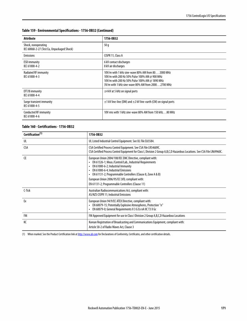
1756 ControlLogix I/O Specifications
Shock, nonoperatingIEC 60068-2-27 (Test Ea, Unpackaged Shock)
50 g
Emissions CISPR 11, Class A
ESD immunityIEC 61000-4-2
6 kV contact discharges8 kV air discharges
Radiated RF immunityIEC 61000-4-3
10V/m with 1 kHz sine-wave 80% AM from 80… 2000 MHz10V/m with 200 Hz 50% Pulse 100% AM @ 900 MHz10V/m with 200 Hz 50% Pulse 100% AM @ 1890 MHz3V/m with 1 kHz sine-wave 80% AM from 2000…2700 MHz
EFT/B immunityIEC 61000-4-4
±4 kV at 5 kHz on signal ports
Surge transient immunityIEC 61000-4-5
±1 kV line-line (DM) and ±2 kV line-earth (CM) on signal ports
Conducted RF immunityIEC 61000-4-6
10V rms with 1 kHz sine-wave 80% AM from 150 kHz…80 MHz
Table 160 - Certifications - 1756-OB32
Certification(1) 1756-OB32
UL UL Listed Industrial Control Equipment. See UL File E65584.
CSA CSA Certified Process Control Equipment. See CSA File LR54689C.CSA Certified Process Control Equipment for Class I, Division 2 Group A,B,C,D Hazardous Locations. See CSA File LR69960C.
CE European Union 2004/108/IEC EMC Directive, compliant with:• EN 61326-1; Meas./Control/Lab., Industrial Requirements• EN 61000-6-2; Industrial Immunity• EN 61000-6-4; Industrial Emissions• EN 61131-2; Programmable Controllers (Clause 8, Zone A & B)European Union 2006/95/EC LVD, compliant with:EN 61131-2; Programmable Controllers (Clause 11)
C-Tick Australian Radiocommunications Act, compliant with:AS/NZS CISPR 11; Industrial Emissions
Ex European Union 94/9/EC ATEX Directive, compliant with:• EN 60079-15; Potentially Explosive Atmospheres, Protection "n"• EN 60079-0; General Requirements II 3 G Ex nA IIC T3 X Gc
FM FM Approved Equipment for use in Class I Division 2 Group A,B,C,D Hazardous Locations
KC Korean Registration of Broadcasting and Communications Equipment, compliant with:Article 58-2 of Radio Waves Act, Clause 3
(1) When marked. See the Product Certification link at http://www.ab.com for Declarations of Conformity, Certificates, and other certification details.
Table 159 - Environmental Specifications - 1756-OB32 (Continued)
Attribute 1756-OB32
Rockwell Automation Publication 1756-TD002I-EN-E - June 2015 171
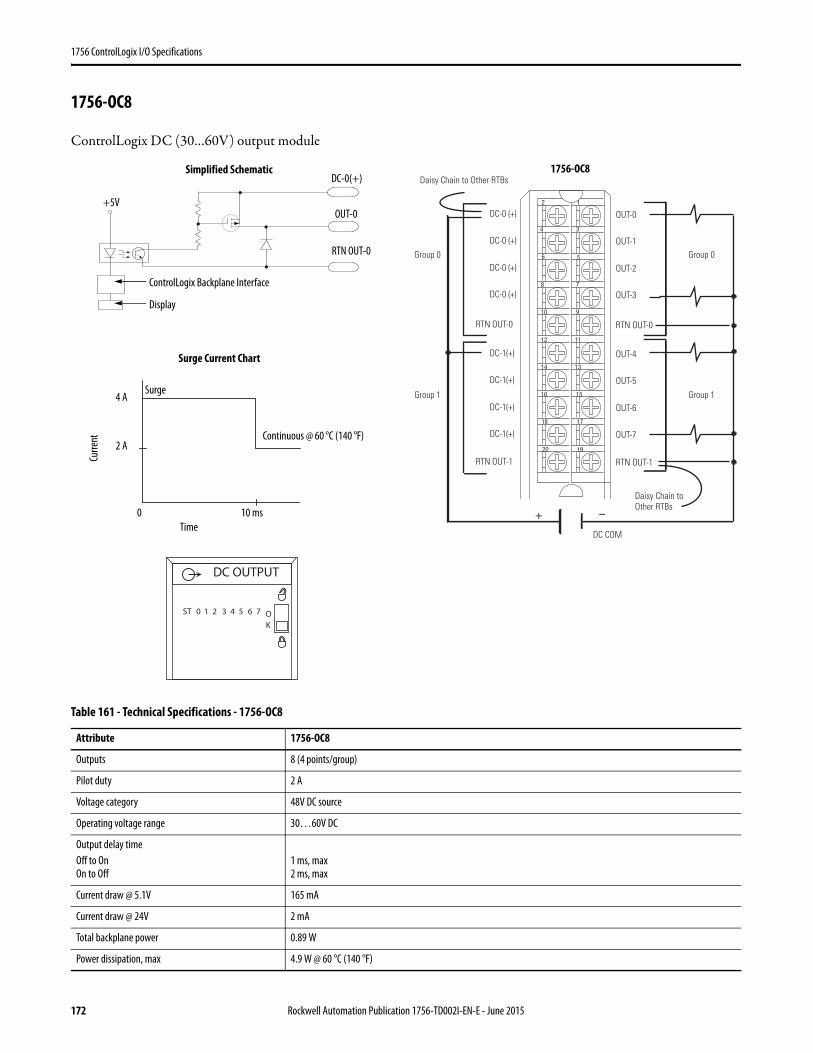
1756 ControlLogix I/O Specifications
1756-OC8
ControlLogix DC (30…60V) output module
Table 161 - Technical Specifications - 1756-OC8
Attribute 1756-OC8
Outputs 8 (4 points/group)
Pilot duty 2 A
Voltage category 48V DC source
Operating voltage range 30…60V DC
Output delay timeOff to OnOn to Off
1 ms, max 2 ms, max
Current draw @ 5.1V 165 mA
Current draw @ 24V 2 mA
Total backplane power 0.89 W
Power dissipation, max 4.9 W @ 60 °C (140 °F)
12
34
56
78
910
1112
1314
1516
1718
1920
+ –
Group 0
Group 1
Daisy Chain to Other RTBs
Daisy Chain to Other RTBs
Group 0
Group 1
DC-0 (+)
DC-0 (+)
DC-0 (+)
DC-0 (+)
DC-1(+)
DC-1(+)
DC-1(+)
DC-1(+)
RTN OUT-0
RTN OUT-1
OUT-0
OUT-1
OUT-2
OUT-3
OUT-4
OUT-5
OUT-6
OUT-7
RTN OUT-0
RTN OUT-1
DC COM
Continuous @ 60 °C (140 °F)
+5V
RTN OUT-0
OUT-0
DC-0(+)
ControlLogix Backplane Interface
Display
Surge Current Chart
Simplified Schematic
Surge
Curre
nt
Time0 10 ms
2 A
4 A
DC OUTPUT
ST 0 1 2 3 4 5 6 7 OK
1756-OC8
172 Rockwell Automation Publication 1756-TD002I-EN-E - June 2015
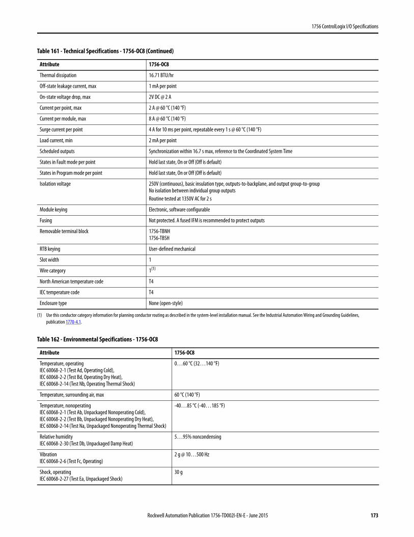
1756 ControlLogix I/O Specifications
Thermal dissipation 16.71 BTU/hr
Off-state leakage current, max 1 mA per point
On-state voltage drop, max 2V DC @ 2 A
Current per point, max 2 A @ 60 °C (140 °F)
Current per module, max 8 A @ 60 °C (140 °F)
Surge current per point 4 A for 10 ms per point, repeatable every 1 s @ 60 °C (140 °F)
Load current, min 2 mA per point
Scheduled outputs Synchronization within 16.7 s max, reference to the Coordinated System Time
States in Fault mode per point Hold last state, On or Off (Off is default)
States in Program mode per point Hold last state, On or Off (Off is default)
Isolation voltage 250V (continuous), basic insulation type, outputs-to-backplane, and output group-to-groupNo isolation between individual group outputsRoutine tested at 1350V AC for 2 s
Module keying Electronic, software configurable
Fusing Not protected. A fused IFM is recommended to protect outputs
Removable terminal block 1756-TBNH1756-TBSH
RTB keying User-defined mechanical
Slot width 1
Wire category 1(1)
North American temperature code T4
IEC temperature code T4
Enclosure type None (open-style)
(1) Use this conductor category information for planning conductor routing as described in the system-level installation manual. See the Industrial Automation Wiring and Grounding Guidelines, publication 1770-4.1.
Table 162 - Environmental Specifications - 1756-OC8
Attribute 1756-OC8
Temperature, operatingIEC 60068-2-1 (Test Ad, Operating Cold),IEC 60068-2-2 (Test Bd, Operating Dry Heat),IEC 60068-2-14 (Test Nb, Operating Thermal Shock)
0…60 °C (32…140 °F)
Temperature, surrounding air, max 60 °C (140 °F)
Temperature, nonoperatingIEC 60068-2-1 (Test Ab, Unpackaged Nonoperating Cold),IEC 60068-2-2 (Test Bb, Unpackaged Nonoperating Dry Heat),IEC 60068-2-14 (Test Na, Unpackaged Nonoperating Thermal Shock)
-40…85 °C (-40…185 °F)
Relative humidityIEC 60068-2-30 (Test Db, Unpackaged Damp Heat)
5…95% noncondensing
VibrationIEC 60068-2-6 (Test Fc, Operating)
2 g @ 10…500 Hz
Shock, operatingIEC 60068-2-27 (Test Ea, Unpackaged Shock)
30 g
Table 161 - Technical Specifications - 1756-OC8 (Continued)
Attribute 1756-OC8
Rockwell Automation Publication 1756-TD002I-EN-E - June 2015 173
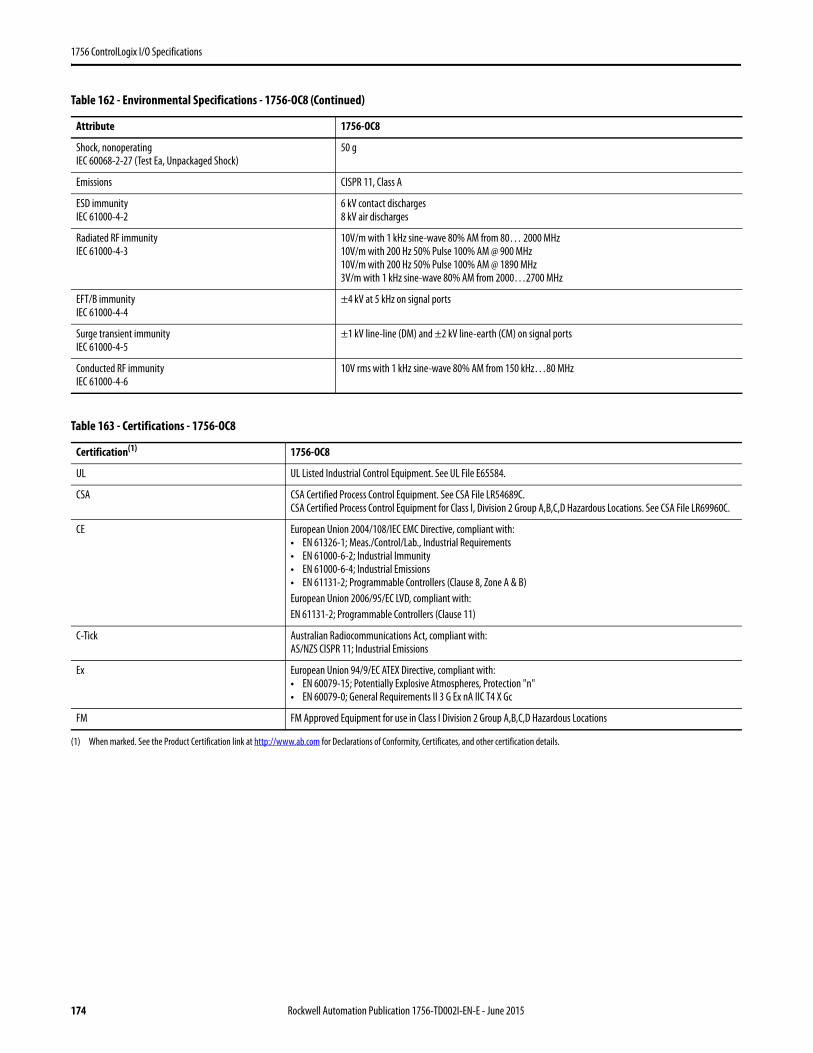
1756 ControlLogix I/O Specifications
Shock, nonoperatingIEC 60068-2-27 (Test Ea, Unpackaged Shock)
50 g
Emissions CISPR 11, Class A
ESD immunityIEC 61000-4-2
6 kV contact discharges8 kV air discharges
Radiated RF immunityIEC 61000-4-3
10V/m with 1 kHz sine-wave 80% AM from 80… 2000 MHz10V/m with 200 Hz 50% Pulse 100% AM @ 900 MHz10V/m with 200 Hz 50% Pulse 100% AM @ 1890 MHz3V/m with 1 kHz sine-wave 80% AM from 2000…2700 MHz
EFT/B immunityIEC 61000-4-4
±4 kV at 5 kHz on signal ports
Surge transient immunityIEC 61000-4-5
±1 kV line-line (DM) and ±2 kV line-earth (CM) on signal ports
Conducted RF immunityIEC 61000-4-6
10V rms with 1 kHz sine-wave 80% AM from 150 kHz…80 MHz
Table 163 - Certifications - 1756-OC8
Certification(1)
(1) When marked. See the Product Certification link at http://www.ab.com for Declarations of Conformity, Certificates, and other certification details.
1756-OC8
UL UL Listed Industrial Control Equipment. See UL File E65584.
CSA CSA Certified Process Control Equipment. See CSA File LR54689C.CSA Certified Process Control Equipment for Class I, Division 2 Group A,B,C,D Hazardous Locations. See CSA File LR69960C.
CE European Union 2004/108/IEC EMC Directive, compliant with:• EN 61326-1; Meas./Control/Lab., Industrial Requirements• EN 61000-6-2; Industrial Immunity• EN 61000-6-4; Industrial Emissions• EN 61131-2; Programmable Controllers (Clause 8, Zone A & B)European Union 2006/95/EC LVD, compliant with:EN 61131-2; Programmable Controllers (Clause 11)
C-Tick Australian Radiocommunications Act, compliant with:AS/NZS CISPR 11; Industrial Emissions
Ex European Union 94/9/EC ATEX Directive, compliant with:• EN 60079-15; Potentially Explosive Atmospheres, Protection "n"• EN 60079-0; General Requirements II 3 G Ex nA IIC T4 X Gc
FM FM Approved Equipment for use in Class I Division 2 Group A,B,C,D Hazardous Locations
Table 162 - Environmental Specifications - 1756-OC8 (Continued)
Attribute 1756-OC8
174 Rockwell Automation Publication 1756-TD002I-EN-E - June 2015
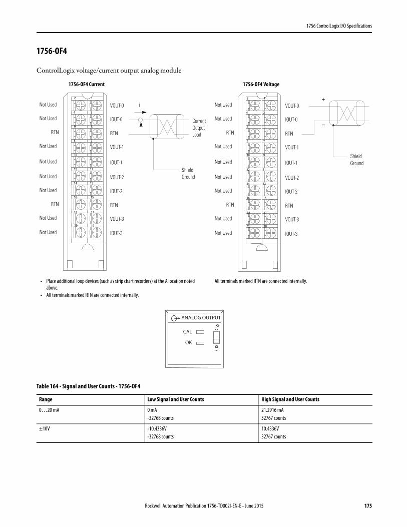
1756 ControlLogix I/O Specifications
1756-OF4
ControlLogix voltage/current output analog module
Table 164 - Signal and User Counts - 1756-OF4
Range Low Signal and User Counts High Signal and User Counts
0…20 mA 0 mA-32768 counts
21.2916 mA32767 counts
±10V -10.4336V-32768 counts
10.4336V32767 counts
12
34
56
78
910
1112
1314
1516
1718
1920
i
Current Output Load
Shield Ground
Not Used
Not Used
RTN
Not Used
Not Used
Not Used
RTN
Not Used
Not Used
Not Used
VOUT-0
IOUT-0
RTN
VOUT-1
VOUT-2
IOUT-2
RTN
VOUT-3
IOUT-1
IOUT-3
A
12
34
56
78
910
1112
1314
1516
1718
1920
+
–
Shield Ground
Not Used
Not Used
RTN
Not Used
Not Used
Not Used
RTN
Not Used
Not Used
Not Used
VOUT-0
IOUT-0
RTN
VOUT-1
VOUT-2
IOUT-2
RTN
VOUT-3
IOUT-1
IOUT-3
• Place additional loop devices (such as strip chart recorders) at the A location noted above.
• All terminals marked RTN are connected internally.
All terminals marked RTN are connected internally.
ANALOG OUTPUT
CAL
OK
1756-OF4 Current 1756-OF4 Voltage
Rockwell Automation Publication 1756-TD002I-EN-E - June 2015 175
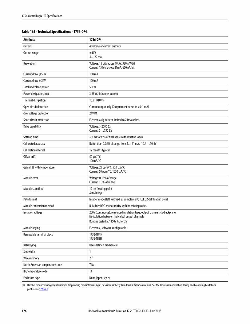
1756 ControlLogix I/O Specifications
Table 165 - Technical Specifications - 1756-OF4
Attribute 1756-OF4
Outputs 4 voltage or current outputs
Output range ±10V4…20 mA
Resolution Voltage: 15 bits across 10.5V, 320 μV/bitCurrent: 15 bits across 21mA, 650 nA/bit
Current draw @ 5.1V 150 mA
Current draw @ 24V 120 mA
Total backplane power 5.8 W
Power dissipation, max 3.25 W, 4 channel current
Thermal dissipation 10.91 BTU/hr
Open circuit detection Current output only (Output must be set to >0.1 mA)
Overvoltage protection 24V DC
Short circuit protection Electronically current limited to 21mA or less
Drive capability Voltage: >2000 ΩCurrent: 0…750 Ω
Settling time <2 ms to 95% of final value with resistive loads
Calibrated accuracy Better than 0.05% of range from 4…21 mA, -10.4…10.4V
Calibration interval 12 months typical
Offset drift 50 μV/ °C100 nA/°C
Gain drift with temperature Voltage: 25 ppm/°C, 520 μV/°CCurrent: 50 ppm/°C, 1050 μA/°C
Module error Voltage: 0.15% of rangeCurrent: 0.3% of range
Module scan time 12 ms floating point8 ms integer
Data format Integer mode (left justified, 2s complement) IEEE 32-bit floating point
Module conversion method R-Ladder DAC, monotonicity with no missing codes
Isolation voltage 250V (continuous), reinforced insulation type, output channels-to-backplaneNo isolation between individual output channelsRoutine tested at 1350V AC for 2 s
Module keying Electronic, software configurable
Removable terminal block 1756-TBNH1756-TBSH
RTB keying User-defined mechanical
Slot width 1
Wire category 2(1)
(1) Use this conductor category information for planning conductor routing as described in the system-level installation manual. See the Industrial Automation Wiring and Grounding Guidelines, publication 1770-4.1.
North American temperature code T4A
IEC temperature code T4
Enclosure type None (open-style)
176 Rockwell Automation Publication 1756-TD002I-EN-E - June 2015

1756 ControlLogix I/O Specifications
Table 166 - Environmental Specifications - 1756-OF4
Attribute 1756-OF4
Temperature, operatingIEC 60068-2-1 (Test Ad, Operating Cold),IEC 60068-2-2 (Test Bd, Operating Dry Heat),IEC 60068-2-14 (Test Nb, Operating Thermal Shock)
0…60 °C (32…140 °F)
Temperature, surrounding air, max 60 °C (140 °F)
Temperature, nonoperatingIEC 60068-2-1 (Test Ab, Unpackaged Nonoperating Cold),IEC 60068-2-2 (Test Bb, Unpackaged Nonoperating Dry Heat),IEC 60068-2-14 (Test Na, Unpackaged Nonoperating Thermal Shock)
-40…85 °C (-40…185 °F)
Relative humidityIEC 60068-2-30 (Test Db, Unpackaged Damp Heat)
5…95% noncondensing
VibrationIEC 60068-2-6 (Test Fc, Operating)
2 g @ 10…500 Hz
Shock, operatingIEC 60068-2-27 (Test Ea, Unpackaged Shock)
30 g
Shock, nonoperatingIEC 60068-2-27 (Test Ea, Unpackaged Shock)
50 g
Emissions CISPR 11, Class A
ESD immunityIEC 61000-4-2
6 kV contact discharges8 kV air discharges
Radiated RF immunityIEC 61000-4-3
10V/m with 1 kHz sine-wave 80% AM from 80… 2000 MHz10V/m with 200 Hz 50% Pulse 100% AM @ 900 MHz10V/m with 200 Hz 50% Pulse 100% AM @ 1890 MHz3V/m with 1 kHz sine-wave 80% AM from 2000…2700 MHz
EFT/B immunityIEC 61000-4-4
±2 kV at 5 kHz on shielded signal ports
Surge transient immunityIEC 61000-4-5
±2 kV line-earth (CM) on shielded signal ports
Conducted RF immunityIEC 61000-4-6
10V rms with 1 kHz sine-wave 80% AM from 150 kHz…80 MHz on shielded signal ports
Rockwell Automation Publication 1756-TD002I-EN-E - June 2015 177
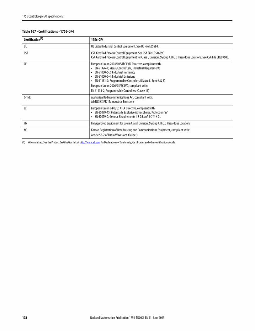
1756 ControlLogix I/O Specifications
Table 167 - Certifications - 1756-OF4
Certification(1) 1756-OF4
UL UL Listed Industrial Control Equipment. See UL File E65584.
CSA CSA Certified Process Control Equipment. See CSA File LR54689C.CSA Certified Process Control Equipment for Class I, Division 2 Group A,B,C,D Hazardous Locations. See CSA File LR69960C.
CE European Union 2004/108/IEC EMC Directive, compliant with:• EN 61326-1; Meas./Control/Lab., Industrial Requirements• EN 61000-6-2; Industrial Immunity• EN 61000-6-4; Industrial Emissions• EN 61131-2; Programmable Controllers (Clause 8, Zone A & B)European Union 2006/95/EC LVD, compliant with:EN 61131-2; Programmable Controllers (Clause 11)
C-Tick Australian Radiocommunications Act, compliant with:AS/NZS CISPR 11; Industrial Emissions
Ex European Union 94/9/EC ATEX Directive, compliant with:• EN 60079-15; Potentially Explosive Atmospheres, Protection "n"• EN 60079-0; General Requirements II 3 G Ex nA IIC T4 X Gc
FM FM Approved Equipment for use in Class I Division 2 Group A,B,C,D Hazardous Locations
KC Korean Registration of Broadcasting and Communications Equipment, compliant with:Article 58-2 of Radio Waves Act, Clause 3
(1) When marked. See the Product Certification link at http://www.ab.com for Declarations of Conformity, Certificates, and other certification details.
178 Rockwell Automation Publication 1756-TD002I-EN-E - June 2015
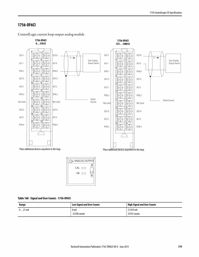
1756 ControlLogix I/O Specifications
1756-OF6CI
ControlLogix current loop output analog module
Table 168 - Signal and User Counts - 1756-OF6CI
Range Low Signal and User Counts High Signal and User Counts
0…21 mA 0 mA-32768 counts
21.074 mA32767 counts
12
34
56
78
910
1112
1314
1516
1718
1920
iOUT-1
ALT-1
RTN-1
OUT-3
RTN-3
Not Used
OUT-5
ALT-5
ALT-3
RTN-5
OUT-0
ALT-0
RTN-0
OUT-2
RTN-2
Not Used
OUT-4
ALT-4
ALT-2
RTN-4
User Analog Output Device
Shield Ground
12
34
56
78
910
1112
1314
1516
1718
1920
iOUT-1
ALT-1
RTN-1
OUT-3
RTN-3
Not Used
OUT-5
ALT-5
ALT-3
RTN-5
OUT-0
ALT-0
RTN-0
OUT-2
RTN-2
Not Used
OUT-4
ALT-4
ALT-2
RTN-4
User Analog Output Device
Shield Ground
Place additional devices anywhere in the loop. Place additional devices anywhere in the loop.
ANALOG OUTPUT
CAL
OK
1756-OF6CI 0…550 Ω
1756-OF6CI 551…1000 Ω
Rockwell Automation Publication 1756-TD002I-EN-E - June 2015 179
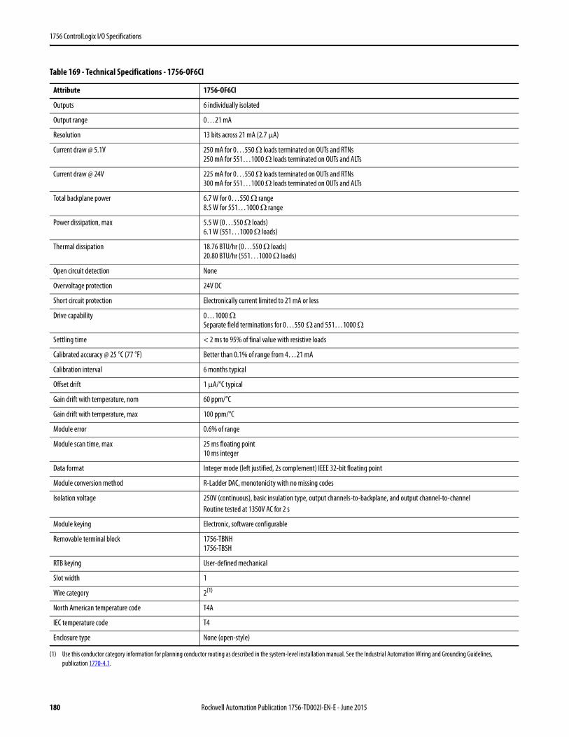
1756 ControlLogix I/O Specifications
Table 169 - Technical Specifications - 1756-OF6CI
Attribute 1756-OF6CI
Outputs 6 individually isolated
Output range 0…21 mA
Resolution 13 bits across 21 mA (2.7 μA)
Current draw @ 5.1V 250 mA for 0…550 Ω loads terminated on OUTs and RTNs250 mA for 551…1000 Ω loads terminated on OUTs and ALTs
Current draw @ 24V 225 mA for 0…550 Ω loads terminated on OUTs and RTNs300 mA for 551…1000 Ω loads terminated on OUTs and ALTs
Total backplane power 6.7 W for 0…550 Ω range8.5 W for 551…1000 Ω range
Power dissipation, max 5.5 W (0…550 Ω loads)6.1 W (551…1000 Ω loads)
Thermal dissipation 18.76 BTU/hr (0…550 Ω loads)20.80 BTU/hr (551…1000 Ω loads)
Open circuit detection None
Overvoltage protection 24V DC
Short circuit protection Electronically current limited to 21 mA or less
Drive capability 0…1000 ΩSeparate field terminations for 0…550 Ω and 551…1000 Ω
Settling time < 2 ms to 95% of final value with resistive loads
Calibrated accuracy @ 25 °C (77 °F) Better than 0.1% of range from 4…21 mA
Calibration interval 6 months typical
Offset drift 1 μA/°C typical
Gain drift with temperature, nom 60 ppm/°C
Gain drift with temperature, max 100 ppm/°C
Module error 0.6% of range
Module scan time, max 25 ms floating point10 ms integer
Data format Integer mode (left justified, 2s complement) IEEE 32-bit floating point
Module conversion method R-Ladder DAC, monotonicity with no missing codes
Isolation voltage 250V (continuous), basic insulation type, output channels-to-backplane, and output channel-to-channelRoutine tested at 1350V AC for 2 s
Module keying Electronic, software configurable
Removable terminal block 1756-TBNH1756-TBSH
RTB keying User-defined mechanical
Slot width 1
Wire category 2(1)
(1) Use this conductor category information for planning conductor routing as described in the system-level installation manual. See the Industrial Automation Wiring and Grounding Guidelines, publication 1770-4.1.
North American temperature code T4A
IEC temperature code T4
Enclosure type None (open-style)
180 Rockwell Automation Publication 1756-TD002I-EN-E - June 2015

1756 ControlLogix I/O Specifications
Table 170 - Environmental Specifications - 1756-OF6CI
Attribute 1756-OF6CI
Temperature, operatingIEC 60068-2-1 (Test Ad, Operating Cold),IEC 60068-2-2 (Test Bd, Operating Dry Heat),IEC 60068-2-14 (Test Nb, Operating Thermal Shock)
0…60 °C (32…140 °F)
Temperature, surrounding air, max 60 °C (140 °F)
Temperature, nonoperatingIEC 60068-2-1 (Test Ab, Unpackaged Nonoperating Cold),IEC 60068-2-2 (Test Bb, Unpackaged Nonoperating Dry Heat),IEC 60068-2-14 (Test Na, Unpackaged Nonoperating Thermal Shock)
-40…85 °C (-40…185 °F)
Relative humidityIEC 60068-2-30 (Test Db, Unpackaged Damp Heat)
5…95% noncondensing
VibrationIEC 60068-2-6 (Test Fc, Operating)
2 g @ 10…500 Hz
Shock, operatingIEC 60068-2-27 (Test Ea, Unpackaged Shock)
30 g
Shock, nonoperatingIEC 60068-2-27 (Test Ea, Unpackaged Shock)
50 g
Emissions CISPR 11, Class A
ESD immunityIEC 61000-4-2
6 kV contact discharges8 kV air discharges
Radiated RF immunityIEC 61000-4-3
10V/m with 1 kHz sine-wave 80% AM from 80… 2000 MHz10V/m with 200 Hz 50% Pulse 100% AM @ 900 MHz10V/m with 200 Hz 50% Pulse 100% AM @ 1890 MHz3V/m with 1 kHz sine-wave 80% AM from 2000…2700 MHz
EFT/B immunityIEC 61000-4-4
±2 kV at 5 kHz on shielded signal ports
Surge transient immunityIEC 61000-4-5
±2 kV line-earth (CM) on shielded signal ports
Conducted RF immunityIEC 61000-4-6
10V rms with 1 kHz sine-wave 80% AM from 150 kHz…80 MHz on shielded signal ports
Rockwell Automation Publication 1756-TD002I-EN-E - June 2015 181

1756 ControlLogix I/O Specifications
Table 171 - Certifications - 1756-OF6CI
Certification(1) 1756-OF6CI
UL UL Listed Industrial Control Equipment. See UL File E65584.
CSA CSA Certified Process Control Equipment. See CSA File LR54689C.CSA Certified Process Control Equipment for Class I, Division 2 Group A,B,C,D Hazardous Locations. See CSA File LR69960C.
CE European Union 2004/108/IEC EMC Directive, compliant with:• EN 61326-1; Meas./Control/Lab., Industrial Requirements• EN 61000-6-2; Industrial Immunity• EN 61000-6-4; Industrial Emissions• EN 61131-2; Programmable Controllers (Clause 8, Zone A & B)European Union 2006/95/EC LVD, compliant with:EN 61131-2; Programmable Controllers (Clause 11)
C-Tick Australian Radiocommunications Act, compliant with:AS/NZS CISPR 11; Industrial Emissions
Ex European Union 94/9/EC ATEX Directive, compliant with:• EN 60079-15; Potentially Explosive Atmospheres, Protection "n"• EN 60079-0; General Requirements II 3 G Ex nA IIC T4 X Gc
FM FM Approved Equipment for use in Class I Division 2 Group A,B,C,D Hazardous Locations
KC Korean Registration of Broadcasting and Communications Equipment, compliant with:Article 58-2 of Radio Waves Act, Clause 3
(1) When marked. See the Product Certification link at http://www.ab.com for Declarations of Conformity, Certificates, and other certification details.
182 Rockwell Automation Publication 1756-TD002I-EN-E - June 2015
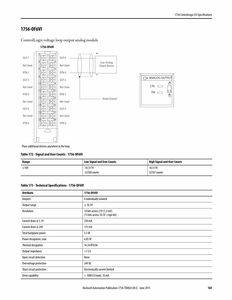
1756 ControlLogix I/O Specifications
1756-OF6VI
ControlLogix voltage loop output analog module
Table 172 - Signal and User Counts - 1756-OF6VI
Range Low Signal and User Counts High Signal and User Counts
±10V -10.517V-32768 counts
10.517V32767 counts
Table 173 - Technical Specifications - 1756-OF6VI
Attribute 1756-OF6VI
Outputs 6 individually isolated
Output range ± 10.5V
Resolution 14 bits across 21V (1.3 mV)(13 bits across 10.5V +sign bit)
Current draw @ 5.1V 250 mA
Current draw @ 24V 175 mA
Total backplane power 5.5 W
Power dissipation, max 4.85 W
Thermal dissipation 16.54 BTU/hr
Output impedance <1 Ω
Open circuit detection None
Overvoltage protection 24V DC
Short circuit protection Electronically current limited
Drive capability > 1000 Ω loads, 10 mA
12
34
56
78
910
1112
1314
1516
1718
1920
+
–
Shield Ground
OUT-1
Not Used
RTN-1
OUT-3
RTN-3
Not Used
OUT-5
Not Used
Not Used
RTN-5
OUT-0
Not Used
RTN-0
OUT-2
RTN-2
Not Used
OUT-4
Not Used
Not Used
RTN-4
User Analog Output Device
Place additional devices anywhere in the loop.
ANALOG OUTPUT
CAL
OK
1756-OF6VI
Rockwell Automation Publication 1756-TD002I-EN-E - June 2015 183
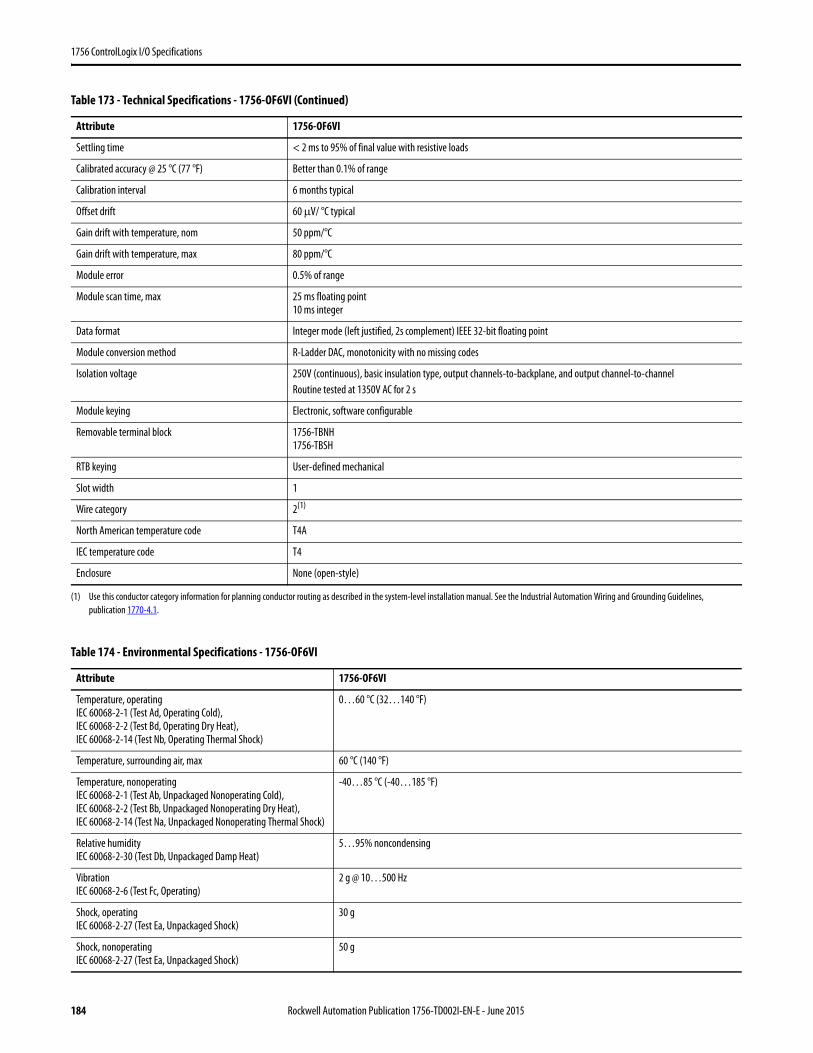
1756 ControlLogix I/O Specifications
Settling time < 2 ms to 95% of final value with resistive loads
Calibrated accuracy @ 25 °C (77 °F) Better than 0.1% of range
Calibration interval 6 months typical
Offset drift 60 μV/ °C typical
Gain drift with temperature, nom 50 ppm/°C
Gain drift with temperature, max 80 ppm/°C
Module error 0.5% of range
Module scan time, max 25 ms floating point10 ms integer
Data format Integer mode (left justified, 2s complement) IEEE 32-bit floating point
Module conversion method R-Ladder DAC, monotonicity with no missing codes
Isolation voltage 250V (continuous), basic insulation type, output channels-to-backplane, and output channel-to-channelRoutine tested at 1350V AC for 2 s
Module keying Electronic, software configurable
Removable terminal block 1756-TBNH1756-TBSH
RTB keying User-defined mechanical
Slot width 1
Wire category 2(1)
North American temperature code T4A
IEC temperature code T4
Enclosure None (open-style)
(1) Use this conductor category information for planning conductor routing as described in the system-level installation manual. See the Industrial Automation Wiring and Grounding Guidelines, publication 1770-4.1.
Table 174 - Environmental Specifications - 1756-OF6VI
Attribute 1756-OF6VI
Temperature, operatingIEC 60068-2-1 (Test Ad, Operating Cold),IEC 60068-2-2 (Test Bd, Operating Dry Heat),IEC 60068-2-14 (Test Nb, Operating Thermal Shock)
0…60 °C (32…140 °F)
Temperature, surrounding air, max 60 °C (140 °F)
Temperature, nonoperatingIEC 60068-2-1 (Test Ab, Unpackaged Nonoperating Cold),IEC 60068-2-2 (Test Bb, Unpackaged Nonoperating Dry Heat),IEC 60068-2-14 (Test Na, Unpackaged Nonoperating Thermal Shock)
-40…85 °C (-40…185 °F)
Relative humidityIEC 60068-2-30 (Test Db, Unpackaged Damp Heat)
5…95% noncondensing
VibrationIEC 60068-2-6 (Test Fc, Operating)
2 g @ 10…500 Hz
Shock, operatingIEC 60068-2-27 (Test Ea, Unpackaged Shock)
30 g
Shock, nonoperatingIEC 60068-2-27 (Test Ea, Unpackaged Shock)
50 g
Table 173 - Technical Specifications - 1756-OF6VI (Continued)
Attribute 1756-OF6VI
184 Rockwell Automation Publication 1756-TD002I-EN-E - June 2015

1756 ControlLogix I/O Specifications
Emissions CISPR 11, Class A
ESD immunityIEC 61000-4-2
6 kV contact discharges8 kV air discharges
Radiated RF immunityIEC 61000-4-3
10V/m with 1 kHz sine-wave 80% AM from 80… 2000 MHz10V/m with 200 Hz 50% Pulse 100% AM @ 900 MHz10V/m with 200 Hz 50% Pulse 100% AM @ 1890 MHz3V/m with 1 kHz sine-wave 80% AM from 2000…2700 MHz
EFT/B immunityIEC 61000-4-4
±2 kV at 5 kHz on shielded signal ports
Surge transient immunityIEC 61000-4-5
±2 kV line-earth (CM) on shielded signal ports
Conducted RF ImmunityIEC 61000-4-6
10V rms with 1 kHz sine-wave 80% AM from 150 kHz…80 MHz on shielded signal ports
Table 175 - Certifications - 1756-OF6VI
Certification(1)
(1) When marked. See the Product Certification link at http://www.ab.com for Declarations of Conformity, Certificates, and other certification details.
1756-OF6VI
UL UL Listed Industrial Control Equipment. See UL File E65584.
CSA CSA Certified Process Control Equipment. See CSA File LR54689C.CSA Certified Process Control Equipment for Class I, Division 2 Group A,B,C,D Hazardous Locations. See CSA File LR69960C.
CE European Union 2004/108/IEC EMC Directive, compliant with:• EN 61326-1; Meas./Control/Lab., Industrial Requirements• EN 61000-6-2; Industrial Immunity• EN 61000-6-4; Industrial Emissions• EN 61131-2; Programmable Controllers (Clause 8, Zone A & B)European Union 2006/95/EC LVD, compliant with:EN 61131-2; Programmable Controllers (Clause 11)
C-Tick Australian Radiocommunications Act, compliant with:AS/NZS CISPR 11; Industrial Emissions
Ex European Union 94/9/EC ATEX Directive, compliant with:• EN 60079-15; Potentially Explosive Atmospheres, Protection "n"• EN 60079-0; General Requirements II 3 G Ex nA IIC T4 X Gc
FM FM Approved Equipment for use in Class I Division 2 Group A,B,C,D Hazardous Locations
KC Korean Registration of Broadcasting and Communications Equipment, compliant with:Article 58-2 of Radio Waves Act, Clause 3
Table 174 - Environmental Specifications - 1756-OF6VI (Continued)
Attribute 1756-OF6VI
Rockwell Automation Publication 1756-TD002I-EN-E - June 2015 185
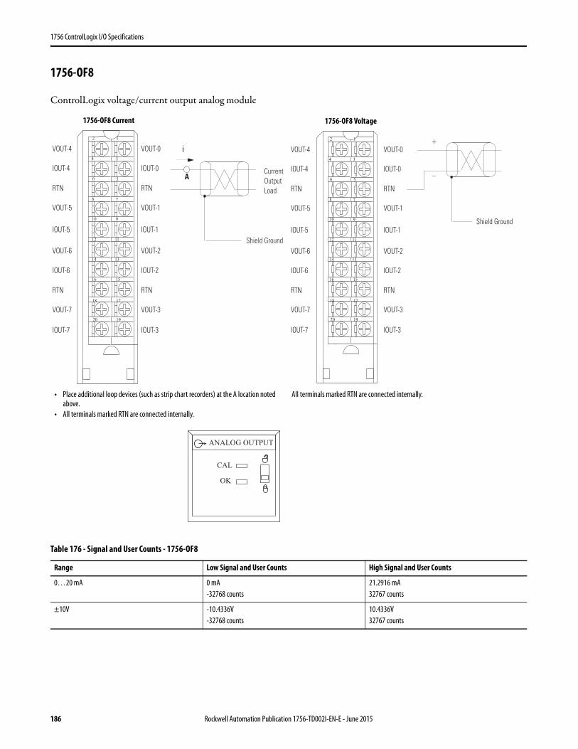
1756 ControlLogix I/O Specifications
1756-OF8
ControlLogix voltage/current output analog module
Table 176 - Signal and User Counts - 1756-OF8
Range Low Signal and User Counts High Signal and User Counts
0…20 mA 0 mA-32768 counts
21.2916 mA32767 counts
±10V -10.4336V-32768 counts
10.4336V32767 counts
12
34
56
78
910
1112
1314
1516
1718
1920
Shield Ground
i
Current OutputLoad
VOUT-4
IOUT-4
RTN
VOUT-5
VOUT-6
IOUT-6
RTN
VOUT-7
IOUT-5
IOUT-7
VOUT-0
IOUT-0
RTN
VOUT-1
VOUT-2
IOUT-2
RTN
VOUT-3
IOUT-1
IOUT-3
A
12
34
56
78
910
1112
1314
1516
1718
1920
+
–
Shield Ground
VOUT-4
IOUT-4
RTN
VOUT-5
VOUT-6
IOUT-6
RTN
VOUT-7
IOUT-5
IOUT-7
VOUT-0
IOUT-0
RTN
VOUT-1
VOUT-2
IOUT-2
RTN
VOUT-3
IOUT-1
IOUT-3
• Place additional loop devices (such as strip chart recorders) at the A location noted above.
• All terminals marked RTN are connected internally.
All terminals marked RTN are connected internally.
ANALOG OUTPUT
CAL
OK
1756-OF8 Current 1756-OF8 Voltage
186 Rockwell Automation Publication 1756-TD002I-EN-E - June 2015
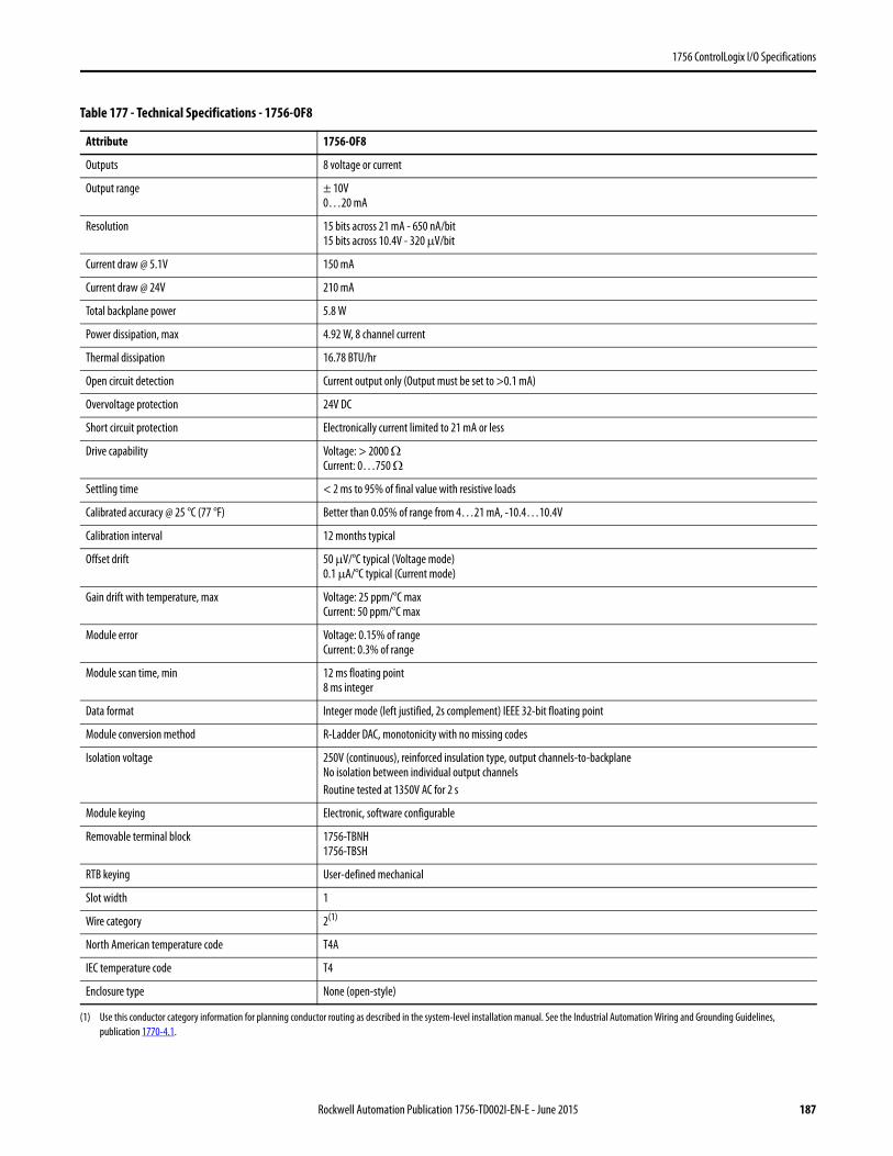
1756 ControlLogix I/O Specifications
Table 177 - Technical Specifications - 1756-OF8
Attribute 1756-OF8
Outputs 8 voltage or current
Output range ± 10V0…20 mA
Resolution 15 bits across 21 mA - 650 nA/bit15 bits across 10.4V - 320 μV/bit
Current draw @ 5.1V 150 mA
Current draw @ 24V 210 mA
Total backplane power 5.8 W
Power dissipation, max 4.92 W, 8 channel current
Thermal dissipation 16.78 BTU/hr
Open circuit detection Current output only (Output must be set to >0.1 mA)
Overvoltage protection 24V DC
Short circuit protection Electronically current limited to 21 mA or less
Drive capability Voltage: > 2000 Ω Current: 0…750 Ω
Settling time < 2 ms to 95% of final value with resistive loads
Calibrated accuracy @ 25 °C (77 °F) Better than 0.05% of range from 4…21 mA, -10.4…10.4V
Calibration interval 12 months typical
Offset drift 50 μV/°C typical (Voltage mode)0.1 μA/°C typical (Current mode)
Gain drift with temperature, max Voltage: 25 ppm/°C maxCurrent: 50 ppm/°C max
Module error Voltage: 0.15% of rangeCurrent: 0.3% of range
Module scan time, min 12 ms floating point8 ms integer
Data format Integer mode (left justified, 2s complement) IEEE 32-bit floating point
Module conversion method R-Ladder DAC, monotonicity with no missing codes
Isolation voltage 250V (continuous), reinforced insulation type, output channels-to-backplaneNo isolation between individual output channelsRoutine tested at 1350V AC for 2 s
Module keying Electronic, software configurable
Removable terminal block 1756-TBNH1756-TBSH
RTB keying User-defined mechanical
Slot width 1
Wire category 2(1)
(1) Use this conductor category information for planning conductor routing as described in the system-level installation manual. See the Industrial Automation Wiring and Grounding Guidelines, publication 1770-4.1.
North American temperature code T4A
IEC temperature code T4
Enclosure type None (open-style)
Rockwell Automation Publication 1756-TD002I-EN-E - June 2015 187

1756 ControlLogix I/O Specifications
Table 178 - Environmental Specifications - 1756-OF8
Attribute 1756-OF8
Temperature, operatingIEC 60068-2-1 (Test Ad, Operating Cold),IEC 60068-2-2 (Test Bd, Operating Dry Heat),IEC 60068-2-14 (Test Nb, Operating Thermal Shock)
0…60 °C (32…140 °F)
Temperature, surrounding air, max 60 °C (140 °F)
Temperature, nonoperatingIEC 60068-2-1 (Test Ab, Unpackaged Nonoperating Cold),IEC 60068-2-2 (Test Bb, Unpackaged Nonoperating Dry Heat),IEC 60068-2-14 (Test Na, Unpackaged Nonoperating Thermal Shock)
-40…85 °C (-40…185 °F)
Relative humidityIEC 60068-2-30 (Test Db, Unpackaged Damp Heat)
5…95% noncondensing
VibrationIEC 60068-2-6 (Test Fc, Operating)
2 g @ 10…500 Hz
Shock, operatingIEC 60068-2-27 (Test Ea, Unpackaged Shock)
30 g
Shock, nonoperatingIEC 60068-2-27 (Test Ea, Unpackaged Shock)
50 g
Emissions CISPR 11, Class A
ESD immunityIEC 61000-4-2
6 kV contact discharges8 kV air discharges
Radiated RF immunityIEC 61000-4-3
10V/m with 1 kHz sine-wave 80% AM from 80… 2000 MHz10V/m with 200 Hz 50% Pulse 100% AM @ 900 MHz10V/m with 200 Hz 50% Pulse 100% AM @ 1890 MHz3V/m with 1 kHz sine-wave 80% AM from 2000…2700 MHz
EFT/B immunityIEC 61000-4-4
±2 kV at 5 kHz on shielded signal ports
Surge transient immunityIEC 61000-4-5
±2 kV line-earth (CM) on shielded signal ports
Conducted RF immunityIEC 61000-4-6
10V rms with 1 kHz sine-wave 80% AM from 150 kHz…80 MHz on shielded signal ports
188 Rockwell Automation Publication 1756-TD002I-EN-E - June 2015

1756 ControlLogix I/O Specifications
Table 179 - Certifications - 1756-OF8
Certification(1) 1756-OF8
UL UL Listed Industrial Control Equipment. See UL File E65584.
CSA CSA Certified Process Control Equipment. See CSA File LR54689C.CSA Certified Process Control Equipment for Class I, Division 2 Group A,B,C,D Hazardous Locations. See CSA File LR69960C.
CE European Union 2004/108/IEC EMC Directive, compliant with:• EN 61326-1; Meas./Control/Lab., Industrial Requirements• EN 61000-6-2; Industrial Immunity• EN 61000-6-4; Industrial Emissions• EN 61131-2; Programmable Controllers (Clause 8, Zone A & B)European Union 2006/95/EC LVD, compliant with:EN 61131-2; Programmable Controllers (Clause 11)
C-Tick Australian Radiocommunications Act, compliant with:AS/NZS CISPR 11; Industrial Emissions
Ex European Union 94/9/EC ATEX Directive, compliant with:• EN 60079-15; Potentially Explosive Atmospheres, Protection "n"• EN 60079-0; General Requirements II 3 G Ex nA IIC T4 X Gc
FM FM Approved Equipment for use in Class I Division 2 Group A,B,C,D Hazardous Locations
KC Korean Registration of Broadcasting and Communications Equipment, compliant with:Article 58-2 of Radio Waves Act, Clause 3
(1) When marked. See the Product Certification link at http://www.ab.com for Declarations of Conformity, Certificates, and other certification details.
Rockwell Automation Publication 1756-TD002I-EN-E - June 2015 189
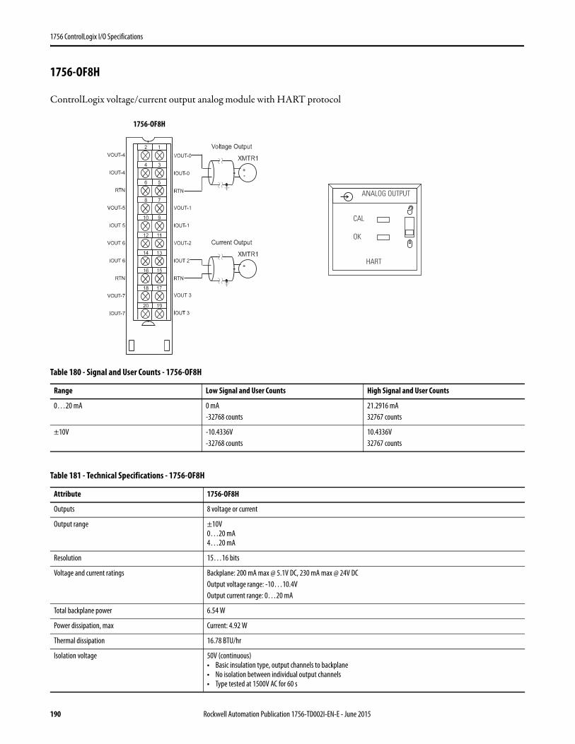
1756 ControlLogix I/O Specifications
1756-OF8H
ControlLogix voltage/current output analog module with HART protocol
Table 180 - Signal and User Counts - 1756-OF8H
Range Low Signal and User Counts High Signal and User Counts
0…20 mA 0 mA-32768 counts
21.2916 mA32767 counts
±10V -10.4336V-32768 counts
10.4336V32767 counts
Table 181 - Technical Specifications - 1756-OF8H
Attribute 1756-OF8H
Outputs 8 voltage or current
Output range ±10V0…20 mA4…20 mA
Resolution 15…16 bits
Voltage and current ratings Backplane: 200 mA max @ 5.1V DC, 230 mA max @ 24V DCOutput voltage range: -10…10.4VOutput current range: 0…20 mA
Total backplane power 6.54 W
Power dissipation, max Current: 4.92 W
Thermal dissipation 16.78 BTU/hr
Isolation voltage 50V (continuous)• Basic insulation type, output channels to backplane• No isolation between individual output channels• Type tested at 1500V AC for 60 s
ANALOG OUTPUT
CAL
OK
HART
1756-OF8H
190 Rockwell Automation Publication 1756-TD002I-EN-E - June 2015
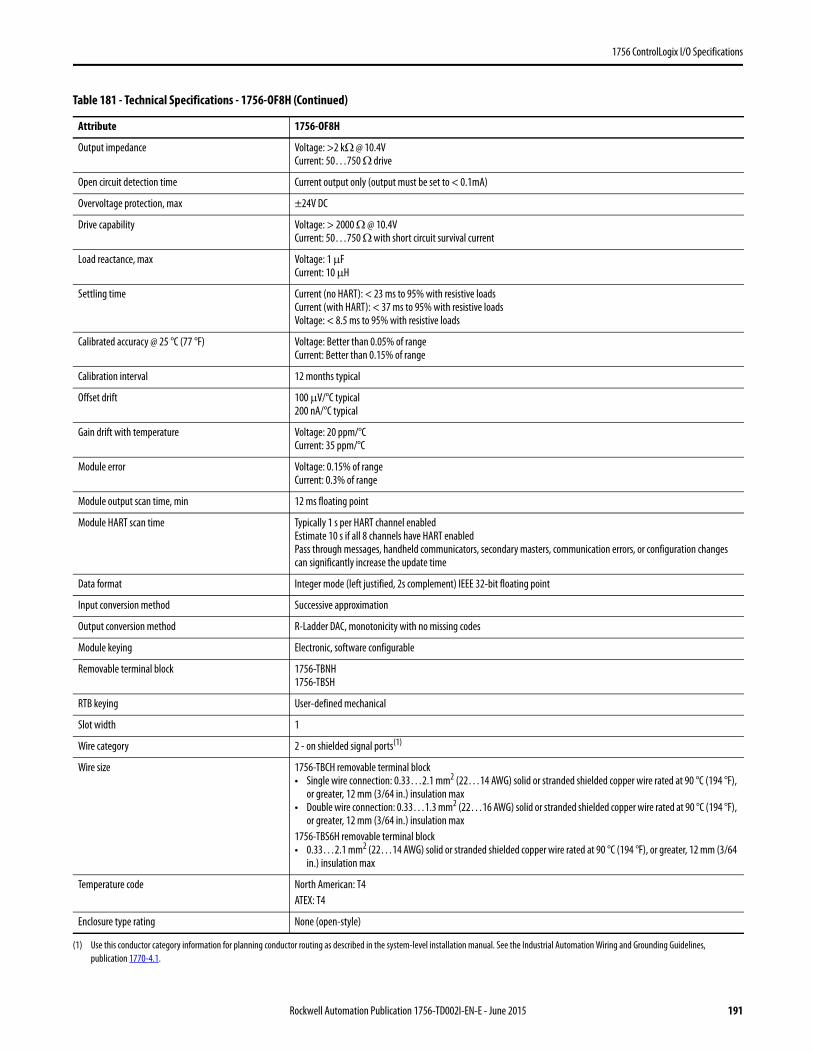
1756 ControlLogix I/O Specifications
Output impedance Voltage: >2 kΩ @ 10.4VCurrent: 50…750 Ω drive
Open circuit detection time Current output only (output must be set to < 0.1mA)
Overvoltage protection, max ±24V DC
Drive capability Voltage: > 2000 Ω @ 10.4VCurrent: 50…750 Ω with short circuit survival current
Load reactance, max Voltage: 1 μFCurrent: 10 μH
Settling time Current (no HART): < 23 ms to 95% with resistive loadsCurrent (with HART): < 37 ms to 95% with resistive loadsVoltage: < 8.5 ms to 95% with resistive loads
Calibrated accuracy @ 25 °C (77 °F) Voltage: Better than 0.05% of rangeCurrent: Better than 0.15% of range
Calibration interval 12 months typical
Offset drift 100 μV/°C typical200 nA/°C typical
Gain drift with temperature Voltage: 20 ppm/°CCurrent: 35 ppm/°C
Module error Voltage: 0.15% of rangeCurrent: 0.3% of range
Module output scan time, min 12 ms floating point
Module HART scan time Typically 1 s per HART channel enabledEstimate 10 s if all 8 channels have HART enabledPass through messages, handheld communicators, secondary masters, communication errors, or configuration changes can significantly increase the update time
Data format Integer mode (left justified, 2s complement) IEEE 32-bit floating point
Input conversion method Successive approximation
Output conversion method R-Ladder DAC, monotonicity with no missing codes
Module keying Electronic, software configurable
Removable terminal block 1756-TBNH1756-TBSH
RTB keying User-defined mechanical
Slot width 1
Wire category 2 - on shielded signal ports(1)
Wire size 1756-TBCH removable terminal block• Single wire connection: 0.33…2.1 mm2 (22…14 AWG) solid or stranded shielded copper wire rated at 90 °C (194 °F),
or greater, 12 mm (3/64 in.) insulation max• Double wire connection: 0.33…1.3 mm2 (22…16 AWG) solid or stranded shielded copper wire rated at 90 °C (194 °F),
or greater, 12 mm (3/64 in.) insulation max1756-TBS6H removable terminal block• 0.33…2.1 mm2 (22…14 AWG) solid or stranded shielded copper wire rated at 90 °C (194 °F), or greater, 12 mm (3/64
in.) insulation max
Temperature code North American: T4ATEX: T4
Enclosure type rating None (open-style)
(1) Use this conductor category information for planning conductor routing as described in the system-level installation manual. See the Industrial Automation Wiring and Grounding Guidelines, publication 1770-4.1.
Table 181 - Technical Specifications - 1756-OF8H (Continued)
Attribute 1756-OF8H
Rockwell Automation Publication 1756-TD002I-EN-E - June 2015 191
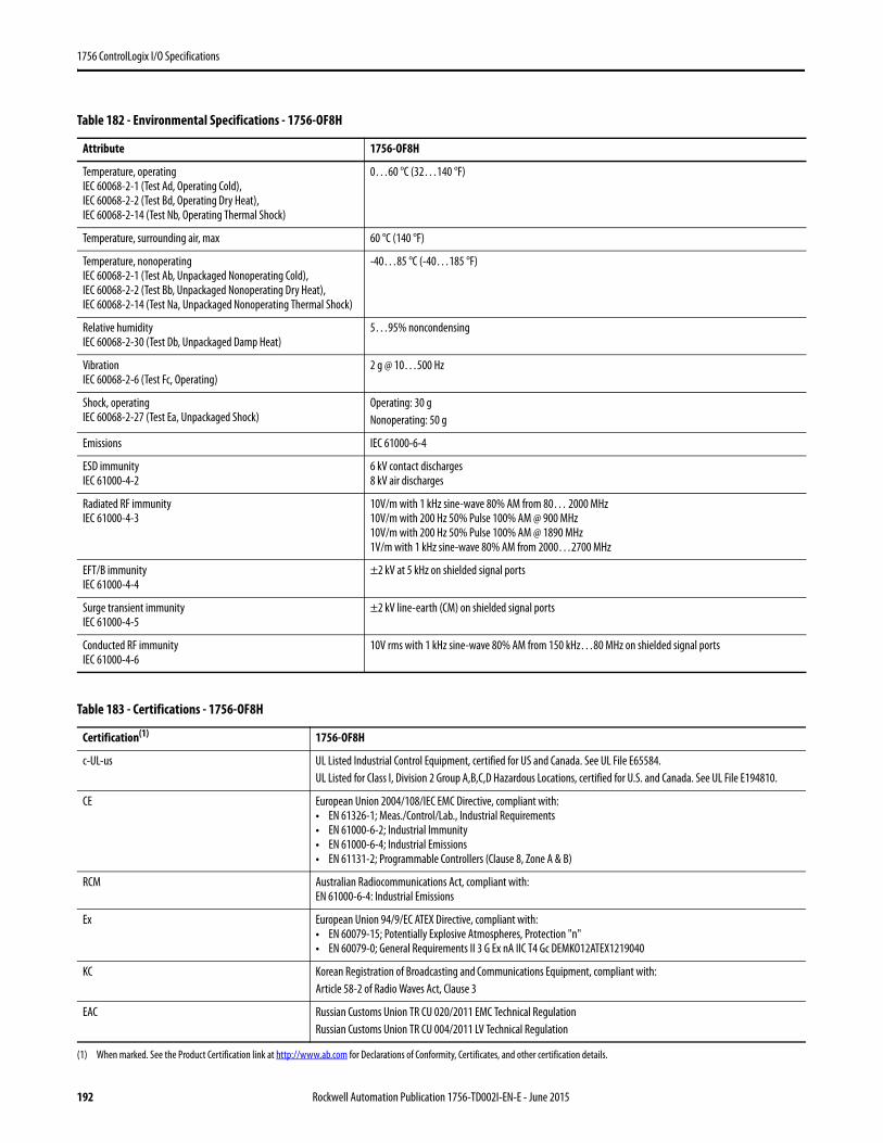
1756 ControlLogix I/O Specifications
Table 182 - Environmental Specifications - 1756-OF8H
Attribute 1756-OF8H
Temperature, operatingIEC 60068-2-1 (Test Ad, Operating Cold),IEC 60068-2-2 (Test Bd, Operating Dry Heat),IEC 60068-2-14 (Test Nb, Operating Thermal Shock)
0…60 °C (32…140 °F)
Temperature, surrounding air, max 60 °C (140 °F)
Temperature, nonoperatingIEC 60068-2-1 (Test Ab, Unpackaged Nonoperating Cold),IEC 60068-2-2 (Test Bb, Unpackaged Nonoperating Dry Heat),IEC 60068-2-14 (Test Na, Unpackaged Nonoperating Thermal Shock)
-40…85 °C (-40…185 °F)
Relative humidityIEC 60068-2-30 (Test Db, Unpackaged Damp Heat)
5…95% noncondensing
VibrationIEC 60068-2-6 (Test Fc, Operating)
2 g @ 10…500 Hz
Shock, operatingIEC 60068-2-27 (Test Ea, Unpackaged Shock)
Operating: 30 g Nonoperating: 50 g
Emissions IEC 61000-6-4
ESD immunityIEC 61000-4-2
6 kV contact discharges8 kV air discharges
Radiated RF immunityIEC 61000-4-3
10V/m with 1 kHz sine-wave 80% AM from 80… 2000 MHz10V/m with 200 Hz 50% Pulse 100% AM @ 900 MHz10V/m with 200 Hz 50% Pulse 100% AM @ 1890 MHz1V/m with 1 kHz sine-wave 80% AM from 2000…2700 MHz
EFT/B immunityIEC 61000-4-4
±2 kV at 5 kHz on shielded signal ports
Surge transient immunityIEC 61000-4-5
±2 kV line-earth (CM) on shielded signal ports
Conducted RF immunityIEC 61000-4-6
10V rms with 1 kHz sine-wave 80% AM from 150 kHz…80 MHz on shielded signal ports
Table 183 - Certifications - 1756-OF8H
Certification(1)
(1) When marked. See the Product Certification link at http://www.ab.com for Declarations of Conformity, Certificates, and other certification details.
1756-OF8H
c-UL-us UL Listed Industrial Control Equipment, certified for US and Canada. See UL File E65584.UL Listed for Class I, Division 2 Group A,B,C,D Hazardous Locations, certified for U.S. and Canada. See UL File E194810.
CE European Union 2004/108/IEC EMC Directive, compliant with:• EN 61326-1; Meas./Control/Lab., Industrial Requirements• EN 61000-6-2; Industrial Immunity• EN 61000-6-4; Industrial Emissions• EN 61131-2; Programmable Controllers (Clause 8, Zone A & B)
RCM Australian Radiocommunications Act, compliant with:EN 61000-6-4: Industrial Emissions
Ex European Union 94/9/EC ATEX Directive, compliant with:• EN 60079-15; Potentially Explosive Atmospheres, Protection "n"• EN 60079-0; General Requirements II 3 G Ex nA IIC T4 Gc DEMKO12ATEX1219040
KC Korean Registration of Broadcasting and Communications Equipment, compliant with:Article 58-2 of Radio Waves Act, Clause 3
EAC Russian Customs Union TR CU 020/2011 EMC Technical RegulationRussian Customs Union TR CU 004/2011 LV Technical Regulation
192 Rockwell Automation Publication 1756-TD002I-EN-E - June 2015
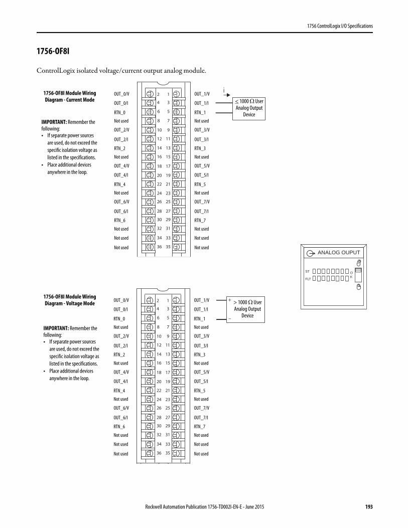
1756 ControlLogix I/O Specifications
1756-OF8I
ControlLogix isolated voltage/current output analog module.
ANALOG OUPUT
ST
FLT
OK
1
3
5
7
01 9
1112
41 31
61 51
81 71
02 91
22 12
42 32
62 52
82 72
03 92
23 13
33
63 53
2
34
8
6
4
+
–
1
3
5
7
01 9
1112
41 31
61 51
81 71
02 91
22 12
42 32
62 52
82 72
03 92
23 13
33
63 53
2
34
8
6
4
iOUT_0/V
OUT_0/I
RTN_0
Not used
OUT_2/V
OUT_2/I
RTN_2
Not used
< 1000 Ω User Analog Output
Device
OUT_4/V
OUT_4/I
RTN_4
Not used
OUT_6/V
OUT_6/I
RTN_6
Not used
Not used
Not used
OUT_1/V
OUT_1/I
RTN_1
Not used
OUT_3/V
OUT_3/I
RTN_3
Not used
OUT_5/V
OUT_5/I
RTN_5
Not used
OUT_7/V
OUT_7/I
RTN_7
Not used
Not used
Not used
IMPORTANT: Remember the following:• If separate power sources
are used, do not exceed the specific isolation voltage as listed in the specifications.
• Place additional devices anywhere in the loop.
1756-OF8I Module Wiring Diagram - Current Mode
OUT_0/V
OUT_0/I
RTN_0
Not used
OUT_2/V
OUT_2/I
RTN_2
Not used
> 1000 Ω User Analog Output
Device
OUT_4/V
OUT_4/I
RTN_4
Not used
OUT_6/V
OUT_6/I
RTN_6
Not used
Not used
Not used
OUT_1/V
OUT_1/I
RTN_1
Not used
OUT_3/V
OUT_3/I
RTN_3
Not used
OUT_5/V
OUT_5/I
RTN_5
Not used
OUT_7/V
OUT_7/I
RTN_7
Not used
Not used
Not used
1756-OF8I Module Wiring Diagram - Voltage Mode
IMPORTANT: Remember the following:• If separate power sources
are used, do not exceed the specific isolation voltage as listed in the specifications.
• Place additional devices anywhere in the loop.
Rockwell Automation Publication 1756-TD002I-EN-E - June 2015 193
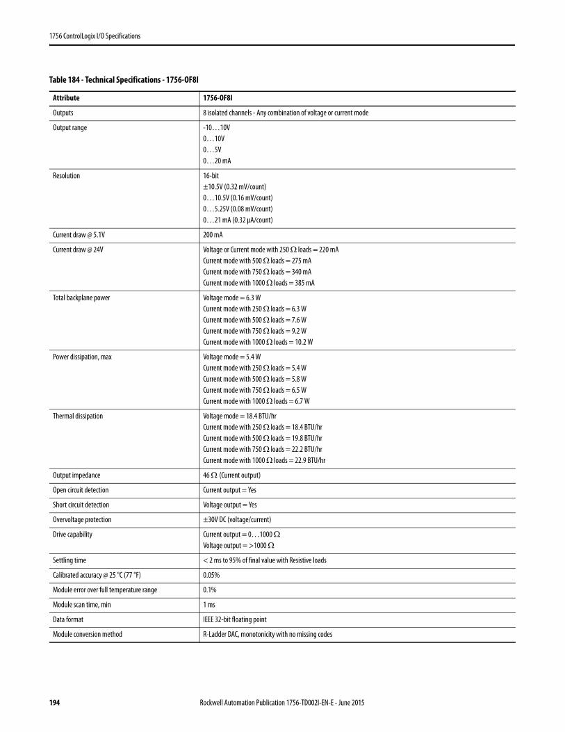
1756 ControlLogix I/O Specifications
Table 184 - Technical Specifications - 1756-OF8I
Attribute 1756-OF8I
Outputs 8 isolated channels - Any combination of voltage or current mode
Output range -10…10V0…10V0…5V0…20 mA
Resolution 16-bit±10.5V (0.32 mV/count)0…10.5V (0.16 mV/count)0…5.25V (0.08 mV/count)0…21 mA (0.32 μA/count)
Current draw @ 5.1V 200 mA
Current draw @ 24V Voltage or Current mode with 250 Ω loads = 220 mACurrent mode with 500 Ω loads = 275 mACurrent mode with 750 Ω loads = 340 mACurrent mode with 1000 Ω loads = 385 mA
Total backplane power Voltage mode = 6.3 WCurrent mode with 250 Ω loads = 6.3 WCurrent mode with 500 Ω loads = 7.6 WCurrent mode with 750 Ω loads = 9.2 WCurrent mode with 1000 Ω loads = 10.2 W
Power dissipation, max Voltage mode = 5.4 WCurrent mode with 250 Ω loads = 5.4 WCurrent mode with 500 Ω loads = 5.8 WCurrent mode with 750 Ω loads = 6.5 WCurrent mode with 1000 Ω loads = 6.7 W
Thermal dissipation Voltage mode = 18.4 BTU/hrCurrent mode with 250 Ω loads = 18.4 BTU/hrCurrent mode with 500 Ω loads = 19.8 BTU/hrCurrent mode with 750 Ω loads = 22.2 BTU/hrCurrent mode with 1000 Ω loads = 22.9 BTU/hr
Output impedance 46 Ω (Current output)
Open circuit detection Current output = Yes
Short circuit detection Voltage output = Yes
Overvoltage protection ±30V DC (voltage/current)
Drive capability Current output = 0…1000 ΩVoltage output = >1000 Ω
Settling time < 2 ms to 95% of final value with Resistive loads
Calibrated accuracy @ 25 °C (77 °F) 0.05%
Module error over full temperature range 0.1%
Module scan time, min 1 ms
Data format IEEE 32-bit floating point
Module conversion method R-Ladder DAC, monotonicity with no missing codes
194 Rockwell Automation Publication 1756-TD002I-EN-E - June 2015
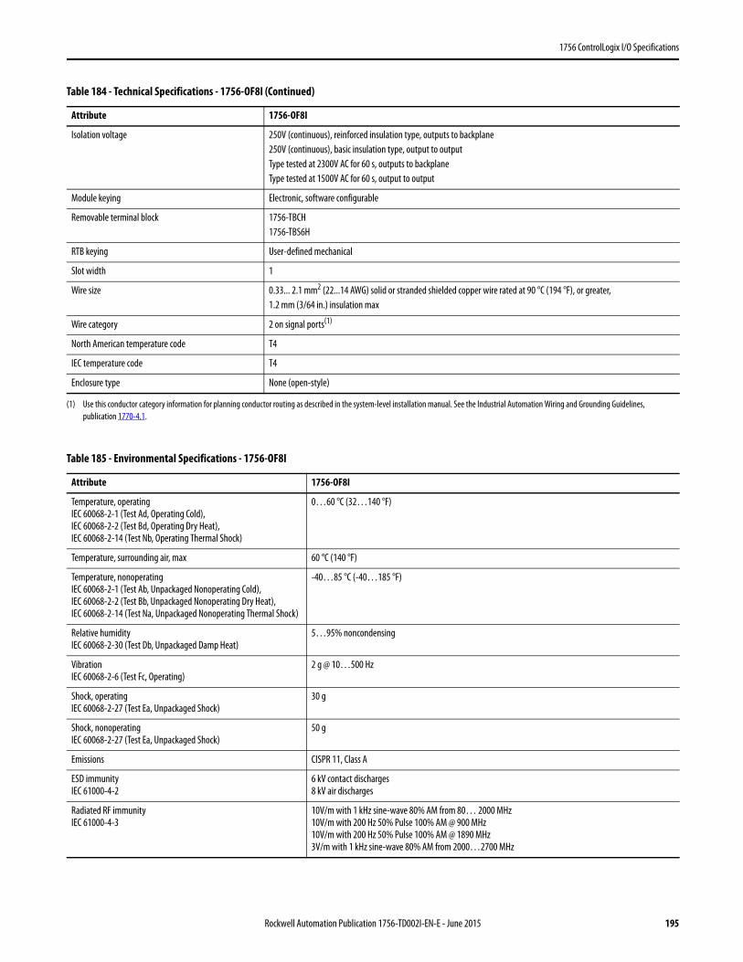
1756 ControlLogix I/O Specifications
Isolation voltage 250V (continuous), reinforced insulation type, outputs to backplane250V (continuous), basic insulation type, output to outputType tested at 2300V AC for 60 s, outputs to backplaneType tested at 1500V AC for 60 s, output to output
Module keying Electronic, software configurable
Removable terminal block 1756-TBCH1756-TBS6H
RTB keying User-defined mechanical
Slot width 1
Wire size 0.33... 2.1 mm2 (22...14 AWG) solid or stranded shielded copper wire rated at 90 °C (194 °F), or greater, 1.2 mm (3/64 in.) insulation max
Wire category 2 on signal ports(1)
North American temperature code T4
IEC temperature code T4
Enclosure type None (open-style)
(1) Use this conductor category information for planning conductor routing as described in the system-level installation manual. See the Industrial Automation Wiring and Grounding Guidelines, publication 1770-4.1.
Table 185 - Environmental Specifications - 1756-OF8I
Attribute 1756-OF8I
Temperature, operatingIEC 60068-2-1 (Test Ad, Operating Cold),IEC 60068-2-2 (Test Bd, Operating Dry Heat),IEC 60068-2-14 (Test Nb, Operating Thermal Shock)
0…60 °C (32…140 °F)
Temperature, surrounding air, max 60 °C (140 °F)
Temperature, nonoperatingIEC 60068-2-1 (Test Ab, Unpackaged Nonoperating Cold),IEC 60068-2-2 (Test Bb, Unpackaged Nonoperating Dry Heat),IEC 60068-2-14 (Test Na, Unpackaged Nonoperating Thermal Shock)
-40…85 °C (-40…185 °F)
Relative humidityIEC 60068-2-30 (Test Db, Unpackaged Damp Heat)
5…95% noncondensing
VibrationIEC 60068-2-6 (Test Fc, Operating)
2 g @ 10…500 Hz
Shock, operatingIEC 60068-2-27 (Test Ea, Unpackaged Shock)
30 g
Shock, nonoperatingIEC 60068-2-27 (Test Ea, Unpackaged Shock)
50 g
Emissions CISPR 11, Class A
ESD immunityIEC 61000-4-2
6 kV contact discharges8 kV air discharges
Radiated RF immunityIEC 61000-4-3
10V/m with 1 kHz sine-wave 80% AM from 80… 2000 MHz10V/m with 200 Hz 50% Pulse 100% AM @ 900 MHz10V/m with 200 Hz 50% Pulse 100% AM @ 1890 MHz3V/m with 1 kHz sine-wave 80% AM from 2000…2700 MHz
Table 184 - Technical Specifications - 1756-OF8I (Continued)
Attribute 1756-OF8I
Rockwell Automation Publication 1756-TD002I-EN-E - June 2015 195
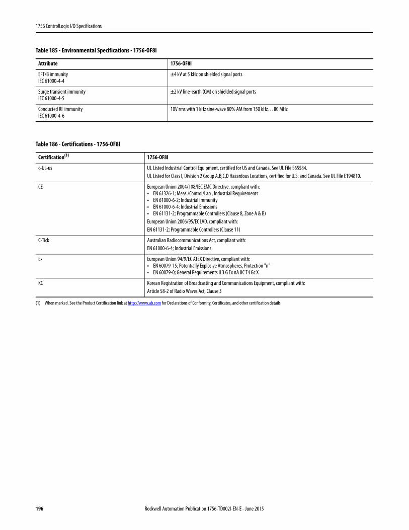
1756 ControlLogix I/O Specifications
EFT/B immunityIEC 61000-4-4
±4 kV at 5 kHz on shielded signal ports
Surge transient immunityIEC 61000-4-5
±2 kV line-earth (CM) on shielded signal ports
Conducted RF immunityIEC 61000-4-6
10V rms with 1 kHz sine-wave 80% AM from 150 kHz…80 MHz
Table 186 - Certifications - 1756-OF8I
Certification(1)
(1) When marked. See the Product Certification link at http://www.ab.com for Declarations of Conformity, Certificates, and other certification details.
1756-OF8I
c-UL-us UL Listed Industrial Control Equipment, certified for US and Canada. See UL File E65584.UL Listed for Class I, Division 2 Group A,B,C,D Hazardous Locations, certified for U.S. and Canada. See UL File E194810.
CE European Union 2004/108/IEC EMC Directive, compliant with:• EN 61326-1; Meas./Control/Lab., Industrial Requirements• EN 61000-6-2; Industrial Immunity• EN 61000-6-4; Industrial Emissions• EN 61131-2; Programmable Controllers (Clause 8, Zone A & B)European Union 2006/95/EC LVD, compliant with:EN 61131-2; Programmable Controllers (Clause 11)
C-Tick Australian Radiocommunications Act, compliant with:EN 61000-6-4; Industrial Emissions
Ex European Union 94/9/EC ATEX Directive, compliant with:• EN 60079-15; Potentially Explosive Atmospheres, Protection "n"• EN 60079-0; General Requirements II 3 G Ex nA IIC T4 Gc X
KC Korean Registration of Broadcasting and Communications Equipment, compliant with:Article 58-2 of Radio Waves Act, Clause 3
Table 185 - Environmental Specifications - 1756-OF8I
Attribute 1756-OF8I
196 Rockwell Automation Publication 1756-TD002I-EN-E - June 2015

1756 ControlLogix I/O Specifications
1756-OF8IH
ControlLogix isolated HART current analog output module
Table 187 - Signal and User Counts - 1756-OF8IH
Range Low Signal High Signal
0…21 mA 0 mA 21.2916 mA
Table 188 - Technical Specifications - 1756-OF8IH
Attribute 1756-OF8IH
Outputs 8 current
Output range 0…20 mA4…20 mA
Resolution 15 bits across 24 mA, 732 nA per bit
Voltage and current ratings Backplane: 220 mA @ 5.1V DC, 360 mA @ 24V DCOutput current: 0…20 mA and 4…20 mAOutput Voltage: 5…30V DC
Current draw @ 24V 400 mA (estimated)
Power dissipation, max 6.5 W nom(< 6.4 W with 50 Ω resistance load on all channels, <6.5 W with 250 Ω resistance load on all channels, <6.7 W with 750 Ω resistance load on all channels)
Open circuit detection Current output only (output must be set >= 0.1 mA)
Overvoltage protection, max ±24V DC
Output short circuit protection Current electronically limited to <= 21 mA with no damage
Drive capability 50…750 Ω with short circuit survival
Load reactance, max 10 μH
Rockwell Automation Publication 1756-TD002I-EN-E - June 2015 197
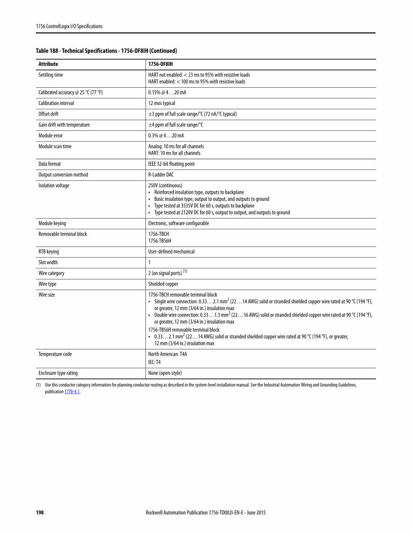
1756 ControlLogix I/O Specifications
Settling time HART not enabled: < 23 ms to 95% with resistive loadsHART enabled: < 100 ms to 95% with resistive loads
Calibrated accuracy @ 25 °C (77 °F) 0.15% @ 4…20 mA
Calibration interval 12 mos typical
Offset drift ±3 ppm of full scale range/°C (72 nA/°C typical)
Gain drift with temperature ±4 ppm of full scale range/°C
Module error 0.3% @ 4…20 mA
Module scan time Analog: 10 ms for all channelsHART: 10 ms for all channels
Data format IEEE 32-bit floating point
Output conversion method R-Ladder DAC
Isolation voltage 250V (continuous)• Reinforced insulation type, outputs to backplane• Basic insulation type, output to output, and outputs to ground• Type tested at 3535V DC for 60 s, outputs to backplane• Type tested at 2120V DC for 60 s, output to output, and outputs to ground
Module keying Electronic, software configurable
Removable terminal block 1756-TBCH1756-TBS6H
RTB keying User-defined mechanical
Slot width 1
Wire category 2 (on signal ports) (1)
Wire type Shielded copper
Wire size 1756-TBCH removable terminal block• Single wire connection: 0.33…2.1 mm2 (22…14 AWG) solid or stranded shielded copper wire rated at 90 °C (194 °F),
or greater, 12 mm (3/64 in.) insulation max• Double wire connection: 0.33…1.3 mm2 (22…16 AWG) solid or stranded shielded copper wire rated at 90 °C (194 °F),
or greater, 12 mm (3/64 in.) insulation max1756-TBS6H removable terminal block• 0.33…2.1 mm2 (22…14 AWG) solid or stranded shielded copper wire rated at 90 °C (194 °F), or greater,
12 mm (3/64 in.) insulation max
Temperature code North American: T4AIEC: T4
Enclosure type rating None (open-style)
(1) Use this conductor category information for planning conductor routing as described in the system-level installation manual. See the Industrial Automation Wiring and Grounding Guidelines, publication 1770-4.1.
Table 188 - Technical Specifications - 1756-OF8IH (Continued)
Attribute 1756-OF8IH
198 Rockwell Automation Publication 1756-TD002I-EN-E - June 2015
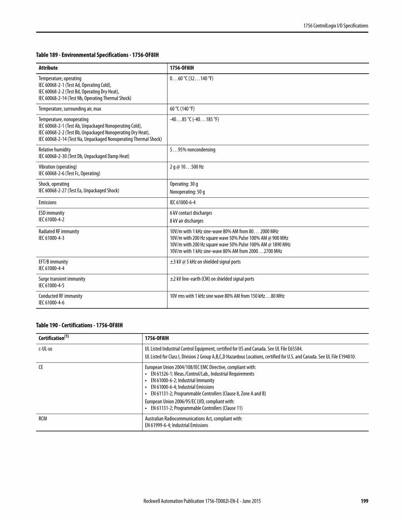
1756 ControlLogix I/O Specifications
Table 189 - Environmental Specifications - 1756-OF8IH
Attribute 1756-OF8IH
Temperature, operatingIEC 60068-2-1 (Test Ad, Operating Cold),IEC 60068-2-2 (Test Bd, Operating Dry Heat),IEC 60068-2-14 (Test Nb, Operating Thermal Shock)
0…60 °C (32…140 °F)
Temperature, surrounding air, max 60 °C (140 °F)
Temperature, nonoperatingIEC 60068-2-1 (Test Ab, Unpackaged Nonoperating Cold),IEC 60068-2-2 (Test Bb, Unpackaged Nonoperating Dry Heat),IEC 60068-2-14 (Test Na, Unpackaged Nonoperating Thermal Shock)
-40…85 °C (-40…185 °F)
Relative humidityIEC 60068-2-30 (Test Db, Unpackaged Damp Heat)
5…95% noncondensing
Vibration (operating)IEC 60068-2-6 (Test Fc, Operating)
2 g @ 10…500 Hz
Shock, operatingIEC 60068-2-27 (Test Ea, Unpackaged Shock)
Operating: 30 gNonoperating: 50 g
Emissions IEC 61000-6-4
ESD immunityIEC 61000-4-2
6 kV contact discharges8 kV air discharges
Radiated RF immunityIEC 61000-4-3
10V/m with 1 kHz sine-wave 80% AM from 80… 2000 MHz10V/m with 200 Hz square wave 50% Pulse 100% AM @ 900 MHz10V/m with 200 Hz square wave 50% Pulse 100% AM @ 1890 MHz10V/m with 1 kHz sine-wave 80% AM from 2000…2700 MHz
EFT/B immunityIEC 61000-4-4
±3 kV @ 5 kHz on shielded signal ports
Surge transient immunityIEC 61000-4-5
±2 kV line-earth (CM) on shielded signal ports
Conducted RF immunityIEC 61000-4-6
10V rms with 1 kHz sine wave 80% AM from 150 kHz…80 MHz
Table 190 - Certifications - 1756-OF8IH
Certification(1) 1756-OF8IH
c-UL-us UL Listed Industrial Control Equipment, certified for US and Canada. See UL File E65584.UL Listed for Class I, Division 2 Group A,B,C,D Hazardous Locations, certified for U.S. and Canada. See UL File E194810.
CE European Union 2004/108/IEC EMC Directive, compliant with:• EN 61326-1; Meas./Control/Lab., Industrial Requirements• EN 61000-6-2; Industrial Immunity• EN 61000-6-4; Industrial Emissions• EN 61131-2; Programmable Controllers (Clause 8, Zone A and B)European Union 2006/95/EC LVD, compliant with:• EN 61131-2; Programmable Controllers (Clause 11)
RCM Australian Radiocommunications Act, compliant with:EN 61999-6-4; Industrial Emissions
Rockwell Automation Publication 1756-TD002I-EN-E - June 2015 199
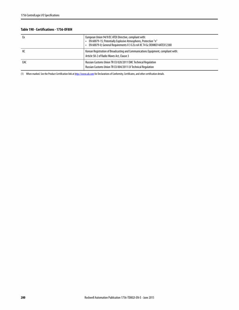
1756 ControlLogix I/O Specifications
Ex European Union 94/9/EC ATEX Directive, compliant with:• EN 60079-15; Potentially Explosive Atmospheres, Protection "n"• EN 60079-0; General Requirements II 3 G Ex nA IIC T4 Gc DEMKO14ATEX1238X
KC Korean Registration of Broadcasting and Communications Equipment, compliant with:Article 58-2 of Radio Waves Act, Clause 3
EAC Russian Customs Union TR CU 020/2011 EMC Technical RegulationRussian Customs Union TR CU 004/2011 LV Technical Regulation
(1) When marked. See the Product Certification link at http://www.ab.com for Declarations of Conformity, Certificates, and other certification details.
Table 190 - Certifications - 1756-OF8IH
200 Rockwell Automation Publication 1756-TD002I-EN-E - June 2015
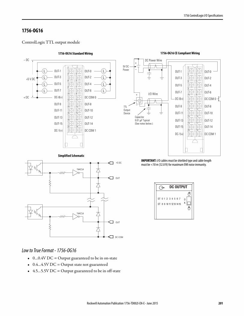
1756 ControlLogix I/O Specifications
1756-OG16
ControlLogix TTL output module
Low to True Format - 1756-OG16• 0…0.4V DC = Output guaranteed to be in on-state• 0.4…4.5V DC = Output state not guaranteed• 4.5…5.5V DC = Output guaranteed to be in off-state
1
3
5
7
9
19
17
15
13
11
2
4
6
8
10
20
18
16
14
12
OUT-1
OUT-3
OUT-5
OUT-7
DC-0(+)
OUT-0
OUT-2
OUT-4
OUT-6
DC COM 0
OUT-9
OUT-11
OUT-13
OUT-15
DC-1(+)
OUT-8
OUT-10
OUT-12
OUT-14
DC COM 1
– DC
+ DC
+5 V DC
1
3
5
7
9
19
17
15
13
11
2
4
6
8
10
20
18
16
14
12
OUT-1
OUT-3
OUT-5
OUT-7
DC-0(+)
OUT-0
OUT-2
OUT-4
OUT-6
DC COM 0
OUT-9
OUT-11
OUT-13
OUT-15
DC-1(+)
OUT-8
OUT-10
OUT-12
OUT-14
DC COM 1
Capacitor0.01 μF Typical (See notes below.)
DC Power Wire
I/O Wire
5V DC Power
+
–
+
–TTL Output Device
DC COM
OUT
74AC14
OUT
+5 DC
74AC14
1756-OG16 Standard Wiring 1756-OG16 CE Compliant Wiring
Simplified SchematicIMPORTANT: I/O cables must be shielded type and cable length must be <10 m (32.8 ft) for maximum EMI noise immunity.
DC OUTPUT
ST 0 1 2 3 4 5 6 7
ST 8 9 10 11 1213 14 15
OK
Rockwell Automation Publication 1756-TD002I-EN-E - June 2015 201
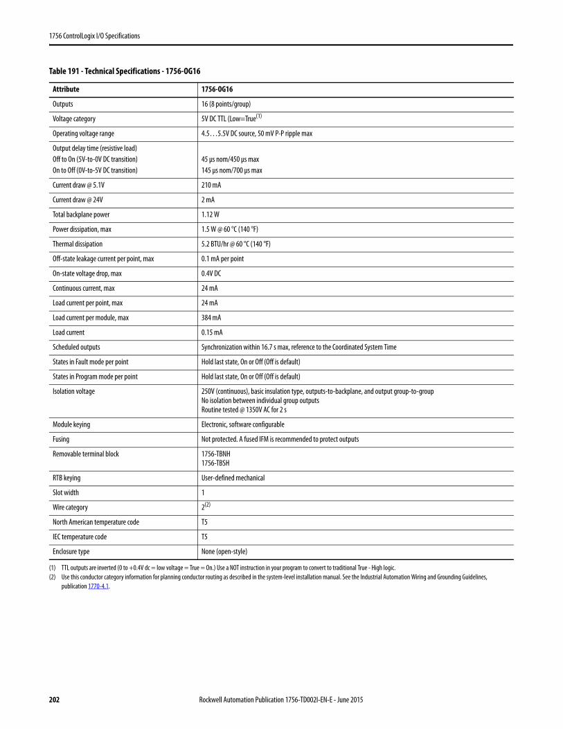
1756 ControlLogix I/O Specifications
Table 191 - Technical Specifications - 1756-OG16
Attribute 1756-OG16
Outputs 16 (8 points/group)
Voltage category 5V DC TTL (Low=True(1)
(1) TTL outputs are inverted (0 to +0.4V dc = low voltage = True = On.) Use a NOT instruction in your program to convert to traditional True - High logic.
Operating voltage range 4.5…5.5V DC source, 50 mV P-P ripple max
Output delay time (resistive load)Off to On (5V-to-0V DC transition)On to Off (0V-to-5V DC transition)
45 μs nom/450 μs max145 μs nom/700 μs max
Current draw @ 5.1V 210 mA
Current draw @ 24V 2 mA
Total backplane power 1.12 W
Power dissipation, max 1.5 W @ 60 °C (140 °F)
Thermal dissipation 5.2 BTU/hr @ 60 °C (140 °F)
Off-state leakage current per point, max 0.1 mA per point
On-state voltage drop, max 0.4V DC
Continuous current, max 24 mA
Load current per point, max 24 mA
Load current per module, max 384 mA
Load current 0.15 mA
Scheduled outputs Synchronization within 16.7 s max, reference to the Coordinated System Time
States in Fault mode per point Hold last state, On or Off (Off is default)
States in Program mode per point Hold last state, On or Off (Off is default)
Isolation voltage 250V (continuous), basic insulation type, outputs-to-backplane, and output group-to-groupNo isolation between individual group outputsRoutine tested @ 1350V AC for 2 s
Module keying Electronic, software configurable
Fusing Not protected. A fused IFM is recommended to protect outputs
Removable terminal block 1756-TBNH1756-TBSH
RTB keying User-defined mechanical
Slot width 1
Wire category 2(2)
(2) Use this conductor category information for planning conductor routing as described in the system-level installation manual. See the Industrial Automation Wiring and Grounding Guidelines, publication 1770-4.1.
North American temperature code T5
IEC temperature code T5
Enclosure type None (open-style)
202 Rockwell Automation Publication 1756-TD002I-EN-E - June 2015

1756 ControlLogix I/O Specifications
Table 192 - Environmental Specifications - 1756-OG16
Attribute 1756-OG16
Temperature, operatingIEC 60068-2-1 (Test Ad, Operating Cold),IEC 60068-2-2 (Test Bd, Operating Dry Heat),IEC 60068-2-14 (Test Nb, Operating Thermal Shock)
0…60 °C (32…140 °F)
Temperature, surrounding air, max 60 °C (140 °F)
Temperature, nonoperatingIEC 60068-2-1 (Test Ab, Unpackaged Nonoperating Cold),IEC 60068-2-2 (Test Bb, Unpackaged Nonoperating Dry Heat),IEC 60068-2-14 (Test Na, Unpackaged Nonoperating Thermal Shock)
-40…85 °C (-40…185 °F)
Relative humidityIEC 60068-2-30 (Test Db, Unpackaged Damp Heat)
5…95% noncondensing
VibrationIEC 60068-2-6 (Test Fc, Operating)
2 g @ 10…500 Hz
Shock, operatingIEC 60068-2-27 (Test Ea, Unpackaged Shock)
30 g
Shock, nonoperatingIEC 60068-2-27 (Test Ea, Unpackaged Shock)
50 g
Emissions CISPR 11, Class A
ESD immunityIEC 61000-4-2
6 kV contact discharges8 kV air discharges
Radiated RF immunityIEC 61000-4-3
10V/m with 1 kHz sine-wave 80% AM from 80… 2000 MHz10V/m with 200 Hz 50% Pulse 100% AM @ 900 MHz10V/m with 200 Hz 50% Pulse 100% AM @ 1890 MHz3V/m with 1 kHz sine-wave 80% AM from 2000…2700 MHz
EFT/B immunityIEC 61000-4-4
±4 kV at 5 kHz on signal ports
Conducted RF immunityIEC 61000-4-6
10V rms with 1 kHz sine-wave 80% AM from 150 kHz…80 MHz
Table 193 - Certifications - 1756-OG16
Certification(1)
(1) When marked. See the Product Certification link at http://www.ab.com for Declarations of Conformity, Certificates, and other certification details.
1756-OG16
UL UL Listed Industrial Control Equipment. See UL File E65584.
CSA CSA Certified Process Control Equipment. See CSA File LR54689C.CSA Certified Process Control Equipment for Class I, Division 2 Group A,B,C,D Hazardous Locations. See CSA File LR69960C.
CE European Union 2004/108/IEC EMC Directive, compliant with:• EN 61326-1; Meas./Control/Lab., Industrial Requirements• EN 61000-6-2; Industrial Immunity• EN 61000-6-4; Industrial Emissions• EN 61131-2; Programmable Controllers (Clause 8, Zone A & B)
C-Tick Australian Radiocommunications Act, compliant with:AS/NZS CISPR 11; Industrial Emissions
Ex European Union 94/9/EC ATEX Directive, compliant with:• EN 60079-15; Potentially Explosive Atmospheres, Protection "n"• EN 60079-0; General Requirements II 3 G Ex nA IIC T5 X Gc
KC Korean Registration of Broadcasting and Communications Equipment, compliant with:Article 58-2 of Radio Waves Act, Clause 3
Rockwell Automation Publication 1756-TD002I-EN-E - June 2015 203
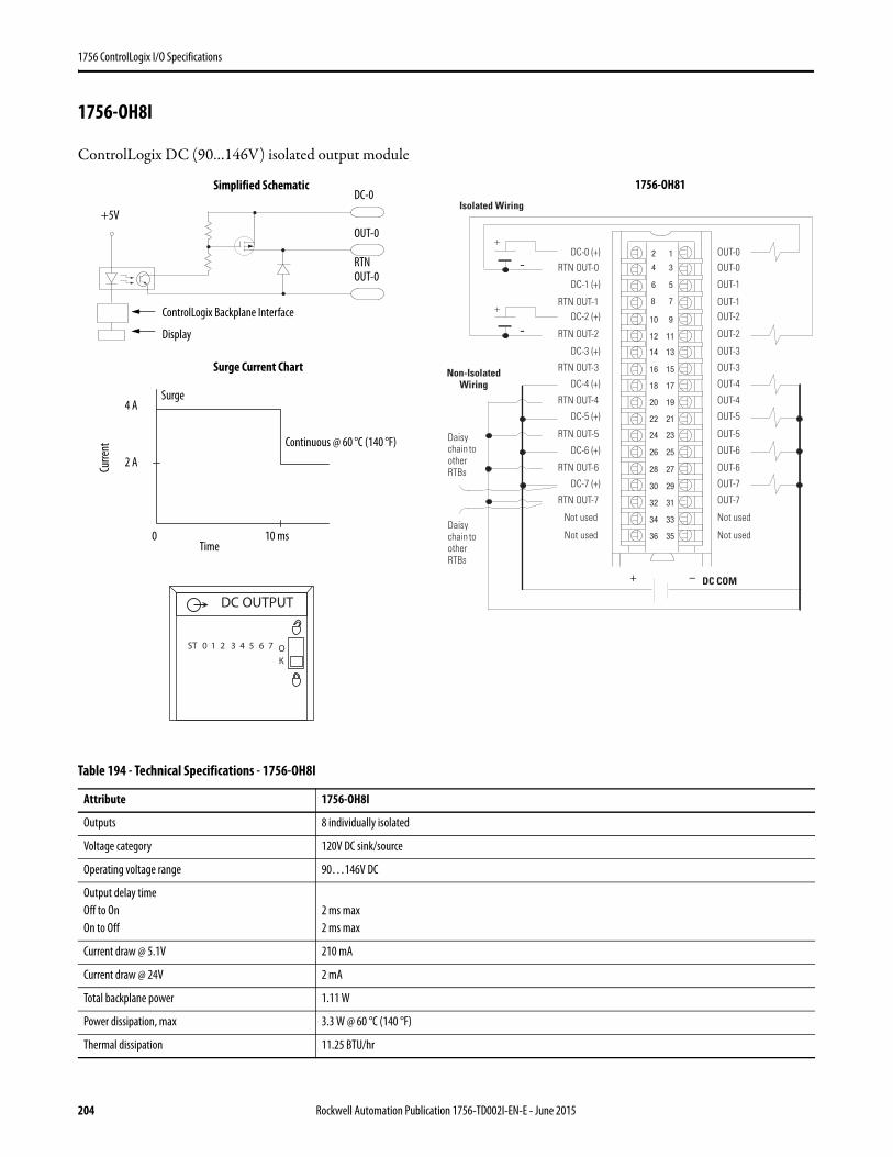
1756 ControlLogix I/O Specifications
1756-OH8I
ControlLogix DC (90…146V) isolated output module
Table 194 - Technical Specifications - 1756-OH8I
Attribute 1756-OH8I
Outputs 8 individually isolated
Voltage category 120V DC sink/source
Operating voltage range 90…146V DC
Output delay timeOff to OnOn to Off
2 ms max 2 ms max
Current draw @ 5.1V 210 mA
Current draw @ 24V 2 mA
Total backplane power 1.11 W
Power dissipation, max 3.3 W @ 60 °C (140 °F)
Thermal dissipation 11.25 BTU/hr
12
34
56
78
910
1112
1314
1516
1718
1920
2122
2324
2526
2728
2930
3132
3334
3536
+
+
-
-
+ –
DC-0 (+)
RTN OUT-0
DC-1 (+)
RTN OUT-1
DC-4 (+)
DC-2 (+)
RTN OUT-2
DC-3 (+)
RTN OUT-3
Not used
RTN OUT-4
DC-5 (+)
RTN OUT-5
DC-6 (+)
RTN OUT-6
DC-7 (+)
RTN OUT-7
Not used
OUT-0
OUT-0
OUT-1
OUT-1
OUT-4
OUT-2
OUT-2
OUT-3
OUT-3
Not used
OUT-4
OUT-5
OUT-5
OUT-6
OUT-6
OUT-7
OUT-7
Not used
DC COM
Isolated Wiring
Daisy chain to other RTBs
Non-Isolated Wiring
Daisy chain to other RTBs
ControlLogix Backplane Interface
RTNOUT-0
DC-0
Display
Surge Current Chart
Simplified Schematic
Surge
+5V
Curre
nt
Time0 10 ms
2 A
4 A
OUT-0
Continuous @ 60 °C (140 °F)
DC OUTPUT
ST 0 1 2 3 4 5 6 7 OK
1756-OH81
204 Rockwell Automation Publication 1756-TD002I-EN-E - June 2015
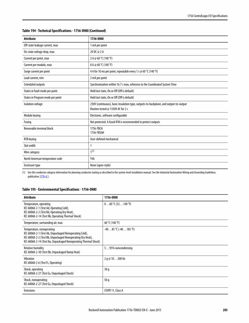
1756 ControlLogix I/O Specifications
Off-state leakage current, max 1 mA per point
On-state voltage drop, max 2V DC @ 2 A
Current per point, max 2 A @ 60 °C (140 °F)
Current per module, max 8 A @ 60 °C (140 °F)
Surge current per point 4 A for 10 ms per point, repeatable every 1 s @ 60 °C (140 °F)
Load current, min 2 mA per point
Scheduled outputs Synchronization within 16.7 s max, reference to the Coordinated System Time
States in Fault mode per point Hold last state, On or Off (Off is default)
States in Program mode per point Hold last state, On or Off (Off is default)
Isolation voltage 250V (continuous), basic insulation type, outputs-to-backplane, and output-to-outputRoutine tested @ 1350V AC for 2 s
Module keying Electronic, software configurable
Fusing Not protected. A fused IFM is recommended to protect outputs
Removable terminal block 1756-TBCH1756-TBS6H
RTB keying User-defined mechanical
Slot width 1
Wire category 1(1)
North American temperature code T4A
Enclosure type None (open-style)
(1) Use this conductor category information for planning conductor routing as described in the system-level installation manual. See the Industrial Automation Wiring and Grounding Guidelines, publication 1770-4.1.
Table 195 - Environmental Specifications - 1756-OH8I
Attribute 1756-OH8I
Temperature, operatingIEC 60068-2-1 (Test Ad, Operating Cold),IEC 60068-2-2 (Test Bd, Operating Dry Heat),IEC 60068-2-14 (Test Nb, Operating Thermal Shock)
0…60 °C (32…140 °F)
Temperature, surrounding air, max 60 °C (140 °F)
Temperature, nonoperatingIEC 60068-2-1 (Test Ab, Unpackaged Nonoperating Cold),IEC 60068-2-2 (Test Bb, Unpackaged Nonoperating Dry Heat),IEC 60068-2-14 (Test Na, Unpackaged Nonoperating Thermal Shock)
-40…85 °C (-40…185 °F)
Relative humidityIEC 60068-2-30 (Test Db, Unpackaged Damp Heat)
5…95% noncondensing
VibrationIEC 60068-2-6 (Test Fc, Operating)
2 g @ 10…500 Hz
Shock, operatingIEC 60068-2-27 (Test Ea, Unpackaged Shock)
30 g
Shock, nonoperatingIEC 60068-2-27 (Test Ea, Unpackaged Shock)
50 g
Emissions CISPR 11, Class A
Table 194 - Technical Specifications - 1756-OH8I (Continued)
Attribute 1756-OH8I
Rockwell Automation Publication 1756-TD002I-EN-E - June 2015 205
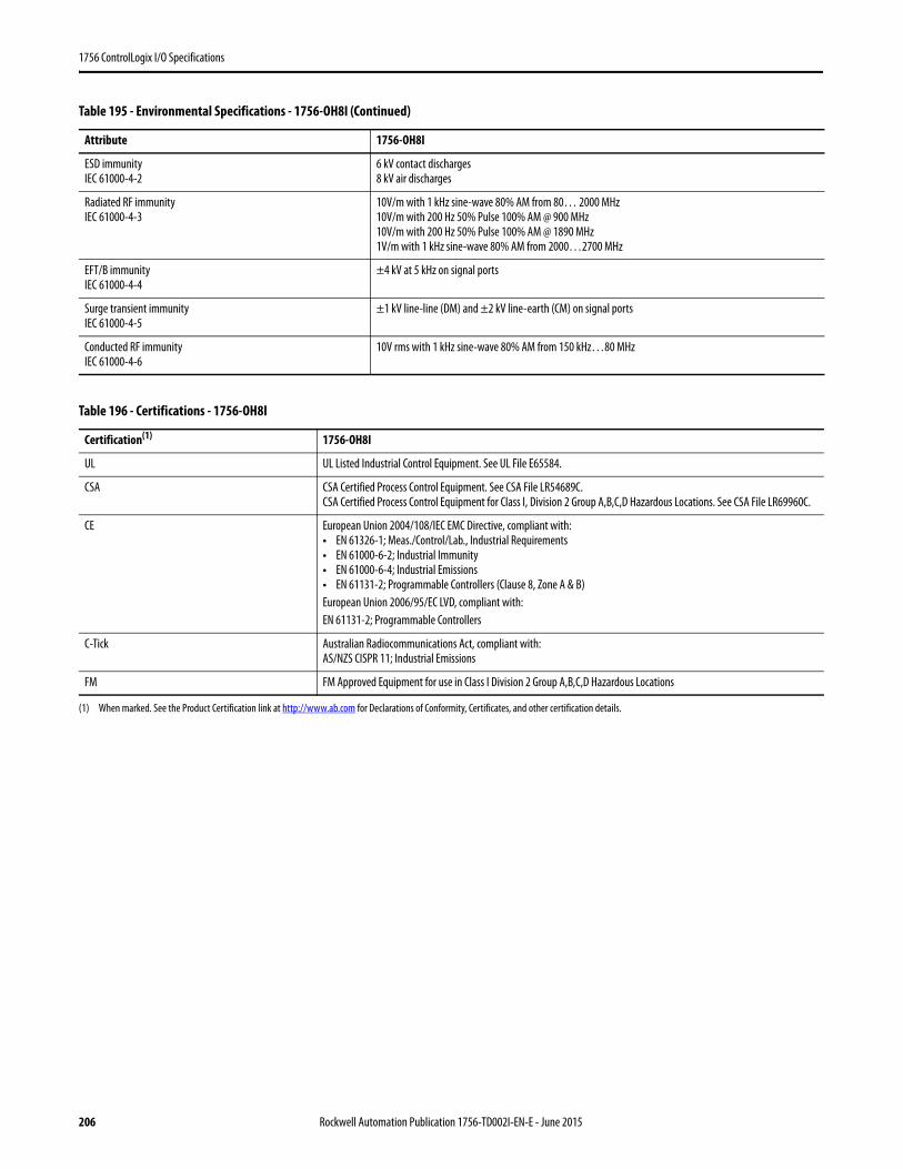
1756 ControlLogix I/O Specifications
ESD immunityIEC 61000-4-2
6 kV contact discharges8 kV air discharges
Radiated RF immunityIEC 61000-4-3
10V/m with 1 kHz sine-wave 80% AM from 80… 2000 MHz10V/m with 200 Hz 50% Pulse 100% AM @ 900 MHz10V/m with 200 Hz 50% Pulse 100% AM @ 1890 MHz1V/m with 1 kHz sine-wave 80% AM from 2000…2700 MHz
EFT/B immunityIEC 61000-4-4
±4 kV at 5 kHz on signal ports
Surge transient immunityIEC 61000-4-5
±1 kV line-line (DM) and ±2 kV line-earth (CM) on signal ports
Conducted RF immunityIEC 61000-4-6
10V rms with 1 kHz sine-wave 80% AM from 150 kHz…80 MHz
Table 196 - Certifications - 1756-OH8I
Certification(1)
(1) When marked. See the Product Certification link at http://www.ab.com for Declarations of Conformity, Certificates, and other certification details.
1756-OH8I
UL UL Listed Industrial Control Equipment. See UL File E65584.
CSA CSA Certified Process Control Equipment. See CSA File LR54689C.CSA Certified Process Control Equipment for Class I, Division 2 Group A,B,C,D Hazardous Locations. See CSA File LR69960C.
CE European Union 2004/108/IEC EMC Directive, compliant with:• EN 61326-1; Meas./Control/Lab., Industrial Requirements• EN 61000-6-2; Industrial Immunity• EN 61000-6-4; Industrial Emissions• EN 61131-2; Programmable Controllers (Clause 8, Zone A & B)European Union 2006/95/EC LVD, compliant with:EN 61131-2; Programmable Controllers
C-Tick Australian Radiocommunications Act, compliant with:AS/NZS CISPR 11; Industrial Emissions
FM FM Approved Equipment for use in Class I Division 2 Group A,B,C,D Hazardous Locations
Table 195 - Environmental Specifications - 1756-OH8I (Continued)
Attribute 1756-OH8I
206 Rockwell Automation Publication 1756-TD002I-EN-E - June 2015
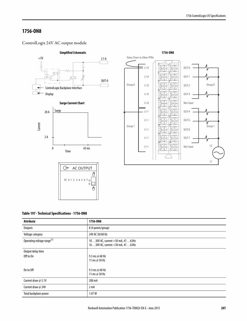
1756 ControlLogix I/O Specifications
1756-ON8
ControlLogix 24V AC output module
Table 197 - Technical Specifications - 1756-ON8
Attribute 1756-ON8
Outputs 8 (4 points/group)
Voltage category 24V AC 50/60 Hz
Operating voltage range(1) 10…30V AC, current >50 mA, 47…63Hz16…30V AC, current <50 mA, 47…63Hz
Output delay timeOff to On
On to Off
9.3 ms @ 60 Hz11 ms @ 50 Hz
9.3 ms @ 60 Hz11 ms @ 50 Hz
Current draw @ 5.1V 200 mA
Current draw @ 24V 2 mA
Total backplane power 1.07 W
12
34
56
78
910
1112
1314
1516
1718
1920
Daisy Chain to Other RTBs
Group 0Group 0
Group 1Group 1
L1-0
L1-0
L1-0
L1-0
L1-1
L1-1
L1-1
L1-1
L1-0
L1-1
OUT-0
OUT-1
OUT-2
OUT-3
OUT-4
OUT-5
OUT-6
OUT-7
Not Used
Not Used
L1
L2
ControlLogix Backplane Interface
OUT-0
L1-0
Display
Surge Current Chart
Simplified Schematic
Surge
+5V
Curre
nt
Time0 43 ms
2 A
20 A
ST 0 1 2 3 4 5 6 7 OK
AC OUTPUT
1756-ON8
Rockwell Automation Publication 1756-TD002I-EN-E - June 2015 207
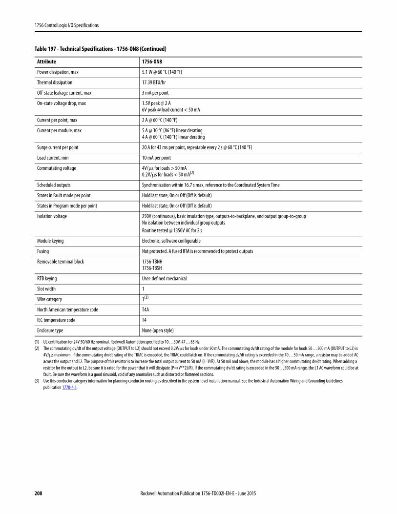
1756 ControlLogix I/O Specifications
Power dissipation, max 5.1 W @ 60 °C (140 °F)
Thermal dissipation 17.39 BTU/hr
Off-state leakage current, max 3 mA per point
On-state voltage drop, max 1.5V peak @ 2 A6V peak @ load current < 50 mA
Current per point, max 2 A @ 60 °C (140 °F)
Current per module, max 5 A @ 30 °C (86 °F) linear derating4 A @ 60 °C (140 °F) linear derating
Surge current per point 20 A for 43 ms per point, repeatable every 2 s @ 60 °C (140 °F)
Load current, min 10 mA per point
Commutating voltage 4V/μs for loads > 50 mA0.2V/μs for loads < 50 mA(2)
Scheduled outputs Synchronization within 16.7 s max, reference to the Coordinated System Time
States in Fault mode per point Hold last state, On or Off (Off is default)
States in Program mode per point Hold last state, On or Off (Off is default)
Isolation voltage 250V (continuous), basic insulation type, outputs-to-backplane, and output group-to-groupNo isolation between individual group outputsRoutine tested @ 1350V AC for 2 s
Module keying Electronic, software configurable
Fusing Not protected. A fused IFM is recommended to protect outputs
Removable terminal block 1756-TBNH1756-TBSH
RTB keying User-defined mechanical
Slot width 1
Wire category 1(3)
North American temperature code T4A
IEC temperature code T4
Enclosure type None (open style)
(1) UL certification for 24V 50/60 Hz nominal. Rockwell Automation specified to 10…30V, 47…63 Hz.(2) The commutating dv/dt of the output voltage (OUTPUT to L2) should not exceed 0.2V/µs for loads under 50 mA. The commutating dv/dt rating of the module for loads 50…500 mA (OUTPUT to L2) is
4V/µs maximum. If the commutating dv/dt rating of the TRIAC is exceeded, the TRIAC could latch on. If the commutating dv/dt rating is exceeded in the 10…50 mA range, a resistor may be added AC across the output and L2. The purpose of this resistor is to increase the total output current to 50 mA (I=V/R). At 50 mA and above, the module has a higher commutating dv/dt rating. When adding a resistor for the output to L2, be sure it is rated for the power that it will dissipate (P=(V**2)/R). If the commutating dv/dt rating is exceeded in the 50…500 mA range, the L1 AC waveform could be at fault. Be sure the waveform is a good sinusoid, void of any anomalies such as distorted or flattened sections.
(3) Use this conductor category information for planning conductor routing as described in the system-level installation manual. See the Industrial Automation Wiring and Grounding Guidelines, publication 1770-4.1.
Table 197 - Technical Specifications - 1756-ON8 (Continued)
Attribute 1756-ON8
208 Rockwell Automation Publication 1756-TD002I-EN-E - June 2015

1756 ControlLogix I/O Specifications
Table 198 - Environmental Specifications - 1756-ON8
Attribute 1756-ON8
Temperature, operatingIEC 60068-2-1 (Test Ad, Operating Cold),IEC 60068-2-2 (Test Bd, Operating Dry Heat),IEC 60068-2-14 (Test Nb, Operating Thermal Shock)
0…60 °C (32…140 °F)
Temperature, surrounding air, max 60 °C (140 °F)
Temperature, nonoperatingIEC 60068-2-1 (Test Ab, Unpackaged Nonoperating Cold),IEC 60068-2-2 (Test Bb, Unpackaged Nonoperating Dry Heat),IEC 60068-2-14 (Test Na, Unpackaged Nonoperating Thermal Shock)
-40…85 °C (-40…185 °F)
Relative humidityIEC 60068-2-30 (Test Db, Unpackaged Damp Heat)
5…95% noncondensing
VibrationIEC 60068-2-6 (Test Fc, Operating)
2 g @ 10…500 Hz
Shock, operatingIEC 60068-2-27 (Test Ea, Unpackaged Shock)
30 g
Shock, nonoperatingIEC 60068-2-27 (Test Ea, Unpackaged Shock)
50 g
Emissions CISPR 11, Class A
ESD immunityIEC 61000-4-2
6 kV contact discharges8 kV air discharges
Radiated RF immunityIEC 61000-4-3
10V/m with 1 kHz sine-wave 80% AM from 80… 2000 MHz10V/m with 200 Hz 50% Pulse 100% AM @ 900 MHz10V/m with 200 Hz 50% Pulse 100% AM @ 1890 MHz3V/m with 1 kHz sine-wave 80% AM from 2000…2700 MHz
EFT/B immunityIEC 61000-4-4
±4 kV at 5 kHz on signal ports
Surge transient immunityIEC 61000-4-5
±1 kV line-line (DM) and ±2 kV line-earth (CM) on signal ports
Conducted RF immunityIEC 61000-4-6
10V rms with 1 kHz sine-wave 80% AM from 150 kHz…80 MHz
Rockwell Automation Publication 1756-TD002I-EN-E - June 2015 209
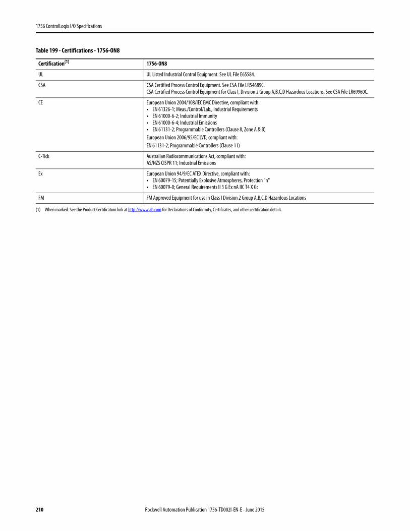
1756 ControlLogix I/O Specifications
Table 199 - Certifications - 1756-ON8
Certification(1) 1756-ON8
UL UL Listed Industrial Control Equipment. See UL File E65584.
CSA CSA Certified Process Control Equipment. See CSA File LR54689C.CSA Certified Process Control Equipment for Class I, Division 2 Group A,B,C,D Hazardous Locations. See CSA File LR69960C.
CE European Union 2004/108/IEC EMC Directive, compliant with:• EN 61326-1; Meas./Control/Lab., Industrial Requirements• EN 61000-6-2; Industrial Immunity• EN 61000-6-4; Industrial Emissions• EN 61131-2; Programmable Controllers (Clause 8, Zone A & B)European Union 2006/95/EC LVD, compliant with:EN 61131-2; Programmable Controllers (Clause 11)
C-Tick Australian Radiocommunications Act, compliant with:AS/NZS CISPR 11; Industrial Emissions
Ex European Union 94/9/EC ATEX Directive, compliant with:• EN 60079-15; Potentially Explosive Atmospheres, Protection "n"• EN 60079-0; General Requirements II 3 G Ex nA IIC T4 X Gc
FM FM Approved Equipment for use in Class I Division 2 Group A,B,C,D Hazardous Locations
(1) When marked. See the Product Certification link at http://www.ab.com for Declarations of Conformity, Certificates, and other certification details.
210 Rockwell Automation Publication 1756-TD002I-EN-E - June 2015
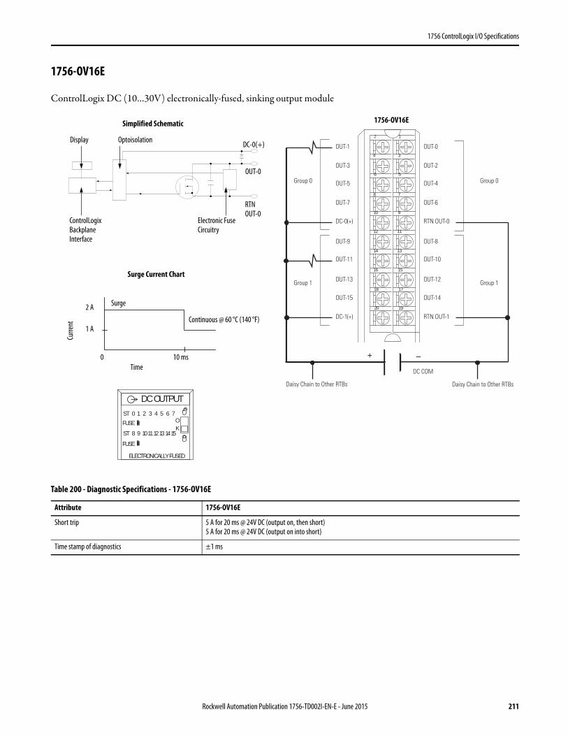
1756 ControlLogix I/O Specifications
1756-OV16E
ControlLogix DC (10…30V) electronically-fused, sinking output module
Table 200 - Diagnostic Specifications - 1756-OV16E
Attribute 1756-OV16E
Short trip 5 A for 20 ms @ 24V DC (output on, then short)5 A for 20 ms @ 24V DC (output on into short)
Time stamp of diagnostics ±1 ms
12
34
56
78
910
1112
1314
1516
1718
1920
+ –
Group 0Group 0
Group 1Group 1
DC COM
OUT-1
OUT-3
OUT-5
OUT-7
OUT-9
OUT-11
OUT-13
OUT-15
DC-0(+)
DC-1(+)
OUT-0
OUT-2
OUT-4
OUT-6
OUT-8
OUT-10
OUT-12
OUT-14
RTN OUT-0
RTN OUT-1
Daisy Chain to Other RTBs Daisy Chain to Other RTBs
ControlLogix Backplane Interface
Electronic Fuse Circuitry
Continuous @ 60 °C (140 °F)
Display Optoisolation
RTNOUT-0
OUT-0
DC-0(+)
Surge Current Chart
Simplified Schematic
Surge
Curre
nt
Time0 10 ms
1 A
2 A
DC OUTPUTST 0 1 2 3 4 5 6 7
ST 8 9 101112131415
OK
FUSE
FUSE
ELECTRONICALLY FUSED
1756-OV16E
Rockwell Automation Publication 1756-TD002I-EN-E - June 2015 211
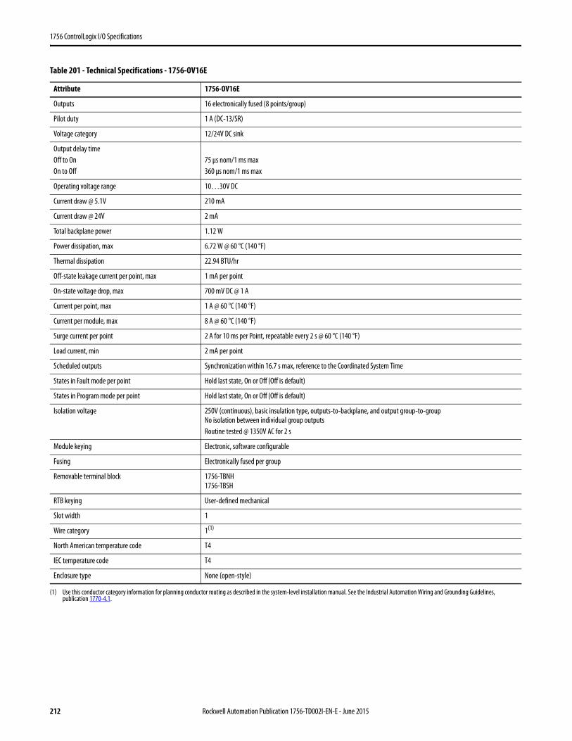
1756 ControlLogix I/O Specifications
Table 201 - Technical Specifications - 1756-OV16E
Attribute 1756-OV16E
Outputs 16 electronically fused (8 points/group)
Pilot duty 1 A (DC-13/SR)
Voltage category 12/24V DC sink
Output delay timeOff to OnOn to Off
75 μs nom/1 ms max360 μs nom/1 ms max
Operating voltage range 10…30V DC
Current draw @ 5.1V 210 mA
Current draw @ 24V 2 mA
Total backplane power 1.12 W
Power dissipation, max 6.72 W @ 60 °C (140 °F)
Thermal dissipation 22.94 BTU/hr
Off-state leakage current per point, max 1 mA per point
On-state voltage drop, max 700 mV DC @ 1 A
Current per point, max 1 A @ 60 °C (140 °F)
Current per module, max 8 A @ 60 °C (140 °F)
Surge current per point 2 A for 10 ms per Point, repeatable every 2 s @ 60 °C (140 °F)
Load current, min 2 mA per point
Scheduled outputs Synchronization within 16.7 s max, reference to the Coordinated System Time
States in Fault mode per point Hold last state, On or Off (Off is default)
States in Program mode per point Hold last state, On or Off (Off is default)
Isolation voltage 250V (continuous), basic insulation type, outputs-to-backplane, and output group-to-groupNo isolation between individual group outputsRoutine tested @ 1350V AC for 2 s
Module keying Electronic, software configurable
Fusing Electronically fused per group
Removable terminal block 1756-TBNH1756-TBSH
RTB keying User-defined mechanical
Slot width 1
Wire category 1(1)
North American temperature code T4
IEC temperature code T4
Enclosure type None (open-style)
(1) Use this conductor category information for planning conductor routing as described in the system-level installation manual. See the Industrial Automation Wiring and Grounding Guidelines, publication 1770-4.1.
212 Rockwell Automation Publication 1756-TD002I-EN-E - June 2015

1756 ControlLogix I/O Specifications
Table 202 - Environmental Specifications - 1756-OV16E
Attribute 1756-OV16E
Temperature, operatingIEC 60068-2-1 (Test Ad, Operating Cold),IEC 60068-2-2 (Test Bd, Operating Dry Heat),IEC 60068-2-14 (Test Nb, Operating Thermal Shock)
0…60 °C (32…140 °F)
Temperature, surrounding air, max 60 °C (140 °F)
Temperature, nonoperatingIEC 60068-2-1 (Test Ab, Unpackaged Nonoperating Cold),IEC 60068-2-2 (Test Bb, Unpackaged Nonoperating Dry Heat),IEC 60068-2-14 (Test Na, Unpackaged Nonoperating Thermal Shock)
-40…85 °C (-40…185 °F)
Relative humidityIEC 60068-2-30 (Test Db, Unpackaged Damp Heat)
5…95% noncondensing
VibrationIEC 60068-2-6 (Test Fc, Operating)
2 g @ 10…500 Hz
Shock, operatingIEC 60068-2-27 (Test Ea, Unpackaged Shock)
30 g
Shock, nonoperatingIEC 60068-2-27 (Test Ea, Unpackaged Shock)
50 g
Emissions CISPR 11, Class A
ESD immunityIEC 61000-4-2
6 kV contact discharges8 kV air discharges
Radiated RF immunityIEC 61000-4-3
10V/m with 1 kHz sine-wave 80% AM from 80… 2000 MHz10V/m with 200 Hz 50% Pulse 100% AM @ 900 MHz10V/m with 200 Hz 50% Pulse 100% AM @ 1890 MHz3V/m with 1 kHz sine-wave 80% AM from 2000…2700 MHz
EFT/B immunityIEC 61000-4-4
±4 kV at 5 kHz on signal ports
Surge transient immunityIEC 61000-4-5
±1 kV line-line (DM) and ±2 kV line-earth (CM) on signal ports
Conducted RF immunityIEC 61000-4-6
10V rms with 1 kHz sine-wave 80% AM from 150 kHz…80 MHz
Rockwell Automation Publication 1756-TD002I-EN-E - June 2015 213

1756 ControlLogix I/O Specifications
Table 203 - Certifications - 1756-OV16E
Certification(1) 1756-OV16E
UL UL Listed Industrial Control Equipment. See UL File E65584.
CSA CSA Certified Process Control Equipment. See CSA File LR54689C.CSA Certified Process Control Equipment for Class I, Division 2 Group A,B,C,D Hazardous Locations. See CSA File LR69960C.
CE European Union 2004/108/IEC EMC Directive, compliant with:• EN 61326-1; Meas./Control/Lab., Industrial Requirements• EN 61000-6-2; Industrial Immunity• EN 61000-6-4; Industrial Emissions• EN 61131-2; Programmable Controllers (Clause 8, Zone A & B)European Union 2006/95/EC LVD, compliant with:EN 61131-2; Programmable Controllers (Clause 11)
C-Tick Australian Radiocommunications Act, compliant with:AS/NZS CISPR 11; Industrial Emissions
Ex European Union 94/9/EC ATEX Directive, compliant with:• EN 60079-15; Potentially Explosive Atmospheres, Protection "n"• EN 60079-0; General Requirements II 3 G Ex nA IIC T4 X Gc
FM FM Approved Equipment for use in Class I Division 2 Group A,B,C,D Hazardous Locations
KC Korean Registration of Broadcasting and Communications Equipment, compliant with:Article 58-2 of Radio Waves Act, Clause 3
(1) When marked. See the Product Certification link at http://www.ab.com for Declarations of Conformity, Certificates, and other certification details.
214 Rockwell Automation Publication 1756-TD002I-EN-E - June 2015
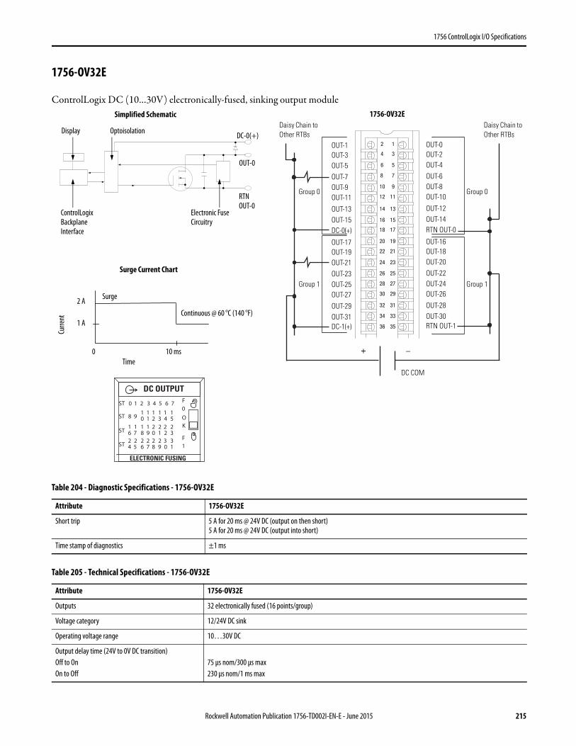
1756 ControlLogix I/O Specifications
1756-OV32E
ControlLogix DC (10…30V) electronically-fused, sinking output module
Table 204 - Diagnostic Specifications - 1756-OV32E
Attribute 1756-OV32E
Short trip 5 A for 20 ms @ 24V DC (output on then short)5 A for 20 ms @ 24V DC (output into short)
Time stamp of diagnostics ±1 ms
Table 205 - Technical Specifications - 1756-OV32E
Attribute 1756-OV32E
Outputs 32 electronically fused (16 points/group)
Voltage category 12/24V DC sink
Operating voltage range 10…30V DC
Output delay time (24V to 0V DC transition)Off to OnOn to Off
75 μs nom/300 μs max230 μs nom/1 ms max
12
34
56
78
910
1112
1314
1516
1718
1920
2122
2324
2526
2728
2930
3132
3334
3536
+ _
Daisy Chain to Other RTBs
Daisy Chain to Other RTBs
Group 0
Group 1
Group 0
Group 1
DC COM
OUT-1OUT-3OUT-5OUT-7OUT-9OUT-11
OUT-13OUT-15DC-0(+)
DC-1(+)
OUT-0OUT-2OUT-4OUT-6OUT-8OUT-10
OUT-12OUT-14RTN OUT-0
RTN OUT-1
OUT-17OUT-19OUT-21OUT-23OUT-25OUT-27
OUT-29OUT-31
OUT-16OUT-18OUT-20OUT-22OUT-24OUT-26
OUT-28OUT-30
ControlLogix Backplane Interface
Electronic Fuse Circuitry
Continuous @ 60 °C (140 °F)
Display Optoisolation
RTNOUT-0
OUT-0
DC-0(+)
Surge Current Chart
Simplified Schematic
Surge
Curre
nt
Time0 10 ms
1 A
2 A
OK
ST 0 1 2 3 4 5 6 7
ST 8 910 21 3 4 5
1 1 1 11
ST 6 718 09 1 2 3
1 2 2 221 1
ST 4 526 87 9 0 1
2 2 2 332 2
DC OUTPUT
ELECTRONIC FUSING
F0
F1
1756-OV32E
Rockwell Automation Publication 1756-TD002I-EN-E - June 2015 215

1756 ControlLogix I/O Specifications
Current draw @ 5.1V 390 mA
Current draw @ 24V 2 mA
Total backplane power 2.04 W
Power dissipation, max 5.88 W @ 60 °C (140 °F)
Thermal dissipation 20.1 BTU/hr
Off-state leakage current per point, max 1 mA per point
On-state voltage drop, max 350 mV DC @ 0.5 A
Current per point, max 0.5 A @ 50 °C (122 °F) linear derating0.35 A @ 60 °C (140 °F)
Current per group, max 8 A @ 50 °C (122 °F) linear derating5 A @ 60 °C (140 °F)
Current per module, max 16 A @ 50 °C (122 °F) linear derating10 A @ 60 °C (140 °F)
Surge current per point 2 A for 10 ms per point, repeatable every 2 s @ 60 °C (140 °F)
Load current, min 2 mA per output
Scheduled outputs Synchronization within 16.7 s max, reference to the Coordinated System Time
States in Fault mode per point Hold last state, On or Off (Off is default)
States in Program mode per point Hold last state, On or Off (Off is default)
Isolation voltage 250V (continuous), basic insulation type, outputs-to-backplane, and output group-to-groupNo isolation between individual group outputsRoutine tested @ 1350V AC for 2 s
Module keying Electronic, software configurable
Fusing Electronically fused per group
Removable terminal block 1756-TBCH1756-TBS6H
RTB keying User-defined mechanical
Slot width 1
Wire category 1(1)
North American temperature code T4
IEC temperature code T4
Enclosure type None (open-style)
(1) Use this conductor category information for planning conductor routing as described in the system-level installation manual. See the Industrial Automation Wiring and Grounding Guidelines, publication 1770-4.1.
Table 205 - Technical Specifications - 1756-OV32E (Continued)
Attribute 1756-OV32E
216 Rockwell Automation Publication 1756-TD002I-EN-E - June 2015

1756 ControlLogix I/O Specifications
Table 206 - Environmental Specifications - 1756-OV32E
Attribute 1756-OV32E
Temperature, operatingIEC 60068-2-1 (Test Ad, Operating Cold),IEC 60068-2-2 (Test Bd, Operating Dry Heat),IEC 60068-2-14 (Test Nb, Operating Thermal Shock)
0…60 °C (32…140 °F)
Temperature, surrounding air, max 60 °C (140 °F)
Temperature, nonoperatingIEC 60068-2-1 (Test Ab, Unpackaged Nonoperating Cold),IEC 60068-2-2 (Test Bb, Unpackaged Nonoperating Dry Heat),IEC 60068-2-14 (Test Na, Unpackaged Nonoperating Thermal Shock)
-40…85 °C (-40…185 °F)
Relative humidityIEC 60068-2-30 (Test Db, Unpackaged Damp Heat)
5…95% noncondensing
VibrationIEC 60068-2-6 (Test Fc, Operating)
2 g @ 10…500 Hz
Shock, operatingIEC 60068-2-27 (Test Ea, Unpackaged Shock)
30 g
Shock, nonoperatingIEC 60068-2-27 (Test Ea, Unpackaged Shock)
50 g
Emissions CISPR 11, Class A
ESD immunityIEC 61000-4-2
6 kV contact discharges8 kV air discharges
Radiated RF immunityIEC 61000-4-3
10V/m with 1 kHz sine-wave 80% AM from 80… 2000 MHz10V/m with 200 Hz 50% Pulse 100% AM @ 900 MHz10V/m with 200 Hz 50% Pulse 100% AM @ 1890 MHz3V/m with 1 kHz sine-wave 80% AM from 2000…2700 MHz
EFT/B immunityIEC 61000-4-4
±4 kV at 5 kHz on signal ports
Surge transient immunityIEC 61000-4-5
±1 kV line-line (DM) and ±2 kV line-earth (CM) on signal ports
Conducted RF immunityIEC 61000-4-6
10V rms with 1 kHz sine-wave 80% AM from 150 kHz…80 MHz
Rockwell Automation Publication 1756-TD002I-EN-E - June 2015 217
1756 ControlLogix I/O Specifications
Table 207 - Certifications - 1756-OV32E
Certification(1) 1756-OV32E
UL UL Listed Industrial Control Equipment. See UL File E65584.
CSA CSA Certified Process Control Equipment. See CSA File LR54689C.CSA Certified Process Control Equipment for Class I, Division 2 Group A,B,C,D Hazardous Locations. See CSA File LR69960C.
CE European Union 2004/108/IEC EMC Directive, compliant with:• EN 61326-1; Meas./Control/Lab., Industrial Requirements• EN 61000-6-2; Industrial Immunity• EN 61000-6-4; Industrial Emissions• EN 61131-2; Programmable Controllers (Clause 8, Zone A & B)European Union 2006/95/EC LVD, compliant with:EN 61131-2; Programmable Controllers (Clause 11)
C-Tick Australian Radiocommunications Act, compliant with:AS/NZS CISPR 11; Industrial Emissions
Ex European Union 94/9/EC ATEX Directive, compliant with:• EN 60079-15; Potentially Explosive Atmospheres, Protection "n"• EN 60079-0; General Requirements II 3 G Ex nA IIC T4 X Gc
KC Korean Registration of Broadcasting and Communications Equipment, compliant with:Article 58-2 of Radio Waves Act, Clause 3
(1) When marked. See the Product Certification link at http://www.ab.com for Declarations of Conformity, Certificates, and other certification details.
218 Rockwell Automation Publication 1756-TD002I-EN-E - June 2015
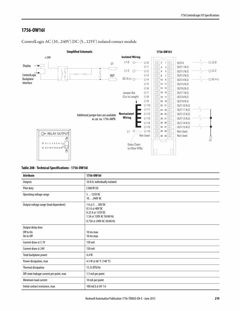
1756 ControlLogix I/O Specifications
1756-OW16I
ControlLogix AC (10…240V) DC (5…125V) isolated contact module
Table 208 - Technical Specifications - 1756-OW16I
Attribute 1756-OW16I
Outputs 16 N.O. individually isolated
Pilot duty C300/R150
Operating voltage range 5…125V DC10…240V AC
Output voltage range (load dependent) 1 A @ 5…30V DC0.5 A @ 48V DC0.22 A @ 125V DC1.5A @ 120V AC 50/60 Hz0.75A @ 240V AC 50/60 Hz
Output delay timeOff to OnOn to Off
10 ms max10 ms max
Current draw @ 5.1V 150 mA
Current draw @ 24V 150 mA
Total backplane power 4.4 W
Power dissipation, max 4.5 W @ 60 °C (140 °F)
Thermal dissipation 15.35 BTU/hr
Off-state leakage current per point, max 1.5 mA per point
Minimum load current 10 mA per point
Initial contact resistance, max 100 mΩ @ 6V 1 A
12
34
56
78
910
1112
1314
1516
1718
1920
2122
2324
2526
2728
2930
3132
3334
3536
Nonisolated Wiring
Isolated Wiring
Daisy Chain to Other RTBs
L1-0L1-1L1-2L1-3
L1-8
L1-4L1-5L1-6L1-7
L1-9L1-10L1-11L1-12L1-13L1-14L1-15
Not Used
OUT-0 OUT-1 N.O.OUT-2 N.O.OUT-3 N.O.
OUT-8 N.O.
OUT-4 N.O.OUT-5 N.O.OUT-6 N.O.OUT-7 N.O.
Not Used
OUT-9 N.O.OUT-10 N.O.OUT-11 N.O.OUT-12 N.O.OUT-13 N.O.OUT-14 N.O.OUT-15 N.ONot UsedL1
Jumper Bar (Cut to Length)
DC-4 (-)
L2
L1-15
L2-0
DC-4 (+)
L1-0
L1-2 L2-2ControlLogix Backplane Interface
Display
OUT
L1
+24V
Simplified Schematic
Additional jumper bars are availableas cat. no. 1756-JMPR.
ST 0 1 2 3 4 5 6 7
ST 8 9 10 11 12 13 14 15
OK
RELAY OUTPUT
1756-OW161
Rockwell Automation Publication 1756-TD002I-EN-E - June 2015 219
1756 ControlLogix I/O Specifications
Switching frequency, max 1 operation/3 s (0.3 Hz at rated load)
Bounce time, mean 1.2 ms
Expected contact life 300 K cycles resistive100 K cycles inductive
Scheduled outputs Synchronization within 16.7 s max, reference to the Coordinated System Time
States in Fault mode per point Hold last state, On or Off (Off is default)
States in Program mode per point Hold last state, On or Off (Off is default)
Isolation voltage 250V (continuous), basic insulation type, outputs-to-backplane, and output-to-outputRoutine tested @ 1350V AC for 2 s
Module keying Electronic, software configurable
Fusing Not protected. A fused IFM can be used to protect outputs. See publication 1492-TD008. However, the ControlLogix system has been agency certified using only the ControlLogix RTBs, that is, 1756-TBCH, 1756-TBNH, 1756-TBSH, and 1756-TBS6H. Any application that requires agency certification of the ControlLogix system using other wiring termination methods may require application-specific approval by the certifying agency.
Removable terminal block 1756-TBCH1756-TBS6H
RTB keying User-defined mechanical
Slot width 1
Wire category 1(1)
North American temperature code T4A
Enclosure type None (open-style)
(1) Use this conductor category information for planning conductor routing as described in the system-level installation manual. See the Industrial Automation Wiring and Grounding Guidelines, publication 1770-4.1.
Table 209 - Environmental Specifications - 1756-OW16I
Attribute 1756-OW16I
Temperature, operatingIEC 60068-2-1 (Test Ad, Operating Cold),IEC 60068-2-2 (Test Bd, Operating Dry Heat),IEC 60068-2-14 (Test Nb, Operating Thermal Shock)
0…60 °C (32…140 °F)
Temperature, surrounding air, max 60 °C (140 °F)
Temperature, nonoperatingIEC 60068-2-1 (Test Ab, Unpackaged Nonoperating Cold),IEC 60068-2-2 (Test Bb, Unpackaged Nonoperating Dry Heat),IEC 60068-2-14 (Test Na, Unpackaged Nonoperating Thermal Shock)
-40…85 °C (-40…185 °F)
Relative humidityIEC 60068-2-30 (Test Db, Unpackaged Damp Heat)
5…95% noncondensing
VibrationIEC 60068-2-6 (Test Fc, Operating)
2 g @ 10…500 Hz
Shock, operatingIEC 60068-2-27 (Test Ea, Unpackaged Shock)
30 g
Shock, nonoperatingIEC 60068-2-27 (Test Ea, Unpackaged Shock)
50 g
Emissions CISPR 11, Class A
ESD immunityIEC 61000-4-2
6 kV contact discharges8 kV air discharges
Table 208 - Technical Specifications - 1756-OW16I (Continued)
Attribute 1756-OW16I
220 Rockwell Automation Publication 1756-TD002I-EN-E - June 2015

1756 ControlLogix I/O Specifications
Radiated RF immunityIEC 61000-4-3
10V/m with 1 kHz sine-wave 80% AM from 80… 2000 MHz10V/m with 200 Hz 50% Pulse 100% AM @ 900 MHz10V/m with 200 Hz 50% Pulse 100% AM @ 1890 MHz3V/m with 1 kHz sine-wave 80% AM from 2000…2700 MHz
EFT/B immunityIEC 61000-4-4
±4 kV at 5 kHz on signal ports
Surge transient immunityIEC 61000-4-5
±1 kV line-line (DM) and ±2 kV line-earth (CM) on signal ports
Conducted RF immunityIEC 61000-4-6
10V rms with 1 kHz sine-wave 80% AM from 150 kHz…80 MHz
Oscillatory surge withstandIEEE C37.90.1
3 kV
Table 210 - Certifications - 1756-OW16I
Certification(1) 1756-OW16I
UL UL Listed Industrial Control Equipment. See UL File E65584.
CSA CSA Certified Process Control Equipment. See CSA File LR54689C.CSA Certified Process Control Equipment for Class I, Division 2 Group A,B,C,D Hazardous Locations. See CSA File LR69960C.
CE European Union 2004/108/IEC EMC Directive, compliant with:• EN 61326-1; Meas./Control/Lab., Industrial Requirements• EN 61000-6-2; Industrial Immunity• EN 61000-6-4; Industrial Emissions• EN 61131-2; Programmable Controllers (Clause 8, Zone A & B)European Union 2006/95/EC LVD, compliant with:EN 61131-2; Programmable Controllers
C-Tick Australian Radiocommunications Act, compliant with:AS/NZS CISPR 11; Industrial Emissions
FM FM Approved Equipment for use in Class I Division 2 Group A,B,C,D Hazardous Locations
KC Korean Registration of Broadcasting and Communications Equipment, compliant with:Article 58-2 of Radio Waves Act, Clause 3
(1) When marked. See the Product Certification link at http://www.ab.com for Declarations of Conformity, Certificates, and other certification details.
Table 209 - Environmental Specifications - 1756-OW16I (Continued)
Attribute 1756-OW16I
Rockwell Automation Publication 1756-TD002I-EN-E - June 2015 221
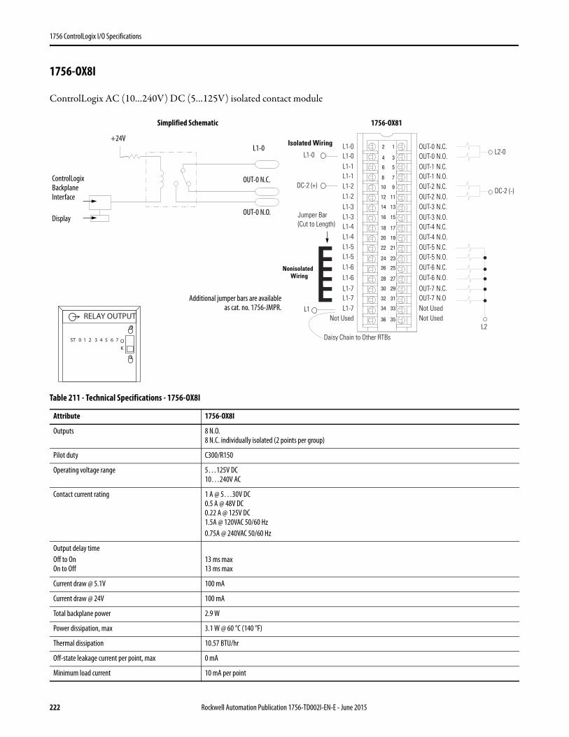
1756 ControlLogix I/O Specifications
1756-OX8I
ControlLogix AC (10…240V) DC (5…125V) isolated contact module
Table 211 - Technical Specifications - 1756-OX8I
Attribute 1756-OX8I
Outputs 8 N.O.8 N.C. individually isolated (2 points per group)
Pilot duty C300/R150
Operating voltage range 5…125V DC10…240V AC
Contact current rating 1 A @ 5…30V DC0.5 A @ 48V DC0.22 A @ 125V DC1.5A @ 120VAC 50/60 Hz0.75A @ 240VAC 50/60 Hz
Output delay timeOff to OnOn to Off
13 ms max13 ms max
Current draw @ 5.1V 100 mA
Current draw @ 24V 100 mA
Total backplane power 2.9 W
Power dissipation, max 3.1 W @ 60 °C (140 °F)
Thermal dissipation 10.57 BTU/hr
Off-state leakage current per point, max 0 mA
Minimum load current 10 mA per point
12
34
56
78
910
1112
1314
1516
1718
1920
2122
2324
2526
2728
2930
3132
3334
3536
Nonisolated Wiring
Isolated Wiring
Daisy Chain to Other RTBs
L1-0L1-0L1-1L1-1
L1-4
L1-2L1-2L1-3L1-3
L1-4L1-5L1-5L1-6L1-6L1-7L1-7
Not Used
OUT-0 N.C.OUT-0 N.O.OUT-1 N.C.OUT-1 N.O.
OUT-4 N.C.
OUT-2 N.C.OUT-2 N.O.OUT-3 N.C.OUT-3 N.O.
Not Used
OUT-4 N.O.OUT-5 N.C.OUT-5 N.O.OUT-6 N.C.OUT-6 N.O.OUT-7 N.C.OUT-7 N.ONot UsedL1
DC-2 (-)
L2
L1-7
L2-0
DC-2 (+)
L1-0
Jumper Bar (Cut to Length)
ControlLogix Backplane Interface
+24V
Display
L1-0
OUT-0 N.C.
OUT-0 N.O.
Simplified Schematic
Additional jumper bars are availableas cat. no. 1756-JMPR.
ST 0 1 2 3 4 5 6 7 OK
RELAY OUTPUT
1756-OX81
222 Rockwell Automation Publication 1756-TD002I-EN-E - June 2015
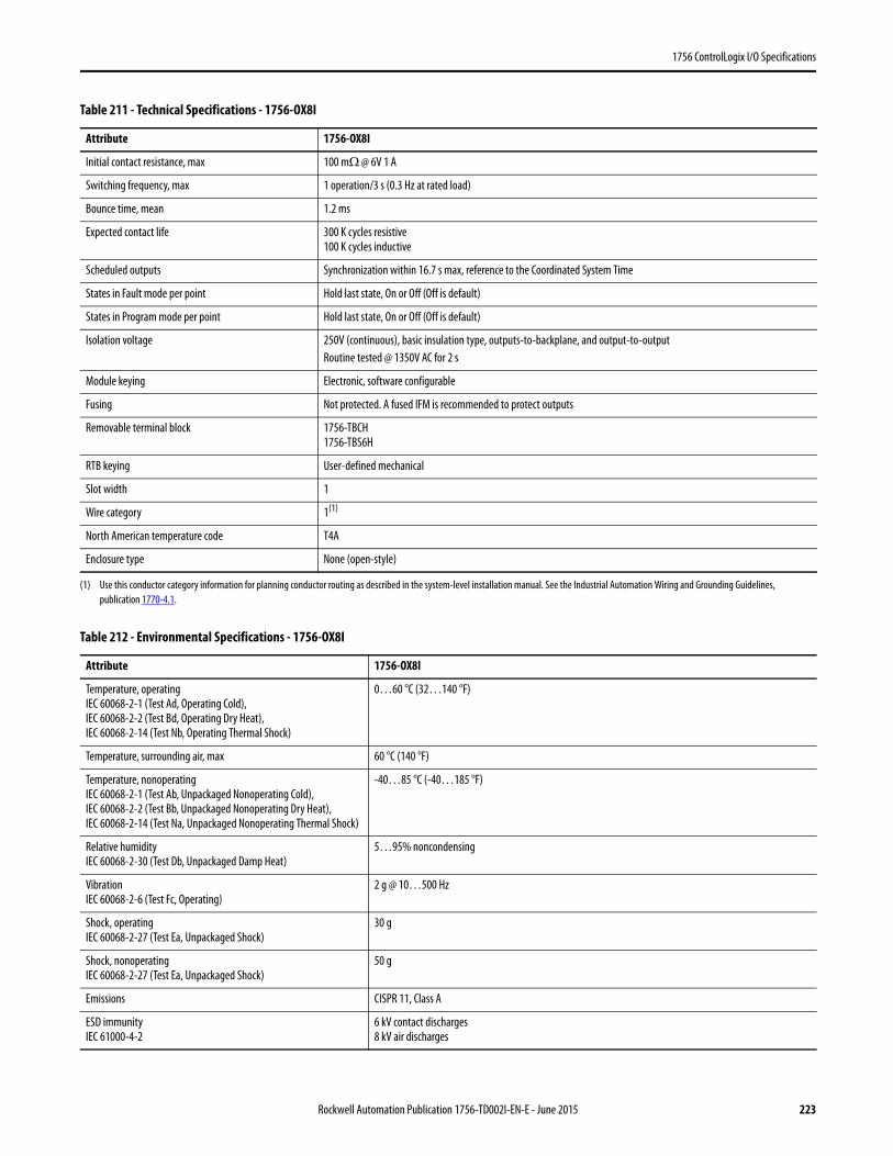
1756 ControlLogix I/O Specifications
Initial contact resistance, max 100 mΩ @ 6V 1 A
Switching frequency, max 1 operation/3 s (0.3 Hz at rated load)
Bounce time, mean 1.2 ms
Expected contact life 300 K cycles resistive100 K cycles inductive
Scheduled outputs Synchronization within 16.7 s max, reference to the Coordinated System Time
States in Fault mode per point Hold last state, On or Off (Off is default)
States in Program mode per point Hold last state, On or Off (Off is default)
Isolation voltage 250V (continuous), basic insulation type, outputs-to-backplane, and output-to-outputRoutine tested @ 1350V AC for 2 s
Module keying Electronic, software configurable
Fusing Not protected. A fused IFM is recommended to protect outputs
Removable terminal block 1756-TBCH1756-TBS6H
RTB keying User-defined mechanical
Slot width 1
Wire category 1(1)
North American temperature code T4A
Enclosure type None (open-style)
(1) Use this conductor category information for planning conductor routing as described in the system-level installation manual. See the Industrial Automation Wiring and Grounding Guidelines, publication 1770-4.1.
Table 212 - Environmental Specifications - 1756-OX8I
Attribute 1756-OX8I
Temperature, operatingIEC 60068-2-1 (Test Ad, Operating Cold),IEC 60068-2-2 (Test Bd, Operating Dry Heat),IEC 60068-2-14 (Test Nb, Operating Thermal Shock)
0…60 °C (32…140 °F)
Temperature, surrounding air, max 60 °C (140 °F)
Temperature, nonoperatingIEC 60068-2-1 (Test Ab, Unpackaged Nonoperating Cold),IEC 60068-2-2 (Test Bb, Unpackaged Nonoperating Dry Heat),IEC 60068-2-14 (Test Na, Unpackaged Nonoperating Thermal Shock)
-40…85 °C (-40…185 °F)
Relative humidityIEC 60068-2-30 (Test Db, Unpackaged Damp Heat)
5…95% noncondensing
VibrationIEC 60068-2-6 (Test Fc, Operating)
2 g @ 10…500 Hz
Shock, operatingIEC 60068-2-27 (Test Ea, Unpackaged Shock)
30 g
Shock, nonoperatingIEC 60068-2-27 (Test Ea, Unpackaged Shock)
50 g
Emissions CISPR 11, Class A
ESD immunityIEC 61000-4-2
6 kV contact discharges8 kV air discharges
Table 211 - Technical Specifications - 1756-OX8I
Attribute 1756-OX8I
Rockwell Automation Publication 1756-TD002I-EN-E - June 2015 223
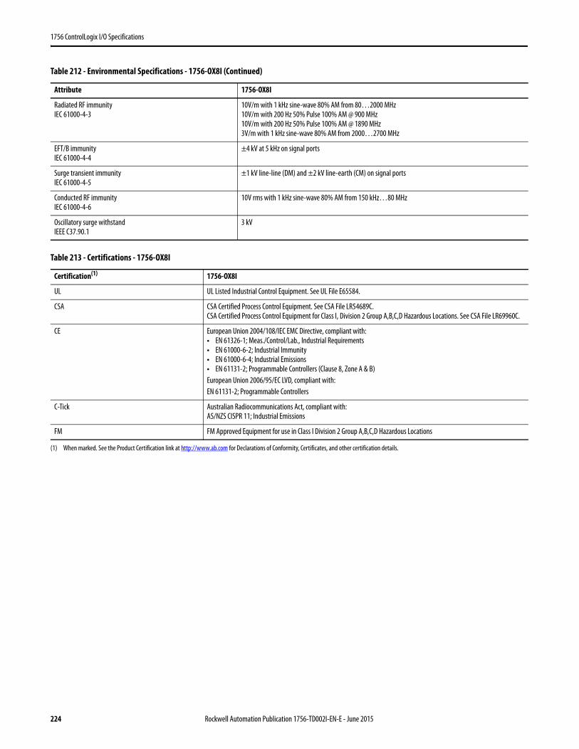
1756 ControlLogix I/O Specifications
Radiated RF immunityIEC 61000-4-3
10V/m with 1 kHz sine-wave 80% AM from 80…2000 MHz10V/m with 200 Hz 50% Pulse 100% AM @ 900 MHz10V/m with 200 Hz 50% Pulse 100% AM @ 1890 MHz3V/m with 1 kHz sine-wave 80% AM from 2000…2700 MHz
EFT/B immunityIEC 61000-4-4
±4 kV at 5 kHz on signal ports
Surge transient immunityIEC 61000-4-5
±1 kV line-line (DM) and ±2 kV line-earth (CM) on signal ports
Conducted RF immunityIEC 61000-4-6
10V rms with 1 kHz sine-wave 80% AM from 150 kHz…80 MHz
Oscillatory surge withstandIEEE C37.90.1
3 kV
Table 213 - Certifications - 1756-OX8I
Certification(1)
(1) When marked. See the Product Certification link at http://www.ab.com for Declarations of Conformity, Certificates, and other certification details.
1756-OX8I
UL UL Listed Industrial Control Equipment. See UL File E65584.
CSA CSA Certified Process Control Equipment. See CSA File LR54689C.CSA Certified Process Control Equipment for Class I, Division 2 Group A,B,C,D Hazardous Locations. See CSA File LR69960C.
CE European Union 2004/108/IEC EMC Directive, compliant with:• EN 61326-1; Meas./Control/Lab., Industrial Requirements• EN 61000-6-2; Industrial Immunity• EN 61000-6-4; Industrial Emissions• EN 61131-2; Programmable Controllers (Clause 8, Zone A & B)European Union 2006/95/EC LVD, compliant with:EN 61131-2; Programmable Controllers
C-Tick Australian Radiocommunications Act, compliant with:AS/NZS CISPR 11; Industrial Emissions
FM FM Approved Equipment for use in Class I Division 2 Group A,B,C,D Hazardous Locations
Table 212 - Environmental Specifications - 1756-OX8I (Continued)
Attribute 1756-OX8I
224 Rockwell Automation Publication 1756-TD002I-EN-E - June 2015

1756 ControlLogix I/O Specifications
1756-CFM
ControlLogix configurable flow meter module
Shield Ground
Input Device
Z0 12-24V DC
Z0 5V DC
Z0 Return
Customer VCC
F0
F0 Return
Not Used
Not Used
Output 0
Customer VCC
Z1 12-24V DC
Z1 5V DC
Z1 RET
Not Used
Customer Common
Not Used
Output 1
F1
F1 Return
12
34
56
78
910
1112
1314
1516
1718
1920Customer Common
+
–
12
34
56
78
910
1112
1314
1516
1718
1920
Load
+
–
Z0 12-24V DC
Z0 5V DC
Z0 Return
Customer VCC
F0
F0 Return
Not Used
Not Used
Output 0
Customer VCC
Z1 12-24V DC
Z1 5V DC
Z1 RET
Not Used
Customer Common
Not Used
Output 1
F1
F1 Return
Customer Common Load
+
–+
–
This wiring diagram can be used in applications with 50 mV (magnetic pickup), 1.3V (TTL), or 4V (preamp level) thresholds. You must use RSLogix™ 5000 software to choose the appropriate threshold level for your specific application.
1756-CFM Standard Magnetic Pickup 1756-CFM Standard Output
Rockwell Automation Publication 1756-TD002I-EN-E - June 2015 225
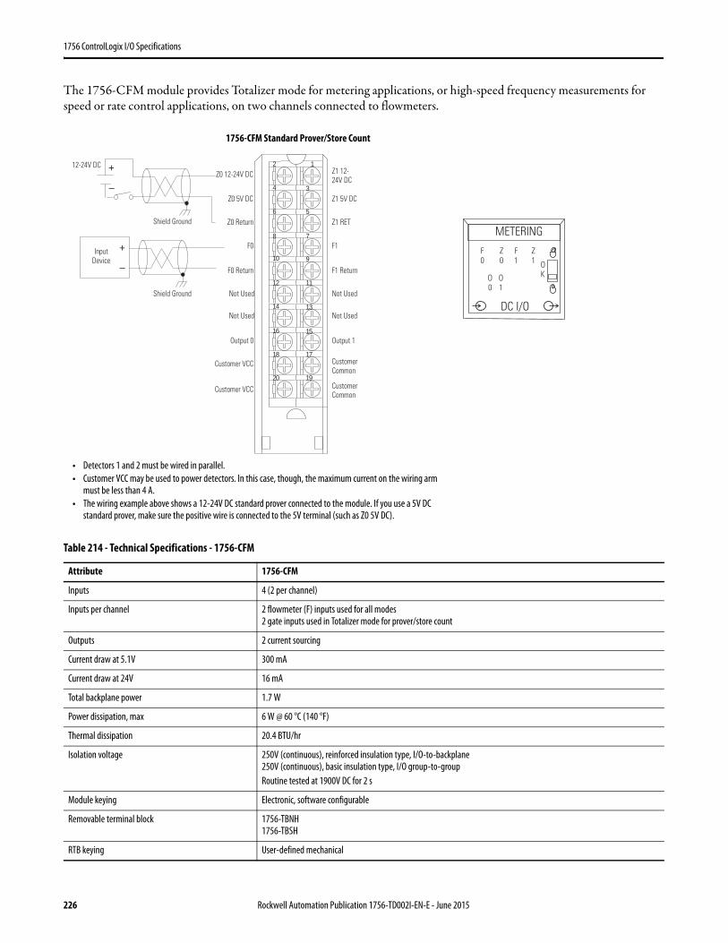
1756 ControlLogix I/O Specifications
The 1756-CFM module provides Totalizer mode for metering applications, or high-speed frequency measurements for speed or rate control applications, on two channels connected to flowmeters.
Table 214 - Technical Specifications - 1756-CFM
Attribute 1756-CFM
Inputs 4 (2 per channel)
Inputs per channel 2 flowmeter (F) inputs used for all modes2 gate inputs used in Totalizer mode for prover/store count
Outputs 2 current sourcing
Current draw at 5.1V 300 mA
Current draw at 24V 16 mA
Total backplane power 1.7 W
Power dissipation, max 6 W @ 60 °C (140 °F)
Thermal dissipation 20.4 BTU/hr
Isolation voltage 250V (continuous), reinforced insulation type, I/O-to-backplane250V (continuous), basic insulation type, I/O group-to-groupRoutine tested at 1900V DC for 2 s
Module keying Electronic, software configurable
Removable terminal block 1756-TBNH1756-TBSH
RTB keying User-defined mechanical
Shield Ground
Input Device
12
34
56
78
910
1112
1314
1516
1718
1920
+
–
Z0 12-24V DC
Z0 5V DC
Z0 Return
Customer VCC
F0
F0 Return
Not Used
Not Used
Output 0
Customer VCC
Z1 12- 24V DC
Z1 5V DC
Z1 RET
Not Used
Customer Common
Not Used
Output 1
F1
F1 Return
Customer Common
12-24V DC +
–
Shield Ground
• Detectors 1 and 2 must be wired in parallel.• Customer VCC may be used to power detectors. In this case, though, the maximum current on the wiring arm
must be less than 4 A.• The wiring example above shows a 12-24V DC standard prover connected to the module. If you use a 5V DC
standard prover, make sure the positive wire is connected to the 5V terminal (such as Z0 5V DC).
METERING
DC I/O
OK
F0
Z0
F1
Z1
O0
O1
1756-CFM Standard Prover/Store Count
226 Rockwell Automation Publication 1756-TD002I-EN-E - June 2015
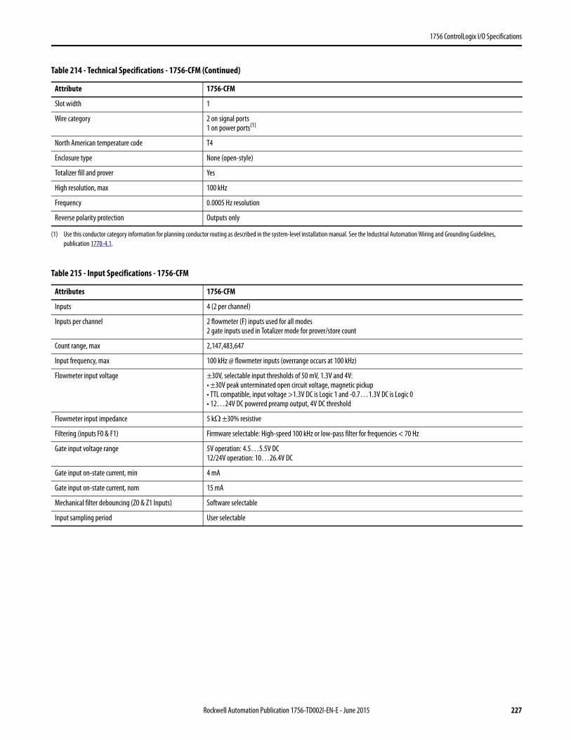
1756 ControlLogix I/O Specifications
Slot width 1
Wire category 2 on signal ports1 on power ports(1)
North American temperature code T4
Enclosure type None (open-style)
Totalizer fill and prover Yes
High resolution, max 100 kHz
Frequency 0.0005 Hz resolution
Reverse polarity protection Outputs only
(1) Use this conductor category information for planning conductor routing as described in the system-level installation manual. See the Industrial Automation Wiring and Grounding Guidelines, publication 1770-4.1.
Table 215 - Input Specifications - 1756-CFM
Attributes 1756-CFM
Inputs 4 (2 per channel)
Inputs per channel 2 flowmeter (F) inputs used for all modes2 gate inputs used in Totalizer mode for prover/store count
Count range, max 2,147,483,647
Input frequency, max 100 kHz @ flowmeter inputs (overrange occurs at 100 kHz)
Flowmeter input voltage ±30V, selectable input thresholds of 50 mV, 1.3V and 4V:• ±30V peak unterminated open circuit voltage, magnetic pickup• TTL compatible, input voltage >1.3V DC is Logic 1 and -0.7…1.3V DC is Logic 0• 12…24V DC powered preamp output, 4V DC threshold
Flowmeter input impedance 5 kΩ ±30% resistive
Filtering (inputs F0 & F1) Firmware selectable: High-speed 100 kHz or low-pass filter for frequencies < 70 Hz
Gate input voltage range 5V operation: 4.5…5.5V DC12/24V operation: 10…26.4V DC
Gate input on-state current, min 4 mA
Gate input on-state current, nom 15 mA
Mechanical filter debouncing (Z0 & Z1 Inputs) Software selectable
Input sampling period User selectable
Table 214 - Technical Specifications - 1756-CFM (Continued)
Attribute 1756-CFM
Rockwell Automation Publication 1756-TD002I-EN-E - June 2015 227

1756 ControlLogix I/O Specifications
Table 216 - Output Specifications - 1756-CFM
Attribute 1756-CFM
Outputs 2 current sourcing
Output voltage source Customer supplied
Output voltage range, nom(1) 5V operation: 4.5…5.5V DC for 3…20 mA load per point12/24V operation: 10…31.2V DC for 40 mA…1 A load per point
Output type IEC 1A 24V DC
Output Current per point(1) 1 A @ 10…31.2V DC20 mA @ 4.5…5.5V DC(2)
Surge current 2 A for 50 ms, repeatable every 2 s
Off-state leakage current, max < 300 μA @ 31.2V DC
On-state voltage drop, max 0.6 Ω x current
Output control Any number of outputs is assignable to any of 2 flowmeter channelsEach output can have 2 “turn-on” and “turn-off” preset values
Output switching time < 50 μs turn on, <300 μs turn offOutputs triggered by Total; all other “turn-on” and “turn-off” times <1ms
Overload current Electronic (< 4A)
Output short circuit protection Electronic (No indication of fault. Remove overload and toggle output on/off to restore.)
Output reverse polarity protection Yes (If wired incorrectly, module outputs may be permanently disabled.)
(1) UL rating for 24V DC, 24VA.(2) All outputs can be on simultaneously without derating.
Table 217 - Environmental Specifications - 1756-CFM
Attribute 1756-CFM
Temperature, operatingIEC 60068-2-1 (Test Ad, Operating Cold),IEC 60068-2-2 (Test Bd, Operating Dry Heat),IEC 60068-2-14 (Test Nb, Operating Thermal Shock)
0…60 °C (32…140 °F)
Temperature, surrounding air, max 60 °C (140 °F)
Temperature, nonoperatingIEC 60068-2-1 (Test Ab, Unpackaged Nonoperating Cold),IEC 60068-2-2 (Test Bb, Unpackaged Nonoperating Dry Heat),IEC 60068-2-14 (Test Na, Unpackaged Nonoperating Thermal Shock)
-40…85 °C (-40…185 °F)
Relative humidityIEC 60068-2-30 (Test Db, Unpackaged Damp Heat)
5…95% noncondensing
VibrationIEC 60068-2-6 (Test Fc, Operating)
2 g @ 10…500 Hz
Shock, operatingIEC 60068-2-27 (Test Ea, Unpackaged Shock)
30 g
Shock, nonoperatingIEC 60068-2-27 (Test Ea, Unpackaged Shock)
50 g
Emissions CISPR 11, Class A
ESD immunityIEC 61000-4-2
6 kV contact discharges8 kV air discharges
Radiated RF immunityIEC 61000-4-3
10V/m with 1k Hz sine-wave 80% AM from 80… 2000 MHz10V/m with 200 Hz 50% Pulse 100% AM @ 900 MHz10V/m with 200 Hz 50% Pulse 100% AM @ 1890 MHz3V/m with 1 kHz sine-wave 80% AM from 2000…2700 MHz
228 Rockwell Automation Publication 1756-TD002I-EN-E - June 2015
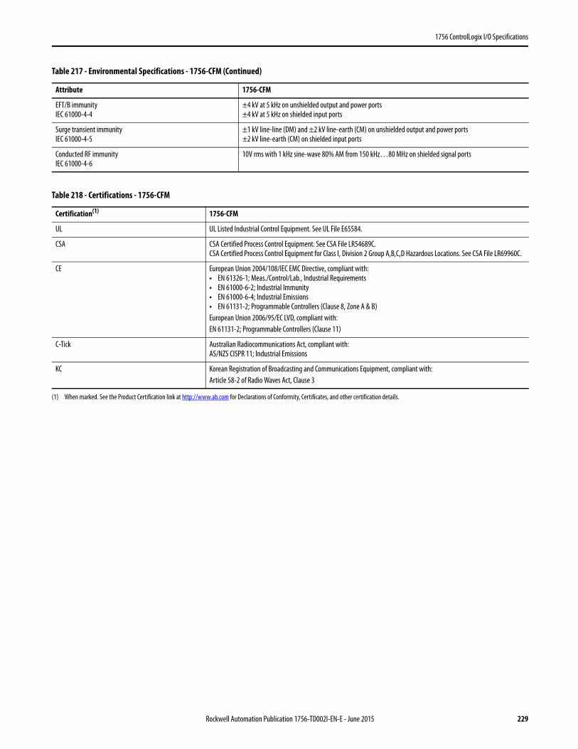
1756 ControlLogix I/O Specifications
EFT/B immunityIEC 61000-4-4
±4 kV at 5 kHz on unshielded output and power ports±4 kV at 5 kHz on shielded input ports
Surge transient immunityIEC 61000-4-5
±1 kV line-line (DM) and ±2 kV line-earth (CM) on unshielded output and power ports±2 kV line-earth (CM) on shielded input ports
Conducted RF immunityIEC 61000-4-6
10V rms with 1 kHz sine-wave 80% AM from 150 kHz…80 MHz on shielded signal ports
Table 218 - Certifications - 1756-CFM
Certification(1)
(1) When marked. See the Product Certification link at http://www.ab.com for Declarations of Conformity, Certificates, and other certification details.
1756-CFM
UL UL Listed Industrial Control Equipment. See UL File E65584.
CSA CSA Certified Process Control Equipment. See CSA File LR54689C.CSA Certified Process Control Equipment for Class I, Division 2 Group A,B,C,D Hazardous Locations. See CSA File LR69960C.
CE European Union 2004/108/IEC EMC Directive, compliant with:• EN 61326-1; Meas./Control/Lab., Industrial Requirements• EN 61000-6-2; Industrial Immunity• EN 61000-6-4; Industrial Emissions• EN 61131-2; Programmable Controllers (Clause 8, Zone A & B)European Union 2006/95/EC LVD, compliant with:EN 61131-2; Programmable Controllers (Clause 11)
C-Tick Australian Radiocommunications Act, compliant with:AS/NZS CISPR 11; Industrial Emissions
KC Korean Registration of Broadcasting and Communications Equipment, compliant with:Article 58-2 of Radio Waves Act, Clause 3
Table 217 - Environmental Specifications - 1756-CFM (Continued)
Attribute 1756-CFM
Rockwell Automation Publication 1756-TD002I-EN-E - June 2015 229
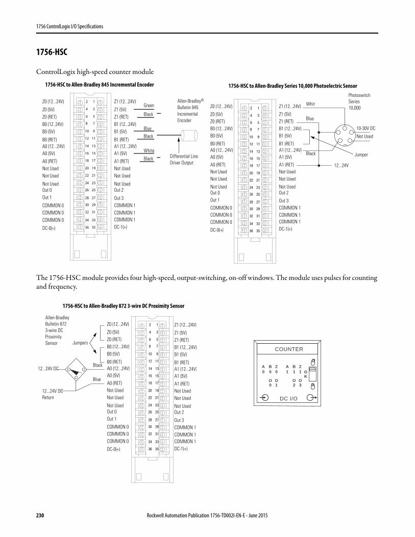
1756 ControlLogix I/O Specifications
1756-HSC
ControlLogix high-speed counter module
The 1756-HSC module provides four high-speed, output-switching, on-off windows. The module uses pulses for counting and frequency.
12
34
56
78
910
1112
1314
1516
1718
1920
2122
2324
2526
2728
2930
3132
3334
3536
Z1 (12...24V)
Z1 (5V)Z1 (RET)B1 (12...24V)B1 (5V)
B1 (RET)A1 (12...24V)A1 (5V)
A1 (RET)Not UsedNot Used
Not Used
Z0 (12...24V)
Z0 (5V)Z0 (RET)B0 (12..24V)B0 (5V)
B0 (RET)A0 (12...24V)A0 (5V)
A0 (RET)Not UsedNot Used
Not Used
COMMON 0COMMON 0COMMON 0
DC-0(+)
Out 2
Out 3COMMON 1COMMON 1COMMON 1DC-1(+)
Out 0Out 1
Black
Black
White
Black
Blue
GreenAllen-Bradley® Bulletin 845 IncrementalEncoder
Differential Line Driver Output
12
34
56
78
910
1112
1314
1516
1718
1920
2122
2324
2526
2728
2930
3132
3334
3536
JumperBlack
Blue
Whit
Not Used
10-30V DC
Photoswitch Series 10,000 Z1 (12...24V)
Z1 (5V)Z1 (RET)B1 (12...24V)B1 (5V)
B1 (RET)A1 (12...24V)A1 (5V)
A1 (RET)Not UsedNot Used
Not Used
Z0 (12...24V)
Z0 (5V)Z0 (RET)B0 (12...24V)B0 (5V)
B0 (RET)A0 (12...24V)A0 (5V)
A0 (RET)Not UsedNot Used
Not Used
COMMON 0COMMON 0COMMON 0
DC-0(+)
Out 2
Out 3COMMON 1COMMON 1COMMON 1DC-1(+)
Out 0Out 1
12...24V
1756-HSC to Allen-Bradley 845 Incremental Encoder 1756-HSC to Allen-Bradley Series 10,000 Photoelectric Sensor
12
34
56
78
910
1112
1314
1516
1718
1920
2122
2324
2526
2728
2930
3132
3334
3536
Jumpers
Black
Blue
Allen-Bradley Bulletin 872 3-wire DC ProximitySensor
Z1 (12...24V)
Z1 (5V)Z1 (RET)B1 (12...24V)B1 (5V)
B1 (RET)A1 (12...24V)A1 (5V)
A1 (RET)Not UsedNot Used
Not Used
Z0 (12...24V)
Z0 (5V)Z0 (RET)B0 (12...24V)B0 (5V)
B0 (RET)A0 (12...24V)A0 (5V)
A0 (RET)Not UsedNot Used
Not Used
COMMON 0COMMON 0COMMON 0
DC-0(+)
Out 2
Out 3COMMON 1COMMON 1COMMON 1DC-1(+)
Out 0Out 1
12...24V DC Return
12...24V DC AOK
COUNTER
B Z
O
0
DC I/O
A B Z0 0
O
1 1 1
0 1O O2 3
1756-HSC to Allen-Bradley 872 3-wire DC Proximity Sensor
230 Rockwell Automation Publication 1756-TD002I-EN-E - June 2015

1756 ControlLogix I/O Specifications
Table 219 - Technical Specifications - 1756-HSC
Attribute 1756-HSC
Number of counters 2
Inputs per counter 3 (A, B, Z for gate/reset)
Outputs 4 (2 points/group)
Operating voltage range(1)
(1) UL rating is 24V DC.
5V operation: 4.5…5.5V DC12/24V operation: 10…26.4V DC
Current draw at 5.1V 300 mA
Current draw at 24V 3 mA
Total backplane power 1.6 W
Power dissipation, max 5.6 W @ 60 °C (140 °F)
Thermal dissipation 19.1 BTU/hr
Isolation voltage 125V (continuous), basic insulation type, input group-to-backplane30V (continuous), basic insulation type, input group-to-input groupRoutine tested at 1900V DC for 2 s
Module keying Electronic, software configurable
Removable terminal block 1756-TBCH1756-TBS6H
RTB keying User-defined mechanical
Slot width 1
Wire category 2 on signal ports1 on power ports(2)
(2) Use this conductor category information for planning conductor routing as described in the system-level installation manual. See the Industrial Automation Wiring and Grounding Guidelines, publication 1770-4.1.
North American temperature code T4
IEC temperature code T4
Enclosure type None (open-style)
Table 220 - Input Specifications - 1756-HSC
Attribute 1756-HSC
Number of counters 2
Inputs per counter 3 (A, B, Z for gate/reset)
Input frequency, max 1 MHz in counter modes (A input)500 kHz in rate measurement mode (A input)250 kHz in encoder mode (A/B inputs, X1 or X4)70 Hz with filter enabled
Count range 0…16, 777, 214
Counting frequency, max 1000 kHz
Input current, min 4 mA
Input current, nom 15 mA
Rockwell Automation Publication 1756-TD002I-EN-E - June 2015 231
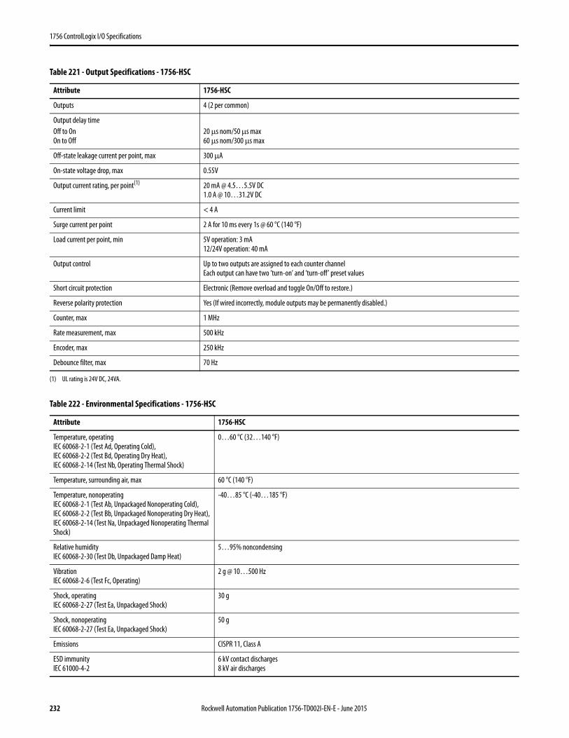
1756 ControlLogix I/O Specifications
Table 221 - Output Specifications - 1756-HSC
Attribute 1756-HSC
Outputs 4 (2 per common)
Output delay timeOff to OnOn to Off
20 μs nom/50 μs max60 μs nom/300 μs max
Off-state leakage current per point, max 300 μA
On-state voltage drop, max 0.55V
Output current rating, per point(1)
(1) UL rating is 24V DC, 24VA.
20 mA @ 4.5…5.5V DC1.0 A @ 10…31.2V DC
Current limit < 4 A
Surge current per point 2 A for 10 ms every 1s @ 60 °C (140 °F)
Load current per point, min 5V operation: 3 mA 12/24V operation: 40 mA
Output control Up to two outputs are assigned to each counter channelEach output can have two ’turn-on’ and ’turn-off’ preset values
Short circuit protection Electronic (Remove overload and toggle On/Off to restore.)
Reverse polarity protection Yes (If wired incorrectly, module outputs may be permanently disabled.)
Counter, max 1 MHz
Rate measurement, max 500 kHz
Encoder, max 250 kHz
Debounce filter, max 70 Hz
Table 222 - Environmental Specifications - 1756-HSC
Attribute 1756-HSC
Temperature, operatingIEC 60068-2-1 (Test Ad, Operating Cold),IEC 60068-2-2 (Test Bd, Operating Dry Heat),IEC 60068-2-14 (Test Nb, Operating Thermal Shock)
0…60 °C (32…140 °F)
Temperature, surrounding air, max 60 °C (140 °F)
Temperature, nonoperatingIEC 60068-2-1 (Test Ab, Unpackaged Nonoperating Cold),IEC 60068-2-2 (Test Bb, Unpackaged Nonoperating Dry Heat),IEC 60068-2-14 (Test Na, Unpackaged Nonoperating Thermal Shock)
-40…85 °C (-40…185 °F)
Relative humidityIEC 60068-2-30 (Test Db, Unpackaged Damp Heat)
5…95% noncondensing
VibrationIEC 60068-2-6 (Test Fc, Operating)
2 g @ 10…500 Hz
Shock, operatingIEC 60068-2-27 (Test Ea, Unpackaged Shock)
30 g
Shock, nonoperatingIEC 60068-2-27 (Test Ea, Unpackaged Shock)
50 g
Emissions CISPR 11, Class A
ESD immunityIEC 61000-4-2
6 kV contact discharges8 kV air discharges
232 Rockwell Automation Publication 1756-TD002I-EN-E - June 2015
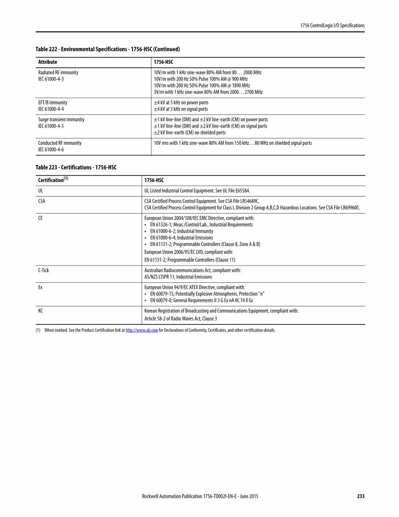
1756 ControlLogix I/O Specifications
Radiated RF immunityIEC 61000-4-3
10V/m with 1 kHz sine-wave 80% AM from 80… 2000 MHz10V/m with 200 Hz 50% Pulse 100% AM @ 900 MHz10V/m with 200 Hz 50% Pulse 100% AM @ 1890 MHz3V/m with 1 kHz sine-wave 80% AM from 2000…2700 MHz
EFT/B immunityIEC 61000-4-4
±4 kV at 5 kHz on power ports±4 kV at 5 kHz on signal ports
Surge transient immunityIEC 61000-4-5
±1 kV line-line (DM) and ±2 kV line-earth (CM) on power ports±1 kV line-line (DM) and ±2 kV line-earth (CM) on signal ports±2 kV line-earth (CM) on shielded ports
Conducted RF immunityIEC 61000-4-6
10V rms with 1 kHz sine-wave 80% AM from 150 kHz…80 MHz on shielded signal ports
Table 223 - Certifications - 1756-HSC
Certification(1)
(1) When marked. See the Product Certification link at http://www.ab.com for Declarations of Conformity, Certificates, and other certification details.
1756-HSC
UL UL Listed Industrial Control Equipment. See UL File E65584.
CSA CSA Certified Process Control Equipment. See CSA File LR54689C.CSA Certified Process Control Equipment for Class I, Division 2 Group A,B,C,D Hazardous Locations. See CSA File LR69960C.
CE European Union 2004/108/IEC EMC Directive, compliant with:• EN 61326-1; Meas./Control/Lab., Industrial Requirements• EN 61000-6-2; Industrial Immunity• EN 61000-6-4; Industrial Emissions• EN 61131-2; Programmable Controllers (Clause 8, Zone A & B)European Union 2006/95/EC LVD, compliant with:EN 61131-2; Programmable Controllers (Clause 11)
C-Tick Australian Radiocommunications Act, compliant with:AS/NZS CISPR 11; Industrial Emissions
Ex European Union 94/9/EC ATEX Directive, compliant with:• EN 60079-15; Potentially Explosive Atmospheres, Protection "n"• EN 60079-0; General Requirements II 3 G Ex nA IIC T4 X Gc
KC Korean Registration of Broadcasting and Communications Equipment, compliant with:Article 58-2 of Radio Waves Act, Clause 3
Table 222 - Environmental Specifications - 1756-HSC (Continued)
Attribute 1756-HSC
Rockwell Automation Publication 1756-TD002I-EN-E - June 2015 233
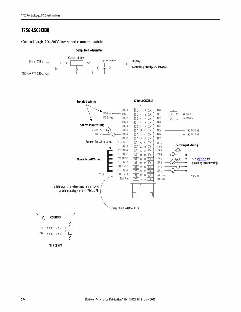
1756 ControlLogix I/O Specifications
1756-LSC8XIB8I
ControlLogix 10…30V low-speed counter module
1
3
5
7
01 9
21 11
41 31
61 51
81 71
02 91
22 12
42 32
62 52
82 72
03 92
23 13
43 33
63 53
(+)(+)
GND-0GND-1
GND-2
GND-3
CTR-GND-0
GND-4
GND-5
GND-6
GND-7
Not Used
CTR GND-1
CTR GND-2
CTR GND- 3
CTR GND-4
56
7
7
IN-0
IN-1
IN-2
IN-3
CTR-0
IN-4
IN-5
IN-6
IN-7
Not UsedNot Used
DC-5 (-)
DC (-)
DC-6 (-)DC-5 (+)DC-6 (+)
DC (+)
DC-1 (+)
DC-2 (+)
DC-1 (-)
DC-2 (-)
CTR GND-
CTR GND-
CTR GND-
CTR GND-
CTR-1 CTR-2
CTR-3
CTR-4
CTR-5
CTR-6
CTR-7
2
4
6
8
Simplified Schematic
1756-LSC8XIB8I
Daisy Chain to Other RTBs
Source Input Wiring
Jumper Bar Cut to Length
Nonisolated Wiring
Isolated Wiring
Sink Input Wiring
Additional jumper bars may be purchasedby using catalog number 1756-JMPR.
ControlLogix Backplane Interface
DisplayCurrent Limiter
COUNTER
PEER DEVICE
OK
GND-x or CTR GND-x
IN-x or CTR-x
0 1 2 3 4 5 6 7
ST
CTR
0 1 2 3 4 5 6 7
See page 235 for proximity sensor wiring.
Opto-isolator
234 Rockwell Automation Publication 1756-TD002I-EN-E - June 2015
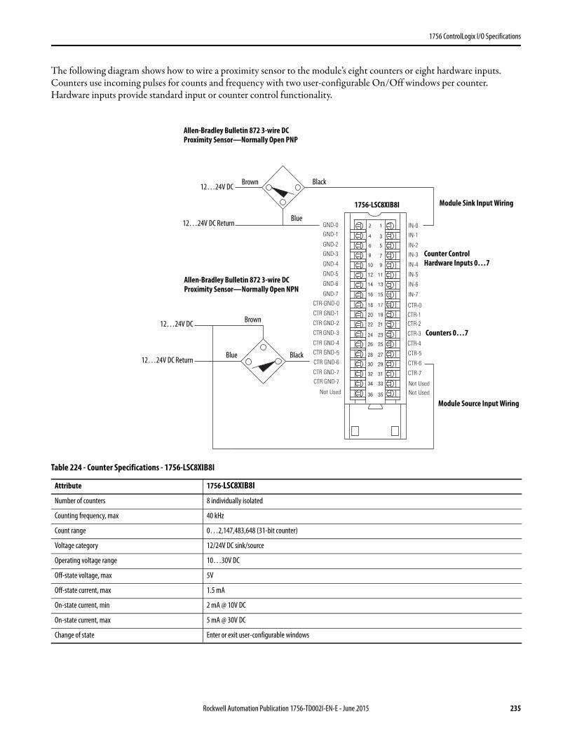
1756 ControlLogix I/O Specifications
The following diagram shows how to wire a proximity sensor to the module’s eight counters or eight hardware inputs. Counters use incoming pulses for counts and frequency with two user-configurable On/Off windows per counter. Hardware inputs provide standard input or counter control functionality.
Table 224 - Counter Specifications - 1756-LSC8XIB8I
Attribute 1756-LSC8XIB8I
Number of counters 8 individually isolated
Counting frequency, max 40 kHz
Count range 0…2,147,483,648 (31-bit counter)
Voltage category 12/24V DC sink/source
Operating voltage range 10…30V DC
Off-state voltage, max 5V
Off-state current, max 1.5 mA
On-state current, min 2 mA @ 10V DC
On-state current, max 5 mA @ 30V DC
Change of state Enter or exit user-configurable windows
1
3
5
7
01 9
21 11
41 31
61 51
81 71
02 91
22 12
42 32
62 52
82 72
03 92
23 13
43 33
63 53
GND-0GND-1
GND-2
GND-3
CTR-GND-0
GND-4
GND-5
GND-6
GND-7
Not Used
CTR GND-1
CTR GND-2
CTR GND- 3
CTR GND-4
56
7
7
IN-0
IN-1
IN-2
IN-3
CTR-0
IN-4
IN-5
IN-6
IN-7
Not UsedNot Used
CTR GND-
CTR GND-
CTR GND-
CTR GND-
CTR-1 CTR-2
CTR-3
CTR-4
CTR-5
CTR-6
CTR-7
2
4
6
8
Black
Blue
12…24V DC
12…24V DC Return
Brown
1756-LSC8XIB8I
Counter Control Hardware Inputs 0…7
Counters 0…7
Allen-Bradley Bulletin 872 3-wire DC Proximity Sensor—Normally Open NPN
Allen-Bradley Bulletin 872 3-wire DC Proximity Sensor—Normally Open PNP
BlackBlue12…24V DC Return
Brown
Module Sink Input Wiring
Module Source Input Wiring
12…24V DC
Rockwell Automation Publication 1756-TD002I-EN-E - June 2015 235

1756 ControlLogix I/O Specifications
Table 225 - Hardware Input Specifications - 1756-LSC8XIB8I
Attribute 1756-LSC8XIB8I
Inputs 8 individually isolated, standard input or counter control functionality
Voltage category 12/24V DC sink/source
Operating voltage range 10…30V DC
Input voltage, nom 24V DC
Input delay time (screw to backplane)Off to OnOn to Off
14 μs nom/23 μs max + user-configurable filter time of 0…30,000 μs14 μs nom/23 μs max + user-configurable filter time of 0…30,000 μs
Off-state voltage, max 5V
Off-state current, max 1.5 mA
On-state current, min 2 mA @ 10V DC
On-state current, max 5 mA @ 30V DC
Change of state Any transition
Table 226 - Module Specifications - 1756-LSC8XIB8I
Attribute 1756-LSC8XIB8I
Current draw @ 5.1V 275 mA
Current draw @ 24V 3 mA
Total backplane power 1.47 W
Power dissipation 3.8 W @ 60 °C (140 °F)
Thermal dissipation 12.97 BTU/hr
Input impedance, max 6 k Ω @ 30V DC
Cyclic update time 200 μs…750 ms
Isolation voltage 250V (continuous), reinforced insulation type, inputs-to-backplane250V (continuous), basic insulation type, input-to-inputType tested @ 2300V AC for 60 s inputs-to-backplaneType tested @ 1500V AC for 60 s input-to-input
Module keying Electronic, software configurable
Removable terminal block housing 1756-TBCH1756-TBS6H
RTB keying User-defined mechanical
Slot width 1
Wire category 1 on signal ports(1)
(1) Use this conductor category information for planning conductor routing as described in the system-level installation manual. See the Industrial Automation Wiring and Grounding Guidelines, publication 1770-4.1.
North American temperature code T4A
IEC temperature code T4
Enclosure type None (open-style)
Reverse polarity protection Yes
236 Rockwell Automation Publication 1756-TD002I-EN-E - June 2015
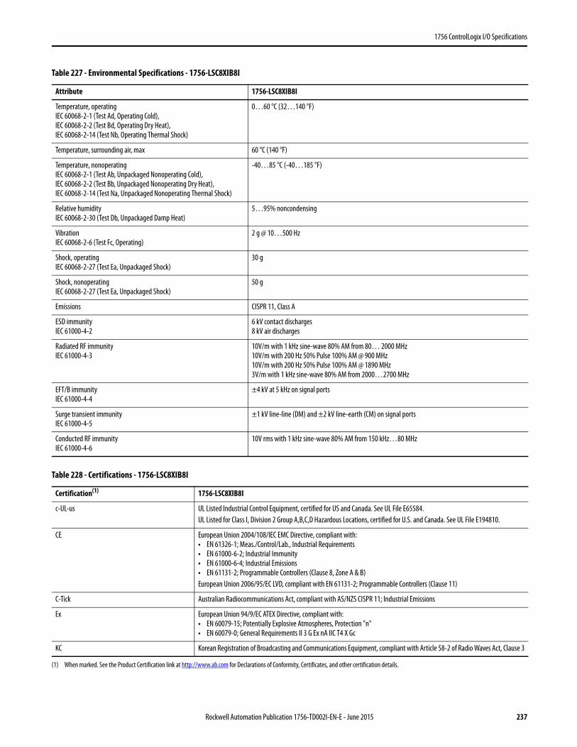
1756 ControlLogix I/O Specifications
Table 227 - Environmental Specifications - 1756-LSC8XIB8I
Attribute 1756-LSC8XIB8I
Temperature, operatingIEC 60068-2-1 (Test Ad, Operating Cold),IEC 60068-2-2 (Test Bd, Operating Dry Heat),IEC 60068-2-14 (Test Nb, Operating Thermal Shock)
0…60 °C (32…140 °F)
Temperature, surrounding air, max 60 °C (140 °F)
Temperature, nonoperatingIEC 60068-2-1 (Test Ab, Unpackaged Nonoperating Cold),IEC 60068-2-2 (Test Bb, Unpackaged Nonoperating Dry Heat),IEC 60068-2-14 (Test Na, Unpackaged Nonoperating Thermal Shock)
-40…85 °C (-40…185 °F)
Relative humidityIEC 60068-2-30 (Test Db, Unpackaged Damp Heat)
5…95% noncondensing
VibrationIEC 60068-2-6 (Test Fc, Operating)
2 g @ 10…500 Hz
Shock, operatingIEC 60068-2-27 (Test Ea, Unpackaged Shock)
30 g
Shock, nonoperatingIEC 60068-2-27 (Test Ea, Unpackaged Shock)
50 g
Emissions CISPR 11, Class A
ESD immunityIEC 61000-4-2
6 kV contact discharges8 kV air discharges
Radiated RF immunityIEC 61000-4-3
10V/m with 1 kHz sine-wave 80% AM from 80… 2000 MHz10V/m with 200 Hz 50% Pulse 100% AM @ 900 MHz10V/m with 200 Hz 50% Pulse 100% AM @ 1890 MHz3V/m with 1 kHz sine-wave 80% AM from 2000…2700 MHz
EFT/B immunityIEC 61000-4-4
±4 kV at 5 kHz on signal ports
Surge transient immunityIEC 61000-4-5
±1 kV line-line (DM) and ±2 kV line-earth (CM) on signal ports
Conducted RF immunityIEC 61000-4-6
10V rms with 1 kHz sine-wave 80% AM from 150 kHz…80 MHz
Table 228 - Certifications - 1756-LSC8XIB8I
Certification(1)
(1) When marked. See the Product Certification link at http://www.ab.com for Declarations of Conformity, Certificates, and other certification details.
1756-LSC8XIB8I
c-UL-us UL Listed Industrial Control Equipment, certified for US and Canada. See UL File E65584.UL Listed for Class I, Division 2 Group A,B,C,D Hazardous Locations, certified for U.S. and Canada. See UL File E194810.
CE European Union 2004/108/IEC EMC Directive, compliant with:• EN 61326-1; Meas./Control/Lab., Industrial Requirements• EN 61000-6-2; Industrial Immunity• EN 61000-6-4; Industrial Emissions• EN 61131-2; Programmable Controllers (Clause 8, Zone A & B)European Union 2006/95/EC LVD, compliant with EN 61131-2; Programmable Controllers (Clause 11)
C-Tick Australian Radiocommunications Act, compliant with AS/NZS CISPR 11; Industrial Emissions
Ex European Union 94/9/EC ATEX Directive, compliant with:• EN 60079-15; Potentially Explosive Atmospheres, Protection "n"• EN 60079-0; General Requirements II 3 G Ex nA IIC T4 X Gc
KC Korean Registration of Broadcasting and Communications Equipment, compliant with Article 58-2 of Radio Waves Act, Clause 3
Rockwell Automation Publication 1756-TD002I-EN-E - June 2015 237

1756 ControlLogix I/O Specifications
1756-PLS
ControlLogix programmable limit switch module
The 1756-PLS module supports enhanced packaging applications. The module requires three contiguous slots in the chassis.
+
_
+
_
OUTPUT 0
OUTPUT 1
OUTPUT 2
OUTPUT 3
DC PWR 0...3
INPUT 1
INPUT 0
OUTPUT 4
OUTPUT 7
DC PWR 4...7
OUTPUT 5
OUTPUT 6
INPUT 2
INPUT 3
INPUT 4
INPUT 5
INPUT 6
INPUT 7
DC COM 4-...7
12
34
56
78
910
1112
1314
1516
1718
1920
10...30V DCDC COM 0...3
+
_
OUTPUT 8
OUTPUT 9
OUTPUT 10
OUTPUT 11
DC PWR 8...11
INPUT 9
INPUT 8
OUTPUT 12
OUTPUT 15
DC PWR 12...15
OUTPUT 13
OUTPUT 14
INPUT 10
INPUT 11
INPUT 12
INPUT 13
INPUT 14
INPUT 15
DC COM 12...15
12
34
56
78
910
1112
1314
1516
1718
1920
DC COM 8...11
1756-PLS Inputs—Left Side 1756-PLS Outputs—Right Side
Do Not Use
Sine +
Sine –
Cosine +
Cosine –
12
34
56
78
910
1112
1314
1516
1718
1920
Allen-Bradley Resolver 846-SJDA1CG-R3-C
F (S3)
D (S1)
E (S2)
G (S4)
A (R1)
B (R2)
Reference +
Reference –
Do Not Use
Do Not Use
Do Not Use
Do Not Use
Do Not Use
Do Not Use
Do Not Use
Do Not Use
Do Not Use
Do Not Use
Do Not Use
Do Not Use
Do Not Use
1756-PLS Resolver
238 Rockwell Automation Publication 1756-TD002I-EN-E - June 2015
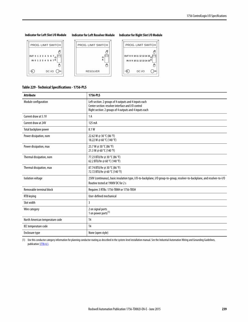
1756 ControlLogix I/O Specifications
Table 229 - Technical Specifications - 1756-PLS
Attribute 1756-PLS
Module configuration Left section: 2 groups of 4 outputs and 4 inputs eachCenter section: resolver interface and I/O controlRight section: 2 groups of 4 outputs and 4 inputs each
Current draw at 5.1V 1 A
Current draw at 24V 125 mA
Total backplane power 8.1 W
Power dissipation, nom 22.62 W @ 30 °C (86 °F)18.22 W @ 60 °C (140 °F)
Power dissipation, max 25.7 W @ 30 °C (86 °F)21.3 W @ 60 °C (140 °F)
Thermal dissipation, nom 77.23 BTU/hr @ 30 °C (86 °F)62.2 BTU/hr @ 60 °C (140 °F)
Thermal dissipation, max 87.74 BTU/hr @ 30 °C (86 °F)72.72 BTU/hr @ 60 °C (140 °F)
Isolation voltage 250V (continuous), basic insulation type, I/O-to-backplane, I/O group-to-group, resolver-to-backplane, and resolver-to-I/ORoutine tested at 1900V DC for 2 s
Removable terminal block Requires 3 RTBs: 1756-TBNH or 1756-TBSH
RTB keying User-defined mechanical
Slot width 3
Wire category 2 on signal ports1 on power ports(1)
(1) Use this conductor category information for planning conductor routing as described in the system-level installation manual. See the Industrial Automation Wiring and Grounding Guidelines, publication 1770-4.1.
North American temperature code T4
IEC temperature code T4
Enclosure type None (open style)
OK
0 OK
31 42 5 6 7
0 31 42 5 6 7
OUT
IN
PROG. LIMIT SWITCHPROG. LIMIT SWITCH
REVLOSERO/I CD
8 OK
119 1210 13 14 15OUT
IN
PROG. LIMIT SWITCH
DC I/O
8 119 1210 13 14 15
Indicator for Left Slot I/O Module Indicator for Left Resolver Module Indicator for Right Slot I/O Module
Rockwell Automation Publication 1756-TD002I-EN-E - June 2015 239
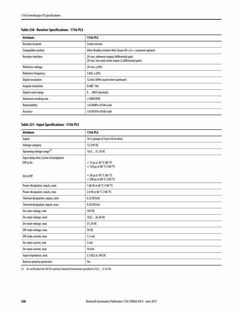
1756 ControlLogix I/O Specifications
Table 230 - Resolver Specifications - 1756-PLS
Attribute 1756-PLS
Resolver location Center section
Compatible resolver Allen-Bradley resolver 846-SJxxxx-R3-x (x = customer options)
Resolver interface 2V rms, reference output (differential pair)2V rms, sine and cosine inputs (2 differential pairs)
Reference voltage 2V rms ±20%
Reference frequency 5 kHz ±20%
Digital resolution 12 bits (4096 counts from hardware)
Angular resolution 0.088 °/bit
Digital count range 0…4095 (decimal)
Maximum tracking rate ±1800 RPM
Repeatability ±0.0488% of full scale
Accuracy ±0.0976% of full scale
Table 231 - Input Specifications - 1756-PLS
Attribute 1756-PLS
Inputs 16 (2 groups of 4 per I/O section)
Voltage category 12/24V DC
Operating voltage range(1)
(1) UL certification for 24V DC nominal. Rockwell Automation specified to 10.8…31.2V DC.
10.8…31.2V DC
Input delay time (screw to backplane)Off to On
On to Off
< 15 μs @ 30 °C (86 °F)< 150 μs @ 60 °C (140 °F)
< 30 μs @ 30 °C (86 °F)< 200 μs @ 60 °C (140 °F)
Power dissipation, inputs, nom 1.86 W @ 60 °C (140 °F)
Power dissipation, inputs, max 2.8 W @ 60 °C (140 °F)
Thermal dissipation, inputs, nom 6.35 BTU/hr
Thermal dissipation, inputs, max 9.56 BTU/hr
On-state voltage, min 10V DC
On-state voltage, nom 10.8…26.4V DC
On-state voltage, max 31.2V DC
Off-state voltage, max 5V DC
Off-state current, max 1.5 mA
On-state current, min 3 mA
On-state current, max 10 mA
Input impedance, max 3.3 kΩ @ 24V DC
Reverse polarity protection Yes
240 Rockwell Automation Publication 1756-TD002I-EN-E - June 2015
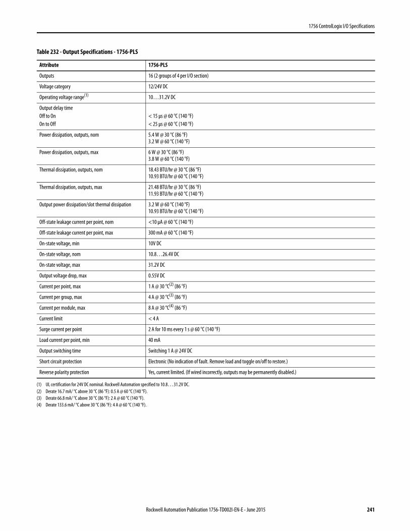
1756 ControlLogix I/O Specifications
Table 232 - Output Specifications - 1756-PLS
Attribute 1756-PLS
Outputs 16 (2 groups of 4 per I/O section)
Voltage category 12/24V DC
Operating voltage range(1)
(1) UL certification for 24V DC nominal. Rockwell Automation specified to 10.8…31.2V DC.
10…31.2V DC
Output delay timeOff to OnOn to Off
< 15 μs @ 60 °C (140 °F) < 25 μs @ 60 °C (140 °F)
Power dissipation, outputs, nom 5.4 W @ 30 °C (86 °F)3.2 W @ 60 °C (140 °F)
Power dissipation, outputs, max 6 W @ 30 °C (86 °F)3.8 W @ 60 °C (140 °F)
Thermal dissipation, outputs, nom 18.43 BTU/hr @ 30 °C (86 °F)10.93 BTU/hr @ 60 °C (140 °F)
Thermal dissipation, outputs, max 21.48 BTU/hr @ 30 °C (86 °F)11.93 BTU/hr @ 60 °C (140 °F)
Output power dissipation/slot thermal dissipation 3.2 W @ 60 °C (140 °F)10.93 BTU/hr @ 60 °C (140 °F)
Off-state leakage current per point, nom <10 μA @ 60 °C (140 °F)
Off-state leakage current per point, max 300 mA @ 60 °C (140 °F)
On-state voltage, min 10V DC
On-state voltage, nom 10.8…26.4V DC
On-state voltage, max 31.2V DC
Output voltage drop, max 0.55V DC
Current per point, max 1 A @ 30 °C(2) (86 °F)
(2) Derate 16.7 mA/ °C above 30 °C (86 °F): 0.5 A @ 60 °C (140 °F).
Current per group, max 4 A @ 30 °C(3) (86 °F)
(3) Derate 66.8 mA/ °C above 30 °C (86 °F): 2 A @ 60 °C (140 °F).
Current per module, max 8 A @ 30 °C(4) (86 °F)
(4) Derate 133.6 mA/ °C above 30 °C (86 °F): 4 A @ 60 °C (140 °F).
Current limit < 4 A
Surge current per point 2 A for 10 ms every 1 s @ 60 °C (140 °F)
Load current per point, min 40 mA
Output switching time Switching 1 A @ 24V DC
Short circuit protection Electronic (No indication of fault. Remove load and toggle on/off to restore.)
Reverse polarity protection Yes, current limited. (If wired incorrectly, outputs may be permanently disabled.)
Rockwell Automation Publication 1756-TD002I-EN-E - June 2015 241
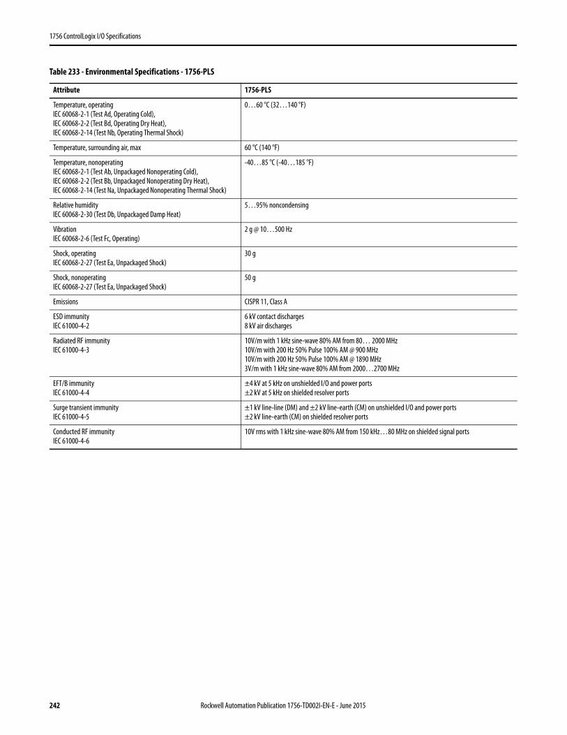
1756 ControlLogix I/O Specifications
Table 233 - Environmental Specifications - 1756-PLS
Attribute 1756-PLS
Temperature, operatingIEC 60068-2-1 (Test Ad, Operating Cold),IEC 60068-2-2 (Test Bd, Operating Dry Heat),IEC 60068-2-14 (Test Nb, Operating Thermal Shock)
0…60 °C (32…140 °F)
Temperature, surrounding air, max 60 °C (140 °F)
Temperature, nonoperatingIEC 60068-2-1 (Test Ab, Unpackaged Nonoperating Cold),IEC 60068-2-2 (Test Bb, Unpackaged Nonoperating Dry Heat),IEC 60068-2-14 (Test Na, Unpackaged Nonoperating Thermal Shock)
-40…85 °C (-40…185 °F)
Relative humidityIEC 60068-2-30 (Test Db, Unpackaged Damp Heat)
5…95% noncondensing
VibrationIEC 60068-2-6 (Test Fc, Operating)
2 g @ 10…500 Hz
Shock, operatingIEC 60068-2-27 (Test Ea, Unpackaged Shock)
30 g
Shock, nonoperatingIEC 60068-2-27 (Test Ea, Unpackaged Shock)
50 g
Emissions CISPR 11, Class A
ESD immunityIEC 61000-4-2
6 kV contact discharges8 kV air discharges
Radiated RF immunityIEC 61000-4-3
10V/m with 1 kHz sine-wave 80% AM from 80… 2000 MHz10V/m with 200 Hz 50% Pulse 100% AM @ 900 MHz10V/m with 200 Hz 50% Pulse 100% AM @ 1890 MHz3V/m with 1 kHz sine-wave 80% AM from 2000…2700 MHz
EFT/B immunityIEC 61000-4-4
±4 kV at 5 kHz on unshielded I/O and power ports±2 kV at 5 kHz on shielded resolver ports
Surge transient immunityIEC 61000-4-5
±1 kV line-line (DM) and ±2 kV line-earth (CM) on unshielded I/O and power ports±2 kV line-earth (CM) on shielded resolver ports
Conducted RF immunityIEC 61000-4-6
10V rms with 1 kHz sine-wave 80% AM from 150 kHz…80 MHz on shielded signal ports
242 Rockwell Automation Publication 1756-TD002I-EN-E - June 2015
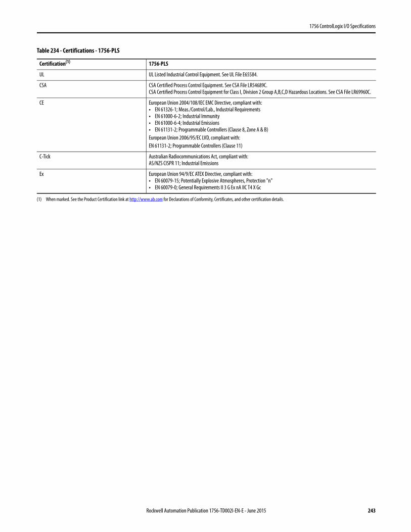
1756 ControlLogix I/O Specifications
Table 234 - Certifications - 1756-PLS
Certification(1) 1756-PLS
UL UL Listed Industrial Control Equipment. See UL File E65584.
CSA CSA Certified Process Control Equipment. See CSA File LR54689C.CSA Certified Process Control Equipment for Class I, Division 2 Group A,B,C,D Hazardous Locations. See CSA File LR69960C.
CE European Union 2004/108/IEC EMC Directive, compliant with:• EN 61326-1; Meas./Control/Lab., Industrial Requirements• EN 61000-6-2; Industrial Immunity• EN 61000-6-4; Industrial Emissions• EN 61131-2; Programmable Controllers (Clause 8, Zone A & B)European Union 2006/95/EC LVD, compliant with:EN 61131-2; Programmable Controllers (Clause 11)
C-Tick Australian Radiocommunications Act, compliant with:AS/NZS CISPR 11; Industrial Emissions
Ex European Union 94/9/EC ATEX Directive, compliant with:• EN 60079-15; Potentially Explosive Atmospheres, Protection "n"• EN 60079-0; General Requirements II 3 G Ex nA IIC T4 X Gc
(1) When marked. See the Product Certification link at http://www.ab.com for Declarations of Conformity, Certificates, and other certification details.
Rockwell Automation Publication 1756-TD002I-EN-E - June 2015 243
1756 ControlLogix I/O Specifications
ControlLogix I/O Accessories
Place 1756 I/O modules in any slot in a 1756 chassis. Each chassis requires a power supply.
• For more information on chassis specifications, see ControlLogix Chassis Specifications Technical Data, publication 1756-TD006.
• For more information on power supply specifications, see ControlLogix Power Supply Specifications Technical Data, publication 1756-TD005.
• For more information on choosing the right power supply for your application, see the additional product documentation, for example, a user manual, for your 1756 ControlLogix I/O module.
Product Cat. No.
Chassis 1756-A4, 1756-A7, 1756-A10, 1756-A13, 1756-A17
Power supply, standard 1756-PA72/C, 1756-PA75/B, 1756-PB72/C, 1756-PB75/B, 1756-PC75/B, 1756-PH75/B
Power supply, redundant 1756-PA75R, 1756-PB75R, 1756-PSCA21756-CPR2 cable
244 Rockwell Automation Publication 1756-TD002I-EN-E - June 2015
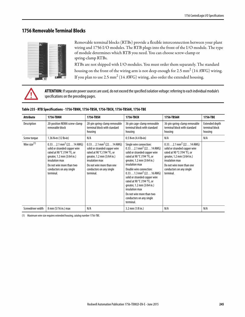
1756 ControlLogix I/O Specifications
1756 Removable Terminal Blocks
Removable terminal blocks (RTBs) provide a flexible interconnection between your plant wiring and 1756 I/O modules. The RTB plugs into the front of the I/O module. The type of module determines which RTB you need. You can choose screw-clamp or spring-clamp RTBs.RTBs are not shipped with I/O modules. You must order them separately. The standard housing on the front of the wiring arm is not deep enough for 2.5 mm2 (14 AWG) wiring. If you plan to use 2.5 mm2 (14 AWG) wiring, also order the extended housing.
ATTENTION: If separate power sources are used, do not exceed the specified isolation voltage: referring to each individual module’s specifications on the preceding pages.
Table 235 - RTB Specifications - 1756-TBNH, 1756-TBSH, 1756-TBCH, 1756-TBS6H, 1756-TBE
Attribute 1756-TBNH 1756-TBSH 1756-TBCH 1756-TBS6H 1756-TBE
Description 20-position NEMA screw-clamp removable block
20-pin spring-clamp removable terminal block with standard housing
36-pin cage-clamp removable terminal block with standard housing
36-pin spring-clamp removable terminal block with standard housing
Extended depth terminal block housing
Screw torque 1.36 N•m (12 lb•in) N/A 0.5 N•m (4.4 lb•in) N/A N/A
Wire size(1)
(1) Maximum wire size requires extended housing, catalog number 1756-TBE.
0.33…2.1 mm2 (22…14 AWG) solid or stranded copper wire rated at 90 °C (194 °F), or greater, 1.2 mm (3/64 in.) insulation maxDo not wire more than two conductors on any single terminal.
0.33…2.1 mm2 (22…14 AWG) solid or stranded copper wire rated at 90 °C (194 °F), or greater, 1.2 mm (3/64 in.) insulation maxDo not wire more than one conductors on any single terminal.
Single wire connection: 0.33…2.1 mm2 (22…14 AWG) solid or stranded copper wire rated at 90 °C (194 °F), or greater, 1.2 mm (3/64 in.) insulation maxDouble wire connection: 0.33…1.3 mm2 (22…16 AWG) solid or stranded copper wire rated at 90 °C (194 °F), or greater, 1.2 mm (3/64 in.) insulation maxDo not wire more than two conductors on any single terminal.
0.33…2.1 mm2 (22…14 AWG) solid or stranded copper wire rated at 90 °C (194 °F), or greater, 1.2 mm (3/64 in.) insulation maxDo not wire more than one conductors on any single terminal.
Screwdriver width 8 mm (5/16 in.) max N/A 3.2 mm (1/8 in.) N/A N/A
Rockwell Automation Publication 1756-TD002I-EN-E - June 2015 245
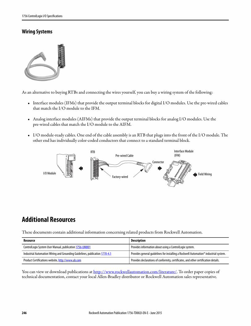
1756 ControlLogix I/O Specifications
Wiring Systems
As an alternative to buying RTBs and connecting the wires yourself, you can buy a wiring system of the following:
• Interface modules (IFMs) that provide the output terminal blocks for digital I/O modules. Use the pre-wired cables that match the I/O module to the IFM.
• Analog interface modules (AIFMs) that provide the output terminal blocks for analog I/O modules. Use the pre-wired cables that match the I/O module to the AIFM.
• I/O module-ready cables. One end of the cable assembly is an RTB that plugs into the front of the I/O module. The other end has individually color-coded conductors that connect to a standard terminal block.
Additional Resources
These documents contain additional information concerning related products from Rockwell Automation.
You can view or download publications at http://www.rockwellautomation.com/literature/. To order paper copies of technical documentation, contact your local Allen-Bradley distributor or Rockwell Automation sales representative.
Resource Description
ControlLogix System User Manual, publication 1756-UM001 Provides information about using a ControlLogix system.
Industrial Automation Wiring and Grounding Guidelines, publication 1770-4.1 Provides general guidelines for installing a Rockwell Automation® industrial system.
Product Certifications website, http://www.ab.com Provides declarations of conformity, certificates, and other certification details.
RTB
I/O ModuleFactory-wired
Pre-wired Cable
Connector
Interface Module (IFM)
Field Wiring
246 Rockwell Automation Publication 1756-TD002I-EN-E - June 2015
1756 ControlLogix I/O Specifications
Notes:
Rockwell Automation Publication 1756-TD002I-EN-E - June 2015 247
Allen-Bradley, ControlLogix, RSLogix, Rockwell Software, Rockwell Automation, and LISTEN. THINK. SOLVE are trademarks of Rockwell Automation, Inc.
Trademarks not belonging to Rockwell Automation are property of their respective companies.
Publication 1756-TD002I-EN-E - June 2015 Supersedes Publication 1756-TD002H-EN-E - December 2014 Copyright © 2015 Rockwell Automation, Inc. All rights reserved. Printed in the U.S.A.
Rockwell Automation Support
Rockwell Automation provides technical information on the Web to assist you in using its products.At http://www.rockwellautomation.com/support you can find technical and application notes, sample code, and links to software service packs. You can also visit our Support Center at https://rockwellautomation.custhelp.com/ for software updates, support chats and forums, technical information, FAQs, and to sign up for product notification updates.
In addition, we offer multiple support programs for installation, configuration, and troubleshooting. For more information, contact your local distributor or Rockwell Automation representative, or visithttp://www.rockwellautomation.com/services/online-phone.
Installation Assistance
If you experience a problem within the first 24 hours of installation, review the information that is contained in this manual. You can contact Customer Support for initial help in getting your product up and running.
New Product Satisfaction Return
Rockwell Automation tests all of its products to help ensure that they are fully operational when shipped from the manufacturing facility. However, if your product is not functioning and needs to be returned, follow these procedures.
Documentation Feedback
Your comments will help us serve your documentation needs better. If you have any suggestions on how to improve this document, complete this form, publication RA-DU002, available at http://www.rockwellautomation.com/literature/.
United States or Canada 1.440.646.3434
Outside United States or Canada Use the Worldwide Locator at http://www.rockwellautomation.com/rockwellautomation/support/overview.page, or contact your local Rockwell Automation representative.
United States Contact your distributor. You must provide a Customer Support case number (call the phone number above to obtain one) to your distributor to complete the return process.
Outside United States Please contact your local Rockwell Automation representative for the return procedure.
Rockwell Otomasyon Ticaret A.Ş., Kar Plaza İş Merkezi E Blok Kat:6 34752 İçerenköy, İstanbul, Tel: +90 (216) 5698400
Rockwell Automation maintains current product environmental information on its website athttp://www.rockwellautomation.com/rockwellautomation/about-us/sustainability-ethics/product-environmental-compliance.page.