
1747-2.37, DH-485/RS-232C Interface Module, Product Data · •By providing a modem connection into...
14
-
Upload
nguyenkien -
Category
Documents
-
view
219 -
download
0
Transcript of 1747-2.37, DH-485/RS-232C Interface Module, Product Data · •By providing a modem connection into...
Product Data
DH�485/RS�232C Interface Module
2
The interface module can enhance your SLC 500 application with thefollowing features:
• It can provide you with local or remote access to examine ladderprograms, monitor program operation, and make changes if necessary.
• By providing a modem connection into your DH-485 network, it makestroubleshooting installations over the telephone lines possible.
• It is ideally suited for SCADA/RTU applications where point-to-pointcommunication is required.
• It has a configuration and a DF1 serial port that each accommodatesRS-232/423, RS-422, and RS-485 communications.
• It is easily configured using either backplane communication or an ASCIIterminal, and it installs directly into the SLC 500 chassis.
• It has a Real Time Clock that can be used by the SLC processor inconjunction with normal operation.
• It allows communication from a DH-485 network device to a single DF1device.
What's Inside... Page
Module Overview 3
Typical Applications 8
Allen-Bradley Support 11
Specifications 12
Benefits
Product Data
DH�485/RS�232C Interface Module
3
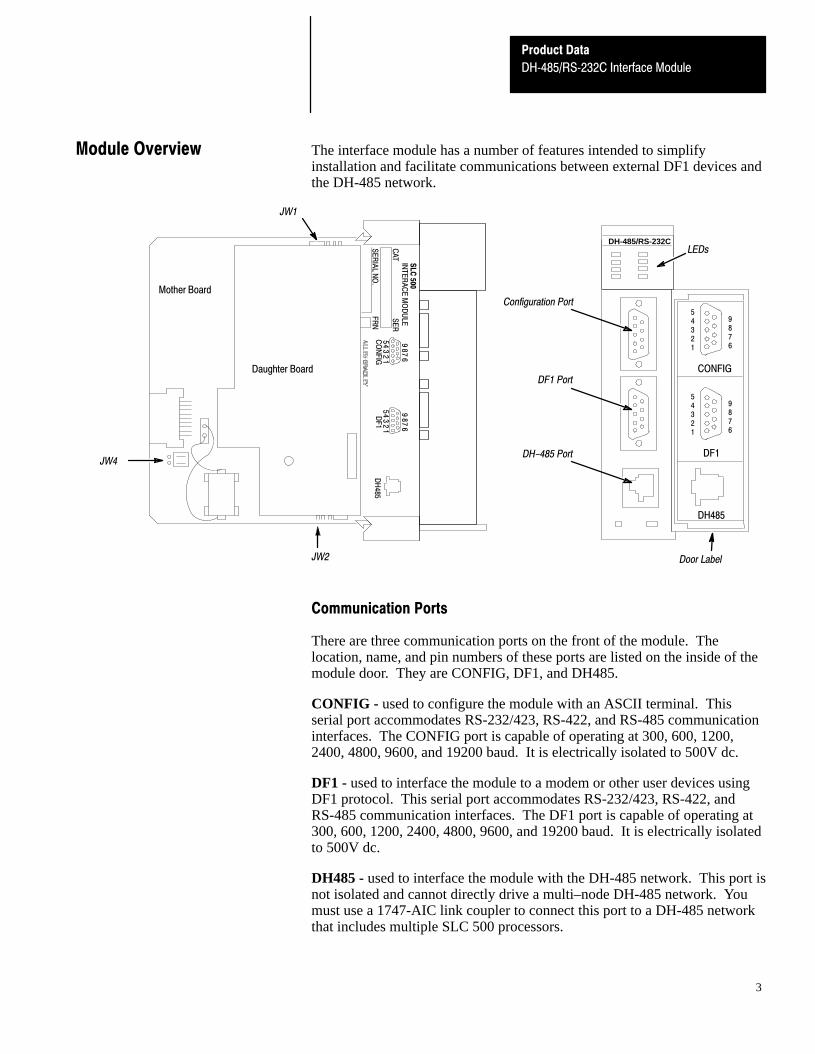
The interface module has a number of features intended to simplifyinstallation and facilitate communications between external DF1 devices andthe DH-485 network.
DH-485/RS-232C
JW4
JW1
JW2
SL
C 500
INT
ER
AC
E M
OD
ULE
CA
TS
ER
SE
RIA
L NO
.F
RN
12
34
5
67
89
CO
NF
IG1
23
45
67
89D
F1
DH
485
Mother Board
Daughter Board CONFIG
54321
9876
DF1
54321
9876
DH485
Configuration Port
DH-485 Port
DF1 Port
Door Label
LEDs
Communication Ports
There are three communication ports on the front of the module. Thelocation, name, and pin numbers of these ports are listed on the inside of themodule door. They are CONFIG, DF1, and DH485.
CONFIG - used to configure the module with an ASCII terminal. Thisserial port accommodates RS-232/423, RS-422, and RS-485 communicationinterfaces. The CONFIG port is capable of operating at 300, 600, 1200,2400, 4800, 9600, and 19200 baud. It is electrically isolated to 500V dc.
DF1 - used to interface the module to a modem or other user devices usingDF1 protocol. This serial port accommodates RS-232/423, RS-422, andRS-485 communication interfaces. The DF1 port is capable of operating at300, 600, 1200, 2400, 4800, 9600, and 19200 baud. It is electrically isolatedto 500V dc.
DH485 - used to interface the module with the DH-485 network. This port isnot isolated and cannot directly drive a multi–node DH-485 network. Youmust use a 1747-AIC link coupler to connect this port to a DH-485 networkthat includes multiple SLC 500 processors.
Module Overview
Product Data
DH�485/RS�232C Interface Module
4
The Catalog Number 1747-C10 or Catalog Number 1747-C13 cables canconnect the interface module’s DH485 port to a 1747-AIC link coupler. TheCatalog Number 1747-C13 cable can also connect the module’s DH485 portdirectly to a single SLC processor.
Modem Compatibility
The module can be connected to most types of dial-up network or directconnect modems.
Important: Some modems are designed to respond to the DTR signal byanswering the phone whether it is ringing or not. Since themodule asserts DTR at all times (except during the hang-upsequence), the phone appears to be busy at all times. Do notuse the interface module with any type of modem that answersthe phone as soon as DTR is asserted.
The type of modems you can use are:
• Manual – typically acoustically coupled modems. A person on each endof the phone line establishes the connection. They then insert thehandsets into an acoustic coupler to complete the connection.
• DTE Controlled Answer – these unattended modems are attacheddirectly to the phone lines. The interface module acts as the DataTerminal Equipment (DTE), which controls the modem via the DTR,DSR, and DCD signals. The module incorporates timeouts and tests toproperly operate these types of modems.
• Auto Answer – These modems have self-contained timeouts and tests.They can answer and hang up the phone automatically. The module hasno means of controlling an auto-dial modem, but it can be used inconjunction with a separate auto-dialer.
• Direct Connect – These modems connect to a dedicated, leased phoneline and remain active at all times.
Product Data
DH�485/RS�232C Interface Module
5
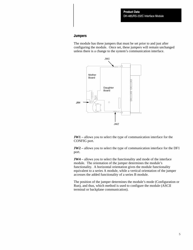
Jumpers
The module has three jumpers that must be set prior to and just afterconfiguring the module. Once set, these jumpers will remain unchangedunless there is a change to the system’s communication interface.
JW4
JW1
JW2
MotherBoard
DaughterBoard
JW1 – allows you to select the type of communication interface for theCONFIG port.
JW2 – allows you to select the type of communication interface for the DF1port.
JW4 – allows you to select the functionality and mode of the interfacemodule. The orientation of the jumper determines the module’sfunctionality. A horizontal orientation gives the module functionalityequivalent to a series A module, while a vertical orientation of the jumperaccesses the added functionality of a series B module.
The position of the jumper determines the module’s mode (Configuration orRun), and thus, which method is used to configure the module (ASCIIterminal or backplane communication).
Product Data
DH�485/RS�232C Interface Module
6
Configuring Options
To configure the module, you can either use backplane communication or anASCII Terminal.
Configuring through the Backplane
The interface module can be configured through backplane communicationusing any SLC fixed, 5/01 , 5/02 , or 5/03 processor.
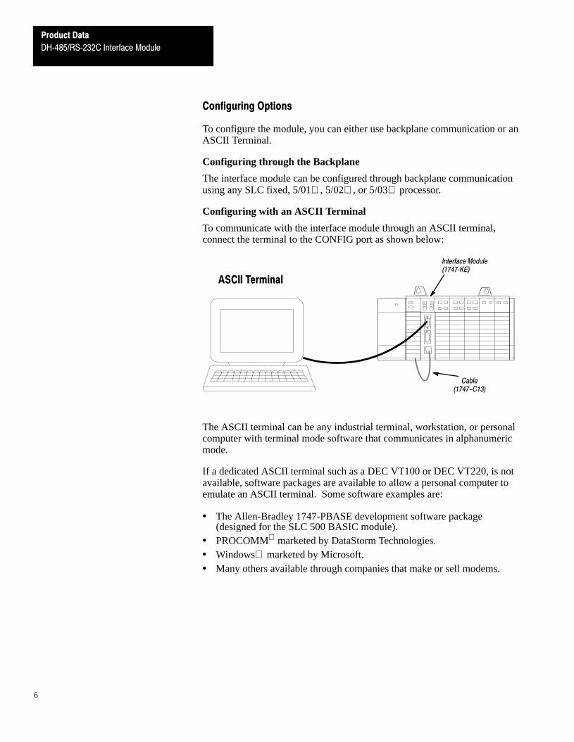
Configuring with an ASCII Terminal
To communicate with the interface module through an ASCII terminal,connect the terminal to the CONFIG port as shown below:
Interface Module(1747�KE)
ASCII Terminal
Cable(1747-C13)
The ASCII terminal can be any industrial terminal, workstation, or personalcomputer with terminal mode software that communicates in alphanumericmode.
If a dedicated ASCII terminal such as a DEC VT100 or DEC VT220, is notavailable, software packages are available to allow a personal computer toemulate an ASCII terminal. Some software examples are:
• The Allen-Bradley 1747-PBASE development software package(designed for the SLC 500 BASIC module).
• PROCOMM marketed by DataStorm Technologies.• Windows marketed by Microsoft.• Many others available through companies that make or sell modems.
Product Data
DH�485/RS�232C Interface Module
7
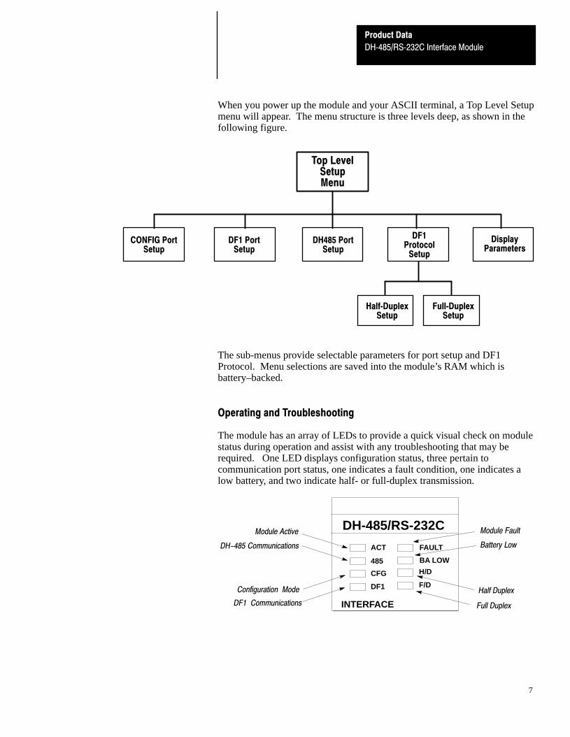
When you power up the module and your ASCII terminal, a Top Level Setupmenu will appear. The menu structure is three levels deep, as shown in thefollowing figure.
DF1Protocol
Setup
Half�DuplexSetup
Full�DuplexSetup
Top LevelSetupMenu
CONFIG PortSetup
DF1 PortSetup
DH485 PortSetup
DisplayParameters
The sub-menus provide selectable parameters for port setup and DF1Protocol. Menu selections are saved into the module’s RAM which isbattery–backed.
Operating and Troubleshooting
The module has an array of LEDs to provide a quick visual check on modulestatus during operation and assist with any troubleshooting that may berequired. One LED displays configuration status, three pertain tocommunication port status, one indicates a fault condition, one indicates alow battery, and two indicate half- or full-duplex transmission.
DH-485/RS-232C
ACT
485
CFG
DF1
FAULT
BA LOW
H/D
F/D
INTERFACE
DH-485 Communications
Configuration Mode
DF1 Communications
Module Fault
Battery Low
Half Duplex
Full Duplex
Module Active

Product Data
DH�485/RS�232C Interface Module
8
This section illustrates most typical applications for which the module issuited. A number of variations on these configurations is possible.
Modem
Modem
Interface Module(1747�KE)
Full�Duplex (Point�to�Point)
1747-C13
This configuration allows a connection to a single remote SLC node. The 1747�C13 cableeliminates the need for a 1747�AIC link coupler for connections to one node.
APS
Modem
Modem
LinkCoupler
LinkCoupler
Link Coupler(1747�AIC)
APS
Full�Duplex (Network, Example 1)
Interface Module(1747�KE)
This configuration allows connection to a remote DH�485 network of up to 31 SLC nodes.
1747-C10
1747-C13
Typical Applications
Product Data
DH�485/RS�232C Interface Module
9
Link Coupler(1747�AIC)
Modem
Modem
APS
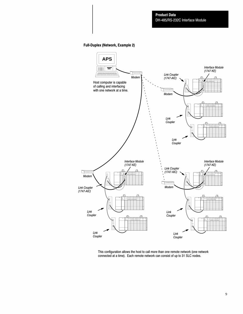
Full�Duplex (Network, Example 2)
LinkCoupler
LinkCoupler
LinkCoupler
LinkCoupler
LinkCoupler
LinkCoupler
Modem
Host computer is capableof calling and interfacingwith one network at a time.
Modem
Link Coupler(1747�AIC)
Interface Module(1747�KE)
Interface Module(1747�KE)
Interface Module(1747�KE)
Link Coupler(1747�AIC)
This configuration allows the host to call more than one remote network (one networkconnected at a time). Each remote network can consist of up to 31 SLC nodes.
Product Data
DH�485/RS�232C Interface Module
10
PLC-5/250
Modem
Modem
Interface Module(1747�KE)
LinkCoupler
LinkCoupler
Link Coupler(1747�AIC)
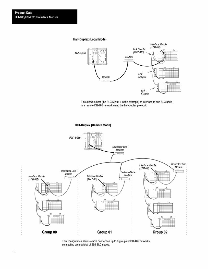
Half�Duplex (Local Mode)
This allows a host (the PLC 5/250 in this example) to interface to one SLC nodein a remote DH�485 network using the half�duplex protocol.
Group 02Group 01Group 00
PLC-5/250
Dedicated LineModem
Interface Module(1747�KE)
Interface Module(1747�KE)
Interface Module(1747�KE)
Half�Duplex (Remote Mode)
This configuration allows a host connection up to 8 groups of DH�485 networksconnecting up to a total of 255 SLC nodes.
Dedicated LineModem
Dedicated LineModem
Dedicated LineModem
Product Data
DH�485/RS�232C Interface Module
11
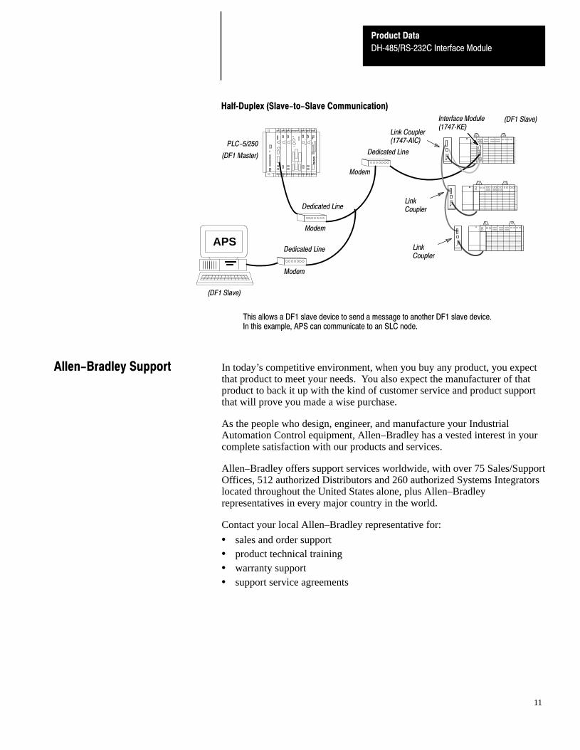
Half�Duplex (Slave-to-Slave Communication)
This allows a DF1 slave device to send a message to another DF1 slave device.In this example, APS can communicate to an SLC node.
PLC-5/250
Modem
Modem
Interface Module(1747�KE)
LinkCoupler
LinkCoupler
Link Coupler(1747�AIC)
APS
Modem
(DF1 Master)
(DF1 Slave)
(DF1 Slave)
Dedicated Line
Dedicated Line
Dedicated Line
In today’s competitive environment, when you buy any product, you expectthat product to meet your needs. You also expect the manufacturer of thatproduct to back it up with the kind of customer service and product supportthat will prove you made a wise purchase.
As the people who design, engineer, and manufacture your IndustrialAutomation Control equipment, Allen–Bradley has a vested interest in yourcomplete satisfaction with our products and services.
Allen–Bradley offers support services worldwide, with over 75 Sales/SupportOffices, 512 authorized Distributors and 260 authorized Systems Integratorslocated throughout the United States alone, plus Allen–Bradleyrepresentatives in every major country in the world.
Contact your local Allen–Bradley representative for:
• sales and order support• product technical training• warranty support• support service agreements
Allen-Bradley Support
Product Data
DH�485/RS�232C Interface Module
12
Module hardware specifications are listed in the following tables.
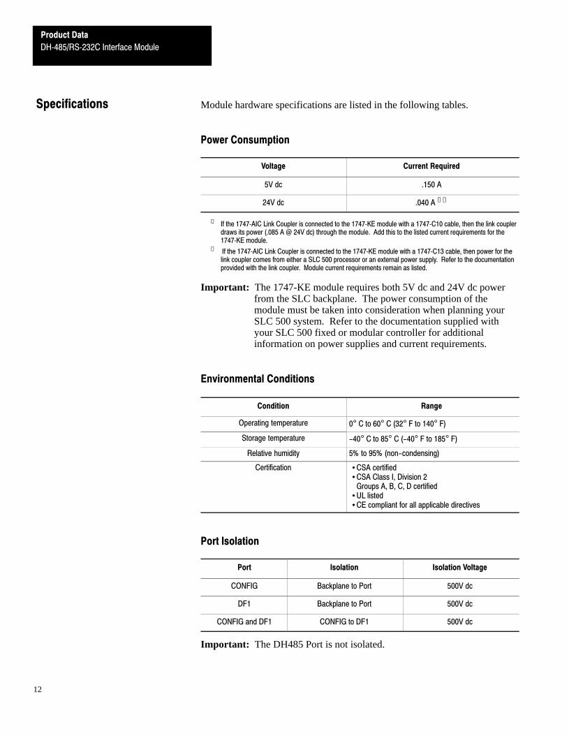
Power Consumption
Voltage Current Required
5V dc .150 A
24V dc .040 A ➀➁
➀ If the 1747�AIC Link Coupler is connected to the 1747�KE module with a 1747�C10 cable, then the link couplerdraws its power (.085 A @ 24V dc) through the module. Add this to the listed current requirements for the1747�KE module.
➁ If the 1747�AIC Link Coupler is connected to the 1747�KE module with a 1747�C13 cable, then power for thelink coupler comes from either a SLC 500 processor or an external power supply. Refer to the documentationprovided with the link coupler. Module current requirements remain as listed.
Important: The 1747-KE module requires both 5V dc and 24V dc powerfrom the SLC backplane. The power consumption of themodule must be taken into consideration when planning yourSLC 500 system. Refer to the documentation supplied withyour SLC 500 fixed or modular controller for additionalinformation on power supplies and current requirements.
Environmental Conditions
Condition Range
Operating temperature 0° C to 60° C (32° F to 140° F)
Storage temperature -40° C to 85° C (-40° F to 185° F)
Relative humidity 5% to 95% (non-condensing)
Certification • CSA certified• CSA Class I, Division 2
Groups A, B, C, D certified• UL listed• CE compliant for all applicable directives
Port Isolation
Port Isolation Isolation Voltage
CONFIG Backplane to Port 500V dc
DF1 Backplane to Port 500V dc
CONFIG and DF1 CONFIG to DF1 500V dc
Important: The DH485 Port is not isolated.
Specifications
Product Data
DH�485/RS�232C Interface Module
13
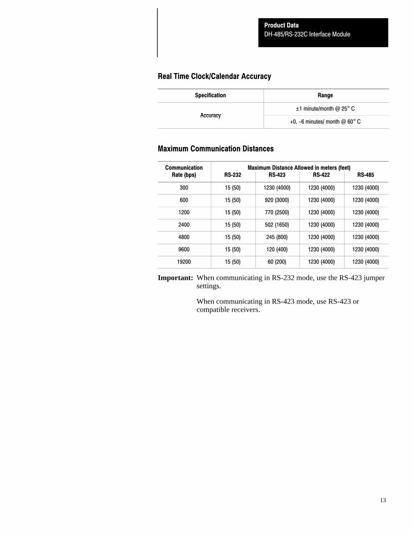
Real Time Clock/Calendar Accuracy
Specification Range
Accuracy±1 minute/month @ 25° C
Accuracy+0, -6 minutes/ month @ 60° C
Maximum Communication Distances
Communication Maximum Distance Allowed in meters (feet)Rate (bps) RS�232 RS�423 RS�422 RS�485
300 15 (50) 1230 (4000) 1230 (4000) 1230 (4000)
600 15 (50) 920 (3000) 1230 (4000) 1230 (4000)
1200 15 (50) 770 (2500) 1230 (4000) 1230 (4000)
2400 15 (50) 502 (1650) 1230 (4000) 1230 (4000)
4800 15 (50) 245 (800) 1230 (4000) 1230 (4000)
9600 15 (50) 120 (400) 1230 (4000) 1230 (4000)
19200 15 (50) 60 (200) 1230 (4000) 1230 (4000)
Important: When communicating in RS-232 mode, use the RS-423 jumpersettings.
When communicating in RS-423 mode, use RS-423 orcompatible receivers.


![Php module 1 - ttth dh khtn [khoahoclaptrinhweb.tin.vn]](https://static.fdocuments.net/doc/165x107/55b69d1ebb61eb5a0a8b4740/php-module-1-ttth-dh-khtn-khoahoclaptrinhwebtinvn.jpg)