
17205 Valves tech manual v9 - hvi.com.au Valves... · Valves TECHNICAL MANUAL 1 Disclaimer Please...
76
VALVES Technical Manual
Transcript of 17205 Valves tech manual v9 - hvi.com.au Valves... · Valves TECHNICAL MANUAL 1 Disclaimer Please...

V A L V E S
Technical Manual
WIREFRAME IMAGE OF BALL VALVE TO BE INSERTED - CURRENTLY AWAITING APPROVAL

Introduction 2
Valve Range Quick Reference Guide 2
Horizontal Float Valve 4 Introduction 4
Benefi ts 4
Standards & Tests 5
Operation and Installation Instructions 6
System Design Considerations 7
Chemical Resistance 8
Material & Components 9
Range & Dimensions 10
Sleeve Valves 12 Introduction 12
Benefi ts 12
Standards & Tests 13
Operation and Installation Instructions 14
System Design Considerations 15
Chemical Resistance 15
Material & Components 16
Range & Dimensions 17
Mark II Servo Tank Filling Valves 18 Introduction 18
Benefi ts 18
Standards & Tests 19
Operation and Installation Instructions 20
System Design Considerations 21
Chemical Resistance 21
Material & Components 22
Range & Dimensions 23
Cistern Valves 24 Introduction 24
Benefi ts 24
Standards & Tests 25
Operation and Installation Instructions 26
System Design Considerations 27
Chemical Resistance 27
Material & Components 28
Range & Dimensions 29
Blue Handled Ball Valves 30 Introduction 30
Benefi ts 30
Standards & Tests 31
Operation and Installation Instructions 32
System Design Considerations 33
Chemical Resistance 33
Material & Components 34
Range & Dimensions 35
Foot And Non-Return Valves 36 Introduction 36
Benefi ts 36
Standards & Tests 37
Operation and Installation Instructions 38
System Design Considerations 39
Chemical Resistance 39
Material & Components 40
Range & Dimensions 41
CONTENTS
Committed to sustainable development, Philmac is well renowned
for quality products and services. Philmac manufactures pipe fittings
and valves under a Quality Assurance System assessed and approved
to ISO 9001-2000 and has obtained the prestigious environmental
management certification ISO 14000. Philmac has a NATA accredited
laboratory and tests fittings and valves to international and national
standards. Third party accreditation is carried out by SAI Global.
NATA AccreditedLaboratoryNumber: 14673

Valves TECHNICAL MANUAL 1
Disclaimer
Please note that the information, opinions, recommendations and advice given in this manual are supplied only to provide an improved understanding of the technical aspects of fi tting systems.
So far as the law allows, Philmac Pty Ltd will not accept liability in respect of any loss or damage of any kind claimed to arise as a result of reliance upon any information claimed in this manual.
Please refer to our Terms and Conditions of sale.
Ratio Pressure Reducing Valves 42 Introduction 42
Benefi ts 42
Standards & Tests 43
Operation and Installation Instructions 44
System Design Considerations 46
Chemical Resistance 46
Material & Components 47
Range & Dimensions 48
Trough Valves 50 Introduction 50
Benefi ts 50
Standards & Tests 51
Operation and Installation Instructions 52
System Design Considerations 53
Chemical Resistance 53
Material & Components 54
Range & Dimensions 55
High Flow Float Valves 56 Introduction 56
Benefi ts 56
Standards & Tests 57
Operation and Installation Instructions 58
System Design Considerations 59
Chemical Resistance 59
Material & Components 60
Range & Dimensions 61
Air Release Valves 62 Introduction 62
Benefi ts 62
Standards & Tests 63
Operation and Installation Instructions 64
System Design Considerations 65
Chemical Resistance 65
Material & Components 66
Range & Dimensions 67
Floats (Balls) & Accessories 68 Introduction 68
Benefi ts 68
Standards & Tests 69
Operation and Installation Instructions 70
Material & Components 71
System Design Considerations 72
Chemical Resistance 72
Range & Dimensions 73
Published December 2007
Reference Number: TMV001-1207

2 Valves TECHNICAL MANUAL
Valves play an integral part in the performance, management and control of water quality,
fl ow and pressure within a pipe system. Philmac manufacture a broad range of valves.
Each valve is designed to cater for an array of applications. Whether you want high fl ow,
high shut-off, high pressure, compact size, plastic or metal, tapered or parallel threads,
solid levers or chain/rope levers (with a choice in lever length).
Philmac has the right valve for you!
INTRODUCTION
Sleeve Horizontal Float Servo Tank Cistern Ball
Primary Application
Stock Water
Mains Water Connection
Commercial/Industrial
Pump
Trough
Tanks
Pipes
Features
Hot Water Application
Potable Water Approval (4020)
Underwater installation With Cord Attachment
Lever length options
Recycled Water Identification Option
Technical
Maximum Flow Rate (L/min) 238 496 2820 10.4 1680
Maximum Pressure Rating (kPa) 1000 1400 2000 3500 1400
Connection Type (Inlet) BSP BSP BSP BSP BSP
Connection Type (Outlet) BSP BSP BSP
Sizes ¾” & 1” (DN20 & 25) ½” to 2” (DN15 to 50) 1 ½” to 3” (DN40 to 80) ½” (DN15) ½” to 2” (DN15 to 50)
VALVE RANGE QUICK REFERENCE GUIDE
A 400 kPa for ¾” BrassB Shutoff pressure varies with valve sizeC ScrewedD Flanged

Valves TECHNICAL MANUAL 3
Foot/Non-Return Trough High Flow Float Air Release Ratio Floats
(95°C) Max.)
900 187 330 2260C & 46000D
1400 300A 620B 1400 3500
BSP BSP BSP BSP BSP or Flanged BSW
BSP BSP BSP or Flanged
½” to 2” (DN15 to 50) ¾” to 1 ¼” (DN20 to 32) 1” – 2” (DN25 to 50) 1” (DN25) ½” to 6” 3” to 10”

4 Valves TECHNICAL MANUAL
Fast and Easy Installation• Choice of Threads: Philmac offers a
range of parallel (fastening) threads or tapered (sealing) threads which makes them suited to a variety of installations. This includes troughs/tanks with pre-fi tted tapered inlets or tanks where only a pre-drilled hole exists.
• Easy Disassembly: The valves have been designed for easy replacement of the rubber seal. Simply remove the pivot pin, disconnect the lever assembly and remove the body cap (where fi tted) to allow the piston to slide out and access the seal.
• Minimum Space Required for Installation: Based on a compact body design and a range of lever lengths in the ½” range makes them perfect for tight applications such as industrial dishwashers.
• BSP Inlet Threads: The Plumbing and Irrigation sectors use British Standard Pipe (BSP) threads as a standard. Philmac also uses these thread types across the valve range to ensure compatibility with other threaded fi ttings and make installation easy.
Complete Security• Corrosion Resistant: Brass Valve - The bodies, plungers, lever
assemblies, backnuts, collars and pivots pin are manufactured from DZR brass. With a stainless steel seat as standard it means years of hassle free operation.
Plastic Valve – The bodies, seats, backnuts and plungers are manufactured from plastic. The lever assemblies and pivot pins are manufactured from DZR brass ensuring longevity of the valve.
Stainless Steel – All components, except the seal, are manufactured from stainless steel for high chemical resistance.
• Reliable Operation: High quality engineered components means years of reliable operation.
• Positive Shut-Off: The action between the lever assembly and plunger assembly ensures the plunger assembly provides a complete seal against the water inlet and prevents unwanted loss of water.
• Approvals: All valves comply with Australian/New Zealand Standard 4020 which means the valves are suitable for use with drinking water.
High Performance• Manufactured from DZR brass: Philmac
brass fl oat valves are manufactured from dezincifi cation resistant (DZR) brass which means the brass is resistant to corrosion involving the loss of zinc leaving a residue of spongy or porous copper.
• Manufactured from engineering grade thermoplastic materials: Philmac plastic fl oat valves are Australian made and manufactured from lightweight high performance thermoplastic materials which have excellent impact, UV and corrosion resistance. The material is non-toxic and taint free.
• High pressure shutoff: Horizontal fl oat valves are rated to a pressure of 1400 kPa (200 psi) (static shutoff). This is based on using the standard lever arm and recommended fl oat (ball) size.
Complete Coverage• Wide range: The range of fl oat valves is
comprehensive and includes sizes from 3/8” to 2” (DN10 to DN50). In addition the ½” range is offered with tapered or parallel thread confi gurations, and lever lengths.
HORIZONTAL FLOAT VALVES
Based on a simple yet effective operating principle, Philmac horizontal fl oat valves are
quick and easy to install ensuring a constant water level is maintained.
Philmac’s versatile valve range is designed to handle the most demanding domestic,
commercial and plumbing applications.
The high quality brass or stainless steel valves and the robust plastic materials are non-
toxic, taint free and suitable for drinking water. They can also be used in situations where
the tank water is subsequently heated to a maximum of 95° Celsius.
Designed to make the job at hand so much easier and backed by a full range of spare
parts, these valves will deliver years of reliable operation.
BENEFITS
Agriculture: Stock troughs and water tanks.
Plumbing: Hot and cold water storage tanks for domestic and industrial applications
Industrial: Dishwashers and hospital sterilisers
Commercial: Air-conditioning units.
APPLICATIONS

Valves TECHNICAL MANUAL 5
Philmac’s range of horizontal fl oat valves
are designed to comply with the following
standards and undertake a range of
tests to ensure they comply with these
standards.
StandardsAS1910: Water Supply – Float control
valves for use in hot and cold water.
AS/NZ 4020: Testing of products for use
in contact with drinking water.
AS1722.1: Pipe threads of Whitworth
form part 1: sealing pipe threads.
AS1722.2: Pipe threads of Whitworth
form part 2: fastening pipe threads.
ISO7: Pipe threads where pressure tight
joints are made on the threads.
TestsShut Off Test: Valves are tested for shut
off against a hydrostatic water pressure of
2000 kPa (290 psi) or 20 bar.
Strength Test: Valves are tested for
adequate strength for their intended
application. This includes testing at the
maximum recommended operating
temperature and a pressure of 3000 kPa
(435 psi) or 30 bar.
Endurance Test: Operating mechanisms
are subjected to 50,000 cycles. This
simulates opening and closing operations
during the design service life of the valve.
STANDARDS & TESTS
HO
RIZ
ON
TA
LF
LO
AT
VA
LVE
S
6 Valves TECHNICAL MANUAL
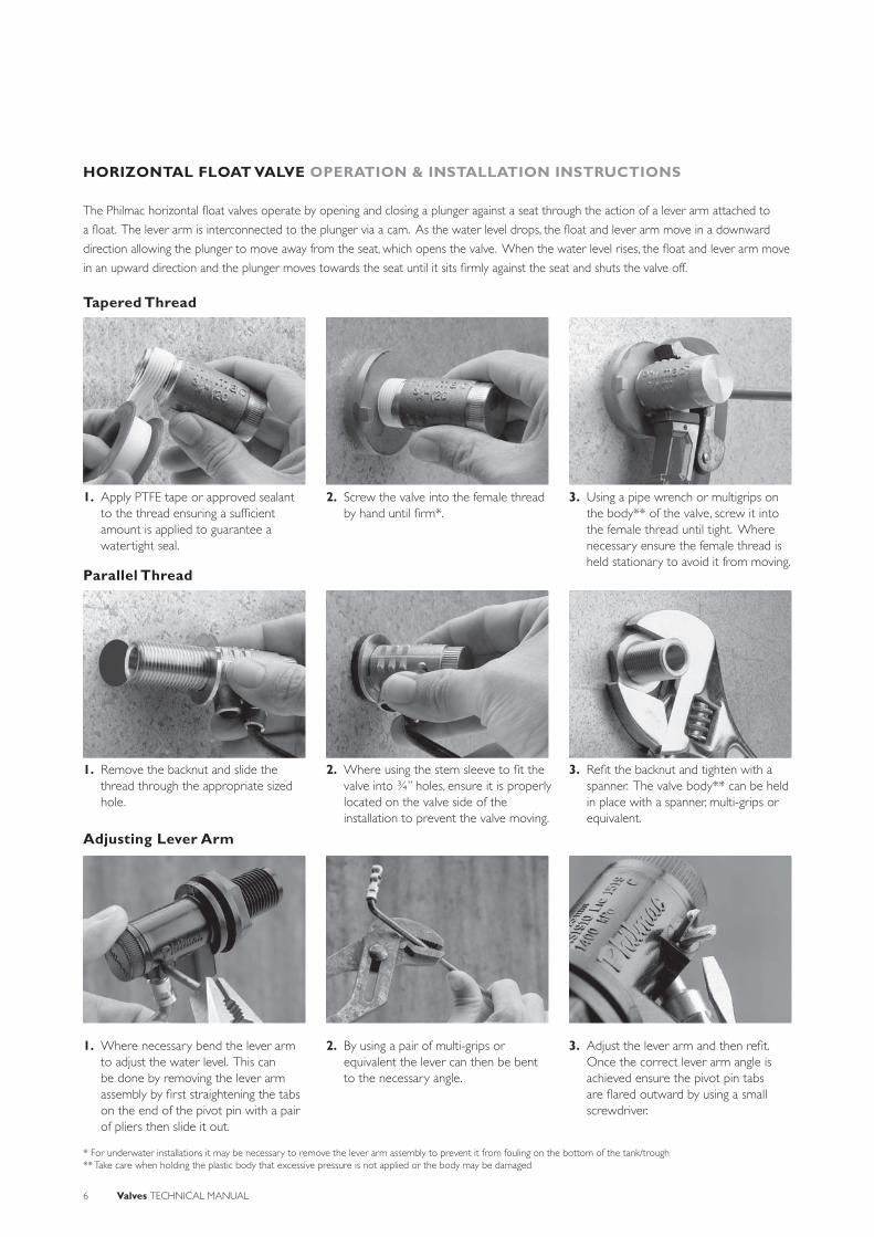
HORIZONTAL FLOAT VALVE OPERATION & INSTALLATION INSTRUCTIONS
1. Apply PTFE tape or approved sealant to the thread ensuring a suffi cient amount is applied to guarantee a watertight seal.
2. Screw the valve into the female thread by hand until fi rm*.
3. Using a pipe wrench or multigrips on the body** of the valve, screw it into the female thread until tight. Where necessary ensure the female thread is held stationary to avoid it from moving.
1. Remove the backnut and slide the thread through the appropriate sized hole.
1. Where necessary bend the lever arm to adjust the water level. This can be done by removing the lever arm assembly by fi rst straightening the tabs on the end of the pivot pin with a pair of pliers then slide it out.
2. Where using the stem sleeve to fi t the valve into ¾” holes, ensure it is properly located on the valve side of the installation to prevent the valve moving.
2. By using a pair of multi-grips or equivalent the lever can then be bent to the necessary angle.
3. Refi t the backnut and tighten with a spanner. The valve body** can be held in place with a spanner, multi-grips or equivalent.
3. Adjust the lever arm and then refi t. Once the correct lever arm angle is achieved ensure the pivot pin tabs are fl ared outward by using a small screwdriver.
The Philmac horizontal fl oat valves operate by opening and closing a plunger against a seat through the action of a lever arm attached to
a fl oat. The lever arm is interconnected to the plunger via a cam. As the water level drops, the fl oat and lever arm move in a downward
direction allowing the plunger to move away from the seat, which opens the valve. When the water level rises, the fl oat and lever arm move
in an upward direction and the plunger moves towards the seat until it sits fi rmly against the seat and shuts the valve off.
* For underwater installations it may be necessary to remove the lever arm assembly to prevent it from fouling on the bottom of the tank/trough** Take care when holding the plastic body that excessive pressure is not applied or the body may be damaged
Parallel Thread
Adjusting Lever Arm
Tapered Thread

Valves TECHNICAL MANUAL 7
Inlet Pressure
(kPa)
Inlet Size
3/8” (DN10)
½” (DN15)
¾” (DN20)
1”(DN25)
1 ¼” (DN32)
1 ½” (DN40)
2”(DN50)
10 1 5 13 23 27 41 65
20 2 7 19 33 40 65 83
30 2 10 23 38 51 81 96
40 3 12 25 48 62 96 162
50 3 13 30 55 71 109 187
100 5 19 41 81 100 153 273
200 8 28 59 114 137 214 385
300 9 34 75 136 164 259 442
400 10 40 87 154 189 296 473
500 11 44 98 167 208 316 484
750 13 49 116 185 238 343 490
1000 16 52 122 191 246 350 496
SYSTEM DESIGN CONSIDERATIONS
Threads: All threads are BSP (Whitworth
form).
Maximum Operating Pressure: 1400 kPa
(200 psi) or 14 bar at 20° C.
Operating temperature: Connection
is cold water (less than 20°C) rated.
However the brass and stainless steel
valves can be used in an environment
where the water is subsequently heated
to 95° C in a tank. In these cases a hot
water rated fl oat must be used.
Floats (balls)Plastic – cold water rated
Plastic – hot water rated (95°C)
Copper – cold water rated
Copper – hot water rated (95°C)
Weathering: All plastic materials used
contain pigments to provide excellent
protection against degradation from
ultra-violet (UV) radiation. However
long-term continuous exposure to
UV is not recommended and plastic
components should ideally be shielded
from direct sunlight. Brass components
are UV resistant.
Air Gap: When connecting to drinking
water the installation should comply with
the relevant air gap standards to prevent
back siphonage.
Flow Rates (L/min)
HO
RIZ
ON
TA
LF
LO
AT
VA
LVE
S

8 Valves TECHNICAL MANUAL
CHEMICAL RESISTANCE
Philmac’s horizontal fl oat valves are primarily designed to convey water. However there may be occasions where the water contains
chemicals and/or alternative fl uids that may need to be controlled. The following table is provided as a guide only for the compatibility
of various chemicals or alternative fl uids to Philmac brass and plastic horizontal fl oat valves. The mixing together of chemicals may affect
the compatibility.
Chemical
Compatibility
BrassFloat Valve
Stainless SteelFloat Valve
PlasticFloat Valve
Acetic acid (10%) N R R
Acetic acid (50%) N R N
Alcohol (ethanol) N R N
Ammonium nitrate N R R
Antifreeze R R R
Brine N R R
Calcium carbonate R R
Calcium chloride R R N
Calcium nitrate R N
Calcium sulphate R N
Chlorine water N R N
Citric Acid N R N
Copper Sulphate >5% N R N
Diesel (fuel) R R R
Ethyl alcohol (ethanol) N R N
Hydrochloric acid (10%) N R N
Hydrochloric acid (30%) N N N
Kerosene R R R
Lubricating oils (not synthetic) R R R
Magnesium nitrate R R
Magnesium sulphate R R R
Mineral oils R R R
Nitric acid (10%) N R N
Nitric acid (40%) N R N
Olive oil R N
Orange juice R R
Petrol R R
Phosphoric acid (85%) N N N
Drinking water R R R
Potassium chloride N R R
Potassium nitrate R R R
Potassium sulphate N R R
Sodium bicarbonate N R R
Sodium hypochlorite (<10%) N R N
Sulphuric acid (10%) R N
Sulphuric acid (30%) R N
Urea R R
Zinc nitrate R
Zinc sulphate R R N
N = Not Recommended R = Resistant Empty Cell = No data availableNote recommendations based on fl uids at 200 C or less

Valves TECHNICAL MANUAL 9
HORIZONTAL FLOAT VALVES MATERIAL & COMPONENTS
Plastic Body with Plastic Seat
Size Nominal Size
Part Number
Body Body Cap Plunger Seal Collar Back Nut Lever Assembly
½” DN15 90300200 Acetal Nylon Acetal Nitrile rubber Integral with body Acetal DZR Brass
½” DN15 90300300 Acetal Nylon Acetal Nitrile rubber Integral with body Acetal DZR Brass
½” DN15 90300400 Acetal Nylon Acetal Nitrile rubber Integral with body Acetal DZR Brass
Note: Outlet Tube is an integral part of the body
Brass Body with 316 Stainless Steel SeatSize Nominal
SizePart
NumberBody Body Cap Plunger Seal Collar* Stem
Sleeve**Back Nut Lever
Assembly
3/8“” DN10 90300500 DZR Brass DZR Brass DZR Brass Nitrile rubber - - - DZR Brass
½” DN15 90300700 DZR Brass DZR Brass DZR Brass Nitrile rubber - - - DZR Brass
½” DN15 90301300 DZR Brass DZR Brass DZR Brass Nitrile rubber DZR Brass - DZR Brass DZR Brass
½” DN15 90301500 DZR Brass DZR Brass DZR Brass Nitrile rubber DZR Brass - DZR Brass DZR Brass
½” DN15 90302300 DZR Brass DZR Brass DZR Brass Nitrile rubber DZR Brass Polypropylene DZR Brass DZR Brass
½” DN15 90303100 DZR Brass DZR Brass DZR Brass Nitrile rubber DZR Brass - DZR Brass DZR Brass
¾” DN20 90304400 DZR Brass DZR Brass DZR Brass Nitrile rubber - - - DZR Brass
1” DN25 90304600 DZR Brass DZR Brass DZR Brass Nitrile rubber - - - DZR Brass
1¼” DN32 90304800 DZR Brass DZR Brass DZR Brass Nitrile rubber - - - DZR Brass
1½” DN40 90404900 DZR Brass DZR Brass DZR Brass Nitrile rubber - - - DZR Brass
2” DN50 90405000 DZR Brass DZR Brass DZR Brass Nitrile rubber - - - DZR Brass
* A collar is only fitted to valves with parallel threads.** A stem sleeve is a stepped washer which allows a ½“ valve to be fitted to a hole that would be used by a ¾“ valve.
Stainless Steel Body with 316 Stainless Steel SeatSize Nominal
SizePart
NumberBody Body Cap Plunger Seal Lever
Assembly
½” DN15 90399100 316 S/S 316 S/S 316 S/S Viton A 316 S/S
¾” DN20 90399200 316 S/S 316 S/S 316 S/S Viton A 316 S/S
1” DN25 90399300 316 S/S 316 S/S 316 S/S Viton A 316 S/S
1½” DN40 90399400 316 S/S 316 S/S 316 S/S Viton A 316 S/S
S.S. SEAT
STEM SLEEVE
BACKNUT
COLLAR
BODY(INCLUDES OUTLET TUBE)
O-RING
SEAT SEAL
PLUNGER
BODY CAP
PIVOT PIN
CAM
HORIZONTAL LEVER(3/8" & 1/2")
ADAPTOR
INLET
BACKNUT
HORIZONTAL LEVER (3/4'' TO 2'')
HO
RIZ
ON
TA
LF
LO
AT
VA
LVE
S
NOTE: ½'' Parallel thread brass body shown.

10 Valves TECHNICAL MANUAL
HORIZONTAL FLOAT VALVES RANGE & DIMENSIONS
The following diagram shows dimensions related to the different horizontal valve sizes. (Dimensions are also shown on page 11).
Brass/Stainless SteelSize(A)
Nominal Size
C E F G H I
3/8“ DN10 36 16.5 17.5 9.5 45 225
½” DN15 46.5 22 23.5 12.7 135 365*
¾” DN20 50.3 28 30 16 96 444
1” DN25 62.2 33 35 19 189 545
1 ¼” DN32 68.5 39 43 22.2 205 580
1 ½” DN40 73.5 44.5 44 25 195 685
2” DN50 88 55 62 32 280 780
* With 200 mm lever All dimensions in millimetres unless otherwise stated
Plastic Float ValvesSize(A)
Nominal Size
C E F G H I
½“ DN15 44 25 24 12 95* 345
* With 200 mm lever
All dimensions in millimetres unless otherwise stated
D
A
E
BG
F
J
H
I
C
L
K
NOTE: Tapered brass body shown.

Valves TECHNICAL MANUAL 11
HORIZONTAL FLOAT VALVES RANGE & DIMENSIONS(Refer page 10 for diagram).
Plastic Body with Plastic SeatSize(A)
Nominal Size
Part Number
Thread Type
B D J K L
½” DN15 90300200 Parallel 41 88 100 250 5/16“ BSW
½” DN15 90300300 Parallel 41 88 100 200 5/16“ BSW
½” DN15 90300400 Parallel 41 88 100 125 5/16“ BSW
All dimensions in millimetres unless otherwise stated
Brass Body with 316 Stainless Steel SeatSize(A)
Nominal Size
Part Number
Thread Type
B D J K L
3/8“ DN10 90300500 Tapered 15 50.9 80/100* 125 5/16“ BSW
½” DN15 90300700 Tapered 15 61.5 100 200 5/16“ BSW
½” DN15 90301300 Parallel 38 84.2 100 250 5/16“ BSW
½” DN15 90301500 Parallel 38 84.2 100 200 5/16“ BSW
½” DN15 90302300 Parallel 38 84.2 100 200 5/16“ BSW
½” DN15 90303100 Parallel 25 71.2 100 200 5/16“ BSW
¾” DN20 90304400 Tapered 19 69.3 150 250 5/16“ BSW
1” DN25 90304600 Tapered 19 80 150 355 5/16“ BSW
1¼” DN32 90304800 Tapered 22 91 175 355 3/8“ BSW
1½” DN40 90404900 Tapered 22 96 200 425 3/8“ BSW
2” DN50 90405000 Tapered 25 114 255 455 ½“ BSW
All dimensions in millimetres unless otherwise stated* For pressures over 1000kPa the 100mm float is recommended.
Stainless Steel Body with 316 Stainless Steal SeatSize(A)
Nominal Size
Part Number
Thread Type
B D J K L
½” DN15 90399100 Tapered 16 61.5 125 255 5/16“ BSW
¾” DN20 90399200 Tapered 18 69.1 125 255 5/16“ BSW
1” DN25 90399300 Tapered 19 80.9 125 355 5/16“ BSW
1 ½” DN40 90399400 Tapered 22 94.3 200 405 3/8“ BSW
All dimensions in millimetres unless otherwise stated
HO
RIZ
ON
TA
LF
LO
AT
VA
LVE
S
12 Valves TECHNICAL MANUAL
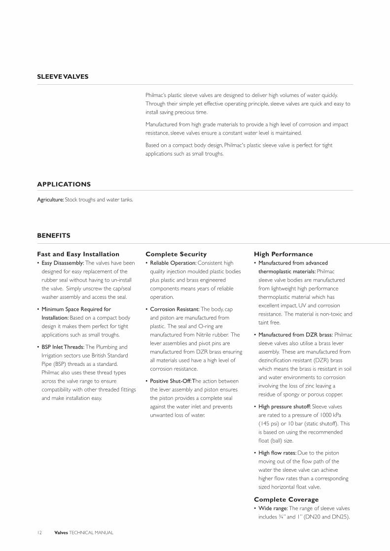
SLEEVE VALVES
Philmac’s plastic sleeve valves are designed to deliver high volumes of water quickly.
Through their simple yet effective operating principle, sleeve valves are quick and easy to
install saving precious time.
Manufactured from high grade materials to provide a high level of corrosion and impact
resistance, sleeve valves ensure a constant water level is maintained.
Based on a compact body design, Philmac's plastic sleeve valve is perfect for tight
applications such as small troughs.
Fast and Easy Installation• Easy Disassembly: The valves have been
designed for easy replacement of the
rubber seal without having to un-install
the valve. Simply unscrew the cap/seal
washer assembly and access the seal.
• Minimum Space Required for Installation: Based on a compact body
design it makes them perfect for tight
applications such as small troughs.
• BSP Inlet Threads: The Plumbing and
Irrigation sectors use British Standard
Pipe (BSP) threads as a standard.
Philmac also uses these thread types
across the valve range to ensure
compatibility with other threaded fi ttings
and make installation easy.
Complete Security• Reliable Operation: Consistent high
quality injection moulded plastic bodies
plus plastic and brass engineered
components means years of reliable
operation.
• Corrosion Resistant: The body, cap
and piston are manufactured from
plastic. The seal and O-ring are
manufactured from Nitrile rubber. The
lever assemblies and pivot pins are
manufactured from DZR brass ensuring
all materials used have a high level of
corrosion resistance.
• Positive Shut-Off: The action between
the lever assembly and piston ensures
the piston provides a complete seal
against the water inlet and prevents
unwanted loss of water.
High Performance• Manufactured from advanced
thermoplastic materials: Philmac
sleeve valve bodies are manufactured
from lightweight high performance
thermoplastic material which has
excellent impact, UV and corrosion
resistance. The material is non-toxic and
taint free.
• Manufactured from DZR brass: Philmac
sleeve valves also utilise a brass lever
assembly. These are manufactured from
dezincifi cation resistant (DZR) brass
which means the brass is resistant in soil
and water environments to corrosion
involving the loss of zinc leaving a
residue of spongy or porous copper.
• High pressure shutoff: Sleeve valves
are rated to a pressure of 1000 kPa
(145 psi) or 10 bar (static shutoff). This
is based on using the recommended
fl oat (ball) size.
• High fl ow rates: Due to the piston
moving out of the fl ow path of the
water the sleeve valve can achieve
higher fl ow rates than a corresponding
sized horizontal fl oat valve.
Complete Coverage• Wide range: The range of sleeve valves
includes ¾” and 1” (DN20 and DN25).
BENEFITS
Agriculture: Stock troughs and water tanks.
APPLICATIONS

Valves TECHNICAL MANUAL 13
Philmac’s range of sleeve valves are
designed to comply with the following
standards and undertake a range of
tests to ensure they comply with these
standards.
StandardsAS1722.1: Pipe threads of Whitworth
form part 1: sealing pipe threads.
ISO7: Pipe threads where pressure tight
joints are made on the threads.
TestsShut Off Test: Valves are tested for shut
off against a hydrostatic water pressure of
2000 kPa (290 psi) or 20 bar.
STANDARDS & TESTS
SL
EE
VE
VA
LVE
S
14 Valves TECHNICAL MANUAL
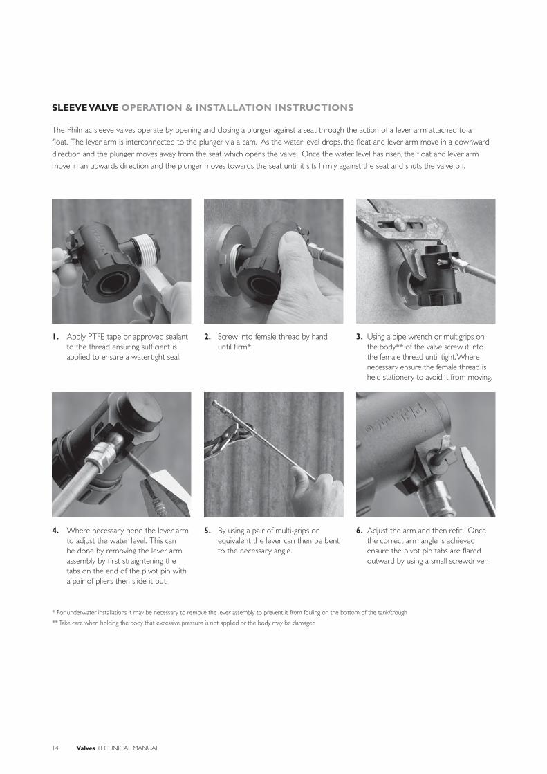
SLEEVE VALVE OPERATION & INSTALLATION INSTRUCTIONS
4. Where necessary bend the lever arm to adjust the water level. This can be done by removing the lever arm assembly by fi rst straightening the tabs on the end of the pivot pin with a pair of pliers then slide it out.
1. Apply PTFE tape or approved sealant to the thread ensuring suffi cient is applied to ensure a watertight seal.
5. By using a pair of multi-grips or equivalent the lever can then be bent to the necessary angle.
2. Screw into female thread by hand until fi rm*.
6. Adjust the arm and then refi t. Once the correct arm angle is achieved ensure the pivot pin tabs are fl ared outward by using a small screwdriver
3. Using a pipe wrench or multigrips on the body** of the valve screw it into the female thread until tight. Where necessary ensure the female thread is held stationery to avoid it from moving.
The Philmac sleeve valves operate by opening and closing a plunger against a seat through the action of a lever arm attached to a
fl oat. The lever arm is interconnected to the plunger via a cam. As the water level drops, the fl oat and lever arm move in a downward
direction and the plunger moves away from the seat which opens the valve. Once the water level has risen, the fl oat and lever arm
move in an upwards direction and the plunger moves towards the seat until it sits fi rmly against the seat and shuts the valve off.
* For underwater installations it may be necessary to remove the lever assembly to prevent it from fouling on the bottom of the tank/trough
** Take care when holding the body that excessive pressure is not applied or the body may be damaged

Valves TECHNICAL MANUAL 15
SYSTEM DESIGN CONSIDERATIONS
Threads: All threads are BSP (Whitworth
form).
Maximum Operating Pressure: 1000 kPa
(145 psi) or 10 bar.
Operating temperature: Connection is
cold water (less than 20°C) rated.
Floats (balls):Plastic – cold water rated
Copper – cold water rated
Weathering: All plastic materials used
contain pigments to provide excellent
protection against degradation from
ultra-violet (UV) radiation. However
long-term continuous exposure to
UV is not recommended and plastic
components should ideally be shielded
from direct sunlight. Brass components
are UV resistant.
InletPressure
(kPa)
Inlet Size
¾” DN20)
1”(DN25)
50 65 65
100 90 90
150 105 105
200 132 132
250 140 140
300 156 156
350 165 165
400 174 174
450 185 185
500 195 195
750 238 238
Chemical Sleeve Valve
Acetic acid (10%) R
Acetic acid (50%) N
Alcohol (ethanol) N
Ammonium nitrate R
Antifreeze R
Brine R
Calcium carbonate R
Calcium chloride N
Calcium nitrate N
Calcium sulphate N
Chlorine water N
Citric Acid N
Copper Sulphate >5% N
Diesel (fuel) R
Ethyl alcohol (ethanol) N
Hydrochloric acid (10%) N
Hydrochloric acid (30%) N
Kerosene R
Lubricating oils (not synthetic) R
Magnesium nitrate R
Magnesium sulphate R
Mineral oils R
Nitric acid (10%) N
Nitric acid (40%) N
Olive oil N
Orange juice R
Petrol R
Phosphoric acid (85%) N
Drinking water R
Potassium chloride R
Potassium nitrate R
Potassium sulphate R
Sodium bicarbonate R
Sodium hypochlorite (<10%) N
Sulphuric acid (10%) N
Sulphuric acid (30%) N
Urea R
Zinc nitrate
Zinc sulphate N
CHEMICAL RESISTANCE
Flow Rates (L/min)
Philmac’s sleeve valves are primarily designed
to convey water. However, there may
be occasions where the water contains
chemicals and/or alternative fl uids need to
be controlled. The following table is provided
as a guide only for the compatibility of
various chemicals and alternative fl uids
to Philmac’s sleeve valves. The mixing of
chemicals may affect the compatibility.
N = Not RecommendedR = ResistantEmpty Cell = No data available
Note recommendations based on
fl uids at 200 C or less
SL
EE
VE
VA
LVE
S

16 Valves TECHNICAL MANUAL
SLEEVE VALVE MATERIAL & COMPONENTS
Size Nominal Size
Part Number
Body Cap Piston Seat Seal O-ring Lever Assembly
¾” DN20 91470200 Acetal Nylon Acetal Nitrile rubber
Nitrile rubber
DZR Brass
1” DN25 91470300 Acetal Nylon Acetal Nitrile rubber
Nitrile rubber
DZR Brass
BODY
PIVOT PIN
LEVER ASSEMBLY
BACKNUT
O-RING
PISTON
SEAT WASHER
INLET
CAP
Valves TECHNICAL MANUAL 17
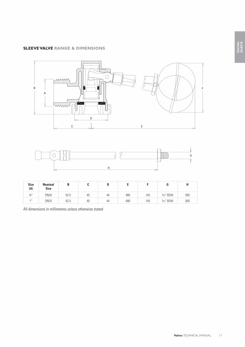
SLEEVE VALVE RANGE & DIMENSIONS
Size(A)
Nominal Size
B C D E F G H
¾” DN20 62.5 45 44 480 145 5/16“ BSW 300
1” DN25 62.5 45 44 480 145 5/16“ BSW 300
All dimensions in millimetres unless otherwise stated
A
B
C E
D
G
H
F
SL
EE
VE
VA
LVE
S
18 Valves TECHNICAL MANUAL
MARK II SERVO TANK FILLING VALVES
Philmac’s Australian made Mark II servo tank fi lling valve is designed to deliver high
volumes of water very quickly.
Due to the unique servo action, the valve requires only a small fl oat, which makes them
ideal for confi ned spaces.
The unique design of the secondary servo action guarantees shut off at extremely high
pressure.
Manufactured from high grade materials the Mark II servo tank is suitable for a range of
applications such as fi re service water tanks.
Fast and Easy Installation• Minimum Space Required for
Installation: Based on a servo action the body has a secondary chamber which assists the lever/fl oat assembly in closing the valve. This reduces the length of lever arm and fl oat size that would otherwise be required to close at high pressures. With a compact body design it makes them perfect for tight applications such as fi re service tanks.
• BSP Inlet/Outlet Threads: The Industrial and Plumbing sectors use British Standard Pipe (BSP) threads as a standard. Philmac also uses these thread types across the valve range to ensure compatibility with other threaded fi ttings making installation easy.
• Hexagonal Inlet/Outlet: Both the inlet and outlet are hexagonal in shape to make it easy to use a spanner or pipe wrench for installation.
• Easy Disassembly: The valves have been designed allowing easy replacement of the seals and O-rings. Simply remove the pivot pin, disconnect the lever arm assembly and remove the hexagonal seat bottom to allow the piston assembly to slide out and access the seals and O-rings.
Complete Security• Servo Sealing Action: By allowing water
into the top chamber of the body it
provides an additional or secondary
force to the piston to assist the lever/
fl oat assembly and provide complete
shutoff.
• Corrosion Resistant: With a gun metal
body, 316 stainless steel seat, DZR
brass components, polypropylene split
ring, nitrile O-rings and seals, the valve
is manufactured using high corrosion
resistant materials.
• Float Security: The lever arm has been
designed so that the copper fl oat slides
over the lever arm and is secured with
a cotter pin to prevent it coming loose.
In addition, by sliding the fl oat onto the
lever arm it ensures force is applied to
the complete fl oat not just a socket on
the end. This ensures reliable operation.
• Approvals: All valves comply with
Australian/New Zealand Standard 4020
which means the valves are suitable for
use with drinking water.
High Performance• Manufactured from DZR brass: The
brass components in Philmac servo
tank fi lling valves are manufactured from
dezincifi cation resistant (DZR) brass.
This means the brass is resistant in soil
and water environments to corrosion
involving the loss of zinc leaving a
residue of spongy or porous copper.
• High pressure shutoff: Servo tank
fi lling valves are rated to a pressure
of 2000 kPa (290psi) or 20 bar (static
shutoff) at 200 Celsius to meet the
requirements of high pressure systems.
Complete Coverage• Wide range: The range of servo tank
fi lling valves is comprehensive and includes
1½", 2" and 3" (DN40, 50 and 80).
BENEFITS
Agriculture: Water tanks on bore schemes.
Plumbing: Water tanks for drinking water and fi re service tanks
APPLICATIONS
Valves TECHNICAL MANUAL 19
Philmac’s range of servo tank fi lling valves
are designed to comply with the following
standards and undertake a range of
tests to ensure they comply with these
standards.
StandardsAS/NZ 4020: Testing of products for use
in contact with drinking water.
AS 1722.1: Pipe threads of Whitworth
form part 1: sealing pipe threads.
ISO7: Pipe threads where pressure tight
joints are made on the threads.
TestsShut Off Test: Valves are tested for shut
off against a hydrostatic water pressure of
2000 kPa (290 psi) or 20 bar.
Strength Test: Valves are tested for
adequate strength for their intended
application. This includes testing at the
maximum recommended operating
temperature and a pressure of 3000 kPa
(435 psi) or 30 bar.
STANDARDS & TESTS
SE
RV
O T
AN
K
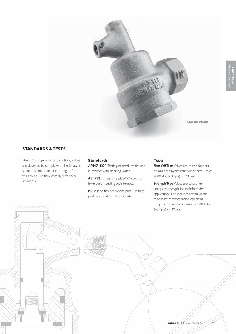
Lever arm included
SE
RV
O T
AN
KF
ILL
ING
VA
LVE
S

20 Valves TECHNICAL MANUAL
MARK II SERVO TANK FILLING VALVES OPERATION & INSTALLATION INSTRUCTIONS
1. Apply PTFE tape or approved sealant to the inlet thread ensuring suffi cient is applied to ensure a watertight seal.
2. Screw into female thread by hand until fi rm.
3. Using a pipe wrench or multigrips on the hex of the valve, screw it into the female thread until tight. Where necessary ensure the female thread is held stationary to avoid it from moving.
4. Thread the lever arm through a 10” (255 mm) copper fl oat (ball) and tighten.
5. Fit the split (cotter) pin on the end of the arm to prevent it from coming loose.
6. Remove the pivot pin from the body and fi t the lever arm then ensure the pivot pin tabs are fl ared outward by using a small screwdriver.
The Philmac servo tank fi lling valves operate by opening and closing a piston against a seat through the action of a lever arm attached to a fl oat. The lever arm is interconnected to the secondary piston via a cam.
As the water level drops, the fl oat and lever arm move in a downward direction and the secondary piston lifts allowing water in the top chamber to pass downstream. The secondary piston in interconnected to the main piston and as it lifts so does the main piston which moves it away from the seat and opens the valve.
When the water level rises, the fl oat and lever arm move in an upwards direction and the secondary and main piston moves towards the seat until it sits fi rmly against the seat. Water then enters the top chamber by passing along the side of the main piston and through a small slot in the piston split ring. By doing this, water pressure is applied to the main piston. This secondary or servo action combined with the action of the fl oat and lever arm ensures the valve shuts off.
HOLES DRILLED IN PIPEFOR AIR GAP
BAFFLE PLATE
PIPE WITH 45º ELBOW
Schematic diagram showing a typical installation
with either a baffl e plate to minimise fl oat
bounce or a pipe to direct water away from
the fl oat and prevent fl oat bounce.

Valves TECHNICAL MANUAL 21
SYSTEM DESIGN CONSIDERATIONS
Threads: All threads are BSP (Whitworth
form).
Maximum Operating Pressure: 3500 kPa
(435 psi) or 35 bar.
Sealing threads: Philmac recommends
sealing threads with PTFE tape. When
being fi tted to a metal thread an
approved metal sealant can be used.
Operating temperature: Connection is
cold water (less than 200C) rated.
Weathering: All non-ferrous materials
are protected from the affects of UV.
Air Gap: When connecting to drinking
water the installation should comply with
the relevant air gap standards to prevent
back siphonage.
Flow Rates (L/min)
Inlet Pressure
(kPa)
Inlet Size
1 ½”(DN40)
2”(DN50)
3”(DN80)
100 420 600 1440
150 510 720 1680
200 600 840 1960
250 670 960 2170
300 730 1020 2290
350 770 1080 2460
400 800 1140 2580
450 830 1220 2700
500 900 1300 2820
Valve selection should be directly related to demand and not to pipe size. The fl ow
required should be determined at a given dynamic pressure and then the valve
should be selected from the table above.
CHEMICAL RESISTANCE
Philmac’s servo tank fi lling valves are
primarily designed to convey water.
However there may be occasions where
the water contains chemicals and/or
alternative fl uids need to be controlled. The
following table is provided as a guide only
for the compatibility of various chemicals
and alternative fl uids to Philmac servo
tank fi lling valves. The mixing together of
chemicals may affect the compatibility.
Chemical CompatibilityAcetic acid (10%) NAcetic acid (50%) NAlcohol (ethanol) NAmmonium nitrate NAntifreeze RBrine RCalcium carbonateCalcium chloride NCalcium nitrateCalcium sulphateChlorine water NCitric Acid NCopper Sulphate >5% NDiesel (fuel) REthyl alcohol (ethanol) NHydrochloric acid (10%) NHydrochloric acid (30%) NKerosene RLubricating oils (not synthetic) RMagnesium nitrateMagnesium sulphate RMineral oils RNitric acid (10%) NNitric acid (40%) NOlive oilOrange juicePetrolPhosphoric acid (85%) NDrinking water RPotassium chloride NPotassium nitrate RPotassium sulphate NSodium bicarbonate NSodium hypochlorite (<10%) NSulphuric acid (10%)Sulphuric acid (30%)UreaZinc nitrateZinc sulphate R
N = Not RecommendedR = ResistantEmpty Cell = No data available
Note recommendations based on
fl uids at 200 C or less
SE
RV
O T
AN
KF
ILL
ING
VA
LVE
S

22 Valves TECHNICAL MANUAL
MARK II SERVO TANK FILLING VALVES MATERIAL & COMPONENTS
Servo Tank Filling ValveSize Nominal
SizePart
NumberBody Body Cap Pivot Pin Cam Lever Cotter Pin Seat
Bottom
1½” DN40 90381500 Gun Metal DZR brass DZR brass DZR brass DZR brass DZR brass DZR brass + 316 S/S
2” DN50 90381600 Gun Metal DZR brass DZR brass DZR brass DZR brass DZR brass DZR brass + 316 S/S
3” DN80 90381700 Gun Metal DZR brass DZR brass DZR brass DZR brass DZR brass DZR brass + 316 S/S
Size Nominal Size
Part Number
Piston - Main
Piston Seat Retainer
Screw Retainer
Seat Seal O-ring Split Ring
1½” DN40 90381500 DZR brass DZR brass DZR brass DZR brass Nitrile rubber
Nitrile rubber
Polyethylene
2” DN50 90381600 DZR brass DZR brass DZR brass DZR brass Nitrile rubber
Nitrile rubber
Polyethylene
3” DN80 90381700 DZR brass DZR brass DZR brass DZR brass Nitrile rubber
Nitrile rubber
Polyethylene
PIVOT PIN
CAM
LEVER
COTTER PIN
PISTON
O-RING
SEAT
BODY
BODY CAP
SPLIT RING
SEAT RETAINER
SEAT WASHER
PISTON - MAIN
SCREW RETAINER
SEAT WASHER
SEAT RETAINER
O-RING
SEAT BOTTOM
INLET

Valves TECHNICAL MANUAL 23
MARK II SERVO TANK FILLING VALVES RANGE & DIMENSIONS
Size(A)
Nominal Size
B C D E F G H I J K
1 ½” DN40 110 165 70 1½” 760 255 260 ½“ BSW 750 135
2” DN50 110 170 80 2” 890 255 260 ½“ BSW 860 135
3” DN80 145 225 110 3” 1040 255 410 ½“ BSW 1000 135
All dimensions in millimetres unless otherwise stated
A
B
C
D
E
F
I
J
K
G
H
SE
RV
O T
AN
KF
ILL
ING
VA
LVE
S

24 Valves TECHNICAL MANUAL
CISTERN VALVES
Philmac’s plastic cistern valve is a compact unit offering easy installation and operation
guaranteeing constant water level is maintained.
The simple design and features of the cistern valve ensures the fi lling of the tank is slow
and controlled avoiding water hammer. The valve also includes a built-in reservoir tube
(baffl e) ensuring a silent operation.
Philmac’s robust cistern valves are manufactured from high grade quality materials
providing corrosion and impact resistance.
Fast and Easy Installation• Easy Disassembly: The valve has
been designed for easy replacement
of the rubber seal without having to
un-install the valve. Simply remove the
pivot pin and the lever assembly then
unscrew the pillar cap and remove the
plunger/seal.
• Minimum Space Required for Installation: Based on a compact
body design the valve is perfect for tight
applications such as a small cistern.
• BSP Inlet Threads: The Plumbing and
Irrigation sectors use British Standard
Pipe (BSP) threads as a standard.
Philmac also uses these thread types
across the valve range to ensure
compatibility with other threaded fi ttings
and make installation easy.
Complete Security• Reliable Operation: Consistent
high quality injection moulded plastic
bodies plus plastic and brass engineered
components means years of reliable
operation.
• Corrosion Resistant: The body,
cap and piston are manufactured
from plastic. The seal and O-ring are
manufactured from Nitrile rubber. The
lever assemblies and pivot pins are
manufactured from DZR brass ensuring
all components used have a high degree
of corrosion resistance.
• Positive Shut-Off: The action
between the lever assembly and piston
ensures the piston provides a complete
seal against the water inlet and prevents
unwanted loss of water.
• Approvals: All valves comply with
Australian Standard ATS 5200.016 which
means that the valves meet performance
requirements for backfl ow prevention,
back siphonage and endurance testing,
as well as material construction
requirements.
High Performance• Manufactured from advanced
thermoplastic materials: Philmac's
cistern valve bodies are manufactured
from lightweight high performance
thermoplastic material which has
excellent impact, UV and corrosion
resistance. The material is non-toxic and
taint free.
• Manufactured from DZR brass: Philmac cistern valves also utilise a brass
lever assembly. These are manufactured
from dezincifi cation resistant (DZR)
brass which means the brass is resistant
in soil and water environments to
corrosion involving the loss of zinc
leaving a residue of spongy or porous
copper.
• High pressure shutoff: Cistern valves
are rated to a pressure of 1400 kPa
(200 psi) or 14 bar (static shutoff). This
is based on using the recommended
fl oat (ball) size.
• Quiet operation: A built-in reservoir
tube (noise baffl e) minimises noise for a
quiet operation.
BENEFITS
Industrial: Commercial airconditioning units and toilet cisterns.
APPLICATIONS

Valves TECHNICAL MANUAL 25
Philmac’s range of sleeve valves are
designed to comply with the following
standards and undertake a range of
tests to ensure they comply with these
standards.
StandardsATS 5200.016: Technical specifi cations for
plumbing and drainage products – cistern
inlet valves.
AS1722.1: Pipe threads of Whitworth
form part 1: sealing pipe threads.
ISO7: Pipe threads where pressure tight
joints are made on the threads.
Tests Shut Off Test: Valves are tested for shut
off against a hydrostatic water pressure of
2000 kPa (290 psi) or 20 bar.
Endurance Test: Operating mechanisms
are subjected to 50,000 cycles. This
simulates opening and closing operations
during the design service life of the valve.
Backfl ow Prevention / Back Siphonage: The valve is tested to show that no cistern
water can return into the main supply.
STANDARDS & TESTS
CIS
TE
RN
VA
LVE
S

26 Valves TECHNICAL MANUAL
CISTERN VALVES OPERATION & INSTALLATION INSTRUCTIONS
1. Insert the cam end of the lever assembly into the valve plunger recess. This may require rotation of the plunger to align it to the correct position. Align the cam hole with the valve housing and insert the pivot pin then fl are the ends to secure.
2. Remove the back nut from the bottom of the valve and insert the threaded section of the valve into the base of the cistern or small tank. Ensure the stem sleeve is in direct contact with the base of the tank so that it seals and prevents water from leaking.
3. Screw the back nut onto the thread and tighten.
4. Where necessary bend the lever arm to adjust the water level. This can be done by removing the lever arm assembly by fi rst straightening the tabs on the end of the pivot pin with a pair of pliers then slide it out.
By using a pair of multi-grips or equivalent the lever can then be bent to the necessary angle.
Adjust the lever arm and then refi t. Once the correct lever arm angle is achieved ensure the pivot pin tabs are fl ared outward by using a small screwdriver.
The Philmac cistern valves operate by opening and closing a plunger against a seat through the action of a lever arm attached to a fl oat. The
lever arm is interconnected to the plunger via a cam. As the water level drops, the fl oat and lever arm move in a downward direction allowing
the plunger to move away from the seat, which opens the valve. When the water level rises, the fl oat and lever arm move in an upward
direction and the plunger moves towards the seat until it sits fi rmly against the seat and shuts the valve off.

Valves TECHNICAL MANUAL 27
SYSTEM DESIGN CONSIDERATIONS
Threads: All threads are BSP (Whitworth
form).
Maximum Operating Pressure: 1400 kPa
(200 psi) or 14 bar.
Operating temperature: Connection is
cold water (less than 200C) rated.
Float (ball): Plastic – cold water rated
Weathering: All plastic materials used
contain pigments to provide excellent
protection against degradation from
ultra-violet (UV) radiation. However
long-term continuous exposure to
UV is not recommended and plastic
components should ideally be protected.
Brass components are UV resistant.
Air Gap: When connecting to drinking
water the installation should comply with
the relevant air gap standards to prevent
back siphonage.
Flow Rates (L/min)
Inlet Pressure
(kPa)Flow Rate
25 2.2
50 3.1
75 3.9
100 4.5
150 5.6
200 6.4
250 7.1
300 7.8
400 9.2
500 10.4
CHEMICAL RESISTANCE
Philmac’s cistern valve has been designed
to convey water. However there may
be occasions where the water contains
chemicals and/or alternative fl uids
need to be controlled. The following
table is provided as a guide only for
the compatibility of various chemicals
to Philmac’s cistern valve. The mixing
together of chemicals may affect the
compatibility.
Chemical CisternAcetic acid (10%) RAcetic acid (50%) NAlcohol (ethanol) NAmmonium nitrate RAntifreeze RBrine RCalcium carbonate RCalcium chloride RCalcium nitrate RCalcium sulphateChlorine water NCitric Acid RCopper Sulphate >5% NDiesel (fuel) REthyl alcohol (ethanol) NHydrochloric acid (10%) NHydrochloric acid (30%) NKerosene NLubricating oils (not synthetic) RMagnesium nitrate RMagnesium sulphate RMineral oils RNitric acid (10%) NNitric acid (40%) NOlive oil ROrange juice RPetrol RPhosphoric acid (85%) NDrinking water RPotassium chloride RPotassium nitrate RPotassium sulphateSodium bicarbonateSodium hypochlorite (<10%) NSulphuric acid (10%) NSulphuric acid (30%) NUrea RZinc nitrate NZinc sulphate
N = Not RecommendedR = ResistantEmpty Cell = No data available
Note recommendations based on
fl uids at 200 C or less
CIS
TE
RN
VA
LVE
S

28 Valves TECHNICAL MANUAL
CISTERN VALVES MATERIAL & COMPONENTS
Size Nominal Size Part Number Pillar Tube Pillar Tube Cap Reservoir Tube Velocity Rod
½” DN20 91152700 GF Nylon GF Nylon Polypropylene GF Nylon
Backnut Seat Seal Plunger Pivot Pin O-ring Lever Assembly Stem Sleeve
GF Acetal Nitrile rubber GF Acetal DZR brass EPDM rubber DZR brass Rubber
PLUNGERSEAT SEAL
PIVOT PINO-RING
PILLAR TUBE CAP
RESEVOIR TUBE
LEVER
STEM SLEEVEBACKNUTVELOCITY RODPILLAR TUBE
INLET

Valves TECHNICAL MANUAL 29
CISTERN VALVES RANGE & DIMENSIONS
Size(A)
Nominal Size
B C D E F G H
½” DN15 48.5 336 395 100 130 5/16“ BSW 272
All dimensions in millimetres unless otherwise stated
B
C
E
F
D
A
H
G
CIS
TE
RN
VA
LVE
S
30 Valves TECHNICAL MANUAL
BLUE HANDLED BALL VALVES
The Philmac blue handled ball valve has been servicing the Rural, Irrigation and Plumbing
industries for over 20 years. With the Watermark approval and suitable for drinking
water, this is an extremely versatile valve.
Their distinctive blue easy grip handle is recognised in the market as the industry
standard providing users with the confi dence of a strong, reliable and robust product.
This Australian made blue handled ball valve is based on a simple on/off action and is
quick and easy to install allowing the user full control of water distribution.
With the increasing importance of water management Philmac has expanded their range
to include a purple handle recycled water ball valve.
Fast and Easy Installation• Multi-directional Flow: The blue
handled valves have been designed to
work in either direction to ensure easy
installation and eliminate the need to
look for identifi cation marks.
• BSP Inlet Threads: The Rural, Irrigation
and Plumbing sectors use British
Standard Pipe (BSP) threads as a
standard. Philmac also uses these thread
types across the valve range to ensure
compatibility with other threaded fi ttings
and make installation easy.
• Easy Grip T-handle: The blue handle has
been ergonomically designed to allow it
to be gripped easily and avoid slippage.
• Multi-position Installation: The blue
handled valves can be installed in any
orientation to assist with all types of
installations.
Complete Security• Reliable Operation: Consistent high
quality injection moulded plastic bodies and components plus Nitrile O-rings and a stainless steel screw means years of reliable operation.
• Corrosion Resistant: with a plastic body and components, nitrile O-rings and a 316 stainless steel handle screw, the components used all have a high degree of corrosion resistance.
• Positive Open-Close: The blue handle only rotates through 90° between fully open and fully closed before resting against a stop to ensure there is no guesswork required as to whether it is open or closed.
• Visual Indicator: When in the closed position the blue handle sits at 90° to the body and when in the open position sits in-line with the body clearly indicating whether the valve is open or closed.
• Approvals: All blue handled valves comply with Australian/New Zealand Standard 4020 which means the valves are suitable for use with potable (drinking) water.
High Performance• Manufactured from advanced
thermoplastic materials: Philmac blue
handled ball valves are manufactured
from lightweight high performance
thermoplastic materials which have
excellent impact, UV and corrosion
resistance. The material is non-toxic and
taint free.
• High pressure shutoff: Blue handled
ball valves are rated to a pressure of
1400 kPa (200 psi) or 14 bar (static
shutoff) at 20° Celsius to meet the
requirements of high pressure systems.
Complete Coverage• Wide range: The range of blue handed
ball valves is comprehensive and includes
sizes from ½” to 2” (DN10 to DN50).
In addition the whole range is available
with optional purple handles for use
with recycled water.
BENEFITS
APPLICATIONS
Agriculture: Stock troughs and water tanks.
Irrigation: Master valves, fi eld valves, isolating valves, water tanks
Plumbing: Isolating valves
Municipal: Main stop and curb stop valves
Valves TECHNICAL MANUAL 31
Philmac’s range of blue handed ball valves
are designed to comply with the following
standards and undertake a range of
tests to ensure they comply with these
standards.
StandardsAS/NZ 4020: Testing of products for use
in contact with drinking water.
AS 1722.1: Pipe threads of Whitworth
form part 1: sealing pipe threads.
ISO7: Pipe threads where pressure tight
joints are made on the threads.
TestsShut Off Test: Blue handled ball valves are
tested for shut off against a hydrostatic
water pressure of 2000 kPa (290 psi) or
20 bar.
Strength Test: Blue handled ball valves
are tested for adequate strength for their
intended application.
STANDARDS & TESTS
BL
UE
HA
ND
LE
D
BA
LL
VA
LVE
S
32 Valves TECHNICAL MANUAL
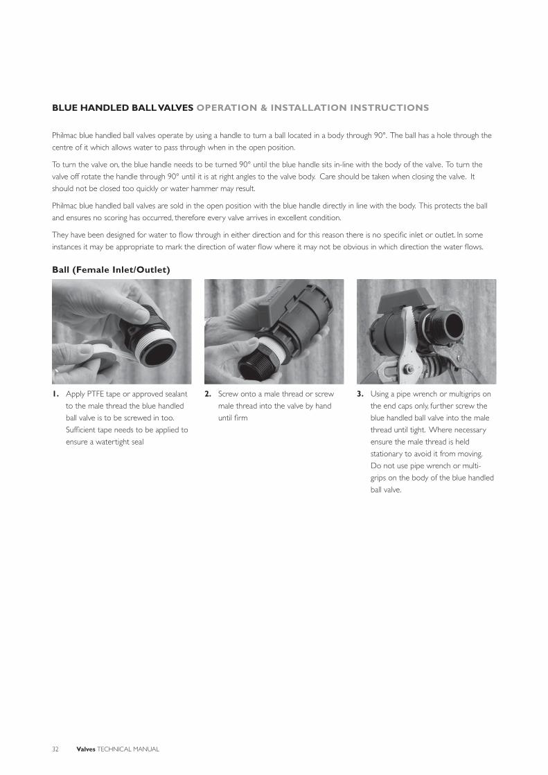
BLUE HANDLED BALL VALVES OPERATION & INSTALLATION INSTRUCTIONS
1. Apply PTFE tape or approved sealant
to the male thread the blue handled
ball valve is to be screwed in too.
Suffi cient tape needs to be applied to
ensure a watertight seal
2. Screw onto a male thread or screw
male thread into the valve by hand
until fi rm
3. Using a pipe wrench or multigrips on
the end caps only, further screw the
blue handled ball valve into the male
thread until tight. Where necessary
ensure the male thread is held
stationary to avoid it from moving.
Do not use pipe wrench or multi-
grips on the body of the blue handled
ball valve.
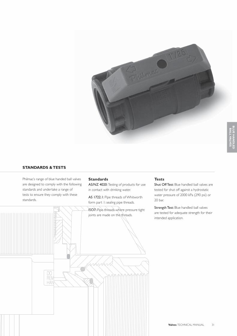
Philmac blue handled ball valves operate by using a handle to turn a ball located in a body through 90°. The ball has a hole through the
centre of it which allows water to pass through when in the open position.
To turn the valve on, the blue handle needs to be turned 90° until the blue handle sits in-line with the body of the valve. To turn the
valve off rotate the handle through 90° until it is at right angles to the valve body. Care should be taken when closing the valve. It
should not be closed too quickly or water hammer may result.
Philmac blue handled ball valves are sold in the open position with the blue handle directly in line with the body. This protects the ball
and ensures no scoring has occurred, therefore every valve arrives in excellent condition.
They have been designed for water to fl ow through in either direction and for this reason there is no specifi c inlet or outlet. In some
instances it may be appropriate to mark the direction of water fl ow where it may not be obvious in which direction the water fl ows.
Ball (Female Inlet/Outlet)

Valves TECHNICAL MANUAL 33
SYSTEM DESIGN CONSIDERATIONS
Threads: All threads are BSP (Whitworth
form).
Maximum Operating Pressure: 1400 kPa
(200 psi) or 14 bar.
Sealing threads: Philmac recommends
sealing threads with PTFE tape. Other
approved sealants for plastic materials
can be used providing the sealant does
not enter the valve where it may cause
damage.
Operating temperature: Connection is
cold water (less than 200C) rated.
Weathering: All plastic materials used
contain pigments to provide excellent
protection against degradation from
ultra-violet (UV) radiation. However
long-term continuous exposure to
UV is not recommended and plastic
components should ideally be protected.
Pressure Loss (kPa)
Flow Rate (L/s)
Inlet Size½”
(DN15)¾”
(DN20)1”
(DN25)1 ¼”
(DN32)1 ½”
(DN40)2”
(DN50)
1 14 14 10 * * *
1.5 27 27 11 * * *
2 44 44 13 6 * *
2.5 64 64 16 8 * *
3 89 89 20 11 5 *
4 - - 33 19 8 *
5 - - 50 28 13 *
6 - - 72 39 18 6
7 - - 99 51 23 8
8 - - - 65 30 10
9 - - - 81 37 12
10 - - - 98 45 15
12 - - - - 63 20
14 - - - - 83 26
16 - - - - - 33
18 - - - - - 40
20 - - - - - 49
22 - - - - - 58
24 - - - - - 67
26 - - - - - 78
28 - - - - - 89
* Denotes pressure loss too small to accurately measure but can be assumed to be 5 kPa or less.
CHEMICAL RESISTANCE
Philmac’s blue handled ball valves are
primarily designed to convey water. However
there may be occasions where the water
contains chemicals and/or alternative fl uids
need to be controlled. The following table is
provided as a guide only for the compatibility
of various chemicals and alternative fl uids
to Philmac blue handled ball valves. The
mixing together of chemicals may affect the
compatibility. Philmac blue handled ball valves are NOT suited for acids.
Chemical CompatibilityAcetic acid (10%) RAcetic acid (50%) NAlcohol (ethanol) NAmmonium nitrate RAntifreeze RBrine RCalcium carbonate RCalcium chloride RCalcium nitrate RCalcium sulphateChlorine water NCitric Acid RCopper Sulphate >5% NDiesel (fuel) NEthyl alcohol (ethanol) NHydrochloric acid (10%) NHydrochloric acid (30%) NKerosene RLubricating oils (not synthetic) RMagnesium nitrate RMagnesium sulphate RMineral oils RNitric acid (10%) NNitric acid (40%) NOlive oil ROrange juicePetrol RPhosphoric acid (85%) NDrinking water RPotassium chloride RPotassium nitrate RPotassium sulphateSodium bicarbonateSodium hypochlorite (<10%) NSulphuric acid (10%) NSulphuric acid (30%) NUrea RZinc nitrate NZinc sulphate
N = Not RecommendedR = ResistantEmpty Cell = No data available
Note recommendations based on fl uids at 200 C or less.
BL
UE
HA
ND
LE
D
BA
LL
VA
LVE
S

34 Valves TECHNICAL MANUAL
BLUE HANDLED BALL VALVES MATERIAL & COMPONENTS
Blue Handled Ball ValveSize Nominal
SizePart
NumberBody End Cap Seal Ring Ball Spindle Screw Handle O-rings
½” DN15 95500100 GF Nylon GF Nylon Alloy
Polypropylene+ PTFE
Polypropylene+ PTFE
Nylon or Acetal
316 S/S GF Nylon Nitrile rubber
¾” DN20 95500200 GF Nylon GF Nylon Alloy
Polypropylene+ PTFE
Polypropylene+ PTFE
Nylon or Acetal
316 S/S GF Nylon Nitrile rubber
1” DN25 95500300 GF Nylon GF Nylon Alloy
Polypropylene+ PTFE
Polypropylene+ PTFE
Nylon or Acetal
316 S/S GF Nylon Nitrile rubber
1 ¼” DN32 95500400 GF Nylon GF Nylon Alloy
Polypropylene+ PTFE
Polypropylene+ PTFE
Nylon or Acetal
316 S/S GF Nylon Nitrile rubber
1 ½” DN40 95500500 GF Nylon GF Nylon Alloy
Polypropylene+ PTFE
Polypropylene+ PTFE
Nylon or Acetal
316 S/S GF Nylon Nitrile rubber
2” DN50 95500600 GF Nylon GF Nylon Alloy
Polypropylene+ PTFE
Polypropylene+ PTFE
Nylon or Acetal
316 S/S GF Nylon Nitrile rubber
PLUG
O-RING
O-RING
SEAL RING
END CAP
SCREW
HANDLE
SPINDLE
END CAP
O-RING
BALL
BODY

Valves TECHNICAL MANUAL 35
BLUE HANDLED BALL VALVES RANGE & DIMENSIONS
D
C
B A
Size(A)
NominalSize
PartNumber
B C D
½” DN15 95500100 16.1 72 79
¾” DN20 95500200 16.1 72 86
1” DN25 95500300 20 82 98
1 ¼” DN32 95500400 26 91 110
1 ½” DN40 95500500 32 101 120
2” DN50 95500600 40 119 136
All dimensions in millimetres unless otherwise stated
BL
UE
HA
ND
LE
D
BA
LL
VA
LVE
S

36 Valves TECHNICAL MANUAL
FOOT AND NON-RETURN VALVES
The Australian made Philmac foot and non-return valves are manufactured from the
highest quality materials to ensure years of reliable service.
Based on the simple movement of a piston, both valves are designed to allow water to
fl ow in one direction only to avoid loss of water, prevent backfl ow and ensure pipelines
do not drain. The non-return valve is designed to keep pumps primed. The foot valve is
designed with a fi lter to prevent debris into the pipeline and pump.
Backed by a full range of spare parts, Philmac’s commitment to customer service and
over 20 years in the fi eld this indestructible valve is one that you can rely on and trust.
Fast and Easy Installation• Multi-position Installation: The valves
have been designed to work in either
a vertical (with water moving in an
upwards direction) or horizontal
position for fl exible installation.
• BSP Inlet Threads: The Rural and
Irrigation sectors use British Standard
Pipe (BSP) threads as a standard.
Philmac also uses these thread types
across the valve range to ensure
compatibility with other threaded fi ttings
and make installation easy.
• Flow Identifi cation: The body is clearly
marked with an arrow to indicate the
direction of fl ow of water.
Complete Security• Reliable Operation: Consistent high
quality injection moulded plastic bodies
and components plus Nitrile O-rings
and a stainless steel spring means years
of reliable operation.
• Corrosion Resistant: with a plastic body
and components, nitrile O-rings and a
316 stainless steel spring, all components
are made from high quality corrosion
resistant materials.
• Protective Screen: A screen is fi tted as
standard to the foot valve to minimise
the entry of large objects which may
cause the piston to jam and leave the
valve in an open position.
High Performance• Manufactured from advanced
thermoplastic materials: Philmac foot
and non-return valves are manufactured
from lightweight high performance
thermoplastic materials, which have
excellent impact, UV and corrosion
resistance. The material is non-toxic and
taint free.
• High pressure rating: Foot and non-
return valves are rated to a pressure
of 1400 kPa (200 psi) (static shutoff) at
200 Celsius to meet the requirements of
high pressure systems.
• Low pressure shutoff: Foot and non-
return valves are designed to seal off at
20 kPa of pressure making them well
suited to gravity feed systems.
Complete Coverage• Wide range: The range of foot and
non-return valves is comprehensive and
includes sizes from ½” to 2” (DN10 to
DN50).
BENEFITS
Agriculture: Foot valves on pumps. Non-return on elevated pipelines.
Irrigation: Foot valves on pumps. Non-return on rising mainlines.
APPLICATIONS

Valves TECHNICAL MANUAL 37
Philmac’s range of foot and non-return
valves are designed to comply with the
following standards and undertake a range
of tests to ensure they comply with these
standards.
StandardsAS 1722.1: Pipe threads of Whitworth
form part 1: sealing pipe threads.
ISO7: Pipe threads where pressure tight
joints are made on the threads
TestsShut Off Test: Valves are tested for shut
off against a hydrostatic water pressure of
16 kPa (2.3 psi) or 0.16 bar and 200 kPa
(29 psi) or 2 bar.
STANDARDS & TESTS
FO
OT
AN
D N
ON
-R
ET
UR
N V
ALV
ES
Non-Return Valve Foot Valve

38 Valves TECHNICAL MANUAL
FOOT AND NON-RETURN VALVES OPERATION & INSTALLATION INSTRUCTIONS
1. Apply PTFE tape or approved sealant
to the male thread the non-return/
foot valve is to be screwed into.
Suffi cient tape needs to be applied to
ensure a watertight seal.
2. Screw the valve onto male thread by
hand until fi rm. Confi rm the correct
orientation of the valve by checking
the water direction arrow is pointing
downstream.
3. Using a pipe wrench or multigrips on the end caps only, further screw the non-return/foot valve into the male thread until tight. Where necessary ensure the male thread is held stationary to avoid it from moving. Do not use pipe wrench or multi-grips on the body of the non-return/foot valve.
Philmac’s foot and non-return valves have been designed to allow water to fl ow in one direction only. The direction of water fl ow is
clearly marked by an arrow on the body of the valve. Under no fl ow conditions the spring assisted piston sits in the closed position.
Philmac foot and non-return valves can be connected to both plastic and metal threaded fi ttings. PTFE tape or an approved sealant is
required.

Valves TECHNICAL MANUAL 39
SYSTEM DESIGN CONSIDERATIONS
Minimum Sealing Pressure: 20 kPa (3 psi)
or 2 m or 0.2 bar of head at 200C.
Maximum Operating Pressure: 1400 kPa
(200 psi) at 200C.
Threads: All threads are BSP (Whitworth
form).
Sealing threads: Philmac recommends
sealing threads with PTFE tape. Other
approved sealants for plastic materials can
be used providing the sealant does not
enter the valve where it may cause damage.
Operating temperature: Connection is
cold water (less than 200C) rated.
Weathering: All plastic materials used
contain pigments to provide excellent
protection against degradation from
ultra-violet (UV) radiation. However
long-term continuous exposure to
UV is not recommended and plastic
components should ideally be protected.
Pressure Loss (kPa) – Foot ValvesFlow Rate (L/s)
Inlet Size¾”
(DN20)1”
(DN25)1 ¼”
(DN32)1 ½”
(DN40)2”
(DN50)0.5 22 20 * * *1 36 23 13 * *
1.5 58 32 14 * *2 88 48 16 13 *
2.5 124 70 20 14 *3 - 99 25 15 104 - - 39 21 105 - - 59 32 126 - - 85 47 127 - - 116 68 138 - - - 92 179 - - - 122 22
10 - - - - 3011 - - - - 3912 - - - - 4913 - - - - 6214 - - - - 7615 - - - - 9216 - - - - 110
* Denotes pressure loss too small to accurately measure
Pressure Loss (kPa) – Non-Return ValvesFlow Rate (L/s)
Inlet Size¾”
(DN20)1”
(DN25)1 ¼”
(DN32)1 ½”
(DN40)2”
(DN50)0.5 15 18 * * *1 27 20 15 * *
1.5 49 24 17 * *2 80 30 18 13 *
2.5 121 38 19 13 *3 - 48 22 13 104 - 74 32 15 105 - 108 46 21 106 - - 66 30 107 - - 91 42 118 - - 121 57 149 - - - 75 18
10 - - - 97 2411 - - - - 3012 - - - - 3813 - - - - 4714 - - - - 5715 - - - - 6916 - - - - 8117 - - - - 95
* Denotes pressure loss too small to accurately measure
CHEMICAL RESISTANCE
Philmac’s foot and non-return valves are
primarily designed to convey water. However
there may be occasions where the water
contains chemicals and/or alternative fl uids
need to be controlled. The following
table is provided as a guide only for
the compatibility of various chemicals to
Philmac foot and non-return valves. The
mixing together of chemicals may affect the
compatibility. Philmac foot and non-return valves are NOT suited for acids.
Chemical CompatibilityAcetic acid (10%) RAcetic acid (50%) NAlcohol (ethanol) NAmmonium nitrate RAntifreeze RBrine RCalcium carbonate RCalcium chloride RCalcium nitrate RCalcium sulphateChlorine water NCitric Acid RCopper Sulphate >5% NDiesel (fuel) REthyl alcohol (ethanol) NHydrochloric acid (10%) NHydrochloric acid (30%) NKerosene RLubricating oils (not synthetic) RMagnesium nitrate RMagnesium sulphate RMineral oils RNitric acid (10%) NNitric acid (40%) NOlive oil ROrange juice RPetrol RPhosphoric acid (85%) NDrinking water RPotassium chloride RPotassium nitrate RPotassium sulphateSodium bicarbonateSodium hypochlorite (<10%) NSulphuric acid (10%) NSulphuric acid (30%) NUrea RZinc nitrate NZinc sulphate
N = Not RecommendedR = ResistantEmpty Cell = No data availableNote recommendations based on fl uids at 200 C or less
FO
OT
AN
D N
ON
-R
ET
UR
N V
ALV
ES

40 Valves TECHNICAL MANUAL
FOOT AND NON-RETURN VALVES MATERIAL & COMPONENTS
Foot ValvesSize Nominal Size Part Number Body Inlet/Outlet Piston Seal Ring O-rings Spring Filter
¾” DN20 95501200 GF Nylon GF Nylon Alloy Acetal Nitrile rubber Nitrile rubber 316 S/S Acetal
1” DN25 95501300 GF Nylon GF Nylon Alloy Acetal Nitrile rubber Nitrile rubber 316 S/S Acetal
1 ¼” DN32 95501400 GF Nylon GF Nylon Alloy Acetal Nitrile rubber Nitrile rubber 316 S/S Acetal
1 ½” DN40 95501500 GF Nylon GF Nylon Alloy Acetal Nitrile rubber Nitrile rubber 316 S/S Acetal
2” DN50 95501600 GF Nylon GF Nylon Alloy Acetal Nitrile rubber Nitrile rubber 316 S/S Acetal
Non-Return ValvesSize Nominal Size Part Number Body Inlet/Outlet Piston Seal Ring O-rings Spring
¾” DN20 95501200 GF Nylon GF Nylon Alloy Acetal Nitrile rubber Nitrile rubber 316 S/S
1” DN25 95501300 GF Nylon GF Nylon Alloy Acetal Nitrile rubber Nitrile rubber 316 S/S
1 ¼” DN32 95501400 GF Nylon GF Nylon Alloy Acetal Nitrile rubber Nitrile rubber 316 S/S
1 ½” DN40 95501500 GF Nylon GF Nylon Alloy Acetal Nitrile rubber Nitrile rubber 316 S/S
2” DN50 95501600 GF Nylon GF Nylon Alloy Acetal Nitrile rubber Nitrile rubber 316 S/S
SEALO-RING
PISTON
INLET CAP
FILTER
SPRIN
BOD
OUT
INLET
SEAL RINGO-RING
PISTON
INLET CAP
SPRING
BODY
OUTLET CAP
INLET
Valves TECHNICAL MANUAL 41
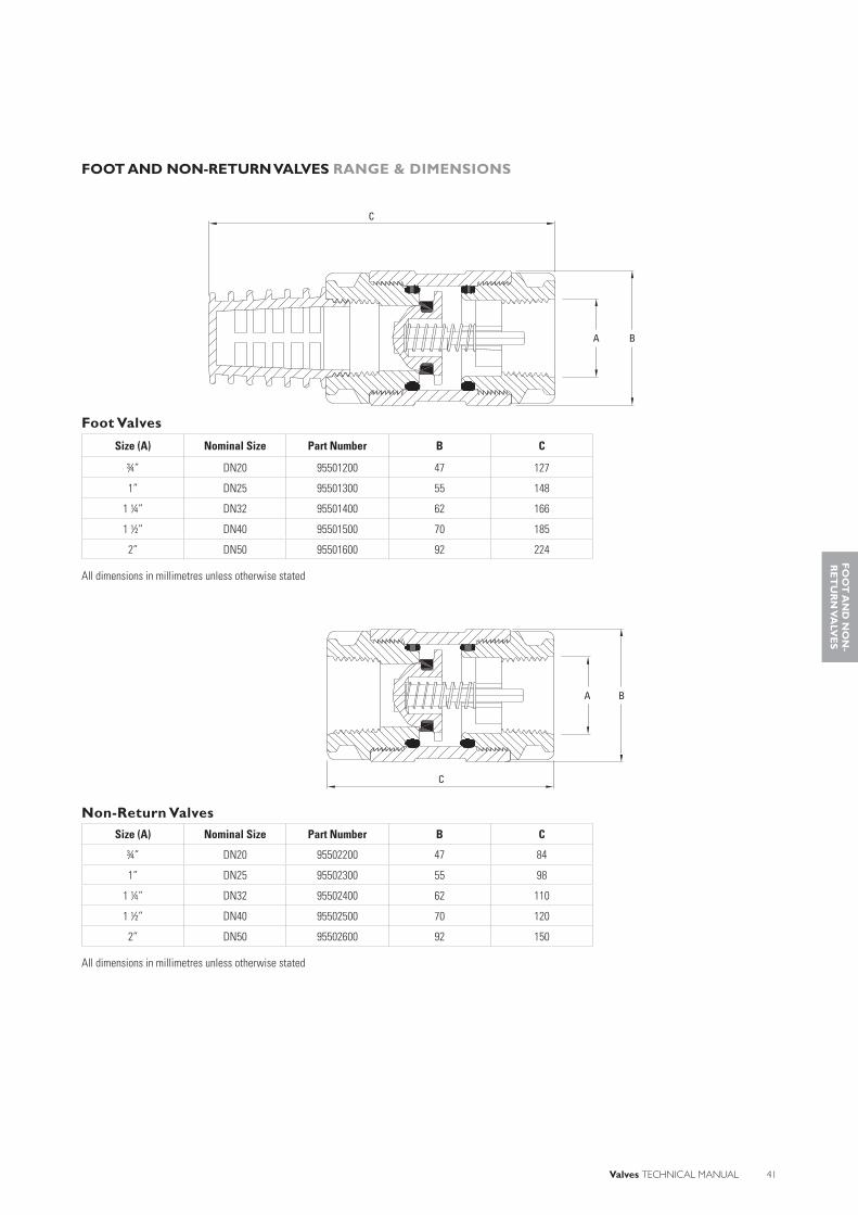
FOOT AND NON-RETURN VALVES RANGE & DIMENSIONS
Foot Valves
Size (A) Nominal Size Part Number B C
¾” DN20 95501200 47 127
1” DN25 95501300 55 148
1 ¼” DN32 95501400 62 166
1 ½” DN40 95501500 70 185
2” DN50 95501600 92 224
All dimensions in millimetres unless otherwise stated
Non-Return ValvesSize (A) Nominal Size Part Number B C
¾” DN20 95502200 47 84
1” DN25 95502300 55 98
1 ¼” DN32 95502400 62 110
1 ½” DN40 95502500 70 120
2” DN50 95502600 92 150
All dimensions in millimetres unless otherwise stated
C
BA
BA
C
FO
OT
AN
D N
ON
-R
ET
UR
N V
ALV
ES

42 Valves TECHNICAL MANUAL
RATIO PRESSURE REDUCING VALVES
Philmac’s ratio pressure reducing valves are designed to control service line pressure in fi xed head water systems and have been doing so for over 40 years.
Their simple yet effective operation means they can protect downstream pipe work, fi ttings and appliances from the effects of excess water pressure. With a fi xed non-adjustable ratio it means the valve does not require adjusting and is tamper proof.
Ratio valves are manufactured from high grade materials to provide reliable operation and a high level of corrosion resistance. Not only are spare parts available but these valves are backed by a full maintenance service.
Philmac’s range of ratio valves are designed to handle situations where reliable, controlled high pressure operation is essential.
Fast and Easy Installation• Minimum Space Required for
Installation: Ratio valves have a compact body design which makes them perfect for tight applications such as fi re services They can be installed in any orientation.
• BSP Inlet Threads: The Industrial and Plumbing sectors use British Standard Pipe (BSP) threads as a standard. Philmac also uses these thread types across the screwed ratio valve range to ensure compatibility with other threaded fi ttings and make installation simple.
• Flanged Inlet/Outlet: To make installation easy Philmac also offer a fl anged ratio valve. The standard drill hole pattern is Table E, however to assist with different installations they are also available with DIN, ANSI 150, Table C/D/F/H, JIS or BS4504 Table II drill hole patterns. Other fl ange patterns can be supplied on request.
• Serviceable: The valves have been designed to be fully serviced and repair kits containing all the seals, o-rings and instructions are readily available. Philmac also offers a servicing facility where the valves are fully disassembled, cleaned, all parts are checked dimensionally and replaced as necessary. The valve is then reassembled with new seals and o-rings and tested to ensure it works at its designated ratio.
Complete Security• Warranty: For peace of mind the
fl anged ratio valves carry a fi ve (5) year warranty on materials and workmanship when used with potable water.
• Simple Sealing Action: Because the valve relies on only one moving part it means high reliability and shutoff when required. There are no internal ports which can become blocked or springs that can become corroded.
• Maintained Pressure: Under no fl ow conditions the downstream pressure is maintained because the valve remains closed and it will not open until the downstream pressure drops when installed in a fi xed head system.
• Corrosion Resistant: With a DZR brass body (screwed) or bronze body (fl anged), 316 stainless steel seat and piston, DZR brass or gunmetal components, nitrile O-rings and seals ensures years of reliable operation.
• Approvals: All valves comply with Australian/New Zealand Standard 4020 which means the valves are suitable for use with drinking water.
• Tamper Proof: There are no external regulators or pilot tubes which can be tampered with so once the valve is installed it will continue to operate at its pre-set ratio.
High Performance• Manufactured from DZR brass: The
brass components in Philmac screwed ratio valves are manufactured from dezincifi cation resistant (DZR) brass. This means the brass is resistant in soil and water environments to corrosion involving the loss of zinc leaving a residue of spongy or porous copper.
• Manufactured from Gunmetal: The fl anged ratio valves are manufactured from a cast gunmetal to provide overall strength in particular the fl ange of the valve.
• High pressure shutoff: Ratio pressure reducing valves are rated to a pressure of 3500 kPa (500 psi) or 35 bar (static shutoff) at 200 Celsius to meet the requirements of high pressure systems.
• High Flow Rates: Due to the internal design, when the valve is fully open it is allows full fl ow of water.
Complete Coverage• Wide range: The range of ratio pressure
reducing valves is comprehensive and includes screwed sizes from ½” to 2” (DN15 to DN50) and fl anged sizes from 2” to 6” (DN50 to DN150). Some body sizes are available with different fl ange sizes (refer to the section on Dimensions).
BENEFITS
Agriculture: Water tanks and troughs on high pressure systems.
Plumbing: Water supply for fi re and potable water from top of buildings down.
Mining: Water supply down mineshafts.
APPLICATIONS

Valves TECHNICAL MANUAL 43
Philmac’s range of ratio valves are
designed to comply with the following
standards and undertake a range of
tests to ensure they comply with these
standards.
StandardsAS/NZ 4020: Testing of products for use
in contact with drinking water.
AS 1722.1: Pipe threads of Whitworth
form part 1: sealing pipe threads..
AS 2129/AS 4087/ANSI 150: Flanges
(Other fl ange specifi cations on request).
ISO7: Pipe threads where pressure tight
joints are made on the threads.
TestsShut Off Test: Valves are tested for shut
off against a hydrostatic water pressure of
3500 kPa (500 psi) or 35 bar.
STANDARDS & TESTS
RA
TIO
PR
ES
SU
RE
R
ED
UC
ING
VA
LVE
S

44 Valves TECHNICAL MANUAL
CLOSED (No Flow) OPEN (Flow)
The valve operates on the principle of differing surface areas. In the example of a 2:1 screwed-ratio valve the upstream piston surface
area is half that of the downstream surface area. Other ratios are obtained by altering the area relationship of the valve.
Under no fl ow conditions the piston is closed to ensure the downstream pressure does not exceed the prescribed ratio.
BODYO-RING
SEATSEAT WASHER
INLET PLUGPISTONOUTLET PLUGO-RING
BODYO-RING
SEATSEAT WASHER
INLET PLUGPISTONOUTLET PLUGO-RING
RATIO PRESSURE REDUCING VALVES OPERATION & INSTALLATION INSTRUCTIONS
A
B
C
D
E80m
20m
60m
50m
150m
The schematic diagram shows an example installation and how
ratio valves effectively reduce pressure to ensure the rating of
pipework is not exceeded. Pressure after the valves will vary
depending on ratio being used. Water is fed by gravity from a
header tank into the system. Each fl anged ratio valve should
have an isolating valve installed both upstream and downstream
to allow it to be removed for servicing.
From the tank to the fi rst ratio valve the pressure will increase
to approximately 1500 kPa at point A if we assume the tank is
3 metres high (150 m drop + 3 m tank height x 9.8). After the
ratio valve the pressure will drop to 500 kPa (1500 ÷ 3) if we
assume a 3:1 ratio is being used. Pressure will then build up to
approximately 990 kPa (50 m x 9.8 plus the starting pressure
of 500 kPa) at point B and 1580 kPa at point C as water moves
down the pipe.
After point C the pressure will drop to approximately 395 kPa
(1580 ÷ 4) if we assume a 4:1 ratio valve is being used. At
point D the pressure will increase to approximately 590 kPa
and approximately 1375 kPa at point E.

Valves TECHNICAL MANUAL 45
RATIO PRESSURE REDUCING VALVES OPERATION & INSTALLATION INSTRUCTIONS
Valves must be installed according to the direction of fl ow as indicated on the valve. They can be installed vertically or horizontally but it
is important that the breather hole is visible. It is critical that the breather hole kept free from obstructions and if buried the hole must
be protected from blockage.
1. Apply PTFE tape or approved sealant to the thread ensuring suffi cient is applied to ensure a watertight seal.
1. Ensure a gasket is used between the fl ange of the ratio valve and the fl ange to which it is to be fi tted.
2. Screw into male thread by hand until fi rm.
2. Fit the correct size and length bolts to each hole in the fl ange and hand tighten them.
3. Using a pipe wrench or multigrips on the hex end of the valve, screw it into the male thread until tight. Where necessary ensure the male thread is held stationary to avoid it from moving.
3. Tighten the bolts with a spanner ensuring the bolts are torqued up correctly in an appropriate sequence.
Screwed Version
Flanged Version
RA
TIO
PR
ES
SU
RE
R
ED
UC
ING
VA
LVE
S
1
2
3
45
6
FIGURE 1
Note: When assembling a fl anged adaptor, position the gasket and loosely assemble the fi tting. Tighten bolts gradually in sequence shown numerically in Figure 1, to ensure even compression around the fl ange. Ensure washers are used under bolt heads and nuts.

46 Valves TECHNICAL MANUAL
SYSTEM DESIGN CONSIDERATIONS
Minimum Inlet Pressure: 200 kPa
(29 psi) or 2 bar on screwed range and
300 kPa (43 psi) or 3 bar on fl anged
range
Maximum Inlet Pressure: 3500 kPa
(500 psi) on 35 bar.
Threads: All threads on the screwed
ratio valves are BSP with a Whitworth
form.
Flanges: All fl anges on the fl anged ratio
valves are drilled according to Table E.
Dimensions as per AS2129. Other fl ange
types are available on request including DIN, ANSI 150, Table C/D/F/H, JIS or
BS4504 Table II.
Sealing threads: Philmac recommends
sealing threads with PTFE tape. When
being fi tted to a metal thread an
approved metal sealant can be used.
Operating temperature: Connection is
cold water (less than 200C) rated.
Weathering: All non-ferrous materials are
protected from the affects of UV.
Pressure Reduction: The inlet pressure is
reduced as per the ratio of the valve and
will hold the downstream pressure to
with +/- 5% of the inlet pressure.
Ratios: Screwed – 2:1 & 3:1
Flanged – 3:2, 2:1, 3:1, 4:1 & 5:1
Isolating valves: An isolating valve
should be installed both upstream and
downstream of a ratio valve to allow it to
be removed for servicing. Consideration
should be given to installing two valves in
parallel to allow one to be removed for
servicing.
Flow Rates* (L/min) - Screwed
Inlet Pressure
(kPa)
Inlet Size
½”(DN15)
¾”(DN20)
1”(DN25)
1 ½”(DN40)
2”(DN50)
200 25 30 75 375 530
300 30 35 95 470 660
500 40 45 125 605 850
1000 55 65 175 660 1205
1500 70 80 210 1050 1480
2000 80 90 245 1215 1705
2500 85 100 275 1355 1910
3000 95 110 300 1485 2090
3500 100 120 325 1605 2260
* Theoretical maximum water flow rate when outlet is open ended
Flow Rates* (L/min) - Flanged
Inlet Pressure
(kPa)
Inlet Size
2”(DN50)
3”(DN80)
4”(DN100)
6”(DN150)
300 1350 3100 5650 13400
500 1700 4000 7100 17500
1000 2500 5600 10000 24800
1500 3000 6900 12000 30000
2000 3500 7900 14000 34700
2500 3800 8800 15700 38700
3000 4200 9700 17300 42500
3500 4600 10500 18600 46000
* Theoretical maximum water flow rate when outlet is open ended
CHEMICAL RESISTANCE
Philmac’s ratio pressure reducing valves are primarily designed to convey water. However there may be occasions where the water contains chemicals and/or alternative fl uids need to be controlled. The following table is provided as a guide only for the compatibility of various chemicals and/or alternative fl uids to Philmac ratio valves. The mixing of chemicals may affect the compatibility.
Chemical Ratio valveAcetic acid (10%) NAcetic acid (50%) NAlcohol (ethanol) NAmmonium nitrate NAntifreeze RBrine NCalcium carbonateCalcium chloride NCalcium nitrateCalcium sulphateChlorine water NCitric Acid NCopper Sulphate >5% NDiesel (fuel) REthyl alcohol (ethanol) NHydrochloric acid (10%) NHydrochloric acid (30%) NKerosene RLubricating oils (not synthetic) RMagnesium nitrateMagnesium sulphate RMineral oils RNitric acid (10%) NNitric acid (40%) NOlive oilOrange juicePetrolPhosphoric acid (85%) NDrinking water RPotassium chloride NPotassium nitrate RPotassium sulphate NSodium bicarbonate NSodium hypochlorite (<10%)Sulphuric acid (10%)Sulphuric acid (30%)UreaZinc nitrateZinc sulphate R
N = Not RecommendedR = ResistantEmpty Cell = No data availableNote recommendations based on fl uids at 200 C or less

Valves TECHNICAL MANUAL 47
RATIO PRESSURE REDUCING VALVES MATERIAL & COMPONENTS
Screwed Ratio ValvesSize Nominal
SizePart
NumberRatio Body Inlet Plug Outlet Plug Piston Seat Seat Seal O-Ring
½” DN15 90222100 2:1 DZR brass DZR brass DZR brass DZR brass 316 SS Nitrilerubber
Nitrilerubber90223100 3:1
¾” DN20 90222200 2:1 DZR brass DZR brass DZR brass DZR brass 316 SS Nitrilerubber
Nitrilerubber90223200 3:1
1” DN25 90222300 2:1 DZR brass DZR brass DZR brass DZR brass 316 SS Nitrilerubber
Nitrilerubber90223300 3:1
1 ½” DN40 90222500 2:1 DZR brass DZR brass DZR brass DZR brass 316 SS Nitrilerubber
Nitrilerubber90223500 3:1
2” DN50 90222600 2:1 DZR brass DZR brass DZR brass DZR brass 316 SS Nitrilerubber
Nitrilerubber90223600 3:1
BODY
O-RING
SEAT
SEAT WASHER
INLET PLUG
PISTON
OUTLET PLUG
O-RING
RA
TIO
PR
ES
SU
RE
R
ED
UC
ING
VA
LVE
S

48 Valves TECHNICAL MANUAL
Flanged Ratio Valves BodySize
Flange Size
Table Pattern
Body Sleeve Piston Ring Seat Retainer
Bush Locking
SeatRetainer
Seat Seal O-ring
2” (50) 2” (50) D/E Gunmetal LG2
Gunmetal 316 S/S Gunmetal Gunmetal Gunmetal Nitrile rubber
Nitrile rubber
2” (50) 2 ½” (65) D/E Gunmetal LG2
Gunmetal 316 S/S Gunmetal Gunmetal Gunmetal Nitrile rubber
Nitrile rubber
3” (80) 3” (80) D/E Gunmetal LG2
Gunmetal 316 S/S Gunmetal Gunmetal Gunmetal Nitrile rubber
Nitrile rubber
3” (80) 4” (100) E Gunmetal LG2
Gunmetal 316 S/S Gunmetal Gunmetal Gunmetal Nitrile rubber
Nitrile rubber
4” (100) 4” (100) E Gunmetal LG2
Gunmetal 316 S/S Gunmetal Gunmetal Gunmetal Nitrile rubber
Nitrile rubber
4” (100) 6” (150) E Gunmetal LG2
Gunmetal 316 S/S Gunmetal Gunmetal Gunmetal Nitrile rubber
Nitrile rubber
6” (150) 6” (150) E Gunmetal LG2
Gunmetal 316 S/S Gunmetal Gunmetal Gunmetal Nitrile rubber
Nitrile rubber
NOTE: Part numbers and ratios are not shown due to the number of variations available.
O-RING
BODY
SLEEVE
O-RING
BUSH LOCKING
PISTON
O-RING
O-RING
SEAT WASHER
RING SEAT RETAINER
SEAT RETAINER
INLET
RATIO PRESSURE REDUCING VALVES MATERIAL & COMPONENTS

Valves TECHNICAL MANUAL 49
RATIO PRESSURE REDUCING VALVES RANGE & DIMENSIONS
Screwed Ratio ValveSize(A)
Nominal Size
B C
½” DN15 38 80
¾” DN20 45 96
1” DN25 51 107
1 ½” DN40 95 155
2” DN50 118 160
All dimensions in millimetres unless otherwise stated
Flanged Ratio ValveBody Size(A)
Nominal BodySize
Flange Size
Nominal Flange
Size
B* C* D
2” DN50 2” 50 150 114 135
2” DN50 2 ½” 65 165 127 135
2” DN50 3” 80 185 146 135
3” DN80 3” 80 185 146 155
3” DN80 4” 100 215 178 200
4” DN100 4” 100 215 178 200
4” DN100 6” 150 280 235 230
6” DN150 6” 150 280 235 230
* Dimensions based on a Table E flange configurationAll dimensions in millimetres unless otherwise stated
BA
C
BCA
D
RA
TIO
PR
ES
SU
RE
R
ED
UC
ING
VA
LVE
S
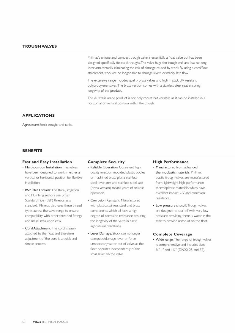
50 Valves TECHNICAL MANUAL
TROUGH VALVES
Philmac’s unique and compact trough valve is essentially a fl oat valve but has been
designed specifi cally for stock troughs. The valve hugs the trough wall and has no long
lever arm, virtually eliminating the risk of damage caused by stock. By using a cord/fl oat
attachment, stock are no longer able to damage levers or manipulate fl ow.
The extensive range includes quality brass valves and high impact, UV resistant
polypropylene valves. The brass version comes with a stainless steel seat ensuring
longevity of the product.
This Australia made product is not only robust but versatile as it can be installed in a
horizontal or vertical position within the trough.
Fast and Easy Installation• Multi-position Installation: The valves
have been designed to work in either a
vertical or horizontal position for fl exible
installation.
• BSP Inlet Threads: The Rural, Irrigation
and Plumbing sectors use British
Standard Pipe (BSP) threads as a
standard. Philmac also uses these thread
types across the valve range to ensure
compatibility with other threaded fi ttings
and make installation easy.
• Cord Attachment: The cord is easily
attached to the fl oat and therefore
adjustment of the cord is a quick and
simple process.
Complete Security• Reliable Operation: Consistent high
quality injection moulded plastic bodies
or machined brass plus a stainless
steel lever arm and stainless steel seat
(brass version) means years of reliable
operation.
• Corrosion Resistant: Manufactured
with plastic, stainless steel and brass
components which all have a high
degree of corrosion resistance ensuring
the longevity of the valve in harsh
agricultural conditions.
• Lever Damage: Stock can no longer
stampede/damage lever or force
unnecessary water out of valve, as the
fl oat operates independently of the
small lever on the valve.
High Performance• Manufactured from advanced
thermoplastic materials: Philmac
plastic trough valves are manufactured
from lightweight high performance
thermoplastic materials, which have
excellent impact, UV and corrosion
resistance.
• Low pressure shutoff: Trough valves
are designed to seal off with very low
pressure providing there is water in the
tank to provide upthrust on the fl oat.
Complete Coverage• Wide range: The range of trough valves
is comprehensive and includes sizes
¾", 1" and 1¼" (DN20, 25 and 32).
BENEFITS
Agriculture: Stock troughs and tanks.
APPLICATIONS
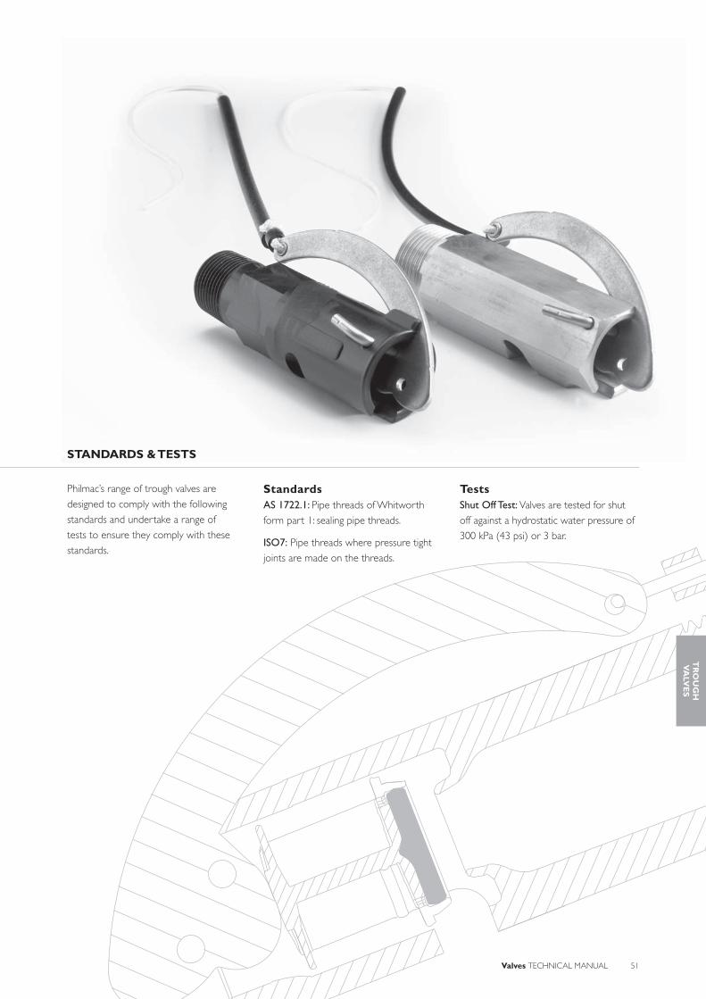
Valves TECHNICAL MANUAL 51
Philmac’s range of trough valves are
designed to comply with the following
standards and undertake a range of
tests to ensure they comply with these
standards.
StandardsAS 1722.1: Pipe threads of Whitworth
form part 1: sealing pipe threads.
ISO7: Pipe threads where pressure tight
joints are made on the threads.
TestsShut Off Test: Valves are tested for shut
off against a hydrostatic water pressure of
300 kPa (43 psi) or 3 bar.
STANDARDS & TESTS
TR
OU
GH
VA
LVE
S

52 Valves TECHNICAL MANUAL
TROUGH VALVES OPERATION & INSTALLATION INSTRUCTIONS
The Philmac trough valves operate by opening and closing a plunger against a seat through the action of a lever attached to a fl oat. As
the water level drops, the fl oat and lever move in a downward direction and the plunger moves away from the seat opening the valve.
When the water level rises, the fl oat and lever move in an upwards direction and the plunger moves towards the seat until it sits fi rmly
against the seat and shuts the valve off.
1. Apply PTFE tape or approved sealant to the thread ensuring suffi cient is applied to ensure a watertight seal.
1. For overhead installation the lever needs to be relocated by unscrewing the pin from the body.
1. Insert the cord through bottom hole of the fl oat, ensure the top of the fl oat is BELOW the rim of the trough then place the cord around the right hand lug. Make a loop.
2. Twist the loop. 3. Place it over the left hand lug and pull tight.
2. Screw into female thread by hand until fi rm.
2. Rotate the lever by 180° and reinsert the pin through the lower hole (upper hole is for the standard installation). (Refer page 54 for pin locations).
3. Using a pipe wrench or multigrips on the body of the valve screw it into the female thread until tight. Where necessary ensure the female thread is held stationary to avoid it from moving.
3. Installation position.
Setting the Float
Conversion for Overhead Entry

Valves TECHNICAL MANUAL 53
SYSTEM DESIGN CONSIDERATIONS
Maximum Operating Pressure: 400 kPa
(58 psi) (¾” brass only) and 300 kPa (43
psi) at 200C.
Threads: All threads are BSP (Whitworth
form).
Sealing threads: Philmac recommends
sealing threads with PTFE tape. Other
approved sealants for plastic or brass
materials can be used providing the
sealant does not enter the valve where it
may cause damage.
Operating temperature: Connection is
cold water (less than 200C) rated.
Weathering: All plastic materials used
contain pigments to provide excellent
protection against degradation from
ultra-violet (UV) radiation. However
long-term continuous exposure to
UV is not recommended and plastic
components should ideally be protected.
Flow Rates (L/min)
Inlet Pressure
(kPa)
Inlet Size
¾” Brass (DN20)
¾” Plastic (DN20)
1” Plastic(DN25)
1” Brass(DN25)
1 ¼” Brass (DN32)
1 ¼” Plastic (DN32)
25 32 33 33 37 57 60
50 38 42 42 48 70 76
75 46 49 49 58 85 92
100 53 57 57 67 99 108
150 64 70 70 83 121 132
200 74 82 82 96 140 154
250 83 91 91 106 157 172
300 91 100 100 114 175 187
400 106 - - - - -
CHEMICAL RESISTANCE
Philmac’s trough valves are primarily designed
to convey water. However there may
be occasions where the water contains
chemicals and/or alternative fl uids need to
be controlled. The following table is provided
as a guide only for the compatibility of
various chemicals and/or alternative fl uids to
Philmac trough valves. The mixing together
of chemicals may affect the compatibility.
Chemical
CompatibilityTroughValve
- Plastic
TroughValve
- BrassAcetic acid (10%) R NAcetic acid (50%) N NAlcohol (ethanol) N NAmmonium nitrate R NAntifreeze R RBrine R NCalcium carbonate RCalcium chloride N NCalcium nitrate NCalcium sulphate NChlorine water N NCitric Acid N NCopper Sulphate >5% N NDiesel (fuel) R REthyl alcohol (ethanol) N NHydrochloric acid (10%) N NHydrochloric acid (30%) N NKerosene R RLubricating oils (not synthetic) R RMagnesium nitrate RMagnesium sulphate R RMineral oils R RNitric acid (10%) N NNitric acid (40%) N NOlive oil NOrange juice RPetrol RPhosphoric acid (85%) N NDrinking water R RPotassium chloride R RPotassium nitrate R RPotassium sulphate RSodium bicarbonate RSodium hypochlorite (<10%) N NSulphuric acid (10%) N NSulphuric acid (30%) N NUrea R RZinc nitrate NZinc sulphate N
N = Not RecommendedR = ResistantEmpty Cell = No data availableNote recommendations based on fl uids at 200 C or less
TR
OU
GH
VA
LVE
S
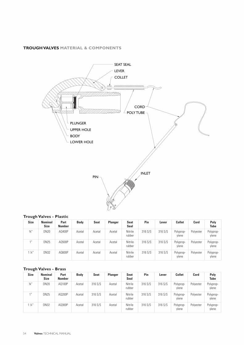
54 Valves TECHNICAL MANUAL
TROUGH VALVES MATERIAL & COMPONENTS
Trough Valves - PlasticSize Nominal
SizePart
NumberBody Seat Plunger Seat
SealPin Lever Collet Cord Poly
Tube
¾” DN20 AQ400P Acetal Acetal Acetal Nitrile rubber
316 S/S 316 S/S Polyprop-ylene
Polyester Polyprop-ylene
1” DN25 AQ500P Acetal Acetal Acetal Nitrile rubber
316 S/S 316 S/S Polyprop-ylene
Polyester Polyprop-ylene
1 ¼” DN32 AQ600P Acetal Acetal Acetal Nitrile rubber
316 S/S 316 S/S Polyprop-ylene
Polyester Polyprop-ylene
Trough Valves - BrassSize Nominal
SizePart
NumberBody Seat Plunger Seat
SealPin Lever Collet Cord Poly
Tube
¾” DN20 AQ100P Acetal 316 S/S Acetal Nitrile rubber
316 S/S 316 S/S Polyprop-ylene
Polyester Polyprop-ylene
1” DN25 AQ200P Acetal 316 S/S Acetal Nitrile rubber
316 S/S 316 S/S Polyprop-ylene
Polyester Polyprop-ylene
1 ¼” DN32 AQ300P Acetal 316 S/S Acetal Nitrile rubber
316 S/S 316 S/S Polyprop-ylene
Polyester Polyprop-ylene
SEAT SEAL
CORD
PLUNGER
UPPER HOLE
LOWER HOLE
PIN
BODY
POLY TUBE
LEVER
COLLET
INLET
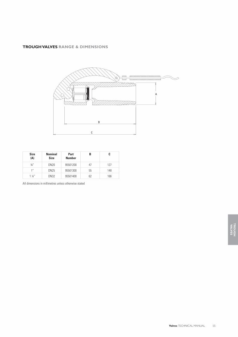
Valves TECHNICAL MANUAL 55
TROUGH VALVES RANGE & DIMENSIONS
Size(A)
Nominal Size
Part Number
B C
¾” DN20 95501200 47 127
1” DN25 95501300 55 148
1 ¼” DN32 95501400 62 166
All dimensions in millimetres unless otherwise stated
B
C
A
TR
OU
GH
VA
LVE
S
56 Valves TECHNICAL MANUAL
HIGH FLOW FLOAT VALVE
Philmac’s high fl ow fl oat valves have been developed to meet the industry demand for a
high capacity valve. Based on a simple movement of a fl apper, the valves can deliver high
volumes of water in a short period of time.
Their compact design means they are quick and easy to install and ensure a constant
water level is maintained in the trough.
With a heavy duty brass construction Philmac’s range of high fl ow fl oat valves are
designed to handle the most demanding livestock and agricultural situations.
Fast and Easy Installation• Easy Disassembly: The valves have been
designed for easy replacement of the
rubber seal. Simply remove the cotter
pins and clevis pins to access the fl apper
and seal.
• BSP Inlet Threads: The Rural, Irrigation
and Plumbing sectors use British
Standard Pipe (BSP) threads as a
standard. Philmac also uses these thread
types across the valve range to ensure
compatibility with other threaded fi ttings
and make installation easy.
Complete Security• Reliable Operation: Consistent high
quality brass bodies plus a stainless steel
seat and brass components means years
of reliable operation.
• Corrosion Resistant: Manufactured
using rubber, stainless steel and brass
components ensures the valves have
a high corrosion resistance, providing
years of reliable operation.
High Performance• Low pressure shutoff: High fl ow fl oat
valves are designed to seal off with very
low pressure providing there is water
in the tank to provide upthrust on the
fl oat.
• High pressure shutoff: Some versions of
the high fl ow fl oat valves are designed
to seal off with high pressure making
the valve suitable for a wider range of
applications.
Complete Coverage• Wide range: The range of high fl ow
fl oat valves is comprehensive and
includes sizes from 1” to 2” (DN25 to
DN50).
BENEFITS
APPLICATIONS
Agriculture: Stock troughs.

Valves TECHNICAL MANUAL 57
Philmac’s range of high fl ow fl oat valves
are designed to comply with the following
standards and undertake a range of
tests to ensure they comply with these
standards.
StandardsAS 1722.1: Pipe threads of Whitworth
form part 1: sealing pipe threads.
ISO7: Pipe threads where pressure tight
joints are made on the threads.
TestsShut Off Test: Valves are tested for shut off
against their maximum shut off pressure.
STANDARDS & TESTS
HIG
H F
LO
WF
LO
AT
VA
LVE
S
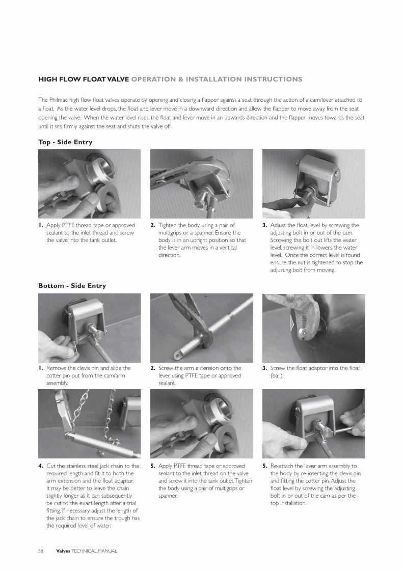
58 Valves TECHNICAL MANUAL
HIGH FLOW FLOAT VALVE OPERATION & INSTALLATION INSTRUCTIONS
The Philmac high fl ow fl oat valves operate by opening and closing a fl apper against a seat through the action of a cam/lever attached to
a fl oat. As the water level drops, the fl oat and lever move in a downward direction and allow the fl apper to move away from the seat
opening the valve. When the water level rises, the fl oat and lever move in an upwards direction and the fl apper moves towards the seat
until it sits fi rmly against the seat and shuts the valve off.
1. Apply PTFE thread tape or approved sealant to the inlet thread and screw the valve into the tank outlet.
2. Tighten the body using a pair of multigrips or a spanner. Ensure the body is in an upright position so that the lever arm moves in a vertical direction.
3. Adjust the fl oat level by screwing the adjusting bolt in or out of the cam. Screwing the bolt out lifts the water level, screwing it in lowers the water level. Once the correct level is found ensure the nut is tightened to stop the adjusting bolt from moving.
Top - Side Entry
1. Remove the clevis pin and slide the cotter pin out from the cam/arm assembly.
4. Cut the stainless steel jack chain to the required length and fi t it to both the arm extension and the fl oat adaptor. It may be better to leave the chain slightly longer as it can subsequently be cut to the exact length after a trial fi tting. If necessary adjust the length of the jack chain to ensure the trough has the required level of water.
2. Screw the arm extension onto the lever using PTFE tape or approved sealant.
5. Apply PTFE thread tape or approved sealant to the inlet thread on the valve and screw it into the tank outlet. Tighten the body using a pair of multigrips or spanner.
5. Re-attach the lever arm assembly to the body by re-inserting the clevis pin and fi tting the cotter pin. Adjust the fl oat level by screwing the adjusting bolt in or out of the cam as per the top installation.
3. Screw the fl oat adaptor into the fl oat (ball).
Bottom - Side Entry

Valves TECHNICAL MANUAL 59
SYSTEM DESIGN CONSIDERATIONS
Maximum Operating Pressure: At 200C
1" – 620 kPa (90 psi) or 6.2 bar
1¼" – 620 kPa (90 psi) or 6.2 bar
1½" LP – 205 kPa (30 psi) or 2 bar
1½" HP – 620 kPa (90 psi) or 6.2 bar
2" LP – 105 kPa (15 psi) or 1 bar
2" HP – 485 kPa (70 psi) or 4.8 bar.
Threads: All threads are BSP (Whitworth
form).
Sealing threads: Philmac recommends
sealing threads with PTFE tape. Other
approved sealants for brass materials can
be used providing the sealant does not
enter the valve where it may cause damage.
Operating temperature: Connection is
cold water (less than 200C) rated.
Weathering: Brass components are UV
resistant
Flow Rates (L/min)
Inlet Pressure
(kPa)
Inlet Size
1” & 1 ¼”(DN25 & DN32)
1½” HP*(DN40)
1½” LP**(DN40)
2” HP* (DN50)
2” LP** (DN50)
15 - - 175 - 177
25 100 108 219 100 225
50 115 126 294 132 330
75 144 159 - 160 -
100 168 174 - 186 -
150 205 222 - 234 -
200 235 258 - 249 -
250 265 288 - 258 -
300 290 300 - 276 -
* HP denotes high pressure version** LP denotes low pressure version
CHEMICAL RESISTANCE
Philmac’s high fl ow fl oat valves are designed
to convey water for stock. However there
may be occasions where the water contains
chemicals and/or alternative fl uids need to be
controlled. The following table is provided as
a guide only for the compatibility of various
chemicals and/or alternative fl uids to Philmac
high fl ow fl oat valves. The mixing together of
chemicals may affect the compatibility.
Chemical CompatibilityAcetic acid (10%) NAcetic acid (50%) NAlcohol (ethanol) NAmmonium nitrate NAntifreeze RBrine NCalcium carbonateCalcium chloride NCalcium nitrateCalcium sulphateChlorine water NCitric Acid NCopper Sulphate >5% NDiesel (fuel) REthyl alcohol (ethanol) NHydrochloric acid (10%) NHydrochloric acid (30%) NKerosene RLubricating oils (not synthetic) RMagnesium nitrateMagnesium sulphate RMineral oils RNitric acid (10%) NNitric acid (40%) NOlive oil NOrange juicePetrolPhosphoric acid (85%) NDrinking water RPotassium chloride NPotassium nitrate RPotassium sulphate NSodium bicarbonate NSodium hypochlorite (<10%) NSulphuric acid (10%)Sulphuric acid (30%)UreaZinc nitrateZinc sulphate R
N = Not RecommendedR = ResistantEmpty Cell = No data availableNote recommendations based on fl uids at 200 C or less
HIG
H F
LO
WF
LO
AT
VA
LVE
S

60 Valves TECHNICAL MANUAL
HIGH FLOW FLOAT VALVE MATERIAL & COMPONENTS
COTTER PIN
FLOAT
FLAPPERSEAT
SEAT SEALCLEVIS PIN
NUTBOLT
LEVERCAMBODY
FLOATFLOAT ADAPTORCHAINARM EXTENSION
Size Nominal Size Part Number Body Seat Seat Seal Flapper Clevis Pins Cotter Pins
1” DN25 90322300 Brass 316 S/S Brass Brass 316 S/S 316 S/S
1 ¼” DN32 90322400 Brass 316 S/S Brass Brass 316 S/S 316 S/S
1 ½” LP DN40 90322500 Brass 316 S/S Brass Brass 316 S/S 316 S/S
1 ½” HP DN40 90322501 Brass 316 S/S Brass Brass 316 S/S 316 S/S
2” LP DN50 90322600 Brass 316 S/S Brass Brass 316 S/S 316 S/S
2” HP DN50 90322601 Brass 316 S/S Brass Brass 316 S/S 316 S/S
Size Nominal Size Nut & Bolt Cam Lever Adaptor Float Adaptor Chain Float
1” DN25 Brass Brass Brass Brass Brass 316 S/S Polyethylene
1 ¼” DN32 Brass Brass Brass Brass Brass 316 S/S Polyethylene
1 ½” LP DN40 Brass Brass Brass Brass Brass 316 S/S Polyethylene
1 ½” HP DN40 Brass Brass Brass Brass Brass 316 S/S Polyethylene
2” LP DN50 Brass Brass Brass Brass Brass 316 S/S Polyethylene
2” HP DN50 Brass Brass Brass Brass Brass 316 S/S Polyethylene

Valves TECHNICAL MANUAL 61
HIGH FLOW FLOAT VALVE RANGE & DIMENSIONS
Size (A) Nominal Size B C D* E F G
1” DN25 70 19 615 225 370 63
1¼” DN32 70 19 615 225 370 63
1½” LP DN40 80.5 37 618 225 370 78
1½” HP DN40 80.5 19 618 225 370 78
2” LP DN50 90 47 619 225 370 85
2” HP DN50 90 19 619 225 370 85
All dimensions in millimetres unless otherwise stated* Approximate. It will vary depending on how the bolt is adjusted.
B A
F
D
E
G
C
HIG
H F
LO
WF
LO
AT
VA
LVE
S
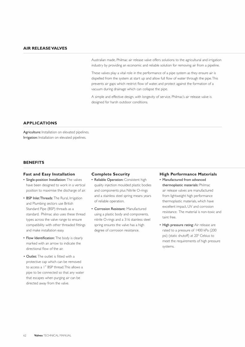
62 Valves TECHNICAL MANUAL
AIR RELEASE VALVES
Australian made, Philmac air release valve offers solutions to the agricultural and irrigation
industry by providing an economic and reliable solution for removing air from a pipeline.
These valves play a vital role in the performance of a pipe system as they ensure air is
dispelled from the system at start up and allow full fl ow of water through the pipe. This
prevents air gaps which restrict fl ow of water, and protect against the formation of a
vacuum during drainage which can collapse the pipe.
A simple and effective design, with longevity of service, Philmac’s air release valve is
designed for harsh outdoor conditions.
Fast and Easy Installation• Single-position Installation: The valves
have been designed to work in a vertical
position to maximise the discharge of air.
• BSP Inlet Threads: The Rural, Irrigation
and Plumbing sectors use British
Standard Pipe (BSP) threads as a
standard. Philmac also uses these thread
types across the valve range to ensure
compatibility with other threaded fi ttings
and make installation easy.
• Flow Identifi cation: The body is clearly
marked with an arrow to indicate the
directional fl ow of the air.
• Outlet: The outlet is fi tted with a
protective cap which can be removed
to access a 1“ BSP thread. This allows a
pipe to be connected so that any water
that escapes when purging air can be
directed away from the valve.
Complete Security• Reliable Operation: Consistent high
quality injection moulded plastic bodies
and components plus Nitrile O-rings
and a stainless steel spring means years
of reliable operation.
• Corrosion Resistant: Manufactured
using a plastic body and components,
nitrile O-rings and a 316 stainless steel
spring ensures the valve has a high
degree of corrosion resistance.
High Performance Materials• Manufactured from advanced
thermoplastic materials: Philmac
air release valves are manufactured
from lightweight high performance
thermoplastic materials, which have
excellent impact, UV and corrosion
resistance. The material is non-toxic and
taint free.
• High pressure rating: Air release are
rated to a pressure of 1400 kPa (200
psi) (static shutoff) at 200 Celsius to
meet the requirements of high pressure
systems.
BENEFITS
APPLICATIONS
Agriculture: Installation on elevated pipelines.
Irrigation: Installation on elevated pipelines.
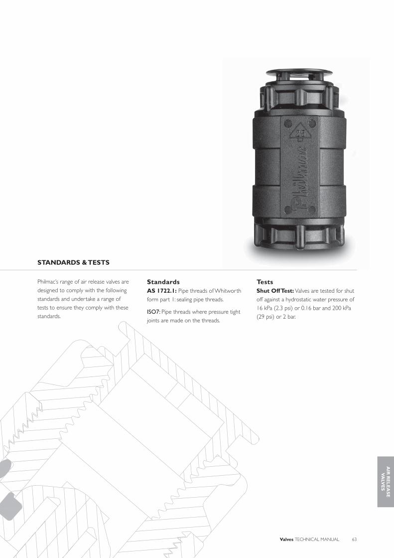
Valves TECHNICAL MANUAL 63
Philmac’s range of air release valves are
designed to comply with the following
standards and undertake a range of
tests to ensure they comply with these
standards.
StandardsAS 1722.1: Pipe threads of Whitworth
form part 1: sealing pipe threads.
ISO7: Pipe threads where pressure tight
joints are made on the threads.
TestsShut Off Test: Valves are tested for shut
off against a hydrostatic water pressure of
16 kPa (2.3 psi) or 0.16 bar and 200 kPa
(29 psi) or 2 bar.
STANDARDS & TESTS
AIR
RE
LE
AS
EV
ALV
ES
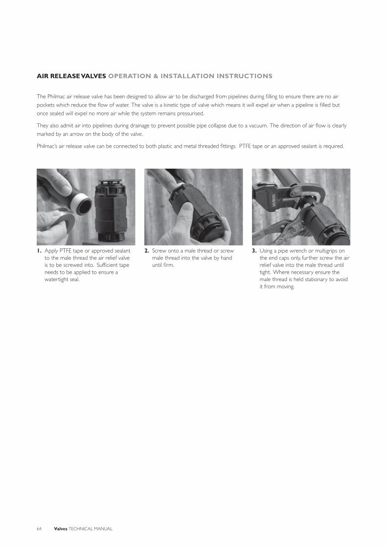
64 Valves TECHNICAL MANUAL
AIR RELEASE VALVES OPERATION & INSTALLATION INSTRUCTIONS
The Philmac air release valve has been designed to allow air to be discharged from pipelines during fi lling to ensure there are no air
pockets which reduce the fl ow of water. The valve is a kinetic type of valve which means it will expel air when a pipeline is fi lled but
once sealed will expel no more air while the system remains pressurised.
They also admit air into pipelines during drainage to prevent possible pipe collapse due to a vacuum. The direction of air fl ow is clearly
marked by an arrow on the body of the valve.
Philmac’s air release valve can be connected to both plastic and metal threaded fi ttings. PTFE tape or an approved sealant is required.
1. Apply PTFE tape or approved sealant to the male thread the air relief valve is to be screwed into. Suffi cient tape needs to be applied to ensure a watertight seal.
2. Screw onto a male thread or screw male thread into the valve by hand until fi rm.
3. Using a pipe wrench or multigrips on the end caps only, further screw the air relief valve into the male thread until tight. Where necessary ensure the male thread is held stationary to avoid it from moving.

Valves TECHNICAL MANUAL 65
SYSTEM DESIGN CONSIDERATIONS
Minimum Sealing Pressure: 20 kPa (3 psi)
or 2 m or 0.2 bar of head at 200C.
Maximum Operating Pressure: 1400 kPa
(200 psi) at 200C.
Threads: All threads are BSP (Whitworth
form).
Sealing threads: Philmac recommends
sealing threads with PTFE tape. Other
approved sealants for plastic materials
can be used providing the sealant does
not enter the valve where it may cause
damage.
Operating temperature: Connection is
cold water (less than 200C) rated.
Weathering: All plastic materials used
contain pigments to provide excellent
protection against degradation from
ultra-violet (UV) radiation. However
long-term continuous exposure to
UV is not recommended and plastic
components should ideally be protected.
CHEMICAL RESISTANCE
Philmac’s air release valve is primarily designed to expel air from water pipelines. However there may be occasions where the water contains chemicals and/or alternative fl uids need to be controlled. The following table is provided as a guide only for the compatibility of various chemicals and/or alternative fl uids to the Philmac air release valve. The mixing together of chemicals may affect the compatibility. The Philmac air release valve is NOT suited for acids.
Chemical CompatibilityAcetic acid (10%) RAcetic acid (50%) NAlcohol (ethanol) NAmmonium nitrate RAntifreeze RBrine RCalcium carbonate RCalcium chloride RCalcium nitrate RCalcium sulphateChlorine water NCitric Acid RCopper Sulphate >5% NDiesel (fuel) REthyl alcohol (ethanol) NHydrochloric acid (10%) NHydrochloric acid (30%) NKerosene RLubricating oils (not synthetic) RMagnesium nitrate RMagnesium sulphate RMineral oils RNitric acid (10%) NNitric acid (40%) NOlive oil ROrange juice RPetrol RPhosphoric acid (85%) NDrinking water RPotassium chloride RPotassium nitrate RPotassium sulphateSodium bicarbonateSodium hypochlorite (<10%) NSulphuric acid (10%) NSulphuric acid (30%) NUrea RZinc nitrate NZinc sulphate
N = Not RecommendedR = ResistantEmpty Cell = No data availableNote recommendations based on fl uids at 200 C or less
AIR
RE
LE
AS
EV
ALV
ES

66 Valves TECHNICAL MANUAL
AIR RELEASE VALVES MATERIAL & COMPONENTS
Size Nominal Size Part Number Body Inlet/Outlet Piston Seal Ring O-rings Cap
1” DN25 95503300 GF Nylon GF Nylon Alloy Acetal Nitrile Nitrile rubber Nylon
CAP
INLET
O-RING
SEAL RING
PISTON
O-RING
BODY
OUTLET
INLET
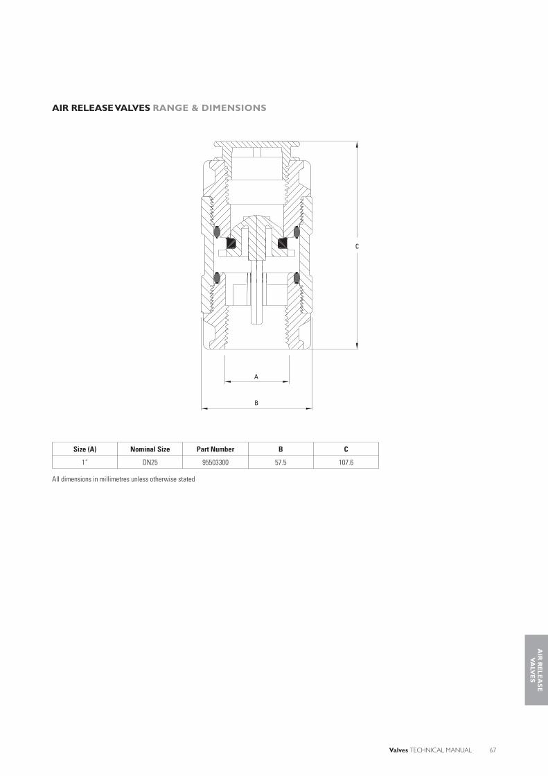
Valves TECHNICAL MANUAL 67
AIR RELEASE VALVES RANGE & DIMENSIONS
Size (A) Nominal Size Part Number B C
1” DN25 95503300 57.5 107.6
All dimensions in millimetres unless otherwise stated
A
B
C
AIR
RE
LE
AS
EV
ALV
ES

68 Valves TECHNICAL MANUAL
FLOATS (BALLS) & ACCESSORIES
Philmac has been manufacturing a range of fl oats and accessories for over 40 years to
support its extensive range of valves. The offering available includes stainless steel, copper
and plastic fl oats (balls) for hot and cold water applications.
Floats are manufactured from high grade materials to ensure they are reliable and
provide a high level of corrosion resistance. The materials are non-toxic and taint free
and suitable for drinking water as well as sterile applications (stainless steel).
Philmac fl oats and accessories have been designed for use with the range of fl oat valves
and are widely used in a number of industries such as agricultural, plumbing, industrial and
commercial.
Fast and Easy Installation• Underwater Installation: By using the
fl oat attachment cord the ½”, ¾” and 1”
horizontal fl oat and sleeve valves can be
installed underwater
• BSP Threads: The Plumbing and
Irrigation sectors use British Standard
Pipe (BSP) threads as a standard.
Philmac also uses these thread types
across the fl oat and accessory range to
ensure compatibility with other threaded
fi ttings and make installation easy.
Complete Security• Reliable Operation: Consistent high
quality injection moulded plastic, spun
copper or spun stainless steel fl oats
means years of reliable operation.
• Corrosion Resistant: The fl oats are
manufactured from plastic, copper
or stainless steel. Accessories are
manufactured from DZR brass or
polyester. These materials all offer a high
degree of corrosion resistance.
High Performance Materials• Manufactured from advanced
thermoplastic materials: Philmac plastic
fl oats are manufactured from lightweight
high performance thermoplastic materials,
which have excellent impact, UV (cold
water only) and corrosion resistance. The
material is non-toxic and taint free.
• Manufactured from copper: Philmac
brass fl oats are manufactured from spun
copper and sealed with a rubber gasket
(cold water) or soldered (hot water)
to ensure all applications have a high
performance fl oat.
• Manufactured from stainless steel: Philmac stainless steel fl oats are
manufactured from spun stainless steel
and sealed with by welding which
means they perform according to their
application.
• Manufactured from DZR brass: Philmac
fl oat valve accessories are manufactured
from dezincifi cation resistant (DZR) brass,
which means the brass is resistant in soil
and water environments to corrosion
involving the loss of zinc leaving a residue
of spongy or porous copper.
Complete Coverage• Wide range: The range of fl oats is
comprehensive and includes plastic from
3” to 9” (DN80 to DN225), copper
from 3” to 10” (DN80 to DN255) and
stainless steel in 5” and 8” (DN125 and
DN200).
BENEFITS
APPLICATIONS
Agriculture: Stock troughs and water tanks.
Plumbing: Hot and cold water storage tanks for domestic and industrial applications
Industrial: Dishwashers and hospital sterilisers

Valves TECHNICAL MANUAL 69
Philmac’s range of fl oats and accessories
are designed to comply with the following
standards and undertake a range of
tests to ensure they comply with these
standards.
StandardsAS1722.1: Pipe threads of Whitworth
form part 1: sealing pipe threads.
ISO7: Pipe threads where pressure tight
joints are made on the threads.
TestsLeak Test: Hot water fl oats are tested
against leakage by submersing them in a
bath of hot water.
STANDARDS & TESTS
FL
OA
TS
(BA
LL
S)
& A
CC
ES
SO
RIE
S

70 Valves TECHNICAL MANUAL
FLOATS (BALLS) & ACCESSORIES OPERATION & INSTALLATION INSTRUCTIONS
Threaded Adaptor - for fitting 8“ (200mm) Plastic Float
1. Thread the fl oat (ball) onto the lever arm of 3/8" and ½" valves and tighten fully to the fl ange on the adaptor.
1. For 1½" valves with a 3/8" (10mm) thread on the lever fi rst remove the lever lock nut, then apply PTFE tape or an appropriate locking compound to the thread on the lever.
4. Screw the male end of the adaptor into the 8" (200mm) fl oat (ball) and tighten fully using a spanner.
2. For ¾", 1" and 1¼" valves tighten the nut against the fl oat (ball) to lock it in place.
3. For 2" valves tighten the nut against the copper fl oat (ball) to lock it in place.
2. Screw the lever into the recessed female thread of the adaptor with a spanner.
3. For 2" valves with a ½" thread on the lever, screw the adaptor on to the thread until tight then tighten the lock nut against the adaptor with a spanner.
NOTE: Fitting an 8" plastic fl oat to a Philmac 2" brass horizontal fl oat valve will reduce its standard shutoff pressure.
Floats (Balls)

Valves TECHNICAL MANUAL 71
FLOATS (BALLS) & ACCESSORIES OPERATION & INSTALLATION INSTRUCTIONS
1. Where a lever lock nut is not fi tted apply a small amount of PTFE tape or an appropriate locking compound to the thread on the lever.
4. Screw the male end into the appropriate sized fl oat (ball) and hand tighten to the fl ange.
2. Screw the female end of the fl oat attachment cord into the lever and tighten up using a spanner or equivalent.
5. Check the fl oat is at the correct level. If not, pull the cord through the female and re-do the knot making the cord shorter in length.
3. Where the lever lock nut is fi tted, tighten it against the female end of the fl oat attachment cord.
6. Re-check and if suitable tighten the female end with a pair of pliers or multigrips so the fl ange is hard up against the fl oat (ball).
FL
OA
TS
(BA
LL
S)
& A
CC
ES
SO
RIE
S
Float Attachment Cord

72 Valves TECHNICAL MANUAL
CHEMICAL RESISTANCE
Philmac’s fl oat valves are primarily designed to convey water. However there may be
occasions where the water contains chemicals and/or alternative fl uids need to be
controlled. The following table is provided as a guide only for the compatibility of
various chemicals to Philmac’s fl oats. The mixing together of chemicals may affect the
compatibility.
Polypropylene / Polyethylene
Chemical Polypropylene Polyethylene Copper Stainless SteelAcetic acid (10%) R R R RAcetic acid (50%) R R R RAlcohol (ethanol) R R R RAmmonium nitrate R R N RAntifreeze N RBrine R R R RCalcium carbonate R RCalcium chloride R R R RCalcium nitrate R R RCalcium sulphate R RChlorine water N N N NCitric Acid R R N RCopper Sulphate >5% R R RDiesel (fuel) R N REthyl alcohol (ethanol) R R R RHydrochloric acid (10%) R R N NHydrochloric acid (30%) N R N NKerosene R R R RLubricating oils (not synthetic) R R R RMagnesium nitrate R R R RMagnesium sulphate R R R RMineral oils R R R RNitric acid (10%) R R N RNitric acid (40%) R N N ROlive oil R R ROrange juice R R RPetrol R R RPhosphoric acid (85%) R R N NDrinking water R R R RPotassium chloride R R R RPotassium nitrate R R R RPotassium sulphate R R R RSodium bicarbonate R R R RSodium hypochlorite (<10%) R R NSulphuric acid (10%) R R RSulphuric acid (30%) R R NUrea R R RZinc nitrate R R RZinc sulphate R R R R
N = Not RecommendedR = ResistantEmpty Cell = No data availableNote recommendations based on fl uids at 200 C or less
SYSTEM DESIGN CONSIDERATIONS
Threads - All threads are BSP (Whitworth
form).
Plastic Floats – Manufactured from
polypropylene or polyethylene
Copper Floats – Manufactured from
copper with a nitrile rubber seal (cold
water) or soft soldered (hot water)
between the halves. Bosses are silvered
soldered.
Stainless Steel – Manufactured from
316 stainless steel and welded together.
Hot Water Applications: Specifi c plastic
fl oats (3“ and 4“), soldered copper and
stainless steel can be used in hot water
which has a maximum temperature of
95°C.

Valves TECHNICAL MANUAL 73
FLOATS (BALLS) & ACCESSORIES RANGE & DIMENSIONS
A
B
A
B
A
B
Plastic Floats
Size (A) Nominal Size Part Number Water Temperature B
3” 80 90499100 Hot 5/16“ BSW90499300 Cold
4” 100 90499400 Cold 5/16“ BSW90499500 Hot
6” 150 90499600 Cold 5/16“ BSW7” 175 90499700 Cold 3/8“ BSW8” 200 90499800 Cold 3/8“ BSW9” 225 90499900 Cold ½” BSW
All dimensions in millimetres unless otherwise stated
Copper Floats
Size (A) Nominal Size Part Number Water Temperature B
3” 80 90161400 Cold 5/16“ BSW4 ½” 115 90161700 Cold 5/16“ BSW
90162800 Hot5” 125 90161500 Cold 5/16“ BSW6” 150 90161800 Cold 5/16“ BSW
90162900 Hot7” 175 90161900 Cold 3/8“ BSW
90163000 Hot8” 200 90162100 Cold 3/8“ BSW
90163100 Hot10” 255 90162300 Cold ½” BSW Tube
90163200 Hot
All dimensions in millimetres unless otherwise stated
Stainless Steel FloatsSize (A) Nominal Size Part Number Water
TemperatureB
5” 125 90164500 Hot & Cold 5/16“ BSW
8” 200 90164800 Hot & Cold 3/8“ BSW
All dimensions in millimetres unless otherwise stated
AdaptorA B C D E
5/8“ BSW 3/8“ BSW ½” BSW 15.8 37
All dimensions in millimetres unless otherwise stated
Float Cord AttachmentPart Number A C C
90171800 5/16“ BSW 5/16“ BSW 400
All dimensions in millimetres unless otherwise stated
B
CA
D
E
FL
OA
TS
(BA
LL
S)
& A
CC
ES
SO
RIE
S
A
C
B

Philmac Pty Ltd
47-59 Deeds RoadNorth PlymptonSouth AustraliaAUSTRALIA 5037
AUSTRALIA SALESPh: 1800 755 899Fax: 1800 244 688
INTERNATIONAL SALES Telephone +61 8 8300 9217Facsimile +61 8 8300 [email protected]
www.philmac.com.au
TMV001-1207_wdm17205


