1.7 Mode Theory for Cylindrical Waveguide Overview of … · Optical Fiber Communication 10EC72...
12
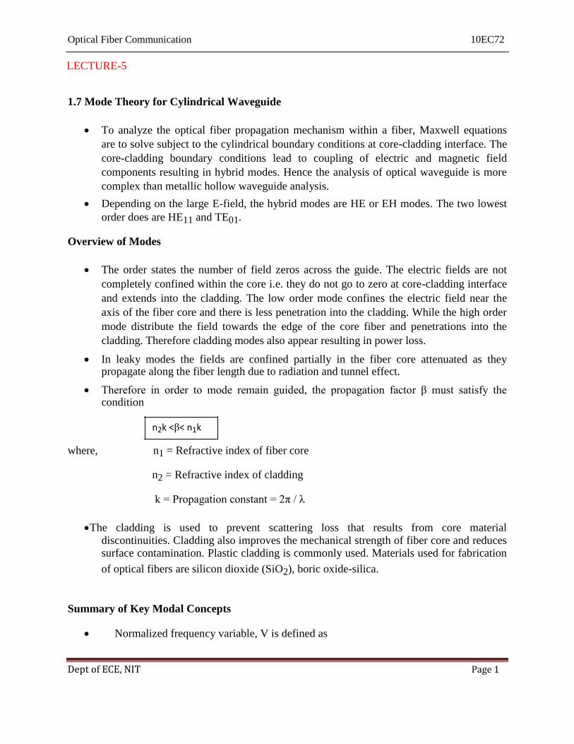
Optical Fiber Communication 10EC72 LECTURE-5 1.7 Mode Theory for Cylindrical Waveguide To analyze the optical fiber propagation mechanism within a fiber, Maxwell equations are to solve subject to the cylindrical boundary conditions at core-cladding interface. The core-cladding boundary conditions lead to coupling of electric and magnetic field components resulting in hybrid modes. Hence the analysis of optical waveguide is more complex than metallic hollow waveguide analysis. Depending on the large E-field, the hybrid modes are HE or EH modes. The two lowest order does are HE 11 and TE 01 . Overview of Modes The order states the number of field zeros across the guide. The electric fields are not completely confined within the core i.e. they do not go to zero at core-cladding interface and extends into the cladding. The low order mode confines the electric field near the axis of the fiber core and there is less penetration into the cladding. While the high order mode distribute the field towards the edge of the core fiber and penetrations into the cladding. Therefore cladding modes also appear resulting in power loss. In leaky modes the fields are confined partially in the fiber core attenuated as they propagate along the fiber length due to radiation and tunnel effect. Therefore in order to mode remain guided, the propagation factor β must satisfy the condition n 2 k <β< n 1 k where, n 1 = Refractive index of fiber core n 2 = Refractive index of cladding k = Propagation constant = 2π / λ The cladding is used to prevent scattering loss that results from core material discontinuities. Cladding also improves the mechanical strength of fiber core and reduces surface contamination. Plastic cladding is commonly used. Materials used for fabrication of optical fibers are silicon dioxide (SiO 2 ), boric oxide-silica. Summary of Key Modal Concepts Normalized frequency variable, V is defined as Dept of ECE, NIT Page 1
Transcript of 1.7 Mode Theory for Cylindrical Waveguide Overview of … · Optical Fiber Communication 10EC72...
Optical Fiber Communication 10EC72
LECTURE-5
1.7 Mode Theory for Cylindrical Waveguide
To analyze the optical fiber propagation mechanism within a fiber, Maxwell equations
are to solve subject to the cylindrical boundary conditions at core-cladding interface. The
core-cladding boundary conditions lead to coupling of electric and magnetic field
components resulting in hybrid modes. Hence the analysis of optical waveguide is more
complex than metallic hollow waveguide analysis.
Depending on the large E-field, the hybrid modes are HE or EH modes. The two lowest
order does are HE11 and TE01. Overview of Modes
The order states the number of field zeros across the guide. The electric fields are not
completely confined within the core i.e. they do not go to zero at core-cladding interface
and extends into the cladding. The low order mode confines the electric field near the
axis of the fiber core and there is less penetration into the cladding. While the high order
mode distribute the field towards the edge of the core fiber and penetrations into the
cladding. Therefore cladding modes also appear resulting in power loss.
In leaky modes the fields are confined partially in the fiber core attenuated as they propagate along the fiber length due to radiation and tunnel effect.
Therefore in order to mode remain guided, the propagation factor β must satisfy the
condition
n2k <β< n1k
where, n1 = Refractive index of fiber core
n2 = Refractive index of cladding
k = Propagation constant = 2π / λ
The cladding is used to prevent scattering loss that results from core material discontinuities. Cladding also improves the mechanical strength of fiber core and reduces surface contamination. Plastic cladding is commonly used. Materials used for fabrication
of optical fibers are silicon dioxide (SiO2), boric oxide-silica.
Summary of Key Modal Concepts
Normalized frequency variable, V is defined as Dept of ECE, NIT Page 1

Optical Fiber Communication 10EC72
… (1.7.1) where, a = Core radius
λ = Free space wavelength
Since = NA … (1.7.2)
The total number of modes in a multimode fiber is given by
‘d’ is core diameter … (17.3)
Example 1.7.1 : Calculate the number of modes of an optical fiber having diameter of 50 µm, n1= 1.48,n2
= 1.46 and λ = 0.82 µm. Solution : d = 50 µm
n1 = 1.48
n2 = 1.46
λ = 0.82 µm
NA = (1.482 – 1.46
2)1/2
NA = 0.243
Dept of ECE, NIT Page 2

Optical Fiber Communication 10EC72
Number of modes are given by,
M = 1083 …Ans.
Example 1.7.2 : A fiber has normalized frequency V = 26.6 and the operating wavelength is 1300nm. Ifthe radius of the fiber core is 25 µm. Compute the numerical aperture. Solution : V = 26.6
λ = 1300 nm = 1300 X 10-9
m
a = 25 µm = 25 X 10-6
m
NA = 0.220 … Ans. Example 1.7.3: A multimode step index fiber with a core diameter of 80 µm and a relativeindex
difference of 1.5 % is operating at a wavelength of 0.85 µm. If the core refractive index is 1.48,
estimate the normalized frequency for the fiber and number of guided modes.
[July/Aug.-2008, 6 Marks] Solution : Given : MM step index fiber, 2 a = 80 µm
Core radians a = 40 µm Dept of ECE, NIT Page 3

Optical Fiber Communication 10EC72
Relative index difference, = 1.5% = 0.015
Wavelength, λ = 0.85µm
Core refractive index, n1 = 1.48
Normalized frequency, V =?
Number of modes, M =?
Numerical aperture
= 1.48 (2 X 0.015)1/2
= 0.2563 Normalized frequency is given by,
V = 75.78 … Ans. Number of modes is given by,
…Ans.
Example 1.7.4: A step index multimode fiber with a numerical aperture of a 0.20 supportsapproximately 1000 modes at an 850 nm wavelength.
i) What is the diameter of its core?
ii) How many modes does the fiber support at 1320 nm?
iii) How many modes does the fiber support at 1550 nm? [Jan./Feb.-2007, 10 Marks]
Solution : i) Number of modes is given by,
Dept of ECE, NIT Page 4
Optical Fiber Communication 10EC72
a = 60.49 µm … Ans.
ii)
Wave Propagation Maxwell’s Equations Maxwell’s equation for non-conducting medium:
X E = - ∂B /
X H = - ∂D /
. D = 0
. B 0 Where, E and H are electric and magnetic field vectors. Dept of ECE, NIT Page 5
M = (14.39)2 = 207.07 … Ans.
iii)
… Ans.
M = 300.63 … Ans.
Optical Fiber Communication 10EC72
D and B are corresponding flux densities.
The relation between flux densities and filed vectors:
D = ε0 E + P
B = µ0 H + M Where,
ε0 is vacuum permittivity.
µ0 is vacuum permeability.
P is induced electric polarization. M is induced magnetic polarization (M = 0, for non-magnetic silica glass)
P and E are related by:
P(r, t) = ε0
Where, X is linear susceptibility.
Wave equation:
Fourier transform of E (r, t) Where, Dept of ECE, NIT Page 6
Optical Fiber Communication 10EC72
n is refractive index. α is absorption coefficient.
Both n and α are frequency dependent. The frequency dependence of n is called as chromatic dispersion or material dispersion.
For step index fiber, Fiber Modes
Optical mode: An optical mode is a specific solution of the wave equation that satisfiesboundary conditions. There are three types of fiber modes.
a) Guided modes b) Leaky modes c) Radiation modes For fiber optic communication system guided mode is sued for signal transmission.
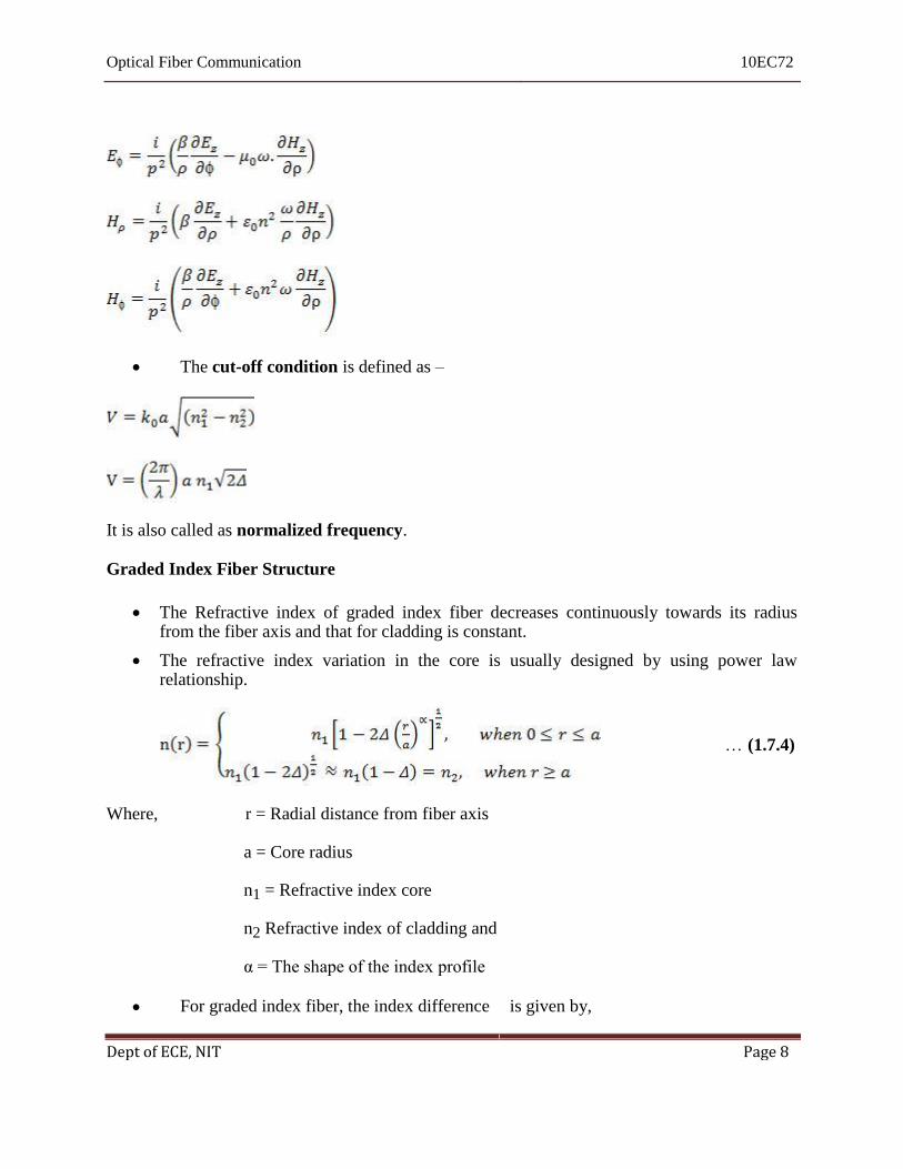
Considering a step index fiber with core radius ‘a’. The cylindrical co-ordinates ρ, and can be used to represent boundary conditions.
The refractive index ‘n’ has values
The general solutions for boundary condition of optical field under guided mode is
infinite at and decay to zero at . Using Maxwell’s equation in the core region.
Dept of ECE, NIT Page 7
Optical Fiber Communication 10EC72
The cut-off condition is defined as –
It is also called as normalized frequency. Graded Index Fiber Structure
The Refractive index of graded index fiber decreases continuously towards its radius from the fiber axis and that for cladding is constant.
The refractive index variation in the core is usually designed by using power law
relationship.
… (1.7.4) Where, r = Radial distance from fiber axis
a = Core radius
n1 = Refractive index core
n2 Refractive index of cladding and α = The shape of the index profile
For graded index fiber, the index difference is given by,
Dept of ECE, NIT Page 8

Optical Fiber Communication 10EC72
In graded index fiber the incident light will propagate when local numerical aperture at
distance r from axis, NA® is axial numerical aperture NA(0). The local numerical
aperture is given as,
The axial numerical aperture NA(0) is given as, Hence Na for graded index decreases to zero as it moves from fiber axis to core-cladding boundary.
The variation of NA for different values of α is shown in Fig. 1.7.1.
Dept of ECE, NIT Page 9

Optical Fiber Communication 10EC72
The number of modes for graded index fiber in given as,
… (1.7.6)
1.8 Single Mode Fibers
Propagation in single mode fiber is advantageous because signal dispersion due to delay
differences amongst various modes in multimode is avoided. Multimode step index fibers
cannot be used for single mode propagation due to difficulties in maintaining single mode
operation. Therefore for the transmission of single mode the fiber is designed to allow
propagation in one mode only, while all other modes are attenuated by leakage or
absorption. For single mode operation, only fundamental LP01 mode many exist. The single mode
propagation of LP01 mode in step index fibers is possible over the range.
The normalized frequency for the fiber can be adjusted within the range by reducing core
radius and refractive index difference < 1%. In order to obtain single mode operation
with maximum V number (2.4), the single mode fiber must have smaller core diameter
than the equivalent multimode step index fiber. But smaller core diameter has problem of
launching light into the fiber, jointing fibers and reduced relative index difference.
Graded index fibers can also be sued for single mode operation with some special fiber
design. The cut-off value of normalized frequency Vc in single mode operation for a
graded index fiber is given by,
Example 1.8.1: A multimode step index optical fiber with relative refractive index
difference1.5% and core refractive index 1.48 is to be used for single mode operation. If the
operating wavelength is 0.85µm calculate the maximum core diameter. Solution: Given
n1 = 1.48
∆ = 1.5 % = 0.015 Dept of ECE, NIT Page 10
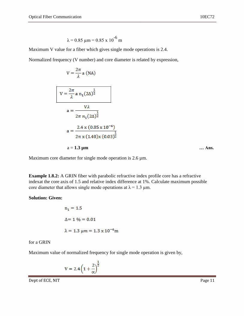
Optical Fiber Communication 10EC72
λ = 0.85 µm = 0.85 x 10⁻⁶
m Maximum V value for a fiber which gives single mode operations is 2.4. Normalized frequency (V number) and core diameter is related by expression,
a = 1.3 µm … Ans. Maximum core diameter for single mode operation is 2.6 µm. Example 1.8.2: A GRIN fiber with parabolic refractive index profile core has a refractive
indexat the core axis of 1.5 and relative index difference at 1%. Calculate maximum possible
core diameter that allows single mode operations at λ = 1.3 µm. Solution: Given:
for a GRIN Maximum value of normalized frequency for single mode operation is given by,
Dept of ECE, NIT Page 11

Optical Fiber Communication 10EC72
Maximum core radius is given by expression,
a = 3.3 µm … Ans.
Maximum core diameter which allows single mode operation is 6.6 µm.
Dept of ECE, NIT Page 12