17-43GHz, 0.1W Gain Block - Microwave TechnologyThe MMA-174321 is a broadband GaAs MMIC general...
7
MMA-174321 17-43GHz, 0.1W Gain Block MicroWave Technology, Inc., 4268 Solar Way, Fremont, CA 94538 510-651-6700 FAX 510-952-4000 WEB www.mwtinc.com Subject to change without notice. All rights reserved © ECCN: 3A001.b.2.d Please visit MwT website www.mwtinc.com for information on other MwT MMIC products. Page 1 of 7, Updated July 2017 Features: • Frequency Range: 17 – 43 GHz • P1dB: 21 dBm • Psat: 22 dBm • Gain: 22 dB • Vdd =5 V (3 V to 5 V) • Ids = 200 mA (150mA to 300mA) • Input and Output Fully Matched to 50 Ω • 2x and 3x Frequency multiplier applications Applications: • Communication systems • Microwave instrumentations Description: The MMA-174321 is a broadband GaAs MMIC general purpose gain block for 0.1-Watt maximum output power and high gain over full 17 to 43GHz frequency range. This amplifier is able to use as 2x and 3x Frequency multipliers when biased under class-B condition for the first stage. Electrical Specifications: Vds=5V,Vgs=-0.7V, Ids=200mA, Ta=25 °C Z0=50 ohm Parameter Units Typical Data Frequency Range GHz 17-43 Gain (Typ / Min) dB 22 / 20 Gain Flatness (Typ / Max) +/-dB 2.0 / 2.5 Input RL(Typ/Max) dB 8/6 Output RL(Typ/Max) dB 8/6 Output P1dB(Typ/Min) dBm 21/19.5 Output IP3 (1) dBm 26 Output Psat(Typ/Min) dBm 22/20.5 Operating Current at P1dB (Typ/Max) mA 240 / 250 Thermal Resistance °C /W 30 (1) Output IP3 is measured with two tones at output power of 5 dBm/tone separated by 20 MHz. Die size: 1720 x 760 x 50 um 69 x 30 x 2 mil
Transcript of 17-43GHz, 0.1W Gain Block - Microwave TechnologyThe MMA-174321 is a broadband GaAs MMIC general...

MMA-174321 17-43GHz, 0.1W Gain Block
MicroWave Technology, Inc., 4268 Solar Way, Fremont, CA 94538 510-651-6700 FAX 510-952-4000 WEB www.mwtinc.com
Subject to change without notice. All rights reserved © ECCN: 3A001.b.2.dPlease visit MwT website www.mwtinc.com for information on other MwT MMIC products.
Page 1 of 7, Updated July 2017
Features: • Frequency Range: 17 – 43 GHz• P1dB: 21 dBm• Psat: 22 dBm• Gain: 22 dB• Vdd =5 V (3 V to 5 V)• Ids = 200 mA (150mA to 300mA)• Input and Output Fully Matched to 50 Ω• 2x and 3x Frequency multiplier applications
Applications: • Communication systems• Microwave instrumentations
Description: The MMA-174321 is a broadband GaAs MMIC general purpose gain block for 0.1-Watt maximum output power and high gain over full 17 to 43GHz frequency range. This amplifier is able to use as 2x and 3x Frequency multipliers when biased under class-B condition for the first stage.
Electrical Specifications: Vds=5V,Vgs=-0.7V, Ids=200mA, Ta=25 °C Z0=50 ohm
Parameter Units Typical Data
Frequency Range GHz 17-43Gain (Typ / Min) dB 22 / 20Gain Flatness (Typ / Max) +/-dB 2.0 / 2.5Input RL(Typ/Max) dB 8/6Output RL(Typ/Max) dB 8/6 Output P1dB(Typ/Min) dBm 21/19.5Output IP3 (1) dBm 26 Output Psat(Typ/Min) dBm 22/20.5Operating Current at P1dB (Typ/Max)
mA 240 / 250
Thermal Resistance °C /W 30(1) Output IP3 is measured with two tones at output power of 5 dBm/tone separated by 20 MHz.
Total Size: 1720 x 760Scribe Alley: 70 x 70
Die size: 1720 x 760 x 50 um 69 x 30 x 2 mil

MMA-174321
Typical RF Performance: Vds=5V, Vgs=-0.7V, Ids=200mA, Z0=50 ohm, Ta=25 ºC
10 15 20 25 30 35 40 45 50Frequency (GHz)
-20
-15
-10
-5
0
5
10
15
20
25
30
35
S11,
S21
, and
S22
(dB
)
DB(|S(1,1)|)MEAS
DB(|S(2,1)|)MEAS
DB(|S(2,2)|)MEAS
10 15 20 25 30 35 40 45 50Frequency (GHz)
0
10
20
30
40
50
K-fa
ctor
31.62 GHz3.352
K()MEAS
S11[dB], S21[dB], and S22[dB] vs. Frequency
P-1 and Psat vs. Frequency
K-factor vs. Frequency
IM3 level [dBc] vs. Input power [dBm/tone]
MicroWave Technology, Inc., 4268 Solar Way, Fremont, CA 94538 510-651-6700 FAX 510-952-4000 WEB www.mwtinc.com
Subject to change without notice. All rights reserved © Please visit MwT website www.mwtinc.com for information on other MwT MMIC products.
Page 2 of 7, Updated July 2017

MMA-174321 17-43GHz, 0.1W Gain Block
Frequency 2x and 3x multiplier Data:
Measured 2x multiplier data: Pin=9dBm, Vd1=5V, Vd2=5V, Vg1=-1.4V, Vg2=-0.7V, Id1=1mA, and Id2=163mA
Measured 3x multiplier data: Pin=9dBm, Vd1=1V, Vd2=5V, Vg1=-0.75V, Vg2=-0.75V, Id1=21mA, and Id2=144mA
MicroWave Technology, Inc., 4268 Solar Way, Fremont, CA 94538 510-651-6700 FAX 510-952-4000 WEB www.mwtinc.com
Subject to change without notice. All rights reserved © Please visit MwT website www.mwtinc.com for information on other MwT MMIC products.
Page 3 of 7, Updated July 2017

MMA-174321 17-43GHz, 0.1W Gain Block
ApplicationsThe MMA-174321 MMIC general purpose amplifier is designed for use as a gain stage amplifier in microwave transmitters. It is ideally suited for 17 to 43GHz band applications requiring a flat gain response and excellent power performance. This amplifier is provided as a bare die format in a Gel-pak.
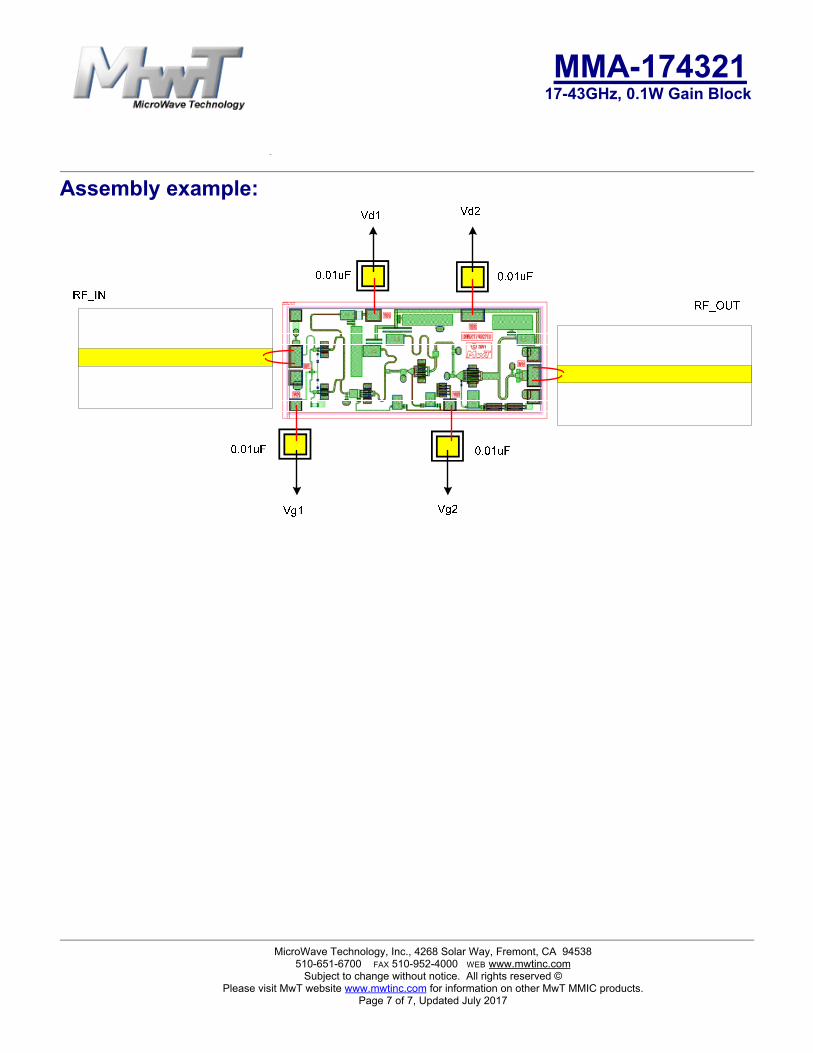
Biasing and Operation The recommended bias conditions for best performance for the MMA-174321 are VDD = 5.0V, Idsq = 200mA. Performance improvements are possible depending on applications. The drain bias voltage range is 3 to 6V and the quiescent drain current biasing range is 150mA to 250mA. Vg1 is connected to first stages of gate, and Vg2 is connected to following three stages of gates. Muting can be accomplished by setting Vg1 and Vg2 to the pinched-off voltage (Vp=-2V). The gate voltages (Vg1 and Vg2) should be applied prior to the drain voltages (Vd1 and Vd2) during power up and removed after the drain voltages during power down. The RF input port is connected internally to the 50Ω load for ESD protection purpose; therefore, an input decoupling capacitor is needed if the preceding output stage has DC present. The RF output is DC decoupled internally. Typical DC supply connection with bi-passing capacitors for the MMA-174321 is shown in following pages.
Frequency x2 and x3 Multiplier Applications: MMA-174321 is able to use as a frequency x2 multiplier when biased under Vd1=5V, Vd2=5V, Vg1=-1.4V, Vg2=- 0.7V, Id1=1mA, and Id2=163mA. Optimum input RF power level is +9dBm. Typical measured data is shown in previous page. MMA-174321 is also able to use as a frequency x3 multiplier when biased under Vd1=1V, Vd2=5V, Vg1=-0.75V, Vg2=-0.75V, Id1=21mA, and Id2=144mA. Optimum input RF power level is +9dBm. Typical measured data is shown in previous page.
Assembly Techniques GaAs MMICs are ESD sensitive. ESD preventive measures must be employed in all aspects of storage, handling, and assembly. MMIC ESD precautions, handling considerations, die attach and bonding methods are critical factors in successful GaAs MMIC performance and reliability.
MicroWave Technology, Inc., 4268 Solar Way, Fremont, CA 94538 510-651-6700 FAX 510-952-4000 WEB www.mwtinc.com
Subject to change without notice. All rights reserved ©Please visit MwT website www.mwtinc.com for information on other MwT MMIC products.
Page 4 of 7, Updated July 2017

MMA-174321 17-43GHz, 0.1W Gain Block
Mechanical Information: Top view
To ta l Si z e : 1 7 2 0 x 7 6 0Sc rib e Al le y : 7 0 x 7 0
Vd10
GND
RF_IN
85 600
400
760
Vd2
RF_OUT0 0
Vg1
0 85 17201100Vg2
1250
760
1720
280
Units are in um.
MicroWave Technology, Inc., 4268 Solar Way, Fremont, CA 94538 510-651-6700 FAX 510-952-4000 WEB www.mwtinc.com
Subject to change without notice. All rights reserved © Please visit MwT website www.mwtinc.com for information on other MwT MMIC products.
Page 5 of 7, Updated July 2017

MMA-174321 17-43GHz, 0.1W Gain Block
Application Circuit:
MicroWave Technology, Inc., 4268 Solar Way, Fremont, CA 94538 510-651-6700 FAX 510-952-4000 WEB www.mwtinc.com
Subject to change without notice. All rights reserved © Please visit MwT website www.mwtinc.com for information on other MwT MMIC products.
Page 6 of 7, Updated July 2017
MMA-174321 17-43GHz, 0.1W Gain Block
Assembly example:
MicroWave Technology, Inc., 4268 Solar Way, Fremont, CA 94538 510-651-6700 FAX 510-952-4000 WEB www.mwtinc.com
Subject to change without notice. All rights reserved © Please visit MwT website www.mwtinc.com for information on other MwT MMIC products.
Page 7 of 7, Updated July 2017