
16.810 L11 Sobieski Optimization - MIT OpenCourseWare · 2017-12-28 · as functions of a design...
61
Issues in Optimization Jaroslaw Sobieski NASA Langley Research Center Hampton Virginia NASA Langley Research Center Hampton, VA 23681; MS240 LaRC/SMC/ACMB Copyright NASA, Jaroslaw Sobieski, 2003
Transcript of 16.810 L11 Sobieski Optimization - MIT OpenCourseWare · 2017-12-28 · as functions of a design...

Issues in Optimization
Jaroslaw SobieskiNASA Langley Research Center
Hampton Virginia
NASA Langley Research Center Hampton, VA 23681; MS240
LaRC/SMC/ACMB Copyright NASA, Jaroslaw Sobieski, 2003

How to know whether optimization is needed

How to recognize thatthe problem at hand needs
optimization.• General Rule of the Thumb: there must be at least two opposing trends as functions of a design variable
Analysis
x f1 f1
f2
f2
f1 f2 x

Power Line Cabletout cable
slack cable h
Length(h) A(h) Volume(h) A
L
V
min • Given:
• Ice load • self-weight small • h/span small
tout h slack

Wing Thin-Walled BoxLift
•Top cover panels are compressed
b
thickness t
•Buckling stress = f(t/b)2
b fewmany
Cover weight
Rib total weight
Wing box weight
min
ribs ribs
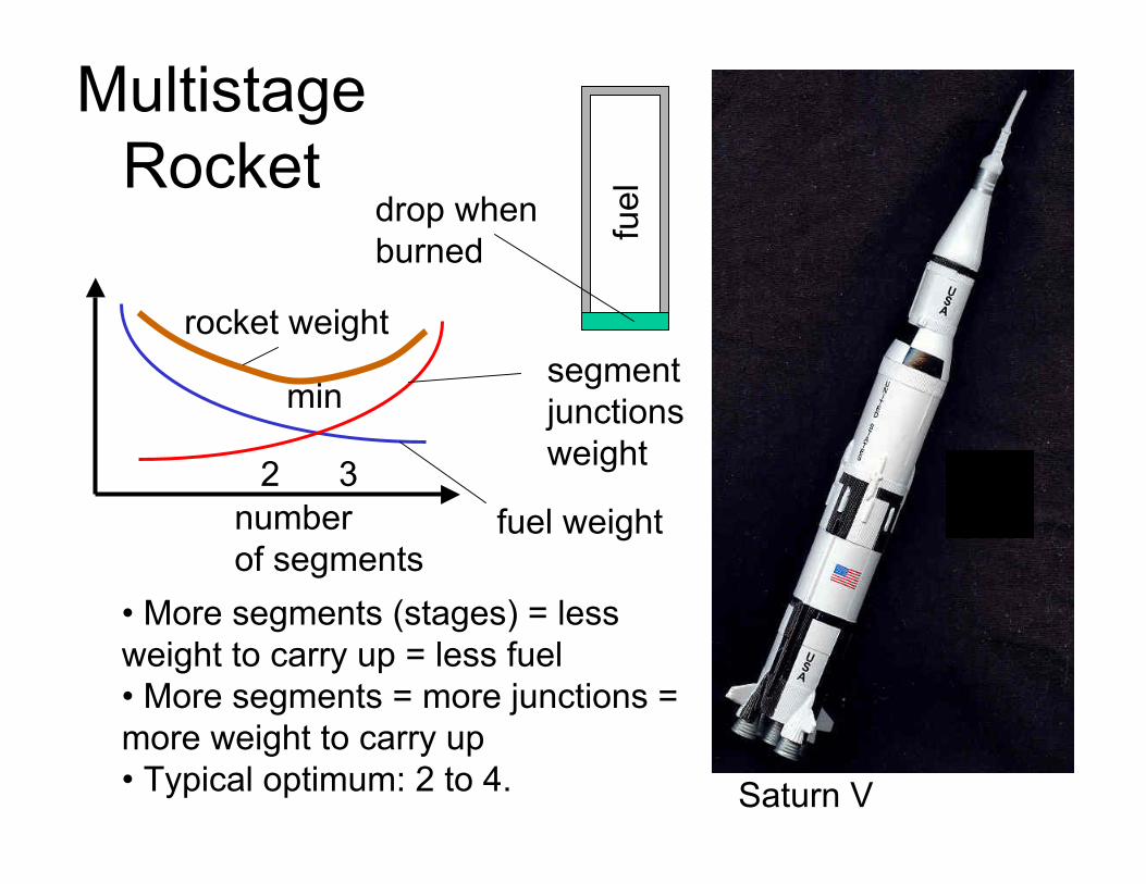
Multistage Rocket
fueldrop when
burned
number of segments
fuel weight
segment junctions weight
rocket weight
2 3
min
weight to carry up = less fuel
more weight to carry up
• More segments (stages) = less
• More segments = more junctions =
• Typical optimum: 2 to 4. Saturn V

Under-wing Nacelle Placement
longer body to rotate for take-off =more weight fore nacelle aft
shock wave
drag
nacelle
wing underside
shock wave impinges on forward slope = drag
moves with it = larger tail (or drag
weight Range
max• Inlet ahead of wing max. depth =
• Nacelle moved aft = landing gear

National Taxation
tax paid on $ earned
revenue collected
max
incentive to work 0 % average 100 %
tax rate
• More tax/last $ = less reason to strive to earn • More tax/$ = more $ collected per “unit of economic activity”

National Taxation
revenue collected
max tax paid on $ earned
incentive to work 0 % average 100 %
tax rate • More tax/last $ = less reason to strive to earn • More tax/$ = more $ collected per “unit of economic activity”• What to do:
• If we are left of max = increase taxes • If we are right of max = cut taxes

Nothing to Optimize
Rod P Newton
A cm2
• Monotonic trend • No counter-trend σ σ allowable • Nothing to optimize N/cm2
A

Various types of design optima

Design Definition: Sharp vs. constraints - 0 contours Shallow
- bad side of
1
2 12
bandpoint
constraints - 0 contours
X X
Objective
Constraint descent
• Near-orthogonal intersection defines a design point
• Tangential definition identifies a band of of designs
X

Multiobjective Optimizationtrade-both Q = 1/(quality &
f1 off both
performance &f2 comfort)
$ 1
4 $ 4 pareto-frontier
233 2
design & manufacturingsophistication
1
Q pareto-optimum
V&W R&R

A Few Pareto-Optimization Techniques
• Reduce to a single objective: F = Σi wi fi where w’s are judgmental weighting factors
• Optimize for f1; Get f*1;; •Set a floor f1 >= f*i ; Optimize for f2; get f2 ; • Keep floor f1, add floor f2 ; Optimize for f3 ; • Repeat in this pattern to exhaust all f’s;
• The order of f’s matters and is judgmental
• Optimize for each f independently; Get n optimal designs;i Find a compromise design equidistant from all the above.
• Pareto-optimization intrinsically depends on judgmental preferences

Imparting Attributes by Optimization
• Changing wi in F = Σi wi fi modifies the design within broad range
• Example: Two objectives • setting w1 = 1; w2 = 0 produces design whose F = f1 • setting w1 = 0; w2 = 1 produces design whose F = f2 • setting w1 = 0.5; w2 = 0.5 produces design whose
F is in between.
• Using w as control, optimization serves as a tooli to “steer” the design toward a desired behavior orhaving pre-determined, desired attributes.

Optimum: Global vs. LocalX2
Why the problem: Objective contours•Nonconvex
objective orconstraintconstraints
(wiggly contours) X1
L
G
resonance
d Spring k N/cm •Disjoint design mass space
d P
P = p cos (ωt) k
• Local information, e.g., derivatives, does not distinguish local from global optima - the Grand Unsolved Problem in Analysis

• Use a multiprocessor computer• Start from many initial designs• Execute multipath optimization
• Increase probability of locatingglobal minimum
• Probability, no certainty• Multiprocessor computing =analyze many in time of one = new situation = can do what could not be done before.
What to do about itA “shotgun” approach:
F
Start
M1
Opt.
Tunnel
M2<M1
X
•“Tunneling” algorithmfinds a better minimum

A “shotgun” approach:
• Use a multiprocessor computer• Start from many initial designs• Execute multipath optimization
• Increase probability of locatingglobal minimum
• Probability, no certainty• Multiprocessor computing =analyze many in time of one = new situation = can do what could not be done before.
What to do about it
F
Start
M1
Opt.
Tunnel shotgun Multiprocessor computer
M2<M1
X
•“Tunneling” algorithmfinds a better minimum

What to do about itA “shotgun” approach:
X
F
Start
M1 M2<M1
Tunnel
Opt.
•“Tunneling” algorithmfinds a better minimum
• Use a multiprocessor computer• Start from many initial designs• Execute multipath optimization
• Increase probability of locating global minimum
• Probability, no certainty • Multiprocessor computing =analyze many in time of one = new situation = can do what could not be done before.

Using Optimization to Impart Desired Attributes

Larger scale example: EDOF = 11400; Des. Var. = 126; Constraints = 24048;Built-up, trapezoidal, slender transport aircraft wing• Design variables: thicknesses of sheet metal, rod cross-sectional areas, inner volume (constant span and chord/depth ratio
• Constraints: equivalent stress and tip displacement
•Two loading cases: horizontal, 1 g flightwith engine weight relief, and landing.
npas
ft70
• Four attributes: • structural mass • 1st bending frequency • tip rotation • internal volume

Case : F = w1 (M/M0) + w2 (Rotat/Rotat0)
Normalized Mass M/M0
•Broad variation: 52 % to 180 %
Rotation weight factor Mass
weight factor
Rotat = wingtip twist angle

Optimization Crossing the Traditional Walls of Separation

Optimization AcrossConventional Barriers
data Vehicle design Fabrication
• Focus on vehicle physics • Focus on manufacturing and variables directly
related to it process and its variables • E.g, range; • E.g., cost; wing aspect ratio riveting head speed

Two Loosely Connected Optimizations
•Seek design variables • Seek process variables to maximize performance to reduce the fabrication cost. under constraints of:
Physics Cost Manufacturing difficulty
The return on investment (ROI) is a unifying factor ROI = f(Performance, Cost of Fabrication)

Integrated Optimization
• Required: Sensitivity analysis on both sides
∂Range/ ∂(AspectRatio) ∂Cost/ ∂(Rivet head speed)
∂(Rivet head speed)/ ∂(AspectRatio)
ROI = f(Range, Cost of Fabrication) ∂ROI/ ∂AspectRatio = ∂ROI/ ∂Cost ∂Cost/ ∂(Rivet h.s.) ∂(Rivet h.s)/ ∂(AspectRatio) +
+ ∂(ROI)/∂Range ∂Range/∂(AspectRatio)

Integrated Optimization Design < --- > Fabrication
• Given the derivatives on both sides
Design Fabrication
• Unified optimization may be constructed to seek vehicle design variable, e.g., AspectRatio, for maximum ROI incorporating AR effect on Range and on
AR Opt.
fabrication cost. ROI ROI Range
Cost
Range; Cost

Optimization Applied to Complex Multidisciplinary Systems
Multidisciplinary Optimization MDO

Coupling
Decomposition
What to optimize for at the discipline level
Approximations
Sensitivity

Wing drag and weight both influence the flight range R.R is the system objective
P P Loads
Displacements
a = sweep angle a
• directly by weight • indirectly by stiffness that affect displacements that affect drag
Loads & Displacements must be consistent
Wing - structure Wing - aerodynamics
• Structure influences R by
R = (k/Drag) LOG [( Wo + Ws + Wf)/ (Wo + Ws )]
• Dilemma: What to optimize the structure for? Lightness? Displacements = 1/Stiffness? An optimal mix of the two?

Trade-off between opposing objectivesof lightness and stiffness
Weight Displacement Weight
Displacement ~ 1/Stiffness
Thickness limited by stress
Wing cover sheet thickness
Lightness Stiffness
• What to optimize for? • Answer: minimum of f = w1 Weight + w2 Displacement • vary w1, w2 to generate a population of wings of diverse Weight/Displacement ratios • Let system choose w1, w2.

Approximations
•Why Approximations: Analyzer Optimizer
Optimizer
Analyzer
Approximate Model
Human judgment
problems
• Now-standard practice for large problems to reduce and control cost
$$
cents
• a.k.a. Surrogate Models
• OK for small

Design of Experiments(DOE) & Response Surfaces (RS)
• RS provides a “domain guidance”, rather than local guidance, to system optimizer
DOE
•Placing design points indesign space in a pattern
•Example: Star pattern (shown incomplete)
RS
X1
X2
F(X)
F(X) = a + {b}’{X} + {X}’[c]X •quadratic polynomial •hundreds of variables

Response Surface Approximation
• A Response Surface is an n-dimensional hypersurface relating n
• Design of Experiments (DOE) methods used to disperse data points in design space.
• More detail on RS in section on Approximations
inputs to a single response (output).
Res
pons
e
Variable 1 Variable 2

BLISS 2000: MDO Massive Computational Problem Solved by RS (or alternative approximations)
Optimization of subsystem or discipline
or discipline
Optimization of subsystem or discipline
System optimization
X1 X2
F(X)
X1 X2
F(X)
X1
X2
F(X)
RS
RS
Precompute off-line in parallel
Instantaneousresponse
MC
DATA
BASE
Analysis of subsystem cloud
• Radical conceptual simplification at the price of a lot more computing. Concurrent processing exploited.

Coupled System Sensitivity • Consider a multidisciplinary YAsystem with two subsystems
A and B (e.g. Aero. & Struct.) – system equations can be
written in symbolic form as[( , B ),Y Y X A A ] = 0A
[( , A ),Y Y X B B ] = 0B
– rewrite these as follows YA = Y X Y B )A ( A ,YB = Y X Y A )B ( B ,
A
B
AX
BX
BY
BYAY
these governing equations define
as implicit functions. Implicit Function Theorem applies.

Coupled System Sensitivity Equations
• These equations can be represented in matrix notation as Y dY∂⎡ ⎧⎤ ⎫A AI − Y A∂⎧ ⎫
⎪⎬
⎢⎢⎢⎢⎣
⎥⎥⎥⎥⎦
⎪⎪⎨⎪⎪⎩
Y dX∂ ⎪⎪⎬ ∂
⎪⎨=B A XY dY
dX
∂ A⎪⎩⎪
⎪⎭ ⎪⎭
B B
A
I− 0Y∂ differentA
same Y dY
dX
∂⎡ ⎧⎤ ⎫ Right Hand SidesA A
B
I − 0=
⎧⎪⎨
⎫⎪⎬
matrix ⎢⎢⎢⎢⎣
⎥⎥⎥⎥⎦
⎪⎪⎨⎪⎪⎩
Y∂ ⎪⎪⎬ Y∂B BY dY
dX
∂ ⎪⎩⎪⎪⎭
⎪⎭B B
B
X∂I− BY∂ A
• Total derivatives can be computed if partial sensitivities computed in each subsystem are known
Linear, algebraical equations with multiple RHS

Example of System Derivativefor Elastic Wing
• Example of partial and system sensitivities
Ang
le o
f atta
ckde
g
10
Based on rigid wing – partial derivative 7.0
Based on elastic wing – system derivative 4.0
-40 -30 -20 -10 0
¼ chord sweep angle -deg
• In this example, the system coupling reverses the derivative sign

X
Flowchart of the System Optimization Process
System Analysis α β
γ
System Sensitivity Analysis α β γ
Sensitivity solution
Optimizer
Start
Approximate Analysis
X Yγ Yα
β
Yβ
Stop

Cou
p li n
g B
read
th
System Internal Couplings Quantified
All-in-One
Decompose
((Decompose))
(Decompose)
• Strength: relatively large ∂ YO/ ∂YI
• Breadth: {YO} and {YI} are long
[∂ YO/ ∂YI] large and full
Coupling Strength

A Few Recent Application Examples
Multiprocessor Computers create a new situation for MDO

Supersonic Business Jet Test Case
• Structures (ELAPS)
• Aerodynamics (lift, drag, trim supersonic wave drag by A - Wave)
• Propulsion (look-up tables)
• Performance (Breguet equation for Range)
Examples: Xsh - wing aspect ratio, Engine scale factor Xloc - wing cover thickness, throttle setting Y - aerodynamic loads, wing deformation.
Some stats:
Xlocal: struct. 18aero 3propuls. 1
X shared: 9Y coupl.: 9

System of Modules (Black Boxes) for Supersonic Business Jet Test Case
Aero
Struct.
Propulsion
Perform.
• Data Dependence Graph • RS - quadratic polynomials, adjusted for error control

0
1
1 10
Flight Range as the ObjectiveN
orm
aliz
ed
Cycles
0.2
0.4
0.6
0.8
1.2
1.4
2 3 4 5 6 7 8 9
Series1
Series2
RS Analysis
1
101 0
• Histogram of RS predictions and actual analysis for Range

12
Air Borne Laser System Design:another application of the similar scheme
Beam Control SystemBeam Control System System Level DesignSystem Level Design• Turret Assembly • Boeing
•Large Optics • CDR 25-27 April •Four Axis gimbals •Transfer optics 747F Aircraft747F Aircraft -
• Beam Transfer Assembly •• BoeingBoeing•Sensor Suite •Active Mirrors • CDR 29 Feb - 3 Mar •Illuminators •Electronics •Software/Processors
BMCBMC44II
Chemical Oxygen IodineChemical Oxygen IodineLaser (COIL)Laser (COIL) • TRW • 21-23 March
• Boeing • 8-10 March

A Candidate for Shuttle Replacement: Two-stage Orbital Transport
• Collaborated with GWU, and ASCAC Branches: System Analysis and Vehicle Analysis
2nd stage separates and continues
500000 LB x UB
900000
810000
720000
630000
450000
360000
270000
180000
90000
0
RS True
• Result sample: System Weight (lb)Variance over MDO iterations. booster
Fly-back
• Initial design was infeasible
to destination

NVH Model• A Body-In-Prime (BIP) Model - Trimmed Body Structure
without the powertrain and suspension subsystems
• MSC/NASTRAN Finite Element Model of 350,000+ edof;
• Normal Modes, Static Stress, & Design Sensitivity analysis using Solution Sequence 200;
• 29 design variables (sizing, spring stiffness);

Computational Performance • Fine grain parallelism of Crash Code was an important factor
in reducing the optimization procedure total elapsed time:291 hours cut to 24 hours for a single analysis using 12 processors.
• Response Surface Approximation for crash responses that enabled coarse grain parallel computing provided significant reduction in total elapsed time: 21 concurrent crash analysis using 12 processors each over 24 hours (252 processors total).
• For effective utilization of a multiprocessor computer, userhas to become acquainted with the machine architecture.
255 days of elapsed computing time cut to 1 day

Computer Power vs. Mental Power
Quantity vs Quality

Invention by Optimization?P
A I
b P
{X} = {A, I, b}; Minimize weight; See b Zero• Optimization transformed frame into truss •A qualitative change•Why:
•structural efficiency is ranked:Tension best
Compression Bending worst
• If one did not know this, and would not know the concept ofa truss, this transformation would look as invention of truss.

Optimizing Minimum Drag/Constant Lift Airfoilfor Transonic Regime
Base
New
(he use a file & wind tunnel), this would look like an invention. • If this was done before Whitcomb invented the flat-top airfoil
• Drag minimized while holding constant lift by geometrically adding the base airfoils. • Each base airfoil had some aerodynamic merit • Result: a new type, flat-top “Whitcomb airfoil”.

Continuous quantitative transformation vs. conceptual quantum jump
•Common feature in both previous examples:
•Variable(s) existed whose continuous changeenabled transformation to qualitatively new design
X no seed
• Counter-example:
for 2nd wing
OK Second wing may
wither away
• Optimization may reduce but cannot grow what is not there, at least implicitly, in the initial design.

Technology Progress: Sigmoidal Staircase
piston/jet vacuum tube/transistor film/digital camera“P
erfo
rman
ce”
Time exhaustion
inception
rapid advance; optimization
• Optimization assists in rapid advance phase • Human creativity “shifts gears” to next step

Augmenting number crunching powerof computer with “good practice” rules

Topology Optimization• Modern version of what Michelangelo said 500 years ago:(paraphrased)“to create a sculpture just remove the unnecessary material”
Basematerial
membersIn compression•This optimization cannot include buckling
constraints because the slender members are not defined until the end.
• Subtle point: it is difficult to keep the analysis valid when the imparted change calls for new constraints.
Topology optimization removes “pixels” from base material

Topology Optimization - 2
Base material
theoretical as built
members •This optimization can not include buckling In compression constraints because the slender members do not emerge as such until the end.
• Subtle point: it is difficult to keep the analysis valid when the imparted change requires new constraints.
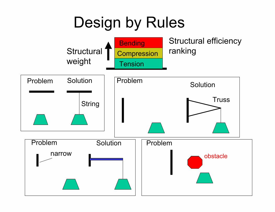
Design by Rules
Compression Bending
Tension
Structural efficiencyrankingStructural
weight
Problem Solution
String
Problem Solution
Truss
Problem Solution narrow
Problem
obstacle

Complications…
Solution 1 Solution 2
….things are getting too complicated
• Human eye-brain apparatus excels in handling geometrical complexities amplified by abundance of choices
• By some evidence, eye-brain apparatus may process 250 MB data in a fraction of a second.

Optimization in Design Processfeedback
Need or Opportunity
Concept Preliminary Design
Detailed Design
Prototype Production
Qualitative Quantitative
Firm foothold
research extension trend
• Optimization most useful where quantitative content is high

Closure
• Optimization became an engineer’s partner in design
• It excels at handling the quantitative side of design
• It’s applications range from component to systems
• It’s utility is dramatically increasing with the advent of massively concurrent computing
• Current trend: extend optimization to entire life cyclewith emphasis on economics, include uncertainties.
• Engineer remains the principal creator, data interpreter, and design decision maker.
LaRC/SMC/ACMB Copyright NASA, Jaroslaw Sobieski, 2003

Dr. Jaroslaw Sobieski Degrees through doctorate in technical sciences from the Technical University of Warsaw (TUW), Poland. Concurrently with industry design and consulting, faculty positions at TUW 1955-66, St. Louis University 1966-71; George Washington University 197291; University of Virginia 1991- present; and post-doctoral research at the Technical University of Norway, Trondheim, 196465 and summer 1966. On the staff of NASA Langley since 1971, several research and supervisory position in structural and in multidisciplinary analysis & design optimization, and design studies of aerospace systems. Manager of the Langley's portion of the Computational Aerospace Sciences Project under the High Performance Computing and Communication Program HPCCP, 1996-2000. Currently Sr. Res. Scientist in Analytical and Computational Methods. AIAA Fellow and the Founding Chairman of the AIAA Technical Committee for Multidisciplinary Design Optimization. Recipient of: the NASA Medal for Exceptional Engineering Achievement, and the AIAA National Award for Multidisciplinary Analysis and Optimization in 1996. Co-Recipient of the SAE Wright Brothers Medal 1999. Several technical publications in professional journals and books. Co-Editor of international journal Structural and Multidisciplinary Optimization. Listed in the Marquis' Who is Who in America and Who is Who in the World.


