
1636 JOURNAL OF LIGHTWAVE TECHNOLOGY, VOL. 31,...
9
1636 JOURNAL OF LIGHTWAVE TECHNOLOGY, VOL. 31, NO. 10, MAY 15, 2013 Tunable Microwave and Sub-Terahertz Generation Based on Frequency Quadrupling Using a Single Polarization Modulator Weilin Liu, Student Member, IEEE, Muguang Wang, Member, IEEE, and Jianping Yao, Fellow, IEEE, OSA Abstract—Frequency quadrupling for tunable microwave and sub-terahertz generation using a single polarization modulator (PolM) in a Sagnac loop without using an optical filter or a wideband microwave phase shifter is proposed and experimen- tally demonstrated. In the proposed system, a linearly polarized continuous wave from a tunable laser source (TLS) is split into two orthogonally polarized optical waves by a polarization beam splitter (PBS) and sent to the Sagnac loop traveling along the clockwise and counter-clockwise directions. A PolM to which a reference microwave signal is applied is incorporated in the loop. The PolM is a traveling-wave modulator, due to the velocity mismatch only the clockwise light wave is effectively modulated by the reference microwave signal, and the counter-clockwise light wave is not modulated. This is the key point that ensures the can- celation of the optical carrier without the need of an optical filter. Along the clockwise direction, the joint operation of the PolM, a polarization controller (PC), and a polarizer corresponds to a Mach–Zehnder modulator (MZM) with the bias point controlled to suppress the odd-order sidebands. The optical carrier is then suppressed by the counter-clockwise light wave at the polarizer. As a result, only two nd-order sidebands are generated, which are applied to a photodetector (PD) to generate a microwave signal with a frequency that is four times that of the reference microwave signal. A theoretical analysis is developed, which is validated by an experiment. A frequency-quadrupled electrical signal with a large tunable range from 2.04 to 100 GHz is generated. The performance of the proposed system in terms of stability and phase noise is also evaluated. Index Terms—Carrier suppression, microwave photonics, mi- crowave technology, optical interference, polarization modulation, photonic generation of microwave signals. I. INTRODUCTION M ICROWAVE generation in the optical domain has been a topic of interest, and numerous approaches have been proposed in the last few years [1]. The key advantages of gen- erating microwave signals by photonic means are the low phase Manuscript received December 02, 2012; revised February 23, 2013; accepted March 20, 2013. Date of publication March 26, 2013; date of current version April 15, 2013. This work was supported in part by the Natural Science and Engineering Research Council of Canada (NSERC). W. Liu and J. Yao are with the Microwave Photonics Research Laboratory, School of Electrical Engineering and Computer Science, University of Ottawa, ON K1N 6N5, Canada (e-mail: [email protected]). M. Wang is with the Institute of Lightwave Technology, Key Lab of All Optical Network and Advanced Telecommunication Network of EMC, Bei- jing Jiaotong University, Beijing 100044, China, and also with the Microwave Photonics Research Laboratory, School of Electrical Engineering and Computer Science, University of Ottawa, Ottawa, ON K1N 6N5, Canada. Color versions of one or more of the figures in this paper are available online at http://ieeexplore.ieee.org. Digital Object Identifier 10.1109/JLT.2013.2254699 noise, high frequency, and wide frequency tunability. In addi- tion, photonic generation of microwave signals is inherently compatible with radio-over-fiber (RoF) systems, which offer several advantages over radio-over-coaxial systems, namely, wide bandwidth, low loss, and immunity to electromagnetic in- terference (EMI). To generate a microwave signal in the optical domain, optical heterodyning has been widely used [1]–[15], in which two optical waves of different wavelengths beat at a photodetector (PD). A microwave signal with a frequency cor- responding to the wavelength spacing of the two optical waves is then generated at the output of the PD. The critical factor here is to produce two phase-correlated optical waves to ensure a low phase noise of the generated microwave. To obtain two phase-correlated wavelengths, the following techniques have been among those proposed: optical injection locking (OIL) [2], [3]; optical mode locking [4], [5]; optical phase-locked loop (OPLL) [6], [7]; using a dual-wavelength laser source [8]–[10]; and external modulation [11]–[19]. Among these techniques, external modulation has been considered an attrac- tive solution due to its simplicity and stability, in addition to the large frequency tunability, and high spectral purity of the generated microwave signal [11]. In 1992, O’Reilly et al. first proposed and demonstrated a fre- quency doubling system using an external Mach–Zehnder mod- ulator (MZM). A frequency-doubled electrical signal was op- tically generated by biasing the MZM at the minimum trans- mission point (MITP) to suppress the optical carrier and the even-order optical sidebands. If the modulation signal is small, then the nd- and higher order sidebands are small and are ig- nored. Therefore, only the two st-order sidebands are present at the output of the MZM. The beating of the two sidebands at a PD would generate a microwave signal with a frequency that is twice the frequency of the sinusoidal drive signal [12]. To achieve a higher frequency multiplication factor, sev- eral other approaches have been proposed [13]–[19]. These approaches can be classified into two categories. In the first cat- egory, the microwave frequency multiplication is achieved with the assistance of an optical filter [13]–[16]. In [13], O’Reilly et al. demonstrated an approach to achieving frequency quadru- pling using an MZM biased at the maximum transmission point (MATP) to suppress the odd-order sidebands. By selecting the nd-order sidebands with a Mach–Zehnder interferometer (MZI) based optical filter, a frequency-quadrupled microwave signal was generated. To avoid the limitation of frequency tunability due to the fixed free spectral range (FSR) of the MZI, Qi et al. proposed to use a narrow-bandwidth fiber Bragg grating (FBG) to remove the optical carrier [15]. Since the 0733-8724/$31.00 © 2013 IEEE
Transcript of 1636 JOURNAL OF LIGHTWAVE TECHNOLOGY, VOL. 31,...

1636 JOURNAL OF LIGHTWAVE TECHNOLOGY, VOL. 31, NO. 10, MAY 15, 2013
Tunable Microwave and Sub-Terahertz GenerationBased on Frequency Quadrupling Using a
Single Polarization ModulatorWeilin Liu, Student Member, IEEE, Muguang Wang, Member, IEEE, and Jianping Yao, Fellow, IEEE, OSA
Abstract—Frequency quadrupling for tunable microwave andsub-terahertz generation using a single polarization modulator(PolM) in a Sagnac loop without using an optical filter or awideband microwave phase shifter is proposed and experimen-tally demonstrated. In the proposed system, a linearly polarizedcontinuous wave from a tunable laser source (TLS) is split intotwo orthogonally polarized optical waves by a polarization beamsplitter (PBS) and sent to the Sagnac loop traveling along theclockwise and counter-clockwise directions. A PolM to whicha reference microwave signal is applied is incorporated in theloop. The PolM is a traveling-wave modulator, due to the velocitymismatch only the clockwise light wave is effectively modulatedby the reference microwave signal, and the counter-clockwise lightwave is not modulated. This is the key point that ensures the can-celation of the optical carrier without the need of an optical filter.Along the clockwise direction, the joint operation of the PolM,a polarization controller (PC), and a polarizer corresponds to aMach–Zehnder modulator (MZM) with the bias point controlledto suppress the odd-order sidebands. The optical carrier is thensuppressed by the counter-clockwise light wave at the polarizer.As a result, only two nd-order sidebands are generated, whichare applied to a photodetector (PD) to generate a microwave signalwith a frequency that is four times that of the reference microwavesignal. A theoretical analysis is developed, which is validated byan experiment. A frequency-quadrupled electrical signal witha large tunable range from 2.04 to 100 GHz is generated. Theperformance of the proposed system in terms of stability andphase noise is also evaluated.
Index Terms—Carrier suppression, microwave photonics, mi-crowave technology, optical interference, polarization modulation,photonic generation of microwave signals.
I. INTRODUCTION
M ICROWAVE generation in the optical domain has beena topic of interest, and numerous approaches have been
proposed in the last few years [1]. The key advantages of gen-erating microwave signals by photonic means are the low phase
Manuscript received December 02, 2012; revised February 23, 2013;accepted March 20, 2013. Date of publication March 26, 2013; date of currentversion April 15, 2013. This work was supported in part by the Natural Scienceand Engineering Research Council of Canada (NSERC).W. Liu and J. Yao are with the Microwave Photonics Research Laboratory,
School of Electrical Engineering and Computer Science, University of Ottawa,ON K1N 6N5, Canada (e-mail: [email protected]).M. Wang is with the Institute of Lightwave Technology, Key Lab of All
Optical Network and Advanced Telecommunication Network of EMC, Bei-jing Jiaotong University, Beijing 100044, China, and also with the MicrowavePhotonics Research Laboratory, School of Electrical Engineering and ComputerScience, University of Ottawa, Ottawa, ON K1N 6N5, Canada.Color versions of one or more of the figures in this paper are available online
at http://ieeexplore.ieee.org.Digital Object Identifier 10.1109/JLT.2013.2254699
noise, high frequency, and wide frequency tunability. In addi-tion, photonic generation of microwave signals is inherentlycompatible with radio-over-fiber (RoF) systems, which offerseveral advantages over radio-over-coaxial systems, namely,wide bandwidth, low loss, and immunity to electromagnetic in-terference (EMI). To generate a microwave signal in the opticaldomain, optical heterodyning has been widely used [1]–[15],in which two optical waves of different wavelengths beat at aphotodetector (PD). A microwave signal with a frequency cor-responding to the wavelength spacing of the two optical wavesis then generated at the output of the PD. The critical factorhere is to produce two phase-correlated optical waves to ensurea low phase noise of the generated microwave. To obtain twophase-correlated wavelengths, the following techniques havebeen among those proposed: optical injection locking (OIL)[2], [3]; optical mode locking [4], [5]; optical phase-lockedloop (OPLL) [6], [7]; using a dual-wavelength laser source[8]–[10]; and external modulation [11]–[19]. Among thesetechniques, external modulation has been considered an attrac-tive solution due to its simplicity and stability, in addition tothe large frequency tunability, and high spectral purity of thegenerated microwave signal [11].In 1992, O’Reilly et al. first proposed and demonstrated a fre-
quency doubling system using an external Mach–Zehnder mod-ulator (MZM). A frequency-doubled electrical signal was op-tically generated by biasing the MZM at the minimum trans-mission point (MITP) to suppress the optical carrier and theeven-order optical sidebands. If the modulation signal is small,then the nd- and higher order sidebands are small and are ig-nored. Therefore, only the two st-order sidebands are presentat the output of the MZM. The beating of the two sidebands ata PD would generate a microwave signal with a frequency thatis twice the frequency of the sinusoidal drive signal [12].To achieve a higher frequency multiplication factor, sev-
eral other approaches have been proposed [13]–[19]. Theseapproaches can be classified into two categories. In the first cat-egory, the microwave frequency multiplication is achieved withthe assistance of an optical filter [13]–[16]. In [13], O’Reilly etal. demonstrated an approach to achieving frequency quadru-pling using an MZM biased at the maximum transmission point(MATP) to suppress the odd-order sidebands. By selecting thend-order sidebands with a Mach–Zehnder interferometer
(MZI) based optical filter, a frequency-quadrupled microwavesignal was generated. To avoid the limitation of frequencytunability due to the fixed free spectral range (FSR) of theMZI, Qi et al. proposed to use a narrow-bandwidth fiber Bragggrating (FBG) to remove the optical carrier [15]. Since the
0733-8724/$31.00 © 2013 IEEE
LIU et al.: TUNABLE MICROWAVE AND SUB-TERAHERTZ GENERATION 1637
FBG has a narrow bandwidth and its central wavelength is notrequired to be tunable, the system provides good frequency tun-ability. To further increase the multiplication factor, Li and Yaoproposed a system with frequency twelvetupling by a joint useof a polarization modulator (PolM) for frequency quadruplingand a semiconductor optical amplifier (SOA) for frequencytripling [16]. The PolM, in conjunction with two polarizationcontrollers (PCs) and a polarization analyzer, operates equiv-alently as an MZM that is biased at the MATP. A fixed FBGfunctions as an optical notch filter to remove the optical carrier,the two nd-order sidebands with a wavelength spacingcorresponding to four times the microwave drive frequency areobtained. The introduction of the nd-order sidebands as twopump waves to the SOA generates two idle waves due to thefour wave mixing (FWM) in the SOA. The two pump wavesare then filtered out by a stimulated Brillouin scattering (SBS)assisted filter, which is wavelength-independent. In all thesetechniques, an optical filter is always used, which limits thefrequency tuning speed and tunable range.In the second category, microwave frequency multiplication
is achieved without using an optical filter [17]–[19]. In [17],Zhang et al. proposed to use an optical carrier suppressionmodulation scheme in two cascaded MZMs by introduce a
phase shift between two microwave driving signals; afrequency-quadrupled microwave signal is generated withoutthe need of an optical or electrical filter to remove the opticalcarrier. A 4 to 40 GHz frequency quadrupler is experimen-tally demonstrated with an optical sideband suppression ratio(OSSR) of 20 dB [17]. To further simplify the system andincrease the OSSR, Lin et al. proposed to use an integrateddual-parallel Mach–Zehnder modulator (DP-MZM) [18], whichconsists of two sub-MZMs and a phase modulator in an MZIstructure with bias control. By introducing a phase shiftbetween two input radio frequency (RF) signals, and setting thebias of the two parallel sub-MZMs at the MATP, and applyinga DC bias to the phase modulator to introduce a phase shiftbetween the two parallel arms, nd-order sidebands areobtained while the optical carrier and the odd-order sidebandsare suppressed. A frequency-quadrupled microwave signal isgenerated by beating the nd-order sidebands at a PD. Thesystem is experimentally demonstrated to have an OSSR ofmore than 38 and 36 dB at 40 and 72 GHz, respectively. Shi etal. also proposed a frequency sextupling scheme by adjustingthe phase shift and the power difference between the twomicrowave driving signals and controlling the bias voltages tomake the two sub-MZMs at the minimum transmission point(MITP) in the DP-MZM, and applying a DC bias to the phasemodulator to introduce a phase shift between the two parallelarms [19]. In these techniques, although an optical filter is notused, a wideband microwave phase shifter is always needed,which again limits the frequency tunable range.In this paper, we propose a novel approach to generating a
frequency-quadrupled microwave signal using a single PolMwithout the need of an optical filter or a wideband microwavephase shifter. Since no optical filter or microwave phase shifteris needed, the proposed technique can be used to generate afrequency-tunable microwave signal with a large frequencytunable range. The proposed system is experimentally demon-strated. A microwave signal with a tunable frequency from
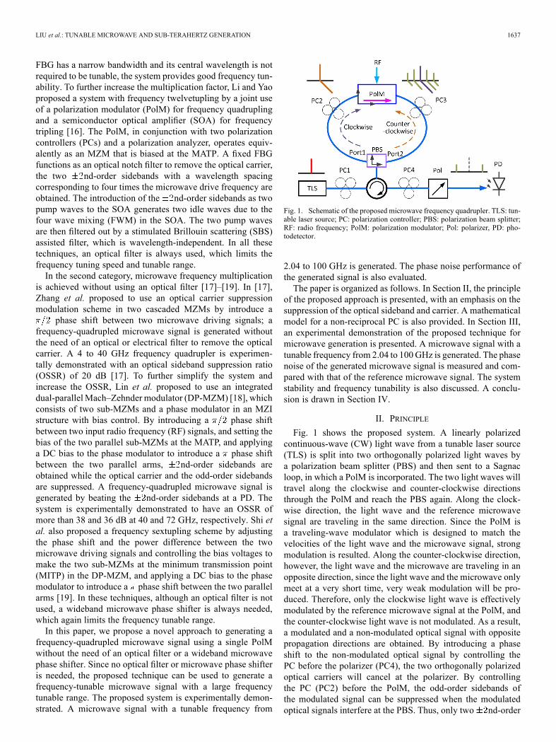
Fig. 1. Schematic of the proposed microwave frequency quadrupler. TLS: tun-able laser source; PC: polarization controller; PBS: polarization beam splitter;RF: radio frequency; PolM: polarization modulator; Pol: polarizer, PD: pho-todetector.
2.04 to 100 GHz is generated. The phase noise performance ofthe generated signal is also evaluated.The paper is organized as follows. In Section II, the principle
of the proposed approach is presented, with an emphasis on thesuppression of the optical sideband and carrier. A mathematicalmodel for a non-reciprocal PC is also provided. In Section III,an experimental demonstration of the proposed technique formicrowave generation is presented. A microwave signal with atunable frequency from 2.04 to 100 GHz is generated. The phasenoise of the generated microwave signal is measured and com-pared with that of the reference microwave signal. The systemstability and frequency tunability is also discussed. A conclu-sion is drawn in Section IV.
II. PRINCIPLE
Fig. 1 shows the proposed system. A linearly polarizedcontinuous-wave (CW) light wave from a tunable laser source(TLS) is split into two orthogonally polarized light waves bya polarization beam splitter (PBS) and then sent to a Sagnacloop, in which a PolM is incorporated. The two light waves willtravel along the clockwise and counter-clockwise directionsthrough the PolM and reach the PBS again. Along the clock-wise direction, the light wave and the reference microwavesignal are traveling in the same direction. Since the PolM isa traveling-wave modulator which is designed to match thevelocities of the light wave and the microwave signal, strongmodulation is resulted. Along the counter-clockwise direction,however, the light wave and the microwave are traveling in anopposite direction, since the light wave and the microwave onlymeet at a very short time, very weak modulation will be pro-duced. Therefore, only the clockwise light wave is effectivelymodulated by the reference microwave signal at the PolM, andthe counter-clockwise light wave is not modulated. As a result,a modulated and a non-modulated optical signal with oppositepropagation directions are obtained. By introducing a phaseshift to the non-modulated optical signal by controlling thePC before the polarizer (PC4), the two orthogonally polarizedoptical carriers will cancel at the polarizer. By controllingthe PC (PC2) before the PolM, the odd-order sidebands ofthe modulated signal can be suppressed when the modulatedoptical signals interfere at the PBS. Thus, only two nd-order

1638 JOURNAL OF LIGHTWAVE TECHNOLOGY, VOL. 31, NO. 10, MAY 15, 2013
Fig. 2. Sidebands suppression with polarization modulation.
sidebands are obtained at the output of the polarizer, whichare applied to a PD to generate a microwave signal with afrequency that is four times that of the reference microwavesignal.We start our analysis from the sideband suppression by using
a PolM jointly with a PC and a polarizer. Then, a mathematicalmodel for a fiber-optic PC used in the proposed system is devel-oped. Finally, an analysis on the suppression of odd-sidebandsand the optical carrier is provided.
A. Sideband Suppression
The PolM used in our proposed system is a special phasemodulator that supports both TE and TM modes with oppositephase modulation indexes [20]. The joint operation of a PolM, aPC and a polarizer is equivalent to an MZM with the bias pointbeing controlled by adjusting the phase difference between thetwo orthogonal modes via tuning the PC.Fig. 2 shows the operation of a PolM as an MZM. A linearly
polarized light wave from a TLS is applied to the PolM with itsstate of polarization (SOP) aligned at an angle of 45 relativeto one principal axis of the PolM, so the light wave is equallyprojected to the two orthogonal directions. Mathematically, theelectrical field at the output of the PolM along its principal axes(x and y) can be expressed as
(1)
where is the amplitude of the input optical field, is the an-gular frequency of the optical carrier, is the phase modulationindex, and is the angular frequency of the microwave signalapplied to the PolM. At the output of the PolM, the two modu-lated light waves are sent to a polarizer via a PC. The principalaxis of the polarizer is aligned at 45 relative to the x axis of thePolM. Thus, the electrical field at the output of the polarizer isgiven by
(2)
where is a static phase term introduced by the PC placed be-fore the polarizer. Thus, by substituting (1) into (2), we have
(3)
As can be seen (3) is exactly an expression for a standardMZM with a 1:1 splitting ratio for the two Y junctions. This
confirms that a PolM in conjunction with a PC and a polarizeris equivalent to an MZM with the bias controlled by the PC.Then, (3) is expanded in terms of Bessel functions of the firstkind, which is given in (4),
(4)
where represents the th-order Bessel functionsof the first kind. As can be seen, the odd-order sidebandsare suppressed when , and theeven-order sidebands are suppressed when
. Theoretically, odd- or even-order sidebands canbe suppressed with an infinite OSSR by changing the phasedifference, , between the TE and the TM modes.There are two ways to introduce a tunable phase difference
between the TE and the TM modes. One is to tune the PC be-fore the polarizer; the other is to apply a tunable DC voltage tothe bias of the PolM. Since the static phase term, , can be in-troduced before or after the PolM, the PC shown in Fig. 2 canalso be placed before the PolM to achieve the same sidebandssuppression. In our proposed system in Fig. 1, instead of usinga DC bias, PC2 is tuned to introduce a tunable phase differencebetween the two orthogonal modes.
B. The PC Model
Since PCs are playing an important role in the proposedsystem, the mathematical model for a PC is developed. Anin-line fiber-optic PC consists of three fiber birefringencecomponents; the first and the last are quarter-wave plates andthe central one is a half-wave plate. With this combination, anyinput SOP can be transformed to any other output SOP [21].Thus, a PC could be written as a fully tunable wave plate (seeAppendix)
(5)

LIU et al.: TUNABLE MICROWAVE AND SUB-TERAHERTZ GENERATION 1639
Fig. 3. Polarization status changes of both the clockwise and counter-clock-wise propagation waves, where is the accumulated static phase differencebetween the two orthogonal components.
where is the rotation angle, and is the phase difference be-tween the two orthogonal components introduced by the PC.If the same light is incident from the other side, the backwardtransfer function is given by
(6)
This model will be applied to the analysis of the proposedsystem.
C. Frequency Quadrupling
As discussed in Subsections A and B, simultaneous suppres-sion of the first-order sidebands and the optical carrier is achiev-able using the proposed system shown in Fig. 1. Assuming thatthe SOP of the incident light from the TLS is aligned at an angleof relative to one principal axis of the PBS, we have the clock-wise and counter-clockwise electrical fields given by
(7)
where and are the electrical fields of the clockwiseand counter-clockwise light waves, respectively, and
is the electrical field of the light wave from theTLS. To assist the analysis of the SOP change in the proposedsystem, the principal axes of the polarization devices, the PCs,PBS, and PolM, are shown in Fig. 3 with the SOP of light prop-agating along the loop in the same Cartesian coordinate system.As can be seen from Fig. 3, the principal axes of the PCs andthe PolM match with each other without angle rotation, and oneof these principal axes pairs is set to be the reference Cartesiancoordinates. The principal axes of the PBS are assumed alignedat 45 relative to the reference Cartesian coordinates, which canbe achieved in the experiment by tuning PC2 and PC3.For the clockwise light wave, it is modulated by the reference
microwave signal applied to the PolM when it passes through
the PolM. According to the discussion in Subsection A, theclockwise light wave at the output of the PolM can be written as
(8)
where is the clockwise light wave at the output of thePolM, and is the forward transfer function of PC2,
, and is the phase differencebetween the two orthogonal components induced by PC2. If (8)is expanded in terms of Bessel functions of the first kind, ig-noring the third- and higher order sidebands considering smallsignal modulation, (8) can be written as
(9.a)
(9.b)
To obtain a maximum power reception at the PBS for thereturn light waves, a third PC, PC3, is placed before the PBS,which is used to rotate the incoming light wave by 90 as shownin Fig. 3. According to (5), we have,
(10)
where is the electrical filed at the output of PC3 for theclockwise light wave, and is the forward transferfunction of PC3. Thus, the two orthogonal components of theclockwise light wave would interfere at port 2 of the PBS, andits output is given by
(11)
Substituting (7), (9.a), (9.b), and (10) into (11), we have
(12)
To suppress the first order sidebands, we must have
(13)
1640 JOURNAL OF LIGHTWAVE TECHNOLOGY, VOL. 31, NO. 10, MAY 15, 2013
Thus, (12) can be written as
(14)
Since the reference microwave signal is not modulated onthe counter-clockwise light wave due to the velocity mismatchat the PolM, we have the counter-clockwise light wave at theoutput of PC2, given by
(15)
where . Therefore, the elec-trical filed of the counter-clockwise light wave at the output ofport 1 of the PBS is given as
(16)
Since the clockwise and counter-clockwise light waves,and , are combined at the PBS, and
and are orthogonal at the output of the PBS. Byconnecting a fourth PC, PC4, and a polarizer after the PBS, andthe principal axis of the polarizer is aligned at an angle of toone principal axis of the PBS, we have the light wave at theoutput of the polarizer, written as
(17)
where is the phase difference between andintroduced by PC4. By tuning PC4, the two orthogonal propaga-tion waves can have an arbitrary phase difference. Substituting(7), (14) and (16) into (17), we have
(18)
To suppress the optical carrier, we must have
(19)
Thus,
(20)
Therefore, the output at the polarizer is, (if )
(21)
By applying to a high-speed PD, a microwave signalwith an angular frequency of is obtained.
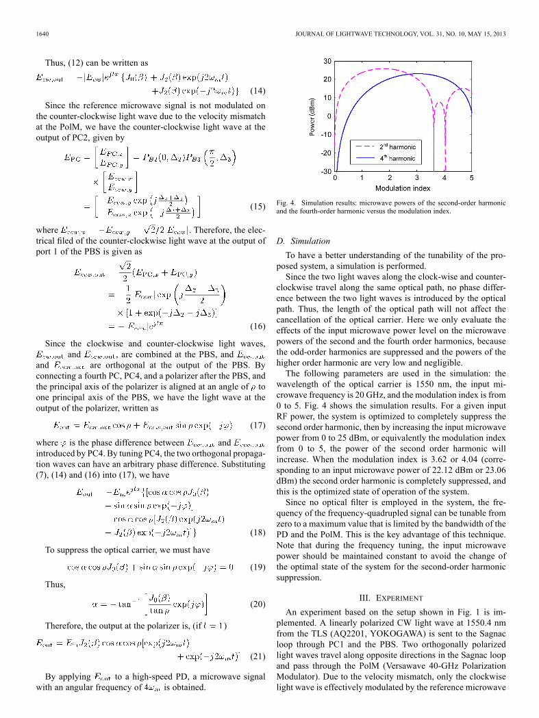
Fig. 4. Simulation results: microwave powers of the second-order harmonicand the fourth-order harmonic versus the modulation index.
D. Simulation
To have a better understanding of the tunability of the pro-posed system, a simulation is performed.Since the two light waves along the clock-wise and counter-
clockwise travel along the same optical path, no phase differ-ence between the two light waves is introduced by the opticalpath. Thus, the length of the optical path will not affect thecancellation of the optical carrier. Here we only evaluate theeffects of the input microwave power level on the microwavepowers of the second and the fourth order harmonics, becausethe odd-order harmonics are suppressed and the powers of thehigher order harmonic are very low and negligible.The following parameters are used in the simulation: the
wavelength of the optical carrier is 1550 nm, the input mi-crowave frequency is 20 GHz, and the modulation index is from0 to 5. Fig. 4 shows the simulation results. For a given inputRF power, the system is optimized to completely suppress thesecond order harmonic, then by increasing the input microwavepower from 0 to 25 dBm, or equivalently the modulation indexfrom 0 to 5, the power of the second order harmonic willincrease. When the modulation index is 3.62 or 4.04 (corre-sponding to an input microwave power of 22.12 dBm or 23.06dBm) the second order harmonic is completely suppressed, andthis is the optimized state of operation of the system.Since no optical filter is employed in the system, the fre-
quency of the frequency-quadrupled signal can be tunable fromzero to a maximum value that is limited by the bandwidth of thePD and the PolM. This is the key advantage of this technique.Note that during the frequency tuning, the input microwavepower should be maintained constant to avoid the change ofthe optimal state of the system for the second-order harmonicsuppression.
III. EXPERIMENT
An experiment based on the setup shown in Fig. 1 is im-plemented. A linearly polarized CW light wave at 1550.4 nmfrom the TLS (AQ2201, YOKOGAWA) is sent to the Sagnacloop through PC1 and the PBS. Two orthogonally polarizedlight waves travel along opposite directions in the Sagnac loopand pass through the PolM (Versawave 40-GHz PolarizationModulator). Due to the velocity mismatch, only the clockwiselight wave is effectively modulated by the reference microwave

LIU et al.: TUNABLE MICROWAVE AND SUB-TERAHERTZ GENERATION 1641
Fig. 5. Experimental results. The blue dashed curve shows the spectrum of themodulated optical signal without sideband suppression while the red solid curveshows the spectrum of the modulated optical signal with both carrier and first-order sideband suppressed. The modulation microwave signal has a frequencyof 10 GHz.
signal applied to the PolM, and the counter-clockwise propa-gation light wave is not modulated. As a result, a modulatedand a non-modulated optical signal with opposite propagationdirections are obtained. By controlling PC2 and PC3, the odd-order sidebands of the modulated signal are suppressed at thePBS, while the non-modulated optical signal would have aphase difference with the modulated optical carrier by control-ling PC4, to cancel the optical carrier in the modulated opticalsignal. Two nd-order sidebands are obtained at the polarizer,which are applied to a PD and a microwave signal with a fre-quency that is four times that of the reference microwave signalis generated.
A. Microwave Signal Generation
In the first experiment, a reference microwave signal of10 GHz from a signal generator (Agilent E8254A) is appliedto the PolM. The power of the input microwave is 22.6 dBmwhich is the maximum power available from the signal gen-erator and is close to the optimal input power to achieve acomplete suppression of the second order harmonic. In theexperiment, the principal axis of the polarizer is aligned at 45relative to one principal axis of the PBS, and PC4 is adjustedto introduce a phase shift between the two orthogonal lightwaves. To cancel the optical carrier, the optical carriers in bothdirections from the two ports of the PBS must have the sameamplitude when they return to the PBS. Thus, according to(20), the incident light must be aligned at an angle of relativeto one principal axis of the PBS, which is calculated to be
(22)
By tuning PC1 and PC4 to achieve the optical carrier suppres-sion, while the odd-order sidebands suppression are achieved bytuning PC2 and PC3, an optical signal with only the nd-orderis generated. The optical spectrum of the optical signal at theoutput of the polarizer is shown in Fig. 5. As can be seen, theoptical carrier is suppressed by 42 dB, and the first-order side-bands are suppressed by more than 32 dB. By beating the twond-order sidebands at a PD (U2T XPDV2150R-VF-VA, 50
GHz), a microwave signal with a frequency that is four times
Fig. 6. Electrical spectrum of the generated microwave signal when the refer-ence microwave signal is at 10 GHz.
Fig. 7. Optical spectra of the generated frequency-quadrupled microwave sig-nals at different frequencies of 5 GHz, 10 GHz, 15 GHz and 25 GHz of thereference microwave signal.
that of the reference microwave signal is generated. The spec-trum of the generated microwave signal is measured by an elec-trical spectrum analyzer (ESA, E4448A, Agilent), as shown inFig. 6. As can be seen, the power difference between the fre-quency-quadrupled signal and the highest unwanted harmonicis 17.8 dB.
B. Stability and Tunability
Another important feature of the proposed system is the ex-cellent short-term stability. Since the two counter propagationlight waves are traveling within the same optical loop, the twolight waves are experiencing the same perturbations and can becancelled out at the PD, which ensures an excellent short-termstability. This conclusion is justified by the experiment. At roomtemperature in a laboratory environment, the system is allowedto operate for more than five hours with the spectrum of the gen-erated microwave signal monitored by the ESA. Negligible am-plitude variations are observed. The long term stability may beaffected due to the use of the multiple PCs. For real applications,the system can be implemented using polarization maintainingcomponents and the PCs are not needed.To further evaluate the system performance of the proposed
technique, frequency tunability is investigated. One significantfeature of the proposed technique is the frequency independenttuning due to the elimination of an optical filter and a microwavephase shifter. To evaluate the frequency tuning independence,we tune the frequency of the reference microwave signal from5 to 25 GHz while keeping the microwave power unchanged(22.6 dBm). The optical spectra are shown in Fig. 7. As can beseen, when the frequency of the reference microwave signal istuned, the carrier and the first-order sidebands are maintainedsuppressed with no need to fine tune the system. It can be seenthat the system can achieve frequency quadrupling with a refer-ence microwave signal at different frequencies while the otherparameters (the setting of PC1, PC2, PC3, and PC4, and inputmicrowave power) remain unchanged. This important featuremakes the proposed system greatly simplified for the genera-tion of a widely frequency-tunable microwave signal.

1642 JOURNAL OF LIGHTWAVE TECHNOLOGY, VOL. 31, NO. 10, MAY 15, 2013
Fig. 8. The spectra of the generated microwave signals for a reference mi-crowave signal at different frequencies of (a) 510 MHz, (b) 800 MHz, (c) 2GHz, (d) 17 GHz, and (e) 25 GHz.
Fig. 8 shows the frequency tuning with a wider tunable rangefrom 2.04 to 100 GHz when the frequency of the reference mi-crowave signal is tuned from 510 MHz to 25 GHz with an iden-tical microwave power of 22.6 dBm applied to the PolM. Again,a frequency-quadrupled signal is generated for the reference mi-crowave signal at different frequencies. Note that the 100 GHzsignal is detected by a different PD (U2T XPDV4120R, 100GHz) with a wider bandwidth. Again, since no optical filter ormicrowave phase shifter is used, the tunable range is only lim-ited by the bandwidths of the PolM and the PD.
C. Phase Noise
The power spectrum of the phase noise in a frequency-multi-plied microwave signal can be expressed as [22]
(23)
where is the frequency multiplication factor, and andare the power spectra of the residual phase noise of the
system and of the microwave drive signal, respectively. In ourproposed system, .To evaluate the phase noise performance, the phase noises
of a reference microwave signal at 10 GHz and that of a fre-quency-quadrupled microwave signal at 40 GHz are measuredby a signal source analyzer (Agilent E5052B), which are shown
Fig. 9. Measured phase noises at driving signal of 10 GHz.
Fig. 10. Measured phase noises at different frequencies.
in Fig. 9. It can be seen that the phase noise of the frequency-quadrupled microwave signal is deteriorated by about 12.8 dBcompared to that of the reference microwave signal, which in-dicates that the phase noise of the frequency- quadrupled signalis mainly from the reference microwave signal in addition tothe 12 dB deterioration due to the frequency quadrupling oper-ation. The system induced phase noise, , is small and canbe neglected. The phase noise of the frequency-quadrupled mi-crowave signal at other frequencies is also measured, as shownin Fig. 10. As can be seen the phase noise at other frequenciesis also mainly from the reference microwave signal and the fre-quency quadrupling operation.
IV. CONCLUSION
We have proposed and experimentally demonstrated a newapproach to achieving microwave frequency quadrupling usingonly one PolM without using an optical filter or a microwavephase shifter. The functionality is achieved due to the bidirec-tional use of the PolM which can perform effective modulationfor a light wave along the clock-wise direction while no modu-lation is impressed on a light wave along the counter-clockwisedirection due to the velocity mismatch. The key significance of

LIU et al.: TUNABLE MICROWAVE AND SUB-TERAHERTZ GENERATION 1643
(A.4)
(A.5)
Fig. 11 An in-line fiber optic PC consisting of three wave plates. QWP: quarterwave plate; HWP: half wave plate.
the proposed system is the frequency independent tuning due tothe elimination of both an optical filter and a microwave phaseshifter. Thus, the proposed system can be used to generate a mi-crowave signal with a large tunable range. In addition, becauseof the use of a Sagnac loop, where the two counter travelinglight waves are traveling within the same fiber loop, high systemstability is ensured. The proposed system was theoretically an-alyzed and experimentally demonstrated. A frequency-quadru-pled microwave signal with a frequency tunable from 2.04 to100 GHz was demonstrated.
APPENDIX
A fiber-optic PC, shown in Fig. 11, consists of a quarter-wave,a half-wave, and a quarter-wave plates [20]. Any input SOP canbe transformed to any other output SOP by jointly adjustingthe , and plates. The rotation of a classical half-wave or a quarter-wave plate with respect to the incident lightis functionally equivalent to the rotation of the fiber loop, whichrotates the principle axes of the birefringent fiber sections withrespect to the input polarization state.The transfer function of a PC for a forward incident light
could is given [23]
(A.1)
where is the rotation angle, and is the phase difference be-tween the two orthogonal components introduced by the bire-fringence in a PC. For a backward incident light [24], we have
(A.2)
where is the transpose of . Generally, a polarized lightcould be expressed in a Jones vector:
(A.3)
where and are the amplitude of the orthogonal compo-nents, is the phase difference between the two orthogonal com-ponents. If the light is forwarded into the PC, we have (A.4),shown at the top of the page. If the light is back-warded into thePC with the same status, we have (A.5), shown at the top of thepage.
REFERENCES[1] A. J. Seeds and K. J. Williams, “Microwave photonics,” J. Lightw.
Technol., vol. 24, no. 12, pp. 4628–4641, Dec. 2006.[2] L. Goldberg, H. F. Taylor, J. F. Weller, and D. M. Bloom, “Microwave
signal generation with injection locked laser diodes,” Electron. Lett.,vol. 19, no. 13, pp. 491–493, Jun. 1983.
[3] L. Goldberg, A. Yurek, H. F. Taylor, and J. F. Weller, “35 GHz mi-crowave signal generation with injection locked laser diode,” Electron.Lett., vol. 21, no. 18, pp. 714–715, Aug. 1985.
[4] Z. Deng and J. P. Yao, “Photonic generation of microwave signal usinga rational harmonic mode-locked fiber ring laser,” IEEE Trans. Mi-crow. Theory Tech., vol. 54, no. 2, pp. 763–767, Feb. 2006.
[5] A. C. Bordonalli, B. Cai, A. J. Seeds, and P. J. Williams, “Generationof microwave signals by active mode locking in a gain bandwidth re-stricted laser structure,” IEEE Photon. Technol. Lett., vol. 8, no. 1, pp.151–153, Jan. 1996.

1644 JOURNAL OF LIGHTWAVE TECHNOLOGY, VOL. 31, NO. 10, MAY 15, 2013
[6] U. Gliese, T. N. Nielsen, M. Bruun, E. L. Christensen, K. E. Stubkjær,S. Lindgren, and B. Broberg, “A wideband heterodyne optical phaselocked loop for generation of 3–18 GHz microwave carriers,” IEEEPhoton. Technol. Lett., vol. 4, pp. 936–938, Aug. 1992.
[7] Z. Fan and M. Dagenais, “Optical generation of a mHz-linewidth mi-crowave signal using semiconductor lasers and a discriminator-aidedphase-locked loop,” IEEE Trans. Microw. Theory Tech., vol. 45, no. 8,pp. 1296–1300, Aug. 1997.
[8] X. Chen, Z. Deng, and J. P. Yao, “Photonic generation of microwavesignal using a dual-wavelength single-longitudinal-mode fiber ringlaser,” IEEE Trans. Microw. Theory Tech., vol. 54, no. 2, pp. 804–809,Feb. 2006, pt. 2.
[9] J. Sun, Y. Dai, Y. Zhang, X. Chen, and S. Xie, “Stable dual-wavelengthDFB fiber laser with separate resonant cavities and its application intunable microwave generation,” IEEE Photon. Technol. Lett., vol. 18,no. 24, pp. 2587–2589, Dec. 15, 2006.
[10] F. Van Dijk, A. Accard, A. Enard, O. Drisse, D. Make, and F. Lelarge,“Monolithic dual wavelength DFB lasers for narrow linewidth het-erodyne beat-note generation,” in Proc. MWP/APMP, Oct. 2011, pp.73–76.
[11] W. Li and J. P. Yao, “Investigation of photonically assisted microwavefrequency multiplication based on external modulation,” IEEE Trans.Microw. Theory Tech., vol. 58, no. 11, pp. 3259–3268, Nov. 2010.
[12] J. J. O’Reilly, P. M. Lane, R. Heidemann, and R. Hofstetter, “Opticalgeneration of very narrow linewidth millimeter wave signals,” Elec-tron. Lett., vol. 28, pp. 2309–2310, Dec. 1992.
[13] J. J. O’Reilly and P. M. Lane, “Fiber-supported optical generationand delivery of 60 GHz signals,” Electron. Lett., vol. 30, no. 16, pp.1329–1330, Aug. 1994.
[14] P. Shen, N. J. Gomes, P. A. Davies, W. P. Shillue, P. G. Huggard,and B. N. Ellison, “High-purity millimeter-wave photonic local oscil-lator generation and delivery,” in Proc. Int. Microw. Photon. TopicalMeeting, Sep. 10–12, 2003, pp. 189–192.
[15] G. Qi, J. P. Yao, J. Seregelyi, C. Bélisle, and S. Paquet, “Generationand distribution of a wideband continuously tunable millimeter-wavesignal with an optical external modulation technique,” IEEE Trans. Mi-crow. Theory Tech., vol. 53, no. 10, pp. 3090–3097, Oct. 2005.
[16] W. Li and J. P. Yao, “Microwave and terahertz generation based onphotonically assisted microwave frequency twelvetupling with largetunability,” IEEE Photon. J., vol. 2, no. 6, pp. 954–959, Dec. 2010.
[17] J. Zhang, H. Chen, M. Chen, T. Wang, and S. Xie, “A photonicmicrowave frequency quadrupler using two cascaded intensity mod-ulators with repetitious optical carrier suppression,” IEEE Photon.Technol. Lett., vol. 19, no. 14, pp. 1057–1059, Jul. 2007.
[18] C. T. Lin, P. T. Shih, J. Chen, W. Q. Xue, P. C. Peng, and S. Chi, “Op-tical millimeter-wave signal generation using frequency quadruplingtechnique and no optical filtering,” IEEE Photon. Technol. Lett., vol.20, no. 12, pp. 1027–1029, Jun. 15, 2008.
[19] P. Shi, S. Yu, Z. Li, S. Huang, J. Shen, Y. Qiao, J. Zhang, andW.Gu, “Afrequency sextupling scheme for high-quality optical millimeter-wavesignal generation without optical filter,” Opt. Fiber Technol., vol. 17,no. 3, pp. 236–241, May 2011.
[20] J. D. Bull, N. A. F. Jaeger, H. Kato, M. Fairburn, A. Reid, and P.Ghanipour, “40 GHz electro-optic polarization modulator for fiberoptic communications systems,” in Proc. SPIE, 2004, vol. 5577, pp.133–143.
[21] B. G. Koehler and J. E. Bowers, “In-line single-mode fiber polarizationcontrollers at 1.55, 1.3, and 0.63 m,” Appl. Opt., vol. 24, no. 3, pp.349–353, Feb. 1985.
[22] R. T. Logan, Jr., “All-optical heterodyne RF signal generation using amode-locked-laser frequency comb: Theory and experiments,” in IEEEMTT-S Int. Microw. Symp. Dig., 2000, vol. 3, pp. 1741–1744.
[23] S. Pan and J. P. Yao, “UWB over fibre communications: Modulationand transmission,” J. Lightw. Technol., vol. 28, no. 16, pp. 2445–2455,Aug. 2010.
[24] S. Feng, Q. Mao, L. Shang, and J. W. Y. Lit, “Reflectivity charac-teristics of the fiber loop mirror with a polarization controller,” Opt.Commun., vol. 277, no. 2, pp. 322–328, Sep. 15, 2007.
Weilin Liu (S’10) received the B.Eng. degree in electronic information engi-neering from the University of Science and Technology of China, Hefei, China,in 2009, and the M.A.Sc. degree in electrical and computer engineering in theSchool of Electrical Engineering and Computer Science, University of Ottawa,Ottawa, ON, Canada, in 2011.He is currently working in the Microwave Photonics Research Laboratory,
School of Electrical Engineering and Computer Science, University of Ottawa,Ottawa, ON, Canada. His research interests include microwave/terahertz gen-eration, optical signal processing, fiber Bragg grating and their applications inmicrowave photonic systems.
Muguang Wang received the B.S. degree in optics from Shandong University,Jinan, China, in 1999, and the Ph.D. degree in electrical engineering from Bei-jing Jiaotong University, Beijing, China, in 2004.In 2004, he joined the Institute of Lightwave Technology, Key Lab of All
Optical Network and Advanced Telecommunication Network of EMC, BeijingJiaotong University, Beijing, China, as a Lecturer, where he has been an Asso-ciate Professor since 2006. Since January 2012, he has been a visiting researcherwith the Microwave Photonics Research Laboratory, School of Electrical Engi-neering and Computer Science, University of Ottawa, Ottawa, ON, Canada. Hiscurrent research interests include optical fiber communications and networking,microwave photonics, and optical signal processing.
Jianping Yao (M’99–SM’01–F’12) joined the School of Electrical Engineeringand Computer Science, University of Ottawa, Ottawa, Ontario, Canada, as anAssistant Professor in 2001, where he became an Associate Professor in 2003,and a Full Professor in 2006.He was appointed University Research Chair in Microwave Photonics in
2007. From July 2007 to June 2010, he was the Director of the Ottawa-CarletonInstitute for Electrical and Computer Engineering. Prior to joining the Univer-sity of Ottawa, he was an Assistant Professor in the School of Electrical andElectronic Engineering, Nanyang Technological University, Singapore, from1999 to 2001. He received the Ph.D. degree in electrical engineering from theUniversité de Toulon, Toulon, France, in December 1997. He has publishedmore than 400 papers, including more than 220 papers in peer-reviewed jour-nals and 180 papers in conference proceedings. His research interests focus onmicrowave photonics, which includes photonic processing of microwave sig-nals, photonic generation of microwave, millimeter-wave and terahertz, radioover fiber, ultrawideband over fiber, and photonic generation of microwavearbitrary waveforms. His research also covers fiber optics and biophotonics,which includes fiber lasers, fiber and waveguide Bragg gratings, fiber-opticsensors, microfluidics, optical coherence tomography, and Fourier-transformspectroscopy.Dr. Yao is currently an Associate Editor of the International Journal of Mi-
crowave and Optical Technology. He is on the Editorial Board of the IEEETRANSACTIONS ONMICROWAVE THEORY AND TECHNIQUES. He is a Chair of nu-merous international conferences, symposia, and workshops, including the ViceTechnical Program Committee (TPC) Chair of the IEEE Microwave PhotonicsConference in 2007, TPC Co-Chair of the Asia-Pacific Microwave PhotonicsConference in 2009 and 2010, TPC Chair of the high-speed and broadbandwireless technologies subcommittee of the IEEE Radio Wireless Symposium in2009–2012, TPC Chair of the microwave photonics subcommittee of the IEEEPhotonics Society Annual Meeting in 2009, TPC Chair of the IEEE MicrowavePhotonics Conference in 2010, and General Co-Chair of the IEEE MicrowavePhotonics Conference in 2011. He is also a committee member of numerousinternational conferences. Prof. Yao received the 2005 International CreativeResearch Award of the University of Ottawa. He was the recipient of the 2007George S. Glinski Award for Excellence in Research. In 2008, he was awarded aNatural Sciences and Engineering Research Council of Canada Discovery Ac-celerator Supplements Award. Prof. Yao was selected to receive an inauguralOSA Outstanding Reviewer Award in 2012. Currently, Prof. Yao serves as anIEEE Distinguished Microwave Lecturer for 2013–2015. Prof. Yao is a regis-tered Professional Engineer of Ontario. He is a Fellow of IEEE, a Fellow of theOptical Society of America (OSA), and a Fellow of the Canadian Academy ofEngineering (CAE).


