16127 Dansie Property Subdivision Geotech Report
29
GEOTECHNICAL ENGINEERING REPORT DANSIE PROPERTY SUBDIVISION PROPERTY LOCATION: 13400 SOUTH HAWTHORNE WAY RIVERTON, UT Prepared for: LOVELL DEVEOPMENT ATTN: BRETT LOVELL AUGUST 12, 2016
Transcript of 16127 Dansie Property Subdivision Geotech Report
GEOTECHNICAL ENGINEERING REPORT DANSIE PROPERTY SUBDIVISION
PROPERTY LOCATION: 13400 SOUTH HAWTHORNE WAY
RIVERTON, UT
Prepared for: LOVELL DEVEOPMENT ATTN: BRETT LOVELL
AUGUST 12, 2016
GEOTECHNICAL INVESTIGATION REPORT PROJECT NO. 16127 DANSIE PROPERTY SUBDIVISION RIVERTON, UTAH
1. INTRODUCTION ................................................................................................................................. 4
2. PURPOSE AND SCOPE .................................................................................................................... 4
3. SITE AND PROJECT INFORMATION ............................................................................................ 4
3.1. PROPOSED PROJECT DESCRIPTION .......................................................................................... 4 3.2 EXISTING SITE CONDITIONS ....................................................................................................... 4
4. SURFICIAL GEOLOGY ...................................................................................................................... 5
5. FIELD EXPLORATIONS .................................................................................................................... 5
5.1 SUBSURFACE INVESTIGATION .................................................................................................... 5 5.2 SUBSURFACE CONDITIONS ........................................................................................................ 5
5.2.1 Soils........................................................................................................................... 5 5.2.2 Groundwater ............................................................................................................. 5
6 LABORATORY TESTING .................................................................................................................. 6
7 RECOMMENDATIONS AND CONCLUSIONS .............................................................................. 6
7.1 GEOTECHNICAL DISCUSSION ..................................................................................................... 6 7.2 SITE WORK ................................................................................................................................. 6
7.2.1 Site Preparation ....................................................................................................... 6 7.2.2 Excavation Consideration ....................................................................................... 7 7.2.3 Cut and Fill ............................................................................................................... 7 7.2.4 Structural Fill Material ............................................................................................. 7 7.2.5 Fill Placement and Compaction ............................................................................. 8 7.2.6 Utility Trenches ........................................................................................................ 8 7.2.7 Native Soil As Fill ..................................................................................................... 9 7.2.8 Surface Drainage ..................................................................................................... 9
7.3 FOUNDATIONS ............................................................................................................................ 9 7.3.1 Installation and Bearing Material ........................................................................... 9 7.3.2 Bearing Pressure ................................................................................................... 10 7.3.3 Settlement ............................................................................................................... 10 7.3.4 Frost Depth ............................................................................................................. 10 7.3.5 Construction Observation .................................................................................... 10 7.3.6 Foundation Drainage ............................................................................................. 10
7.4 LATERAL FORCES .................................................................................................................... 11 7.4.1 Resistance for Footings ........................................................................................ 11 7.4.2 Lateral Earth Pressures on Foundation Walls .................................................... 11 7.4.3 Seismic Conditions ................................................................................................ 12
7.5 CONCRETE SLABS ON GRADE ................................................................................................. 13 7.6 SEISMIC INFORMATION ............................................................................................................. 13
7.6.1 Faulting ................................................................................................................... 13 7.6.2 Liquefaction ............................................................................................................ 14 7.6.3 Structures ............................................................................................................... 15
7.7 PAVEMENT DESIGN AND CONSTRUCTION ............................................................................... 15 7.7.1 Sub-grade Preparation .......................................................................................... 15 7.7.2 Base Course ........................................................................................................... 15 7.7.3 Surface Course ...................................................................................................... 16 7.7.4 Drainage and Maintenance ................................................................................... 16
8 LIMITATIONS AND PROFESSIONAL STATEMENT ................................................................. 16
GEOTECHNICAL INVESTIGATION REPORT PROJECT NO. 16127 DANSIE PROPERTY SUBDIVISION RIVERTON, UTAH
LIST OF TABLES AND FIGURES Table 7.2.4 Structural Fill Requirements Table 7.4.2 Static Conditions Table 7.4.3 Dynamic Conditions Table 7.6.1 USGS Earthquake Hazards Estimated Values Table 7.7.2 Pavement Design Recommended Thickness Figure 7.6 ASCE 7-05 Seismic Provisions APPENDIX
Vicinity Map Site Map with Test Pit Locations Unified Soil Classification System Chart Test Pit Logs (TP-1 through TP-5) Summary of Lab Test Results
Grain Size Distribution Consolidation Test Result
GEOTECHNICAL INVESTIGATION REPORT PROJECT NO. 16127 DANSIE PROPERTY SUBDIVISION AUGUST 12, 2016 RIVERTON, UTAH
4
1. INTRODUCTION
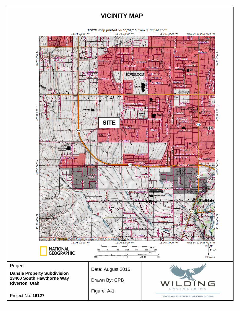
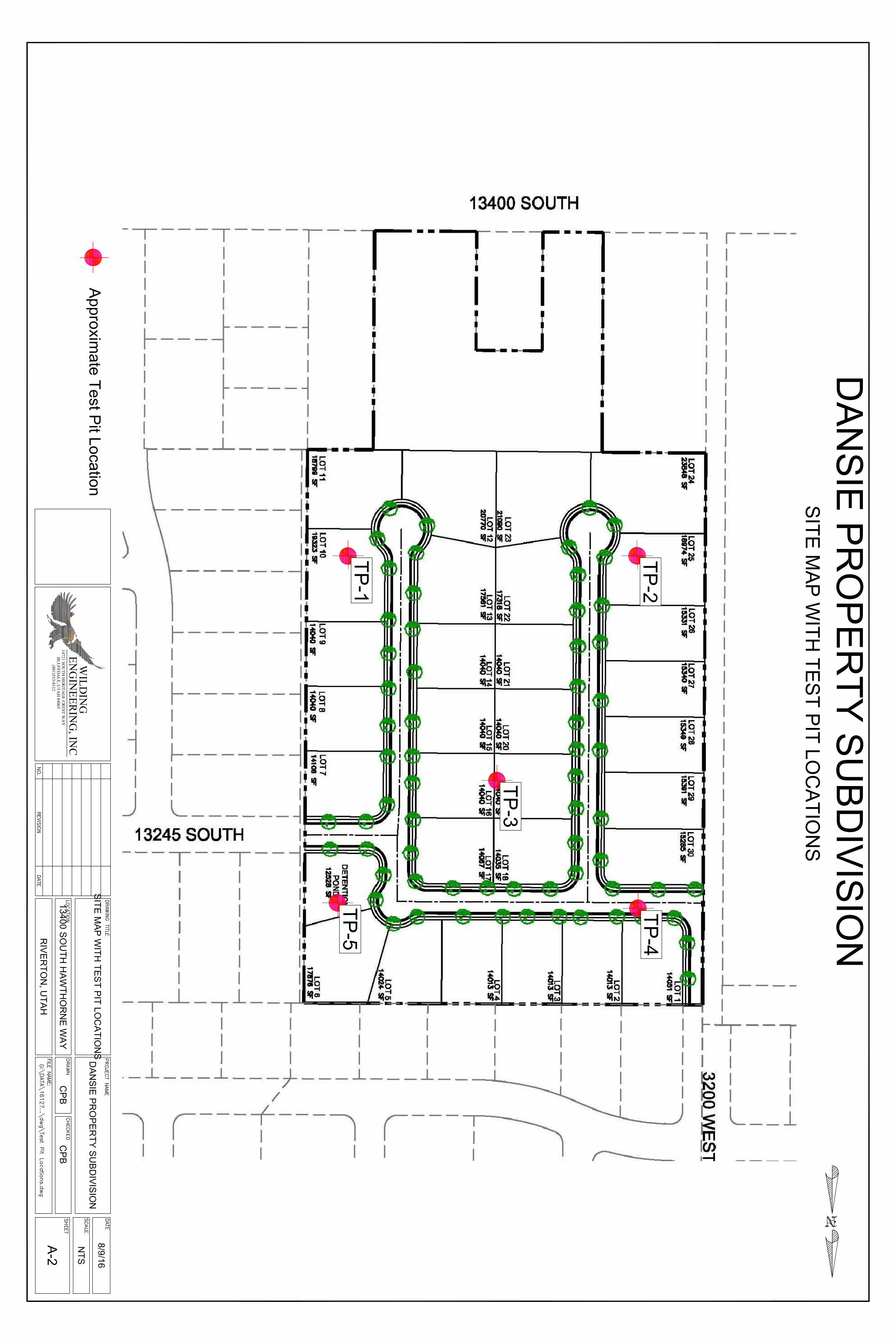
This report presents the geotechnical investigation for the proposed Dansie Property Subdivision to be located near the intersection of 13400 South Street and Hawthorne Way in Riverton, Utah as shown on the vicinity map in the Appendix. The geotechnical investigation was performed in accordance with Wilding Engineering’s proposal.
The field investigation consisted of five (5) test pits. Test Pits (TP-1 through TP-5) were excavated to depths ranging from 12 feet to 13 feet below the existing ground surface. Detailed test pit logs can be found in the Appendix. Recommendations in this report are based upon information gathered from the field investigation, site inspection, lab testing, and from reviewing geologic maps and reports of the area.
2. PURPOSE AND SCOPE
The purpose of this investigation was to determine the suitability of on-site soils for the development of a residential subdivision consisting of single family residences with the associated utilities, roadways, and driveways. The investigation includes a review of surface water and ground water conditions and their affects. Engineering and construction recommendations are presented based on subsurface conditions encountered in the field along with the effects of both subsurface and surface waters.
3. SITE AND PROJECT INFORMATION
3.1. Proposed Project Description
Based on our understanding of the project, the proposed development will consist of two story, single family residential buildings with the associated utilities and roadway. We understand the buildings will be constructed with typical wood framed walls with a 6 to 8-foot basement. The proposed site is approximately 17 acres in area and will consist of 30 lots. Loading information was not available at the time of this report. Based on our experience and understanding of the proposed construction, maximum column and wall loads are assumed to be about 50 kips and 4 kip/ft, respectively. A site map is located in the Appendix of this report.
Recommendations presented in this report are based upon the current available information. If the assumed building loads or any information presented is incorrect or has changed, please inform Wilding Engineering in writing so that we may amend the recommendations presented in this report appropriately.
3.2 Existing Site Conditions
The proposed residential subdivision consists of about 17 acres in area and is located near the northwest corner of the intersection of 13400 South Street and Hawthorne Way in Riverton, Utah. More specifically, the site is located at latitude 40.510083 degrees and Longitude -111.966119 degrees.
GEOTECHNICAL INVESTIGATION REPORT PROJECT NO. 16127 DANSIE PROPERTY SUBDIVISION AUGUST 12, 2016 RIVERTON, UTAH
5
At the time of our field investigation, the project site was a vacant agricultural land. Based on available topographic information, the subject site slopes downward to the east. The subject site is bounded by existing 13400 South Street on the south, vacant land on the west, and existing single family residences on the east and north sides.
4. SURFICIAL GEOLOGY
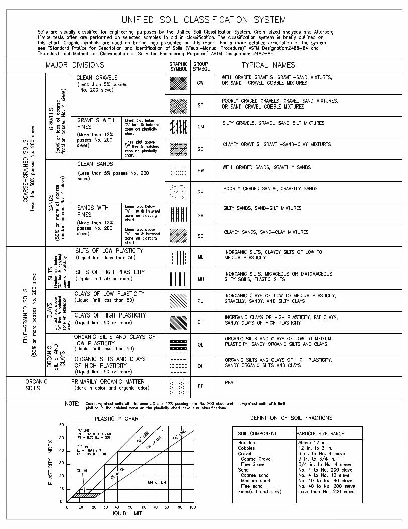
Based on the available geologic maps, the project site is underlain by lacustrine deposits. These deposits typically consist of silt and clay deposits. The soils encountered in the soil profile consisted of clayey soils.
5. FIELD EXPLORATIONS
5.1 Subsurface Investigation
Subsurface conditions at the project site were evaluated with five (5) test pits designated TP-1 through TP-5 as indicated on Site Map with Test Pit Locations presented in the Appendix. The test pits were excavated using a rubber-tired backhoe to depths ranging from 12 feet to 13 feet below the existing site grades. Stratigraphy and classification of the soils were logged under the direction of a geotechnical engineer.
Disturbed and undisturbed samples were obtained at various depths and examined in the field and representative portions were stored in sealed plastic bags. The samples were transported to our laboratory for further examination and testing. The test pits were backfilled to the ground surface with on-site soils. Sample types with depths are shown in detail in the Test Pit Logs found in the Appendix.
5.2 Subsurface Conditions
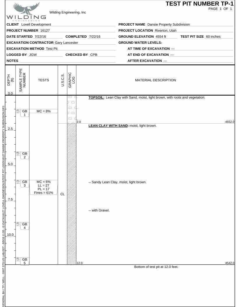
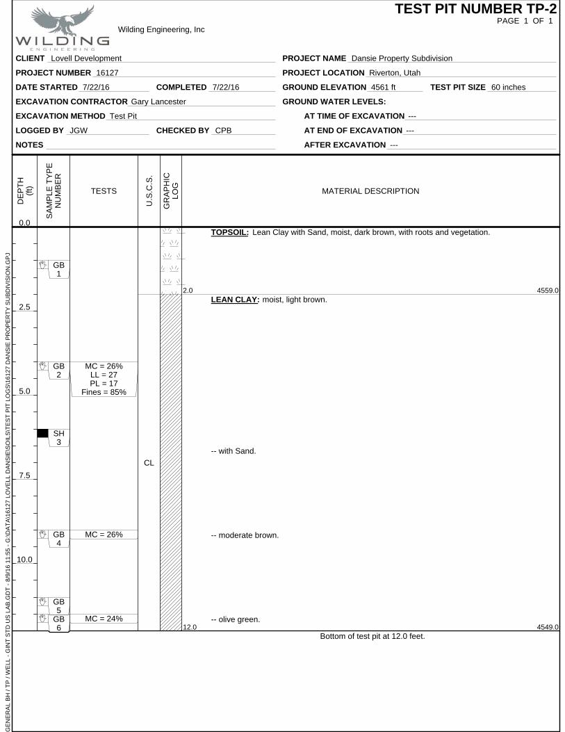
5.2.1 Soils The soil profile encountered in the test pits consisted of about 2 feet of topsoil underlain by Lean Clay (CL) with varying amounts of Sand to the maximum depth of exploration of 13 feet.
For a detailed description of the materials and conditions encountered at each test pit locations, please refer to the Test Pit Logs in the Appendix.
The subsurface profile descriptions above are a generalized interpretation provided to highlight the major subsurface stratification features and material characteristics. The test pit logs included in the Appendix should be reviewed for more specific information. The stratifications shown on the test pit logs represent the conditions only at each test pit log location. The stratifications represent the approximate boundary between subsurface materials and the transition may be gradual.
5.2.2 Groundwater Groundwater was not encountered during any of the test pits to the maximum depth of 13 feet. It should be noted that it is possible for the ground water levels to fluctuate
GEOTECHNICAL INVESTIGATION REPORT PROJECT NO. 16127 DANSIE PROPERTY SUBDIVISION AUGUST 12, 2016 RIVERTON, UTAH
6
during the year depending on the season and climate. Additionally, discontinuous zones of perched water may exist at various locations and depths beneath the ground surface. This could result in encountering ground water conditions during construction which may have been different than during our field investigation. If ground water is encountered at during construction, Wilding Engineering must be notified to amend our recommendations, as appropriate.
6 LABORATORY TESTING
Representative soil samples were tested to evaluate physical and engineering properties. Laboratory testing included: natural water content, unit weight, grain size analysis, Atterberg Limits and one-dimensional consolidation testing. Lab results are presented on the Test Pit Logs and Summary of Lab Results in the Appendix.
7 RECOMMENDATIONS AND CONCLUSIONS
7.1 Geotechnical Discussion Wilding Engineering, Inc. has provided the following geotechnical recommendations based on the information provided by the client and the soils encountered during our field investigation for the proposed development. The proposed site is suitable for construction if the recommendations of this report are adhered to. The primary geotechnical considerations with respect to the development include moisture sensitivity of the on-site fine-grained soils, foundation subgrade preparation, and surface drainage. Further information is provided in the following sections of this report.
7.2 Site Work
7.2.1 Site Preparation It is the contractor’s responsibility to locate and protect all existing utility lines, whether shown on the drawings or not.
About 2 feet of topsoil was encountered during our investigation. All existing vegetation, trees, roots, and topsoil shall be grubbed and removed from the site or stockpiled for use in landscaped areas. Deeper or shallower excavations may be required locally. Topsoil stockpile shall be a safe distance away from any on-site or imported fill material to prevent contamination.
Upon completion of site stripping and prior to placement of any fill material, the exposed subgrade should be evaluated by a representative of the Geotechnical Engineer. Proof rolling with construction equipment may be a part of this evaluation. Soils that are observed to rut or deflect excessively (typically greater than 1-inch) under the moving load of a loaded rubber-tired loaded dump truck (typically, 9 ton/axle) or other suitable construction vehicle should be over-excavated down to firm undisturbed native soils and backfilled with properly placed and compacted structural fill.
GEOTECHNICAL INVESTIGATION REPORT PROJECT NO. 16127 DANSIE PROPERTY SUBDIVISION AUGUST 12, 2016 RIVERTON, UTAH
7
If the subgrade is disturbed during construction, disturbed soils should be recompacted and tested or it should be over-excavated to firm, undisturbed soil and backfilled with compacted granular materials.
Footing excavations should be made using an excavator equipped with a smooth edge and supported from outside the excavation to minimize disturbance to the natural soil subgrade. If the subgrade is disturbed during construction, disturbed soils should be recompacted and tested or it should be over-excavated to firm, undisturbed soil and backfilled with compacted granular materials.
7.2.2 Excavation Consideration All utility excavations shall be carefully supported, maintained, and protected during construction in accordance with OSHA Regulations as stated in 29 CFR Part 1926. It is the responsibility of the contractor to have safe working conditions. Temporary construction excavations shall be properly sloped or shored, in compliance with current federal, state, and local requirements.
Construction excavations up to 4 feet deep may be constructed with near-vertical side slopes. Excavations between 4 feet and 10 feet deep shall have side slopes not steeper than 1H:2V, or a trench box or shoring may be used. Excavations are to be made to minimize subsequent filling. Coarse-grained material can easily become unstable and is anticipated in localized areas to experience toppling, cave-in or sliding. Boulders and cobbles larger than six inches shall be removed from trenches.
Wilding Engineering does not assume responsibility for construction site safety or the contractor's or other parties’ compliance with local, state, and federal safety or other regulations. As stated in the OSHA regulations, “a competent person shall evaluate the soil exposed in the excavations as part of his/her safety procedures”. In no case should slope height, slope inclination, or excavation depth, including utility trench excavation depth, exceed those specified in local, state, and federal safety regulations.
7.2.3 Cut and Fill Permanent cut and fill slopes not exceeding ten (10) feet in depths shall not be steeper than 2H:1V horizontal to vertical. If anticipated cut and fill heights exceed ten (10) feet, or slopes are required to exceed 2H:1V, we should be notified so that we can provide additional stability analysis and recommend improvements and slopes. It is recommended that permanent slopes be maintained and vegetated to prevent possible erosion.
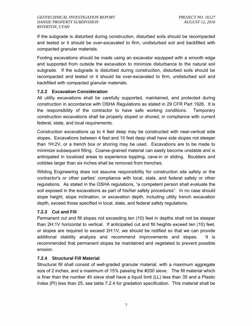
7.2.4 Structural Fill Material Structural fill shall consist of well-graded granular material, with a maximum aggregate size of 2 inches, and a maximum of 15% passing the #200 sieve. The fill material which is finer than the number 40 sieve shall have a liquid limit (LL) less than 35 and a Plastic Index (PI) less than 25, see table 7.2.4 for gradation specification. This material shall be
GEOTECHNICAL INVESTIGATION REPORT PROJECT NO. 16127 DANSIE PROPERTY SUBDIVISION AUGUST 12, 2016 RIVERTON, UTAH
8
free from organics, garbage, frost, and other loose, compressible, or deleterious materials.
Table 7.2.4 Structural Fill Requirements
Grain Size Percent Passing
2-inch 100
¾-inch 85 to 100
No. 4 15 to 45
No. 200 < 15
Plastic Index (PI) < 25
Liquid Limit (LL) < 35
Subsurface soils profile at the site predominantly consists of granular soils. These soils can be used as fill provided they do not contain material greater than 4 inches in size and the specified compaction requirements are achieved.
7.2.5 Fill Placement and Compaction Fill under footings, interior floor slabs, concrete flatwork, driveway, and utilities should be placed in nine (9) inch lifts (loose) and shall be compacted to at least 95% of the modified proctor (maximum dry density as determined by the ASTM D 1557 method of compaction). Landscaped areas are to be compacted to at least 90% of the modified proctor. Each lift shall be tested for adequate compaction (see section 7.3.1 for fill placement and compaction under foundations). Wilding Engineering can provide this service under an additional agreement.
7.2.6 Utility Trenches Construction of the pipe bedding shall consist of preparing an acceptable pipe foundation, excavating the pipe groove in the prepared foundation and backfilling from the foundation to 12 inches above the top of the pipe. All piping shall be protected from lateral displacement and possible damage resulting from impact or unbalanced loading during backfilling operations by being adequately bedded. In our experience individual municipalities will have local requirements regarding installation of utilities. However, in the absence of specified requirements the following is recommended:
The soils in the utility pipe trenches are to meet the specified structural fill requirements in Section 7.2.4.
Pipe foundation: shall consist of imported structural fill. Wherever the trench subgrade material does not afford a sufficiently solid foundation to support the pipe and superimposed load, the trench shall be excavated below the bottom of the pipe to such depth as may be necessary, to eliminate unstable soils and this
GEOTECHNICAL INVESTIGATION REPORT PROJECT NO. 16127 DANSIE PROPERTY SUBDIVISION AUGUST 12, 2016 RIVERTON, UTAH
9
additional excavation filled with compacted well-graded, granular soil (per 7.2.5), compacted to 95% of the modified proctor.
Pipe groove: shall be excavated in the pipe foundation to receive the bottom quadrant of the pipe so that the installed pipe will be true to line and grade. Bell holes shall be dug after the trench bottom has been graded. Bell holes shall be excavated so that only the barrel of the pipe bears on the pipe foundation.
Pipe bedding: (from pipe foundation to 12 inches above top of pipe) shall be deposited and compacted in layers not to exceed 9 inches in uncompacted depth. Deposition and compaction of bedding materials shall be done simultaneously and uniformly on both sides of the pipe. All bedding materials shall be placed in the trench in such a manner that they will be scattered alongside the pipe and not dropped into the trench in compact masses.
Backfill for utility trenches located beneath roadways shall be compacted to 95% of the modified proctor. In non-load bearing areas (landscape), trenches shall be compacted to 90% of the modified proctor (ASTM D 1557).
7.2.7 Native Soil As Fill
The native soils generally consist of cohesive soils in the upper 5 feet. Clayey and silty soils are generally not acceptable as fill, because of the difficulty in achieving compaction due to their moisture sensitivity. We recommend that a well-graded granular material be imported as per the gradation requirements presented in Table 7.2.4.
7.2.8 Surface Drainage A grading and drainage plan shall be prepared for the site by a qualified engineer and shall be followed for the site drainage. Generally, each building site shall be graded in such a manner that surface water will flow away from the buildings foundations. Natural drainage is generally from west to east. Surface water should be prevented from entering trenches during construction. An embankment may be used to divert any storm water from construction areas and directed into temporary retention basin.
7.3 Foundations
7.3.1 Installation and Bearing Material Footings must be placed entirely on firm undisturbed native soils or entirely on 2 feet of structural fill which is bearing on native soils (below the existing topsoil layer) and is compacted to 95% of the modified proctor (maximum dry density as determined with ASTM D1557 method of test). Any existing topsoil shall be removed from the areas where footings are to be located. All load bearing soils which are disturbed or considered soft or loose areas are unsuitable for support for foundations and should be removed down to firm native soils and properly replaced and compacted with structural fill within ±2% of the optimum moisture content. Bottom of footing must be at least 2 feet above groundwater level.
GEOTECHNICAL INVESTIGATION REPORT PROJECT NO. 16127 DANSIE PROPERTY SUBDIVISION AUGUST 12, 2016 RIVERTON, UTAH
10
All organic material, soft areas, frozen material or other inappropriate material shall be removed from the footing zone to a depth determined by the Geotechnical Engineer and be replaced with structural fill. Foundations shall have minimum dimensions of 18-inches wide for continuous wall footings and 24-inches square for isolated column footings correlating to the prescribed bearing pressure. Footings placed on slopes shall be “benched” so that all footing bases are horizontal and are not sloped.
Footing excavations shall be inspected by a Geotechnical Engineer prior to placement of structural fill, concrete or reinforcement steel to verify their suitability for placement of the footings.
7.3.2 Bearing Pressure
Based on our experience and understanding of the proposed construction, maximum column and continuous wall loads are assumed to be about 50 kips and 4 kip/ft, respectively. Footings bearing entirely on firm undisturbed native soils or entirely on structural fill may be designed with a maximum allowable bearing capacity of 2,000 pounds per square foot (psf), or a subgrade modulus value of 100 pounds per cubic inch (pci). Consolidation settlement was limited to 1 inch. The recommended allowable bearing pressure refers to the total dead load and may be increased by 1/3 to include the sum of all transient loads including wind and seismic.
7.3.3 Settlement
The total settlement is anticipated not to exceed 1-inch, which is the recommended maximum settlement for these types of structures. Differential settlement is expected to approach about 50 to 75 percent of the total settlement under static conditions.
7.3.4 Frost Depth All exterior footings are to be at least 30 inches below the ground surface to protect against possible frost heave. This includes walk-out areas. This may require fill to be placed around buildings. Slab on grade construction, interior footings require 18 inches of cover. If foundations are constructed through the winter months, all soils on which footings will bear shall be protected from freezing.
7.3.5 Construction Observation A geotechnical engineer shall periodically monitor excavations prior to installation of footings. Inspection of soil before placement of structural fill or concrete is required to detect any field conditions not encountered in the investigation, which would alter the recommendations of this report. All structural fill material shall be tested under direction of the geotechnical engineer for adequate compaction.
7.3.6 Foundation Drainage Wilding Engineering recommends footings and foundations be designed according to the International Building Code (IBC 2012). According to the IBC 2012, foundation drain shall be installed if the native soils have poor drainage characteristics, to allow water to drain away from the foundation. During our field investigation, soils encountered had
GEOTECHNICAL INVESTIGATION REPORT PROJECT NO. 16127 DANSIE PROPERTY SUBDIVISION AUGUST 12, 2016 RIVERTON, UTAH
11
significant amount of fines content. These soils are “not” considered “free draining”. We recommend that a footing drain be installed.
7.4 Lateral Forces
7.4.1 Resistance for Footings Wind and seismic forces, which cause lateral loads on foundations, are resisted by friction and passive earth pressures at the foundation ground interface. In the design of spread footings against shear forces, the total dead weight is multiplied by the coefficient of friction for lateral sliding (μ) which is estimated to be 0.25 for sands, and the resistance of lateral sliding is 130 psf for clays and silts. 1
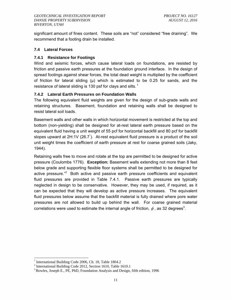
7.4.2 Lateral Earth Pressures on Foundation Walls The following equivalent fluid weights are given for the design of sub-grade walls and retaining structures. Basement, foundation and retaining walls shall be designed to resist lateral soil loads.
Basement walls and other walls in which horizontal movement is restricted at the top and bottom (non-yielding) shall be designed for at-rest lateral earth pressure based on the equivalent fluid having a unit weight of 55 pcf for horizontal backfill and 80 pcf for backfill slopes upward at 2H:1V (26.7°). At-rest equivalent fluid pressure is a product of the soil unit weight times the coefficient of earth pressure at rest for coarse grained soils (Jaky, 1944).
Retaining walls free to move and rotate at the top are permitted to be designed for active pressure (Coulombs 1776). Exception: Basement walls extending not more than 8 feet below grade and supporting flexible floor systems shall be permitted to be designed for active pressure.”2 Both active and passive earth pressure coefficients and equivalent fluid pressures are provided in Table 7.4.1. Passive earth pressures are typically neglected in design to be conservative. However, they may be used, if required, as it can be expected that they will develop as active pressure increases. The equivalent fluid pressures below assume that the backfill material is fully drained where pore water pressures are not allowed to build up behind the wall. For coarse grained material
correlations were used to estimate the internal angle of friction, , as 32 degrees3.
7 International Building Code 2006, Ch. 18, Table 1804.2 2 International Building Code 2012, Section 1610, Table 1610.1 3 Bowles, Joseph E., PE, PhD, Foundation Analysis and Design, fifth edition, 1996
GEOTECHNICAL INVESTIGATION REPORT PROJECT NO. 16127 DANSIE PROPERTY SUBDIVISION AUGUST 12, 2016 RIVERTON, UTAH
12
Table 7.4.2 Static Conditions
Equivalent Fluid Pressures and Coefficients
Conditions K K 2H:1V Slope
At-rest (Ko ) 55 pcf 120 Ko=0.47 80 pcf
Active (Ka ) 35 pcf 120 Ka=0.31 56 pcf
Passive (Kp ) 390 pcf 120 Kp=3.25 Not Applicable
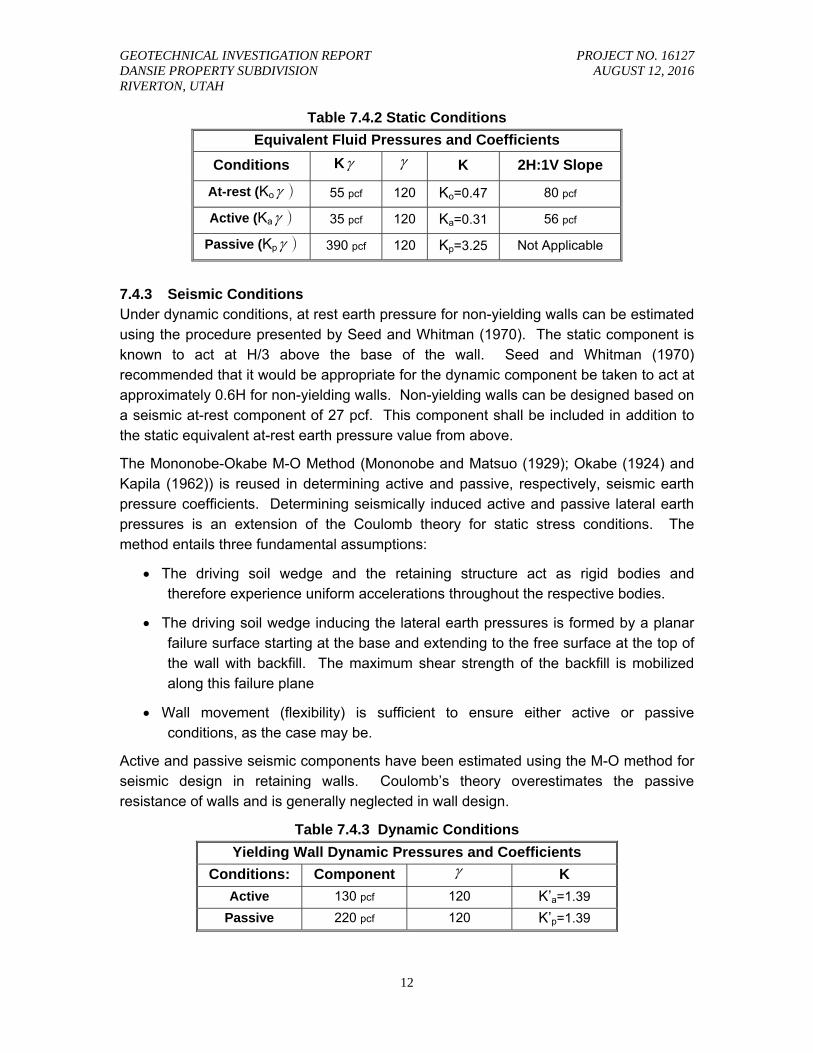
7.4.3 Seismic Conditions Under dynamic conditions, at rest earth pressure for non-yielding walls can be estimated using the procedure presented by Seed and Whitman (1970). The static component is known to act at H/3 above the base of the wall. Seed and Whitman (1970) recommended that it would be appropriate for the dynamic component be taken to act at approximately 0.6H for non-yielding walls. Non-yielding walls can be designed based on a seismic at-rest component of 27 pcf. This component shall be included in addition to the static equivalent at-rest earth pressure value from above.
The Mononobe-Okabe M-O Method (Mononobe and Matsuo (1929); Okabe (1924) and Kapila (1962)) is reused in determining active and passive, respectively, seismic earth pressure coefficients. Determining seismically induced active and passive lateral earth pressures is an extension of the Coulomb theory for static stress conditions. The method entails three fundamental assumptions:
The driving soil wedge and the retaining structure act as rigid bodies and therefore experience uniform accelerations throughout the respective bodies.
The driving soil wedge inducing the lateral earth pressures is formed by a planar failure surface starting at the base and extending to the free surface at the top of the wall with backfill. The maximum shear strength of the backfill is mobilized along this failure plane
Wall movement (flexibility) is sufficient to ensure either active or passive conditions, as the case may be.
Active and passive seismic components have been estimated using the M-O method for seismic design in retaining walls. Coulomb’s theory overestimates the passive resistance of walls and is generally neglected in wall design.
Table 7.4.3 Dynamic Conditions
Yielding Wall Dynamic Pressures and Coefficients
Conditions: Component K
Active 130 pcf 120 K’a=1.39
Passive 220 pcf 120 K’p=1.39
GEOTECHNICAL INVESTIGATION REPORT PROJECT NO. 16127 DANSIE PROPERTY SUBDIVISION AUGUST 12, 2016 RIVERTON, UTAH
13
The active seismic component shall be included in addition to the static equivalent active pressure value and, if relied upon, the passive seismic component shall be included as a reduction in the static passive resistance value.
During backfill placement and compaction below grade or behind retaining walls, the contractor shall use caution. Retaining walls can experience excessive build up of lateral pressures when backfill is over-compacted. We recommend using manual compaction practices (jumping jack, etc.). Avoid unnecessary large equipment or heavy items from being placed or operated within 5 feet of any un-braced concrete foundation or basement wall. Backfill material should meet IBC 2012 requirements and should not have aggregate greater than 3 inches in size.
7.5 Concrete Slabs on Grade Floor slabs are to be entirely supported on either suitable firm native soils or on imported structural fill placed which shall be compacted to 95% of the modified proctor (maximum dry density as determined by the ASTM D 1557 method of compaction) extending to the undisturbed native soils. It is recommended that areas immediately below any exposed concrete, i.e., driveway, sidewalks and patios, be placed with six (6) inches coarse aggregate base to distribute floor loads and provide proper drainage. Floor slabs to receive tile flooring shall have a minimum of four (4) inches of coarse aggregate base placed immediately below slabs. Floor slabs shall have adequate number of joints set by the structural engineer to reduce cracking resulting from any differential movements and shrinkage.
7.6 Seismic Information
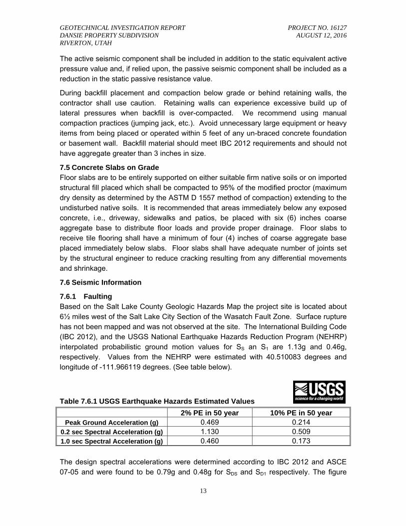
7.6.1 Faulting Based on the Salt Lake County Geologic Hazards Map the project site is located about 6½ miles west of the Salt Lake City Section of the Wasatch Fault Zone. Surface rupture has not been mapped and was not observed at the site. The International Building Code (IBC 2012), and the USGS National Earthquake Hazards Reduction Program (NEHRP) interpolated probabilistic ground motion values for SS an S1 are 1.13g and 0.46g, respectively. Values from the NEHRP were estimated with 40.510083 degrees and longitude of -111.966119 degrees. (See table below).
Table 7.6.1 USGS Earthquake Hazards Estimated Values
2% PE in 50 year 10% PE in 50 year Peak Ground Acceleration (g) 0.469 0.214
0.2 sec Spectral Acceleration (g) 1.130 0.509 1.0 sec Spectral Acceleration (g) 0.460 0.173
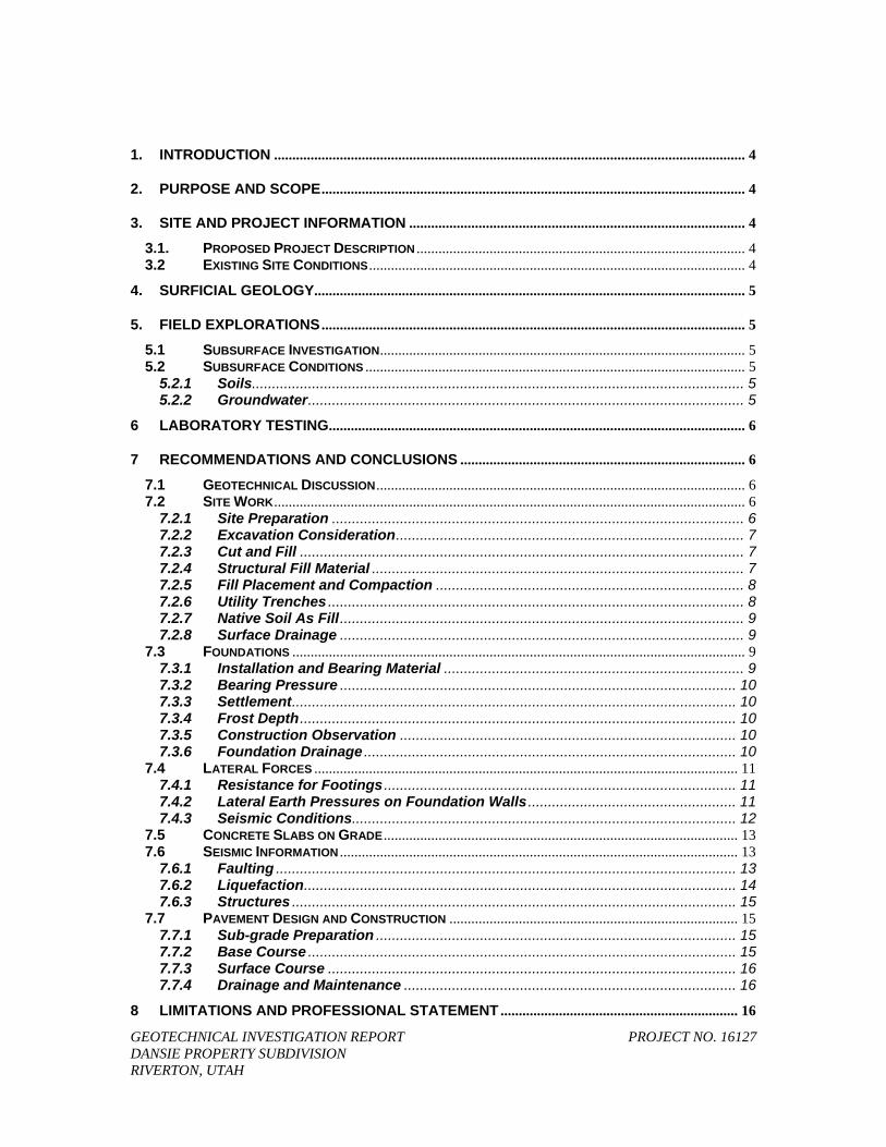
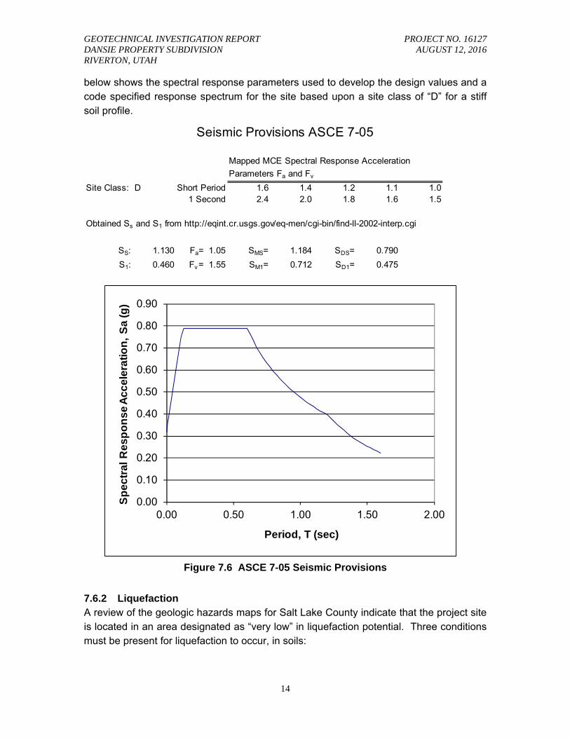
The design spectral accelerations were determined according to IBC 2012 and ASCE 07-05 and were found to be 0.79g and 0.48g for SDS and SD1 respectively. The figure
GEOTECHNICAL INVESTIGATION REPORT PROJECT NO. 16127 DANSIE PROPERTY SUBDIVISION AUGUST 12, 2016 RIVERTON, UTAH
14
below shows the spectral response parameters used to develop the design values and a code specified response spectrum for the site based upon a site class of “D” for a stiff soil profile.
Site Class: D 1.6 1.4 1.2 1.1 1.02.4 2.0 1.8 1.6 1.5
SS: 1.130 Fa= 1.05 SMS= 1.184 SDS= 0.790
S1: 0.460 Fv= 1.55 SM1= 0.712 SD1= 0.475
Obtained Ss and S1 from http://eqint.cr.usgs.gov/eq-men/cgi-bin/find-ll-2002-interp.cgi
Seismic Provisions ASCE 7-05
Short Period1 Second
Mapped MCE Spectral Response Acceleration
Parameters Fa and Fv
0.00
0.10
0.20
0.30
0.40
0.50
0.60
0.70
0.80
0.90
0.00 0.50 1.00 1.50 2.00
Sp
ec
tra
l R
es
po
ns
e A
cc
ele
rati
on
, S
a (
g)
Period, T (sec)
Figure 7.6 ASCE 7-05 Seismic Provisions
7.6.2 Liquefaction A review of the geologic hazards maps for Salt Lake County indicate that the project site is located in an area designated as “very low” in liquefaction potential. Three conditions must be present for liquefaction to occur, in soils:
GEOTECHNICAL INVESTIGATION REPORT PROJECT NO. 16127 DANSIE PROPERTY SUBDIVISION AUGUST 12, 2016 RIVERTON, UTAH
15
The soil must be susceptible to liquefaction, i.e., granular layers with less than fifteen percent fines, existing below the groundwater table.
The soil must be in a loose state.
Ground shaking strong enough to cause liquefaction.
Test Pits were excavated to depths of about 13 feet below existing ground surface. Groundwater was not encountered in any of the test pits. Based on our subsurface investigation, the subsurface profile encountered cohesive soils underlain by cohesive soils. Based on the subsurface soils encountered in the upper 13 feet, the soils are not likely to liquefy during a seismic event.
7.6.3 Structures Structures are to be designed for lateral loading as defined in the International Building Code. The site location has a design spectral response acceleration of 0.79g for short periods (SDS) and 0.48g for a one second period (SD1). Lateral loading is to be the greater of seismic loads or wind loads.
7.7 Pavement Design and Construction A pavement design has been prepared for the anticipated roadway. On-site soil characteristics from the test pit samples collected were used in determining soil strength. The pavement design assumptions consist of traffic of about 50,000 Equivalent Single Axle Loads (ESALs) with a twenty (20) year design period of 80% reliability, a California Bearing Ratio CBR of 3 (assumed), standard deviation of 0.35, and Initial and Terminal serviceability of 4.2 and 2.5, respectively. The following sections will provide preparation and design for pavement based on AASHTO design procedures.
7.7.1 Sub-grade Preparation All topsoil, or any soil containing organic materials, must be removed from locations where structural loads will be applied. To evaluate its stability, the sub-grade shall be "proof rolled" with a loaded dump truck or tested with a nuclear density gauge. Any unsuitable soils shall be removed and replaced with structural fill according to Section 7.2.4. Any areas of fill or disturbed areas shall be compacted to 95% of the ASTM D1557 modified proctor. A geotechnical engineer shall observe unsuitable sub-grade remediation.
7.7.2 Base Course A minimum of eight (8) inches of untreated base course is required for the roadway. The base course shall comply with a ¾-inch mix per UDOT Standard Specifications, Section 02721, “Untreated Base Course.”
GEOTECHNICAL INVESTIGATION REPORT PROJECT NO. 16127 DANSIE PROPERTY SUBDIVISION AUGUST 12, 2016 RIVERTON, UTAH
16
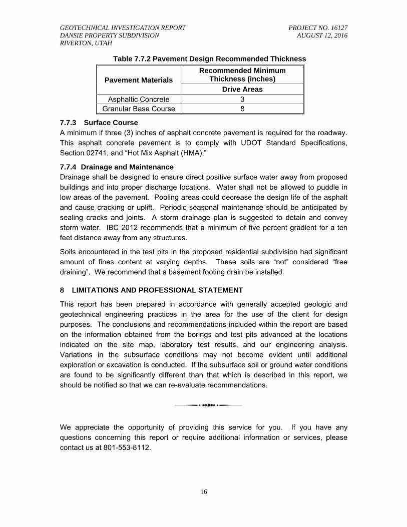
Table 7.7.2 Pavement Design Recommended Thickness
Pavement Materials Recommended Minimum
Thickness (inches)
Drive Areas Asphaltic Concrete 3
Granular Base Course 8
7.7.3 Surface Course A minimum if three (3) inches of asphalt concrete pavement is required for the roadway. This asphalt concrete pavement is to comply with UDOT Standard Specifications, Section 02741, and “Hot Mix Asphalt (HMA).”
7.7.4 Drainage and Maintenance Drainage shall be designed to ensure direct positive surface water away from proposed buildings and into proper discharge locations. Water shall not be allowed to puddle in low areas of the pavement. Pooling areas could decrease the design life of the asphalt and cause cracking or uplift. Periodic seasonal maintenance should be anticipated by sealing cracks and joints. A storm drainage plan is suggested to detain and convey storm water. IBC 2012 recommends that a minimum of five percent gradient for a ten feet distance away from any structures.
Soils encountered in the test pits in the proposed residential subdivision had significant amount of fines content at varying depths. These soils are “not” considered “free draining”. We recommend that a basement footing drain be installed.
8 LIMITATIONS AND PROFESSIONAL STATEMENT
This report has been prepared in accordance with generally accepted geologic and geotechnical engineering practices in the area for the use of the client for design purposes. The conclusions and recommendations included within the report are based on the information obtained from the borings and test pits advanced at the locations indicated on the site map, laboratory test results, and our engineering analysis. Variations in the subsurface conditions may not become evident until additional exploration or excavation is conducted. If the subsurface soil or ground water conditions are found to be significantly different than that which is described in this report, we should be notified so that we can re-evaluate recommendations.
We appreciate the opportunity of providing this service for you. If you have any questions concerning this report or require additional information or services, please contact us at 801-553-8112.

GEOTECHNICAL INVESTIGATION REPORT PROJECT NO. 16127 DANSIE PROPERTY SUBDIVISION AUGUST 12, 2016 RIVERTON, UTAH
18
APPENDIX
Project:
Dansie Property Subdivision 13400 South Hawthorne Way Riverton, Utah
Project No: 16127
Date: August 2016
Drawn By: CPB
Figure: A-1
VICINITY MAP
SITE
GB1
GB2
GB3
GB4
GB5
4552.0
4542.0
MC = 8%
MC = 6%LL = 27PL = 17
Fines = 61% CL
2.0
12.0
TOPSOIL: Lean Clay with Sand, moist, light brown, with roots and vegetation.
LEAN CLAY WITH SAND: moist, light brown.
-- Sandy Lean Clay, moist, light brown.
-- with Gravel.
Bottom of test pit at 12.0 feet.
NOTES
GROUND ELEVATION 4554 ft
LOGGED BY JGW
EXCAVATION METHOD Test Pit
EXCAVATION CONTRACTOR Gary Lancester GROUND WATER LEVELS:
CHECKED BY CPB
DATE STARTED 7/22/16 COMPLETED 7/22/16
AT TIME OF EXCAVATION ---
AT END OF EXCAVATION ---
AFTER EXCAVATION ---
TEST PIT SIZE 60 inches
SA
MP
LE
TY
PE
NU
MB
ER
DE
PT
H(f
t)
0.0
2.5
5.0
7.5
10.0
PAGE 1 OF 1TEST PIT NUMBER TP-1
CLIENT Lovell Development
PROJECT NUMBER 16127
PROJECT NAME Dansie Property Subdivision
PROJECT LOCATION Riverton, Utah
GE
NE
RA
L B
H /
TP
/ W
ELL
- G
INT
ST
D U
S L
AB
.GD
T -
8/9
/16
11:5
5 -
G:\D
AT
A\1
6127
LO
VE
LL D
AN
SIE
\SO
ILS
\TE
ST
PIT
LO
GS
\161
27 D
AN
SIE
PR
OP
ER
TY
SU
BD
IVIS
ION
.GP
J
Wilding Engineering, Inc
TESTS
U.S
.C.S
.
GR
AP
HIC
LOG
MATERIAL DESCRIPTION
GB1
GB2
SH3
GB4
GB5
GB6
4559.0
4549.0
MC = 26%LL = 27PL = 17
Fines = 85%
MC = 26%
MC = 24%
CL
2.0
12.0
TOPSOIL: Lean Clay with Sand, moist, dark brown, with roots and vegetation.
LEAN CLAY: moist, light brown.
-- with Sand.
-- moderate brown.
-- olive green.
Bottom of test pit at 12.0 feet.
NOTES
GROUND ELEVATION 4561 ft
LOGGED BY JGW
EXCAVATION METHOD Test Pit
EXCAVATION CONTRACTOR Gary Lancester GROUND WATER LEVELS:
CHECKED BY CPB
DATE STARTED 7/22/16 COMPLETED 7/22/16
AT TIME OF EXCAVATION ---
AT END OF EXCAVATION ---
AFTER EXCAVATION ---
TEST PIT SIZE 60 inches
SA
MP
LE
TY
PE
NU
MB
ER
DE
PT
H(f
t)
0.0
2.5
5.0
7.5
10.0
PAGE 1 OF 1TEST PIT NUMBER TP-2
CLIENT Lovell Development
PROJECT NUMBER 16127
PROJECT NAME Dansie Property Subdivision
PROJECT LOCATION Riverton, Utah
GE
NE
RA
L B
H /
TP
/ W
ELL
- G
INT
ST
D U
S L
AB
.GD
T -
8/9
/16
11:5
5 -
G:\D
AT
A\1
6127
LO
VE
LL D
AN
SIE
\SO
ILS
\TE
ST
PIT
LO
GS
\161
27 D
AN
SIE
PR
OP
ER
TY
SU
BD
IVIS
ION
.GP
J
Wilding Engineering, Inc
TESTS
U.S
.C.S
.
GR
AP
HIC
LOG
MATERIAL DESCRIPTION
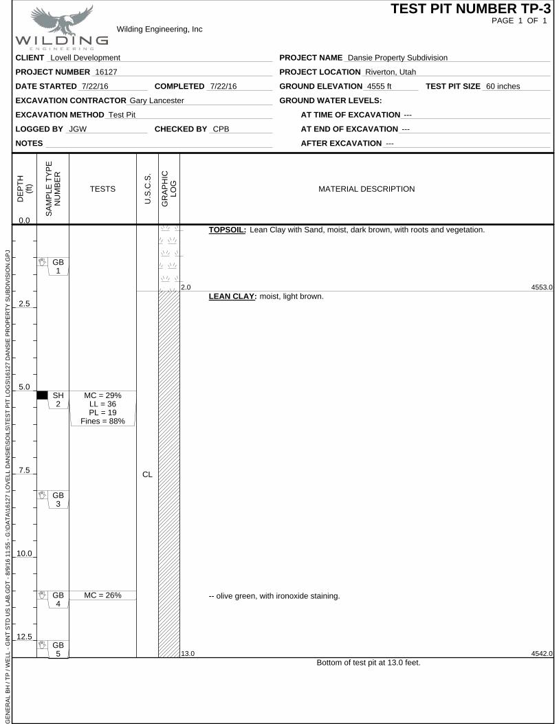
GB1
SH2
GB3
GB4
GB5
4553.0
4542.0
MC = 29%LL = 36PL = 19
Fines = 88%
MC = 26%
CL
2.0
13.0
TOPSOIL: Lean Clay with Sand, moist, dark brown, with roots and vegetation.
LEAN CLAY: moist, light brown.
-- olive green, with ironoxide staining.
Bottom of test pit at 13.0 feet.
NOTES
GROUND ELEVATION 4555 ft
LOGGED BY JGW
EXCAVATION METHOD Test Pit
EXCAVATION CONTRACTOR Gary Lancester GROUND WATER LEVELS:
CHECKED BY CPB
DATE STARTED 7/22/16 COMPLETED 7/22/16
AT TIME OF EXCAVATION ---
AT END OF EXCAVATION ---
AFTER EXCAVATION ---
TEST PIT SIZE 60 inches
SA
MP
LE
TY
PE
NU
MB
ER
DE
PT
H(f
t)
0.0
2.5
5.0
7.5
10.0
12.5
PAGE 1 OF 1TEST PIT NUMBER TP-3
CLIENT Lovell Development
PROJECT NUMBER 16127
PROJECT NAME Dansie Property Subdivision
PROJECT LOCATION Riverton, Utah
GE
NE
RA
L B
H /
TP
/ W
ELL
- G
INT
ST
D U
S L
AB
.GD
T -
8/9
/16
11:5
5 -
G:\D
AT
A\1
6127
LO
VE
LL D
AN
SIE
\SO
ILS
\TE
ST
PIT
LO
GS
\161
27 D
AN
SIE
PR
OP
ER
TY
SU
BD
IVIS
ION
.GP
J
Wilding Engineering, Inc
TESTS
U.S
.C.S
.
GR
AP
HIC
LOG
MATERIAL DESCRIPTION
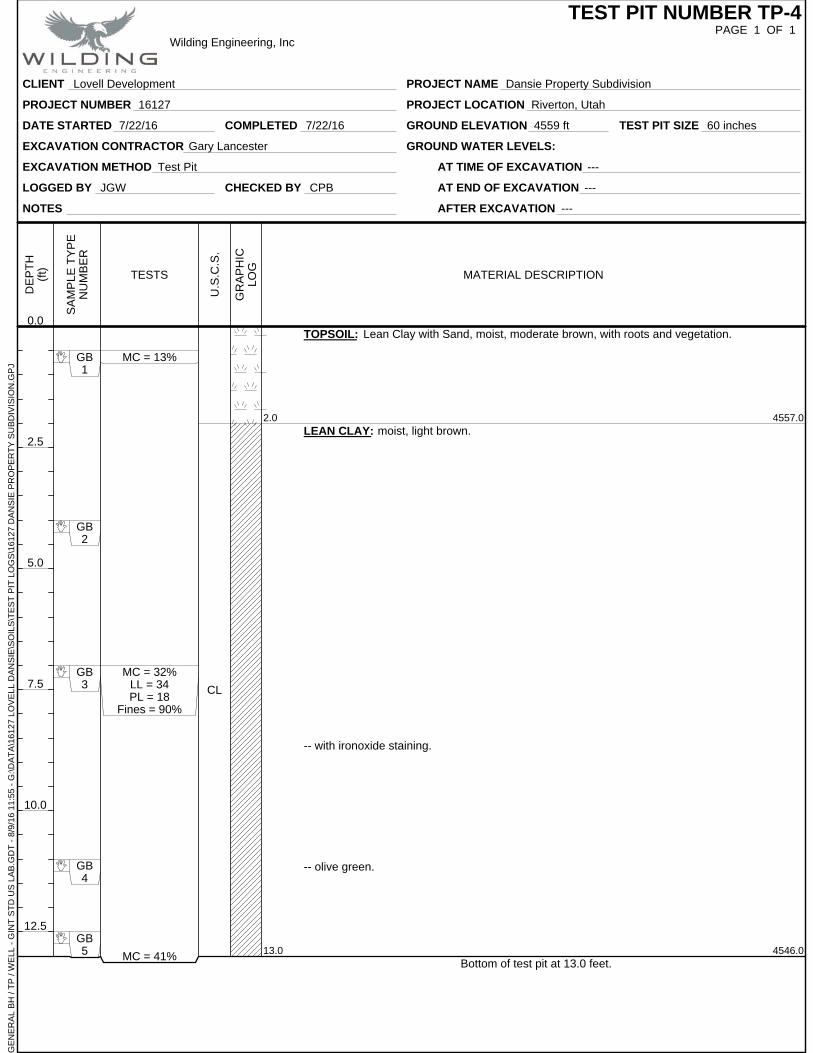
GB1
GB2
GB3
GB4
GB5
4557.0
4546.0
MC = 13%
MC = 32%LL = 34PL = 18
Fines = 90%
MC = 41%
CL
2.0
13.0
TOPSOIL: Lean Clay with Sand, moist, moderate brown, with roots and vegetation.
LEAN CLAY: moist, light brown.
-- with ironoxide staining.
-- olive green.
Bottom of test pit at 13.0 feet.
NOTES
GROUND ELEVATION 4559 ft
LOGGED BY JGW
EXCAVATION METHOD Test Pit
EXCAVATION CONTRACTOR Gary Lancester GROUND WATER LEVELS:
CHECKED BY CPB
DATE STARTED 7/22/16 COMPLETED 7/22/16
AT TIME OF EXCAVATION ---
AT END OF EXCAVATION ---
AFTER EXCAVATION ---
TEST PIT SIZE 60 inches
SA
MP
LE
TY
PE
NU
MB
ER
DE
PT
H(f
t)
0.0
2.5
5.0
7.5
10.0
12.5
PAGE 1 OF 1TEST PIT NUMBER TP-4
CLIENT Lovell Development
PROJECT NUMBER 16127
PROJECT NAME Dansie Property Subdivision
PROJECT LOCATION Riverton, Utah
GE
NE
RA
L B
H /
TP
/ W
ELL
- G
INT
ST
D U
S L
AB
.GD
T -
8/9
/16
11:5
5 -
G:\D
AT
A\1
6127
LO
VE
LL D
AN
SIE
\SO
ILS
\TE
ST
PIT
LO
GS
\161
27 D
AN
SIE
PR
OP
ER
TY
SU
BD
IVIS
ION
.GP
J
Wilding Engineering, Inc
TESTS
U.S
.C.S
.
GR
AP
HIC
LOG
MATERIAL DESCRIPTION
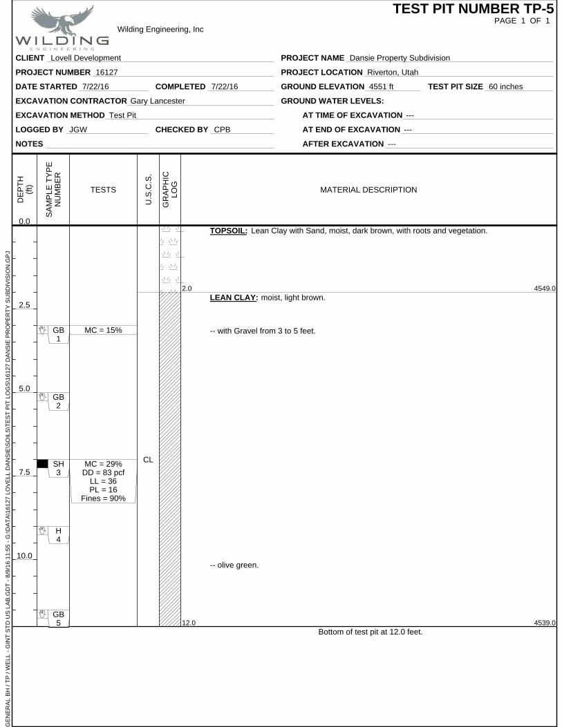
GB1
GB2
SH3
H4
GB5
4549.0
4539.0
MC = 15%
MC = 29%DD = 83 pcf
LL = 36PL = 16
Fines = 90%
CL
2.0
12.0
TOPSOIL: Lean Clay with Sand, moist, dark brown, with roots and vegetation.
LEAN CLAY: moist, light brown.
-- with Gravel from 3 to 5 feet.
-- olive green.
Bottom of test pit at 12.0 feet.
NOTES
GROUND ELEVATION 4551 ft
LOGGED BY JGW
EXCAVATION METHOD Test Pit
EXCAVATION CONTRACTOR Gary Lancester GROUND WATER LEVELS:
CHECKED BY CPB
DATE STARTED 7/22/16 COMPLETED 7/22/16
AT TIME OF EXCAVATION ---
AT END OF EXCAVATION ---
AFTER EXCAVATION ---
TEST PIT SIZE 60 inches
SA
MP
LE
TY
PE
NU
MB
ER
DE
PT
H(f
t)
0.0
2.5
5.0
7.5
10.0
PAGE 1 OF 1TEST PIT NUMBER TP-5
CLIENT Lovell Development
PROJECT NUMBER 16127
PROJECT NAME Dansie Property Subdivision
PROJECT LOCATION Riverton, Utah
GE
NE
RA
L B
H /
TP
/ W
ELL
- G
INT
ST
D U
S L
AB
.GD
T -
8/9
/16
11:5
5 -
G:\D
AT
A\1
6127
LO
VE
LL D
AN
SIE
\SO
ILS
\TE
ST
PIT
LO
GS
\161
27 D
AN
SIE
PR
OP
ER
TY
SU
BD
IVIS
ION
.GP
J
Wilding Engineering, Inc
TESTS
U.S
.C.S
.
GR
AP
HIC
LOG
MATERIAL DESCRIPTION
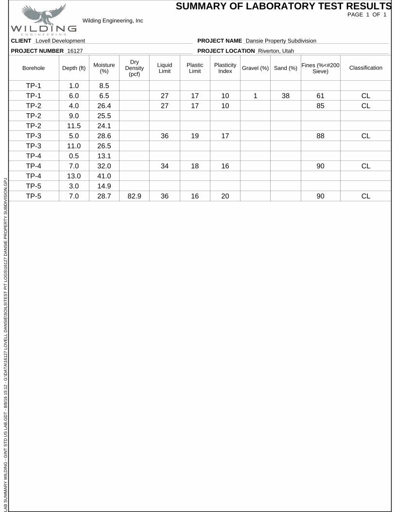
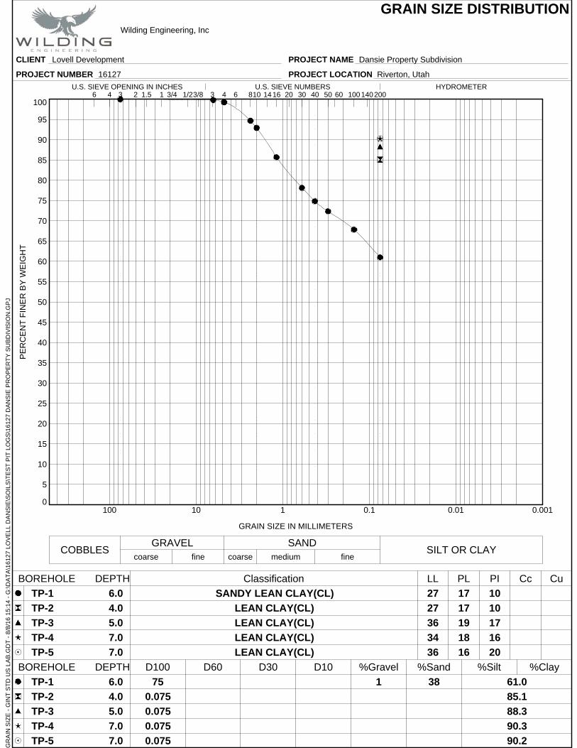
TP-1 1.0 8.5
TP-1 6.0 6.5 27 17 10 1 38 61 CL
TP-2 4.0 26.4 27 17 10 85 CL
TP-2 9.0 25.5
TP-2 11.5 24.1
TP-3 5.0 28.6 36 19 17 88 CL
TP-3 11.0 26.5
TP-4 0.5 13.1
TP-4 7.0 32.0 34 18 16 90 CL
TP-4 13.0 41.0
TP-5 3.0 14.9
TP-5 7.0 28.7 82.9 36 16 20 90 CL
PAGE 1 OF 1
Borehole ClassificationFines (%<#200Sieve)
Sand (%)Gravel (%)Depth (ft) PlasticLimit
LiquidLimit
DryDensity
(pcf)
PlasticityIndex
Moisture(%)
SUMMARY OF LABORATORY TEST RESULTS
CLIENT Lovell Development
PROJECT NUMBER 16127
PROJECT NAME Dansie Property Subdivision
PROJECT LOCATION Riverton, Utah
LAB
SU
MM
AR
Y W
ILD
ING
- G
INT
ST
D U
S L
AB
.GD
T -
8/8
/16
15:1
2 -
G:\D
AT
A\1
6127
LO
VE
LL D
AN
SIE
\SO
ILS
\TE
ST
PIT
LO
GS
\161
27 D
AN
SIE
PR
OP
ER
TY
SU
BD
IVIS
ION
.GP
J
Wilding Engineering, Inc
0
5
10
15
20
25
30
35
40
45
50
55
60
65
70
75
80
85
90
95
100
0.0010.010.1110100
6 601.5 8 143/4 3/8
6.0
4.0
5.0
7.0
7.0
PE
RC
EN
T F
INE
R B
Y W
EIG
HT
COBBLESGRAVEL
61.0
85.1
88.3
90.3
90.2
75
0.075
0.075
0.075
0.075
SAND
GRAIN SIZE IN MILLIMETERS
coarse fine
38
SANDY LEAN CLAY(CL)
LEAN CLAY(CL)
LEAN CLAY(CL)
LEAN CLAY(CL)
LEAN CLAY(CL)
Classification
D100 D60 D30 D10 %Gravel
TP-1
TP-2
TP-3
TP-4
TP-5
coarseSILT OR CLAY
finemedium
6.0
4.0
5.0
7.0
7.0
%Sand %Silt %Clay
PI Cc
17
17
19
18
16
27
27
36
34
36
CuLL PL
10
10
17
16
20
GRAIN SIZE DISTRIBUTION
3 100
TP-1
TP-2
TP-3
TP-4
TP-5
24 16 30
BOREHOLE DEPTH
1 2006 10 501/2HYDROMETERU.S. SIEVE OPENING IN INCHES U.S. SIEVE NUMBERS
1403 4 20 40
1
BOREHOLE DEPTH
CLIENT Lovell Development
PROJECT NUMBER 16127
PROJECT NAME Dansie Property Subdivision
PROJECT LOCATION Riverton, Utah
GR
AIN
SIZ
E -
GIN
T S
TD
US
LA
B.G
DT
- 8
/8/1
6 15
:14
- G
:\DA
TA
\161
27 L
OV
ELL
DA
NS
IE\S
OIL
S\T
ES
T P
IT L
OG
S\1
6127
DA
NS
IE P
RO
PE
RT
Y S
UB
DIV
ISIO
N.G
PJ
Wilding Engineering, Inc
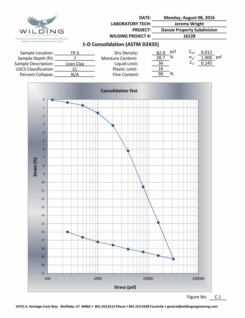
pcf
Moisture Content: % psf
Plastic Limit:Fine Content: %N/A 90Percent Collapse:
Liquid Limit: 0.145
Figure No. C‐1
WILDING PROJECT #: 16128
1‐D Consolidation (ASTM D2435)
Sample Location:Sample Depth (ft):
0.0131,900
Sample Description: 3616
Cre:
Cc:p':
USCS Classification:
82.928.7
Dry Density:TP‐57
Lean ClayCL
DATE: Monday, August 08, 2016
LABORATORY TECH: Jeremy Wright
PROJECT: Dansie Property Subdivision
0
1
2
3
4
5
6
7
8
9
10
11
12
13
14
15
16
17
18
19
20
21
100 1000 10000 100000
Strain (%)
Stress (psf)
Consolidation Test
14721 S. Heritage Crest Way Bluffdale, UT 84065 • 801.553.8112 Phone • 801.553.9108 Facsimile • [email protected]