
AKH-Hauptantriebsmotoren 2-polig, FU-Betrieb (reduziertes ...

Explosionsgeschützte Steckvorrichtungen 16 A, 3-polig, 4-polig, 5-polig, GHG 511
Explosion protected plug and socket system 16 A, 3-pole, 4-pole, 5-pole, GHG 511
Fiches et prises de 16 A, à 3 pôles, 4 pôles, 5 pôles, pour atmosphères explosives, GHG 511
BetriebsanleitungOperating instructionsMode d’emploi
GHG 510 7001 P0001 D/GB/F (Q)
CROUSE-HINDSSERIES

2
Explosionsgeschützte Steckvorrichtungen 16 A, 3-polig, 4-polig, 5-polig, GHG 511
Explosion protected plug and socket system 16 A, 3-pole, 4-pole, 5-pole, GHG 511
Fiches et prises de 16 A, à 3 pôles, 4 pôles, 5 pôles, pour atmosphères explosives, GHG 511
InhaltInhalt:. ................................................................ 2
1 Technische Angaben ............................ 3, 4
1.1 Hilfskontakt .............................................. 4
2.1 Sicherheitshinweise .................................. 5
3 Normenkonformität .................................. 5
4 Verwendungsbereich................................ 5
5 Verwendung/Eigenschaften...................... 5
6 Installation ................................................ 6
6.1 Montage .................................................. 6
6.2 Öffnen des Gerätes / Elektrischer Anschluss ............................. 6
6.3 Kabel- und Leitungs einführungen (KLE); Verschluss Stopfen .................................. 6
6.3.1 Steckdosen .............................................. 6
6.3.2 Stecker/Kupplung .................................... 7
6.4 Schließen des Gerätes ............................. 7
6.5 Inbetriebnahme ........................................ 7
7 Instandhaltung/Wartung ........................... 7
8 Reparatur/Instandsetzung/Änderungen ... 7
9 Entsorgung / Wiederverwertung .................................... 7
Schaltschema ....................................... 18
Kodierung ............................................. 19
Maßbilder ....................................... 20 - 21
Konformitätserklärung separat beigelegt.
ContentsContents:. .......................................................... 2
1 Technical data ...................................... 8, 9
1.1 Auxiliary contact ....................................... 9
2.1 Safety instructions .................................. 10
3 Conformity with standards ..................... 10
4 Field of application ................................. 10
5 Use/Properties ....................................... 10
6 Installation .............................................. 11
6.1 Mounting................................................ 11
6.2 Opening the device/ Electrical connection .............................. 11
6.3 Cable entries (KLE); blanking plugs ........................................ 11
6.3.1 Socket ................................................... 11
6.3.2 Plug/coupler .......................................... 12
6.4 Closing the device .................................. 12
6.5 Taking into operation .............................. 12
7 Maintenance/Servicing ........................... 12
8 Repair/Overhaul/ Modifications .......................................... 12
9 Disposal/Recycling ................................. 12
Switching operation ............................... 18
Coding ................................................... 19
Dimensional drawings ..................... 20 - 21
Declaration of conformity, enclosed separately.
Contenu Contenu:. ........................................................... 2
1 Caractéristiques techniques ............. 13, 14
1.1 Contact auxiliaire .................................... 14
2.1 Consignes de sécurité ......................... 153 Conformité avec les normes ............................ 15
4 Domaine d’utilisation .............................. 15
5 Utilisation/Propriétés .............................. 15
6 Installation .............................................. 16
6.1 Montage ................................................ 16
6.2 Ouverture du dispositif/ Raccordement électrique ............................................... 16
6.3 Entrées de câble (KLE); bouchons de fermeture .......................... 16
6.3.1 Prise ...................................................... 16
6.3.2 Fiche / prolongateur ............................... 17
6.4 Fermeture du dispositif ........................... 17
6.5 Mise en service ...................................... 17
7 Maintien/Entretien .................................. 17
8 Réparation / Remise en état ................... 17
9 Évacuation des déchets/ Recyclage .............................................. 17
Mécanisme de commutation .................. 18
Codage .................................................. 19
Plans cotés ..................................... 20 - 21
Déclaration de conformité, jointe séparément.

3
Explosionsgeschützte Steckvorrichtungen 16 A, 3-polig, 4-polig, 5-polig, GHG 511
1 Technische Angaben
ATEX EU-Baumusterprüfbescheinigung / IECEx Konformitätsbescheinigung:Wandsteckdose GHG 511 4. BVS 17 ATEX E 053 X IECEx BVS 17.0045 XStecker GHG 511 7. BVS 17 ATEX E 053 X IECEx BVS 17.0045 XKupplung GHG 511 3. BVS 17 ATEX E 053 X IECEx BVS 17.0045 XFlanschsteckdose GHG 511 8. BVS 15 ATEX E 101 U IECEx BVS 15.0088 UStecker GHG 543 2. PTB 99 ATEX 1039 IECEx BVS 04.0002Stecker GHG 531 7. PTB 99 ATEX 1039 IECEx BVS 04.0002Gerätekennzeichnung nach 2014/34/EU und der Normenreihe EN 60079:
D II 2 G Ex db eb [ia] IIC / IIB / IIB+H2 T6 / T5 GbD II 2 D Ex tb IIIC T80 °C Db
Flanschsteckdose GHG 511 8 D II 2 G Ex db eb IIC / IIB / IIB+H2 Gb
D II 2 D Ex tb IIIC / IIIB DbGerätekennzeichnung der Normenreihe IEC 60079:
Ex db eb [ia] IIC / IIB / IIB+H2 T6 / T5 GbEx tb IIIC T80 °C Db
Bemessungsspannung:GHG 511 - 3-polig bis 415 V, 50/60 Hz; max 400 HzGHG 511 - 4-polig bis 690 V, 50/60 Hz; max 400 HzGHG 511 - 5-polig bis 690 V, 50/60 Hz; max 400 HzStecker GHG 543 2. bis 250 V, 50/60 HzStecker GHG 531 7. bis 690 V, 50/60 Hz(Sonder - Spannungen und -Uhrzeiten sind auf Anfrage möglich)
Gasgruppe Umgebungstemperaturbereich
IIB IIB+H2 IIC XATEX - IEC Geschützter Einbauort
wählen. Maximale Schlagenergie 4 JTyp: maximaler Bemessungsstrom
Wandsteckdose GHG 51.4...R.... / Flanschsteckdose GHG 51.8...R.... / 3p (Standard Temperaturbereich).. 16 A - - -45 °C ... +55 °C
- 16 A - -30 °C ... +55 °C- - 16 A -20 °C ... +55 °C
Wandsteckdose GHG 51.4...R.1.. / Flanschsteckdose GHG 51.8...R.1.. / 3/4/5p (Erweiterter Temperaturbereich)
16 A 16 A - -55 °C ... +45 °C10 A 10 A - -55 °C ... +55 °C- - 16 A -20 °C ... +45 °C- - 10 A -20 °C ... +55 °C
Wandsteckdose GHG 51.4...R.... / Flanschsteckdose 51.8...R.... / 4/5p (Standard Temperaturbereich)16 A 16 A - -55 °C ... +55 °C- - 16 A -20 °C ... +55 °C
Kupplung GHG 51.3...R.... 16 A 16 A 16 A -20 °C ... +55 °C
Stecker GHG 51.7...R.... ( min. 2,5 mm²)16 A 16 A 16 A -40 °C ... +45 °C -55 °C ... +45 °C
Stecker GHG 51.7...R.... ( min. 4,0 mm²)16 A 16 A 16 A -40 °C ... +55 °C -55 °C ... +55 °C
Stecker GHG 51.7...R.... ( min. 2,5 mm²)10 A 10 A 10 A -40 °C ... +55 °C -55 °C ... +55 °C
Stecker GHG 51.7...R.... ( 1,5 - 2,5 mm²) ( 4,0 mm²)16 A 16 A 16 A -20 °C ... +40 °C -55 °C ... +40 °C
Stecker GHG 543 2. / GHG 531 7.16 A 16 A 16 A -20 °C ... +40 °C
(Abweichende Temperaturen sind bei Sonderversionen möglich.)Max. Vorsicherung: GHG 511 GHG 543/531ohne therm. Schutz 20 A 16 Amit therm. Schutz 35 A gG 32 A gG
Schaltvermögen AC 3 3-polig: 250 V/16 A
Schaltvermögen AC 3 4-polig: 400 V/16 ASchaltvermögen AC 3 5-polig: 500 V/16 ASchutzart nach EN/IEC 60529 IP 66 (Listenausführung)(1)
(1)bei geschlossenem und gesichertem Klappdeckel sowie ordnungsgemäß gesteckten Kombinationen. Achtung! Die IP- Schutzart der gesteckten Stecker GHG 543/531 mit Steckdosen und Kupplungen der Baureihe GHG 511 reduziert sich auf die Mindeststschutzart IP 54.
Schutzklasse nach EN/IEC 61140: I - mit Metallflansch oder Metall KLEs II - wird von den Geräten erfüllt
D

4
DExplosionsgeschützte Steckvorrichtungen 16 A, 3-polig, 4-polig, 5-polig, GHG 511
Leitungseinführung: (Listenausführung)Wandsteckdose 2 x M25 1 x M25 + 1 x SchraubverschlussGeeignete Leitungen und Prüfdrehmomente der Druckschraube für KLE (Ømm/Nm) (Standard KLE Kunststoff GHG960):
M20 M25 M32
Dichtung 1+2+3 1 2 3 min. max. (2)
5,5/1,5 7,0/1,0
8,0/1,5 10,0/2,0
Dichtung 1+2 1 2 3 min. max. (2)
7,0/1,5 9,0/1,4
10,0/2,3 13,0/2,6
14,0/3,0 17,0/4,0
Dichtung 1 1 2 3 min. max. (2)
9,5/1,0 13,0/1,7
13,5/1,3 17,5/2,3
17,5/1,5 21,0/1,3
Prüfdrehmomente Einschraubgewinde (Nm) 2,7 3,0 5,0
(2) Die Prüfungen der Klemmbereiche und Prüfdrehmomente wurden mit Metalldornen durchgeführt. Bei der Verwendung von Leitungen mit unterschiedlichen Fertigungstoleranzen und Materialeigenschaften kann der Klemmbereich variieren. Bitte verwenden Sie im Zwischenbereich eine geeignete Kombination aus Dichtungen, so dass bei zukünftigen Wartungsarbeiten an der KLE die Hutmutter nachgezogen werden kann.
Geeignete Leitungen:Anschlussquerschnitt / Klemmbereich:
Abisolierlänge der Adern
Wand-/Flaschschteckdose 2 x 1,5 - 4,0 mm2 10 mmStecker 3-polig Ø 8 - 18 mm 1 x 1,5 - 4,0 mm² (3) (4) 9 mmKupplung 3-polig Ø 8 - 19 mm 1 x 1,5 - 4,0 mm² (3) 10 mmStecker / Kupplung 4-polig Ø 8 - 21 mm 1 x 1,5 - 4,0 mm² (3) (4) 9 mm / 10 mmStecker / Kupplung 5-polig Ø 12 - 21 mm 1 x 1,5 - 4,0 mm² (3) (4) 9 mm / 10 mmStecker GHG 543/531 Ø 9 - 17 mm 1 x 1,0 - 4,0 mm2 8 mm(3) 4,0 mm² nur mit Stiftkabelschuh. (4) Umgebungstemperaturbereich beachten!Prüfdrehmomente:Anschlussklemmen:. Wand-/Flaschschteckdose 2,5 Nm
Kupplung 2,5 NmStecker 1,5 Nm
Deckelschrauben 2,5 NmBefestigungsschraube Flansch 1,6 NmSelbstschneidende Schrauben Größe 4 1,6 Nm (Seite 15, Bild 3, Pos. 3)Befestigungsschraube Druckstück GHG 54 1,6 Nm
Gewicht: (Listenausführung)Wandsteckdose 3-polig GHG 511 43 ca. 1,10 kgStecker 3-polig GHG 511 73 ca. 0,27 kg / GHG 543 - ca. 0,23 kgKupplung 3-polig GHG 511 33 ca. 0,61 kgFlanschsteckdose 3-polig GHG 511 83 ca. 0,38 kgWandsteckdose 4-polig GHG 511 44 ca. 1,50 kgStecker 4-polig GHG 511 74 ca. 0,34 kg / GHG 531 - ca. 0,40 kgKupplung 4-polig GHG 511 34 ca. 0,89 kgFlanschsteckdose 4-polig GHG 511 84 ca. 0,53 kgWandsteckdose 5-polig GHG 511 45 ca. 1,55 kgStecker 5-polig GHG 511 75 ca. 0,38 kg / GHG 531 - ca. 0,41 kgKupplung 5-polig GHG 511 35 ca. 0,89 kgFlanschsteckdose 5-polig GHG 511 85 ca. 0,58 kg
1 Technische Angaben
1.1 Hilfskontakt
Hilfskontakt, Bemessungsspannung: 250 VACHilfskontakt, Bemessungsstrom: AC / 5 A DC / 0,03 A
5
2 Legende Achtung Dieses Symbol warnt vor einem möglichen Ausfall. Wird diese Warnung nicht beobachtet kann der Gesamtausfall der Vorrichtung oder des Systems oder des Betriebes erfolgen, an die es angeschlos-sen wird.
XATEX - IEC Besondere Bedingungen
Dieses Symbol weißt auf Hinweise zum sicheren Betrieb gemäß EU-Baumusterprüfbescheinigung / IECEx-Konformitätsbescheinigung hin.
2.1 SicherheitshinweiseZielgruppe: Elektrofachkräfte und geeignet qualifizierte, unterwiesene Personen gemäß den nationalen Rechtsvorschriften,
einschließlich der einschlägigen Normen für elektrische Geräte in explosionsgefährdeten Bereichen (EN/IEC 60079-14).
Die Steckvorrichtungen GHG 511 sind nicht für Zone 0 und Zone 20 geeignet. Die auf den Geräten angegebene Temperaturklasse und Zündschutzart ist zu beachten.
Umbauten oder Veränderungen an den Steckvorrichtungen sind nicht gestattet. Sie sind bestimmungsgemäß in unbeschädigtem und einwandfreiem Zustand zu betreiben.
Die Anforderungen der EN/IEC 60079-31 u.a. in Bezug auf übermäßige Staubablagerungen und Temperatur, sind vom Anwender zu beachten.
Für die Einhaltung der auf dem Typenschild des Betriebsmittels angegebenen Temperatur klasse ist die zulässige Umgebungstempe-ratur, der Anschlussquerschnitt, sowie die, maßgeblich durch die Verlust leistung bedingte Eigenerwärmung des Betriebsmittels zu beachten (Prüfkriterium für die Eigenerwärmung ist eine Überlastung um 10%).
Vor Inbetriebnahme müssen die Steckvorrichtungen entsprechend der im Abschnitt 6 genannten Anweisung geprüft werden. Die Steckvorrichtungen nur mit den zugehörigen unbeschädigten Cooper Crouse-Hinds Steckern betreiben.
Der Steckdoseneinsatz der Steckdose ist mechanisch gesichert und damit ohne Stecker nicht einschaltbar.
Stecker der Baureihe GHG 543/GHG 531 dürfen weiter in Steckdosen der Baureihe GHG 543/531 betrieben werden.
Flanschsteckdosen dürfen nur für den entsprechenden Einsatzbereich bescheinigten Schutzgehäuse oder Geräte eingesetzt werden.
Beachten Sie die nationalen Sicherheits- und Unfallverhütungsvor-schriften und die nachfolgenden Sicherheitshinweise in dieser Betriebsanleitung, die wie dieser Text in Kursivschrift gefasst sind!
3 NormenkonformitätDas Betriebsmittel entspricht den aufgeführten Normen, in der separat beigelegten Konformitätserklärung.
Verweise auf Normen und Richtlinien in dieser Betriebsanleitung beziehen sich immer auf die aktuelle Version. Zusätzliche Ergänzungen (z.B. Jahreszahlangaben) sind zu beachten.
D
4 VerwendungsbereichDie Steckvorrichtungen GHG 511 sind zum Einsatz in explosionsgefährde-ten Bereichen der Zonen 1 und 2 sowie der Zonen 21 und 22 gemäß EN/IEC 60079-10-1 und EN/IEC 60079-10-2, geeignet!
Die eingesetzten Gehäusematerialien einschließlich der außenliegenden Metallteile bestehen aus hochwertigen Werkstoffen, die einen anwen-dungsgerechten Korrosionsschutz und Chemi kalienresistenz in „normaler Industrieatmosphäre” gewährleisten:
- schlagfestes Polyamid - glasfaserverstärktes Polyester - Edelstahl AISI 316 L.
Bei einem Einsatz in extrem aggressiver Atmos phäre, können Sie zusätzliche Infor mationen über die Chemikalienbeständigkeit der eingesetzten Kunststoffe, bei Ihrer zustän digen Cooper Crouse-Hinds Niederlassung erfragen.
5 Verwendung/EigenschaftenDie Steckvorrichtungen dienen zur Strom versorgung von standortvariablen Vor-Ort- Steuerungen, elektrischen Anlagen sowie von beweglichen Maschinen und Antrieben in explosionsgefährdeten Bereichen.
Die Steckdosen für Niederspannungen sind mit einem Lastschalter ausgestattet und sind bis max.16 A einsetzbar (siehe technische Daten), sie sind generell für den in der EN/IEC 60309 festgelegten Spannungsbe-reich einsetzbar (z.B. UN 400V, das entspricht dem Spannungs bereich 380 - 415V).
Das am Stecker angeschlossene Betriebs mittel muss für die anliegen-de Netzspannung geeignet sein.
Zum Einschalten der Steckdose ist der Stecker bis zum Anschlag einzustecken und danach um ca. 45° nach rechts zu drehen. Dabei wird der Stecker in der Steckdose verriegelt (siehe Seite 18, Bild 1).
Zum Ausschalten und Ziehen des Steckers ist in umgekehrter Reihenfolge vorzugehen.
Nach dem Trennen des Steckers von der Steckdose ist die Steckdose mit dem Klapp deckel zu schließen und mit dem Bajonettring zu sichern. Das Stecken und Trennen des Steckers von der Steckdose ist nur im ausge-schalteten Zustand möglich.
Nach dem Einschalten der Steckdose wird,um die Schutzart gem. Typenschild auch mit gestecktem Stecker zu erreichen, der Bajonettring des Steckers (siehe Seite 18, Bild 2, Pos.2) bis zum Anschlag auf die Steckdose gedreht.
Angaben aus Punkt 3 und 4 sind bei der Verwendung zu berücksichti-gen. Andere als die beschriebenen Anwendungen sind ohne schriftli-che Erklärung der Fa. Cooper Crouse-Hinds nicht zulässig.
Beim Betrieb sind die in der Betriebs anleitung unter Punkt 7 genannten Anweisungen zu beachten.
Die Funktion der Verriegelung zum Schutz vor unsachgemäßer Verwendung z.B. von Industriesteckern in der Zone 1 ist von Zeit zu Zeit zu überprüfen.
Die Stecker sind im Freien mit der Stecker öffnung (Stiftseite) nach unten aufzubewahren bzw. mit optional erhältlichen Steckerschutz kappen (siehe Hauptkatalog) zu verschließen.
Explosionsgeschützte Steckvorrichtungen 16 A, 3-polig, 4-polig, 5-polig, GHG 511

6
DExplosionsgeschützte Steckvorrichtungen 16 A, 3-polig, 4-polig, 5-polig, GHG 511
Die Verantwortung hinsichtlich bestimmungsgemäßer Verwendung dieser Steck vorrichtung unter Bezugnahme der in dieser Anleitung vorhandenen Rahmenbedingungen (s. technische Daten) liegt allein beim Betreiber.
Nach einem Kurzschluss im Stromkreis ist die Funktionsfähigkeit der Steckvorrichtung und der Stecker zu überprüfen.
Da die Schaltkontakte wegen der druckfesten Kapselung nicht mehr prüfbar sind, muss nach mehrmaligen Kurzschlüssen der komplette Schalteinsatz (Flanschsteckdose) ausgetauscht werden.
6 InstallationFür das Errichten / Betreiben sind die relevanten nationalen Vorschriften sowie die allgemein anerkannten Regeln der Technik maßgebend (z.B. EN/IEC 60079-14).
Unsachgemäße Installation und Betrieb der Steckvorrichtungen kann zum Verlust der Garantie führen.
6.1 Montage
Die Montage der Wandsteckdosen kann ohne Öffnen des Gehäuses erfolgen. X
ATEX - IEC Ist bei der bestimmungsgemäßen Verwendung mit einer Umge-bungstemperatur zwischen -40 °C und -55 °C zu rechnen, dürfen die Wandsteckdosen nur an einem geschützten Ort montiert werden. Die Schlagenergie darf 4 Joule nicht überschreiten.
Die Wandsteckdosen dürfen bei der Direkt montage an der Wand nur an den vorgesehenen Befestigungspunkten eben aufliegen. Die gewählte Schraube muss der Befestigungsöffnung angepasst sein (siehe Maßbild) und sie darf die Öffnung nicht beschädigen (z.B. Verwendung einer Unterlegscheibe).
Das Gerät ist mit mindestens 2 Schrauben diagonal zu befestigen.
Die Wandsteckdosen, Flanschsteckdosen und Kupplungen sind so zu montieren, dass die Stecköffnung möglichst nach unten zeigt (siehe Seite 18, Bild 2).
Die Wandsteckdosen sind zur Schnappbefes tigung auf dem COOPER CROUSE- HINDS-Gerätehalter Größe 4 durch seitliches Ein schieben in die Führungsnut von der linken Seite des Gerätehalters geeignet.
Die betreffende Montageanleitung ist zu beachten.
B
B
B
B
A A
AA
Befestigungspunkt A Befestigungspunkt B Steckdose 16A 3-pol. Steckdose 16A 4,5-pol.
6.2 Öffnen des Gerätes / Elektrischer Anschluss
Vor Öffnen der Geräte ist die Spannungs freiheit sicherzustellen bzw. sind geeignete Schutzmaßnahmen zu ergreifen.
Der elektrische Anschluss des Betriebsmittels darf nur durch eine Elektrofachkraft gem. EN/IEC 60079-14 erfolgen.
Zur Aufrechterhaltung der Zündschutzart ist der Leiteranschluss mit besonderer Sorgfalt durchzuführen.
Die Isolation der Anschlussleitungen muss bis an die Klemme heranreichen. Der Leiter selbst darf nicht beschädigt sein.
Die minimal und maximal anschließbaren Leiterquerschnitte sind zu beachten (siehe technische Daten).
Die ordnungsgemäß abisolierten Anschluss leitungen der Kabel sind unter Berücksichtigung einschlägiger Vorschriften anzuschließen.
Der Steckereinsatz (siehe Seite 18, Bild 4, Pos. 2), ist durch Lösen der Befestigungs schrauben (Bild 3, Pos. 3), aus der Steckerhülse (Bild 4, Pos. 1), herauszunehmen. Danach kann der Steckereinsatz an den Anschlüssen der Steckerstifte angeschlossen werden, (siehe Seite 18, Bild 4, Ansicht 1).
Achtung: Bei Verlust der Befestigungsschrauben (Seite 18, Pos. 3, Bild 3), sind diese durch gleichartige Schrauben zu ersetzen oder direkt vom Hersteller anzufordern.
Der Zusammenbau erfolgt nach dem Kabel anschluss in umgekehrter Reihenfolge.
Zum Anschließen der Kupplung die 4 Gehäuseschrauben des Flansches aus dem Griffstück herausschrauben. Danach kann der Stecker einsatz an den Anschlüssen der Steckerstifte angeschlossen werden. Beim Zusammen schrauben, die Flanschschrauben mit einem max. Prüfdrehmo-ment von 1 Nm in das Griffstück eindrehen.
Alle Schrauben und/oder Muttern der Anschlussklemmen, auch die der nicht benutzten, sind fest anzuziehen.
Bei übermäßigem Anziehen kann der Anschluss beeinträchtigt oder beschädigt werden.
Die Anschlussklemmen sind für den Anschluss von Kupferleitern ausgelegt.
Bei der Verwendung von mehr- oder fein drähtigen Anschlusskabel/-leitun-gen sind die Aderenden entsprechend den geltenden nationalen und internationalen Vorschriften zu behandeln (z.B. Verwendung von Ader-endhülsen).
6.3 Kabel- und Leitungs einführungen (KLE); Verschluss Stopfen
6.3.1 Steckdosen
Es dürfen generell nur bescheinigte KLE und Verschlussstopfen verwendet werden. Für bewegliche Leitungen sind Trompetenverschraubungen oder andere geeignete Einführungen mit zusätzlicher Zugentlastung zu verwenden.
Beim Einsatz von KLE mit einer niedrigeren als der für das Gerät zutreffenden IP-Schutzart, (siehe Seite 3, technische Daten) wird die IP- Schutzart des gesamten Gerätes reduziert. Die für die eingesetzten KLE maßgebenden Montagerichtlinien sind zu beachten.
Um die Mindestschutzart herzustellen, sind nicht benutzte Einführungsöff-nungen mit einem bescheinigten Verschluss Stopfen zu verschließen. Es ist darauf zu achten, dass bei der Installation der KLE die für den Leitungsdurchmesser geeigneten Dichtungseinsätze verwendet werden. Bei ausschneidbaren Dichtungsein sätzen ist sicherzustellen, dass der Einsatz ordnungsgemäß dem Leitungsdurchmesser angepasst wird.
Zur Sicherstellung der erforderlichen Mindestschutzart sind die KLE fest anzuziehen.

7
Bei übermäßigem Anziehen kann die Schutzart beeinträchtigt werden.
Alle nicht benutzten metrischen Cooper Crouse-Hinds KLE sind mit dem bescheinigten Verschluss Stopfen für metrische KLE zu verschließen.
Achtung: Metallflansche, Metallplatten und Metallverschraubungen müssen in den Potentialausgleich miteinbezogen werden.
6.3.2 Stecker/Kupplung
Es dürfen generell nur die im Stecker oder der Kupplung vorhandenen Dichteinsätze verwendet werden. Bei der Installation der Leitung ist darauf zu achten, dass die für den Leitungsdurchmesser geeigneten Dichtungseinsätze verwendet werden. Nach dem Anschluss der Leitung ist die Überwurfmutter (Seite 18, Bild 2, Pos. 4) handfest bis zur Erzielung der Dichtwirkung anzuziehen. Danach sind die Schrauben Pos. 5, der Zugentlastung Pos 6, fest anzuziehen.
Achtung! Übermäßiges Anziehen kann die Zugentlastungswirkung negativ beeinträch tigen und das Kabel beschädigen.
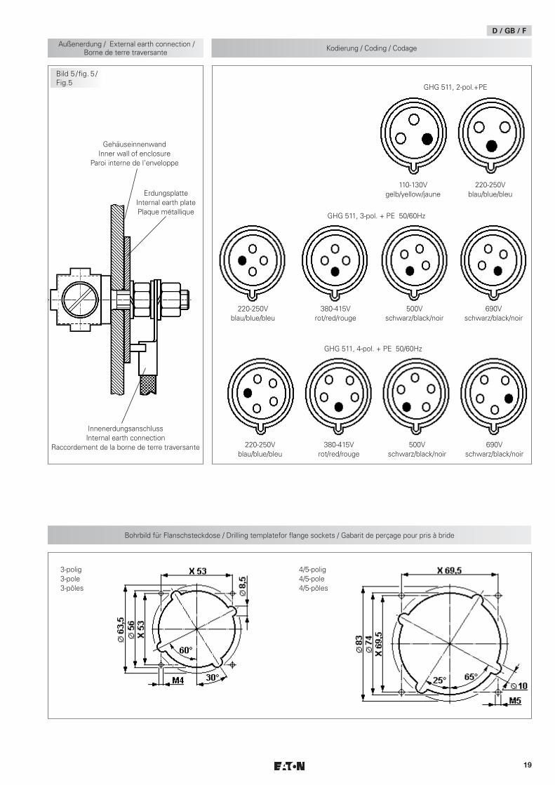
Ist eine separate „Außenerdung” am Kunststoffgehäuse angebracht, darf dieser Anschluss mit einer Leitung von max. 25 mm² angeschlossen werden.
Dieser Außenerdungsanschluss ist innen im Gehäuse für einen Kabelschu-hanschluss mit einem Loch für M6 ausgelegt (siehe auch Seite 19, Bild 5).
Achtung: Metallplatten und Metallverschraubungen müssen in den Potentialausgleich miteinbezogen werden.
6.4 Schließen des Gerätes
Zur Sicherstellung der erforderlichen Mindestschutzart sind die Deckel-schrauben, die Schrauben der Stecker und der Kupplung fest anzuziehen.
Alle Fremdkörper sind aus dem Gerät zu entfernen.
Bei übermäßigem Anziehen kann die Schutzart beeinträchtigt werden.
6.5 Inbetriebnahme
Vor Inbetriebnahme des Betriebsmittels sind die in den einzelnen nationalen Bestimmungen genannten Prüfungen durchzuführen. Außerdem ist vor der Inbetriebnahme die korrekte Funktion und Installation des Betriebsmittels in Übereinstimmung mit dieser Betriebsanleitung und anderen anwendbaren Bestimmungen zu überprüfen.
Vor jedem Stecken des Steckers in die Steckdose ist dieser auf Beschädigungen zu überprüfen.
Der Betreiber muss dafür sorgen, dass beim Betrieb der Steckvorrichtung überall ein gleiches Erdpotential anliegt.
Unsachgemäße Installation und Betrieb der Steckvorrichtungen kann zum Verlust der Garantie führen.
DExplosionsgeschützte Steckvorrichtungen 16 A, 3-polig, 4-polig, 5-polig, GHG 511
7 Instandhaltung/WartungDie für die Wartung/Instandhaltung von elektrischen Betriebsmitteln in explosions gefährdeten Bereichen geltenden natio nalen Bestim-mungen (z.B. EN/IEC 60079-17) sind einzuhalten.
Vor Öffnen des Gehäuses Spannungsfreiheit sicherstellen oder geeignete Schutzmaß nahmen ergreifen.
Die erforderlichen Wartungsintervalle sind anwendungsspezifisch und daher in Abhängigkeit von den Einsatzbedingungen vom Betreiber festzulegen.
Im Rahmen der Wartung sind vor allem die Teile, von denen die Zünd-schutzart abhängt, zu prüfen (z.B. Unversehrtheit der druckfesten Kompo-nenten, des Gehäuses, der Dichtungen und der Kabel- und Leitungseinfüh-rung).
Sollte bei einer Wartung festgestellt werden, dass Instandsetzungsarbeiten erforderlich sind, ist Abschnitt 8 dieser Betriebsanleitung zu beachten.
7.1 Wandsteckdose und Kupplung
Die 4 Bestigungsschrauben des Flansches sind in die Wartungsintervalle mit einzubeziehen. Hierbei ist das Prüfdrehmoment (sieh Technische Daten) der 4 Befestigungsschrauben zu überprüfen.
8 Reparatur/Instandsetzung/ÄnderungenInstandsetzungsarbeiten/Reparaturen dürfen nur mit Cooper Crouse-Hinds Original ersatzteilen vorgenommen werden.
Bei Schäden an der druckfesten Kapselung ist das betroffene Betriebsmittel an Cooper Crouse-Hinds zur Reparatur zurückzugeben.
Reparaturen, die den Explosionsschutz betreffen, dürfen nur von Cooper Crouse-Hinds oder einer qualifizierten Elektro fachkraft in Übereinstimmung mit national geltenden Regeln durchgeführt werden (EN/IEC 60079-19).
Umbauten oder Änderungen am Betriebs- mittel sind nicht gestattet.
9 Entsorgung / Wiederverwertung
Bei der Entsorgung des Betriebsmittels sind die jeweils geltenden nationalen Abfallbeseitigungsvorschriften zu beachten.
Zusätzliche Informationen zur Entsorgung des Produktes können Sie bei Ihrer zuständigen Cooper Crouse-Hinds Niederlassung erfragen.
Zur Erleichterung der Wiederverwertbarkeit von Einzelteilen sind Kunststoffteile mit dem Kennzeichen des verwendeten Kunststoffes versehen.
Programmänderungen und -ergänzungen sind vorbehalten.

88
Explosion protected plug and socket system 16 A, 3-pole, 4-pole, 5-pole, GHG 511
1 Technical data
ATEX type examination certificate / IECEx Certificate of Conformity:Wall socket GHG 511 4. BVS 17 ATEX E 053 X IECEx BVS 17.0045 XPlug GHG 511 7. BVS 17 ATEX E 053 X IECEx BVS 17.0045 XCoupler GHG 511 3. BVS 17 ATEX E 053 X IECEx BVS 17.0045 XFlange socket GHG 511 8. BVS 15 ATEX E 101 U IECEx BVS 15.0088 UPlug GHG 543 2. PTB 99 ATEX 1039 IECEx BVS 04.0002Plug GHG 531 7. PTB 99 ATEX 1039 IECEx BVS 04.0002Marking acc. to 2014/34/EU and the series of standards EN 60079:
D II 2 G Ex db eb [ia] IIC / IIB / IIB+H2 T6 / T5 GbD II 2 D Ex tb IIIC T80 °C Db
Flange socket GHG 511 8 D II 2 G Ex db eb IIC / IIB / IIB+H2 Gb D II 2 D Ex tb IIIC / IIIB Db
Category of application and the series of standards IEC 60079:Ex db eb [ia] IIC / IIB / IIB+H2 T6 / T5 GbEx tb IIIC T80 °C Db
Rated voltage:GHG 511 - 3-pole up to 415 V, 50/60 Hz; max 400 HzGHG 511 - 4-pole up to 690 V, 50/60 Hz; max 400 HzGHG 511 - 5-pole up to 690 V, 50/60 Hz; max 400 HzPlug GHG 543 2. up to 250 V, 50/60 HzPlug GHG 531 7. up to 690 V, 50/60 Hz(Special voltages and various contact-marking are possible on request.)
Gasgroupe Perm. ambient temperature:IIB IIB+H2 IIC
XATEX - IEC Install protected against
higher mechanical risk. Max 4JType maximum rated current
Wall socket GHG 51.4...R.... / Flange socket GHG 51.8...R.... / 3p (default temperature range).. 16 A - - -45 °C ... +55 °C
- 16 A - -30 °C ... +55 °C- - 16 A -20 °C ... +55 °C
Wall socket GHG 51.4...R.1.. / Flange socket GHG 51.8...R.1.. / 3/4/5p (Extendet temperature range)16 A 16 A - -55 °C ... +45 °C10 A 10 A - -55 °C ... +55 °C- - 16 A -20 °C ... +45 °C- - 10 A -20 °C ... +55 °C
Wall socket GHG 51.4...R.... / Flange socket GHG 51.8...R.... / 4/5p (default temperature range)16 A 16 A - -55 °C ... +55 °C- - 16 A -20 °C ... +55 °C
Coupler GHG 51.3...R.... 16 A 16 A 16 A -20 °C ... +55 °C
Plug GHG 51.7...R.... ( min. 2.5 mm²)16 A 16 A 16 A -40 °C ... +45 °C -55 °C ... +45 °C
Plug GHG 51.7...R.... ( min. 4.0 mm²)16 A 16 A 16 A -40 °C ... +55 °C -55 °C ... +55 °C
Plug GHG 51.7...R.... ( min. 2.5 mm²)10 A 10 A 10 A -40 °C ... +55 °C -55 °C ... +55 °C
Stecker GHG 51.7...R.... ( 1,5 - 2,5 mm²) ( 4,0 mm²)16 A 16 A 16 A -20 °C ... +40 °C -55 °C ... +40 °C
Plug GHG 543 2. / GHG 531 7.16 A 16 A 16 A -20 °C ... +40 °C
(Special versions permit deviating temperatures)
Back-up fuse: GHG 511 GHG 543/531without thermal protection 20 A 16 Awith thermal protection 35 A gG 32 A gGSwitching capacity AC 3 3-pole: 250 V/16 ASwitching capacity AC 3 4-pole: 400 V/16 ASwitching capacity AC 3 5-pole: 500 V/16 A
Protection category acc. to EN/IEC 60529 IP 66 (catalogue version)(1)
(1) with closed and secured hinged cover as well as combinations properly plugged together. Attention! When the Plugs GHG 543/531 is insert with sockets of the series GHG 511, the "IP" protection category of the combination is reduced to the minimum protection category "IP 54".
Insulation class acc. to IEC/EN 61140: I – with metal flange or metal cable entries II - is complied with by devices
GB

99
Cable entry: (catalogue version)Wall socket 2 x M25 1 x M25 + 1 x screwed blanking plugSuitable cables and test torques of the pressure screw (Ømm/Nm) (Default plastic KLE GHG960)
M20 M25 M32
Seal 1+2+3 1 2 3 min. max. (2)
5.5/1.5 7.0/1.0
8.0/1.5 10.0/2.0
Seal 1+2 1 2 3 min. max. (2)
7.0/1.5 9.0/1.4
10.0/2.3 13.0/2.6
14.0/3.0 17.0/4.0
Seal 1 1 2 3 min. max. (2)
9.5/1.0 13.0/1.7
13.5/1.3 17.5/2.3
17.5/1.5 21.0/1.3
Test torque for screw in thread cable entry (Nm) 2.7 3.0 5.0(2) The tests of clamping ranges and torque values were performed with metal mandrel. The clamping range can vary by using cables with different manufacturing tolerances
and material properties. Please use a suitable combination of seals in the intermediate area, so that the cap nut can be tightened in future maintenance work on the cable entry.
Suitable cablesSupply terminals / Clamping range:
Stripped wire length
Wall socket / Flange socket 2 x 1.5 - 4.0 mm2 10 mmPlug 3-pole Ø 8 - 18 mm 1 x 1.5 - 4.0 mm² (3) (4) 9 mmCoupler 3-pole Ø 8 - 19 mm 1 x 1.5 - 4.0 mm² (3) 10 mmPlug / Coupler 4-pole Ø 8 - 21 mm 1 x 1.5 - 4.0 mm² (3) (4) 9 mm / 10 mmPlug / Coupler 5-pole Ø 12 - 21 mm 1 x 1.5 - 4.0 mm² (3) (4) 9 mm / 10 mmPlug GHG 543/531 Ø 9 - 17 mm 1 x 1.0 - 4.0 mm2 8 mm(3) only with pin cable lugs (4) observe Perm. ambient temperature!Test torques:Supply terminals Wall socket / Flange socket 2,5 Nm
Coupler 2,5 NmPlug 1,5 Nm
Cover screws 2.5 NmTerminals 2.5 NmMounting screws flange socket 1.6 NmSelf-cutting screws size 4 1.6 Nm (Page 15: Fig. 3; Pos. 3)Locking screw for pressure piece GHG 54 1.6 Nm
Weight: (catalogue version)Wall socket 3-pole GHG 511 43 approx. 1.10 kgPlug 3-pole GHG 511 73 approx. 0.27 kg / GHG 543 - approx. 0.23 kgCoupler 3-pole GHG 511 33 approx. 0.61 kgFlange socket 3-pole GHG 511 83 approx. 0.38 kgWall socket 4-pole GHG 511 44 approx. 1.50 kgPlug 4-pole GHG 511 74 approx. 0.34 kg / GHG 531 - approx. 0.40 kgCoupler 4-pole GHG 511 34 approx. 0.89 kgFlange socket 4-pole GHG 511 84 approx. 0.53 kgWall socket 5-pole GHG 511 45 approx. 1.55 kgPlug 5-pole GHG 511 75 approx. 0.38 kg / GHG 531 - approx. 0.41 kgCoupler 5-pole GHG 511 35 approx. 0.89 kgFlange socket 5-pole GHG 511 85 approx. 0.58 kg
1.1 Auxiliary contact
1 Technical data
Auxiliary contact, rated voltage: 250 VACAuxiliary contact, rated current: AC / 5 A DC / 0.03 A
Explosion protected plug and socket system 16 A, 3-pole, 4-pole, 5-pole, GHG 511
GB

10
2 Principles Caution This symbol warns of a possible failure. Failure to observe this caution may result in the total failure of the device or the system or plant to which it is connected.
XATEX - IEC Special conditions
This symbol shows Highlights for safe use in accordance to EU-Type-Ex-amination Certificate/ IEC Ex-Certificate of Conformity.
2.1 Safety instructionsTarget group: For skilled electricians and suitable qualified, instructed personnel in accordance with national legislation, including
the relevant standards and, where applicable, in acc. with IEC/EN 60079-14 on electrical apparatus for explosive atmospheres.
They are not suitable for Zone 0 and Zone 20 hazardous areas. The temperature class and explosion group marked on the apparatus shall be observed.
Modifications to the plugs and sockets or changes of their design are not permitted. They shall be used for their intended purpose and in perfect and clean condition.
The requirements of the IEC/EN 60079-31 regarding excessive dust deposits and temperature to be considered from the user.
To ensure adherence to the temperature class stated on the type label of the apparatus, the permissible ambient temperature, the rated terminal cross section and the self heating of the apparatus that is mainly due to the power dissipation shall be taken into account (test criterion for the self heating is an overload of 10%).
Prior to taking the plugs and sockets into operation, they will have to be checked in accordance with the instruction as per section 6. The sockets may only be used with the associated Cooper Crouse-Hinds plugs in undamaged condition.
The interlocking switch of the socket is mechanically secured and cannot be connected without plug.
The plugs GHG 543/531 can further on be inserted with the sockets of the series GHG 543/GHG531.
Flange sockets may only be used in protective enclosure or apparatus that have been certified for the respective application.
Observe the national safety rules and regulations for prevention of accidents as well as the safety instructions included in these operating instruc-tions and set in italics the same as this text!
3 Conformity with standardsThe apparatus is conform to the standards specified in the EU-Declaration of conformity, enclosed separately.
References to standards and directives in these operating instructions always relate to the latest version. Other additions (e.g. details relating to the year) shall be observed.
4 Field of applicationThe plugs and sockets GHG 511 are suitable for use in Zones 1 and 2 as well as in Zones 21 and 22 in accordance with IEC/EN 60079-10-1 and IEC/EN 60079-10-2.
The enclosure materials employed, including the exterior metal parts, are made of high- quality materials which ensure a corrosion protection and resistance to chemical substances corresponding to the requirements in a “normal industrial atmosphere”:
- impact resistant polyamide - glass-fibre reinforced polyester - special steel AISI 316 L
When used in extremely aggressive atmosphere, you can request additional information on the chemical resistance of plastics used in your responsible Cooper Crouse-Hinds branch.
5 Use/PropertiesThe GHG 511 plugs and sockets are used for the power supply of local controls with varying locations, as well as of electrical installations, mobile machinery and driving gear in hazardous areas.
The low-voltage plugs and sockets GHG 511 are fitted with a load switch and can be used up to max. 16 A (see technical data). The plugs and sockets can generally be used for the voltage range laid down in IEC/EN 60309 (e.g. UN 400V that corresponds to the voltage range 380-415V).
The apparatus connected to the plug shall be suitable for the applied mains voltage.
In order to switch on the socket, the plug is inserted, pushed fully home and then turned through approx. 45° to the right. Thereby the plug is locked in the socket (see page 18, fig. 1).
For switching off and pulling the plug, proceed in inverse order.
After separating the plug from the socket, the latter shall be closed with the hinged cover and secured with the bayonet ring. The plug can be pushed into the socket and pulled out of it only whilst the socket is switched off.
In order to ensure the socket’s type of protection acc. to the type label also with the plug being inserted, the bayonet ring of the plug (see page 18, fig. 2, item 2) is turned to its stop onto the socket.
The data as per point 3 and 4 will have to be taken into account with the use. Applications other than described are not permitted without Cooper Crouse-Hinds’s prior written consent.
For the operation, the instructions stated in section 7 of the operat-ing instructions will have to be observed.
From time to time, the locking function protecting against inappro-priate use e. g. of industrial plugs in zone 1 has to be checked.
In the open air, the plugs must be kept with the plug opening (pin side) pointing downwards or be closed with protective plug caps available as an optional extra (see general catalogue).
Explosion protected plug and socket system 16 A, 3-pole, 4-pole, 5-pole, GHG 511
GB

11
The user alone is responsible for the appropriate use of this plug and socket system in consideration of the basic conditions existing at the plant (see technical data).
After a short in the circuit, the functioning of the plug and socket system and of the plugs has to be checked.
Since the switch contacts can no more be checked because of the flameproof enclosure, the complete switch insert (flange socket) will have to be replaced after repeated short circuits.
6 InstallationFor the mounting and operation, the respective national regulations as well as the general rules of engineering will have to be observed (IEC/EN 60079-14).
The improper installation and operation of plugs and sockets may result in the invalidation of the guarantee.
6.1 Mounting
The wall sockets can be mounted without opening their enclosure.
XATEX - IEC If an ambient temperature between -40 °C and -55 °C is to be expected
when used as intended, the wall sockets may only be installed in a protected location. The impact energy shall not exceed 4 joules.
In case the wall sockets are mounted directly onto the wall, they may rest evenly only at the respective fastening points. The chosen screw shall match the fastening hole (see dimensional drawing) and it must not damage the hole (e. g. use of a washer).
The device shall be fastened diagonally with at least 2 screws.
The wall sockets, flange sockets and couplers shall be mounted so that the plug hole points downwards (see page 18, fig. 2).
The wall sockets can be clipped onto the Cooper Crouse-Hinds mounting plate size 4. They are laterally pushed into the guiding groove on the left-hand side of the mounting plate.
The respective mounting instructions will have to be observed.
B
B
B
B
A A
AA
Fastening point A Fastening point B 16 A socket 3-pol. 16 A socket 4,5-pol.
6.2 Opening the device/ Electrical connection
Before opening the apparatus, ensure that it has been isolated from the voltage supply, or take appropriate protective measures.
The electrical connection of the device may only be carried out by skilled staff (IEC/EN 60079-14).
The conductors shall be connected with special care in order to maintain the explosion category.
The insulation of the conductors shall reach up to the terminal. The conductor itself shall not be damaged.
The connectible min. and max. conductor cross-sections shall be observed (see technical data).
Taking into account the respective regulations, the properly bared conductors of the cables shall be connected.
The plug insert (page 18, item 2, fig. 4) is removed from the pin bushing (page 18, item 1, fig. 4), after the fastening screws (item 3, fig. 3) have been unscrewed. Thereafter, the plug insert can be connected to the connections of the plug pins (see page 18, view 1, fig. 4).
Attention: When the fastening screws (page 18, item 3, fig. 3) get lost, they will have to be replaced by similar screws or to be ordered directly from the manufacturer.
Assembly is made in inverse order, after the cable has been connected.
To connect the coupler, unscrew and remove the 4 fixing screws of the flange from the body sleeve. The coupler insert can then be connected to the respective contacts. When reassembling, the flange screws shall be screwed into the body sleeve with a maximum test torque of 1 Nm.
All screws and / or nuts of the supply terminals, also of those remaining vacant, shall be tightened down.
Excessive tightening may affect or damage the connection.
The supply terminals are designed for the connection of copper conduc-tors.
If multi- or fine-wire connecting cables are used, the wire ends will have to be handled in acc. with the applicable national and international rules (e.g. use of sleeves for strands).
6.3 Cable entries (KLE); blanking plugs
6.3.1 Socket
Generally, only certified cable entries and blanking plugs are permitted for use. Flexible cables shall be used with trumpet-shaped cable glands or other suitable entries with additional pull-relief.
When using cable entries with a lower IP protection than that which applies to the device (see technical data), the IP protection of the whole device will be reduced. The mounting directives applicable to the cable entries used shall be observed.
Unused holes shall be closed with a certified blanking plug in order to establish the minimum protection category. Care has to be taken that when fitting the cable entries, sealing inserts appropriate to the cable diameter are used. In case of sealing inserts that are cut out, it shall be ensured that the insert is properly adapted to the cable diameter.
In order to ensure the required minimum protection category, the cable glands are to be tightened down.
Explosion protected plug and socket system 16 A, 3-pole, 4-pole, 5-pole, GHG 511

12
Explosion protected plug and socket system 16 A, 3-pole, 4-pole, 5-pole, GHG 511
GB
Overtightening might impair the protection category.
All vacant metric Cooper Crouse-Hinds cable entries shall be closed with the certified blanking plug for metric cable entries.
Warning: Metal plates and metal glands shall be incorporated in the potential equalization.
6.3.2 Plug/coupler
In general, only the sealing inserts fitted in the plug or in the coupler may be used. When mounting the cable, attention has to be paid that sealing inserts matching the cable diameter be used. After having connected the cable, the coupling ring (page 18, fig. 2, item 4) is to be screwed fingertight until the sealing effect is obtained. Then the screws item 5, of the pull-relief item 6, are to be tightened down.
Mind! Overtightening might impair the pull- relief effect!
In case an ”external earth connection“ is mounted on the plastic enclosure, it should be connected with a max. 25 mm² wire.
This earth connection is inserted through a M6 drill in the inner wall of the enclosure(see page 19, fig. 5).
Warning: Metal plates and metal glands shall be incorporated in the potential equalization.
6.4 Closing the device
In order to ensure the required minimum protection category, the cover screws, the screws of the plug and of the coupler shall be tightened down. The screws of the plug and the coupler shall be tightened down.
Overtightening might impair the protection category.
Any foreign matter shall be removed from the device.
6.5 Taking into operation
Prior to taking the apparatus into operation, the tests specified in the relevant national regulations shall be carried out. Apart from that, the correct functioning and installation of the apparatus in accordance with these operating instructions and other applicable regulations will have to be checked.
Check the plug for any damages before putting it in the socket.
The user must ensure that a uniform equipotential earth applies through-out when the plug and socket system is operated.
The inappropriate installation and operation of the plugs and sockets can entail the loss of warranty.
7 Maintenance/ServicingThe relevant national regulations which apply to the maintenance/servicing of electrical apparatus in explosive atmospheres, shall be observed (IEC/EN 60079-17).
Before opening the enclosure, make sure that the device is discon-nected from the voltage, or take appropriate protective measures.
The required maintenance intervals depend on the specific application and will therefore have to be determined by the user dependent on the conditions of use.
When servicing the plugs and sockets, parti cularly those parts that are decisive for their type of protection against explosion will have to be checked (e. g. intactness of flameproof enclosed components, of the housing, firm fit of the cable entries and efficacy of gaskets).
If during servicing, repairs prove to be necessary, section 8 of these operating instructions will have to be observed.
7.1 Wallsocket and coupler
The 4 fixing screws of the flange socket have to be considered in the maintenance intervals too. The test torque have to be checked (see Technical data).
8 Repair/Overhaul/ ModificationsRepairs and overhaul may only be carried out with genuine Cooper Crouse-Hinds spare parts.
Should the flameproof enclosure be damaged, only a replacement will be permitted. In case of doubt, the respective apparatus will have to be returned to Cooper Crouse-Hinds for repair.
Repairs that affect the explosion protection, may only be carried out by Cooper Crouse-Hinds or a qualified electrician in compliance with the applicable national rules (IEC/EN 60079-19).
Modifications to the device or changes of its design are not permitted.
9 Disposal/Recycling
When the apparatus is disposed of, the respective national regulations on waste disposal will have to be observed.
In case of disposal you can obtain additional information from your Cooper Crouse-Hinds branch.
In order to facilitate the recycling of individual components, plastic parts are provided with the identification mark of the plastic material used.
Subject to modifications or supplement of the product range.

13
FFiches et prises de 16 A, à 3 pôles, 4 pôles, 5 pôles, pour atmosphères explosives, GHG 511
1 Caractéristiques techniques
UE-Certificat de Conformité / IECEx Certificat de Conformité:Prise murale GHG 511 4. BVS 17 ATEX E 053 X IECEx BVS 17.0045 XFiche GHG 511 7. BVS 17 ATEX E 053 X IECEx BVS 17.0045 XProlongateur GHG 511 3. BVS 17 ATEX E 053 X IECEx BVS 17.0045 XPrise à bride GHG 511 8. BVS 15 ATEX E 101 U IECEx BVS 15.0088 UFiche GHG 543 2. PTB 99 ATEX 1039 IECEx BVS 04.0002Fiche GHG 531 7. PTB 99 ATEX 1039 IECEx BVS 04.0002Marquage selon 2014/34/UE et directive la série standard EN 60079:
D II 2 G Ex db eb [ia] IIC / IIB / IIB+H2 T6 / T5 GbD II 2 D Ex tb IIIC T80 °C Db
Prise à bride GHG 511 8 D II 2 G Ex db eb IIC / IIB / IIB+H2 Gb D II 2 D Ex tb IIIC / IIIB Db
Marquage selon et directive la série standard IEC 60079:Ex db eb [ia] IIC / IIB / IIB+H2 T6 / T5 GbEx tb IIIC T80 °C Db
Tension nominale:GHG 511 - 3-pôles jusqu’à 415 V, 50/60 Hz; max 400 HzGHG 511 - 4-pôles jusqu’à 690 V, 50/60 Hz; max 400 HzGHG 511 - 5-pôles jusqu’à 500 V, 50/60 Hz; max 400 HzFiche GHG 543 2. jusqu’à 250 V, 50/60 HzFiche GHG 531 7. jusqu’à 690 V, 50/60 Hz(Des tensions spéciales sont possibles sur demande)
Groupe de gaz Température ambiante admissible:IIB IIB+H2 IIC X
ATEX - IEC Installateur protégé contre les risques mécaniques plus élevés. Maxi 4J
Type: Courant nominal maximal:
Prise murale GHG 51.4...R.... / Prise à bride GHG 51.8...R.... / 3p (plage de température standard)16 A - - -45 °C ... +55 °C- 16 A - -30 °C ... +55 °C- - 16 A -20 °C ... +55 °C
Prise murale GHG 51.4...R.1.. / Prise à bride GHG 51.8...R.1.. / 3/4/5p (plage de température étendue)16 A 16 A - -55 °C ... +45 °C10 A 10 A - -55 °C ... +55 °C- - 16 A -20 °C ... +45 °C- - 10 A -20 °C ... +55 °C
Prise murale GHG 51.4...R.... / Prise à bride GHG 51.8...R.... / 4/5p (plage de température standard)16 A 16 A - -55 °C ... +55 °C- - 16 A -20 °C ... +55 °C
Prolongateur GHG 51.3...R.... 10 A 10 A 10 A -20 °C ... +55 °C
Fiche GHG 51.7...R.... ( min. 2,5 mm²)
16 A 16 A 16 A -40 °C ... +45 °C -55 °C ... +45 °CFiche GHG 51.7...R.... ( min. 4,0 mm²)
16 A 16 A 16 A -40 °C ... +55 °C -55 °C ... +55 °C
Fiche GHG 51.7...R.... ( min. 2,5 mm²)10 A 10 A 10 A -40 °C ... +55 °C -55 °C ... +55 °C
Stecker GHG 51.7...R.... ( 1,5 - 2,5 mm²) ( 4,0 mm²)16 A 16 A 16 A -20 °C ... +40 °C -55 °C ... +40 °C
Fiche GHG 543 2. / GHG 531 7.16 A 16 A 16 A -20 °C ... +40 °C
(En cas de modèles spéciaux d’autres températures possibles.)Fusible maximal placé en amont au maxi.: GHG 511 GHG 543/531sans protection thermique 20 A 16 Aavec protection thermique 35 A gG 32 A gGPuissance de coupure AC 3, 3-pôles: 250 V/16 APuissance de coupure AC 3, 4-pôles: 400 V/16 APuissance de coupure AC 3, 5-pôles: 500 V/16 AIndice de protection selon CEI/EN 60529 IP 66 (modèle de liste)(1)
(1) avec le couvercle rabattant fermé et arrêté et les dispositifs dûment enfichés. Attention! Le fait de combinier de fiches, GHG 543/531 avec les prises et les prolongateurs de série GHG511entraîne une réduction du degré de protection à son minimum:. IP54.
Classe d’isolation selon CEI/EN 61140: I – version avec plaque laiton pour câbles armés ou Entrées de câble de metal II - est remplie par les dispositifs

14
FFiches et prises de 16 A, à 3 pôles, 4 pôles, 5 pôles, pour atmosphères explosives, GHG 511
Entrée de câble: (modèle de liste)Prise murale 2 x M25 1 x M25 + 1 x bouchon de fermetureDimensions des câbles et couples de serrage / Entrées de câble (Ømm/Nm)
M20 M25 M32
Garniture 1+2+3 1 2 3 min. max. (2)
5,5/1,5 7,0/1,0
8,0/1,5 10,0/2,0
Garniture 1+2 1 2 3 min. max. (2)
7,0/1,5 9,0/1,4
10,0/2,3 13,0/2,6
14,0/3,0 17,0/4,0
Garniture 1 1 2 3 min. max. (2)
9,5/1,0 13,0/1,7
13,5/1,3 17,5/2,3
17,5/1,5 21,0/1,3
Couple d' essai pour l’entrée de câble (Nm) 2,7 3,0 5,0(2) Les tests des plages de serrage et les valeurs de couple de serrage ont été réalisés avec un mandrin métallique. La plage de serrage peut varier légèrement selon le type
de câble et les propriétés des matériaux utilisés. Pour les plages de serrage intermédiaires, veuillez utiliser des garnitures d’étanchéité qui laisseront la possibilité de resserrer le chapeau du presse étoupe lors de futures opérations de maintenance.
Dimensions des câbles Section transv. / Plage de serrage: Longueur dénudée des fils
Prise murale / Prise à bride 2 x 1,5 - 4,0 mm2 10 mmFiche 3-pôles Ø 8 - 18 mm 1 x 1,5 - 4,0 mm² (3) (4) 9 mmProlongateur 3-pôles Ø 8 - 19 mm 1 x 1,5 - 4,0 mm² (3) 10 mmFiche / Prolongateur 4-pôles Ø 8 - 21 mm 1 x 1,5 - 4,0 mm² (3) (4) 9 mm / 10 mmFiche / Prolongateur 5-pôles Ø 12 - 21 mm 1 x 1,5 - 4,0 mm² (3) (4) 9 mm / 10 mmFiche GHG 543/531 Ø 9 - 17 mm 1 x 1,0 - 4,0 mm2 8 mm(3) fil souple avec cosse 4,0 mm² (4) Respecter Température ambiante admissible!Torques d’essai:
Prise murale / Prise à bride 2,5 NmProlongateur 2,5 NmFiche 1,5 Nm
Vis de couvercle 2,5 NmBride de la vis de fixation 1,6 NmVis auto-taraudeuse taille 4 1,6 Nm (Page 15: Fig. 3; Pos. 3)Vis d´arrêt á piece de pression GHG 54 1,6 Nm
Poids: (modèle de liste)Prise murale 3-pôles GHG 511 43 env. 1,10 kgFiche 3-pôles GHG 511 73 env. 0,27 kg / GHG 543 - env. 0,23 kgCoupler 3-pôles GHG 511 33 env. 0,61 kgPrise à bride 3-pôles GHG 511 83 env. 0,38 kgPrise murale 4-pôles GHG 511 44 env. 1,50 kgFiche 4-pôles GHG 511 74 env. 0,34 kg / GHG 531 - env. 0,40 kgCoupler 4-pôles GHG 511 34 env. 0,89 kgPrise à bride 4-pôles GHG 511 84 env. 0,53 kgPrise murale 5-pôles GHG 511 45 env. 1,55 kgFiche 5-pôles GHG 511 75 env. 0,38 kg / GHG 531 - env. 0,41 kgCoupler 5-pôles GHG 511 35 env. 0,89 kgPrise à bride 5-pôles GHG 511 85 env. 0,58 kg
1 Caractéristiques techniques
Contact auxiliaire, tension nominale: 250 VACContact auxiliaire, courant nominal: AC / 5 A DC / 0,03 A
1.1 Contact auxiliaire

15
2 LégendeAttention
Ce symbole met en garde contre un éventuel défaut. Le non-respect de cette consigne peut entrainer une panne totale de l’appareil ou du système ou de l’installation à laquelle il est connecté.
XATEX - IEC Conditions particulières:
Ce symbole indique la présence de conditions particulières d’utilisation à respecter, en lien avec l’attestation d’examen UE de type et le certificat IEC Ex.
2.1 Consignes de sécuritéGroupe cible: Pour les électriciens qualifiés et les personnels ayant reçu les formations adéquates, conformément à la législation
nationale en vigueur et, si applicable, à la norme CEI/EN 60079-14 sur les installations électriques pour les atmosphères explosives.
Les fiches et prises du type GHG 511, pour atmosphère explosive ne sont pas appropriées à la zone 0 et zone 20. Respecter la classe de températures et le type de protection contre l'inflammation indiqués sur les appareils.
Il n’est pas admis de transformer ou de modifier les fiches et prises. Elles ne doivent être employées que pour la fonction qui leur est dévolue et qu’en parfait état de propreté et de fonctionnement.
Les exigences des CEI/EN 60079-31 en ce qui concerne des dépôts de poussière démesurés et une température doivent être considérées par I’utilisateur.
Afin de respecter la classe de température indiquée sur l’étiquette du type de l’appareil, on prendra en compte la température ambiante, le diamètre de connexion ainsi que les pertes d’énergie occasionnées par l’échauffement propre de l’appareil (le critère de contrôle limite pour l’échauffement est une surcharge de 10%).
Avant leur mise en service, les fiches et prises doivent être vérifiées selon l’instruction donnée dans la section 6. Ce coffret prises doit être utilisé uniquement en association avec des fiches de marque Cooper Crouse-Hinds en bon état.
L’insert de la prise est protégé mécanique- ment et ne peut donc pas être mis en circuit sans fiche.
Les fiches GHG 543/GHG 531 on à utilesér future avec les prises GHG 543 / GHG 531.
Les prises à bride doivent être installés exclusivement dans les boîters de protection ou sur les appareils dûment prévus pour le champ d’application correspondant.
Respectez les prescriptions nationales de sécurité et de prévoyance contre les accidents ainsi que les consignes de sécurité qui suivent dans ce mode d’emploi et qui sont mises en italique comme ce texte!
3 Conformité avec les normesLes Appareils sont conformes aux normes reprises dans la déclaration de conformité, jointe séparément.
Les références aux normes et directives dans cette notice se réfèrent toujours à la dernière version. Les suppléments éventuels doivent également être respectés.
4 Domaine d’utilisationLes fiches et prises du type GHG 511 conviennent à l’emploi en les zones 1 et zones 2 ainsi que l’emploi en zones 21 et zones 22 d’une atmosphère explosive selon CEI/EN 60079-10-1 et CEI/EN 60079-10-2!
Pour l’enveloppe, y compris les pièces métalliques extérieures, des matières de qualité supérieure ont été employées qui assurent une protection appropriée contre la corrosion et une résistance contre des agents chimiques en “atmosphère industrielle normale”: - polyamide résistant au choc - polyester renforcé par fibre de verre - acier spécial AISI 316
En cas d‘utilisation en atmosphère extrèmement corrosive, vous pouvez obtenir des informations complémentaires sur la résistance chimique des plastiques utilisés chez la succursale Cooper Crouse-Hinds de votre région.
5 Utilisation/PropriétésLes fiches et prises GHG 511 servent à l’alimentation en courant de réglages auto matiques en place à emplacement variable et d’installations électriques ainsi que de machines et de mécanismes de commande mobiles en atmosphère explosive.
Les fiches et prises GHG 511 pour basses tensions sont dotées d’un sectionneur à coupure en charge et peuvent être exploitées jusqu’à 16 A au maxi (voir Caractéristiques techniques). Les prises et fiches sont utilisables dans les fourchettes de tension comprises dans la norme CEI/EN 60309 (par exemple, UN 400V appartient à la fourchette 380 - 415V).
L’appareil connecté à la fiche doit être adapté à la tension du réseau correspondant.
Pour la mise en circuit de la prise, la fiche doit être enfichée jusqu’à sa butée dans celle-ci et ensuite être tournée de 45° à droite. De cette manière, la fiche est bloquée dans la prise (voir page 18, fig. 1).
Pour la mise hors circuit de la prise et pour retirer la fiche, procédez dans l’ordre inverse.
Après avoir séparé la fiche de la prise, celle-ci est fermée avec le couvercle à charnière et bloquée avec l’anneau à baïonnette. La fiche ne peut être enfichée dans la prise ou retirée de celle-ci que lorsque la prise est mise hors circuit.
Afin d’assurer le mode de protection selon la plaque signalétique après la mise en circuit de la prise avec la fiche mise en place, l’anneau à baïonnette de la fiche (page 18, fig. 2, pos. 2) est tourné jusqu’à sa butée sur la prise.
Pour l’emploi, les consignes des sections 3 et 4 devront être respectées. Des emplois autres que ceux décrits ne sont admis qu’avec le consentement par écrit de la part de Cooper Crouse-Hinds.
Lors de l’exploitation, les instructions selon point 7 de ce mode d’em-ploi doivent être respectées.
De temps en temps, la fonction de bloquage par ex. des fiches industrielles qui sert de protection contre l’emploi non convenable en zone 1, doit être vérifiée.
En plein air, les fiches doivent être gardées avec leur ouverture (côté des broches) vers le bas. A l’option, elles peuvent être fermées avec les capuchons protecteurs pour la fiche qui sont disponibles sur demande (voir catalogue général).
FFiches et prises de 16 A, à 3 pôles, 4 pôles, 5 pôles, pour atmosphères explosives, GHG 511

16
Seul l’utilisateur est responsable de l’emploi comme prévu de cette fiche et prise, en tenant compte des conditions générales existant dans l’établissement (voir caractéristiques techniques).
Après un court-circuit dans le circuit, le fonctionnement de la prise et de la fiche doit être vérifié.
Etant donné que les contacts de commutation ne peuvent plus être vérifiés en raison de l’enveloppe antidéflagrante, l’insert de commutation complet (prise à bride) devra être remplacé après des courts-circuits répétés.
6 InstallationPour l’installation et l’exploitation d’appareils électriques pour atmosphère explosive, la règlementation nationale en vigueur ainsi que les règles de la technique généralement reconnues devront être respectées (CEI/EN 60079-14).
L’installation inadéquates des fiches et prises peuvent entraîner la perte de la garantie.
6.1 Montage
Le montage des prises murales peut se faire sans ouvrir l’enveloppe.
XATEX - IEC Si une température ambiante comprise entre -40 °C et -55 °C est à
prévoir lors de l'utilisation conforme, les prises murales ne doivent être installées que dans un endroit protégé. L'énergie d'impact ne doit pas dépasser 4 joules.
En cas de montage directement au mur, les prises murales ne doivent reposer au niveau du mur qu’en les points de fixation prévus. La vis choisie doit correspondre au trou de fixation (voir plan coté) et elle ne doit pas avarier l’ouverture (par ex. emploi d’une rondelle).
Le dispositif doit être fixé en diagonale avec au moins deux vis.
Le montage de la prise murale, de la prise à bride et du prolongateur doit se faire de sorte que l’ouverture d’enfichage soit dirigée vers le bas (page 18, fig. 2).
Les prises murales peuvent être verrouillées par ressort sur le porte-appa-reil Cooper Crouse-Hinds, taille 4, en les poussant latéralement dans la rainure de guidage du côté gauche du porte-appareil.
Les instructions respectives pour le montage devront être respectées.
B
B
B
B
A A
AA
Point de fixation A Point de fixation B Prise de 16A 3pôles Prise de 16A 4,5pôles
FFiches et prises de 16 A, à 3 pôles, 4 pôles, 5 pôles, pour atmosphères explosives, GHG 511
6.2 Ouverture du dispositif/ Raccordement électrique
Avant ouverture de l’enveloppe, mettre l’appareil hors-tension et prendre les mesures préventives appropriées.
Le raccordement électrique du dispositif ne doit se faire que par du personnel qualifié (CEI/EN 60079-14).
Afin de maintenir le mode de protection, la connexion des conduc-teurs doit se faire très soigneusement.
L’isolation doit couvrir le conducteur jusqu’à la borne. Le conducteur lui-même ne doit pas être endommagé.
Les sections minimales et maximales admissibles des conducteurs ainsi que les sections minimales requises pour la charge de courant doivent être respectées (voir caractéristiques techniques).
En tenant compte des règlements respectifs, les conducteurs dûment dénudés des câbles sont raccordés.
Les vis de fixation (voir page 18, pos. 3, fig. 3) de l’insert de la fiche (page 18, pos. 2, fig. 4) sont desserrées pour le sortir de l’alvéole. Puis, l’insert peut être raccordé aux connexions des contacts mâles (voir page 18, vue 1, fig. 4).
Attention: En cas de perte des vis de fixation (page 18, pos. 3, fig. 3) celles-ci doivent être remplacées par des vis similaires ou être demandées au fabricant.
Après le raccordement du câble, le montage se fait dans l’ordre inverse.
Pour raccorder le prolongateur, dévisser puis retirer les 4 vis de fermeture du boitier. Raccorder chaque conducteur sur le bloc contact interne. Lors de la fermeture du boitier, ne pas dépasser le couple de serrage de 1 Nm pour les 4 vis.
Toutes les vis et/ou écrous des bornes de connexion, aussi celles des bornes non utilisées, doivent être serrées à fond.
Afin de maintenir le mode de protection contre l’explosion, le raccordement des conducteurs doit se faire très soigneusement.
Les bornes sont prévues pour le raccordement de conducteurs en cuivre.
En cas d’utiliser des câbles de connexion multifilaires ou à fils de faible diamètre, les bouts de fil doivent être traités selon la règlementation nationale et internationale y applicable (par ex. emploi des embouts).
6.3 Entrées de câble (KLE); bouchons de fermeture
6.3.1 Prise
Généralement, seuls des bouchons de fermeture et des entrées de câble certifiés peuvent être utilisés. Pour des câbles flexibles il faudra utiliser des presses-étoupes à trompette ou d’autres entrées convenables avec décharge de traction supplémentaire.
Lorsque des entrées de câble avec un indice de protection IP inférieur à celui du dispositif sont employées (voir page 13), l’indice de protection IP de l’ensemble sera réduit. Les directives pour le montage applicables aux entrées de câble montées doivent être respectées.
Des ouvertures d’entrée non utilisées doivent être fermées avec un bouchon de fermeture certifié pour établir l’indice de protection minimum. Lors du montage des entrées de câble il faudra veiller à ce que des garnitures d’étanchéité correspondant au diamètre du câble soient utilisées.En cas de garnitures qui doivent être coupées sur mesure, il faudra faire attention à ce que la garniture soit adaptée au diamètre du câble.
Les entrées de câble doivent être serrées à fond pour maintenir l’indice de protection minimum.
17
Au cas où elles seraient forcées, cela pourrait être nuisible à l’indice de protection.
Toutes les entrées de câble métriques Cooper Crouse-Hinds non utilisées doivent être fermées avec un bouchon de fermeture certifié pour des entrées de câble métriques.
Attention: les plaques de fond métalliques et les presse-étoupe métalliques doivent être reliés au même potentiel.
6.3.2 Fiche / prolongateur
Généralement, les garnitures pourvues dans la fiche ou dans le prolonga-teur doivent être utilisées. Lors du montage du câble, il faut faire attention à ce que des garnitures convenables pour le diamètre du câble soient employées. Après avoir connecté le câble, la collerette de fixation (page 18, fig. 2, Pos. 4) doit être vissée à la main jusqu’à ce que l’étanchéité soit assurée. Puis, les vis Pos. 5, de la pince de décharge de traction Pos.6, doivent être serrées à fond.
Attention! Un serrage excessif peut nuir à l’effet de décharge de traction.
En case de montage d’une borne de terre traversante dans l’enveloppe plastique, son raccordement doit se faire à l’aide d’un conducteur dont le diamètre maximum de 25 mm².
Cette borne de terre traversante est insérée à travers un perçage M6 dans la paroi interne de l’enveloppe (voir page 19, fig. 5).
Attention: les plaques de fond métalliques et les presse-étoupe métalliques doivent être reliés au même potentiel.
6.4 Fermeture du dispositif
Les vis du couvercle, de la fiche et du prolongateur doivent être serrées à fond afin d’assurer l’indice de protection minimum requis.
Au cas où elles seraient forcées, cela pourrait être nuisible à l’indice de protection.
Tout corps étranger doit être ôte du dispositif.
6.5 Mise en service
Avant la mise en service du matériel, les vérifications spécifiées dans les règlements nationaux individuels devront être exécutées. De plus, il faudra vérifier son fonctionnement et installation corrects en conformité avec ce mode d’emploi et avec d’autres règlements y applicables.
Chaque fois que la fiche est enfichée dans la prise, elle devra d’abord être vérifiée pour des avaries.
L’utilisateur doit veiller à ce que le même potentiel terrestre soit appliqué en tout lieu.
L’installation et l’exploitation inadéquates des fiches et prises peuvent entraîner la perte de la garantie.
FFiches et prises de 16 A, à 3 pôles, 4 pôles, 5 pôles, pour atmosphères explosives, GHG 511
7 Maintien/EntretienLa règlementation nationale en vigueur pour le maintien et l’entre-tien du matériel électrique pour atmosphère explosive devra être respectée (CEI/EN 60079-17).
Avant d’ouvrir l’enveloppe, débrancher le dispositif de la tension ou prendre des mesures préventives appropriées.
Les intervalles de service requis dépendent de l’emploi spécifique et devront donc être fixés par l’utilisateur en tenant compte des conditions d’exploitation.
Lors de l’entretien des appareils, surtout les composants qui sont essentiels à leur mode de protection contre l’explosion, devront être vérifiés (par ex. intégrité des composants antidéflagrants, de l’enveloppe, des joints d’étanchéité et des entrées de câble).
Si, lors d’un entretien, on constate que des travaux d’entretien sont nécessaires, il faudra suivre le point 8 de ce mode d’emploi.
7.1 Prise murale et Prise à bride
Les 4 vis de fixation du socle encastrable devront être prises en compte lors de la maintenance.
Leur couple de serrage devra être vérifié. (Voir caractéristiques tech-niques).
8 Réparation / Remise en étatDes réparations ne doivent être exécutées qu’à l’aide de pièces de rechange d’origine Cooper Crouse-Hinds.
Si l’enveloppe antidéflagrante est avariée, seul un remplacement sera admis. En cas de doute, le dispositif en question devra être renvoyé à Cooper Crouse-Hinds pour être réparé.
Des réparations qui portent sur la protection contre l’explosion, ne devront être exécutées que par Cooper Crouse-Hinds ou par un électricien qualifié en conformité avec la règlementation nationale en vigueur (CEI/EN 60079-19).
Il n’est pas permis de transformer ou de modifier ce matériel.
9 Évacuation des déchets/ Recyclage
Lors de l’évacuation de ce matériel électrique, la règlementation nationale respective en vigueur devra être respectée.
En cas d'élimination, vous pouvez obtenir des informations supplémen-taires auprès de votre branche Cooper Crouse-Hinds.
Pour faciliter la réutilisation des composants individuels, des pièces en matière plastique sont repérées de la marque distinctive de la matière plastique employée.
Sous réserve de modification ou de supplément de cette série de produits.

18
2
2 1
23
46
5
PE L1 N
1
3
GHG 531
ohne Hilfskontakt without aux. contact
sans contact auxiliaire
mit Hilfskontakt with aux. contact
avec contact auxiliaire
GHG 511/543
Ansicht 1 View 1 Voir 1
Ansicht 2 View 2 Voir 2
2 1
Schaltschema / Switching operation / mécanisme de commutation
Anschlussbild Wand-/Flanschsteckdose, GHG 511 / Contact arrangement Wall- / Flange socket, GHG 511 / Disposition des contacts Prise / Prise à bride, GHG 511
D / GB / F
Bild 1/fig. 1/Fig.1
Bild 2 /fig. 2 /Fig.2
Bild 3 /fig. 3 /Fig. 3
Bild 4 /fig. 4 /Fig. 4
19
Außenerdung / External earth connection / Borne de terre traversante Kodierung / Coding / Codage
Bohrbild für Flanschsteckdose / Drilling templatefor flange sockets / Gabarit de perçage pour pris à bride
3-polig 3-pole 3-pôles
4/5-polig 4/5-pole 4/5-pôles
GHG 511, 2-pol.+PE
GHG 511, 4-pol. + PE 50/60Hz
Gehäuseinnenwand Inner wall of enclosure
Paroi interne de l’enveloppe
110-130V gelb/yellow/jaune
220-250V blau/blue/bleu
220-250V blau/blue/bleu
380-415V rot/red/rouge
500V schwarz/black/noir
GHG 511, 3-pol. + PE 50/60Hz
220-250V blau/blue/bleu
380-415V rot/red/rouge
500V schwarz/black/noir
690V schwarz/black/noir
690V schwarz/black/noir
Erdungsplatte Internal earth plate Plaque métallique
Innenerdungsanschluss Internal earth connection
Raccordement de la borne de terre traversante
D / GB / F
Bild 5 /fig. 5 /Fig.5
20
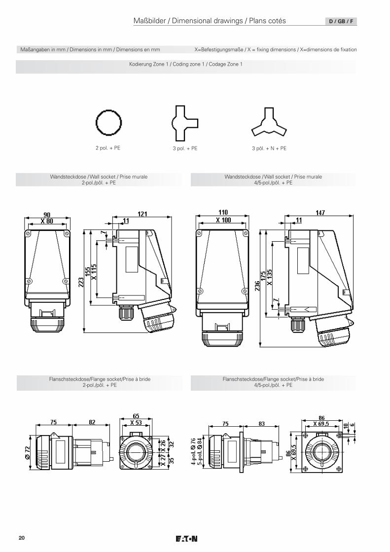
Maßbilder / Dimensional drawings / Plans cotés D / GB / F
Wandsteckdose / Wall socket / Prise murale 2-pol./pôl. + PE
Maßangaben in mm / Dimensions in mm / Dimensions en mm X=Befestigungsmaße / X = fixing dimensions / X=dimensions de fixation
2 pol. + PE 3 pol. + PE 3 pôl. + N + PE
Flanschsteckdose/Flange socket/Prise à bride 2-pol./pôl. + PE
Flanschsteckdose/Flange socket/Prise à bride 4/5-pol./pôl. + PE
Wandsteckdose / Wall socket / Prise murale 4/5-pol./pôl. + PE
Kodierung Zone 1 / Coding zone 1 / Codage Zone 1
21
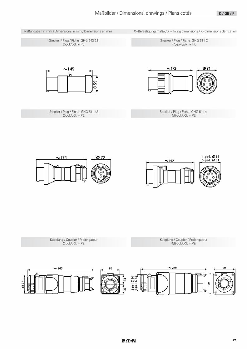
Maßbilder / Dimensional drawings / Plans cotés D / GB / F
Kupplung / Coupler / Prolongateur 4/5-pol./pôl. + PE
Stecker / Plug / Fiche GHG 543 23 2-pol./pôl. + PE
Stecker / Plug / Fiche GHG 531 7. 4/5-pol./pôl. + PE
Stecker / Plug / Fiche GHG 511 4. 4/5-pol./pôl. + PE
Stecker / Plug / Fiche GHG 511 43 2-pol./pôl. + PE
Kupplung / Coupler / Prolongateur 2-pol./pôl. + PE
Maßangaben in mm / Dimensions in mm / Dimensions en mm X=Befestigungsmaße / X = fixing dimensions / X=dimensions de fixation

22
Notizen / Notes / Remarques

23
Notizen / Notes / Remarques

Eaton is a registered trademark.
All trademarks are property of their respective owners.
Eaton is dedicated to ensuring that reliable, efficient and safe power is available when it’s needed most. With unparalleled knowledge of electrical power management across industries, experts at Eaton deliver customized, integrated solutions to solve our customers’ most critical challenges.
Our focus is on delivering the right solution for the appli-cation. But, decision makers demand more than just innovative products. They turn to Eaton for an unwavering commitment to personal support that makes customer success a top priority. For more information, visit
www.eaton.com/electrical.
Changes to the products, to the information contained in this document, and to prices are reserved; so are errors and omissions. Only order confirmations and technical documentation by Eaton is binding. Photos and pictures also do not warrant a specific layout or functionality. Their use in whatever form is subject to prior approval by Eaton. The same applies to Trademarks (especially Eaton, Moeller, and Cutler-Hammer). The Terms and Conditions of Eaton apply, as referenced on Eaton Internet pages and Eaton order confirmations.
Cooper Crouse-Hinds GmbHNeuer Weg-Nord 4969412 EberbachE-Mail: [email protected]
© 2018 EatonAll Rights ReservedPrinted in Germany
dd
Publication No. GHG 510 7001 P0001 D/GB/F (Q) / Auflage / 16.2018 / MS
CZ: "Tento návod k použití si m žete vyžádatve svém mate ském jazyce u p íslušnéhozastoupení spole nosti Cooper Crouse-Hinds/CEAG ve vaší zemi."
DK: "Montagevejledningen kan oversættes tilandre EU-sprog og rekvireres hos DeresCooper Crouse-Hinds/CEAG leverandør"
E: "En caso necesario podrá solicitar de surepresentante Cooper Crouse-Hinds/CEAGestas instrucciones de servicio en otro idiomade la Union Europea"
EST: "Seda kasutusjuhendit oma riigikeelesvõite küsida oma riigis asuvast asjaomasestCooper Crouse-Hindsi/CEAG esindusest."
FIN: "Tarvittaessa tämän käyttöohjeen käännöson saatavissa toisella EU:n kielellä TeidänCooper Crouse-Hinds/CEAG - edustajaltanne"
GR:
Cooper Crouse-Hinds/CEAG"
H: "A kezelési útmutatót az adott országnyelvén a Cooper Crouse-Hinds/CEAG céghelyi képviseletén igényelheti meg."
I: "Se desiderate la traduzione del manualeoperativo in un´altra lingua della Comunit àEuropea potete richiederla al vostrorappresentante Cooper Crouse-Hinds/CEAG"
LT: Šios naudojimo instrukcijos, išverstos J sugimt j kalb , galite pareikalauti atsakingoje"Cooper Crouse-Hinds/CEAG" atstovyb je savošalyje.
LV: "Šo ekspluat cijas instrukciju valsts valodvarat piepras t j su valsts atbild gaj CooperCrouse-Hinds/CEAG p rst vniec b ."
M: Jistg u jitolbu dan il-manwal fil-lingwanazzjonali tag hom ming and ir-rappre entantta' Cooper Crouse Hinds/CEAG f'pajji hom.
NL: "Indien noodzakelijk kan de vertaling vandeze gebruiksinstructie in een andere EU-taalworden opgevraagd bij Uw Cooper Crouse-Hinds/CEAG - vertegenwoordiging"
P: "Se for necessária a tradução destasinstruções de operação para outro idioma daUnião Europeia, pode solicita-la junto do seurepresentante Cooper Crouse-Hinds/CEAG"PL: Niniejsz instrukcj obs ugi w odpowiedniejwersji j zykowej mo na zamówi wprzedstawicielstwie firmy Cooper-Crouse-Hinds/CEAG na dany kraj.
S: "En översättning av denna montage- ochskötselinstruktion till annat EU - språk kan vidbehov beställas från Er Cooper Crouse-Hinds/CEAG- representant"
SK: "Tento návod na obsluhu Vám vo Vašomrodnom jazyku poskytne zastúpenie spolo nostiCooper Crouse-Hinds/CEAG vo Vašej krajine."
SLO: "Navodila za uporabo v Vašem jezikulahko zahtevate pri pristojnem zastopništvupodjetja Cooper Crouse-Hinds/CEAG v Vašidržavi."
RUS: "При необходимости, вы можете запрашивать перевод данного руководства на другом языке ЕС или на русском от вашего Cooper Crouse-Хиндс / CEAG - представителей."