
15K Installers Manual 6-3173 NOV07
46
OCT 2009 REV.- READ THIS INSTRUCTION MANUAL THOROUGHLY BEFORE INSTALLING, OPERATING, SERVICING OR MAINTAINING THE LIFT. SAVE THIS MANUAL. INSTALLATION and OPERATION MANUAL 6-3175 DLS15016 15,000 LB. (SYMMETRICAL)
Transcript of 15K Installers Manual 6-3173 NOV07
OCT 2009 REV.-
READ THIS INSTRUCTION MANUAL THOROUGHLY
BEFORE INSTALLING, OPERATING, SERVICING OR
MAINTAINING THE LIFT.
SAVE THIS MANUAL.
INSTALLATION
and OPERATION
MANUAL
6-3175
DLS15016
15,000 LB.
(SYMMETRICAL)
DLS15016
15,000 LB.
(SYMMETRICAL)
2
Table of Contents1.0 GENERAL ................................................................................................. 4
1.1 Owner/Employer Responsibilities .................................................. 42.0 Safety Precautions .................................................................................. 5
2.1 Use and Misuse of Lift ..................................................................... 62.2 General Warnings ............................................................................ 62.3 General Cautions ............................................................................. 7
3.0 SPECIFICATIONS .................................................................................... 93.1 Product Identification .................................................................... 10
4.0 PACKING LIST ....................................................................................... 104.1 Main Structural Components ........................................................ 104.2 Accessory Box ............................................................................... 10
5.0 INSTALLATION REQUIREMENTS AND TOOLS ....................................115.1 Foundation ......................................................................................115.2 Tools .................................................................................................11
6.0 INSTALLATION INSTRUCTION ............................................................. 126.1 Unpacking Procedure .................................................................... 126.2 Height Adjustment Procedure (if required) ................................. 136.3 Bay Layout ...................................................................................... 146.4 Tower Extension Bolting ............................................................... 156.5 Crossmember and Bracket Bolting .............................................. 156.6 Air Valve Installation and Bulk Head Fitting ................................ 166.7 Stand Towers Up ............................................................................ 176.8 Hydraulic Line Routing in Crossmember .................................... 176.9 Bolt Crossmember ......................................................................... 186.10 Connect Hydraulic Lines ............................................................. 196.11 Install Equalizing Cables and Adjusting .................................... 206.12 Level and Anchor Towers ............................................................ 226.13 Install Arms................................................................................... 256.14 Install Arm Restraints .................................................................. 266.15 Bolt Power Pack........................................................................... 266.16 Electrical Connection .................................................................. 276.17 Air Line Connection ..................................................................... 286.18 Hydraulic System Bleeding ......................................................... 296.19 Install Safety Cable ..................................................................... 306.20 Additional Instructions ................................................................ 316.21 Final Check of Assembled Lift .................................................... 326.22 Operation Test With Vehicle ........................................................ 33

3
7.0 Operation and Use ................................................................................ 347.1 Caution............................................................................................ 347.2 Lift Controls .................................................................................... 347.3 Lift Operation ................................................................................. 35
8.0 Maintenance .......................................................................................... 368.1 Equalization Cable Inspection ...................................................... 368.2 Inspection and Maintenance Procedures .................................... 378.3 Maintenance Schedule .................................................................. 38
9.0 Troubleshooting .................................................................................... 3910.0 Lift Assembly ....................................................................................... 40
10.1 Lift Assembly Parts List .............................................................. 4111.0 Hydraulic System ................................................................................ 42
11.1 Hydraulic System Parts List ........................................................ 4312.0 Safety System ...................................................................................... 44
12.1 Safety System Parts List ............................................................. 4513.0 Available Accessories ........................................................................ 46

4
1.0 GENERALAttention!
This is a vehicle lift operation manual and no attempt is made or implied herein to instruct theuser in lifting methods particular to an individual application. Rather, the contents of thismanual are intended as a basis for operation and maintenance of the unit as it stands aloneor as it is intended and anticipated to be used in conjunction with other equipment.
Proper application of the equipment described herein is limited to the parameters detailed inthe specifications and the uses set forth in the descriptive passages. The user assumes fullresponsibility for any equipment damage, personal injury or alteration of the equipmentdescribed in this manual or any subsequent damages.
WARNING:
Installation of equipment is hazardous. Only qualified personnel should perform installationprocedures. Installers should familiarize themselves with equipment and installation procedurebefore attempting installation.
Decommission and disposal of product must be performed in accordance with local, stateand/or federal regulations.
1.1 Owner/Employer Responsibilities
The Owner/Employer shall ensure that lift operators are qualified and that they are trainedin the safe use and operation of the lift using the manufacture’s operating instructions; ALI/SM 93-1, ALI SAFETY Tips card; ANSI/ALI ALOIM-1994, American National Standard forAutomotive Lifts-Safety Requirements for Operation, Inspection and Maintenance; ALI/WLSeries, ALI Uniform Warning Label Decals/Placards; and in the case of frame engaging lifts,ALI/LP-GUIDE, Vehicle Lifting Points/Quick Reference Guide for Frame Engaging Lifts.
The Owner/Employer shall establish procedures to periodically inspect the lift in accordancewith the lift manufacturer’s instructions or ANSI/ALI ALOIM-1994, American National Standardfor Automotive Lifts-Safety Requirements for Operation, Inspection and Maintenance; andthe employer shall ensure that lift inspectors are qualified and that they are adequately trainedin the inspection of the lift.
ATTENTION! THIS LIFT IS INTENDED FOR INDOOR INSTALLATIONONLY. IT IS PROHIBITED TO INSTALL THIS PRODUCT OUTDOORS.OPERATING ENVIRONMENT TEMPERATURE SHOULD BE 41 - 104 °F(5 - 40 °C). FAILURE TO ADHERE WILL RESULT INDECERTIFICATION, LOSS OF WARRANTY AND POSSIBLE DAMAGETO THE EQUIPMENT.

5
The Owner Employer shall establish procedures to periodically maintain the lift in accordancewith the lift manufacturer’s instructions or ANSI/ALI ALOIM-1994, American National Standardfor Automotive Lifts-Safety Requirements for Operation, Inspection and Maintenance; andthe employer shall ensure that lift maintenance personnel are qualified and that they areadequately trained in the maintenance of the lift.
The Owner/Employer shall maintain the periodic inspection and maintenance recordsrecommended by the manufacturer or ANSI/ALI ALOIM-1994, American National Standardfor Automotive Lifts-Safety Requirements for Operation, Inspection and Maintenance.
The Owner/Employer shall display the lift manufacturer’s operating instructions; ALI/SM93-1, ALI Lifting it Right safety manual; ALI/ST-90 ALI Safety Tips card; ANSI/ALI ALOIM-1994, American National Standard for Automotive Lifts-Safety Requirements for Operation,Inspection and Maintenance; and in the case of frame engaging lifts, ALI/LP-GUIDE, VehicleLifting Points/Quick Reference Guide for Frame Engaging Lifts in a conspicuous location inthe lift area convenient to the operator.
The Owner/Employer shall provide necessary lockout/tagout means for energy sources perANSI Z244.1-1982 (R1993), Safety Requirements for the Lockout/Tagout of Energy Sources,before beginning any lift repairs.
The Owner/Employer shall not modify the lift in any manner without prior written consent ofthe manufacturer.
2.0 SAFETY PRECAUTIONS
The lift is intended for use by properly trained personnel only.The safety messages presented in this manual are intended as reminders to trained
operators to exercise care when using the unit.
Read this Manual and the Safety Precautions thoroughly before operating the lift.

6
The lift has been designed for lifting vehicles and holding them at any height within the workingparameters of the machine in an enclosed environment.Any other use is forbidden including but not limited to:
The washing of vehiclesThe lifting of persons or use as scaffoldingExerting pressureLoading
2.2 General Warnings
Stay Clear of Area ifvehicle is in Danger ofFalling.
Avoid excessiverocking of vehicle whileon Lift.
Remain clear of lift whenraising or lowering vehicleand check for anyobstruction.
2.1 Use and Misuse of Lift
IMPORTANT WARNINGS:1. Do not operate the lift unless safety latches are functioning as evidenced by the safety
latches dropping into the safety ladder slots during the raising motion.
2. Do not operate the lift if the load tilts or binds during the up or down movement.
3. Always use all four arms when lifting a vehicle and follow the vehicle manufacturer’sguidelines for recommended lifting points.
Keep feet clear of liftwhile lowering.
Position vehicle withcenter of gravitymidway betweenadapters.
Do not make unauthorizedchanges and modificationsto the lift.
7
Do not use the lift above the rated load capacity of the lift (Pay attention toany additional load on the vehicle being lifted).
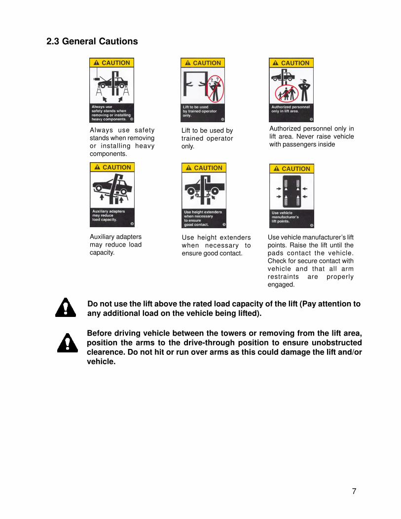
2.3 General Cautions
Always use safetystands when removingor installing heavycomponents.
Lift to be used bytrained operatoronly.
Authorized personnel only inlift area. Never raise vehiclewith passengers inside
Auxiliary adaptersmay reduce loadcapacity.
Use height extenderswhen necessary toensure good contact.
Use vehicle manufacturer’s liftpoints. Raise the lift until thepads contact the vehicle.Check for secure contact withvehicle and that all armrestraints are properlyengaged.
Before driving vehicle between the towers or removing from the lift area,position the arms to the drive-through position to ensure unobstructedclearence. Do not hit or run over arms as this could damage the lift and/orvehicle.
8
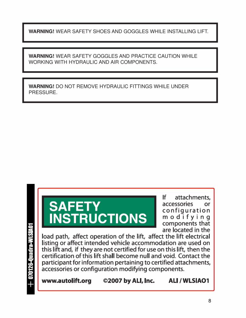
WARNING! WEAR SAFETY GOGGLES AND PRACTICE CAUTION WHILEWORKING WITH HYDRAULIC AND AIR COMPONENTS.
WARNING! WEAR SAFETY SHOES AND GOGGLES WHILE INSTALLING LIFT.
WARNING! DO NOT REMOVE HYDRAULIC FITTINGS WHILE UNDERPRESSURE.
9
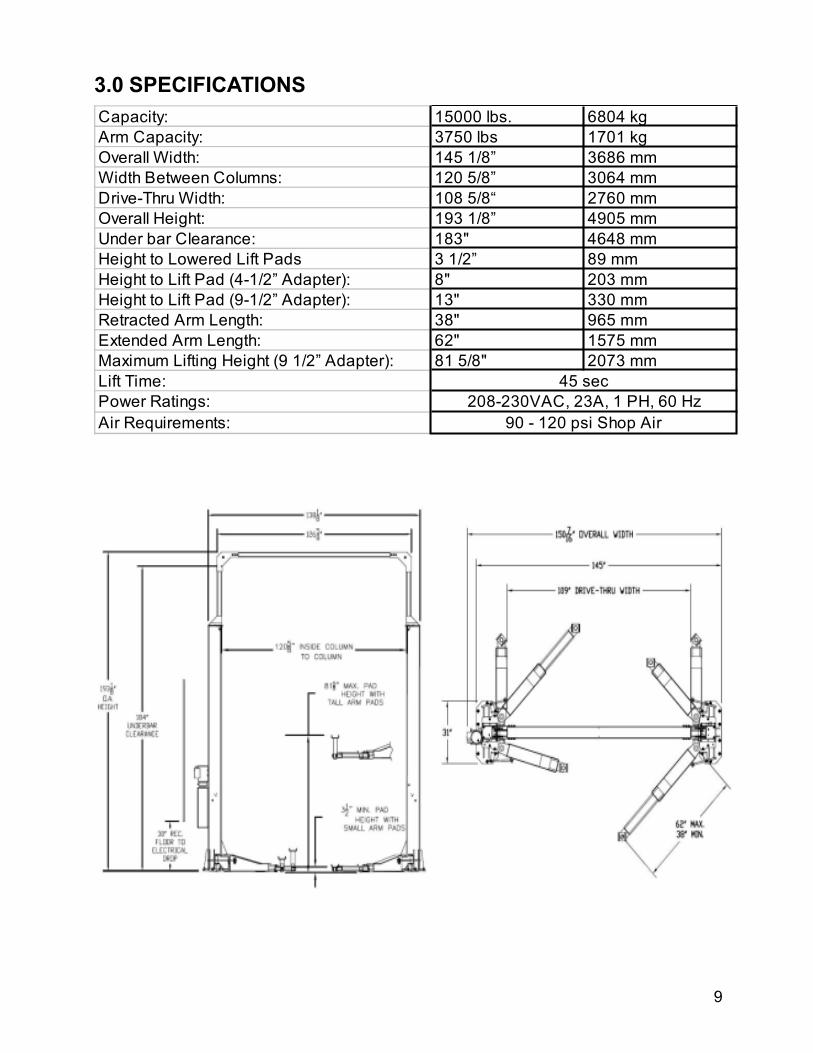
3.0 SPECIFICATIONS
Capacity: 15000 lbs. 6804 kg
Arm Capacity: 3750 lbs 1701 kg
Overall Width: 145 1/8” 3686 mm
Width Between Columns: 120 5/8” 3064 mm
Drive-Thru Width: 108 5/8“ 2760 mm
Overall Height: 193 1/8” 4905 mm
Under bar Clearance: 183" 4648 mm
Height to Lowered Lift Pads 3 1/2” 89 mm
Height to Lift Pad (4-1/2” Adapter): 8" 203 mm
Height to Lift Pad (9-1/2” Adapter): 13" 330 mm
Retracted Arm Length: 38" 965 mm
Extended Arm Length: 62" 1575 mm
Maximum Lifting Height (9 1/2” Adapter): 81 5/8" 2073 mm
Lift Time:
Power Ratings:
Air Requirements:
45 sec
208-230VAC, 23A, 1 PH, 60 Hz
90 - 120 psi Shop Air
10
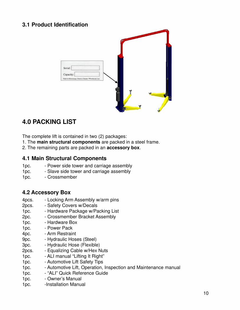
4.0 PACKING LIST
The complete lift is contained in two (2) packages:1. The main structural components are packed in a steel frame.2. The remaining parts are packed in an accessory box.
4.1 Main Structural Components1pc. - Power side tower and carriage assembly1pc. - Slave side tower and carriage assembly1pc. - Crossmember
4.2 Accessory Box4pcs. - Locking Arm Assembly w/arm pins2pcs. - Safety Covers w/Decals1pc. - Hardware Package w/Packing List2pc. - Crossmember Bracket Assembly1pc. - Hardware Box1pc. - Power Pack4pc. - Arm Restraint9pc. - Hydraulic Hoses (Steel)3pc. - Hydraulic Hose (Flexible)2pcs. - Equalizing Cable w/Hex Nuts1pc. - ALI manual “Lifting It Right”1pc. - Automotive Lift Safety Tips1pc. - Automotive Lift, Operation, Inspection and Maintenance manual1pc. - “ALI” Quick Reference Guide1pc. - Owner’s Manual1pc. -Installation Manual
3.1 Product Identification
11
5.0 INSTALLATION REQUIREMENTS AND TOOLS
5.1 FoundationIMPORTANT: It is the user’s responsibility to provide a satisfactory installation area for thelift. Lifts should only be installed on level concrete floors with a minimum thickness of five (5)inches or 130 mm. Concrete must have a minimum strength of 4000 psi or 30 MPa andshould be aged thirty (30) days prior to installation. Please consult the architect, contractor orengineer if doubt exists as to the strength and feasibility of the floor to enable proper liftinstallation and operation.
It is the user’s responsibility to provide all wiring for electrical hook-up prior to installation andto insure that the electrical installation conforms to local building codes. Where required, it isthe user’s responsibility to provide an electrical isolation switch located in close proximity tothe lift that will enable emergency stop capability and isolate electrical power from the lift forany servicing requirements.
5.2 Toolsa. Rotary hammer drill with ¾” solid drill bit with carbide tipb. Levelc. Hand Sledged. Pry Bare. Tape Measuref. Chalk lineg. 12’ Ladderh. Shortened 1 1/16" open-end Wrenchi. Vise Gripsj. Snap Ring Pliersk. 11/16" Open End Wrenchl. 5/8" Open End Wrenchm. 9/16" Socket and suitable ratchetn. 7/16" Socket and suitable ratcheto. 1/2” Socket and suitable ratchetp. 1 1/8" Deep Socket and suitable ratchetq. 4 Gal. Hydraulic fluid – Citgo A/W 46 or suitable cross-referencer. Overhead crane or Forklifts. Electrical Wire Fish.t. Wherever LOCTITE symbol is shown, apply LOCTITE #242 on required fasteners. If
fasteners are removed reapply LOCTITE before re-installing.
12
6.0 INSTALLATION INSTRUCTION
When the lift arrives on site:
• Read the owner’s manual thoroughly and make sure the installation instructions arefully understood before installing, operating, servicing, or maintaining the lift.
• Check for any freight damages.• Check the contents of the accessory and hardware boxes to make sure no parts are
missing.• Gather all the tools listed above.
6.1 Unpacking Procedure
6.1.1 Important! Place the main structural components on wooden blocks so that the steelshipping frames can be removed.
6.1.2 Remove the plastic wrapping.
6.1.3 Remove the crossmember.
6.1.4 Unbolt the steel shipping frames.
6.1.5 Lay each tower on the floor with the carriage side up.
6.1.6 Check the installation area for obstructions. (Lights, Heating Ducts, Ceiling, Floor Drains,etc.)
* A ceiling height of 195” or more is required to install this lift as it comes stock fromthe factory.
If cut down is required follow Section 6.2 - Height Adjustment Procedure.
Otherwise refer to Section 6.3 to begin installation.
NOTE: 20” is the maximum amount that the vertical profile can be lowered using theoriginal cables. If more than this amount is required, contact customer support1-800-225-5786 for assistance.

13
6.2 Height Adjustment Procedure (if required)
6.2.1 Vertical Profile Adjustment
To install vertical profiles in less than 195”, measure from floor to ceiling (or any obstacle such
as light fixtures, heaters, etc.) and subtract the minimum of 2” for crossmember clearance.
Next, subtract this measurement from 193”. This determines the distance the vertical profiles
are to be lowered. (See example below)
Example: Floor to ceiling measurement 190”
- 2”
188” (crossmember clearance)
Factory profile height 193”
- 188”
5” (Amount the vertical profile is to be
shortened)
Use a bandsaw or a reciprocating saw to cut down the calculated amount from the top of the
vertical profiles.
Using the vertical corner profile assembly as a template, redrill holes. The vertial profile is
now ready for installation.
6.2.2 Equalization Cable Adjustment
If the vertical profiles have been shortened, the equalization cables will also need shortening.
This is done by shortening the long threaded rod on both cables.
To determine the amount of threaded rod to be cut off, double the amount calculated for the
vertical profile cut down.
Example: If the vertical profile was cut down by 5”, the threaded rod on the equalization
cables must be shortened by 10”.
6.2.3 Hydraulic Tube AdjustmentI
f the vertical profiles have been shortened, the vertical profile hydraulic tubes must also be
shortened. This procedure must be completed using a tube cutter. DO NOT use a hacksaw.
Each tube that is cut must be flushed wih cleaning fluid to prevent debris from entering the
hydraulic cylinders and pump.The cut ends must be re-flared with a flaring tool.
Example: If the vertical profile was cut down by 5”, the hydraulic tubes must also be
shortened by 5”.
14
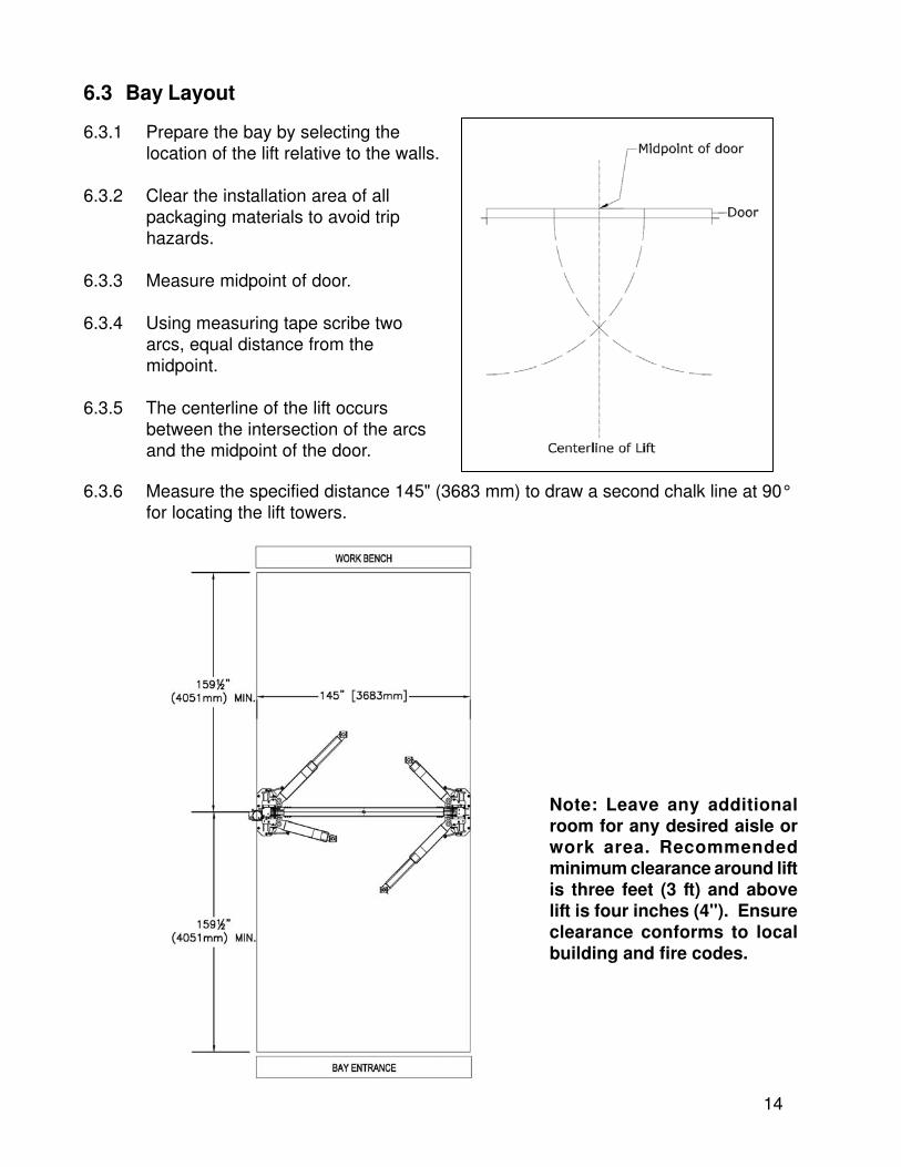
6.3 Bay Layout
6.3.1 Prepare the bay by selecting thelocation of the lift relative to the walls.
6.3.2 Clear the installation area of allpackaging materials to avoid triphazards.
6.3.3 Measure midpoint of door.
6.3.4 Using measuring tape scribe twoarcs, equal distance from themidpoint.
6.3.5 The centerline of the lift occursbetween the intersection of the arcsand the midpoint of the door.
6.3.6 Measure the specified distance 145" (3683 mm) to draw a second chalk line at 90°for locating the lift towers.
Note: Leave any additionalroom for any desired aisle orwork area. Recommendedminimum clearance around liftis three feet (3 ft) and abovelift is four inches (4"). Ensureclearance conforms to localbuilding and fire codes.
15
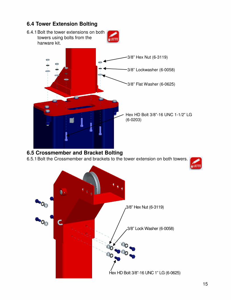
6.4 Tower Extension Bolting
6.4.1Bolt the tower extensions on bothtowers using bolts from theharware kit.
6.5 Crossmember and Bracket Bolting6.5.1Bolt the Crossmember and brackets to the tower extension on both towers.
Hex HD Bolt 3/8”-16 UNC 1-1/2” LG(6-0203)
3/8” Flat Washer (6-0625)
3/8” Lockwasher (6-0058)
3/8” Hex Nut (6-3119)
Hex HD Bolt 3/8”-16 UNC 1” LG (6-0625)
3/8” Lock Washer (6-0058)
3/8” Hex Nut (6-3119)

16
6.6 Air Valve Installation and Bulk Head Fitting
6.6.2Attach the Tee fitting to the Air Valve.
Air Valve (6-3136)
Male Run’g Tee 5/32”-5/32”-1/8” (6-3132)
6.6.3 Insert two nuts on the Air Valve.Nut
6.6.4Attach the Air Valve assembly to the driver sidetower using two more nuts provided.
6.6.1Remove air valve push button.
Insert Air Valve assembly in small hole next to the studs6.6.5 Screw air Valve Push button.
6.6.6Attach the bulk head fitting to thetower extension and insert the Malepushlock fitting.
Bulk Head Fitting
Male Elbow ¼” – ¼” NPT
17
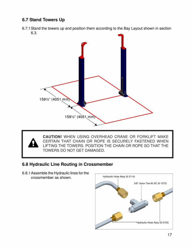
6.8 Hydraulic Line Routing in Crossmember
6.8.1Assemble the Hydraulic lines for thecrossmember as shown. Hydraulic Hose Assy (6-3114)
Hydraulic Hose Assy (6-3152)
3/8” Union Tee M JIC (6-1372)
6.7 Stand Towers Up
6.7.1Stand the towers up and position them according to the Bay Layout shown in section6.3.
159½” (4051 mm)159½” (4051 mm)
159½” (4051 mm)159½” (4051 mm)
CAUTION! WHEN USING OVERHEAD CRANE OR FORKLIFT MAKECERTAIN THAT CHAIN OR ROPE IS SECURELY FASTENED WHENLIFTING THE TOWERS. POSITION THE CHAIN OR ROPE SO THAT THETOWERS DO NOT GET DAMAGED.
18
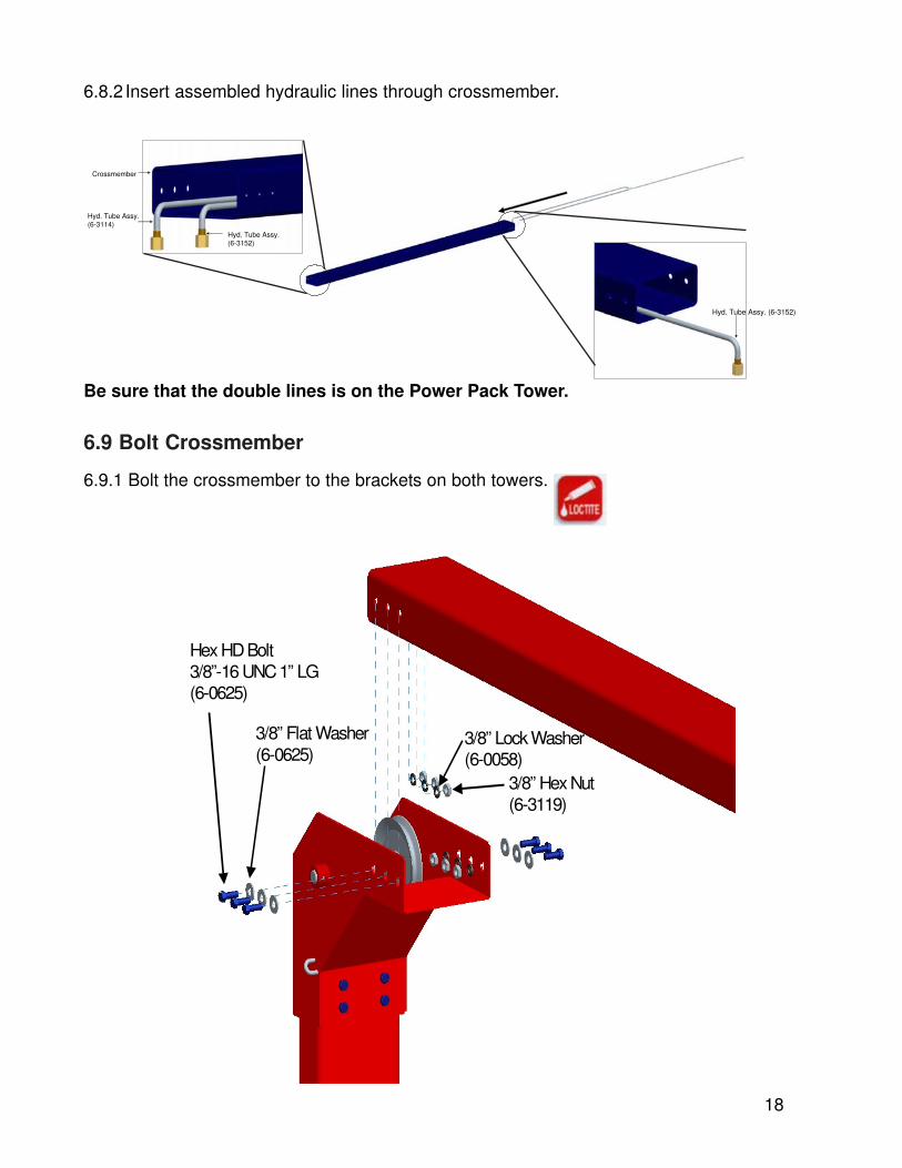
6.8.2 Insert assembled hydraulic lines through crossmember.
Be sure that the double lines is on the Power Pack Tower.
Crossmember
Hyd. Tube Assy.(6-3114)
Hyd. Tube Assy.(6-3152)
Hyd. Tube Assy. (6-3152)
6.9 Bolt Crossmember
6.9.1 Bolt the crossmember to the brackets on both towers.
Hex HD Bolt3/8”-16 UNC 1” LG(6-0625)
3/8” Lock Washer (6-0058)
3/8” Hex Nut (6-3119)
3/8” Flat Washer (6-0625)
19
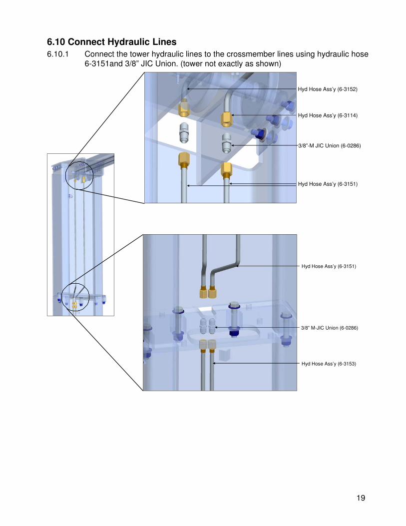
6.10 Connect Hydraulic Lines6.10.1 Connect the tower hydraulic lines to the crossmember lines using hydraulic hose
6-3151and 3/8” JIC Union. (tower not exactly as shown)
3/8”-M JIC Union (6-0286)
Hyd Hose Ass’y (6-3151)
Hyd Hose Ass’y (6-3114)
Hyd Hose Ass’y (6-3152)
Hyd Hose Ass’y (6-3151)
3/8” M-JIC Union (6-0286)
Hyd Hose Ass’y (6-3153)
20
6.11 Install Equalizing Cables and Adjusting
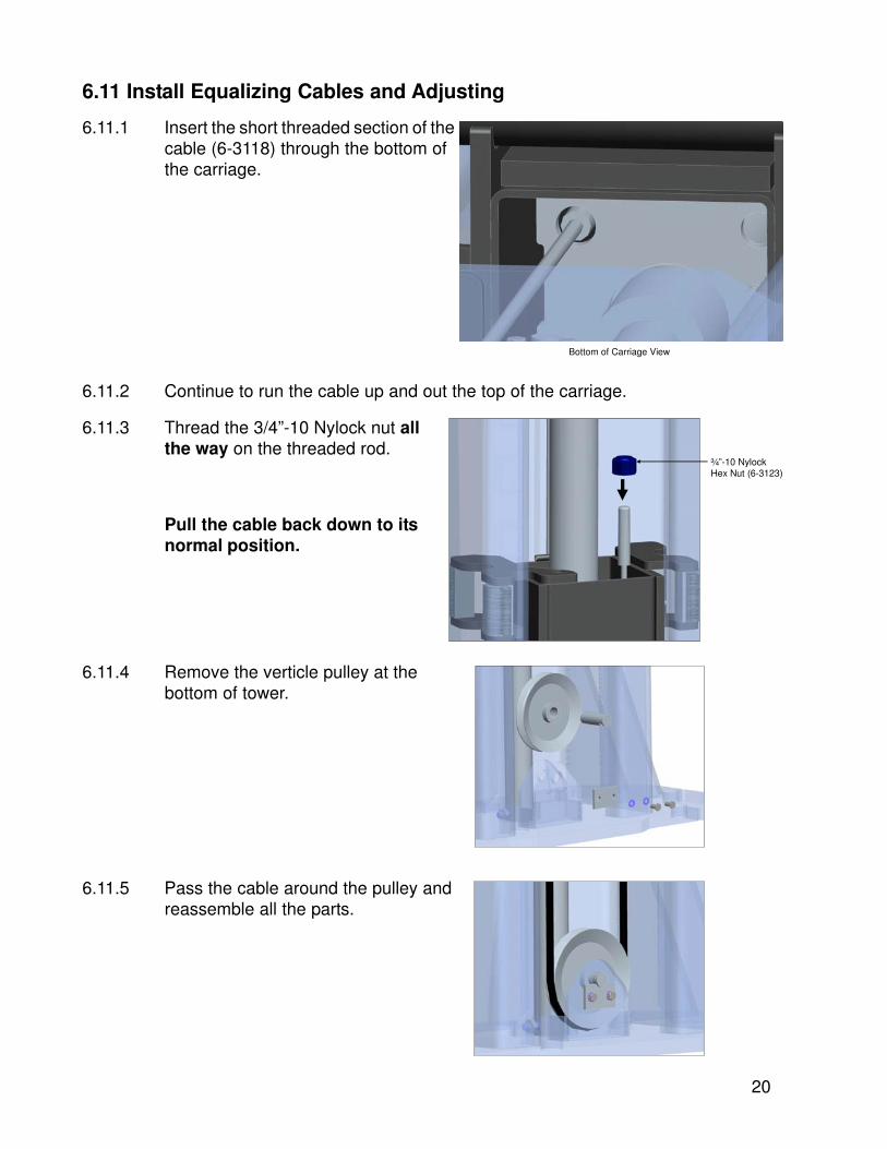
6.11.1 Insert the short threaded section of thecable (6-3118) through the bottom ofthe carriage.
6.11.2 Continue to run the cable up and out the top of the carriage.
6.11.3 Thread the 3/4”-10 Nylock nut allthe way on the threaded rod.
¾”-10 NylockHex Nut (6-3123)
6.11.4 Remove the verticle pulley at thebottom of tower.
6.11.5 Pass the cable around the pulley andreassemble all the parts.
Pull the cable back down to itsnormal position.
Bottom of Carriage View
21
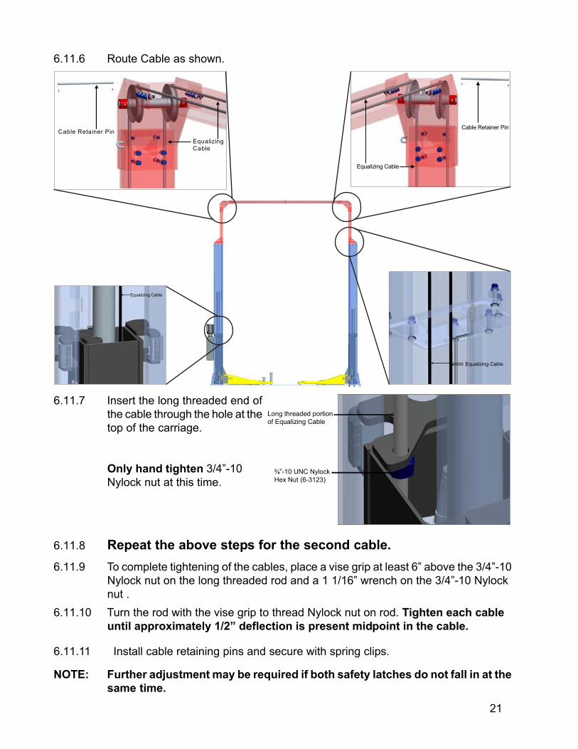
6.11.6 Route Cable as shown.
Equalizing
Cable
Cable Retainer Pin
Equalizing Cable
Cable Retainer Pin
Equalizing Cable
Equalizing Cable
6.11.7 Insert the long threaded end of
the cable through the hole at the
top of the carriage.
Only hand tighten 3/4”-10
Nylock nut at this time.
Long threaded portion
of Equalizing Cable
¾”-10 UNC Nylock
Hex Nut (6-3123)
6.11.8 Repeat the above steps for the second cable.
6.11.9 To complete tightening of the cables, place a vise grip at least 6” above the 3/4”-10
Nylock nut on the long threaded rod and a 1 1/16” wrench on the 3/4”-10 Nylock
nut .
6.11.10 Turn the rod with the vise grip to thread Nylock nut on rod. Tighten each cable
until approximately 1/2” deflection is present midpoint in the cable.
NOTE: Further adjustment may be required if both safety latches do not fall in at the
same time.
6.11.11 Install cable retaining pins and secure with spring clips.
22
6.12 Level and Anchor Towers
WARNING! Failure to follow these instructions may cause an unsafeoperating condition.
6.12.1 Determine which tower is higher using a level.
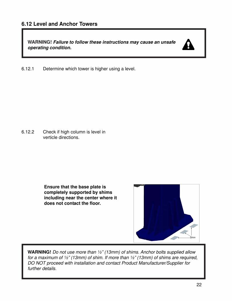
6.12.2 Check if high column is level inverticle directions.
Shim
Ensure that the base plate iscompletely supported by shimsincluding near the center where itdoes not contact the floor.
WARNING! Do not use more than ½” (13mm) of shims. Anchor bolts supplied allowfor a maximum of ½” (13mm) of shim. If more than ½” (13mm) of shims are required,DO NOT proceed with installation and contact Product Manufacturer/Supplier forfurther details.

23
6.12.3 Refer to Bay Layout to ensure that the column is still in the proper position.
6.12.4 Drill ¾” holes using a hammerdrill for the anchor bolts on thehigh side column.
DrillDrill
6.12.5 Clean out the drilling dust from the holes. Assemble the nut and washer ontoanchors. A minimum of six threads must be visible below the surface of the nut. Hammer inthe anchor bolts until they contact baseplate. Hand tighten all anchor bolts.
Note: Leave any additionalroom for any desired aisle orwork area. Recommendedminimum clearance aroundand the lift is three feet (3 ft)and above the lift is fourinches (4”). Ensure clearanceconforms to local building andfire codes.

24
Note: Check that the column is level front to rear and side to side. Adjust shimsas required.
6.12.7 Torque all anchor bolts to 150 ft-lbs.(203 Nm), continually checking that thecolumn is level as you proceed.
6.12.6 Check the distance from the top of the anchor to the floor. If this dimension exceeds2¼” due to floor slope, DO NOT use the supplied anchors.
Note: The 3/4" ××××× 5 ½” lg. wedge anchorbolts supplied must have a minimumembedment of 3¼” into concrete floor.
25
6.13 Install Arms
If anchor bolts do not tighten to 150 ft-lbs. OR project more than 2¼” above theconcrete surface due to floor slope, the concrete should be replaced by anappropriate concrete pad. (Consult Product Manufacturer / Supplier for furtherdetails).
6.12.8 Repeat above steps (6.12.2-6.12.7) to anchor the second tower.
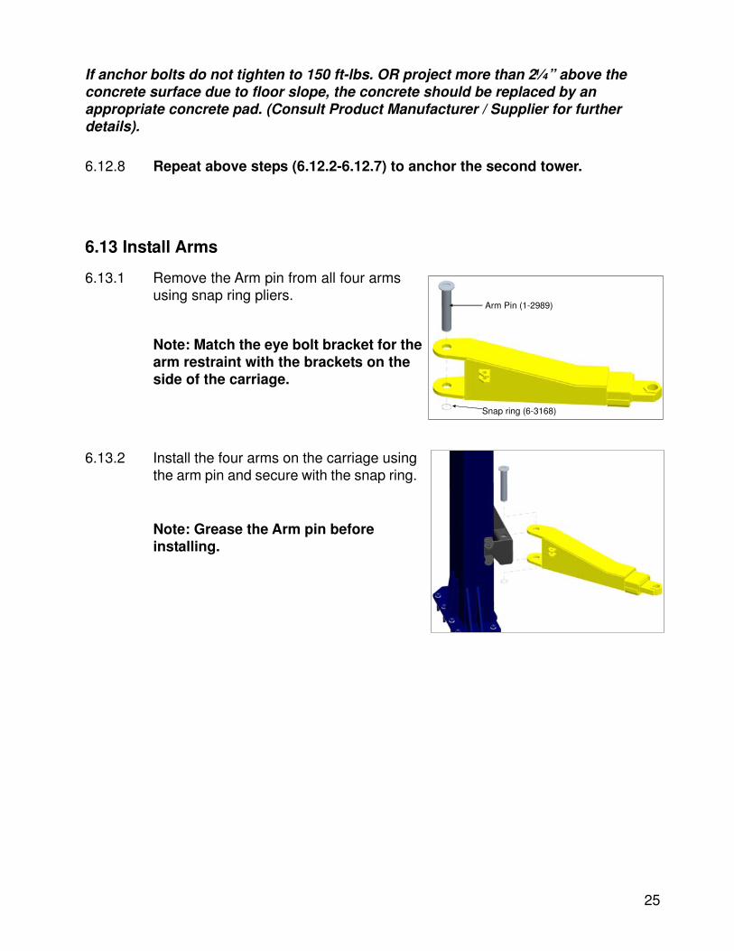
6.13.1 Remove the Arm pin from all four armsusing snap ring pliers.
Arm Pin (1-2989)
Snap ring (6-3168)
6.13.2 Install the four arms on the carriage usingthe arm pin and secure with the snap ring.
Note: Match the eye bolt bracket for thearm restraint with the brackets on theside of the carriage.
Note: Grease the Arm pin beforeinstalling.
26
6.15 Bolt Power Pack
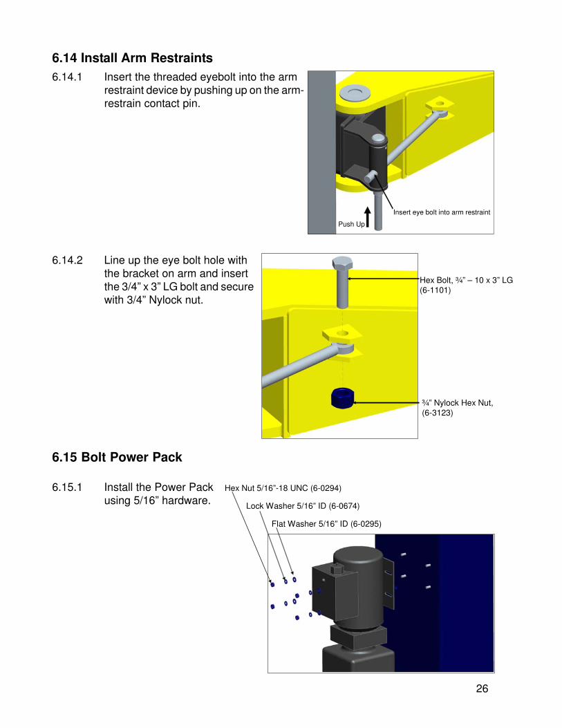
6.14 Install Arm Restraints6.14.1 Insert the threaded eyebolt into the arm
restraint device by pushing up on the arm-restrain contact pin.
Insert eye bolt into arm restraint
Push Up
6.14.2 Line up the eye bolt hole withthe bracket on arm and insertthe 3/4” x 3” LG bolt and securewith 3/4” Nylock nut.
Hex Bolt, ¾” – 10 x 3” LG (6-1101)
¾” Nylock Hex Nut, (6-3123)
Flat Washer 5/16” ID (6-0295)
Lock Washer 5/16” ID (6-0674)
Hex Nut 5/16”-18 UNC (6-0294)6.15.1 Install the Power Packusing 5/16” hardware.
27
6.16 Electrical Connection
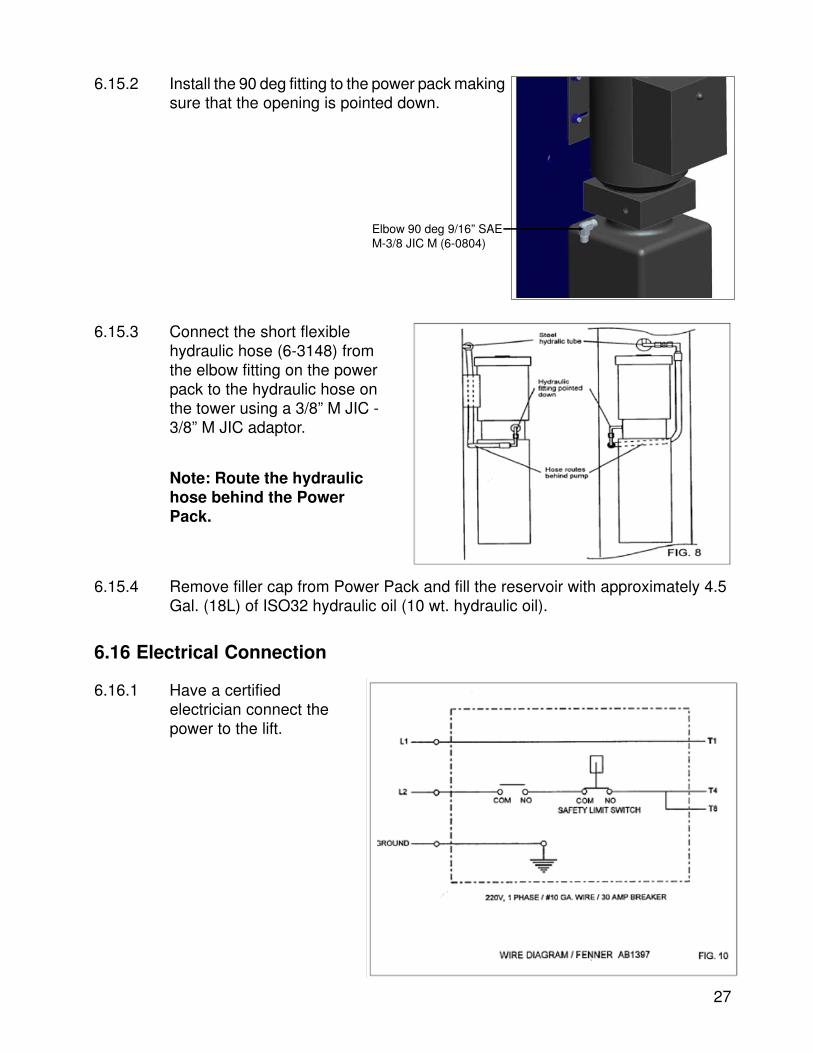
Elbow 90 deg 9/16” SAE M-3/8 JIC M (6-0804)
6.15.2 Install the 90 deg fitting to the power pack makingsure that the opening is pointed down.
6.15.3 Connect the short flexiblehydraulic hose (6-3148) fromthe elbow fitting on the powerpack to the hydraulic hose onthe tower using a 3/8” M JIC -3/8” M JIC adaptor.
Note: Route the hydraulichose behind the PowerPack.
6.15.4 Remove filler cap from Power Pack and fill the reservoir with approximately 4.5Gal. (18L) of ISO32 hydraulic oil (10 wt. hydraulic oil).
6.16.1 Have a certifiedelectrician connect thepower to the lift.
28
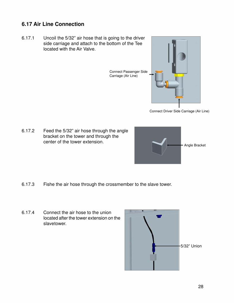
Connect Driver Side Carriage (Air Line)
Connect Passenger Side Carriage (Air Line)
6.17 Air Line Connection
6.17.1 Uncoil the 5/32” air hose that is going to the driverside carriage and attach to the bottom of the Teelocated with the Air Valve.
6.17.2 Feed the 5/32” air hose through the anglebracket on the tower and through thecenter of the tower extension.
6.17.3 Fishe the air hose through the crossmember to the slave tower.
6.17.4 Connect the air hose to the unionlocated after the tower extension on theslavetower.
Angle Bracket
5/32” Union

29
¼” JIC Cap (6-1884)
1/8” NPT to ¼” NPT (6-0280)
6.18 Hydraulic System Bleeding
6.18.1 Crack the caps located at the top of bothcylinders.
6.18.2 Power up 2”-3”. You should hear airescaping around the caps. Repeat 3-4times or until only oil is coming out ofthe caps.
6.18.3 Tighten the caps and lower the lift.
6.18.4 Be sure that all other hydraulic fittings are tight.
30
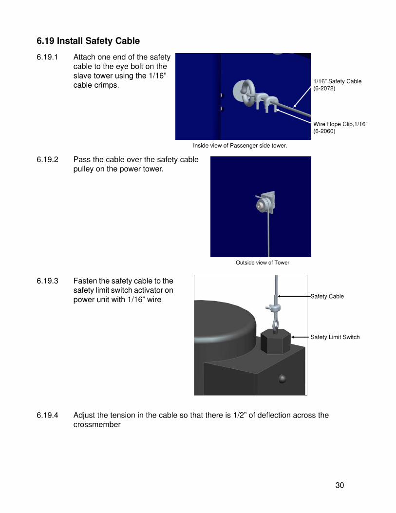
6.19 Install Safety Cable
6.19.1 Attach one end of the safetycable to the eye bolt on theslave tower using the 1/16”cable crimps. 1/16” Safety Cable
(6-2072)
Wire Rope Clip,1/16”(6-2060)
Inside view of Passenger side tower.
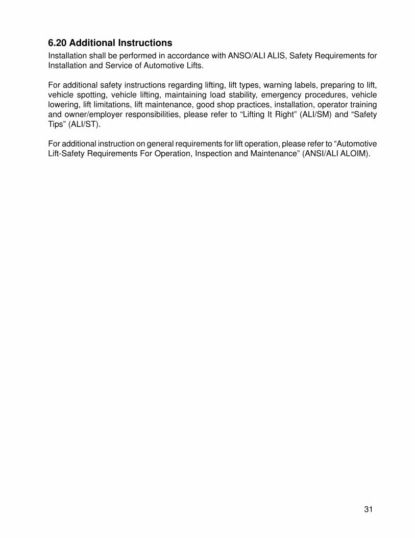
6.19.2 Pass the cable over the safety cablepulley on the power tower.
Outside view of Tower
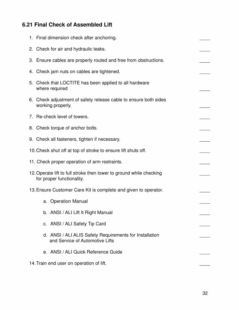
6.19.3 Fasten the safety cable to thesafety limit switch activator onpower unit with 1/16” wire
Safety Limit Switch
Safety Cable
6.19.4 Adjust the tension in the cable so that there is 1/2” of deflection across thecrossmember
31
6.20 Additional InstructionsInstallation shall be performed in accordance with ANSO/ALI ALIS, Safety Requirements forInstallation and Service of Automotive Lifts.
For additional safety instructions regarding lifting, lift types, warning labels, preparing to lift,vehicle spotting, vehicle lifting, maintaining load stability, emergency procedures, vehiclelowering, lift limitations, lift maintenance, good shop practices, installation, operator trainingand owner/employer responsibilities, please refer to “Lifting It Right” (ALI/SM) and “SafetyTips” (ALI/ST).
For additional instruction on general requirements for lift operation, please refer to “AutomotiveLift-Safety Requirements For Operation, Inspection and Maintenance” (ANSI/ALI ALOIM).
32
6.21 Final Check of Assembled Lift
1. Final dimension check after anchoring. ____
2. Check for air and hydraulic leaks. ____
3. Ensure cables are properly routed and free from obstructions. ____
4. Check jam nuts on cables are tightened. ____
5. Check that LOCTITE has been applied to all hardwarewhere required ____
6. Check adjustment of safety release cable to ensure both sidesworking properly. ____
7. Re-check level of towers. ____
8. Check torque of anchor bolts. ____
9. Check all fasteners, tighten if necessary. ____
10.Check shut off at top of stroke to ensure lift shuts off. ____
11. Check proper operation of arm restraints. ____
12.Operate lift to full stroke then lower to ground while checking ____for proper functionality.
13.Ensure Customer Care Kit is complete and given to operator. ____
a. Operation Manual ____
b. ANSI / ALI Lift It Right Manual ____
c. ANSI / ALI Safety Tip Card ____
d. ANSI / ALI ALIS Safety Requirements for Installation ____ and Service of Automotive Lifts
e. ANSI / ALI Quick Reference Guide ____
14.Train end user on operation of lift. ____
33
6.22 Operation Test With Vehicle
1. Lower lift to the ground. ____
2. Drive vehicle on to lift and locate the arms as per the “Lift it Right” manual. ____
3. Raise lift to and lower onto 3-4 lock positions during full rise to ensureall locks are working correctly. ____
4. Re-adjust cables if necessary while vehicle is on. ____
5. Check lowering speed and smooth decent rate. ____
6. Lower lift to the ground and drive vehicle off lift. ____
If any problems occur during the final checkout or operation of the lift please contactcustomer service at 1-800-225-5786.
34
7.0 OPERATION AND USE
1. Do not exceed maximum rated lift capacity.
2. Only trained and authorized personnel should operate this lift. Read, understandand follow all literature supplied with the lift.
3. Make certain lift area is clear of all personnel during lift operations.
4. Always watch the lift during operation.
7.1 Caution
SPECIAL INSTRUCTIONS for long wheelbase vehicles such as limousines, cargo vans,light trucks with toolboxes, extended and dual cab light trucks, etc.
1. Do not lift without finding the vehicles center of gravity.
2. Do not exceed the stated capacity of the lift.
3. Do not operate the lift if the load is not stable.
4. Observe overhead clearance for obstructions when lifting light trucks with ladder racks,cranes, campers, etc.
5. Always use all four arms when lifting a vehicle and follow the vehicle manufacturersguidelines for recommended lifting points.
6. Height extenders may be needed for proper frame engagement when lifting light trucksand vans.
7. Do not use wood, bricks, homemade extenders, etc.
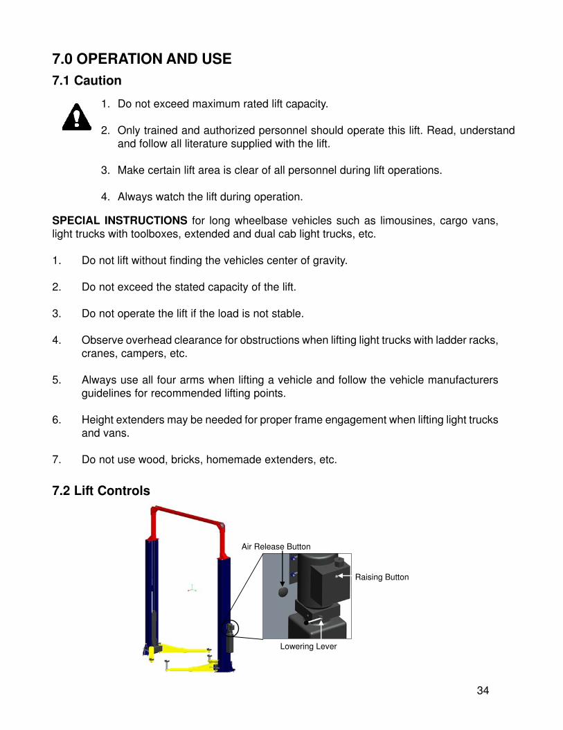
Air Release Button
Lowering Lever
Raising Button
7.2 Lift Controls
35
7.3 Lift Operation
To Lower Vehicles:
1. Clear area around and under the lift of obstructions and warn personnel to stand clear.
2. Raise vehicle slightly to remove pressure on the safety latches.
3. Depress air valve and pull release lever on pump.
4. No one must be under the vehicle when lowering as the safeties are released.
5. Lower the lift until arms have bottomed and are clear of the lifting points.
6. Swing the lifting arms from beneath the vehicle and fully retract the arms.
7. Remove the vehicle.
To Raise Vehicles:
1. Read and understand all safety and operation labels on the lift.
2. Position arms to drive-thru position.
3. Refer to supplied literature prior to loading. Center the vehicle between the lift posts.
4. Only lift the vehicle on the manufacturer’s recommended lift points. Refer to the suppliedlift points guide.
5. Locate lift pads on auto manufacture’s recommended lift points. Once you have correctlypositioned the lift arm ensure that all arm restraints are properly engaged.
6. Raise the vehicle by pushing the up button on the power pack. Once the desired workingheight is reached lower onto the mechanical safety using the lowering lever.
36
8.1 Equalization Cable Inspection
Without load, raise the lift in increments that will allow inspection of the entire cable. If thefollowing conditions exist replace the cable:
1. When its diameter is less than 11/32".
2. If 3 or more element wires are broken in a single strand.
3. If 6 or more element wires are broken in a strand lay.
4. Cable is badly deformed or rusted.
5. Broken wires at the connection to threaded rods.
Inspect the lower column and crossmember pulleys for excessive wear in the groove, bushingor axle.
Lubricate the entire cable with light oil annually.
Guidelines to be followed for proper lift maintenance include:Always use genuine spare parts.Always use tools and equipment suitable for the work to be carried out.Follow the scheduled maintenance and check periods shown in this manual.
Refer to manufacturers documentation:Exploded views for ordering of replacement parts.The trouble shooting guide contained in this manual.
8.0 MAINTENANCE
Only trained personnel who are familiar with the equipment should beallowed to service the lift.
All Maintenance other than the routine tasks outlined below must becarried out by the manufacturer/supplier.
Before starting any maintenance or repairs to the lift make sure the mainpower switch is locked.

37
8.2 Inspection and Maintenance Procedures
The schedule is based on conditions found in the usual automotive service environmentunder normal usage (approximately 1200 cycles per year). In cases of high volume operationor areas with a high density of airborne debris, the schedule must be accelerated.
DAILY:
1. Check all hydraulic lines and fittings for pinch points, damage, cracks or leaks.2. Check all electrical wiring for pinch points, cracks or damage.3. Check all moving parts for uneven or excessive wear.4. Repair or replace all damaged, defective, worn or broken components immediately.5. Check the telescopic arms for movement. Clean any grease or oil from the lifting adapters.6. Raise and lower the lift at the beginning of each shift (without a vehicle on) to verify the
lift is leveled and operating properly.
EVERY TWO MONTHS:
1. Check the arm restraint rods be sure to keep threads clean and rust free.2. Clean and re-grease slide block channels inside of both columns.3. Grease arm pins.
EVERY FOUR MONTHS:
1. Column anchor bolts and re-torque to 150 ft. lbs if required. If unable to tighten suspenduse of lift and contact manufacturer.
2. Lubricate cable pulleys.3. Check equalizing cable adjustment. (see section 6.1)
EVERY SIX MONTHS:
1. Inspect carriage bearings, grease with lithium RP #2. Replace bearings when clearancebetween bearing mounting plates and column is less than 1/16”.
EVERY YEAR:
1. Inspect lift as per Automotive Lift Operation, Inspection and Maintenance (ALOIM).
EVERY TWO YEARS:
1. Change hydraulic fluid with CITGO AW 46 or equal.
CAUTION
Always check for floor cracks emulating from under the columns, structural wear or ifthe lift is visually out of plumb. Contact the manufacturer for assistance.
38
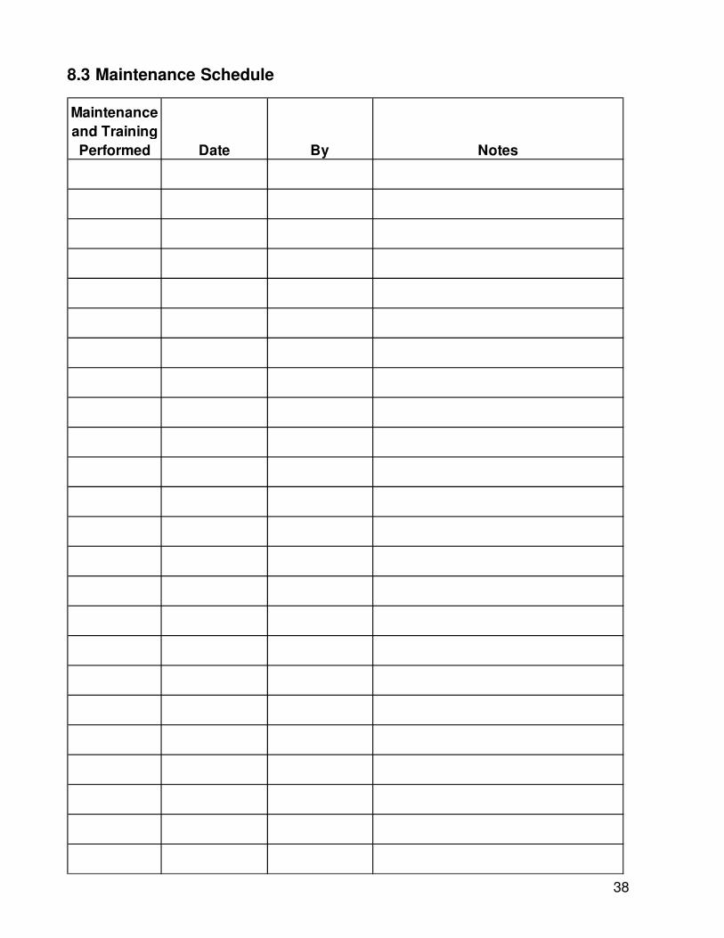
8.3 Maintenance Schedule
Maintenance and Training Performed Date By Notes
39
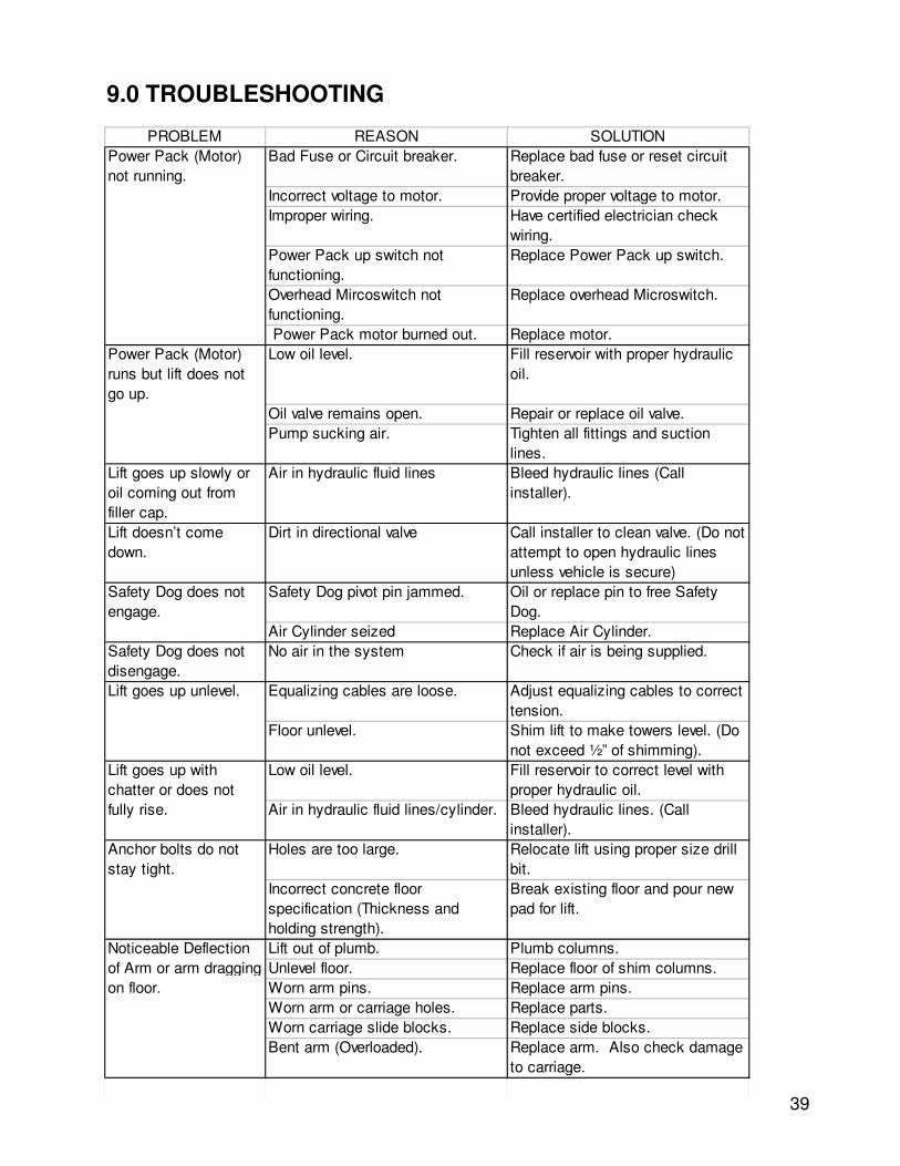
9.0 TROUBLESHOOTING
PROBLEM REASON SOLUTIONBad Fuse or Circuit breaker. Replace bad fuse or reset circuit
breaker.Incorrect voltage to motor. Provide proper voltage to motor.Improper wiring. Have certified electrician check
wiring.Power Pack up switch not functioning.
Replace Power Pack up switch.
Overhead Mircoswitch not functioning.
Replace overhead Microswitch.
Power Pack motor burned out. Replace motor.Low oil level. Fill reservoir with proper hydraulic
oil.
Oil valve remains open. Repair or replace oil valve.Pump sucking air. Tighten all fittings and suction
lines.Lift goes up slowly or oil coming out from filler cap.
Air in hydraulic fluid lines Bleed hydraulic lines (Call installer).
Lift doesn’t come down.
Dirt in directional valve Call installer to clean valve. (Do not attempt to open hydraulic lines unless vehicle is secure)
Safety Dog pivot pin jammed. Oil or replace pin to free Safety Dog.
Air Cylinder seized Replace Air Cylinder.Safety Dog does not disengage.
No air in the system Check if air is being supplied.
Equalizing cables are loose. Adjust equalizing cables to correct tension.
Floor unlevel. Shim lift to make towers level. (Do not exceed ½” of shimming).
Low oil level. Fill reservoir to correct level with proper hydraulic oil.
Air in hydraulic fluid lines/cylinder. Bleed hydraulic lines. (Call installer).
Holes are too large. Relocate lift using proper size drill bit.
Incorrect concrete floor specification (Thickness and holding strength).
Break existing floor and pour new pad for lift.
Lift out of plumb. Plumb columns.Unlevel floor. Replace floor of shim columns.Worn arm pins. Replace arm pins.Worn arm or carriage holes. Replace parts.Worn carriage slide blocks. Replace side blocks.Bent arm (Overloaded). Replace arm. Also check damage
to carriage.
Lift goes up with chatter or does not fully rise.
Anchor bolts do not stay tight.
Noticeable Deflection of Arm or arm dragging on floor.
Power Pack (Motor) not running.
Power Pack (Motor) runs but lift does not go up.
Safety Dog does not engage.
Lift goes up unlevel.
40
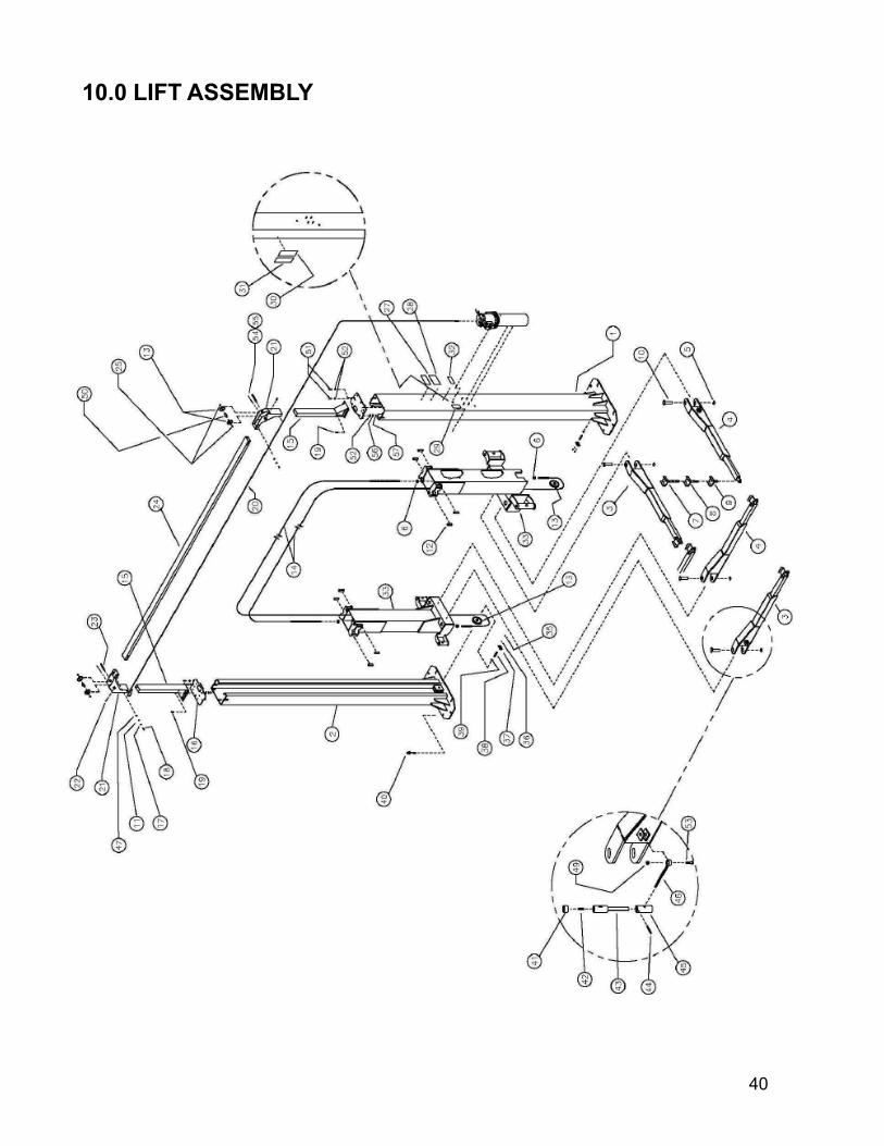
10.0 LIFT ASSEMBLY
41
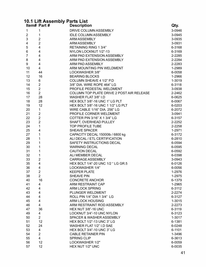
10.1 Lift Assembly Parts ListItem# Part # Description Qty.
1 1 DRIVE COLUMN ASSEMBLY 3-0946
2 1 IDLE COLUMN ASSEMBLY 3-0945
3 2 ARM ASSEMBLY 3-0935
4 2 ARM ASSEMBLY 3-0931
5 4 RETAINING RING 1 3/4” 6-3168
6 4 NYLON LOCKNUT 1/2”-13 6-3169
7 4 ARM PAD EXTENSION ASSEMBLY 2-2285
8 4 ARM PAD EXTENSION ASSEMBLY 2-2284
9 4 ARM PAD ASSEMBLY 2-2283
10 4 ARM MOUNTING PIN WELDMENT 1-2989
11 44 LOCKWASHER 3/8” 6-0058
12 16 BEARING BLOCKS 1-2966
13 6 COLUMN SHEAVE 4 1/2” P.D 1-3019
14 2 3/8” DIA. WIRE ROPE 464” LG 6-3118
15 2 PROFILE PEDESTAL WELDMENT 3-0938
16 2 COLUMN TOP PLATE DRIVE 2 POST AIR RELEASE 2-2462
17 28 WASHER FLAT 3/8” I.D 6-0625
18 28 HEX BOLT 3/8”-16 UNC 1” LG PLT 6-0067
19 12 HEX BOLT 3/8”-16 UNC 1 1/2” LG PLT 6-0203
20 1 WIRE CABLE 1/16” DIA. 256” LG 6-2072
21 2 PROFILE CORNER WELDMENT 3-0941
22 2 COTTER PIN 3/16” X 1 3/4” LG 6-3157
23 2 SHAFT, OVERHEAD PULLEY 2-2252
24 1 TOP PROFILE TUBE 2-2258
25 4 SHEAVE SPACER 1-2971
27 1 CAPACITY DECAL 15000lb / 6800 kg 6-3172
28 1 ALI DECAL / ETL CERTIFICATION 6-2810
29 1 SAFETY INSTRUCTIONS DECAL 6-0594
30 1 WARNING DECAL 6-0595
31 1 CAUTION DECAL 6-0592
32 1 ALI MEMBER DECAL 6-0398
33 2 CARRIAGE ASSEMBLY 3-0943
35 4 HEX BOLT 1/4”-20 UNC 1/2 “ LG GR.5 6-0126
36 4 LOCKWASHER 1/4” 6-0056
37 2 KEEPER PLATE 1-2976
38 2 SHEAVE PIN 1-2975
40 16 CONCRETE ANCHOR 6-1379
41 4 ARM RESTRAINT CAP 1-2965
42 4 ARM LOCK SPRING 6-3112
43 4 PLUNGER WELDMENT 2-2274
44 4 ROLL PIN 1/4” DIA 1 3/4” LG 6-3127
45 4 ARM LOCK HOUSING 1-3015
46 4 ARM RESTRAINT ROD ASSEMBLY 2-2273
47 36 HEX NUT 3/8”-16 UNC 6-3119
49 4 LOCKNUT 3/4”-10 UNC NYLON 6-3123
50 2 SPACER & WASHER ASSEMBLY 1-3017
51 12 HEX BOLT 1/2”-13 UNC 3” LG 6-1381
52 24 WASHER FLAT 1/2” I.D SAE 6-0248
53 4 HEX BOLT 3/4”-10 UNC 3” LG 6-1101
54 2 CABLE RETAINER PIN 1-3496
55 4 SPRING CLIP 6-3613
56 12 LOCKWASHER 1/2" 6-0059
57 12 HEX NUT 1/2" UNC 6-0035
42
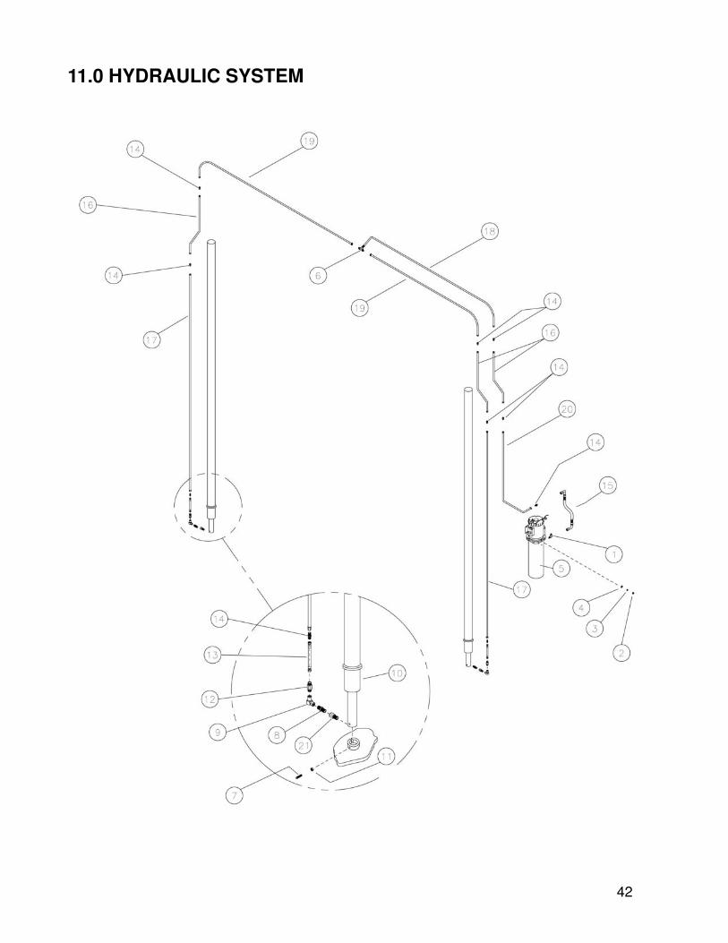
11.0 HYDRAULIC SYSTEM

43
11.1 Hydraulic System Parts List
Item Part # Description Qty1 6-0804 ELBOW 90 DEG 9/16 SAE M-3/8 JIC M 1
2 6-0294 HEX NUT 5/16”-18 UNC 4
3 6-0674 LOCKWASHER 5/16” I.D 4
4 6-0295 WASHER FLAT 5/16” ID SAE 4
5 6-3150 POWER UNIT 1
6 6-1372 3/8” UNION TEE M JIC 2
7 6-3061 SET SCREW 3/8”-16 1”LG 2
8 6-3876 ADAPTOR 3/8” M NPT – 3/8” M NPT 2
9 6-0006 COUPLING 3/8” F NPT 90 DEG FORGED 2
10 2-2518 HYDRAULIC CYLINDER 2
11 6-3119 HEX NUT 3/8”-16 UNC 11
12 6-1684 VELOCITY FUSE 8GPM 2
13 2-2136 HYDRAULIC HOSE ASSEMBLY 2
14 6-0286 ADAPTOR 3/8” M JIC – 3/8” M JIC 2
15 6-3148 HYDRAULIC HOSE ASSEMBLY 1
16 6-3151 HYDRAULIC TUBING ASSEMBLY 3
17 6-3153 HYDRAULIC TUBING ASSEMBLY 2
18 6-3114 HYDRAULIC TUBING ASSEMBLY 1
19 6-3152 HYDRAULIC TUBING ASSEMBLY 2
20 6-3149 HYDRAULIC TUBING ASSEMBLY 1
21 6-3205 1/4" NPT M - 3/8" NPT F ADAPTOR 2

44
12.0 SAFETY SYSTEM

45
12.1 Safety System Parts List
Item Part # Description Qty1 1-3026 MICRO CABLE CARRIER ASSEMBLY 2
2a 80307 PNEUMATIC TUBING 4mm 127” LG 1
b " PNEUMATIC TUBING 4mm 94 3/4” LG 1
c " PNEUMATIC TUBING 4mm 222” LG 1
d " PNEUMATIC TUBING 4mm 225” LG 1
3 6-3136 AIR VALVE 1
4 8-0141 PNEUMATIC TUBING 1/4” DIA 100” LG 1
5 6-3131 PLUG IN ELBOW 5/32” – 5/32” 2
6 6-3135 MALE ELBOW 1/4” – 1/4” NPT 1
7 6-3133 HOSE TO HOSE COUPLING 5/32” – 5/32” 3
8 6-0203 HEX BOLT 3/8” –16 UNC 1 1/2” LG. PLT 12
9 6-0060 WASHER FLAT 1/4” I.D SAE 4
10 6-3111 AIR CYLINDER 3/4 BX(1.00) STROKE 2
11 6-0663 LOCKWASHER INTERNAL TOOTH 5/8 2
12 6-3110 AIR CYLINDER MTG. BRKT 2 POST AIR RELEASE 2
13 2-2249 SAFETY RELEASE BRKT 2 POST AIR RELEASE 2
14 6-1643 HEX BOLT 7/8”-9 x 3 1/2” LG 2
15 1-2996 SAFETY BLOCK SPACER 2
16 1-3022 SAFETY DOG ASSY & WELDMENT 2
17 6-0725 WASHER FLAT 7/8” I.D 2
18 6-3124 LOCKNUT 7/8”-9 UNC NYLON 2
19 6-0625 WASHER 3/8” 2
20 6-3145 COTTER PIN 3/32” x 1” 2
21 6-3144 HEX JAM NUT 1/4”-28 UNF 4
22 6-1563 LOCKNUT 1/4”-28 NYLON UNF 2
23 6-3129 MALE ELBOW 5/32” –1/8” NPT 2
24 6-3130 MALE CONNECTOR 1/4” - 1/8” NPT 1
25 6-3132 MALE RUN’G TEE 5/32” – 5/32” – 1/8” 1
46
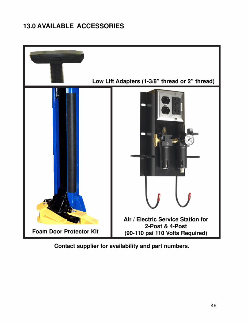
13.0 AVAILABLE ACCESSORIES
Low Lift Adapters (1-3/8” thread or 2” thread)
Foam Door Protector Kit
Air / Electric Service Station for2-Post & 4-Post
(90-110 psi 110 Volts Required)
Contact supplier for availability and part numbers.


![Setia Insight Nov07-Part1[1]](https://static.fdocuments.net/doc/165x107/577d26f61a28ab4e1ea2ab8e/setia-insight-nov07-part11.jpg)


