Seamless Hardware Module Swapping for Partially Reconfigurable Stream Processing Systems
date post
20-Dec-2015Category
view
216download
0
1/58
Chapter 8Hardware-Software Co-design of Reconfigurable Systems
2/58
Outline
Introduction Reconfigurable Systems Partitioning and Scheduling Operating System for
Reconfigurable Systems Design Example Conclusions
3/58
Outline
Introduction Reconfigurable Systems Partitioning and Scheduling Operating System for
Reconfigurable Systems Design Example Conclusions
4/58
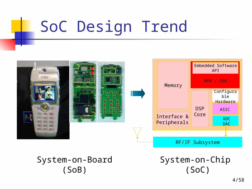
SoC Design Trend
Memory
Embedded SoftwareAPI
MPU / CPU
Interface & Peripherals
DSPCore
ASIC
ADCDAC
RF/IF Subsystem
Configurable Hardware
System-on-Board (SoB)
System-on-Chip (SoC)
5/58
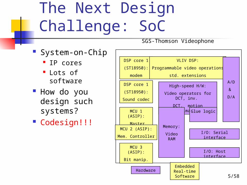
The Next Design Challenge: SoC
System-on-Chip IP cores Lots of software
How do you design such systems?
Codesign!!!
DSP core 1
(ST18950):
Sound codec
DSP core 1
(ST18950):
modem
MCU 1 (ASIP):
Master control
MCU 2 (ASIP):
Mem. Controller
MCU 3 (ASIP):
Bit manip.
VLIV DSP:
Programmable video operations
std. extensions
High-speed H/W:
Video operators for DCT, inv.
DCT, motion estimation
Memory:
Video RAM
Glue logic
I/O: Serial interface
I/O: Host interface
A/D
&
D/A
HardwareEmbedded Real-time Software
SGS-Thomson Videophone

6/58
System Design
Performance
Flexibility
Microprocessor
ASIC
ASIP andConfigurable p
?ReconfigurableSoC
7/58
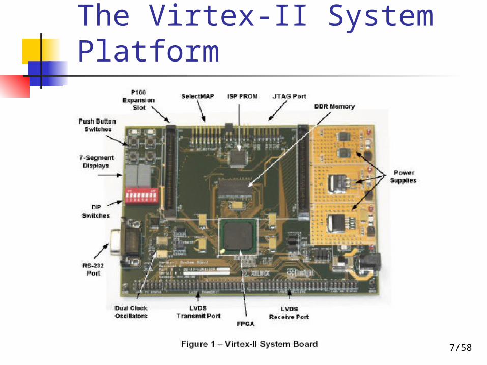
The Virtex-II System Platform

8/58
Reconfigurable Systems
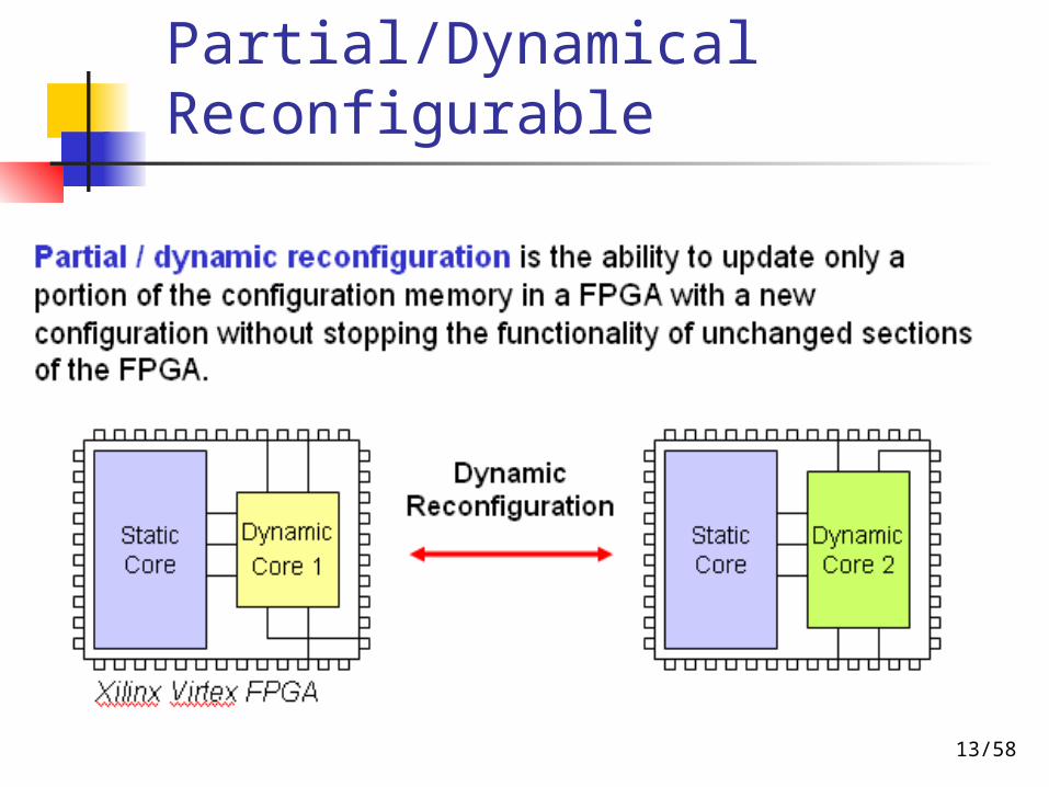
RAM or FLASH memory-based FPGA/CPLD can be dynamically reconfigured.
Its configuration can be changed while the rest of the circuit is fully operational.
Two techniques used to reduce the configuration time are:
Partial configuration Multiple-context configuration memory

9/58
Outline
Introduction Reconfigurable Systems Partitioning and Scheduling Operating System for
Reconfigurable Systems Design Example Conclusions
10/58
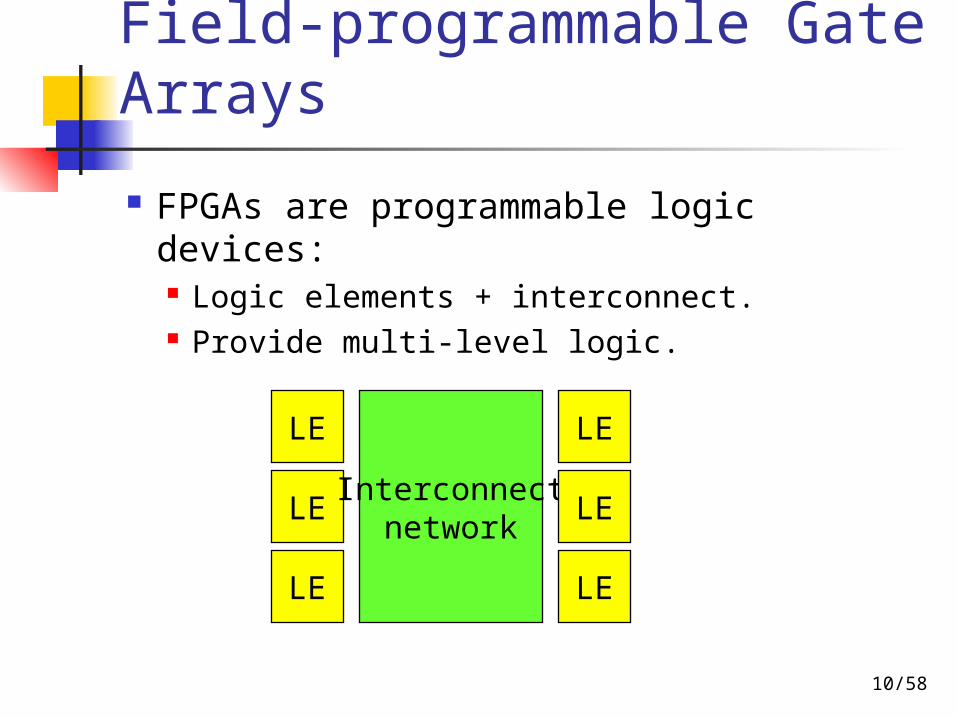
Field-programmable Gate Arrays
FPGAs are programmable logic devices: Logic elements + interconnect. Provide multi-level logic.
LE
LE
LE
Interconnectnetwork
LE
LE
LE
11/58
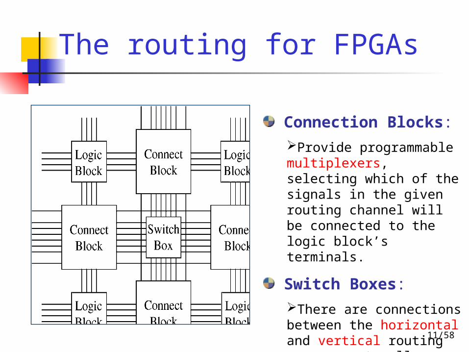
Connection Blocks:
Provide programmable multiplexers, selecting which of the signals in the given routing channel will be connected to the logic block’s terminals.
Switch Boxes:
There are connections between the horizontal and vertical routing resources to allow signals to change their routing direction.
The routing for FPGAs

12/58
Popular Reconfigurable Logics
Two main architectures of reconfigurable logic (FPGA) Altera
Logic Array Blocks of Logic Elements (LE) ARM 922T core in embedded stripe Nios
Xilinx Slice of Configurable Logic Blocks (CLB) 4 PowerPC 405 hard cores MicroBlaze
13/58
Partial/Dynamical Reconfigurable
14/58
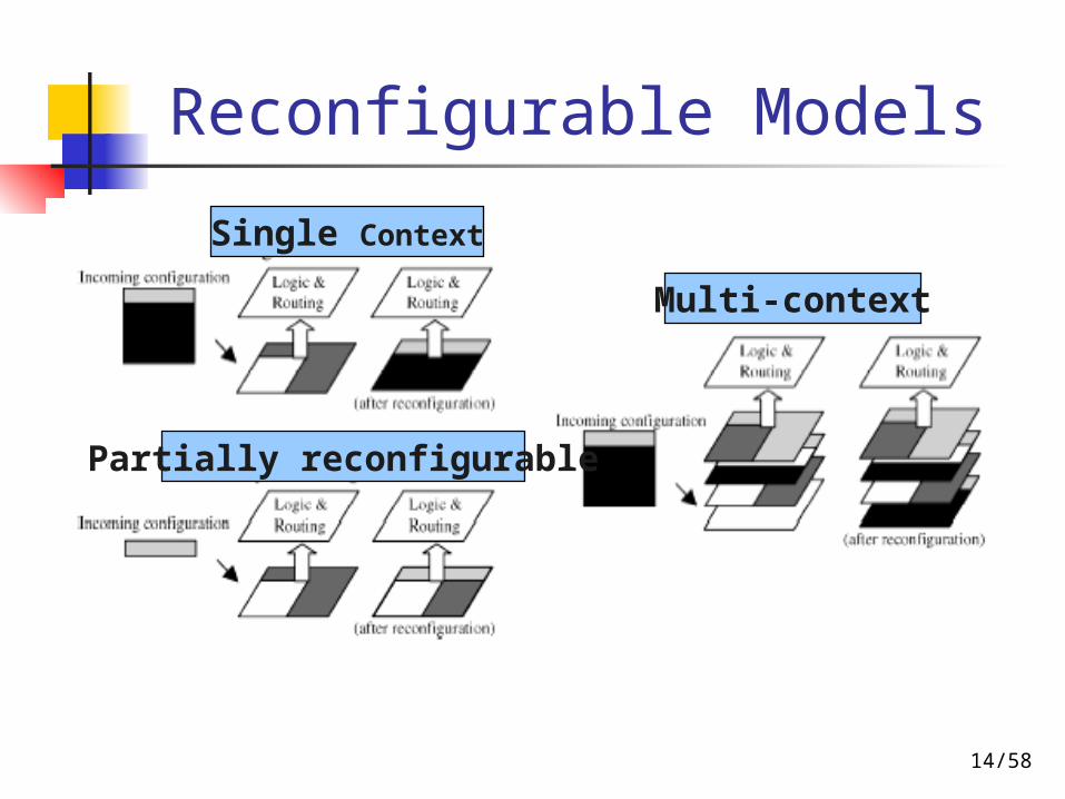
Reconfigurable Models
Single Context
Multi-context
Partially reconfigurable
15/58
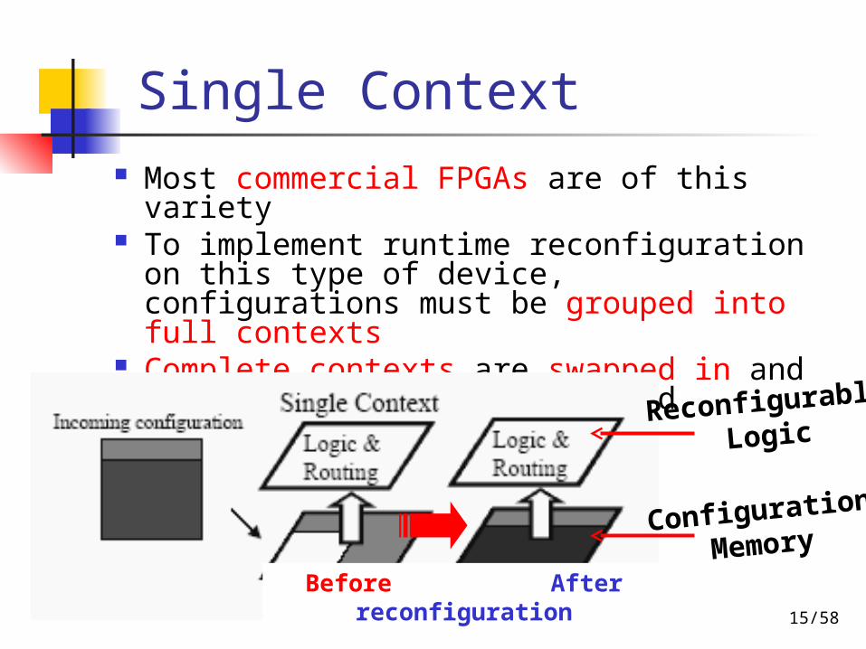
Single Context Most commercial FPGAs are of this
variety To implement runtime reconfiguration
on this type of device, configurations must be grouped into full contexts
Complete contexts are swapped in and out of the hardware as needed
Reconfigurable
Logic
Configuration
Memory
Before After reconfiguration

16/58
Multi-context
Multiple layers of programming bits, where each layer can be active at a different point in time
Allows for an extremely fast context switch (on the order of nanoseconds)
Allow for background loading, permitting one context to be configuring while another is in execution

17/58
Partially Reconfigurable
Selectively programmed without a complete reconfiguration
Small areas of the array can be modified without requiring that the entire logic array be reprogrammed
Require much less time than a full-chip reconfiguration due to the reduced data traffic

18/58
Reconfigurable System Example
Dynamically Reconfigurable Logic
Audio Codec
Image Codec Graphics
USB Bluetooth
Wireless
PPC 405
On-Chip Dynamically Reconfigurable Bus
Reconf
Codec
Block
Reconf
I/O
Block
Reconfigurable blocks
Fixed blocks
Fixed blocks
Task Interface Task InterfaceTask Interface Task Interface
PPC 405
Reconfigurable blocks
…
…Task Interface
Video Codec
Arbiter +
Comm-unication
Block+
ICAP Module
GPRS/GSM
Control/Data Input
Control/Data
Output
Reconfiguration Reconfiguration
Arbiter +
Comm-unication
Block+
ICAP Module
Reconfiguration Memory
Fixed I/OFixed I/O

19/58
Outline
Introduction Reconfigurable Systems Partitioning and Scheduling Operating System for
Reconfigurable Systems Design Example Conclusions

20/58
Relations Among Partitioning Issues
Output
High Level Abstraction
Decomposition of functional objects • Metrics and estimations• Partitioning algorithms• Objective and closeness functions
Component allocation
21/58
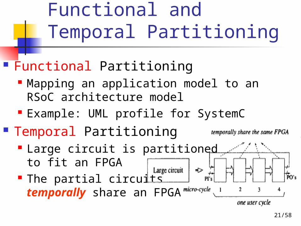
Functional and Temporal Partitioning
Functional Partitioning Mapping an application model to an RSoC
architecture model Example: UML profile for SystemC
Temporal Partitioning Large circuit is partitioned
to fit an FPGA The partial circuits temporally share an FPGA

22/58
Functional Partitioning
Network Flow Graph Optimal solution, slow, not practical
Network Clubbing Heuristic solution, practical, profiling
Simulated Annealing Heuristic sub-optimal solution, fast,
practical Genetic Algorithm
Heuristic good solution, slow, practical
23/58
Temporal Partitioning
List Scheduling Force-Directed Scheduling Network Flow Graph Integer Linear Programming Hierarchical Flow

24/58
Partitioning Example
25/58
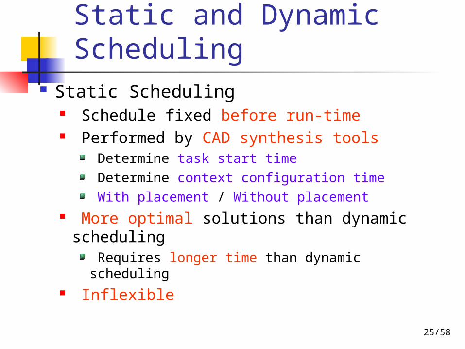
Static and Dynamic Scheduling
Static Scheduling Schedule fixed before run-time Performed by CAD synthesis tools
Determine task start time Determine context configuration time With placement / Without placement
More optimal solutions than dynamic scheduling
Requires longer time than dynamic scheduling Inflexible
26/58
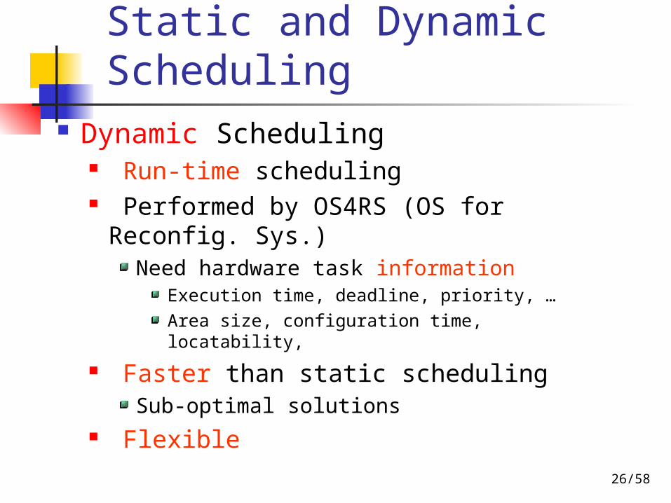
Static and Dynamic Scheduling
Dynamic Scheduling Run-time scheduling Performed by OS4RS (OS for Reconfig.
Sys.)Need hardware task information
Execution time, deadline, priority, …Area size, configuration time, locatability,
Faster than static schedulingSub-optimal solutions
Flexible
27/58
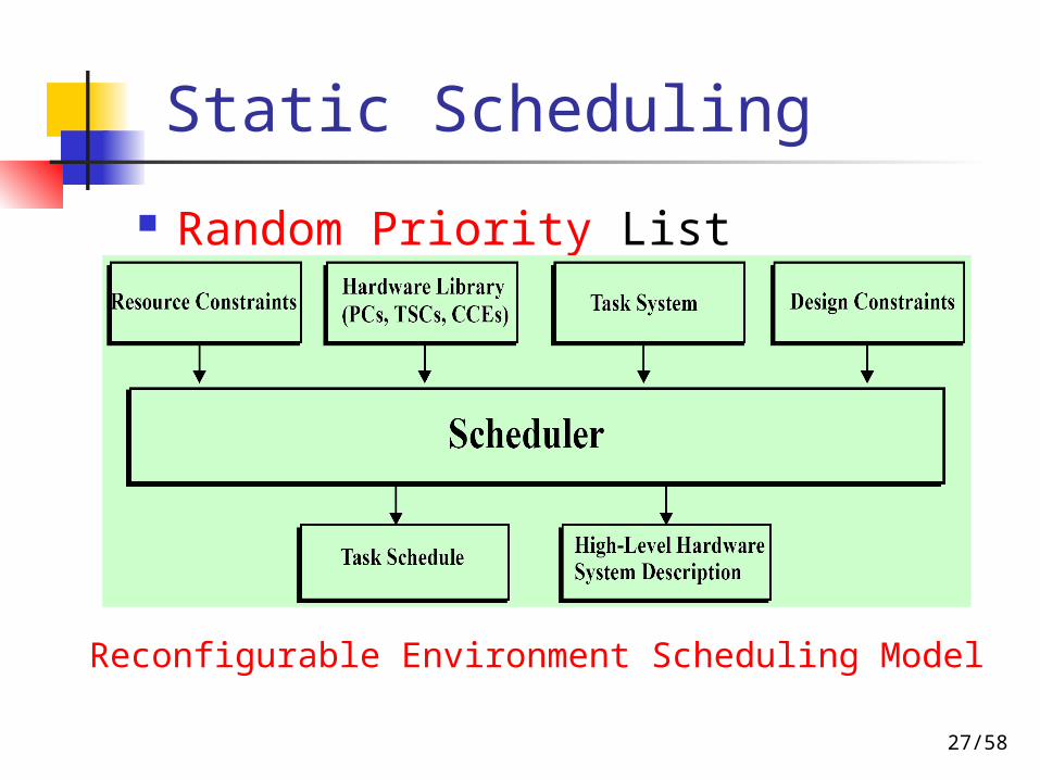
Static Scheduling
Random Priority List Scheduling
Reconfigurable Environment Scheduling Model

28/58
Dynamic Scheduling
Dynamic scheduling methods Priority based Non-preemptive Preemptive Horizon and Stuffing
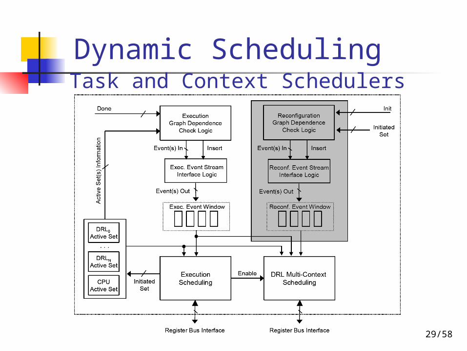
29/58
Dynamic SchedulingTask and Context Schedulers

30/58
Dynamic Scheduling Architecture Model Online Scheduler
31/58
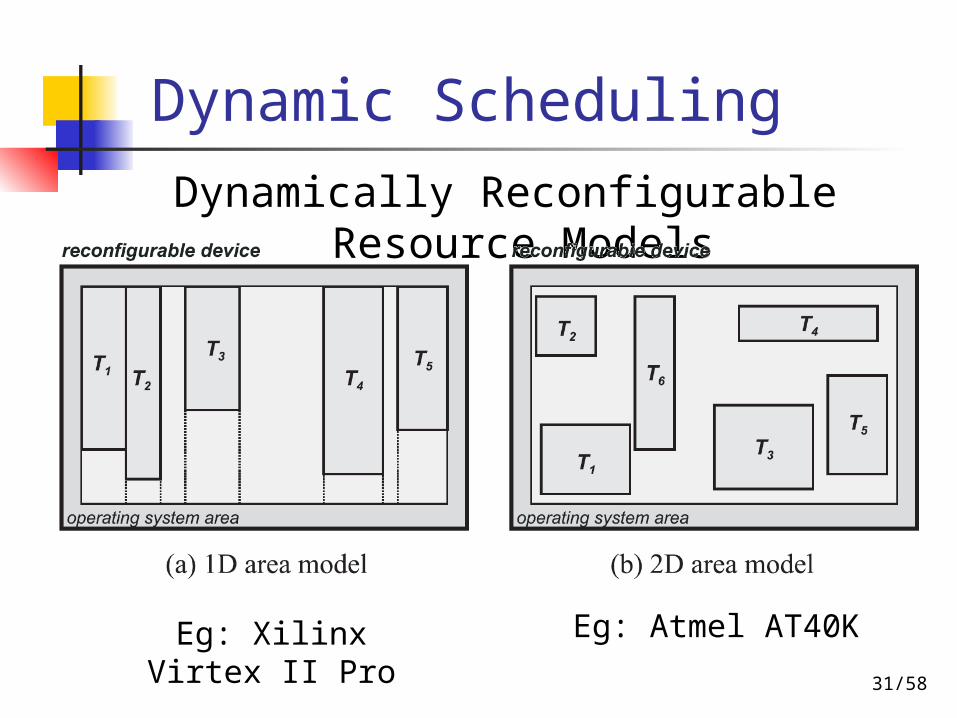
Dynamic Scheduling
Dynamically Reconfigurable Resource Models
Eg: Xilinx Virtex II Pro Eg: Atmel AT40K

32/58
Outline
Introduction Reconfigurable Systems Partitioning and Scheduling Operating System for
Reconfigurable Systems Design Example Conclusions

33/58
OS4RS
Mobile, wireless multimedia applications demand more dynamic performance and pervasiveness
State-of-art FPGA chips allow hardware tasks to be changed at run-time
An OS is thus needed for managing all those hardware tasks efficiently and correctly Allocation, partitioning, scheduling,
placement, routing, relocating, etc.
34/58
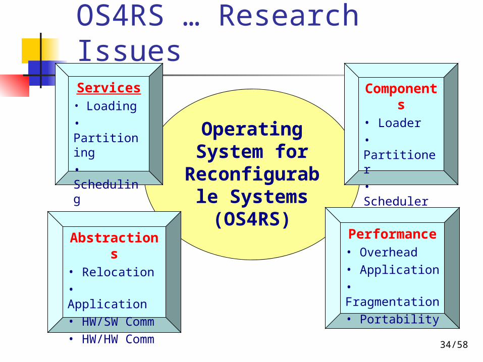
OS4RS … Research Issues
Operating System for
Reconfigurable Systems (OS4RS)
Services• Loading
• Partitioning
• Scheduling
• Routing
Components• Loader
• Partitioner
• Scheduler
• Router
Abstractions• Relocation
• Application
• HW/SW Comm
• HW/HW Comm
Performance• Overhead
• Application
• Fragmentation
• Portability
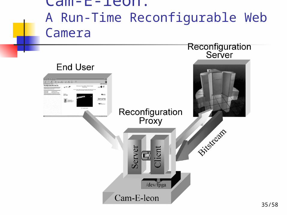
35/58
Cam-E-leon: A Run-Time Reconfigurable Web Camera
36/58
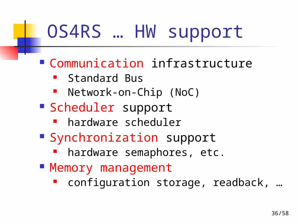
OS4RS … HW support
Communication infrastructure Standard Bus Network-on-Chip (NoC)
Scheduler support hardware scheduler
Synchronization support hardware semaphores, etc.
Memory management configuration storage, readback, …
37/58
Outline
Introduction Reconfigurable Systems Partitioning and Scheduling Operating System for
Reconfigurable Systems Design Example Conclusions
38/58
Module-Based Partial Reconfiguration (PR)
Design Example:Counter Design Tutorial
Based on Gregory Mermoud’s “A Module-Based Dynamic Partial Reconguration Tutorial” at http://ic2.epfl.ch/~gmermoud/files/publications/DPRtutorial.pdf
39/58
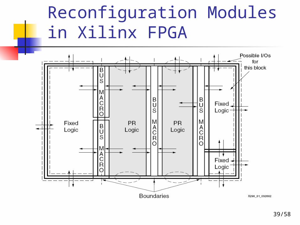
Reconfiguration Modules in Xilinx FPGA
40/58
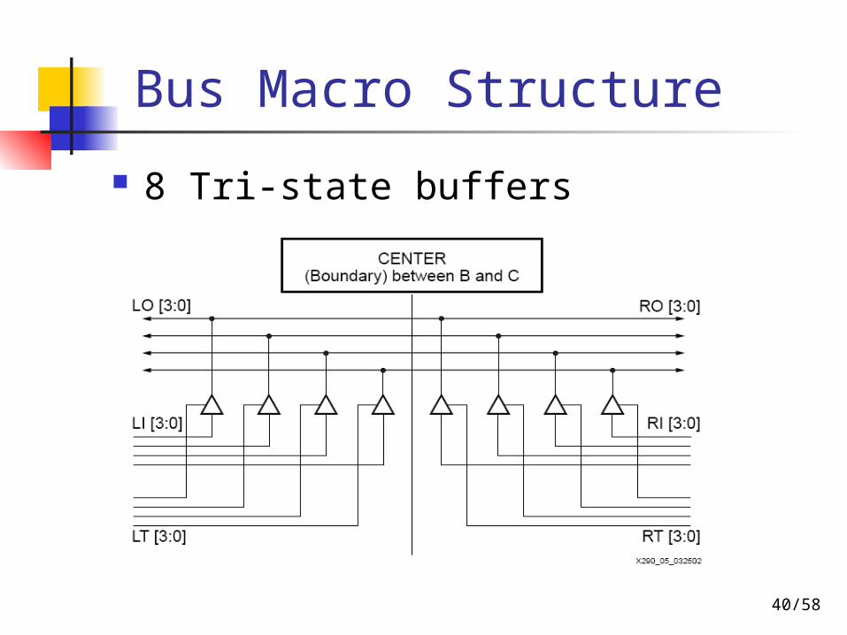
Bus Macro Structure
8 Tri-state buffers

41/58
Counter Design Architecture
A basic schematic of the design

42/58
Partial Reconfigurable Design Flow
43/58
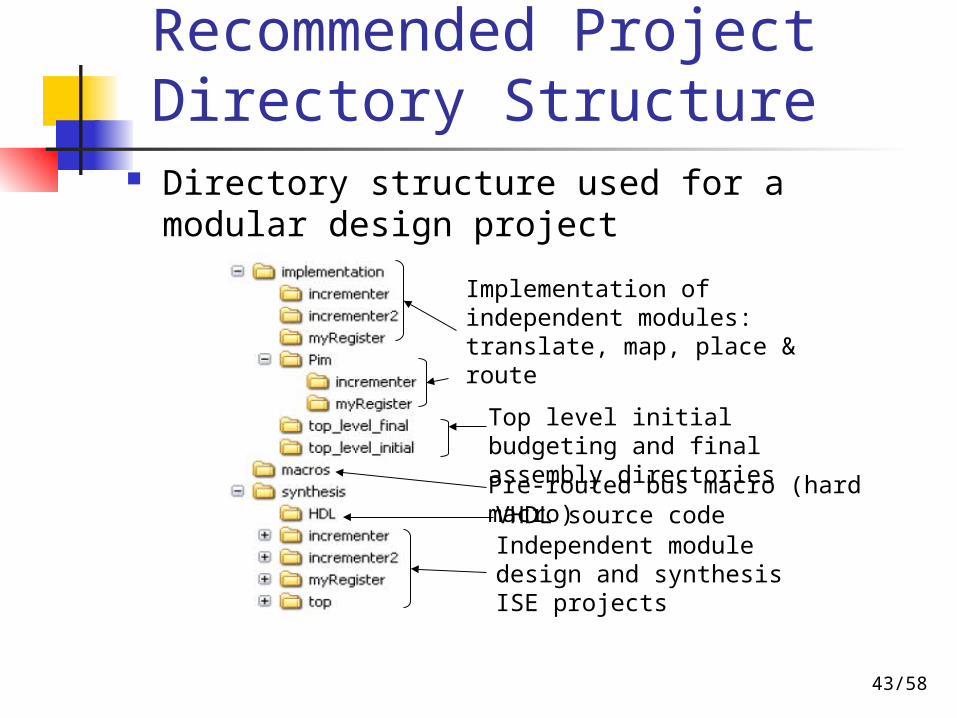
Recommended Project Directory Structure
Directory structure used for a modular design project
Top level initial budgeting and final assembly directories
Independent module design and synthesis ISE projects
Implementation of independent modules: translate, map, place & route
Pre-routed bus macro (hard macro)VHDL source code
44/58
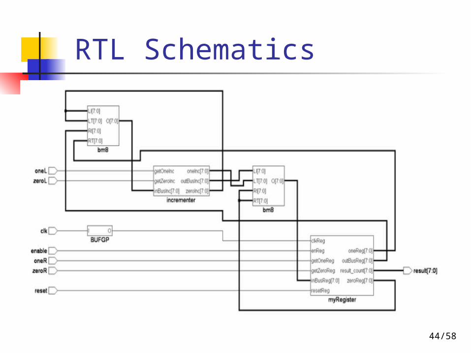
RTL Schematics

45/58
Module-Based PR Design Flow
Design entry (Top-level design) HDL entry / synthesis (use ISE) Synthesis options (in ISE)
Add I/O buffer (for top-level): Yes Keep Hierarchy: Soft
Design entry (Independent module design)
HDL entry / synthesis (use ISE) One ISE project for each module Synthesis options (in ISE)
Add I/O buffer (for modules): No Keep Hierarchy: Yes
ISE projects are created in synthesis/ directory
46/58
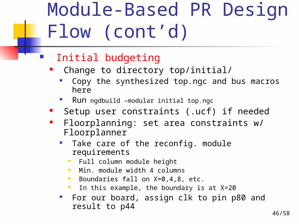
Module-Based PR Design Flow (cont’d)
Initial budgeting Change to directory top/initial/
Copy the synthesized top.ngc and bus macros here
Run ngdbuild –modular initial top.ngc Setup user constraints (.ucf) if needed Floorplanning: set area constraints w/
Floorplanner Take care of the reconfig. module requirements
Full column module height Min. module width 4 columns Boundaries fall on X=0,4,8, etc. In this example, the boundary is at X=20
For our board, assign clk to pin p80 and result to p44

47/58
Module-Based PR Design Flow (cont’d) Manually modify .ucf (top.ucf)
Add in the ucfAREA_GROUP "AG_increm" MODE = RECONFIG;AREA_GROUP "AG_myReg" MODE = RECONFIG;INST "busRegToInc/bus1" LOC = "TBUF_R18C16.0" ;INST "busRegToInc/bus2" LOC = "TBUF_R20C16.0" ;INST "busIncToReg/bus1" LOC = "TBUF_R22C16.0" ;INST "busIncToReg/bus2" LOC = "TBUF_R24C16.0" ;
Bus macro has to start at 4 columns left of boundarye.g., X=16 when boundary at X=20
Bus macro must start at even row (Y=even) Run ngdbuild –modular initial top.ngc to produce
a new ngd to be loaded into Floorplanner for verification
48/58
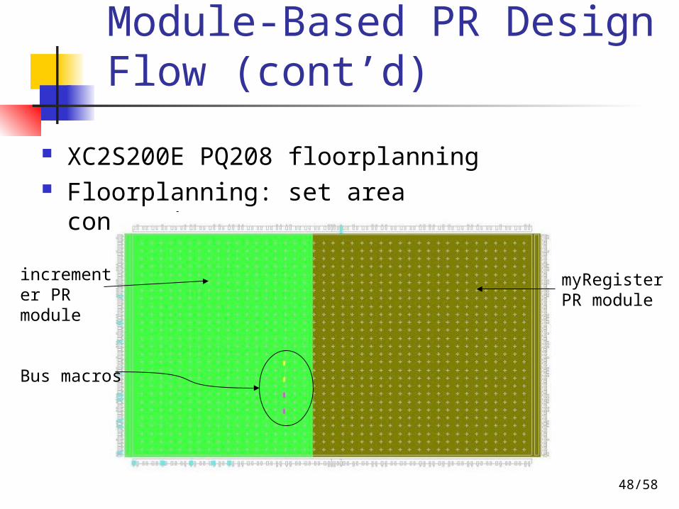
Module-Based PR Design Flow (cont’d)
XC2S200E PQ208 floorplanning Floorplanning: set area constraints 、 IOBs …
Bus macros
incrementer PR module
myRegister PR module

49/58
Module-Based PR Design Flow (cont’d)
Active module implementation Change to the module dir at
modules/[module]/ Copy the synthesized .ngc for each module
from synthesis/[module]/ If module-specific constraints are needed, copy
the previously produced top.ucf into the directory and add constraints
Implement and publish each module ngdbuild –modular module –active incrementer ..\..\
initial\top.ngc map top.ngd par –w top.ncd top1.ncd pimcreate –ncd top1.ncd ..\..\pims
50/58
Module-Based PR Design Flow (cont’d)
Final assembly Change dir to top/final/
Copy bus macros here Assemble the modules
ngdbuild –modular assemble –pimpath ..\..\pims ..\initial\top.ngc
map top.ngd par –w top.ncd top_routed.ncd
51/58
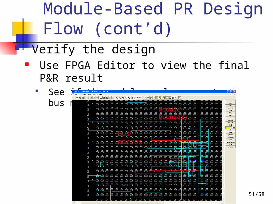
Module-Based PR Design Flow (cont’d)
Verify the design Use FPGA Editor to view the final P&R
result See if the modules only connect at bus
macrosModule boundary
Bus macros
52/58
Module-Based PR Design Flow (cont’d)
Creating bitstreams Initial bitstream of the complete design
Change to dir top/final/ bitgen –w top_routed.ncd
top_routed.bit Partial bitstream for each module
Change to the dir of each module (modules/[module]/
bitgen –g ActiveReconfig:Yes –d top1.ncd top_partial.bit
53/58
Module-Based PR Design Flow (cont’d)
Configure the real board Download bitstreams with iMPACT to
XC2S200e When the board is running, download
a partial bitstream to partially reconfig. the chip

54/58
Implementation Results
FPGA Routing
55/58
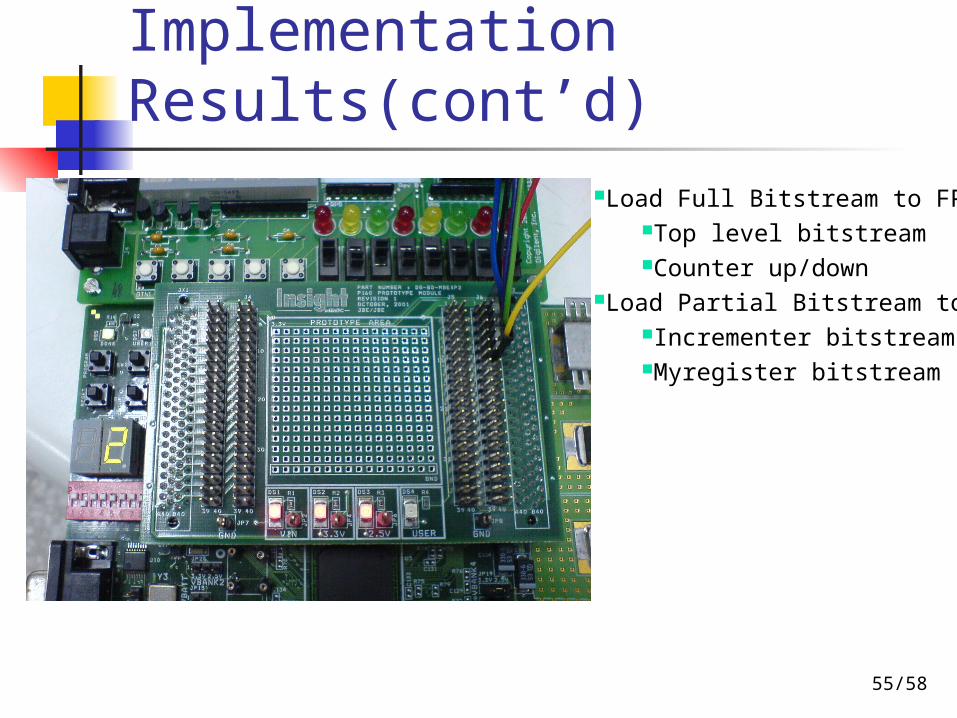
Implementation Results(cont’d)
Load Full Bitstream to FPGATop level bitstreamCounter up/down
Load Partial Bitstream to FPGAIncrementer bitstreamMyregister bitstream
56/58
Outline
Introduction Reconfigurable Systems Partitioning and Scheduling Operating System for
Reconfigurable Systems Design Example Conclusions

57/58
Conclusions
Reconfigurable systems will be a promising system design architecture for future powerful applications
There are lots of research issues still left open in this field
There are lots of practical issues still left unsolved in this field
58/58
Q & A