1564A Barcode Scanner
318
1564A Barcode Scanner Setup barcodes included. Version 2.11
Transcript of 1564A Barcode Scanner
1564A Barcode Scanner
Setup barcodes included.
Version 2.11

Copyright © 2011~2019 CIPHERLAB CO., LTD. All rights reserved
The software contains proprietary information of CIPHERLAB CO., LTD.; it is provided under a license agreement containing restrictions on use and disclosure and is also protected by copyright law. Reverse engineering of the software is prohibited.
Due to continued product development this information may change without notice. The information and intellectual property contained herein is confidential between CIPHERLAB and the client and remains the exclusive property of CIPHERLAB CO., LTD. If you find any problems in the documentation, please report them to us in writing. CIPHERLAB does not warrant that this document is error-free.
No part of this publication may be reproduced, stored in a retrieval system, or transmitted in any form or by any means, electronic, mechanical, photocopying, recording or otherwise without the prior written permission of CIPHERLAB CO., LTD.
For product consultancy and technical support, please contact your local sales representative. Also, you may visit our web site for more information.
The CipherLab logo is a registered trademark of CIPHERLAB CO., LTD.
All brand, product and service, and trademark names are the property of their registered owners.
The editorial use of these names is for identification as well as to the benefit of the owners, with no intention of infringement.
CIPHERLAB CO., LTD. Website: http://www.cipherlab.com
FOR USA
This equipment has been tested and found to comply with the limits for a Class B digital device, pursuant to Part 15 of the FCC Rules. These limits are designed to provide reasonable protection against harmful interference in a residential installation. This equipment generates, uses and can radiate radio frequency energy and, if not installed and used in accordance with the instructions, may cause harmful interference to radio communications. However, there is no guarantee that interference will not occur in a particular installation. If this equipment does cause harmful interference to radio or television reception, which can be determined by turning the equipment off and on, the user is encouraged to try to correct the interference by one or more of the following measures:
Reorient or relocate the receiving antenna. Increase the separation between the equipment and receiver. Connect the equipment into an outlet on a circuit different from that to which the
receiver is connected. Consult the dealer or an experienced radio/TV technician for help.
This device complies with Part 15 of the FCC Rules. Operation is subject to the following two conditions: (1) This device may not cause harmful interference, and (2) this device must accept any interference received, including interference that may cause undesired operation.
FOR CANADA
This digital apparatus does not exceed the Class B limits for radio noise emissions from digital apparatus as set out in the interference-causing equipment standard entitled "Digital Apparatus," ICES-003 of Industry Canada. This device complies with Part 15 of the FCC Rules. Operation is subject to the following two conditions: (1) This device may not cause harmful interference, and (2) this device must accept any interference received, including interference that may cause undesired operation.
Cet appareil numerique respecte les limites de bruits radioelectriques applicables aux appareils numeriques de Classe B prescrites dans la norme sur le material brouilleur: "Appareils Numeriques," NMB-003 edictee par l'Industrie.
IMPORTANT NOTICES

FOR HAND-HELD PRODUCT WITH RF FUNCTIONS
The 1564A unit (FCC ID: Q3N-1564A) complies with FCC radiation exposure limits set forth for uncontrolled environment and meets the FCC radio frequency (RF) Exposure Guidelines in Supplement C to OET65. The unit has very low level of RF energy that it is deemed to comply without testing of specific absorption ratio (SAR).
The 3656 unit (FCC ID: Q3N-3656CRADLE) complies with FCC radiation exposure limits set forth for an uncontrolled environment. This equipment should be installed and operated with minimum distance 20 cm between the radiator & your body. It only operated in hand-held used. If you only transfer data to the host wirelessly, please keep the minimum distance 20 cm between machine & your body.
FOR PRODUCT WITH LASER
CAUTION
This laser component emits FDA / IEC Class 2 laser light at the exit port. Do not stare into beam.
SAFETY PRECAUTIONS
RISK OF EXPLOSION IF BATTERY IS REPLACED BY AN INCORRECT TYPE. DISPOSE OF USED BATTERIES ACCORDING TO THE INSTRUCTIONS.
The use of any batteries or charging devices, which are not originally sold or manufactured by CipherLab, will void your warranty and may cause damage to human body or the product itself.
DO NOT disassemble, incinerate or short circuit the battery. DO NOT expose the scanner or the battery to any flammable sources. For green-environment issue, it's important that batteries should be recycled in a
proper way. Under no circumstances, internal components are self-serviceable. The charging device uses an AC power adaptor. A socket outlet shall be installed near
the equipment and shall be easily accessible. Make sure there is stable power supply for the scanner or its peripherals to operate properly.
CARE & MAINTENANCE
Use a clean cloth to wipe dust off the scanning window and the body of the scanner as well as the charging device. DO NOT use/mix any bleach or cleaner.
If you want to put away the scanner for a period of time, download the collected data to a host computer when in the memory mode, and then take out the battery. Store the scanner and battery separately.
When the scanner resumes its work, make sure the battery is fully charged before use.
If you shall find the scanner malfunctioning, write down the specific scenario and consult your local sales representative.
Version Date Notes
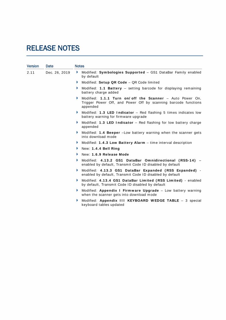
2.11 Dec. 26, 2019 Modified: Symbologies Supported – GS1 DataBar Family enabled by default
Modified: Setup QR Code – QR Code limited
Modified: 1.1 Battery – setting barcode for displaying remaining battery charge added
Modified: 1.1.1 Turn on/off the Scanner – Auto Power On, Trigger Power Off, and Power Off by scanning barcode functions appended
Modified: 1.3 LED Indicator – Red flashing 5 times indicates low battery warning for firmware upgrade
Modified: 1.3 LED Indicator – Red flashing for low battery charge appended
Modified: 1.4 Beeper –Low battery warning when the scanner gets into download mode
Modified: 1.4.3 Low Battery Alarm – time interval description
New: 1.4.4 Bell Ring
New: 1.6.9 Release Mode
Modified: 4.13.2 GS1 DataBar Omnidirectional (RSS-14) – enabled by default, Transmit Code ID disabled by default
Modified: 4.13.3 GS1 DataBar Expanded (RSS Expanded) - enabled by default, Transmit Code ID disabled by default
Modified: 4.13.4 GS1 DataBar Limited (RSS Limited) - enabled by default, Transmit Code ID disabled by default
Modified: Appendix I Firmware Upgrade – Low battery warning when the scanner gets into download mode
Modified: Appendix III KEYBOARD WEDGE TABLE – 3 special keyboard tables updated
RELEASE NOTES
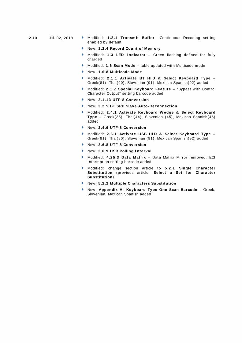
2.10 Jul. 02, 2019 Modified: 1.2.1 Transmit Buffer –Continuous Decoding setting enabled by default
New: 1.2.4 Record Count of Memory
Modified: 1.3 LED Indicator – Green flashing defined for fully charged
Modified: 1.6 Scan Mode – table updated with Multicode mode
New: 1.6.8 Multicode Mode
Modified: 2.1.1 Activate BT HID & Select Keyboard Type – Greek(81), Thai(90), Slovenian (91), Mexican Spanish(92) added
Modified: 2.1.7 Special Keyboard Feature – “Bypass with Control Character Output” setting barcode added
New: 2.1.13 UTF-8 Conversion
New: 2.2.5 BT SPP Slave Auto-Reconnection
Modified: 2.4.1 Activate Keyboard Wedge & Select Keyboard Type – Greek(35), Thai(44), Slovenian (45), Mexican Spanish(46) added
New: 2.4.6 UTF-8 Conversion
Modified: 2.6.1 Activate USB HID & Select Keyboard Type – Greek(81), Thai(90), Slovenian (91), Mexican Spanish(92) added
New: 2.6.8 UTF-8 Conversion
New: 2.6.9 USB Polling Interval
Modified: 4.25.3 Data Matrix – Data Matrix Mirror removed; ECI Information setting barcode added
Modified: change section article to 5.2.1 Single Character Substitution (previous article: Select a Set for Character Substitution)
New: 5.2.2 Multiple Characters Substitution
New: Appendix VI Keyboard Type One-Scan Barcode – Greek, Slovenian, Mexican Spanish added
2.09 Jun. 29, 2018 Replace “1564” with “1564A” including the FCC ID
Modified: Symbologies Supported – Addon 2/Addon 5 for UPC-A appended
Modified: 1.2.1 Transmit Buffer – Continuous Decoding setting barcodes added
Modified: 1.8 Delay between Re-read – Laser mode added
Modified: 2.1 BT HID - 83 PCAT (Russian), 88 PCAT (Cyrillic on Russian), 89 PCAT (Armenian) appended
Modified: 2.4 Keyboard Wedge via 3656 - 37 PCAT (Russian), 42 PCAT (Cyrillic on Russian), 43 PCAT (Armenian) appended
Modified: 2.6 USB HID via 3656 - 83 PCAT (Russian), 88 PCAT (Cyrillic on Russian), 89 PCAT (Armenian) appended
Modified: 2.1.6. HID Character Transmit Mode – “By Character” by default
Modified: 2.1.7/2.4.5/2.6.6 Special Keyboard Feature – “Bypass” by default
Modified: 2.1.8 Keypad Support for iPhone/iPad – “Use Trigger Key to Show or Hide Keypad” by default
Modified: 2.1.9 Transmit Speed – “Fast” by default
Modified: 2.1.10 Simple Pairing for iPhone/iPad & 3.2.2 Configure Related Settings – BT Security Simple Pairing enabled by default
New: Appendix VI Keyboard Type One-Scan Barcode
2.00 Dec. 16, 2016 Modified: 1.10 – Addon security (2~16 times; default:10)
New: 1.17 2D Decode Setting
Modified: 2.1.6 – note for turning off iOS Auto-Correction added
Modified: 2.3.1 – a single 1D barcode (SeTcOn) for connecting to a target device added
New: 2.6.7 USB HID via 3656 Auto-Reconnection
New: 2.7.4 USB VCOM via 3656 Auto-Reconnection
Modified: 3.1.1 – a single 1D barcode (SeTcOn) for connecting to a target device added
Modified: 4.25.3 Data Matrix – Field Separator, Application ID Mark setting barcodes added
Modified: 4.25.5 QR Code – GS1 formatting, Field Separator, Application ID Mark setting barcodes added
1.10 Dec. 16, 2015 New: 1.11.1 Behavior of 1564
New: 1.11.2 Behavior of 1564A (Auto Power On for 1564A included)
Modified: 2.1.8 – setting barcodes for showing/hiding iPhone/iPad onscreen keypad added (1564A)
1.09 Aug. 20, 2015 Modified: descriptions relating to CD-ROM removed
New: 2.2.4 BT SPP Slave Hardware Flow Control
New: 2.3.5 BT SPP Master Hardware Flow Control
New: 2.3.6 BT SPP Master Auto-Reconnection
New: 4.16.1 EAN-13 Addon Modes
1.08 Jun. 18, 2014 New: 1.15 – Illumination Brightness setup barcode added
New: 1.16 – Serial Number Stamp setup barcode added
New: 1.16.1 – separator between S/N and data
New: 2.1.11 – BT HID Slave/Master Switching
New: 2.1.12 – BT HID Auto-Reconnection
New: 3.2.2 – changing device name barcode added
New: 4.11.3 – GS1 Formatting, Application ID Mark
Modified: 4.13.2 – add GS1 formatting (Omnidirectional) barcodes
Modified: 4.13.3 – add GS1 formatting (Expanded) barcodes
Modified: 4.13.4 – add GS1 formatting (Limited) barcodes
New: 4.13.6 – Field Separator
New: 4.13.7 – Application ID Mark
New: 4.15.1 – Transmit Check Digit for EAN-8
New: 4.16.3 – Transmit Check Digit for EAN-13
Modified: 4.21.1 – add GS1 formatting (Composite CC-A/B) barcodes
Modified: 4.21.2 – add GS1 formatting (Composite CC-C) barcodes
New: 4.21.6 – Field Separator
New: 4.21.7 – Application ID Mark
Modified: Appendix II – #@BEEP,xx, #@RLED,xx, #@GLED,xx commands added
1.07 Mar. 04, 2013 New: Quick Start – Create 2D One-Scan Barcode
New: 1.14 Mobile Phone/Display Mode
New: 2.1.9 BT HID – Transmit Speed setup barcodes
New: 2.1.10 Simple Pairing for iPhone/iPad
New: 2.3.1 Activate Bluetooth SPP Master Mode – 2D barcode for connecting to a target device added
New: 3.1.1 Connect to 3656 – 2D barcode for connecting to 3656 added
New: 3.2.2 Configure Related Settings – SSP setup barcodes
New: 5.8 AIM Code ID
1.06 Jan. 02, 2013 Modified: Symbologies Supported – Code 128 - GS1-128 (EAN-128): default value to Enabled
New: 1.6.7 Presentation Mode – Low Light Enhancement setup barcodes
Modified: 2.1.7/2.4.5/2.6.6 Special Keyboard Feature description
Modified: 4.11 GS1-128 - default value to Enable
Modified: Appendix II - #@RDSN command added
1.05 Jun. 19, 2012 New: 4.18.1 UPC-A Convert to EAN-13
New: 1.2.3 Free Memory
New: 2.1.1/2.4.1/2.6.1 PCAT (Swiss German) and PCAT (Danish)
New: 2.1.7/2.4.5/2.6.6 Special Keyboard Feature
New: Appendix V Family Name/First Name/ Middle Name Truncation and Check the File Type of ANSI
1.04 Apr. 12, 2012 New: Quick Start | Read a Setup Barcode | List Current Settings - “List Page 22” added to deliver settings of Driver Liscense parsing
New: Appendix V: Reading Driver Licenses
1.03 Aug. 31, 2011 Deleted: “Continuous Mode” and “Alternate Mode” are removed from the manual. The original sections 1.6.1 “Continuous Mode” and 1.6.6 “Alternate Mode” are deleted.
New: “Picklist Mode” is added for section 1.13.
New: “Auto Power Off Ignoring Scan Mode” is added. Sections involved are:
Renamed section 1.1.1 “Turn on/off the Scanner”
Modified section: 1.1.2 “Power Economy”.
Adjusted new section: 1.1.3 “Power Economy vs. WPAN Connection”
New: Kanji Transmission is added for the output interfaces of Bluetooth HID, Keyboard Wedge via 3656 and USB HID via 3656 under sections 2.1, 2.1.3, 2.4, 2.4.2, 2.6, 2.6.2.
1.02 Jul. 13, 2011 Modified: Introduction, Product Highlights — note
1.01 Jun. 17, 2011 Modified: 3656+USB+Adaptor issue
Modified: 1.8 Delay between Re-read — add Presentation mode
Modified: 2.1 BT HID — add Inter-Character Delay
Modified: 2.1.1 Activate BT HID & Select Keyboard Type — add #77 PCAT (Hungarian)
Modified: 2.4.1 Activate Keyboard Wedge & Select Keyboard Type — add #31 PCAT (Hungarian)
Modified: 2.6 USB HID via 3656 — add Inter-Character Delay
Modified: 2.6.1 Activate USB HID & Select Keyboard Type — add #77 PCAT (Hungarian)
1.00 Mar. 01, 2011 Initial release
CONTENTS
IMPORTANT NOTICES ........................................................................................................ - 3 - For USA........................................................................................................................................ - 3 - For Canada ................................................................................................................................. - 3 - For Hand-held Product with RF Functions ...................................................................... - 4 - For Product with Laser ........................................................................................................... - 4 - Safety Precautions .................................................................................................................. - 4 - Care & Maintenance................................................................................................................ - 4 -
RELEASE NOTES .................................................................................................................... - 5 -
INTRODUCTION........................................................................................................................ 1 Getting Familiarized with 1564A and 3656 ....................................................................... 2
Installing the Battery to 1564A ........................................................................................ 2 Setting up 3656 ...................................................................................................................... 3 Charging the Battery via 3656 .......................................................................................... 5 Charging the Battery via Charger .................................................................................... 6
Inside the Package ...................................................................................................................... 7 Product Highlights ....................................................................................................................... 7 Symbologies Supported ............................................................................................................ 8
QUICK START ........................................................................................................................... 11 Enter Configuration Mode ....................................................................................................... 13 Exit Configuration Mode .......................................................................................................... 13 Default Settings ......................................................................................................................... 14
Save User Settings as Defaults ....................................................................................... 14 Restore User Defaults ......................................................................................................... 14 Restore System Defaults ................................................................................................... 14
Read a Setup Barcode ............................................................................................................. 15 Configure Parameters ......................................................................................................... 15 List the Current Settings ................................................................................................... 19
Create One-Scan Setup Barcodes ....................................................................................... 21 1D One-Scan Barcode ........................................................................................................ 21 Setup QR code ....................................................................................................................... 22
UNDERSTANDING THE BARCODE SCANNER ............................................................ 23 1.1 Battery ................................................................................................................................... 23
1.1.1 Turn on/off the Scanner ........................................................................................ 24 1.1.2 Power Economy ......................................................................................................... 25 1.1.3 Power Economy vs. WPAN Connection ............................................................ 28
1.2 Memory .................................................................................................................................. 30 1.2.1 Transmit Buffer ......................................................................................................... 30

1564A Barcode Scanner User Guide
1.2.2 Memory Mode............................................................................................................. 31 1.2.3 Free Memory .............................................................................................................. 32 1.2.4 Record Count of Memory ....................................................................................... 33
1.3 LED Indicator ....................................................................................................................... 34 1.3.1 Good Read LED .......................................................................................................... 35 1.3.2 Good Read LED Duration ....................................................................................... 35
1.4 Beeper .................................................................................................................................... 36 1.4.1 Beeper Volume .......................................................................................................... 37 1.4.2 Good Read Beep ....................................................................................................... 38 1.4.3 Low Battery Alarm ................................................................................................... 39 1.4.4 Bell Ring ....................................................................................................................... 39
1.5 Send “NR” to Host ............................................................................................................. 40 1.6 Scan Modes .......................................................................................................................... 40
1.6.1 Test Mode .................................................................................................................... 41 1.6.2 Laser Mode .................................................................................................................. 41 1.6.3 Auto Off Mode ............................................................................................................ 41 1.6.4 Auto Power Off Mode .............................................................................................. 42 1.6.5 Aiming Mode ............................................................................................................... 43 1.6.6 Multi-Barcode Mode ................................................................................................. 43 1.6.7 Presentation Mode .................................................................................................... 44 1.6.8 Multicode Mode .......................................................................................................... 44 1.6.9 Release Mode ............................................................................................................. 46
1.7 Scanning Timeout .............................................................................................................. 46 1.8 Delay between Re-read ................................................................................................... 47 1.9 Read Redundancy (1D) ................................................................................................... 48 1.10 Addon Security for UPC/EAN Barcodes ................................................................... 49 1.11 Auto-Sense Mode ............................................................................................................ 50 1.12 Negative Barcodes .......................................................................................................... 51 1.13 Picklist Mode ..................................................................................................................... 51 1.14 Mobile Phone/Display Mode ........................................................................................ 52 1.15 Illumination Brightness ................................................................................................. 52 1.16 Serial Number Stamp .................................................................................................... 53
1.16.1 Separator between Serial Number Stamp and Data ................................ 53 1.17 2D Decode Setting .......................................................................................................... 54
1.17.1 Aiming Pattern ........................................................................................................ 54 1.17.2 Decoding Illumination .......................................................................................... 54 1.17.3 Illumination Brightness ........................................................................................ 54
SELECTING OUTPUT INTERFACE ................................................................................... 55 2.1 BT HID ................................................................................................................................... 56
2.1.1 Activate BT HID & Select Keyboard Type ....................................................... 57 2.1.2 Reset Connection ...................................................................................................... 58 2.1.3 Keyboard Settings .................................................................................................... 59 2.1.4 Inter-Character Delay ............................................................................................. 65 2.1.5 Inter-Function Delay ............................................................................................... 65
1564A Barcode Scanner User Guide
2.1.6 HID Character Transmit Mode ............................................................................. 66 2.1.7 Special Keyboard Feature ..................................................................................... 66 2.1.8 Keypad Support for iPhone/iPad ......................................................................... 67 2.1.9 Transmit Speed ......................................................................................................... 67 2.1.10 Simple Pairing for iPhone/iPad.......................................................................... 68 2.1.11 BT HID Slave/Master Switching ....................................................................... 68 2.1.12 BT HID Auto-Reconnection ................................................................................. 68 2.1.14 UTF-8 Conversion .................................................................................................. 69
2.2 BT SPP Slave ....................................................................................................................... 70 2.2.1 Activate BT SPP Slave Mode ................................................................................. 70 2.2.2 Inter-Function Delay ............................................................................................... 70 2.2.3 ACK/NAK Timeout .................................................................................................... 71 2.2.4 BT SPP Slave Hardware Flow Control ............................................................... 72 2.2.5 BT SPP Slave Auto-Reconnection ....................................................................... 72
2.3 BT SPP Master ..................................................................................................................... 73 2.3.1 Activate BT SPP Master Mode .............................................................................. 73 2.3.2 Inter-Function Delay ............................................................................................... 75 2.3.3 ACK/NAK Timeout .................................................................................................... 76 2.3.4 Switch between Master/Slave Mode ................................................................. 77 2.3.5 BT SPP Master Hardware Flow Control ............................................................. 77 2.3.6 BT SPP Master Auto-Reconnection .................................................................... 77
2.4 Keyboard Wedge via 3656 ............................................................................................. 78 2.4.1 Activate Keyboard Wedge & Select Keyboard Type .................................... 79 2.4.2 Keyboard Settings .................................................................................................... 80 2.4.3 Inter-Character Delay ............................................................................................. 87 2.4.4 Inter-Function Delay ............................................................................................... 87 2.4.5 Special Keyboard Feature ..................................................................................... 88 2.4.6 UTF-8 Conversion ..................................................................................................... 88
2.5 RS-232 via 3656 ................................................................................................................ 89 2.5.1 Activate RS-232 Interface ..................................................................................... 89 2.5.2 Baud Rate .................................................................................................................... 89 2.5.3 Data Bits ...................................................................................................................... 90 2.5.4 Parity ............................................................................................................................. 90 2.5.5 Stop Bit ......................................................................................................................... 91 2.5.6 Flow Control ................................................................................................................ 91 2.5.7 Inter-Character Delay ............................................................................................. 92 2.5.8 Inter-Function Delay ............................................................................................... 92 2.5.9 ACK/NAK Timeout .................................................................................................... 93
2.6 USB HID via 3656 ............................................................................................................. 94 2.6.1 Activate USB HID & Select Keyboard Type .................................................... 95 2.6.2 Keyboard Settings .................................................................................................... 96 2.6.3 Inter-Character Delay ........................................................................................... 102 2.6.4 Inter-Function Delay ............................................................................................. 102 2.6.5 HID Character Transmit Mode ........................................................................... 103 2.6.6 Special Keyboard Feature ................................................................................... 103 2.6.7 USB HID via 3656 Auto-reconnection ............................................................ 103 2.6.8 UTF-8 Conversion ................................................................................................... 104 2.6.9 USB Polling Interval ............................................................................................... 105
1564A Barcode Scanner User Guide
2.7 USB Virtual COM via 3656 ........................................................................................... 106 2.7.1 Activate USB Virtual COM.................................................................................... 106 2.7.2 Inter-Function Delay ............................................................................................. 106 2.7.3 ACK/NAK Timeout .................................................................................................. 107 2.7.4 USB VCOM via 3656 Auto-Reconnection ....................................................... 108
SETTING UP A WPAN CONNECTION........................................................................... 109 3.1 Connecting via 3656 ....................................................................................................... 110
3.1.1 Connect to 3656 ..................................................................................................... 110 3.1.2 Change Interface .................................................................................................... 111 3.1.3 Configure Related Settings ................................................................................. 112
3.2 Connecting via Bluetooth® Dongle ............................................................................ 112 3.2.1 Change Interface .................................................................................................... 112 3.2.2 Configure Related Settings ................................................................................. 113 3.2.3 Connect to Dongle .................................................................................................. 117
CHANGING SYMBOLOGY SETTINGS ........................................................................... 125 4.1 Codabar ............................................................................................................................... 126
4.1.1 Start/Stop Transmission ...................................................................................... 126 4.1.2 CLSI Conversion ...................................................................................................... 126 4.1.3 Code Length Qualification ................................................................................... 127
4.2 Code 25 – Industrial 25 ................................................................................................ 128 4.2.1 Code Length Qualification ................................................................................... 129
4.3 Code 25 – Interleaved 25 ............................................................................................ 130 4.3.1 Verify Check Digit ................................................................................................... 130 4.3.2 Transmit Check Digit ............................................................................................. 130 4.3.3 Convert to EAN-13 ................................................................................................. 131 4.3.4 Code Length Qualification ................................................................................... 132
4.4 Code 25 – Matrix 25 ....................................................................................................... 133 4.4.1 Verify Check Digit ................................................................................................... 133 4.4.2 Transmit Check Digit ............................................................................................. 133 4.4.3 Code Length Qualification ................................................................................... 134
4.5 Code 25 – Chinese 25 .................................................................................................... 135 4.6 Italian Pharmacode (Code 32) ................................................................................... 136 4.7 Code 39 ............................................................................................................................... 137
4.7.1 Verify Check Digit ................................................................................................... 137 4.7.2 Transmit Check Digit ............................................................................................. 137 4.7.3 Standard/Full ASCII Code 39 ............................................................................. 138 4.7.4 Code Length Qualification ................................................................................... 139
4.8 Trioptic Code 39 ............................................................................................................... 140 4.9 Code 93 ............................................................................................................................... 141
4.9.1 Code Length Qualification ................................................................................... 141 4.10 Code 128 .......................................................................................................................... 142 4.11 GS1-128 (EAN-128) ..................................................................................................... 143
4.11.1 Transmit Code ID ................................................................................................. 143 4.11.2 Field Separator (GS Character) ...................................................................... 143
1564A Barcode Scanner User Guide
4.11.3 GS1 Formatting .................................................................................................... 144 4.12 ISBT 128 ........................................................................................................................... 145
4.12.1 ISBT Concatenation ............................................................................................ 145 4.12.2 ISBT Concatenation Redundancy ................................................................... 146
4.13 GS1 DataBar (RSS Family) ....................................................................................... 147 4.13.1 Select Code ID ...................................................................................................... 147 4.13.2 GS1 DataBar Omnidirectional (RSS-14) ..................................................... 148 4.13.3 GS1 DataBar Expanded (RSS Expanded) ................................................... 149 4.13.4 GS1 DataBar Limited (RSS Limited) ............................................................. 150 4.13.5 Convert to UPC/EAN ........................................................................................... 151 4.13.6 Field Separator (GS Character) ...................................................................... 151 4.13.7 Application ID Mark ............................................................................................. 152
4.14 MSI ..................................................................................................................................... 153 4.14.1 Verify Check Digit ................................................................................................ 153 4.14.2 Transmit Check Digit .......................................................................................... 153 4.14.3 Code Length Qualification ................................................................................. 154
4.15 EAN-8 ................................................................................................................................. 155 4.15.1 Transmit Check Digit .......................................................................................... 155
4.16 EAN-13 .............................................................................................................................. 156 4.16.1 EAN-13 Addon Modes ......................................................................................... 157 4.16.2 Convert to ISBN ................................................................................................... 160 4.16.3 Convert to ISSN ................................................................................................... 160 4.16.4 Transmit Check Digit .......................................................................................... 160
4.17 UCC Coupon Extended Code ..................................................................................... 161 4.18 UPC-A ................................................................................................................................. 162
4.18.1 Convert to EAN-13 .............................................................................................. 163 4.18.2 Transmit System Number ................................................................................. 163 4.18.3 Transmit Check Digit .......................................................................................... 163
4.19 UPC-E ................................................................................................................................. 164 4.19.1 Select System Number ...................................................................................... 165 4.19.2 Convert to UPC-A ................................................................................................. 165 4.19.3 Transmit System Number ................................................................................. 166 4.19.4 Transmit Check Digit .......................................................................................... 166
4.20 Code 11 ............................................................................................................................. 167 4.20.1 Verify Check Digit ................................................................................................ 167 4.20.2 Transmit Check Digit .......................................................................................... 167 4.20.3 Code Length Qualification ................................................................................. 168
4.21 Composite Code ............................................................................................................. 169 4.21.1 Composite CC-A/B ............................................................................................... 169 4.21.2 Composite CC-C ................................................................................................... 169 4.21.3 Composite TLC-39 ............................................................................................... 170 4.21.4 UPC Composite Mode ......................................................................................... 170 4.21.5 GS1-128 Emulation Mode for UCC/EAN Composite Codes .................. 171 4.21.6 Field Separator (GS Character) ...................................................................... 171 4.21.7 Application ID Mark ............................................................................................. 172
4.22 US Postal Code ............................................................................................................... 173
1564A Barcode Scanner User Guide
4.22.1 US Postnet .............................................................................................................. 173 4.22.2 US Planet ................................................................................................................. 173 4.22.3 Transmit Check Digit .......................................................................................... 173
4.23 UK Postal Code ............................................................................................................... 174 4.23.1 UK Postal ................................................................................................................. 174 4.23.2 Transmit Check Digit .......................................................................................... 174
4.24 More Postal Code........................................................................................................... 175 4.24.1 Japan Postal ........................................................................................................... 175 4.24.2 Australian Postal ................................................................................................... 175 4.24.3 Dutch Postal ........................................................................................................... 175 4.24.4 USPS 4CB/One Code/Intelligent Mail ........................................................... 175 4.24.5 UPU FICS Postal .................................................................................................... 176
4.25 2D Symbologies ............................................................................................................. 176 4.25.1 PDF417 ..................................................................................................................... 176 4.25.2 MicroPDF417 .......................................................................................................... 176 4.25.3 Data Matrix ............................................................................................................. 177 4.25.4 Maxicode .................................................................................................................. 179 4.25.5 QR Code ................................................................................................................... 179 4.25.6 MicroQR .................................................................................................................... 180 4.25.7 Aztec ......................................................................................................................... 180
4.26 Macro PDF ........................................................................................................................ 181 4.26.1 Transmit/Decode Mode ...................................................................................... 181 4.26.2 Escape Characters ............................................................................................... 182 4.26.3 Transmit Control Header ................................................................................... 182
DEFINING OUTPUT FORMAT .......................................................................................... 183 5.1 Letter Case ......................................................................................................................... 183 5.2 Character Substitution ................................................................................................... 184
5.2.1 Single Character Substitution ............................................................................ 185 5.2.2 Multiple Characters Substitution ...................................................................... 186 5.2.3 Symbologies for Character Substitution (All 3 Sets) ................................ 188
5.3 Prefix/Suffix Code ............................................................................................................ 198 5.4 Code ID ................................................................................................................................ 199
5.4.1 Select Pre-defined Code ID ................................................................................ 199 5.4.2 Change Code ID ...................................................................................................... 202 5.4.3 Clear Code ID Settings ......................................................................................... 205
5.5 Length Code ....................................................................................................................... 206 5.6 Multi-Barcode Editor ....................................................................................................... 214
5.6.1 Edit a Concatenation of Barcodes .................................................................... 215 5.6.2 Activate the Concatenation of Barcodes ........................................................ 216
5.7 Removal of Special Character ..................................................................................... 217 5.8 AIM Code ID ...................................................................................................................... 218
APPLYING FORMATS FOR DATA EDITING .............................................................. 219 6.1 Activating Editing Formats ........................................................................................... 220
6.1.1 Activate Editing Formats ...................................................................................... 220
1564A Barcode Scanner User Guide
6.1.2 Exclusive Data Editing .......................................................................................... 221 6.2 How to Configure Editing Formats ............................................................................ 222
6.2.1 Select Format to Configure ................................................................................. 223 6.2.2 Restore Default Format ........................................................................................ 224
6.3 Configuring Format — Define Data Criteria .......................................................... 225 6.3.1 Applicable Code Type ............................................................................................ 225 6.3.2 Data Length .............................................................................................................. 235 6.3.3 Matching String & Location ................................................................................. 236
6.4 Configuring Format — Define Data Field ................................................................ 237 6.4.1 Start Position ............................................................................................................ 237 6.4.2 Field Adjustment ..................................................................................................... 237 6.4.3 Total Number of Fields ......................................................................................... 238 6.4.4 Field Settings............................................................................................................ 239 6.4.5 Pause Field Setting ................................................................................................ 245
6.5 Configuring Format — Define Transmission Sequence ..................................... 246 6.6 Programming Examples ................................................................................................ 248
6.6.1 Example I .................................................................................................................. 248 6.6.2 Example II ................................................................................................................. 249
SPECIFICATIONS ................................................................................................................. 251
FIRMWARE UPGRADE ........................................................................................................ 253 How to Upgrade Scanner Firmware .................................................................................. 253
Using 3656 ............................................................................................................................ 253 Using Bluetooth® Dongle ................................................................................................. 255
How to Upgrade 3656 Firmware ........................................................................................ 257 Upgrading 3656 CPU Firmware ..................................................................................... 257 Upgrading 3656 USB Bridge Firmware ...................................................................... 259
HOST SERIAL COMMANDS .............................................................................................. 261 Scanner Serial Commands ................................................................................................... 261
Example ................................................................................................................................. 263 3656 Setup Barcodes & Serial Commands .................................................................... 265
3656 Serial Command and Equivalent Setup Barcodes ...................................... 266 Example ................................................................................................................................. 268
KEYBOARD WEDGE TABLE .............................................................................................. 269 Special Keyboard: Bypass .................................................................................................... 269 Special Keyboard: Apply ....................................................................................................... 270 Special Keyboard: Bypass with Control Character Output for Windows ............ 271 Key Type & Status ................................................................................................................... 272
Key Type ................................................................................................................................ 272 Key Status ............................................................................................................................. 272
Example ....................................................................................................................................... 273
NUMERAL SYSTEMS ............................................................................................................ 275 Decimal System ....................................................................................................................... 275
1564A Barcode Scanner User Guide
Hexadecimal System .............................................................................................................. 276 ASCII Table ................................................................................................................................ 277 Entering PIN Code for Authentication .............................................................................. 278
Use Preset PIN ..................................................................................................................... 278 Disable Authentication or Use Random PIN ............................................................. 279
READING DRIVER LICENSES ......................................................................................... 281 License Parsing Setup ............................................................................................................ 281
File Type ................................................................................................................................. 281 Output Sequence Setup ........................................................................................................ 282 Separators and Fields ............................................................................................................ 288
Edit Separators .................................................................................................................... 289 Edit Fields .............................................................................................................................. 290
KEYBOARD TYPE ONE-SCAN BARCODE .................................................................... 291 Bluetooth HID ........................................................................................................................... 291 Keyboard Wedge (3656 Stand) ......................................................................................... 294 Remote USB HID (3656 Stand) ......................................................................................... 299

1
Update
CipherLab’s 1564A Series Barcode Scanners are specifically designed to answer your mobile demands. The versatile scanners are designed to help accelerate productivity while lowering the total cost of ownership. Intensive data collection jobs are made easier with fast, accurate barcode scanning in various working environments, especially in small businesses. Integrating short-distance wireless technology to small-form-factor scanners, the 1564A Series Barcode Scanners are ideal for carrying around, and thus give workers tether-free mobility anytime anywhere and get job done more efficiently. This line of scanners deliver data over a wireless personal network at a range of up to 90 meters and a prolonged battery life to keep business running. A new ordering option is provided for adapting a 2D scan engine to read both 1D and 2D barcodes.
Owing to the slim, ergonomic design, extremely low power consumption, and powerful decoding capability, the 1564A Series Barcode Scanners are the best choice for the following applications –
Receiving in Retail Product labeling & Tracking Shelf Product Replenishment Mobile Point of Sale (POS) Mobile Inventory Management Order Picking & Staging Work-In-Process Tracking Material Flow Control Transportation & Distribution Warehousing Asset Management
This manual contains information on operating the scanner and using its features. We recommend that you keep one copy of the manual at hand for quick reference or maintenance purposes. To avoid any improper disposal or operation, please read the manual thoroughly before use.
Thank you for choosing CipherLab products!
INTRODUCTION

2
Enter Setup
1564A Barcode Scanner User Guide
GETTING FAMILIARIZED WITH 1564A AND 3656
INSTALLING THE BATTERY TO 1564A
When you first receive the package, the rechargeable battery is stored separately from the scanner. Insert the battery into the scanner first so that it can be charged when sitting in the 3656 stand.
Note: Any improper handling may reduce the battery life.
1) Hold the scanner still and insert the battery into the battery compartment at the bottom of the scanner.
2) Slide the battery latch to lock the battery in the compartment.
3) Hold down the trigger about 2 seconds to turn on the scanner.
4) The scanner will respond with a long beep and its LED will come on-off shortly.
Note: (1) To turn off the scanner, remove the battery. Refer to settings of “Auto Power Off”. (2) For shipping and storage purposes, save the scanner and the battery separately. This will keep the battery in good condition for future use. (3) When the battery charge becomes low, you will find the scanner cannot emit scan beam and its power-on beep sounds differently.
3
Update
Introduction
SETTING UP 3656
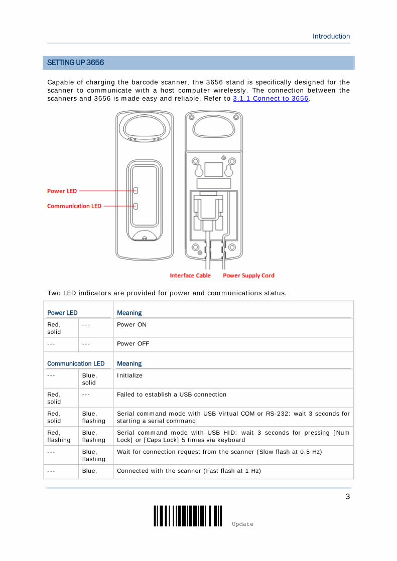
Capable of charging the barcode scanner, the 3656 stand is specifically designed for the scanner to communicate with a host computer wirelessly. The connection between the scanners and 3656 is made easy and reliable. Refer to 3.1.1 Connect to 3656.
Two LED indicators are provided for power and communications status.
Power LED Meaning
Red, solid
--- Power ON
--- --- Power OFF
Communication LED Meaning
--- Blue, solid
Initialize
Red, solid
--- Failed to establish a USB connection
Red, solid
Blue, flashing
Serial command mode with USB Virtual COM or RS-232: wait 3 seconds for starting a serial command
Red, flashing
Blue, flashing
Serial command mode with USB HID: wait 3 seconds for pressing [Num Lock] or [Caps Lock] 5 times via keyboard
--- Blue, flashing
Wait for connection request from the scanner (Slow flash at 0.5 Hz)
--- Blue, Connected with the scanner (Fast flash at 1 Hz)

4
Enter Setup
1564A Barcode Scanner User Guide
flashing
Red, solid
Blue, flashing
Failed to send data to host via USB Virtual COM (Fast flash at 1 Hz)
Red, flashing
--- Enter Download Mode
5
Update
Introduction
CHARGING THE BATTERY VIA 3656
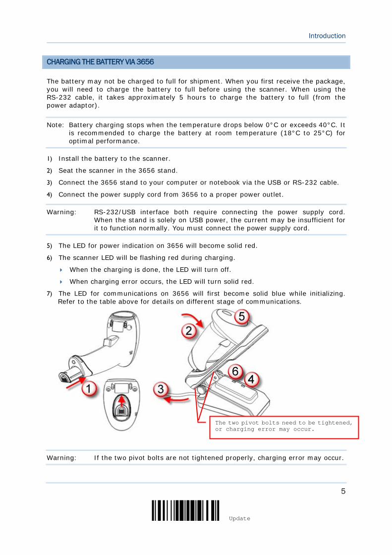
The battery may not be charged to full for shipment. When you first receive the package, you will need to charge the battery to full before using the scanner. When using the RS-232 cable, it takes approximately 5 hours to charge the battery to full (from the power adaptor).
Note: Battery charging stops when the temperature drops below 0°C or exceeds 40°C. It is recommended to charge the battery at room temperature (18°C to 25°C) for optimal performance.
1) Install the battery to the scanner.
2) Seat the scanner in the 3656 stand.
3) Connect the 3656 stand to your computer or notebook via the USB or RS-232 cable.
4) Connect the power supply cord from 3656 to a proper power outlet.
Warning: RS-232/USB interface both require connecting the power supply cord. When the stand is solely on USB power, the current may be insufficient for it to function normally. You must connect the power supply cord.
5) The LED for power indication on 3656 will become solid red.
6) The scanner LED will be flashing red during charging.
When the charging is done, the LED will turn off.
When charging error occurs, the LED will turn solid red.
7) The LED for communications on 3656 will first become solid blue while initializing. Refer to the table above for details on different stage of communications.
Warning: If the two pivot bolts are not tightened properly, charging error may occur.
The two pivot bolts need to be tightened, or charging error may occur.

6
Enter Setup
1564A Barcode Scanner User Guide
CHARGING THE BATTERY VIA CHARGER
The battery charger is provided for charging the battery only. You may purchase the charger separately. It takes approximately 3 hours to charge the battery to full.
Note: Battery charging stops when the temperature drops below 0°C or exceeds 40°C. It is recommended to charge the battery at room temperature (18°C to 25°C) for optimal performance.
1) Insert the battery.
2) Lock the battery.
3) Connect the power supply cord to the charger.
4) Connect the other end of the power cord to a suitable power outlet.
Status LED Meaning
Red, solid
--- Charger power ON (LED on for 0.5 second)
Red, solid
--- Charging battery
--- Green, solid
Charging done
Red, solid
Green, solid
Pre-charging when battery voltage under 3V (Typical)
--- --- Power or battery not ready
7
Update
Introduction
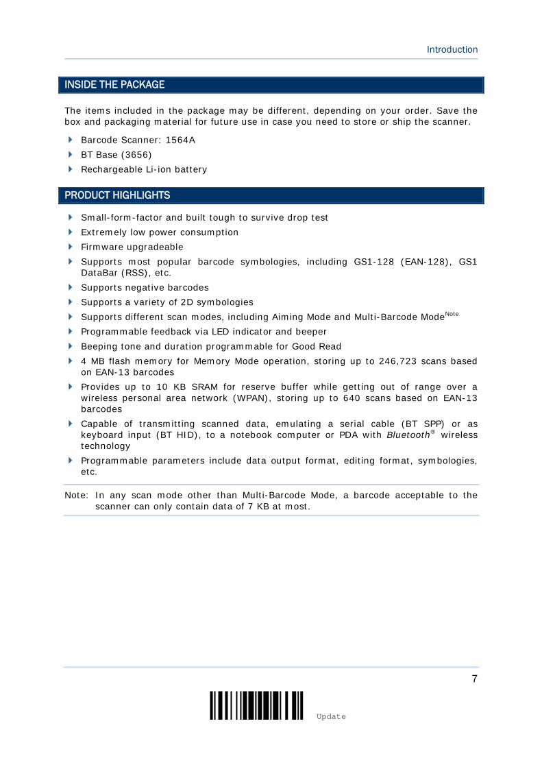
INSIDE THE PACKAGE
The items included in the package may be different, depending on your order. Save the box and packaging material for future use in case you need to store or ship the scanner.
Barcode Scanner: 1564A BT Base (3656) Rechargeable Li-ion battery
PRODUCT HIGHLIGHTS
Small-form-factor and built tough to survive drop test Extremely low power consumption Firmware upgradeable Supports most popular barcode symbologies, including GS1-128 (EAN-128), GS1
DataBar (RSS), etc. Supports negative barcodes Supports a variety of 2D symbologies Supports different scan modes, including Aiming Mode and Multi-Barcode ModeNote Programmable feedback via LED indicator and beeper Beeping tone and duration programmable for Good Read 4 MB flash memory for Memory Mode operation, storing up to 246,723 scans based
on EAN-13 barcodes Provides up to 10 KB SRAM for reserve buffer while getting out of range over a
wireless personal area network (WPAN), storing up to 640 scans based on EAN-13 barcodes
Capable of transmitting scanned data, emulating a serial cable (BT SPP) or as keyboard input (BT HID), to a notebook computer or PDA with Bluetooth® wireless technology
Programmable parameters include data output format, editing format, symbologies, etc.
Note: In any scan mode other than Multi-Barcode Mode, a barcode acceptable to the scanner can only contain data of 7 KB at most.
8
Enter Setup
1564A Barcode Scanner User Guide
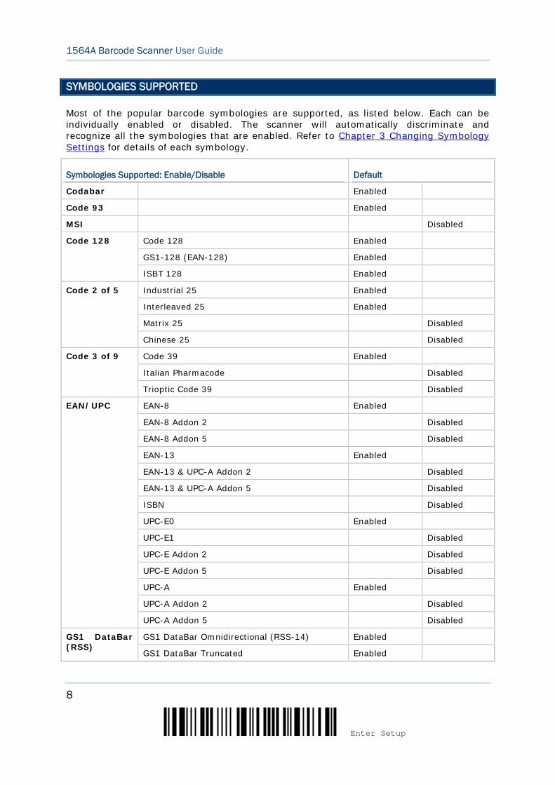
SYMBOLOGIES SUPPORTED
Most of the popular barcode symbologies are supported, as listed below. Each can be individually enabled or disabled. The scanner will automatically discriminate and recognize all the symbologies that are enabled. Refer to Chapter 3 Changing Symbology Settings for details of each symbology.
Symbologies Supported: Enable/Disable Default
Codabar Enabled
Code 93 Enabled
MSI Disabled
Code 128 Code 128 Enabled
GS1-128 (EAN-128) Enabled
ISBT 128 Enabled
Code 2 of 5 Industrial 25 Enabled
Interleaved 25 Enabled
Matrix 25 Disabled
Chinese 25 Disabled
Code 3 of 9 Code 39 Enabled
Italian Pharmacode Disabled
Trioptic Code 39 Disabled
EAN/UPC EAN-8 Enabled
EAN-8 Addon 2 Disabled
EAN-8 Addon 5 Disabled
EAN-13 Enabled
EAN-13 & UPC-A Addon 2 Disabled
EAN-13 & UPC-A Addon 5 Disabled
ISBN Disabled
UPC-E0 Enabled
UPC-E1 Disabled
UPC-E Addon 2 Disabled
UPC-E Addon 5 Disabled
UPC-A Enabled
UPC-A Addon 2 Disabled
UPC-A Addon 5 Disabled
GS1 DataBar (RSS)
GS1 DataBar Omnidirectional (RSS-14) Enabled
GS1 DataBar Truncated Enabled
9
Update
Introduction
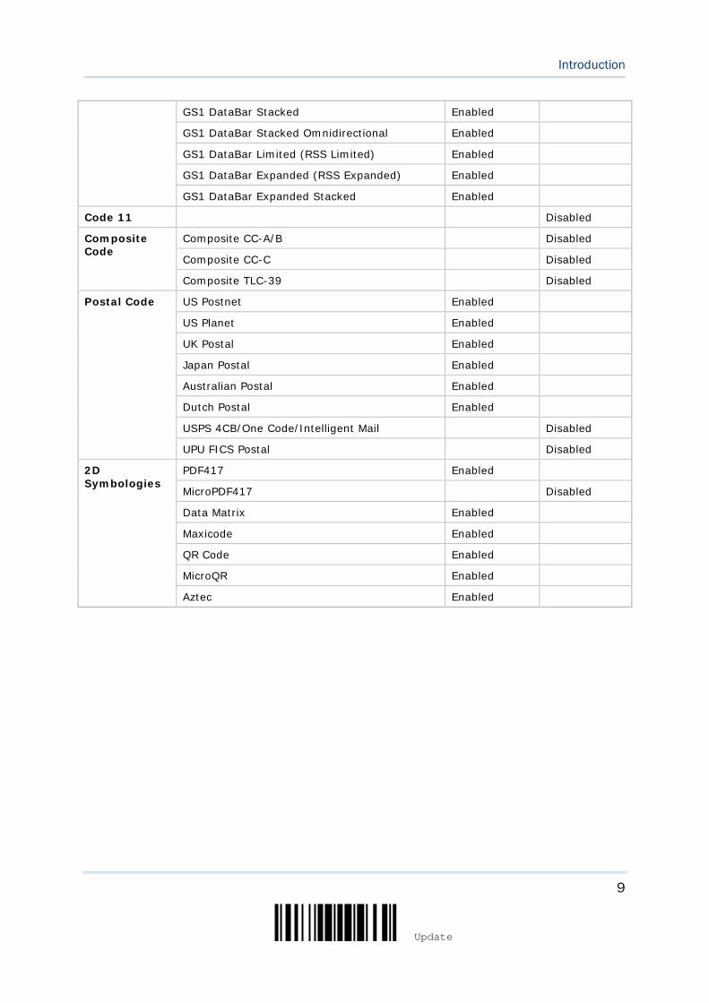
GS1 DataBar Stacked Enabled
GS1 DataBar Stacked Omnidirectional Enabled
GS1 DataBar Limited (RSS Limited) Enabled
GS1 DataBar Expanded (RSS Expanded) Enabled
GS1 DataBar Expanded Stacked Enabled
Code 11 Disabled
Composite Code
Composite CC-A/B Disabled
Composite CC-C Disabled
Composite TLC-39 Disabled
Postal Code US Postnet Enabled
US Planet Enabled
UK Postal Enabled
Japan Postal Enabled
Australian Postal Enabled
Dutch Postal Enabled
USPS 4CB/One Code/Intelligent Mail Disabled
UPU FICS Postal Disabled
2D Symbologies
PDF417 Enabled
MicroPDF417 Disabled
Data Matrix Enabled
Maxicode Enabled
QR Code Enabled
MicroQR Enabled
Aztec Enabled

10
Enter Setup
1564A Barcode Scanner User Guide
11
Update
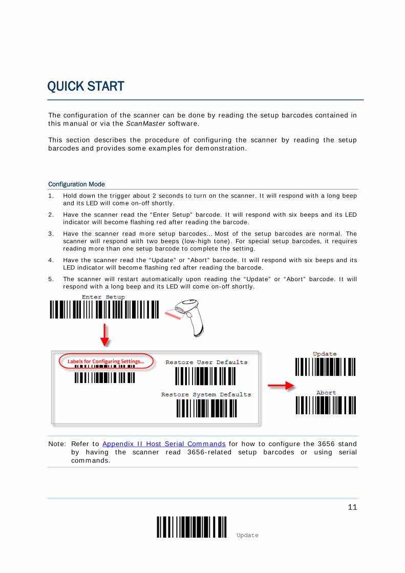
The configuration of the scanner can be done by reading the setup barcodes contained in this manual or via the ScanMaster software.
This section describes the procedure of configuring the scanner by reading the setup barcodes and provides some examples for demonstration.
Configuration Mode
1. Hold down the trigger about 2 seconds to turn on the scanner. It will respond with a long beep and its LED will come on-off shortly.
2. Have the scanner read the “Enter Setup” barcode. It will respond with six beeps and its LED indicator will become flashing red after reading the barcode.
3. Have the scanner read more setup barcodes… Most of the setup barcodes are normal. The scanner will respond with two beeps (low-high tone). For special setup barcodes, it requires reading more than one setup barcode to complete the setting.
4. Have the scanner read the “Update” or “Abort” barcode. It will respond with six beeps and its LED indicator will become flashing red after reading the barcode.
5. The scanner will restart automatically upon reading the “Update” or “Abort” barcode. It will respond with a long beep and its LED will come on-off shortly.
Note: Refer to Appendix II Host Serial Commands for how to configure the 3656 stand by having the scanner read 3656-related setup barcodes or using serial commands.
QUICK START
12
Enter Setup
1564A Barcode Scanner User Guide
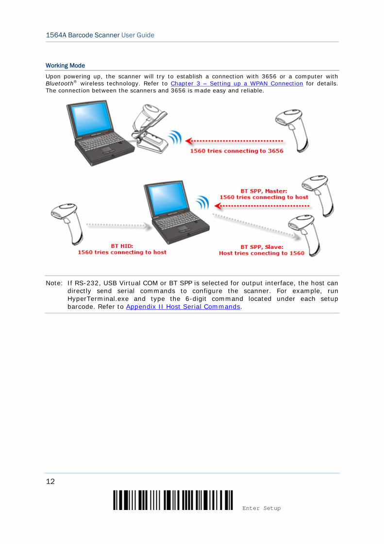
Working Mode
Upon powering up, the scanner will try to establish a connection with 3656 or a computer with Bluetooth® wireless technology. Refer to Chapter 3 – Setting up a WPAN Connection for details. The connection between the scanners and 3656 is made easy and reliable.
Note: If RS-232, USB Virtual COM or BT SPP is selected for output interface, the host can directly send serial commands to configure the scanner. For example, run HyperTerminal.exe and type the 6-digit command located under each setup barcode. Refer to Appendix II Host Serial Commands.
13
Update
Quick Start
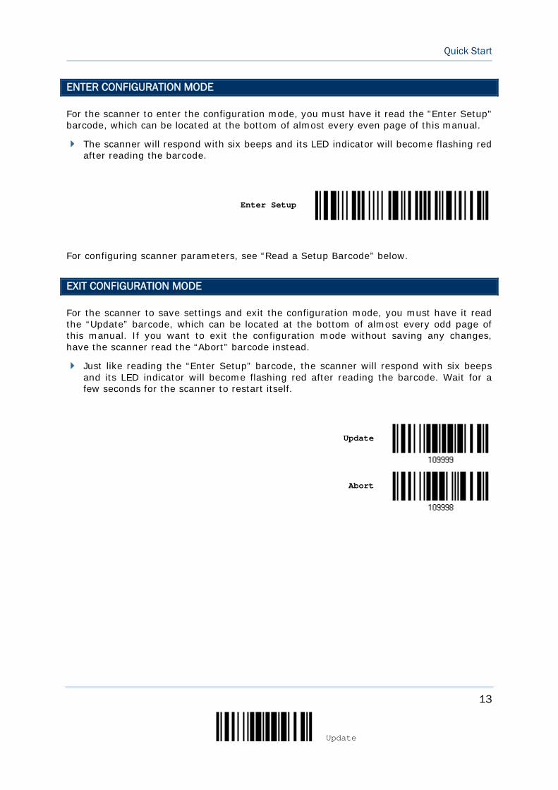
ENTER CONFIGURATION MODE
For the scanner to enter the configuration mode, you must have it read the "Enter Setup" barcode, which can be located at the bottom of almost every even page of this manual.
The scanner will respond with six beeps and its LED indicator will become flashing red after reading the barcode.
Enter Setup
For configuring scanner parameters, see “Read a Setup Barcode” below.
EXIT CONFIGURATION MODE
For the scanner to save settings and exit the configuration mode, you must have it read the “Update” barcode, which can be located at the bottom of almost every odd page of this manual. If you want to exit the configuration mode without saving any changes, have the scanner read the “Abort” barcode instead.
Just like reading the “Enter Setup” barcode, the scanner will respond with six beeps and its LED indicator will become flashing red after reading the barcode. Wait for a few seconds for the scanner to restart itself.
Update
Abort
14
Enter Setup
1564A Barcode Scanner User Guide
DEFAULT SETTINGS
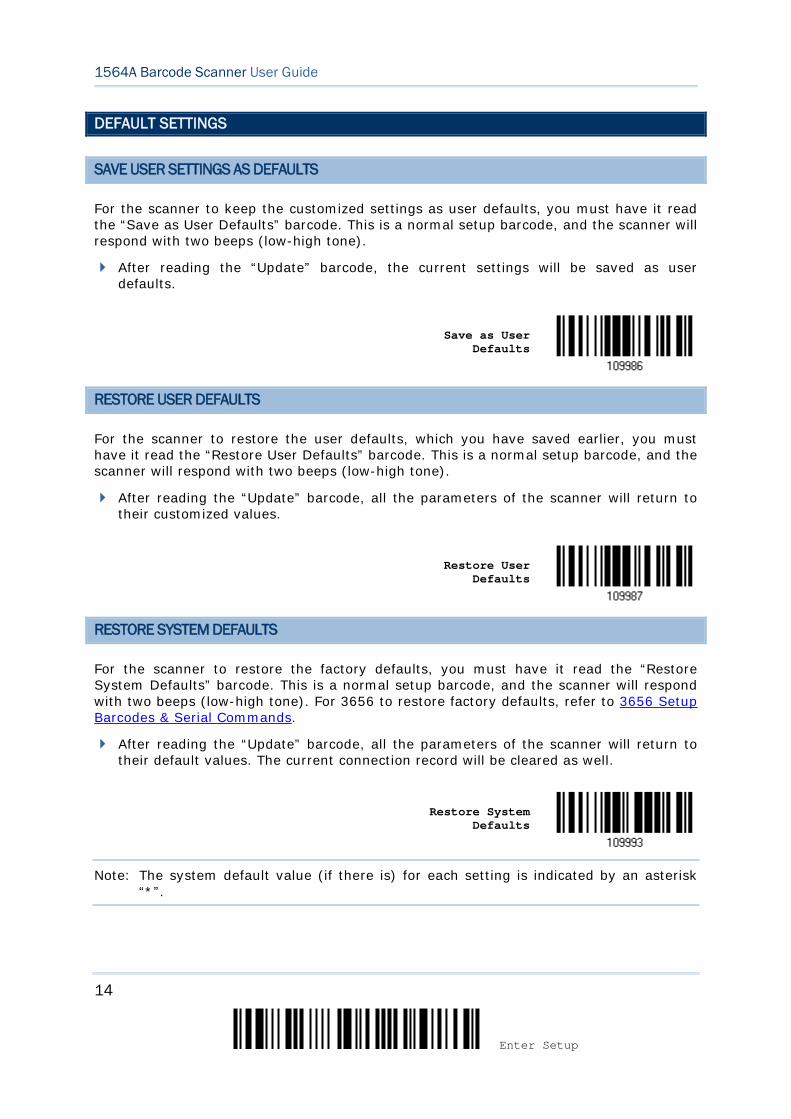
SAVE USER SETTINGS AS DEFAULTS
For the scanner to keep the customized settings as user defaults, you must have it read the “Save as User Defaults” barcode. This is a normal setup barcode, and the scanner will respond with two beeps (low-high tone).
After reading the “Update” barcode, the current settings will be saved as user defaults.
Save as User
Defaults
RESTORE USER DEFAULTS
For the scanner to restore the user defaults, which you have saved earlier, you must have it read the “Restore User Defaults” barcode. This is a normal setup barcode, and the scanner will respond with two beeps (low-high tone).
After reading the “Update” barcode, all the parameters of the scanner will return to their customized values.
Restore User
Defaults
RESTORE SYSTEM DEFAULTS
For the scanner to restore the factory defaults, you must have it read the “Restore System Defaults” barcode. This is a normal setup barcode, and the scanner will respond with two beeps (low-high tone). For 3656 to restore factory defaults, refer to 3656 Setup Barcodes & Serial Commands.
After reading the “Update” barcode, all the parameters of the scanner will return to their default values. The current connection record will be cleared as well.
Restore System
Defaults
Note: The system default value (if there is) for each setting is indicated by an asterisk “*”.
15
Update
Quick Start
READ A SETUP BARCODE
CONFIGURE PARAMETERS
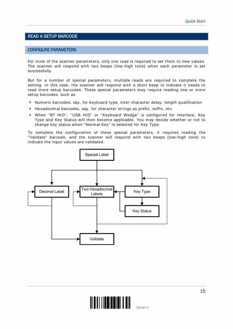
For most of the scanner parameters, only one read is required to set them to new values. The scanner will respond with two beeps (low-high tone) when each parameter is set successfully.
But for a number of special parameters, multiple reads are required to complete the setting. In this case, the scanner will respond with a short beep to indicate it needs to read more setup barcodes. These special parameters may require reading one or more setup barcodes, such as
Numeric barcodes, say, for keyboard type, inter-character delay, length qualification Hexadecimal barcodes, say, for character strings as prefix, suffix, etc. When “BT HID”, “USB HID” or “Keyboard Wedge” is configured for interface, Key
Type and Key Status will then become applicable. You may decide whether or not to change key status when “Normal Key” is selected for Key Type.
To complete the configuration of these special parameters, it requires reading the “Validate” barcode, and the scanner will respond with two beeps (low-high tone) to indicate the input values are validated.
16
Enter Setup
1564A Barcode Scanner User Guide
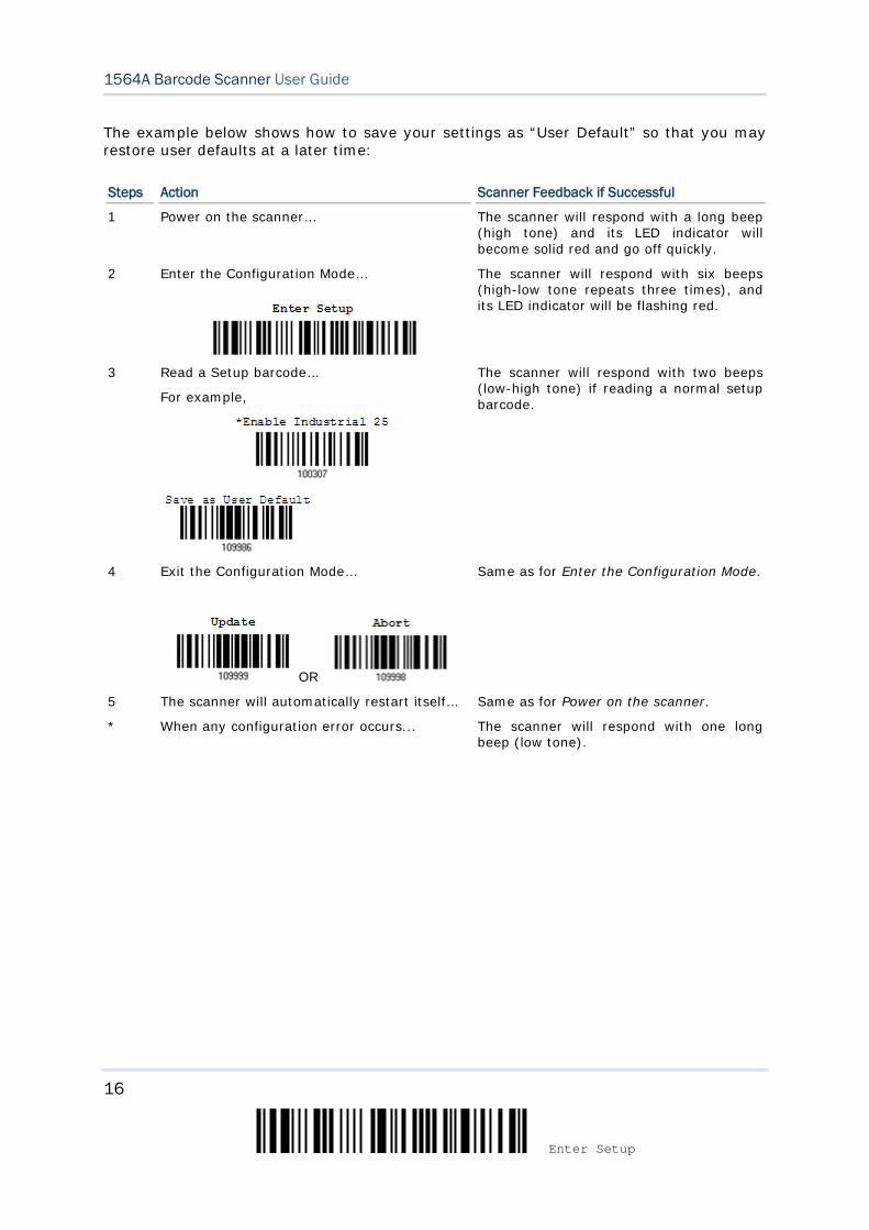
The example below shows how to save your settings as “User Default” so that you may restore user defaults at a later time:
Steps Action Scanner Feedback if Successful
1 Power on the scanner… The scanner will respond with a long beep (high tone) and its LED indicator will become solid red and go off quickly.
2 Enter the Configuration Mode…
The scanner will respond with six beeps (high-low tone repeats three times), and its LED indicator will be flashing red.
3 Read a Setup barcode…
For example,
The scanner will respond with two beeps (low-high tone) if reading a normal setup barcode.
4 Exit the Configuration Mode…
OR
Same as for Enter the Configuration Mode.
5 The scanner will automatically restart itself… Same as for Power on the scanner.
* When any configuration error occurs...
The scanner will respond with one long beep (low tone).
17
Update
Quick Start
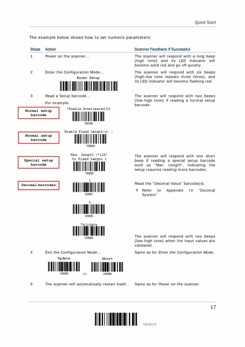
The example below shows how to set numeric parameters:
Steps Action Scanner Feedback if Successful
1 Power on the scanner... The scanner will respond with a long beep (high tone) and its LED indicator will become solid red and go off quickly.
2 Enter the Configuration Mode…
The scanner will respond with six beeps (high-low tone repeats three times), and its LED indicator will become flashing red.
3 Read a Setup barcode...
For example,
The scanner will respond with two beeps (low-high tone) if reading a normal setup barcode.
The scanner will respond with one short beep if reading a special setup barcode such as “Max. Length”, indicating the setup requires reading more barcodes.
Read the “Decimal Value” barcode(s).
Refer to Appendix IV “Decimal System”
The scanner will respond with two beeps (low-high tone) when the input values are validated.
4 Exit the Configuration Mode…
OR
Same as for Enter the Configuration Mode.
5 The scanner will automatically restart itself… Same as for Power on the scanner.
Normal setup barcode
Normal setup barcode
Special setup barcode
Decimal barcodes
18
Enter Setup
1564A Barcode Scanner User Guide
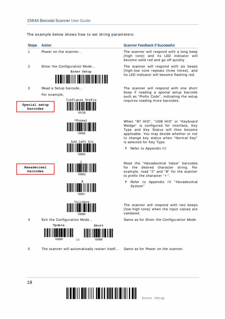
The example below shows how to set string parameters:
Steps Action Scanner Feedback if Successful
1 Power on the scanner... The scanner will respond with a long beep (high tone) and its LED indicator will become solid red and go off quickly.
2 Enter the Configuration Mode…
The scanner will respond with six beeps (high-low tone repeats three times), and its LED indicator will become flashing red.
3 Read a Setup barcode...
For example,
The scanner will respond with one short beep if reading a special setup barcode such as “Prefix Code”, indicating the setup requires reading more barcodes.
When “BT HID”, “USB HID” or “Keyboard Wedge” is configured for interface, Key Type and Key Status will then become applicable. You may decide whether or not to change key status when “Normal Key” is selected for Key Type.
Refer to Appendix III
Read the “Hexadecimal Value” barcodes for the desired character string. For example, read “2” and “B” for the scanner to prefix the character “+”.
Refer to Appendix IV “Hexadecimal System”
The scanner will respond with two beeps (low-high tone) when the input values are validated.
4 Exit the Configuration Mode…
OR
Same as for Enter the Configuration Mode.
5 The scanner will automatically restart itself… Same as for Power on the scanner.
Special setup barcodes
Hexadecimal barcodes
19
Update
Quick Start
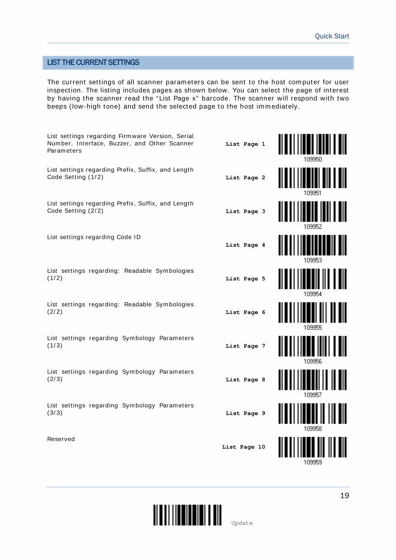
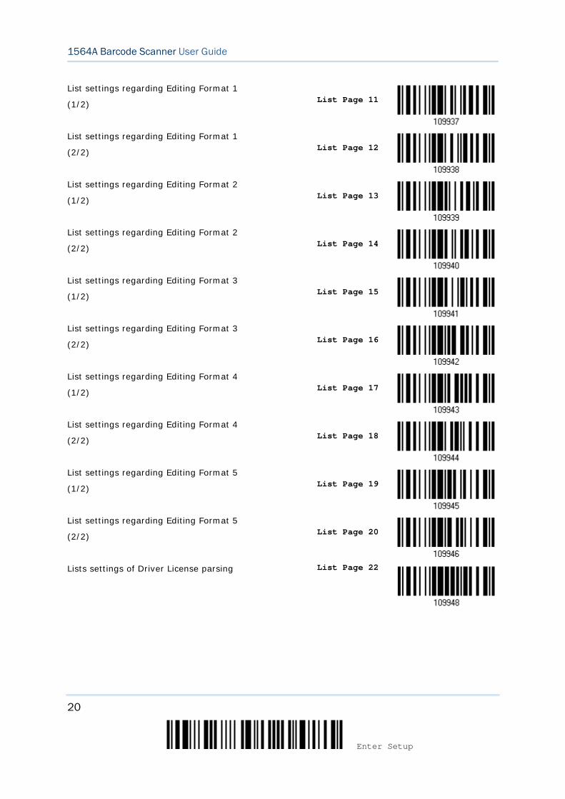
LIST THE CURRENT SETTINGS
The current settings of all scanner parameters can be sent to the host computer for user inspection. The listing includes pages as shown below. You can select the page of interest by having the scanner read the “List Page x” barcode. The scanner will respond with two beeps (low-high tone) and send the selected page to the host immediately.
List settings regarding Firmware Version, Serial Number, Interface, Buzzer, and Other Scanner Parameters
List Page 1
List settings regarding Prefix, Suffix, and Length Code Setting (1/2)
List Page 2
List settings regarding Prefix, Suffix, and Length Code Setting (2/2)
List Page 3
List settings regarding Code ID
List Page 4
List settings regarding: Readable Symbologies (1/2)
List Page 5
List settings regarding: Readable Symbologies (2/2)
List Page 6
List settings regarding Symbology Parameters (1/3)
List Page 7
List settings regarding Symbology Parameters (2/3)
List Page 8
List settings regarding Symbology Parameters (3/3)
List Page 9
Reserved
List Page 10
20
Enter Setup
1564A Barcode Scanner User Guide
List settings regarding Editing Format 1
(1/2)
List Page 11
List settings regarding Editing Format 1
(2/2)
List Page 12
List settings regarding Editing Format 2
(1/2)
List Page 13
List settings regarding Editing Format 2
(2/2)
List Page 14
List settings regarding Editing Format 3
(1/2)
List Page 15
List settings regarding Editing Format 3
(2/2)
List Page 16
List settings regarding Editing Format 4
(1/2)
List Page 17
List settings regarding Editing Format 4
(2/2)
List Page 18
List settings regarding Editing Format 5
(1/2)
List Page 19
List settings regarding Editing Format 5
(2/2)
List Page 20
Lists settings of Driver License parsing List Page 22
21
Update
Quick Start
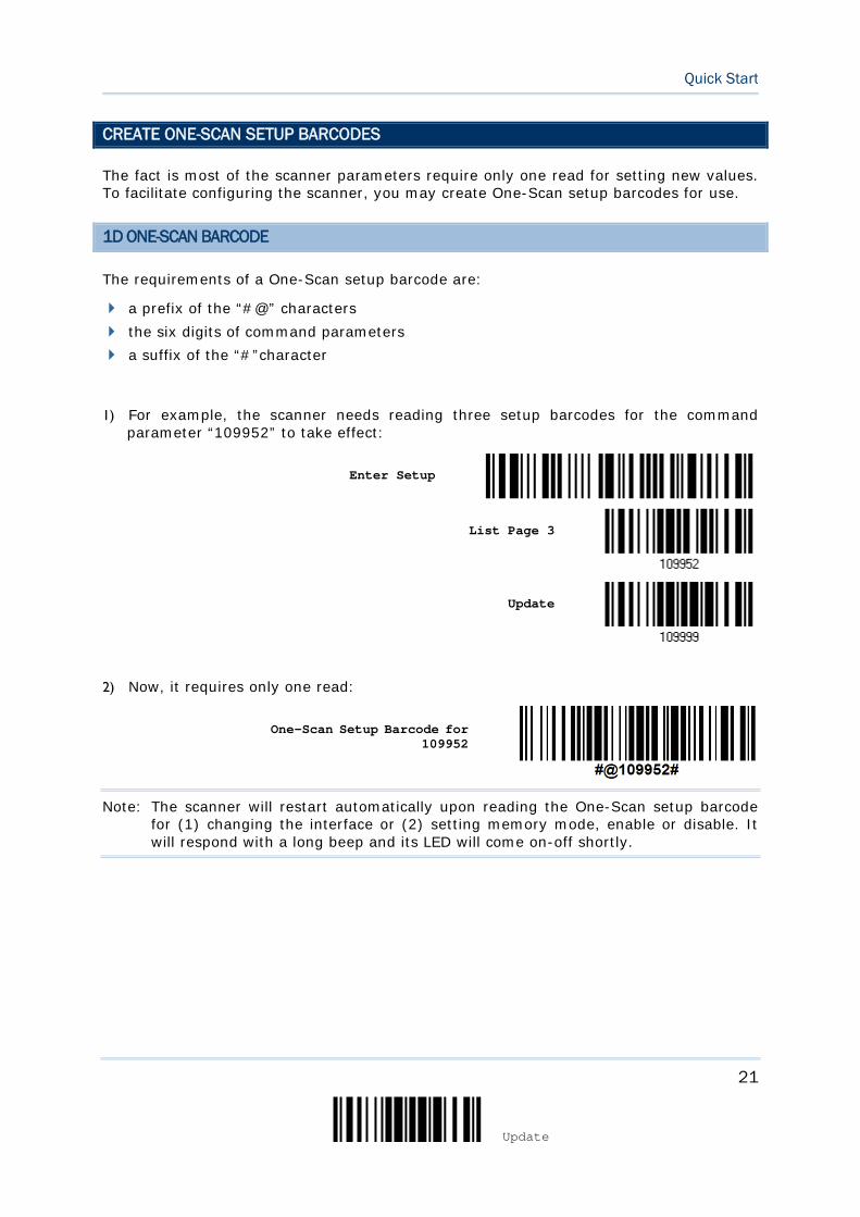
CREATE ONE-SCAN SETUP BARCODES
The fact is most of the scanner parameters require only one read for setting new values. To facilitate configuring the scanner, you may create One-Scan setup barcodes for use.
1D ONE-SCAN BARCODE
The requirements of a One-Scan setup barcode are:
a prefix of the “#@” characters the six digits of command parameters a suffix of the “#”character
1) For example, the scanner needs reading three setup barcodes for the command parameter “109952” to take effect:
Enter Setup
List Page 3
Update
2) Now, it requires only one read:
One-Scan Setup Barcode for 109952
Note: The scanner will restart automatically upon reading the One-Scan setup barcode for (1) changing the interface or (2) setting memory mode, enable or disable. It will respond with a long beep and its LED will come on-off shortly.
22
Enter Setup
1564A Barcode Scanner User Guide
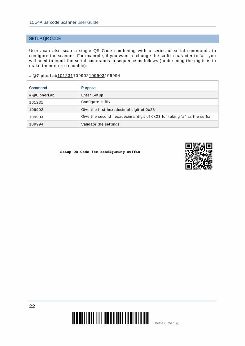
SETUP QR CODE
Users can also scan a single QR Code combining with a series of serial commands to configure the scanner. For example, if you want to change the suffix character to ‘#’, you will need to input the serial commands in sequence as follows (underlining the digits is to make them more readable):
#@CipherLab101231109902109903109994
Command Purpose
#@CipherLab Enter Setup
101231 Configure suffix
109902 Give the first hexadecimal digit of 0x23
109903 Give the second hexadecimal digit of 0x23 for taking ‘#’ as the suffix
109994 Validate the settings
Setup QR Code for configuring suffix
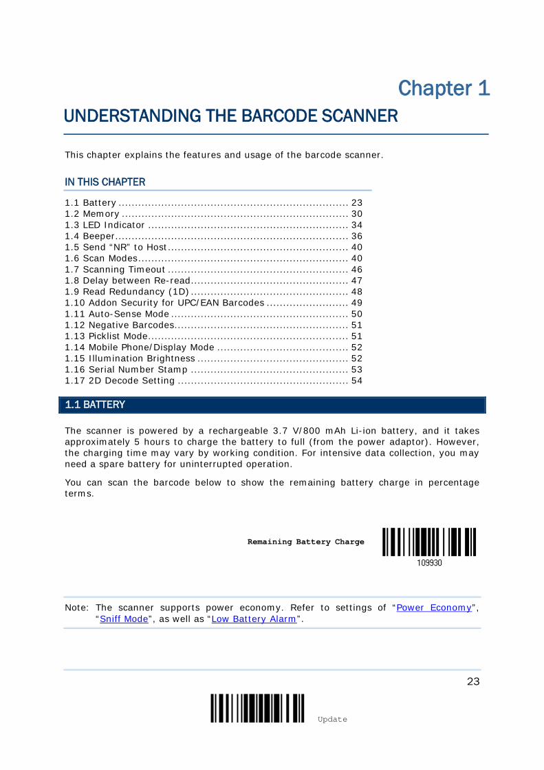
23
Update
This chapter explains the features and usage of the barcode scanner.
IN THIS CHAPTER
1.1 Battery ...................................................................... 23 1.2 Memory ..................................................................... 30 1.3 LED Indicator ............................................................. 34 1.4 Beeper....................................................................... 36 1.5 Send “NR” to Host ....................................................... 40 1.6 Scan Modes ................................................................ 40 1.7 Scanning Timeout ....................................................... 46 1.8 Delay between Re-read ................................................ 47 1.9 Read Redundancy (1D) ................................................ 48 1.10 Addon Security for UPC/EAN Barcodes ......................... 49 1.11 Auto-Sense Mode ...................................................... 50 1.12 Negative Barcodes..................................................... 51 1.13 Picklist Mode ............................................................. 51 1.14 Mobile Phone/Display Mode ........................................ 52 1.15 Illumination Brightness .............................................. 52 1.16 Serial Number Stamp ................................................ 53 1.17 2D Decode Setting .................................................... 54
1.1 BATTERY
The scanner is powered by a rechargeable 3.7 V/800 mAh Li-ion battery, and it takes approximately 5 hours to charge the battery to full (from the power adaptor). However, the charging time may vary by working condition. For intensive data collection, you may need a spare battery for uninterrupted operation.
You can scan the barcode below to show the remaining battery charge in percentage terms.
Remaining Battery Charge
Note: The scanner supports power economy. Refer to settings of “Power Economy”, “Sniff Mode”, as well as “Low Battery Alarm”.
Chapter 1 UNDERSTANDING THE BARCODE SCANNER

24
Enter Setup
1564A Barcode Scanner User Guide
1.1.1 TURN ON/OFF THE SCANNER
Turn on the scanner
After installing the battery, pull down the trigger for about 2 seconds. The scanner will respond with a long beep (high tone), then the LED will become solid red and go off quickly.
Turn on the scanner Automatically
For your convenience, the scanner is designed to power on automatically when you seat it in the stand connecting to the power socket. By default, this mechanism is disabled. You have to enable it by having the scanner read the Enable barcode below.
In this situation, the Auto Power Off function doesn’t work until the scanner is taken away from the stand.
Enable
*Disable
Turn off the scanner (by removing the battery)
Remove the battery directly or let it turn off automatically in specific circumstances.
Turn off the scanner (by pressing the trigger)
Or you can press down the scanner trigger for a specified time to turn off the scanner. Please enable this function and specify the time.
Enable
*Disable
By default, the scanner is turned off after you press the trigger for 5 seconds. Have the scanner to read one of the barcodes below to specify the time.
*Press Trigger for 5 seconds
Press Trigger for 10 seconds

25
Update
Chapter 1 Understanding the Barcode Scanner
Press Trigger for 15 seconds
Press Trigger for 20 seconds
Turn off the scanner (by scanning the barcode)
Scan the barcode below to turn off the scanner immediately.
Power Off
1.1.2 POWER ECONOMY
The scanner features “Power-Saving”, “Auto Power Off” and “Auto Power Off Ignoring Scan Mode” giving consideration to the power issue that is generally critical for Bluetooth-enabled devices. By the scanner’s support of power economy, its power consumption may progress by the following transition:
1) running at full CPU speed at power-on
2) shifting to low CPU speed (Power-Saving)
3) finally shutting down automatically (Auto Power Off)
26
Enter Setup
1564A Barcode Scanner User Guide
In the following content of this section, you will be guided through the configurations for the scanner’s power economy.
1.1.2.1 POWER-SAVING
For the scanner to save power, you need to appoint the timing for the scanner to shift to power-saving mode. Make the configuration that best suits your application while noting the following points:
Power-Saving: 1~254 minutes configurable. 0= Disable. By default, the scanner stands by at full-speed for 2 minutes after power-on and before entering low-speed mode. If Power-Saving isn’t desired, set it to 0 to disable it. Read the setup barcode in the following to achieve the setup.
Note: Power-Saving setting won’t take effect when the WPAN connection is established successfully whether via BT HID or SPP.
Power-Saving after
0~254 min. (*2)
1) Read the barcode above to enable the scanner to enter low-speed “Power-Saving”.
2) Assign the time for the scanner to enter low-speed mode by reading the “Decimal Value” barcode on page 275. For example, read “5” for the scanner to enter low-speed mode after idleness of 5 minutes.
3) Read the “Validate” barcode on the same page to complete this setting.
Note: Power-Saving won’t take effect when one of the following conditions is met: (1) the scanner has already established a BT HID/SPP connection, (2) the scanner is in the configuration mode, (3) the scan mode is set to Test Mode, (4) the setting value of Power-Saving is greater than that of Auto Power Off.
1.1.2.2 AUTO POWER OFF
Besides Power-Saving, users can also enable the Auto Power Off function to specify the time interval in minutes for the scanner to power itself off. Make the configuration that best suits your application while noting the following points:
Auto Power Off: 1~254 minutes configurable. 0= Disable.
1. By default, the scanner automatically shuts down 10 minutes after power-on.
2. If Auto Power Off isn’t desired, set the parameter to 0 to disable it.
27
Update
Chapter 1 Understanding the Barcode Scanner
3. When the scan mode is set to Test Mode, you need to enable “Auto Power Off Ignoring Scan Mode” in addition to enabling “Auto Power Off”. See the following section 1.1.2.3 Auto Power Off Ignoring Scan Mode.
Note: When the scanner is set to any scan mode other than Test Mode, you can ignore “Auto Power Off Ignoring Scan Mode”.
Auto Power Off after
0~254 min. (*10)
1) Read the barcode above to enable the scanner to automatically turn off at a specified
time after power-on.
2) Assign the auto power off time by reading the “Decimal Value” barcode on page 275. For example, read “1” and “5” for the scanner to automatically turn off after idleness of 15 minutes.
3) Read the “Validate” barcode on the same page to complete this setting.
Note: “Auto Power Off” will not take effect when the scanner is in the configuration mode.
28
Enter Setup
1564A Barcode Scanner User Guide
1.1.2.3 AUTO POWER OFF IGNORING SCAN MODE
This mode is intended only for Test Mode. To force a scanner that is set to Test Mode to automatically power off to save power, you need the following settings:
1. Enable “Auto Power Off” and set a time for the scanner to automatically power off after power-on. See the foregoing section 1.1.2.2 Auto Power Off
2. Enable “Auto Power Off Ignoring Scan Mode” by reading the barcode below:
Enable
*Disable
Read the barcode above to enable/disable automatic power-off for Test Mode.
Note: “Auto Power Off Ignoring Scan Mode” only features enabling and disabling. It doesn’t feature the setting of auto power-off time. Such setting should be configured in the preceding setup of “Auto Power Off”.
1.1.3 POWER ECONOMY VS. WPAN CONNECTION
Before the scanner can communicate with the host computer, Bluetooth connection (or WPAN connection) needs to be established. The scanner’s power economy always accommodates itself to the establishment of the WPAN connection.
The following describes how the scanner carries out power economy before and after the establishment of the WPAN connection:
Before establishing a WPAN connection successfully…
1. The scanner stays active for a specified period of time (2 minutes by default) for the following scenarios. The CPU runs at full speed, and the LED blinks blue (On/Off ratio 0.5 s: 0.5 s).
(a) waiting for a connection request from the host (BT SPP Slave Mode)
(b) trying to connect to the host (BT HID or BT SPP Master Mode)
(c) trying to connect to 3656
2. If the scanner fails to connect within 2 minutes, it becomes inactive to save power for the remaining period of time (the specified “Auto Power Off” value minus 2 minutes). The CPU starts to run at low speed, and the LED begins to blink red (On/Off ratio 0.3 s: 2.5 s).
Pull the trigger to wake up the scanner when it becomes inactive, and the scanner will become active again.
3. If it fails to connect again and again, and finally stays inactive until the specified Auto Power Off time elapses, the scanner will automatically turn off in order to conserve battery power.
29
Update
Chapter 1 Understanding the Barcode Scanner
Pull down the trigger for about 2 seconds to turn it on again.
Note: For scenarios (a) and (b) in step 1, you may need to search for the scanner again on your computer.
After establishing a WPAN connection successfully…
1. Once a WPAN connection is established successfully, the scanner will stay active for a specified period of time (2 minutes by default) for data transmission. The CPU runs at full speed, and the LED blinks blue (On/Off ratio 0.02 s: 3 s).
2. If the scanner stays idle for 2 minutes (default), it will then turn inactive to save power for the remaining period of time (the specified “Auto Power Off” value minus 2 minutes). The CPU runs at low speed, and the LED is blinking red (On/Off ratio 0.3 s: 2.5 s).
Pull the trigger to wake up the scanner when it becomes inactive, then the scanner will stay active again.
For BT HID or SPP, the scanner automatically shuts down after the configured “Auto Power Off” time without the transition from full CPU speed to low CPU speed. However, when connecting with 3656, the scanner will go through the transition in order to save power.
3. If the scanner first becomes idle and finally stays inactive until the specified Auto Power Off time is up, the scanner will automatically turn off in order to conserve battery power. You will hear three short beeps, tone descending from high to low.
Pull down the trigger for about 2 seconds to turn it on again.
For BT HID, the scanner resumes the connection with the host upon powering on again, as long as the host application is running. You will hear three short beeps, tone ascending from low to high upon the resumption. If the scanner fails to resume the connection, it will try every 5 seconds to re-connect to the host unless you have the scanner read the “Reset Connection” barcode.
For BT SPP Slave Mode, the scanner waits for the host to re-connect.
For BT SPP Master Mode, the scanner resumes the connection with the host upon powering on again as long as the host application is running. You will hear three short beeps, tone ascending from low to high upon resumption. If the scanner fails to resume the connection, it will try every 5 seconds to re-connect to the host unless you have the scanner read the “Reset Connection” or “Restore System Defaults” barcode.
With the use of 3656, the scanner tries to re-connect 3656 unless you turn off the scanner.
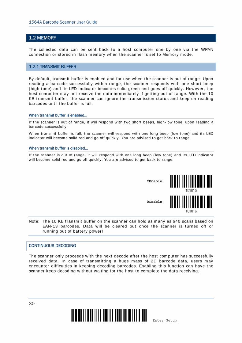
30
Enter Setup
1564A Barcode Scanner User Guide
1.2 MEMORY
The collected data can be sent back to a host computer one by one via the WPAN connection or stored in flash memory when the scanner is set to Memory mode.
1.2.1 TRANSMIT BUFFER
By default, transmit buffer is enabled and for use when the scanner is out of range. Upon reading a barcode successfully within range, the scanner responds with one short beep (high tone) and its LED indicator becomes solid green and goes off quickly. However, the host computer may not receive the data immediately if getting out of range. With the 10 KB transmit buffer, the scanner can ignore the transmission status and keep on reading barcodes until the buffer is full.
When transmit buffer is enabled…
If the scanner is out of range, it will respond with two short beeps, high-low tone, upon reading a barcode successfully.
When transmit buffer is full, the scanner will respond with one long beep (low tone) and its LED indicator will become solid red and go off quickly. You are advised to get back to range.
When transmit buffer is disabled…
If the scanner is out of range, it will respond with one long beep (low tone) and its LED indicator will become solid red and go off quickly. You are advised to get back to range.
*Enable
Disable
Note: The 10 KB transmit buffer on the scanner can hold as many as 640 scans based on EAN-13 barcodes. Data will be cleared out once the scanner is turned off or running out of battery power!
CONTINUOUS DECODING
The scanner only proceeds with the next decode after the host computer has successfully received data. In case of transmitting a huge mass of 2D barcode data, users may encounter difficulties in keeping decoding barcodes. Enabling this function can have the scanner keep decoding without waiting for the host to complete the data receiving.
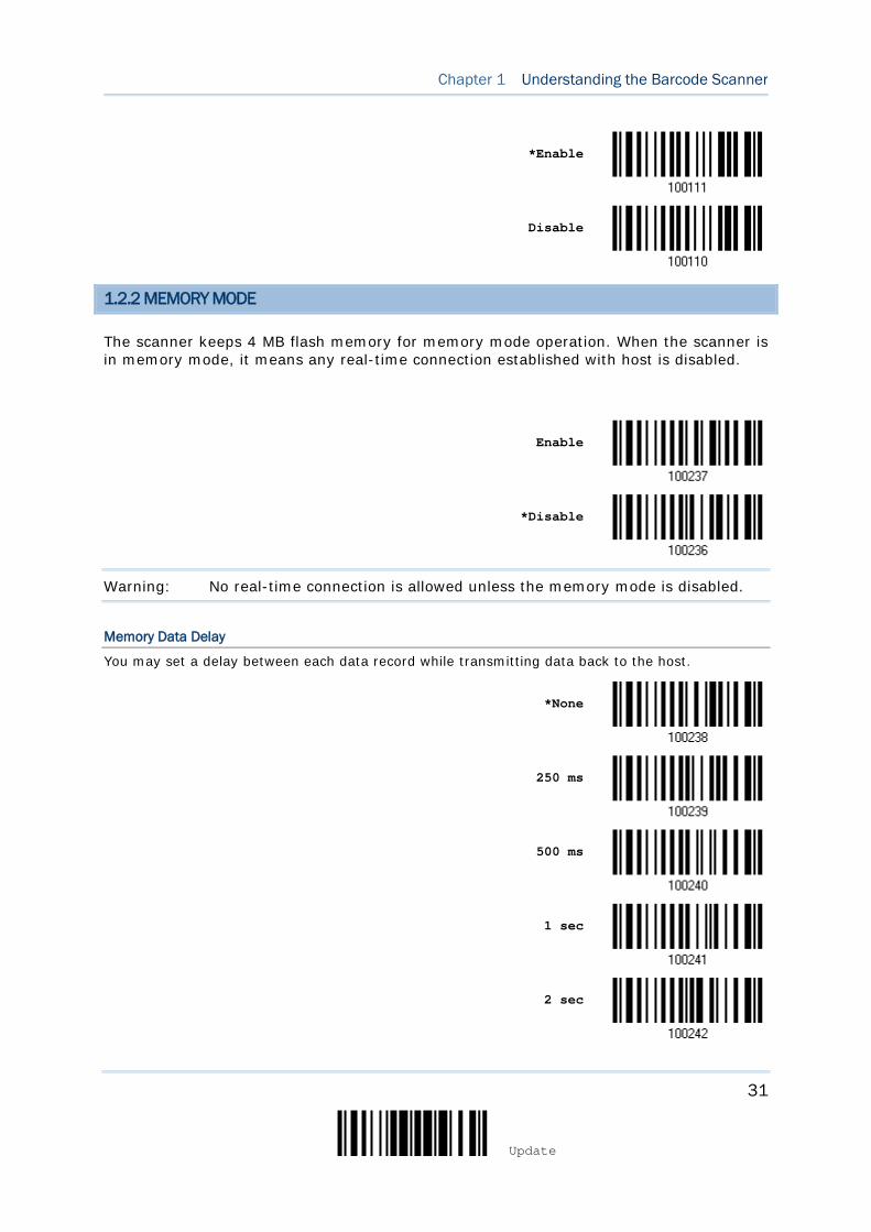
31
Update
Chapter 1 Understanding the Barcode Scanner
*Enable
Disable
1.2.2 MEMORY MODE
The scanner keeps 4 MB flash memory for memory mode operation. When the scanner is in memory mode, it means any real-time connection established with host is disabled.
Enable
*Disable
Warning: No real-time connection is allowed unless the memory mode is disabled.
Memory Data Delay
You may set a delay between each data record while transmitting data back to the host.
*None
250 ms
500 ms
1 sec
2 sec
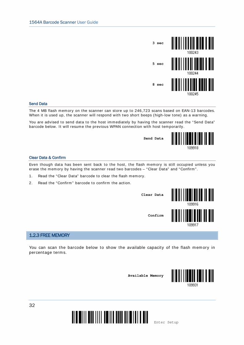
32
Enter Setup
1564A Barcode Scanner User Guide
3 sec
5 sec
8 sec
Send Data
The 4 MB flash memory on the scanner can store up to 246,723 scans based on EAN-13 barcodes. When it is used up, the scanner will respond with two short beeps (high-low tone) as a warning.
You are advised to send data to the host immediately by having the scanner read the “Send Data” barcode below. It will resume the previous WPAN connection with host temporarily.
Send Data
Clear Data & Confirm
Even though data has been sent back to the host, the flash memory is still occupied unless you erase the memory by having the scanner read two barcodes – “Clear Data” and “Confirm”.
1. Read the “Clear Data” barcode to clear the flash memory.
2. Read the “Confirm” barcode to confirm the action.
Clear Data
Confirm
1.2.3 FREE MEMORY
You can scan the barcode below to show the available capacity of the flash memory in percentage terms.
Available Memory

33
Update
Chapter 1 Understanding the Barcode Scanner
1.2.4 RECORD COUNT OF MEMORY
You can scan the barcode below to show the data record count of the flash memory.
Data Record Count of
Memory
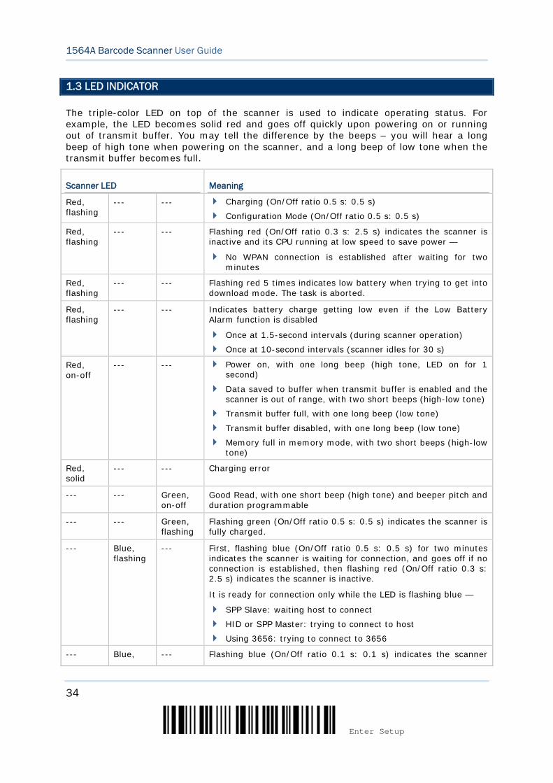
34
Enter Setup
1564A Barcode Scanner User Guide
1.3 LED INDICATOR
The triple-color LED on top of the scanner is used to indicate operating status. For example, the LED becomes solid red and goes off quickly upon powering on or running out of transmit buffer. You may tell the difference by the beeps – you will hear a long beep of high tone when powering on the scanner, and a long beep of low tone when the transmit buffer becomes full.
Scanner LED Meaning
Red, flashing
--- --- Charging (On/Off ratio 0.5 s: 0.5 s)
Configuration Mode (On/Off ratio 0.5 s: 0.5 s)
Red, flashing
--- --- Flashing red (On/Off ratio 0.3 s: 2.5 s) indicates the scanner is inactive and its CPU running at low speed to save power —
No WPAN connection is established after waiting for two minutes
Red, flashing
--- --- Flashing red 5 times indicates low battery when trying to get into download mode. The task is aborted.
Red, flashing
--- --- Indicates battery charge getting low even if the Low Battery Alarm function is disabled
Once at 1.5-second intervals (during scanner operation)
Once at 10-second intervals (scanner idles for 30 s)
Red, on-off
--- --- Power on, with one long beep (high tone, LED on for 1 second)
Data saved to buffer when transmit buffer is enabled and the scanner is out of range, with two short beeps (high-low tone)
Transmit buffer full, with one long beep (low tone)
Transmit buffer disabled, with one long beep (low tone)
Memory full in memory mode, with two short beeps (high-low tone)
Red, solid
--- --- Charging error
--- --- Green, on-off
Good Read, with one short beep (high tone) and beeper pitch and duration programmable
--- --- Green, flashing
Flashing green (On/Off ratio 0.5 s: 0.5 s) indicates the scanner is fully charged.
--- Blue, flashing
--- First, flashing blue (On/Off ratio 0.5 s: 0.5 s) for two minutes indicates the scanner is waiting for connection, and goes off if no connection is established, then flashing red (On/Off ratio 0.3 s: 2.5 s) indicates the scanner is inactive.
It is ready for connection only while the LED is flashing blue —
SPP Slave: waiting host to connect
HID or SPP Master: trying to connect to host
Using 3656: trying to connect to 3656
--- Blue, --- Flashing blue (On/Off ratio 0.1 s: 0.1 s) indicates the scanner
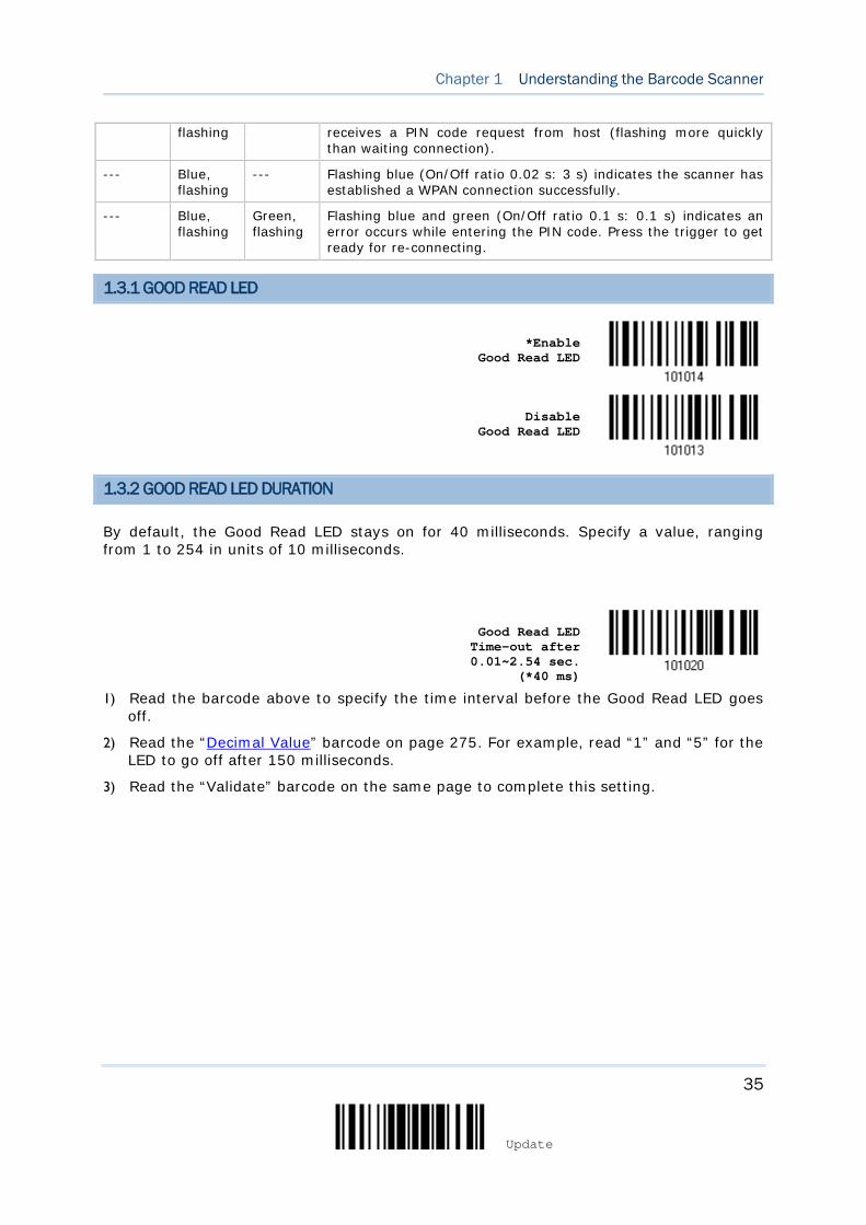
35
Update
Chapter 1 Understanding the Barcode Scanner
flashing receives a PIN code request from host (flashing more quickly than waiting connection).
--- Blue, flashing
--- Flashing blue (On/Off ratio 0.02 s: 3 s) indicates the scanner has established a WPAN connection successfully.
--- Blue, flashing
Green, flashing
Flashing blue and green (On/Off ratio 0.1 s: 0.1 s) indicates an error occurs while entering the PIN code. Press the trigger to get ready for re-connecting.
1.3.1 GOOD READ LED
*Enable
Good Read LED
Disable Good Read LED
1.3.2 GOOD READ LED DURATION
By default, the Good Read LED stays on for 40 milliseconds. Specify a value, ranging from 1 to 254 in units of 10 milliseconds.
Good Read LED Time-out after 0.01~2.54 sec.
(*40 ms)
1) Read the barcode above to specify the time interval before the Good Read LED goes off.
2) Read the “Decimal Value” barcode on page 275. For example, read “1” and “5” for the LED to go off after 150 milliseconds.
3) Read the “Validate” barcode on the same page to complete this setting.
36
Enter Setup
1564A Barcode Scanner User Guide
1.4 BEEPER
The scanner has a buzzer to give feedback for various operating conditions.
Beeping Meaning
One long beep, high tone Power on, with red LED on (1 second) and off quickly
One short beep, high tone
Programmable, default to 4 KHz
Good Read, with green LED on-off quickly
Six short beeps
High-low tone repeats three times
Enter Configuration Mode, with red LED flashing
Exit Configuration Mode
Two short beeps, low-high tone Setup barcode read successfully
One short beep, high tone More setup barcode required
Input PIN code
Clear PIN code
One short beep, low tone More barcodes required to complete the “output sequence” requirements of Multi-Barcode Editor, with green LED on-off quickly (Upon completion, same as Good Read.)
One long beep, low tone Transmit buffer full, with red LED on-off quickly
Transmit buffer disabled, with red LED on-off quickly
Configuration error (Wrong barcode…)
PIN code input error
Reject random PIN request
Fail to send data in memory mode
Two short beeps, high-low tone Data saved to buffer when transmit buffer is enabled and the scanner is out of range, with red LED on-off quickly
Memory Mode – Memory full, with red LED on-off quickly
Two short beeps, high tone Low Battery Alarm
One short beep then one long beep, high-low tone
Indicates low battery when trying to get into download mode. The task is aborted.
Two long beeps, high-low tone Multi-Barcode Mode – Buffer full
Three short beeps, tone ascending from low to high
WPAN connection established, with blue LED flashing
WPAN connection resumed, with blue LED flashing
Three short beeps, tone ascending from high to low
WPAN connection out of range or suspended
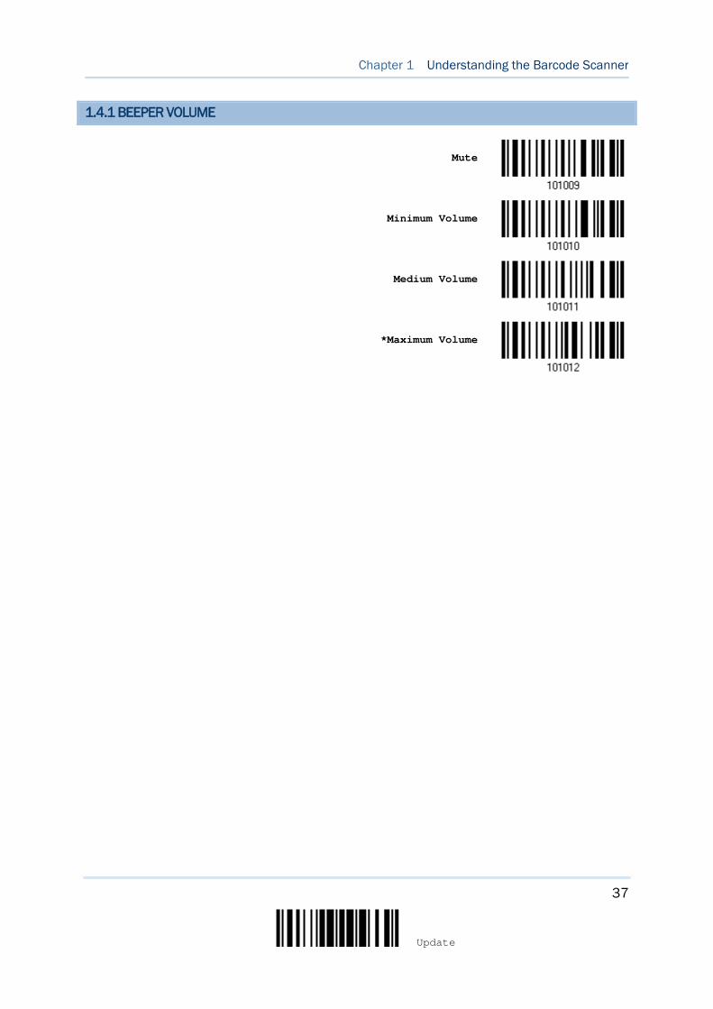
37
Update
Chapter 1 Understanding the Barcode Scanner
1.4.1 BEEPER VOLUME
Mute
Minimum Volume
Medium Volume
*Maximum Volume
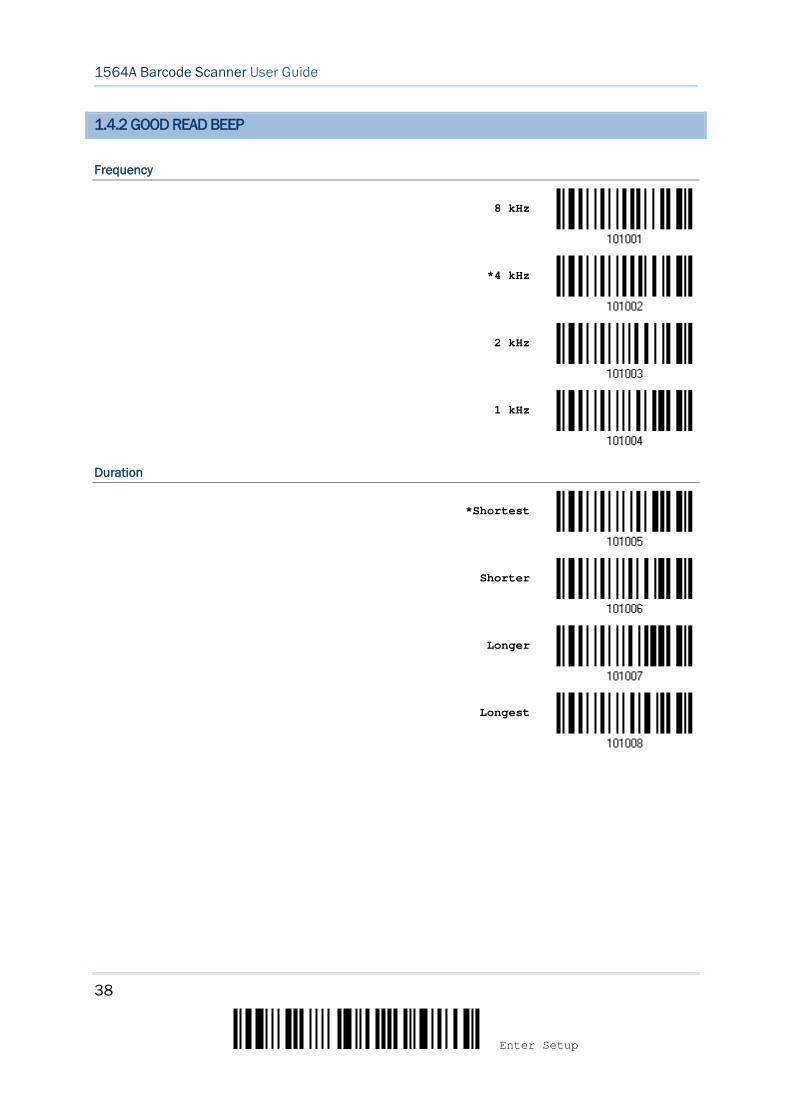
38
Enter Setup
1564A Barcode Scanner User Guide
1.4.2 GOOD READ BEEP
Frequency
8 kHz
*4 kHz
2 kHz
1 kHz
Duration
*Shortest
Shorter
Longer
Longest

39
Update
Chapter 1 Understanding the Barcode Scanner
1.4.3 LOW BATTERY ALARM
By default, the beeper is enabled to give a warning when the battery charge gets low. In order to prevent data loss, you are advised to replace the battery immediately when you hear two short beeps (high tone).
Low Battery Alarm Time Interval Description
1.5 seconds During scanner operation
10 seconds The scanner is left idle for 30 seconds
No Alarm
*Low Battery Alarm
1.4.4 BELL RING
With this function enabled, the scanner will produce a bell ring when receiving the ‘0x07’ character which is sent via BT SPP Slave, BT SPP Master, RS232 via BT cradle, VCOM via BT cradle, or VCOM CDC via BT cradle interface.
Enable
*Disable
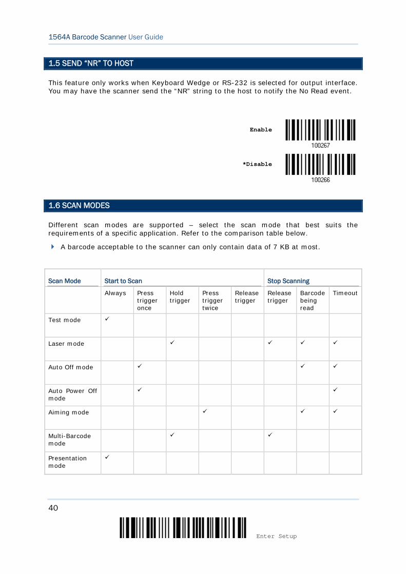
40
Enter Setup
1564A Barcode Scanner User Guide
1.5 SEND “NR” TO HOST
This feature only works when Keyboard Wedge or RS-232 is selected for output interface. You may have the scanner send the “NR” string to the host to notify the No Read event.
Enable
*Disable
1.6 SCAN MODES
Different scan modes are supported – select the scan mode that best suits the requirements of a specific application. Refer to the comparison table below.
A barcode acceptable to the scanner can only contain data of 7 KB at most.
Scan Mode Start to Scan Stop Scanning
Always Press trigger once
Hold trigger
Press trigger twice
Release trigger
Release trigger
Barcode being read
Timeout
Test mode
Laser mode
Auto Off mode
Auto Power Off mode
Aiming mode
Multi-Barcode mode
Presentation mode

41
Update
Chapter 1 Understanding the Barcode Scanner
Multicode mode
Release Mode
Note: By default, the scan mode is set to Laser mode.
1.6.1 TEST MODE
The scanner is always scanning.
Capable of decoding the same barcode repeatedly without removing it, for testing purpose.
Test Mode
1.6.2 LASER MODE
The scanner will start scanning once the trigger is held down.
The scanning won't stop until (1) a barcode is decoded, (2) the pre-set timeout expires, or (3) you release the trigger.
Note: Refer to 1.7 Scanning Timeout.
*Laser Mode
1.6.3 AUTO OFF MODE
The scanner will start scanning once the trigger is pressed.
The scanning won't stop until (1) a barcode is decoded, and (2) the pre-set timeout expires.
Note: Refer to 1.7 Scanning Timeout.
Auto Off Mode

42
Enter Setup
1564A Barcode Scanner User Guide
1.6.4 AUTO POWER OFF MODE
The scanner will start scanning once the trigger is pressed.
The scanning won't stop until the pre-set timeout expires, and, the pre-set timeout period re-counts after each successful decoding.
Note: Refer to 1.8 Delay between Re-read and 1.7 Scanning Timeout.
Auto Power Off Mode
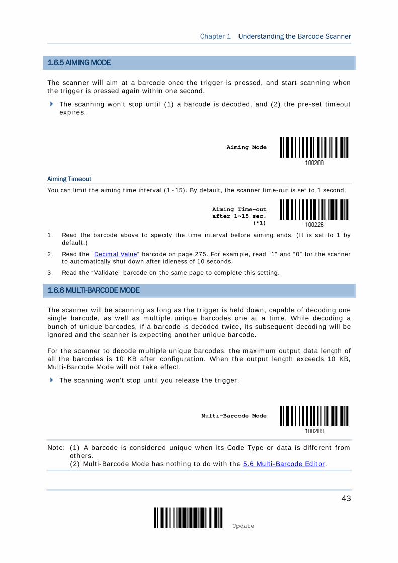
43
Update
Chapter 1 Understanding the Barcode Scanner
1.6.5 AIMING MODE
The scanner will aim at a barcode once the trigger is pressed, and start scanning when the trigger is pressed again within one second.
The scanning won't stop until (1) a barcode is decoded, and (2) the pre-set timeout expires.
Aiming Mode
Aiming Timeout
You can limit the aiming time interval (1~15). By default, the scanner time-out is set to 1 second.
Aiming Time-out after 1~15 sec.
(*1)
1. Read the barcode above to specify the time interval before aiming ends. (It is set to 1 by default.)
2. Read the “Decimal Value” barcode on page 275. For example, read “1” and “0” for the scanner to automatically shut down after idleness of 10 seconds.
3. Read the “Validate” barcode on the same page to complete this setting.
1.6.6 MULTI-BARCODE MODE
The scanner will be scanning as long as the trigger is held down, capable of decoding one single barcode, as well as multiple unique barcodes one at a time. While decoding a bunch of unique barcodes, if a barcode is decoded twice, its subsequent decoding will be ignored and the scanner is expecting another unique barcode.
For the scanner to decode multiple unique barcodes, the maximum output data length of all the barcodes is 10 KB after configuration. When the output length exceeds 10 KB, Multi-Barcode Mode will not take effect.
The scanning won't stop until you release the trigger.
Multi-Barcode Mode
Note: (1) A barcode is considered unique when its Code Type or data is different from others. (2) Multi-Barcode Mode has nothing to do with the 5.6 Multi-Barcode Editor.
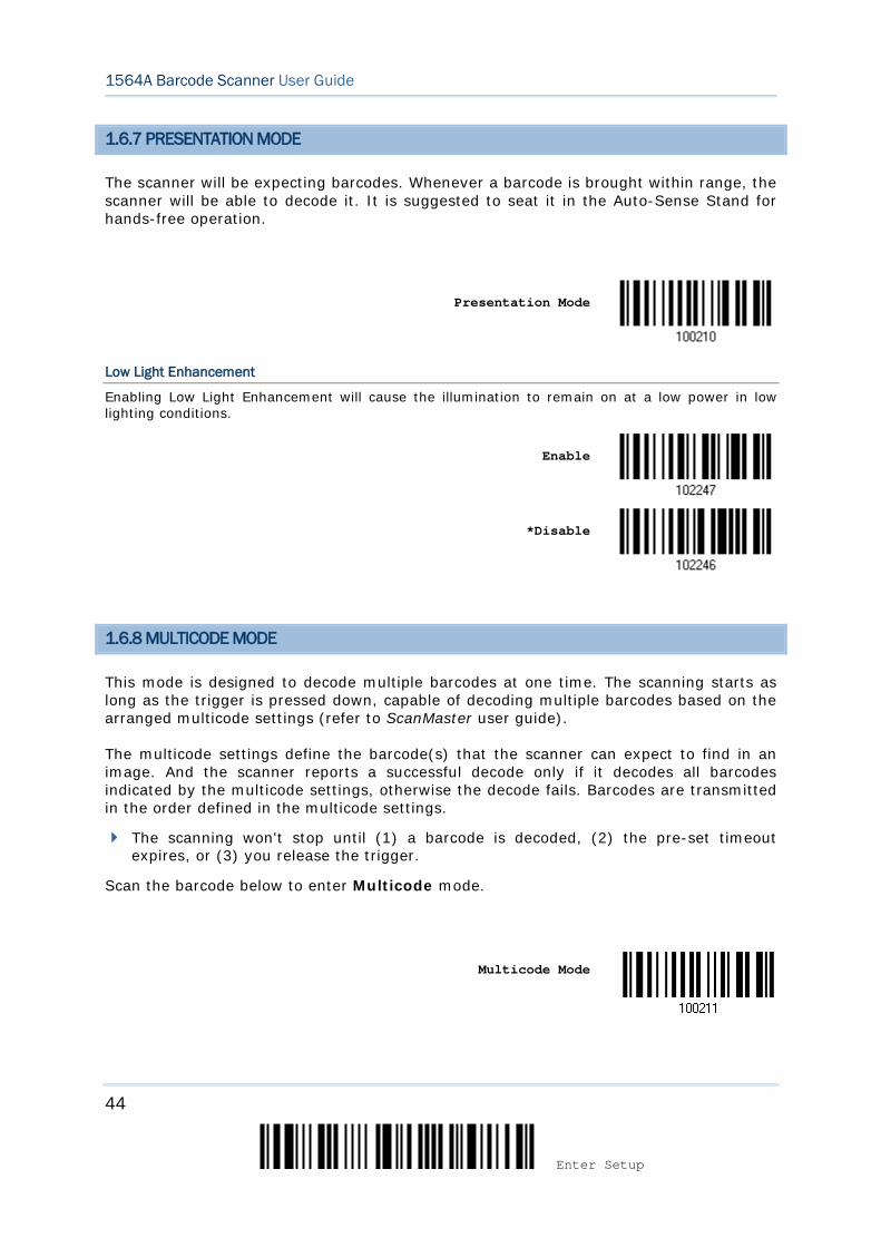
44
Enter Setup
1564A Barcode Scanner User Guide
1.6.7 PRESENTATION MODE
The scanner will be expecting barcodes. Whenever a barcode is brought within range, the scanner will be able to decode it. It is suggested to seat it in the Auto-Sense Stand for hands-free operation.
Presentation Mode
Low Light Enhancement
Enabling Low Light Enhancement will cause the illumination to remain on at a low power in low lighting conditions.
Enable
*Disable
1.6.8 MULTICODE MODE
This mode is designed to decode multiple barcodes at one time. The scanning starts as long as the trigger is pressed down, capable of decoding multiple barcodes based on the arranged multicode settings (refer to ScanMaster user guide).
The multicode settings define the barcode(s) that the scanner can expect to find in an image. And the scanner reports a successful decode only if it decodes all barcodes indicated by the multicode settings, otherwise the decode fails. Barcodes are transmitted in the order defined in the multicode settings.
The scanning won't stop until (1) a barcode is decoded, (2) the pre-set timeout expires, or (3) you release the trigger.
Scan the barcode below to enter Multicode mode.
Multicode Mode
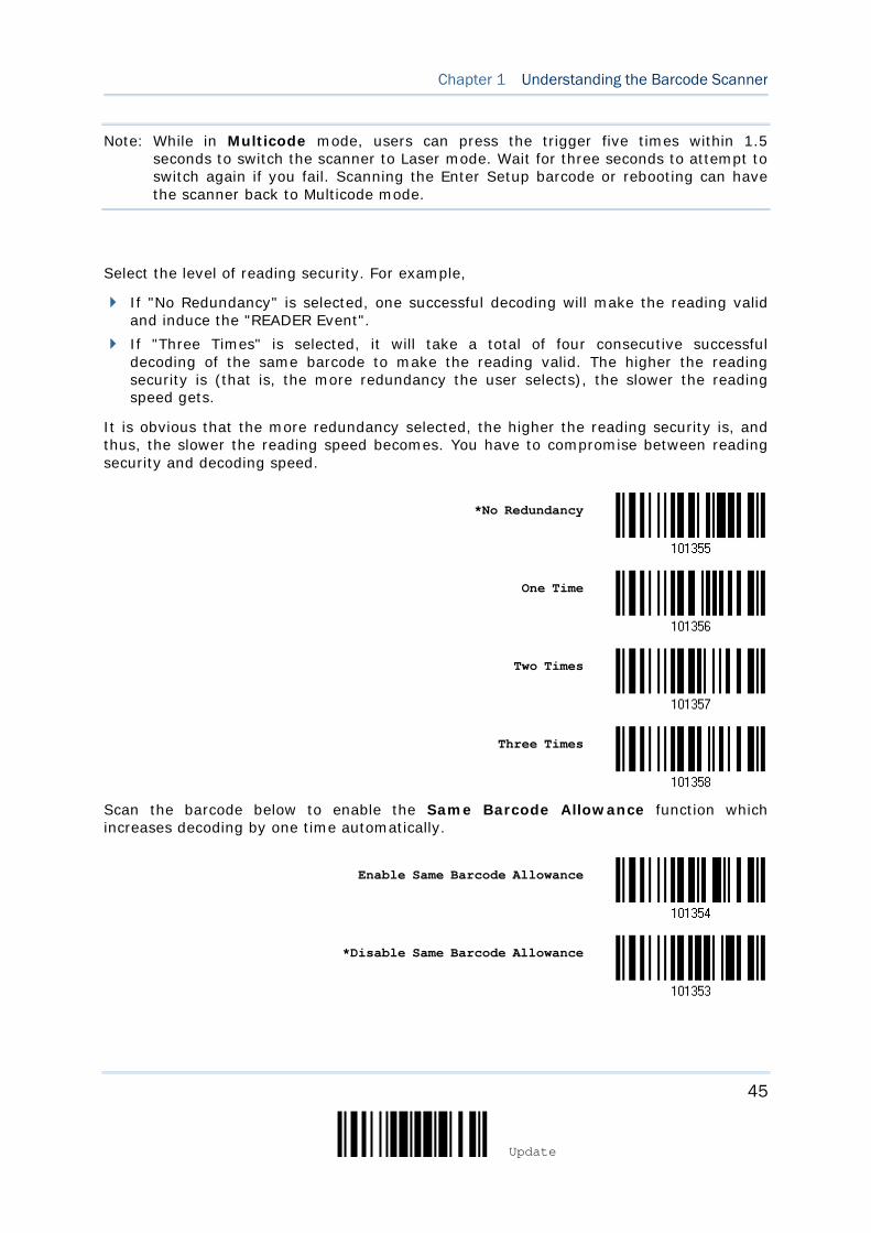
45
Update
Chapter 1 Understanding the Barcode Scanner
Note: While in Multicode mode, users can press the trigger five times within 1.5 seconds to switch the scanner to Laser mode. Wait for three seconds to attempt to switch again if you fail. Scanning the Enter Setup barcode or rebooting can have the scanner back to Multicode mode.
Select the level of reading security. For example,
If "No Redundancy" is selected, one successful decoding will make the reading valid and induce the "READER Event".
If "Three Times" is selected, it will take a total of four consecutive successful decoding of the same barcode to make the reading valid. The higher the reading security is (that is, the more redundancy the user selects), the slower the reading speed gets.
It is obvious that the more redundancy selected, the higher the reading security is, and thus, the slower the reading speed becomes. You have to compromise between reading security and decoding speed.
*No Redundancy
One Time
Two Times
Three Times
Scan the barcode below to enable the Same Barcode Allowance function which increases decoding by one time automatically.
Enable Same Barcode Allowance
*Disable Same Barcode Allowance
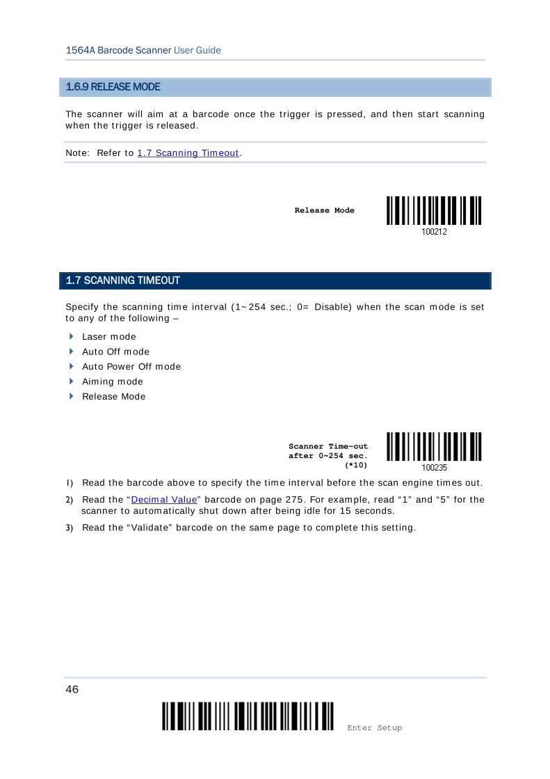
46
Enter Setup
1564A Barcode Scanner User Guide
1.6.9 RELEASE MODE
The scanner will aim at a barcode once the trigger is pressed, and then start scanning when the trigger is released.
Note: Refer to 1.7 Scanning Timeout.
Release Mode
1.7 SCANNING TIMEOUT
Specify the scanning time interval (1~254 sec.; 0= Disable) when the scan mode is set to any of the following –
Laser mode Auto Off mode Auto Power Off mode Aiming mode Release Mode
Scanner Time-out after 0~254 sec.
(*10)
1) Read the barcode above to specify the time interval before the scan engine times out.
2) Read the “Decimal Value” barcode on page 275. For example, read “1” and “5” for the scanner to automatically shut down after being idle for 15 seconds.
3) Read the “Validate” barcode on the same page to complete this setting.
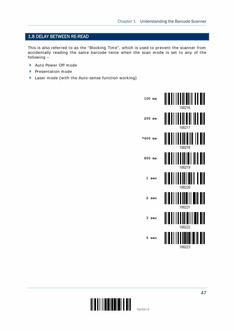
47
Update
Chapter 1 Understanding the Barcode Scanner
1.8 DELAY BETWEEN RE-READ
This is also referred to as the “Blocking Time”, which is used to prevent the scanner from accidentally reading the same barcode twice when the scan mode is set to any of the following –
Auto Power Off mode Presentation mode Laser mode (with the Auto-sense function working)
100 ms
200 ms
*400 ms
800 ms
1 sec
2 sec
3 sec
5 sec
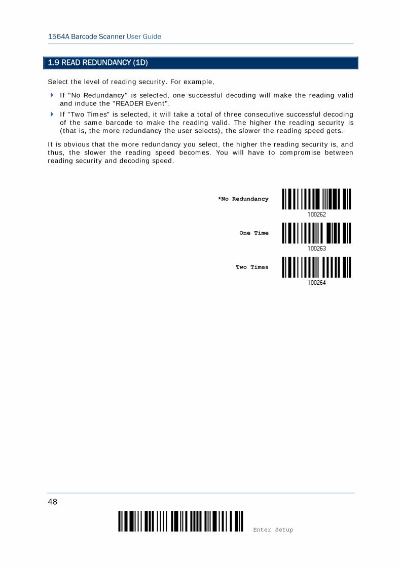
48
Enter Setup
1564A Barcode Scanner User Guide
1.9 READ REDUNDANCY (1D)
Select the level of reading security. For example,
If "No Redundancy" is selected, one successful decoding will make the reading valid and induce the "READER Event".
If "Two Times" is selected, it will take a total of three consecutive successful decoding of the same barcode to make the reading valid. The higher the reading security is (that is, the more redundancy the user selects), the slower the reading speed gets.
It is obvious that the more redundancy you select, the higher the reading security is, and thus, the slower the reading speed becomes. You will have to compromise between reading security and decoding speed.
*No Redundancy
One Time
Two Times
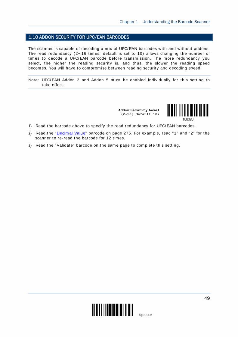
49
Update
Chapter 1 Understanding the Barcode Scanner
1.10 ADDON SECURITY FOR UPC/EAN BARCODES
The scanner is capable of decoding a mix of UPC/EAN barcodes with and without addons. The read redundancy (2~16 times; default is set to 10) allows changing the number of times to decode a UPC/EAN barcode before transmission. The more redundancy you select, the higher the reading security is, and thus, the slower the reading speed becomes. You will have to compromise between reading security and decoding speed.
Note: UPC/EAN Addon 2 and Addon 5 must be enabled individually for this setting to take effect.
Addon Security Level (2~16; default:10)
1) Read the barcode above to specify the read redundancy for UPC/EAN barcodes.
2) Read the “Decimal Value” barcode on page 275. For example, read “1” and “2” for the scanner to re-read the barcode for 12 times.
3) Read the “Validate” barcode on the same page to complete this setting.
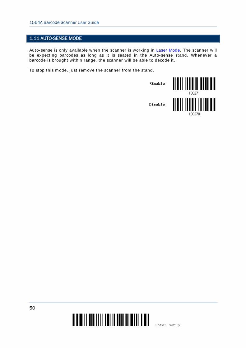
50
Enter Setup
1564A Barcode Scanner User Guide
1.11 AUTO-SENSE MODE
Auto-sense is only available when the scanner is working in Laser Mode. The scanner will be expecting barcodes as long as it is seated in the Auto-sense stand. Whenever a barcode is brought within range, the scanner will be able to decode it.
To stop this mode, just remove the scanner from the stand.
*Enable
Disable
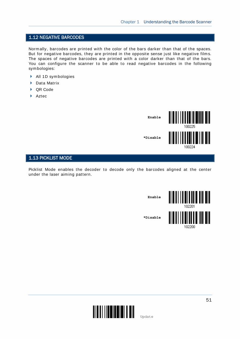
51
Update
Chapter 1 Understanding the Barcode Scanner
1.12 NEGATIVE BARCODES
Normally, barcodes are printed with the color of the bars darker than that of the spaces. But for negative barcodes, they are printed in the opposite sense just like negative films. The spaces of negative barcodes are printed with a color darker than that of the bars. You can configure the scanner to be able to read negative barcodes in the following symbologies:
All 1D symbologies Data Matrix QR Code Aztec
Enable
*Disable
1.13 PICKLIST MODE
Picklist Mode enables the decoder to decode only the barcodes aligned at the center under the laser aiming pattern.
Enable
*Disable
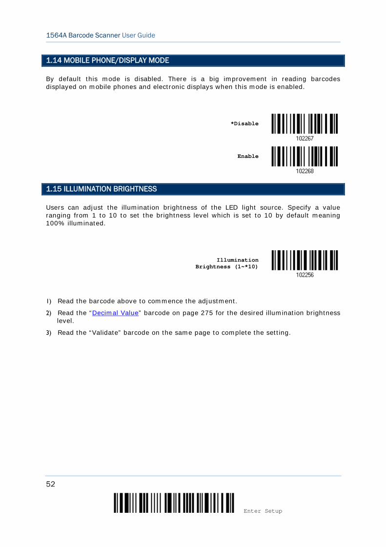
52
Enter Setup
1564A Barcode Scanner User Guide
1.14 MOBILE PHONE/DISPLAY MODE
By default this mode is disabled. There is a big improvement in reading barcodes displayed on mobile phones and electronic displays when this mode is enabled.
*Disable
Enable
1.15 ILLUMINATION BRIGHTNESS
Users can adjust the illumination brightness of the LED light source. Specify a value ranging from 1 to 10 to set the brightness level which is set to 10 by default meaning 100% illuminated.
Illumination
Brightness (1~*10)
1) Read the barcode above to commence the adjustment.
2) Read the “Decimal Value” barcode on page 275 for the desired illumination brightness level.
3) Read the “Validate” barcode on the same page to complete the setting.
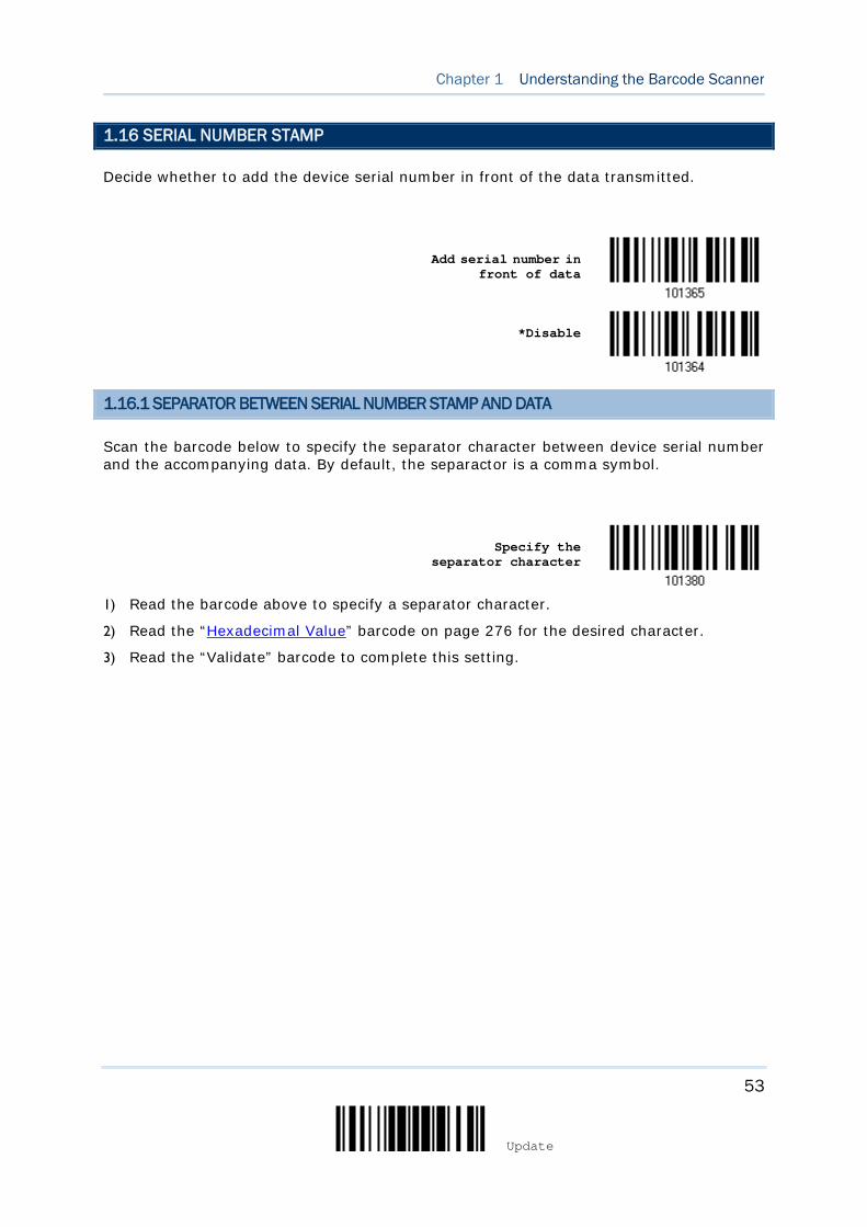
53
Update
Chapter 1 Understanding the Barcode Scanner
1.16 SERIAL NUMBER STAMP
Decide whether to add the device serial number in front of the data transmitted.
Add serial number in
front of data
*Disable
1.16.1 SEPARATOR BETWEEN SERIAL NUMBER STAMP AND DATA
Scan the barcode below to specify the separator character between device serial number and the accompanying data. By default, the separactor is a comma symbol.
Specify the
separator character
1) Read the barcode above to specify a separator character.
2) Read the “Hexadecimal Value” barcode on page 276 for the desired character.
3) Read the “Validate” barcode to complete this setting.
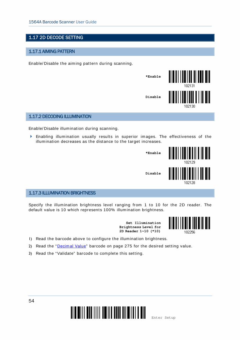
54
Enter Setup
1564A Barcode Scanner User Guide
1.17 2D DECODE SETTING
1.17.1 AIMING PATTERN
Enable/Disable the aiming pattern during scanning.
*Enable
Disable
1.17.2 DECODING ILLUMINATION
Enable/Disable illumination during scanning.
Enabling illumination usually results in superior images. The effectiveness of the illumination decreases as the distance to the target increases.
*Enable
Disable
1.17.3 ILLUMINATION BRIGHTNESS
Specify the illumination brightness level ranging from 1 to 10 for the 2D reader. The default value is 10 which represents 100% illumination brightness.
Set Illumination
Brightness Level for 2D Reader 1~10 (*10)
1) Read the barcode above to configure the illumination brightness.
2) Read the “Decimal Value” barcode on page 275 for the desired setting value.
3) Read the “Validate” barcode to complete this setting.
55
Update
In order to establish a proper connection between your computer and the scanner, we suggest that you follow these instructions –
1) Install the battery and hold down the trigger for about 2 seconds to turn on the scanner.
2) Have the scanner read the “Enter Setup” barcode to enter the configuration mode.
3) Have the scanner read the associated barcodes to activate the desired interface. See the following sections for output interfaces supported.
4) Have the scanner read the barcodes for related settings.
5) Have the scanner read the “Update” barcode to exit the configuration mode.
6) Turn on your computer or laptop and establish a WPAN connection with the scanner.
Refer to Chapter 3 – Setting up a WPAN Connection.
Note: By default, the output interface is set to “BT HID”.
IN THIS CHAPTER
2.1 BT HID ...................................................................... 56 2.2 BT SPP Slave .............................................................. 67 2.3 BT SPP Master ............................................................ 73 2.4 Keyboard Wedge via 3656 ........................................... 78 2.5 RS-232 via 3656 ......................................................... 89 2.6 USB HID via 3656 ....................................................... 94 2.7 USB Virtual COM via 3656 .......................................... 106
Chapter 2 SELECTING OUTPUT INTERFACE
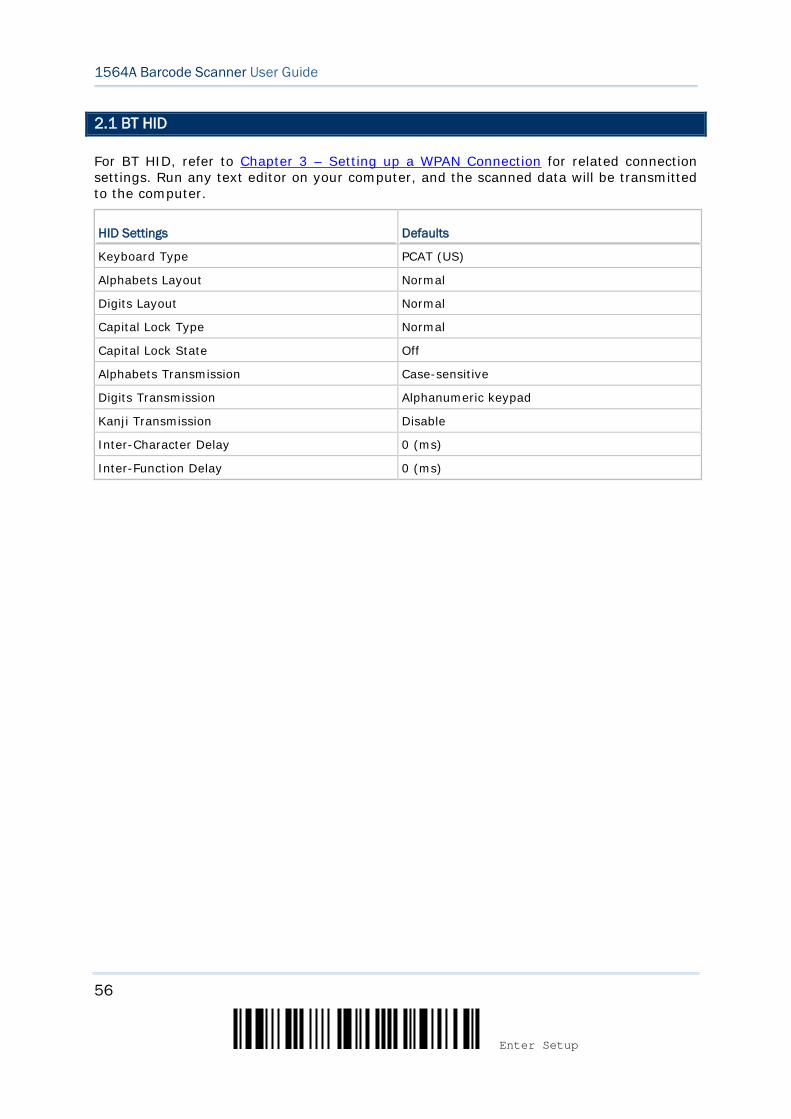
56
Enter Setup
1564A Barcode Scanner User Guide
2.1 BT HID
For BT HID, refer to Chapter 3 – Setting up a WPAN Connection for related connection settings. Run any text editor on your computer, and the scanned data will be transmitted to the computer.
HID Settings Defaults
Keyboard Type PCAT (US)
Alphabets Layout Normal
Digits Layout Normal
Capital Lock Type Normal
Capital Lock State Off
Alphabets Transmission Case-sensitive
Digits Transmission Alphanumeric keypad
Kanji Transmission Disable
Inter-Character Delay 0 (ms)
Inter-Function Delay 0 (ms)
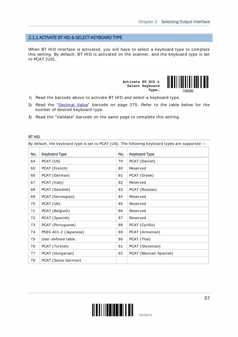
57
Update
Chapter 2 Selecting Output Interface
2.1.1 ACTIVATE BT HID & SELECT KEYBOARD TYPE
When BT HID interface is activated, you will have to select a keyboard type to complete this setting. By default, BT HID is activated on the scanner, and the keyboard type is set to PCAT (US).
Activate BT HID & Select Keyboard
Type…
1) Read the barcode above to activate BT HID and select a keyboard type.
2) Read the “Decimal Value” barcode on page 275. Refer to the table below for the number of desired keyboard type.
3) Read the “Validate” barcode on the same page to complete this setting.
BT HID
By default, the keyboard type is set to PCAT (US). The following keyboard types are supported —
No. Keyboard Type No. Keyboard Type
64 PCAT (US) 79 PCAT (Danish)
65 PCAT (French) 80 Reserved
66 PCAT (German) 81 PCAT (Greek)
67 PCAT (Italy) 82 Reserved
68 PCAT (Swedish) 83 PCAT (Russian)
69 PCAT (Norwegian) 84 Reserved
70 PCAT (UK) 85 Reserved
71 PCAT (Belgium) 86 Reserved
72 PCAT (Spanish) 87 Reserved
73 PCAT (Portuguese) 88 PCAT (Cyrillic)
74 PS55 A01-2 (Japanese) 89 PCAT (Armenian)
75 User-defined table 90 PCAT (Thai)
76 PCAT (Turkish) 91 PCAT (Slovenian)
77 PCAT (Hungarian) 92 PCAT (Mexican Spanish)
78 PCAT (Swiss German)
58
Enter Setup
1564A Barcode Scanner User Guide
2.1.2 RESET CONNECTION
For BT HID, you can only have the scanner connected to one computer at a time. If you want to connect the scanner to another host, you must have it read the “Reset Connection” barcode so that the current connection record will be cleared. Then, the scanner will restart itself automatically. Go through the whole process in 3.2.3 Connect to Dongle to establish a new connection.
Reset Connection
Note: The “Restore System Defaults” barcode will have the current connection record cleared as well.
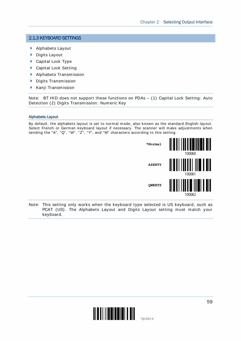
59
Update
Chapter 2 Selecting Output Interface
2.1.3 KEYBOARD SETTINGS
Alphabets Layout Digits Layout Capital Lock Type Capital Lock Setting Alphabets Transmission Digits Transmission Kanji Transmission
Note: BT HID does not support these functions on PDAs – (1) Capital Lock Setting: Auto Detection (2) Digits Transmission: Numeric Key
Alphabets Layout
By default, the alphabets layout is set to normal mode, also known as the standard English layout. Select French or German keyboard layout if necessary. The scanner will make adjustments when sending the "A", "Q", "W", "Z", "Y", and "M" characters according to this setting.
*Normal
AZERTY
QWERTZ
Note: This setting only works when the keyboard type selected is US keyboard, such as PCAT (US). The Alphabets Layout and Digits Layout setting must match your keyboard.
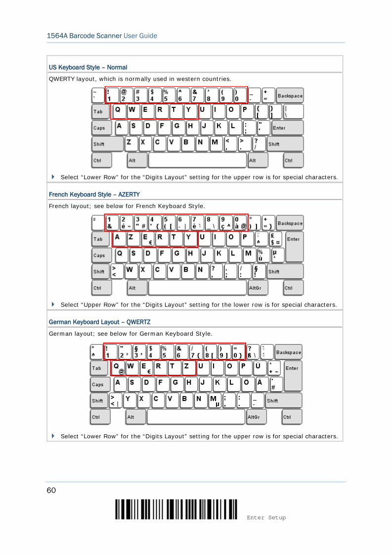
60
Enter Setup
1564A Barcode Scanner User Guide
US Keyboard Style – Normal
QWERTY layout, which is normally used in western countries.
Select “Lower Row” for the “Digits Layout” setting for the upper row is for special characters.
French Keyboard Style – AZERTY
French layout; see below for French Keyboard Style.
Select “Upper Row” for the “Digits Layout” setting for the lower row is for special characters.
German Keyboard Layout – QWERTZ
German layout; see below for German Keyboard Style.
Select “Lower Row” for the “Digits Layout” setting for the upper row is for special characters.

61
Update
Chapter 2 Selecting Output Interface
Digits Layout
Select a proper layout that matches the alphabets layout. The scanner will make adjustments according to this setting.
Options Description
Normal Depends on the [Shift] key or [Shift Lock] setting
Lower Row For QWERTY or QWERTZ keyboard
Upper Row For AZERTY keyboard
*Normal
Upper Row
Lower Row
Note: This setting is to be used with the Character Substitution setting when support to certain keyboard types (languages) is unavailable but required.
Capital Lock Type & Setting
In order to send the alphabets with correct case, the scanner needs to know the status of Caps Lock on the keyboard. Incorrect settings may result in reversed case of the alphabets being transmitted.
Cap Lock Type Description
Normal Normal type
Capital Lock When enabled, the keys of alphabetic characters will be interpreted as capital letters. However, this does not affect the number or punctuation keys.
Shift Lock When enabled, the keys of alphabetic characters will be interpreted as capital letters. In addition, this affects the number or punctuation keys.
*Normal
Shift Lock
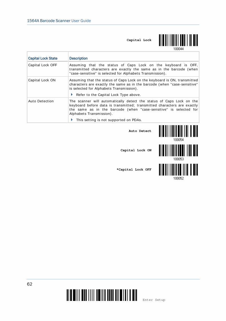
62
Enter Setup
1564A Barcode Scanner User Guide
Capital Lock
Capital Lock State Description
Capital Lock OFF Assuming that the status of Caps Lock on the keyboard is OFF, transmitted characters are exactly the same as in the barcode (when "case-sensitive" is selected for Alphabets Transmission).
Capital Lock ON Assuming that the status of Caps Lock on the keyboard is ON, transmitted characters are exactly the same as in the barcode (when "case-sensitive" is selected for Alphabets Transmission).
Refer to the Capital Lock Type above.
Auto Detection The scanner will automatically detect the status of Caps Lock on the keyboard before data is transmitted; transmitted characters are exactly the same as in the barcode (when "case-sensitive" is selected for Alphabets Transmission).
This setting is not supported on PDAs.
Auto Detect
Capital Lock ON
*Capital Lock OFF
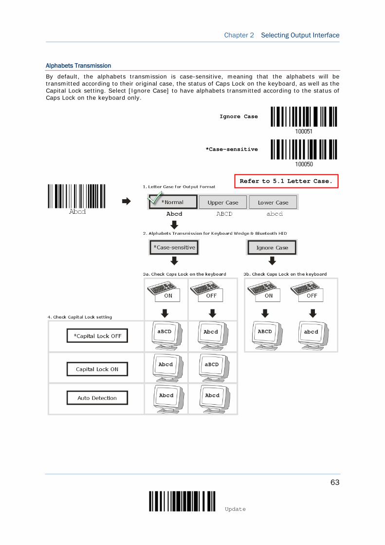
63
Update
Chapter 2 Selecting Output Interface
Alphabets Transmission
By default, the alphabets transmission is case-sensitive, meaning that the alphabets will be transmitted according to their original case, the status of Caps Lock on the keyboard, as well as the Capital Lock setting. Select [Ignore Case] to have alphabets transmitted according to the status of Caps Lock on the keyboard only.
Ignore Case
*Case-sensitive
Refer to 5.1 Letter Case.
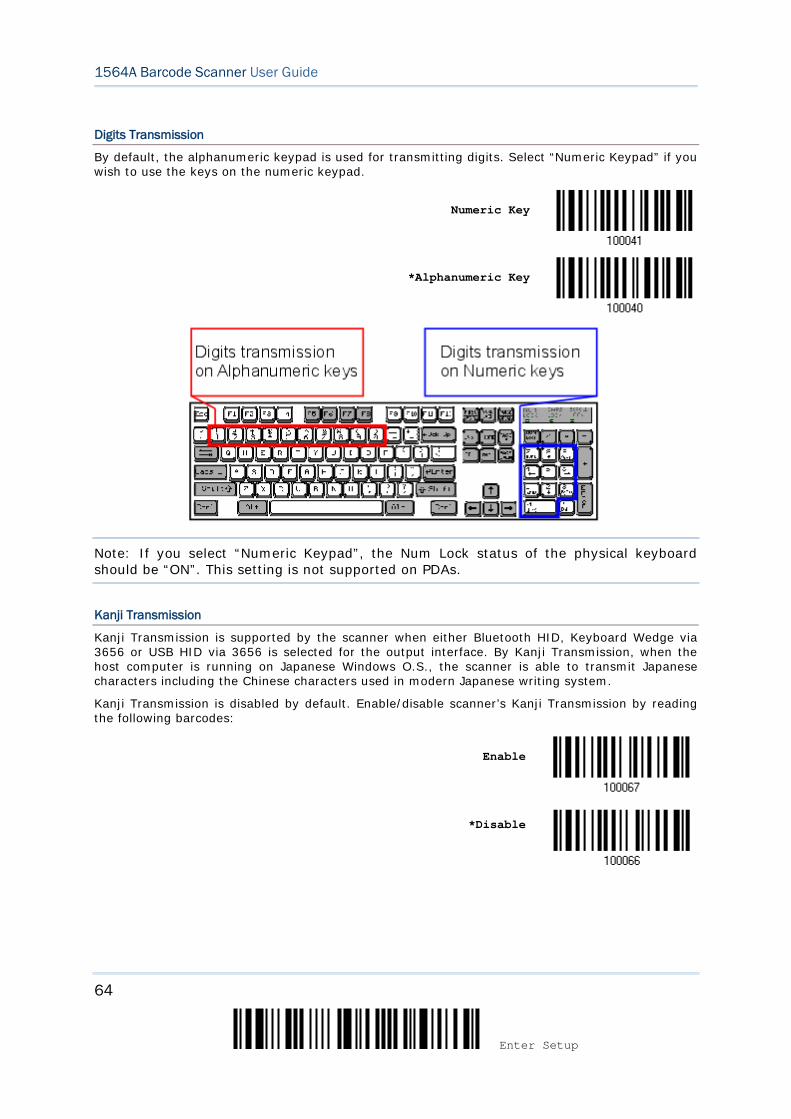
64
Enter Setup
1564A Barcode Scanner User Guide
Digits Transmission
By default, the alphanumeric keypad is used for transmitting digits. Select “Numeric Keypad” if you wish to use the keys on the numeric keypad.
Numeric Key
*Alphanumeric Key
Note: If you select “Numeric Keypad”, the Num Lock status of the physical keyboard should be “ON”. This setting is not supported on PDAs.
Kanji Transmission
Kanji Transmission is supported by the scanner when either Bluetooth HID, Keyboard Wedge via 3656 or USB HID via 3656 is selected for the output interface. By Kanji Transmission, when the host computer is running on Japanese Windows O.S., the scanner is able to transmit Japanese characters including the Chinese characters used in modern Japanese writing system.
Kanji Transmission is disabled by default. Enable/disable scanner’s Kanji Transmission by reading the following barcodes:
Enable
*Disable
65
Update
Chapter 2 Selecting Output Interface
2.1.4 INTER-CHARACTER DELAY
By default, the inter-character delay is set to zero. Specify a value, ranging from 0 to 254 in units of millisecond, to match the computer response time of the keyboard interface. Such delay time is inserted between every character being transmitted. The longer the delay time is, the slower the transmission speed will be.
Inter-Character Delay… (*0~254)
1) Read the barcode above to specify the inter-character delay.
2) Read the “Decimal Value” barcode on page 275 for the desired inter-character delay (millisecond).
3) Read the “Validate” barcode on the same page to complete this setting.
2.1.5 INTER-FUNCTION DELAY
By default, the inter-function delay is set to zero. Specify a value, ranging from 0 to 254 in units of millisecond, to match the computer response time of the keyboard interface. Such delay time is inserted between every function code (0x01 ~ 0x1F) being transmitted. The longer the delay time is, the slower the transmission speed will be.
Inter-Function
Delay… (*0~254)
1) Read the barcode above to specify the inter-function delay.
2) Read the “Decimal Value” barcode on page 275 for the desired inter-function delay (millisecond).
3) Read the “Validate” barcode on the same page to complete this setting.
66
Enter Setup
1564A Barcode Scanner User Guide
2.1.6 HID CHARACTER TRANSMIT MODE
By default, HID interface sends data to the host character by character. You may have the scanner read the “Batch Processing” barcode to process data in batch.
Batch Processing
*By Character
Note: “By Character” transmit mode is required when working with iPhone or iPad. It’s recommended that the Auto-Correction function on your iOS keyboard should be turned off.
2.1.7 SPECIAL KEYBOARD FEATURE
Users can set the special keyboard feature to Bypass, Apply, or Bypass with Control Character Output for Windows.
By default, this interface employ the “Bypass” special keyboard defined in Keyboard Wedge Table for users may want to get rid of these special codes within the barcodes to avoid data error.
Or you can enable the “Bypass with Control Character Output for Windows” function which can output control characters ranging from 0x01 to 0x1F on the Windows platform. For instance, [Alt]+[029] (GS, group separator) is output after the scanner reads the 0x1D character.
Apply
*Bypass
Bypass with Control Character Output
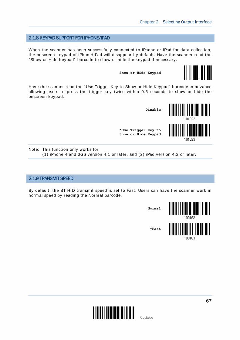
67
Update
Chapter 2 Selecting Output Interface
2.1.8 KEYPAD SUPPORT FOR IPHONE/IPAD
When the scanner has been successfully connected to iPhone or iPad for data collection, the onscreen keypad of iPhone/iPad will disappear by default. Have the scanner read the “Show or Hide Keypad” barcode to show or hide the keypad if necessary.
Show or Hide Keypad
Have the scanner read the “Use Trigger Key to Show or Hide Keypad” barcode in advance allowing users to press the trigger key twice within 0.5 seconds to show or hide the onscreen keypad.
Disable
*Use Trigger Key to Show or Hide Keypad
Note: This function only works for (1) iPhone 4 and 3GS version 4.1 or later, and (2) iPad version 4.2 or later.
2.1.9 TRANSMIT SPEED
By default, the BT HID transmit speed is set to Fast. Users can have the scanner work in normal speed by reading the Normal barcode.
Normal
*Fast
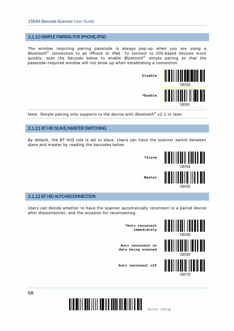
68
Enter Setup
1564A Barcode Scanner User Guide
2.1.10 SIMPLE PAIRING FOR IPHONE/IPAD
The window requiring pairing passcode is always pop-up when you are using a Bluetooth® connection to an iPhone or iPad. To connect to iOS-based devices more quickly, scan the barcode below to enable Bluetooth® simple pairing so that the passcode-required window will not show up when establishing a connection.
Disable
*Enable
Note: Simple pairing only supports to the device with Bluetooth® v2.1 or later.
2.1.11 BT HID SLAVE/MASTER SWITCHING
By default, the BT HID role is set to slave. Users can have the scanner switch between slave and master by reading the barcodes below.
*Slave
Master
2.1.12 BT HID AUTO-RECONNECTION
Users can decide whether to have the scanner automatically reconnect to a paired device after disconnection, and the occasion for reconnecting.
*Auto reconnect
immediately
Auto reconnect on data being scanned
Auto reconnect off
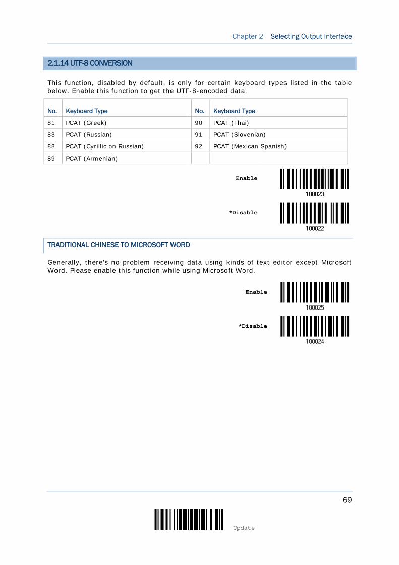
69
Update
Chapter 2 Selecting Output Interface
2.1.14 UTF-8 CONVERSION
This function, disabled by default, is only for certain keyboard types listed in the table below. Enable this function to get the UTF-8-encoded data.
No. Keyboard Type No. Keyboard Type
81 PCAT (Greek) 90 PCAT (Thai)
83 PCAT (Russian) 91 PCAT (Slovenian)
88 PCAT (Cyrillic on Russian) 92 PCAT (Mexican Spanish)
89 PCAT (Armenian)
Enable
*Disable
TRADITIONAL CHINESE TO MICROSOFT WORD
Generally, there’s no problem receiving data using kinds of text editor except Microsoft Word. Please enable this function while using Microsoft Word.
Enable
*Disable
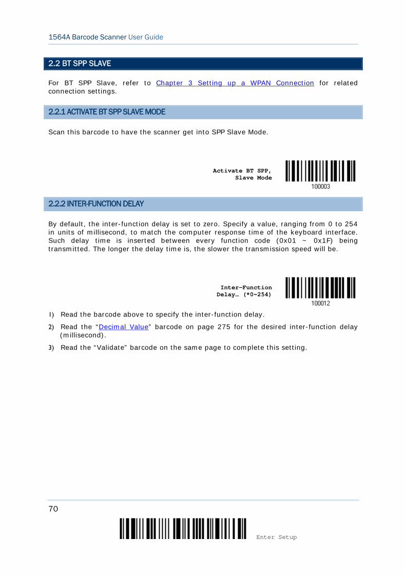
70
Enter Setup
1564A Barcode Scanner User Guide
2.2 BT SPP SLAVE
For BT SPP Slave, refer to Chapter 3 Setting up a WPAN Connection for related connection settings.
2.2.1 ACTIVATE BT SPP SLAVE MODE
Scan this barcode to have the scanner get into SPP Slave Mode.
Activate BT SPP,
Slave Mode
2.2.2 INTER-FUNCTION DELAY
By default, the inter-function delay is set to zero. Specify a value, ranging from 0 to 254 in units of millisecond, to match the computer response time of the keyboard interface. Such delay time is inserted between every function code (0x01 ~ 0x1F) being transmitted. The longer the delay time is, the slower the transmission speed will be.
Inter-Function
Delay… (*0~254)
1) Read the barcode above to specify the inter-function delay.
2) Read the “Decimal Value” barcode on page 275 for the desired inter-function delay (millisecond).
3) Read the “Validate” barcode on the same page to complete this setting.
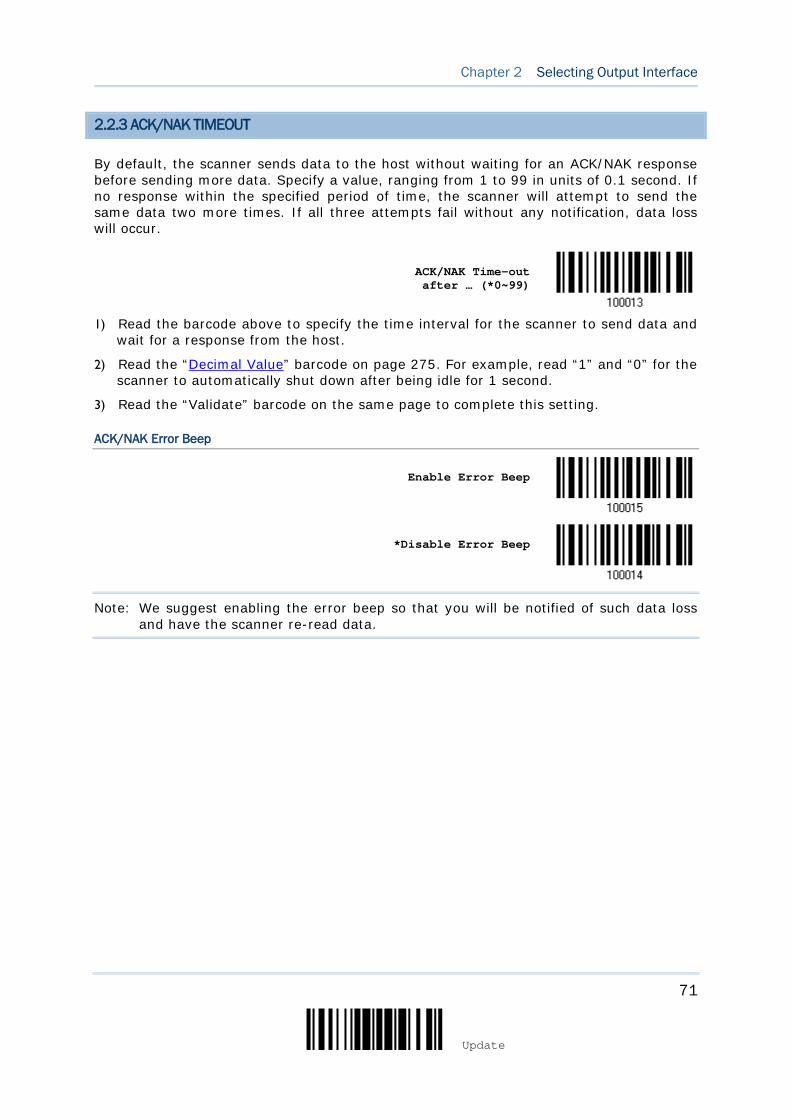
71
Update
Chapter 2 Selecting Output Interface
2.2.3 ACK/NAK TIMEOUT
By default, the scanner sends data to the host without waiting for an ACK/NAK response before sending more data. Specify a value, ranging from 1 to 99 in units of 0.1 second. If no response within the specified period of time, the scanner will attempt to send the same data two more times. If all three attempts fail without any notification, data loss will occur.
ACK/NAK Time-out after … (*0~99)
1) Read the barcode above to specify the time interval for the scanner to send data and
wait for a response from the host.
2) Read the “Decimal Value” barcode on page 275. For example, read “1” and “0” for the scanner to automatically shut down after being idle for 1 second.
3) Read the “Validate” barcode on the same page to complete this setting.
ACK/NAK Error Beep
Enable Error Beep
*Disable Error Beep
Note: We suggest enabling the error beep so that you will be notified of such data loss and have the scanner re-read data.
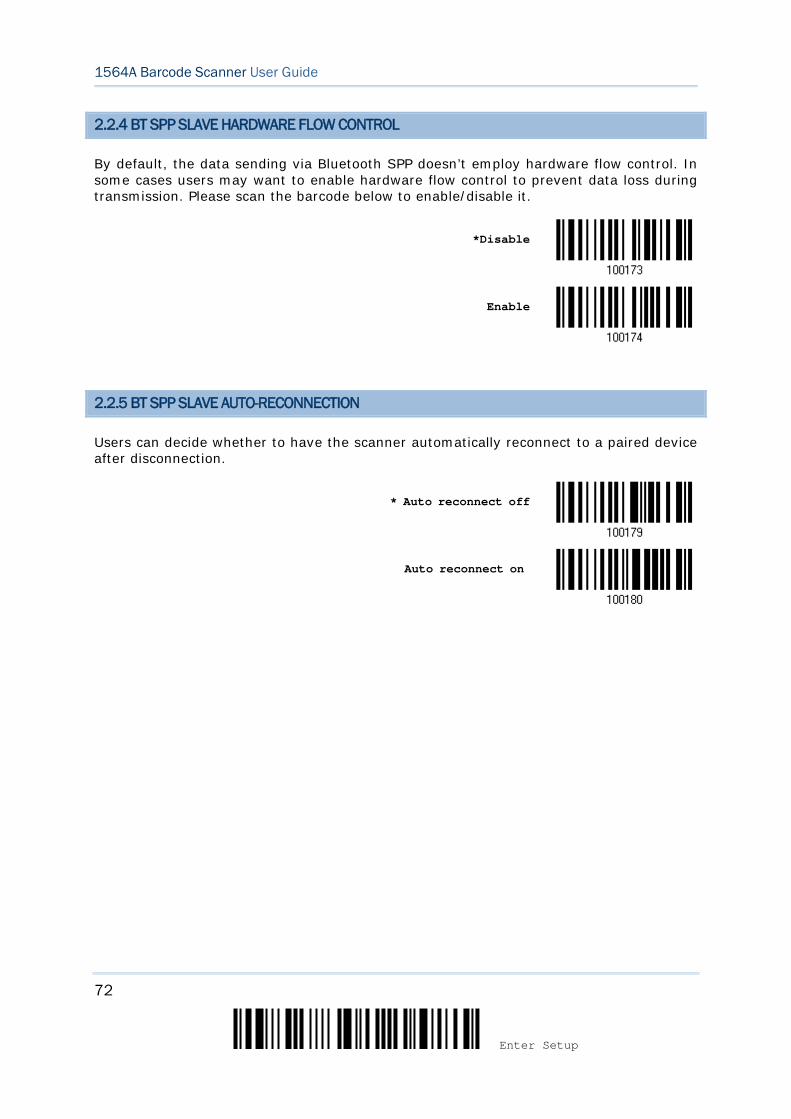
72
Enter Setup
1564A Barcode Scanner User Guide
2.2.4 BT SPP SLAVE HARDWARE FLOW CONTROL
By default, the data sending via Bluetooth SPP doesn’t employ hardware flow control. In some cases users may want to enable hardware flow control to prevent data loss during transmission. Please scan the barcode below to enable/disable it.
*Disable
Enable
2.2.5 BT SPP SLAVE AUTO-RECONNECTION
Users can decide whether to have the scanner automatically reconnect to a paired device after disconnection.
* Auto reconnect off
Auto reconnect on
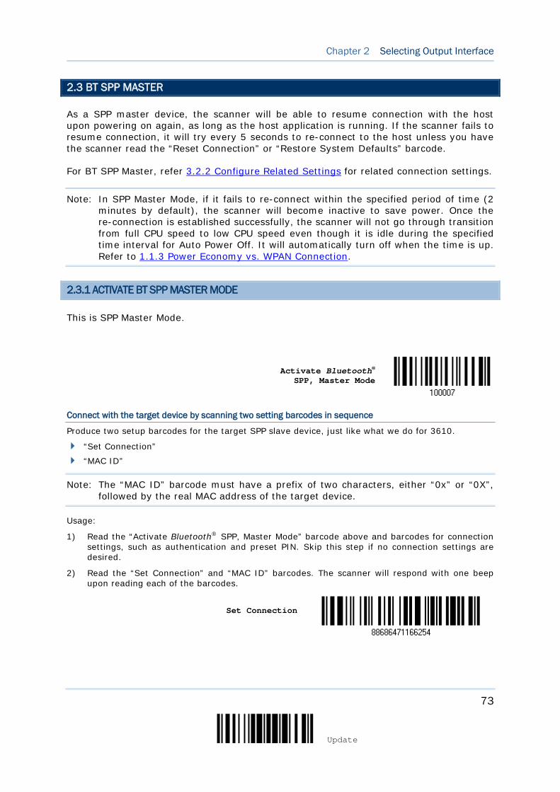
73
Update
Chapter 2 Selecting Output Interface
2.3 BT SPP MASTER
As a SPP master device, the scanner will be able to resume connection with the host upon powering on again, as long as the host application is running. If the scanner fails to resume connection, it will try every 5 seconds to re-connect to the host unless you have the scanner read the “Reset Connection” or “Restore System Defaults” barcode.
For BT SPP Master, refer 3.2.2 Configure Related Settings for related connection settings.
Note: In SPP Master Mode, if it fails to re-connect within the specified period of time (2 minutes by default), the scanner will become inactive to save power. Once the re-connection is established successfully, the scanner will not go through transition from full CPU speed to low CPU speed even though it is idle during the specified time interval for Auto Power Off. It will automatically turn off when the time is up. Refer to 1.1.3 Power Economy vs. WPAN Connection.
2.3.1 ACTIVATE BT SPP MASTER MODE
This is SPP Master Mode.
Activate Bluetooth®
SPP, Master Mode
Connect with the target device by scanning two setting barcodes in sequence
Produce two setup barcodes for the target SPP slave device, just like what we do for 3610.
“Set Connection”
“MAC ID”
Note: The “MAC ID” barcode must have a prefix of two characters, either “0x” or “0X”, followed by the real MAC address of the target device.
Usage:
1) Read the “Activate Bluetooth® SPP, Master Mode” barcode above and barcodes for connection settings, such as authentication and preset PIN. Skip this step if no connection settings are desired.
2) Read the “Set Connection” and “MAC ID” barcodes. The scanner will respond with one beep upon reading each of the barcodes.
Set Connection
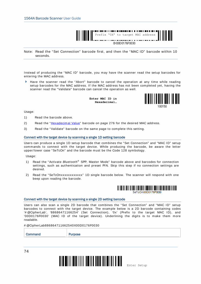
74
Enter Setup
1564A Barcode Scanner User Guide
Note: Read the “Set Connection” barcode first, and then the “MAC ID” barcode within 10 seconds.
Instead of producing the “MAC ID” barcode, you may have the scanner read the setup barcodes for entering the MAC address.
Have the scanner read the “Abort” barcode to cancel the operation at any time while reading setup barcodes for the MAC address. If the MAC address has not been completed yet, having the scanner read the “Validate” barcode can cancel the operation as well.
Enter MAC ID in
Hexadecimal…
Usage:
1) Read the barcode above.
2) Read the “Hexadecimal Value” barcode on page 276 for the desired MAC address.
3) Read the “Validate” barcode on the same page to complete this setting.
Connect with the target device by scanning a single 1D setting barcode
Users can produce a single 1D setup barcode that combines the “Set Connection” and “MAC ID” setup commands to connect with the target device. While producing the barcode, be aware the letter upper/lower case “SeTcOn” and the barcode must be the Code 128 symbology.
Usage:
1) Read the “Activate Bluetooth® SPP, Master Mode” barcode above and barcodes for connection settings, such as authentication and preset PIN. Skip this step if no connection settings are desired.
2) Read the “SeTcOnxxxxxxxxxxxx” 1D single barcode below. The scanner will respond with one beep upon reading the barcode.
Connect with the target device by scanning a single 2D setting barcode
Users can also scan a single 2D barcode that combines the “Set Connection” and “MAC ID” setup barcodes to connect with the target device. The example below is a 2D barcode containing codes ‘#@CipherLab’, ‘88686471166254’ (Set Connection), ‘0x’ (Prefix to the target MAC ID), and ‘00D0176F0030’ (MAC ID of the target device). Underlining the digits is to make them more readable.
#@CipherLab886864711662540X00D0176F0030
Command Purpose
Prefix “0X” to target MAC address
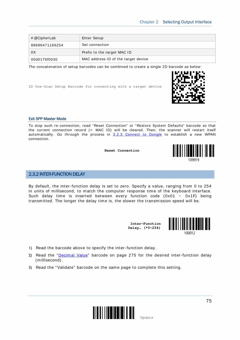
75
Update
Chapter 2 Selecting Output Interface
#@CipherLab Enter Setup
88686471166254 Set connection
0X Prefix to the target MAC ID
00d0176f0030 MAC address ID of the target device
The concatenation of setup barcodes can be combined to create a single 2D barcode as below:
2D One-Scan Setup Barcode for connecting with a target device
Exit SPP Master Mode
To stop such re-connection, read “Reset Connection” or “Restore System Defaults” barcode so that the current connection record (= MAC ID) will be cleared. Then, the scanner will restart itself automatically. Go through the process in 3.2.3 Connect to Dongle to establish a new WPAN connection.
Reset Connection
2.3.2 INTER-FUNCTION DELAY
By default, the inter-function delay is set to zero. Specify a value, ranging from 0 to 254 in units of millisecond, to match the computer response time of the keyboard interface. Such delay time is inserted between every function code (0x01 ~ 0x1F) being transmitted. The longer the delay time is, the slower the transmission speed will be.
Inter-Function
Delay… (*0~254)
1) Read the barcode above to specify the inter-function delay.
2) Read the “Decimal Value” barcode on page 275 for the desired inter-function delay (millisecond).
3) Read the “Validate” barcode on the same page to complete this setting.
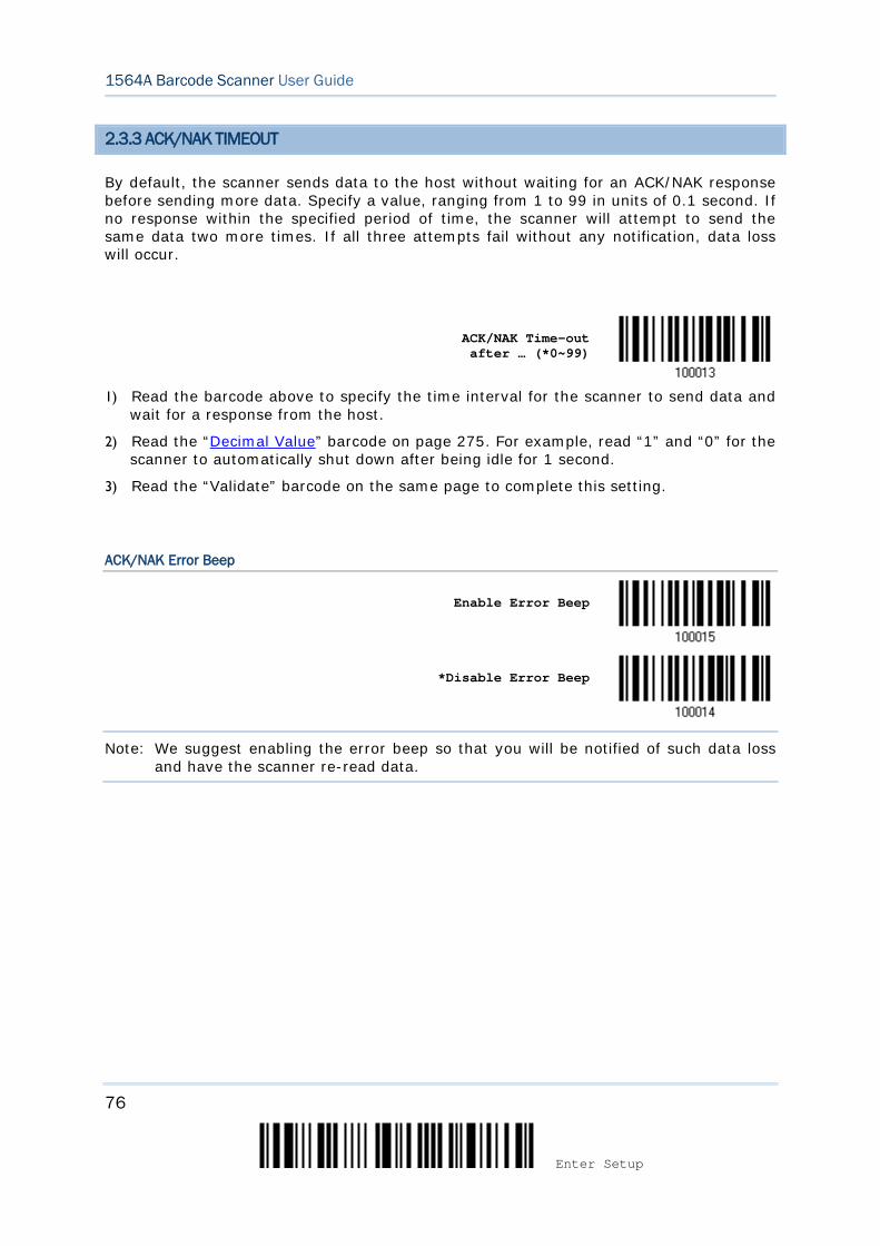
76
Enter Setup
1564A Barcode Scanner User Guide
2.3.3 ACK/NAK TIMEOUT
By default, the scanner sends data to the host without waiting for an ACK/NAK response before sending more data. Specify a value, ranging from 1 to 99 in units of 0.1 second. If no response within the specified period of time, the scanner will attempt to send the same data two more times. If all three attempts fail without any notification, data loss will occur.
ACK/NAK Time-out after … (*0~99)
1) Read the barcode above to specify the time interval for the scanner to send data and
wait for a response from the host.
2) Read the “Decimal Value” barcode on page 275. For example, read “1” and “0” for the scanner to automatically shut down after being idle for 1 second.
3) Read the “Validate” barcode on the same page to complete this setting.
ACK/NAK Error Beep
Enable Error Beep
*Disable Error Beep
Note: We suggest enabling the error beep so that you will be notified of such data loss and have the scanner re-read data.
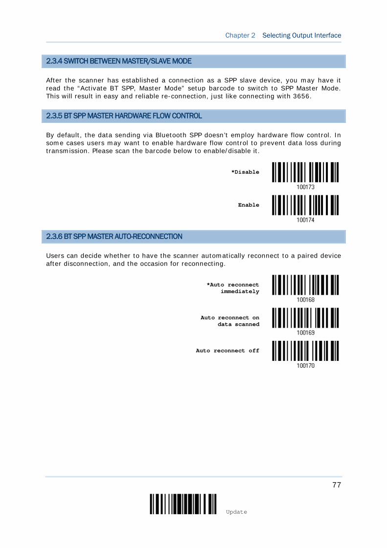
77
Update
Chapter 2 Selecting Output Interface
2.3.4 SWITCH BETWEEN MASTER/SLAVE MODE
After the scanner has established a connection as a SPP slave device, you may have it read the “Activate BT SPP, Master Mode” setup barcode to switch to SPP Master Mode. This will result in easy and reliable re-connection, just like connecting with 3656.
2.3.5 BT SPP MASTER HARDWARE FLOW CONTROL
By default, the data sending via Bluetooth SPP doesn’t employ hardware flow control. In some cases users may want to enable hardware flow control to prevent data loss during transmission. Please scan the barcode below to enable/disable it.
*Disable
Enable
2.3.6 BT SPP MASTER AUTO-RECONNECTION
Users can decide whether to have the scanner automatically reconnect to a paired device after disconnection, and the occasion for reconnecting.
*Auto reconnect
immediately
Auto reconnect on data scanned
Auto reconnect off
78
Enter Setup
1564A Barcode Scanner User Guide
2.4 KEYBOARD WEDGE VIA 3656
The Y cable allows you to connect the scanner via 3656 to the keyboard input port of PC and you may join the keyboard as well. The scanned data will be transmitted to the host keyboard port as if it is manually entered via the keyboard. For example, run a text editor on your computer to receive the data.
Keyboard Wedge Settings Defaults
Keyboard Type PCAT (US)
Alphabets Layout Normal
Digits Layout Normal
Capital Lock Type Normal
Capital Lock State Off
Alphabets Transmission Case-sensitive
Digits Transmission Alphanumeric keypad
Kanji Transmission Disable
Alternate Composing No
Laptop Support Disable
Inter-Character Delay 0 (ms)
Inter-Function Delay 0 (ms)
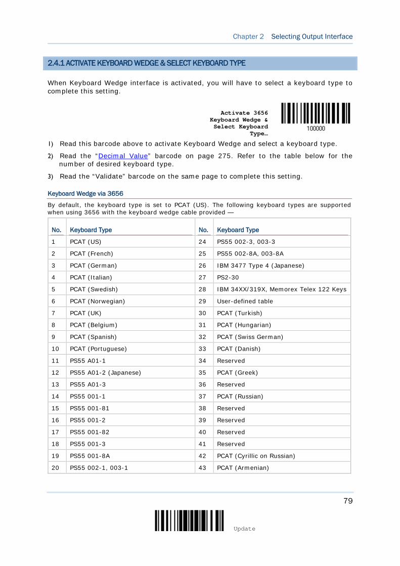
79
Update
Chapter 2 Selecting Output Interface
2.4.1 ACTIVATE KEYBOARD WEDGE & SELECT KEYBOARD TYPE
When Keyboard Wedge interface is activated, you will have to select a keyboard type to complete this setting.
Activate 3656
Keyboard Wedge & Select Keyboard
Type…
1) Read this barcode above to activate Keyboard Wedge and select a keyboard type.
2) Read the “Decimal Value” barcode on page 275. Refer to the table below for the number of desired keyboard type.
3) Read the “Validate” barcode on the same page to complete this setting.
Keyboard Wedge via 3656
By default, the keyboard type is set to PCAT (US). The following keyboard types are supported when using 3656 with the keyboard wedge cable provided —
No. Keyboard Type No. Keyboard Type
1 PCAT (US) 24 PS55 002-3, 003-3
2 PCAT (French) 25 PS55 002-8A, 003-8A
3 PCAT (German) 26 IBM 3477 Type 4 (Japanese)
4 PCAT (Italian) 27 PS2-30
5 PCAT (Swedish) 28 IBM 34XX/319X, Memorex Telex 122 Keys
6 PCAT (Norwegian) 29 User-defined table
7 PCAT (UK) 30 PCAT (Turkish)
8 PCAT (Belgium) 31 PCAT (Hungarian)
9 PCAT (Spanish) 32 PCAT (Swiss German)
10 PCAT (Portuguese) 33 PCAT (Danish)
11 PS55 A01-1 34 Reserved
12 PS55 A01-2 (Japanese) 35 PCAT (Greek)
13 PS55 A01-3 36 Reserved
14 PS55 001-1 37 PCAT (Russian)
15 PS55 001-81 38 Reserved
16 PS55 001-2 39 Reserved
17 PS55 001-82 40 Reserved
18 PS55 001-3 41 Reserved
19 PS55 001-8A 42 PCAT (Cyrillic on Russian)
20 PS55 002-1, 003-1 43 PCAT (Armenian)
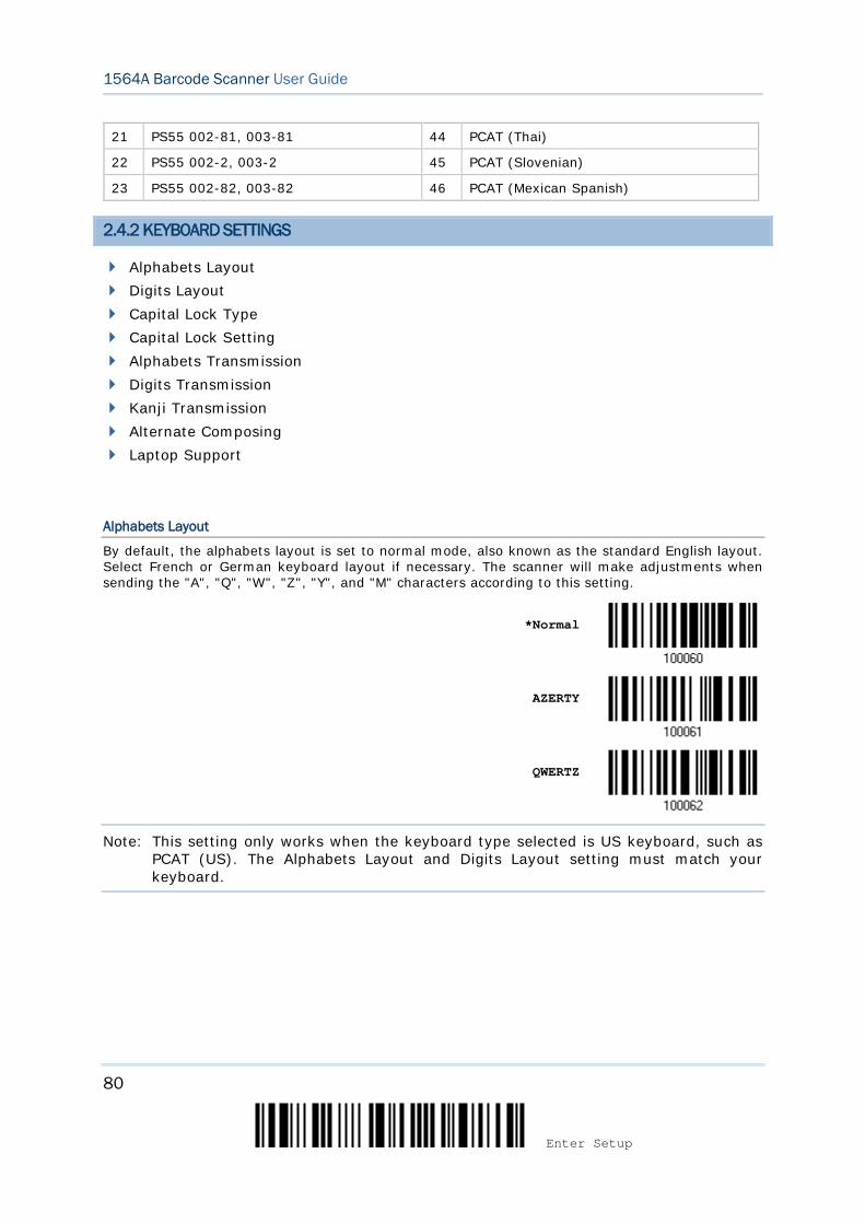
80
Enter Setup
1564A Barcode Scanner User Guide
21 PS55 002-81, 003-81 44 PCAT (Thai)
22 PS55 002-2, 003-2 45 PCAT (Slovenian)
23 PS55 002-82, 003-82 46 PCAT (Mexican Spanish)
2.4.2 KEYBOARD SETTINGS
Alphabets Layout Digits Layout Capital Lock Type Capital Lock Setting Alphabets Transmission Digits Transmission Kanji Transmission Alternate Composing Laptop Support
Alphabets Layout
By default, the alphabets layout is set to normal mode, also known as the standard English layout. Select French or German keyboard layout if necessary. The scanner will make adjustments when sending the "A", "Q", "W", "Z", "Y", and "M" characters according to this setting.
*Normal
AZERTY
QWERTZ
Note: This setting only works when the keyboard type selected is US keyboard, such as PCAT (US). The Alphabets Layout and Digits Layout setting must match your keyboard.
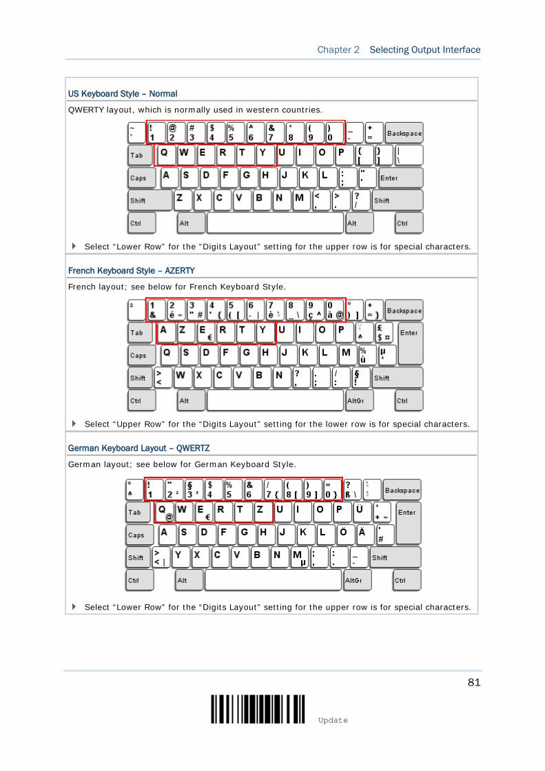
81
Update
Chapter 2 Selecting Output Interface
US Keyboard Style – Normal
QWERTY layout, which is normally used in western countries.
Select “Lower Row” for the “Digits Layout” setting for the upper row is for special characters.
French Keyboard Style – AZERTY
French layout; see below for French Keyboard Style.
Select “Upper Row” for the “Digits Layout” setting for the lower row is for special characters.
German Keyboard Layout – QWERTZ
German layout; see below for German Keyboard Style.
Select “Lower Row” for the “Digits Layout” setting for the upper row is for special characters.
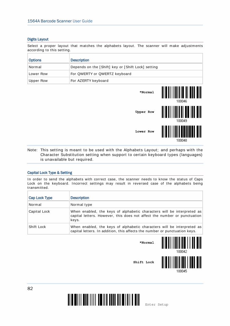
82
Enter Setup
1564A Barcode Scanner User Guide
Digits Layout
Select a proper layout that matches the alphabets layout. The scanner will make adjustments according to this setting.
Options Description
Normal Depends on the [Shift] key or [Shift Lock] setting
Lower Row For QWERTY or QWERTZ keyboard
Upper Row For AZERTY keyboard
*Normal
Upper Row
Lower Row
Note: This setting is meant to be used with the Alphabets Layout; and perhaps with the Character Substitution setting when support to certain keyboard types (languages) is unavailable but required.
Capital Lock Type & Setting
In order to send the alphabets with correct case, the scanner needs to know the status of Caps Lock on the keyboard. Incorrect settings may result in reversed case of the alphabets being transmitted.
Cap Lock Type Description
Normal Normal type
Capital Lock When enabled, the keys of alphabetic characters will be interpreted as capital letters. However, this does not affect the number or punctuation keys.
Shift Lock When enabled, the keys of alphabetic characters will be interpreted as capital letters. In addition, this affects the number or punctuation keys.
*Normal
Shift Lock
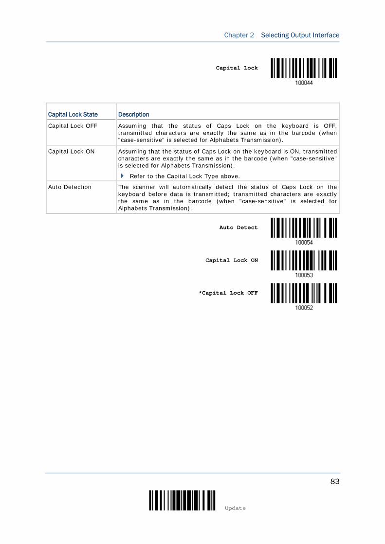
83
Update
Chapter 2 Selecting Output Interface
Capital Lock
Capital Lock State Description
Capital Lock OFF Assuming that the status of Caps Lock on the keyboard is OFF, transmitted characters are exactly the same as in the barcode (when "case-sensitive" is selected for Alphabets Transmission).
Capital Lock ON Assuming that the status of Caps Lock on the keyboard is ON, transmitted characters are exactly the same as in the barcode (when "case-sensitive" is selected for Alphabets Transmission).
Refer to the Capital Lock Type above.
Auto Detection The scanner will automatically detect the status of Caps Lock on the keyboard before data is transmitted; transmitted characters are exactly the same as in the barcode (when "case-sensitive" is selected for Alphabets Transmission).
Auto Detect
Capital Lock ON
*Capital Lock OFF

84
Enter Setup
1564A Barcode Scanner User Guide
Alphabets Transmission
By default, the alphabets transmission is case-sensitive, meaning that the alphabets will be transmitted according to their original case, the status of Caps Lock on the keyboard, as well as the Capital Lock setting. Select [Ignore Case] to have alphabets transmitted according to the status of Caps Lock on the keyboard only.
Ignore Case
*Case-sensitive
Refer to 5.1 Letter Case.

85
Update
Chapter 2 Selecting Output Interface
Digits Transmission
By default, the alphanumeric keypad is used for transmitting digits. Select “Numeric Keypad” if you wish to use the keys on the numeric keypad.
Numeric Key
*Alphanumeric Key
Note: If you select “Numeric Keypad”, the Num Lock status of the physical keyboard should be “ON”.
Kanji Transmission
Kanji Transmission is supported by the scanner when either Bluetooth HID, Keyboard Wedge via 3656 or USB HID via 3656 is selected for the output interface. By Kanji Transmission, when the host computer is running on Japanese Windows O.S., the scanner is able to transmit Japanese characters including the Chinese characters used in modern Japanese writing system.
Kanji Transmission is disabled by default. Enable/disable scanner’s Kanji Transmission by reading the following barcodes:
Enable
*Disable
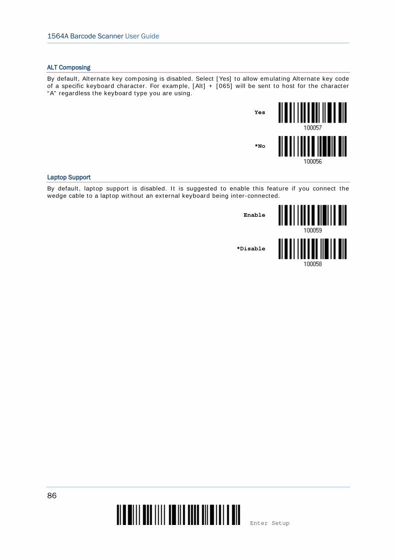
86
Enter Setup
1564A Barcode Scanner User Guide
ALT Composing
By default, Alternate key composing is disabled. Select [Yes] to allow emulating Alternate key code of a specific keyboard character. For example, [Alt] + [065] will be sent to host for the character “A” regardless the keyboard type you are using.
Yes
*No
Laptop Support
By default, laptop support is disabled. It is suggested to enable this feature if you connect the wedge cable to a laptop without an external keyboard being inter-connected.
Enable
*Disable
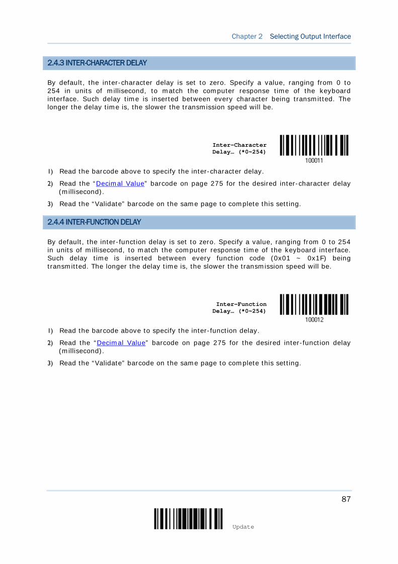
87
Update
Chapter 2 Selecting Output Interface
2.4.3 INTER-CHARACTER DELAY
By default, the inter-character delay is set to zero. Specify a value, ranging from 0 to 254 in units of millisecond, to match the computer response time of the keyboard interface. Such delay time is inserted between every character being transmitted. The longer the delay time is, the slower the transmission speed will be.
Inter-Character Delay… (*0~254)
1) Read the barcode above to specify the inter-character delay.
2) Read the “Decimal Value” barcode on page 275 for the desired inter-character delay (millisecond).
3) Read the “Validate” barcode on the same page to complete this setting.
2.4.4 INTER-FUNCTION DELAY
By default, the inter-function delay is set to zero. Specify a value, ranging from 0 to 254 in units of millisecond, to match the computer response time of the keyboard interface. Such delay time is inserted between every function code (0x01 ~ 0x1F) being transmitted. The longer the delay time is, the slower the transmission speed will be.
Inter-Function
Delay… (*0~254)
1) Read the barcode above to specify the inter-function delay.
2) Read the “Decimal Value” barcode on page 275 for the desired inter-function delay (millisecond).
3) Read the “Validate” barcode on the same page to complete this setting.
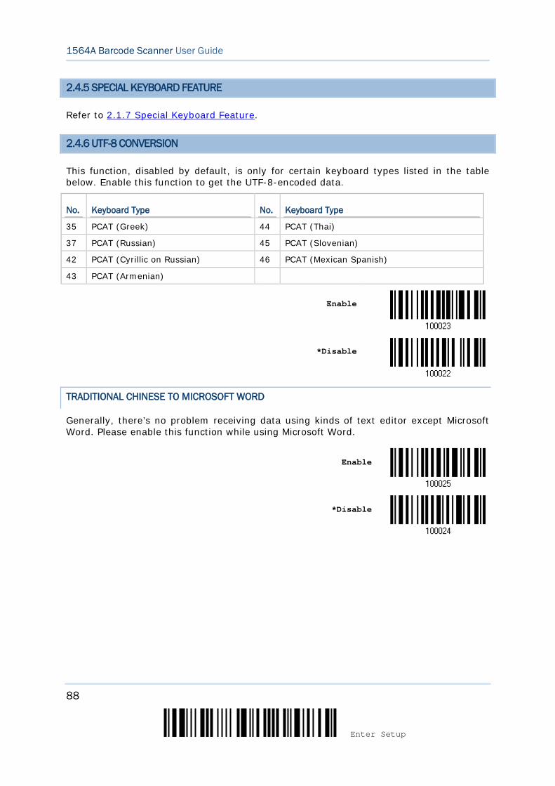
88
Enter Setup
1564A Barcode Scanner User Guide
2.4.5 SPECIAL KEYBOARD FEATURE
Refer to 2.1.7 Special Keyboard Feature.
2.4.6 UTF-8 CONVERSION
This function, disabled by default, is only for certain keyboard types listed in the table below. Enable this function to get the UTF-8-encoded data.
No. Keyboard Type No. Keyboard Type
35 PCAT (Greek) 44 PCAT (Thai)
37 PCAT (Russian) 45 PCAT (Slovenian)
42 PCAT (Cyrillic on Russian) 46 PCAT (Mexican Spanish)
43 PCAT (Armenian)
Enable
*Disable
TRADITIONAL CHINESE TO MICROSOFT WORD
Generally, there’s no problem receiving data using kinds of text editor except Microsoft Word. Please enable this function while using Microsoft Word.
Enable
*Disable
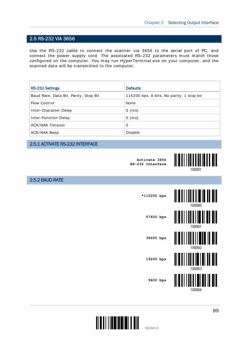
89
Update
Chapter 2 Selecting Output Interface
2.5 RS-232 VIA 3656
Use the RS-232 cable to connect the scanner via 3656 to the serial port of PC, and connect the power supply cord. The associated RS-232 parameters must match those configured on the computer. You may run HyperTerminal.exe on your computer, and the scanned data will be transmitted to the computer.
RS-232 Settings Defaults
Baud Rate, Data Bit, Parity, Stop Bit 115200 bps, 8 bits, No parity, 1 stop bit
Flow Control None
Inter-Character Delay 0 (ms)
Inter-Function Delay 0 (ms)
ACK/NAK Timeout 0
ACK/NAK Beep Disable
2.5.1 ACTIVATE RS-232 INTERFACE
Activate 3656
RS-232 Interface
2.5.2 BAUD RATE
*115200 bps
57600 bps
38400 bps
19200 bps
9600 bps
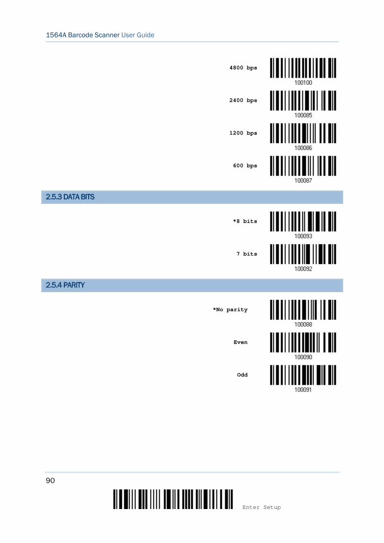
90
Enter Setup
1564A Barcode Scanner User Guide
4800 bps
2400 bps
1200 bps
600 bps
2.5.3 DATA BITS
*8 bits
7 bits
2.5.4 PARITY
*No parity
Even
Odd
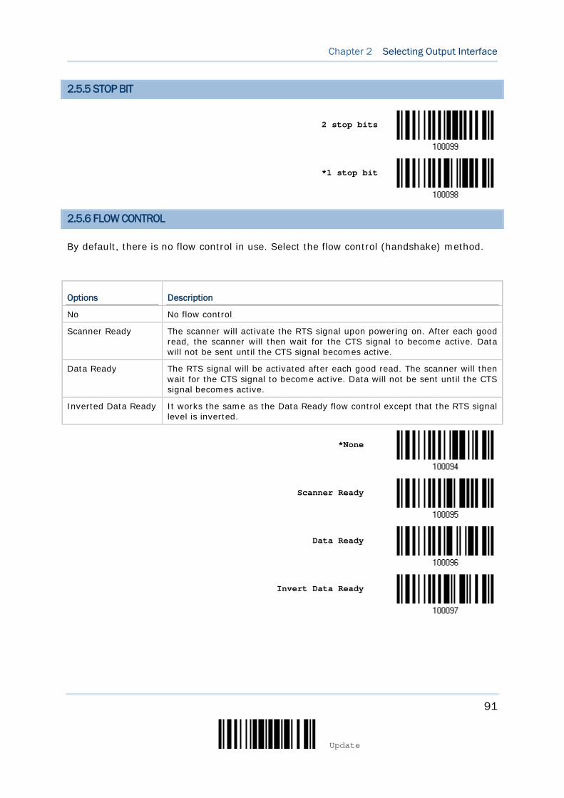
91
Update
Chapter 2 Selecting Output Interface
2.5.5 STOP BIT
2 stop bits
*1 stop bit
2.5.6 FLOW CONTROL
By default, there is no flow control in use. Select the flow control (handshake) method.
Options Description
No No flow control
Scanner Ready The scanner will activate the RTS signal upon powering on. After each good read, the scanner will then wait for the CTS signal to become active. Data will not be sent until the CTS signal becomes active.
Data Ready The RTS signal will be activated after each good read. The scanner will then wait for the CTS signal to become active. Data will not be sent until the CTS signal becomes active.
Inverted Data Ready It works the same as the Data Ready flow control except that the RTS signal level is inverted.
*None
Scanner Ready
Data Ready
Invert Data Ready
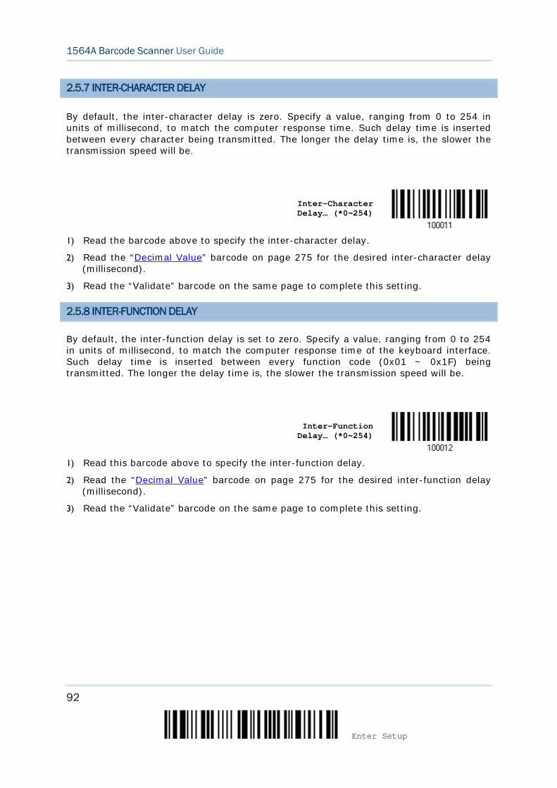
92
Enter Setup
1564A Barcode Scanner User Guide
2.5.7 INTER-CHARACTER DELAY
By default, the inter-character delay is zero. Specify a value, ranging from 0 to 254 in units of millisecond, to match the computer response time. Such delay time is inserted between every character being transmitted. The longer the delay time is, the slower the transmission speed will be.
Inter-Character Delay… (*0~254)
1) Read the barcode above to specify the inter-character delay.
2) Read the “Decimal Value” barcode on page 275 for the desired inter-character delay (millisecond).
3) Read the “Validate” barcode on the same page to complete this setting.
2.5.8 INTER-FUNCTION DELAY
By default, the inter-function delay is set to zero. Specify a value, ranging from 0 to 254 in units of millisecond, to match the computer response time of the keyboard interface. Such delay time is inserted between every function code (0x01 ~ 0x1F) being transmitted. The longer the delay time is, the slower the transmission speed will be.
Inter-Function
Delay… (*0~254)
1) Read this barcode above to specify the inter-function delay.
2) Read the “Decimal Value” barcode on page 275 for the desired inter-function delay (millisecond).
3) Read the “Validate” barcode on the same page to complete this setting.

93
Update
Chapter 2 Selecting Output Interface
2.5.9 ACK/NAK TIMEOUT
By default, the scanner sends data to the host without waiting for an ACK/NAK response before sending more data. Specify a value, ranging from 1 to 99 in units of 0.1 second. If no response within the specified period of time, the scanner will attempt to send the same data two more times. If all three attempts fail without any notification, data loss will occur.
ACK/NAK Time-out after … (*0~99)
1) Read the barcode above to specify the time interval for the scanner to send data and
wait for a response from the host.
2) Read the “Decimal Value” barcode on page 275. For example, read “1” and “0” for the scanner to automatically shut down after being idle for 1 second.
3) Read the “Validate” barcode on the same page to complete this setting.
ACK/NAK Error Beep
Enable Error Beep
*Disable Error Beep
Note: We suggest enabling the error beep so that you will be notified of such data loss and have the scanner re-read data.
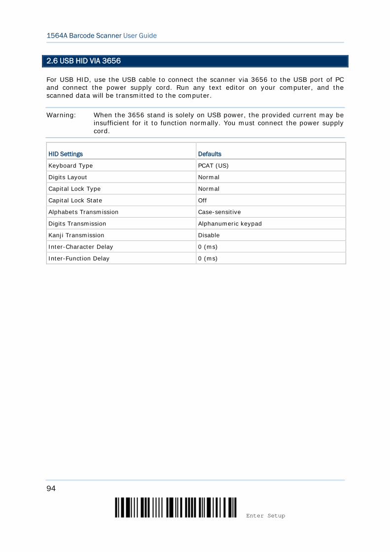
94
Enter Setup
1564A Barcode Scanner User Guide
2.6 USB HID VIA 3656
For USB HID, use the USB cable to connect the scanner via 3656 to the USB port of PC and connect the power supply cord. Run any text editor on your computer, and the scanned data will be transmitted to the computer.
Warning: When the 3656 stand is solely on USB power, the provided current may be insufficient for it to function normally. You must connect the power supply cord.
HID Settings Defaults
Keyboard Type PCAT (US)
Digits Layout Normal
Capital Lock Type Normal
Capital Lock State Off
Alphabets Transmission Case-sensitive
Digits Transmission Alphanumeric keypad
Kanji Transmission Disable
Inter-Character Delay 0 (ms)
Inter-Function Delay 0 (ms)
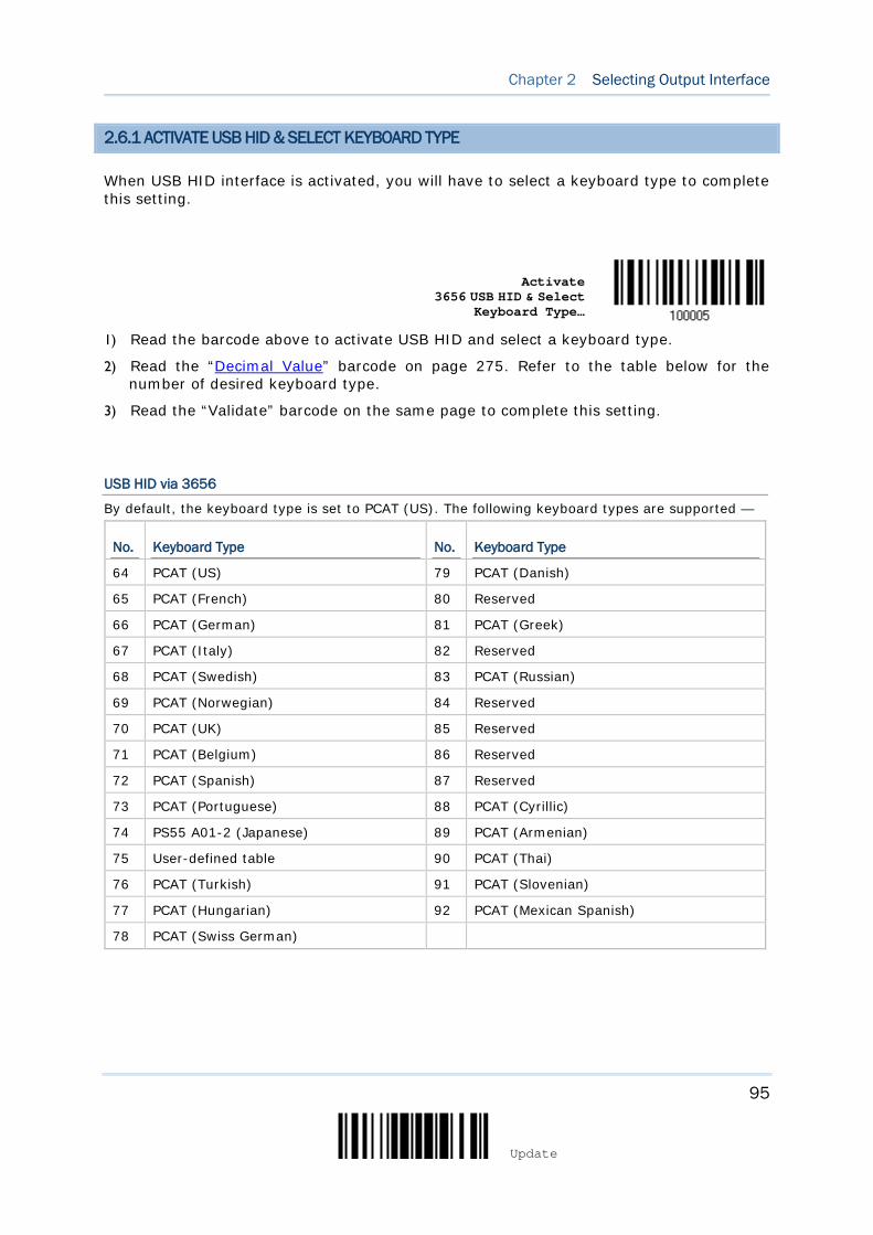
95
Update
Chapter 2 Selecting Output Interface
2.6.1 ACTIVATE USB HID & SELECT KEYBOARD TYPE
When USB HID interface is activated, you will have to select a keyboard type to complete this setting.
Activate
3656 USB HID & Select Keyboard Type…
1) Read the barcode above to activate USB HID and select a keyboard type.
2) Read the “Decimal Value” barcode on page 275. Refer to the table below for the number of desired keyboard type.
3) Read the “Validate” barcode on the same page to complete this setting.
USB HID via 3656
By default, the keyboard type is set to PCAT (US). The following keyboard types are supported —
No. Keyboard Type No. Keyboard Type
64 PCAT (US) 79 PCAT (Danish)
65 PCAT (French) 80 Reserved
66 PCAT (German) 81 PCAT (Greek)
67 PCAT (Italy) 82 Reserved
68 PCAT (Swedish) 83 PCAT (Russian)
69 PCAT (Norwegian) 84 Reserved
70 PCAT (UK) 85 Reserved
71 PCAT (Belgium) 86 Reserved
72 PCAT (Spanish) 87 Reserved
73 PCAT (Portuguese) 88 PCAT (Cyrillic)
74 PS55 A01-2 (Japanese) 89 PCAT (Armenian)
75 User-defined table 90 PCAT (Thai)
76 PCAT (Turkish) 91 PCAT (Slovenian)
77 PCAT (Hungarian) 92 PCAT (Mexican Spanish)
78 PCAT (Swiss German)
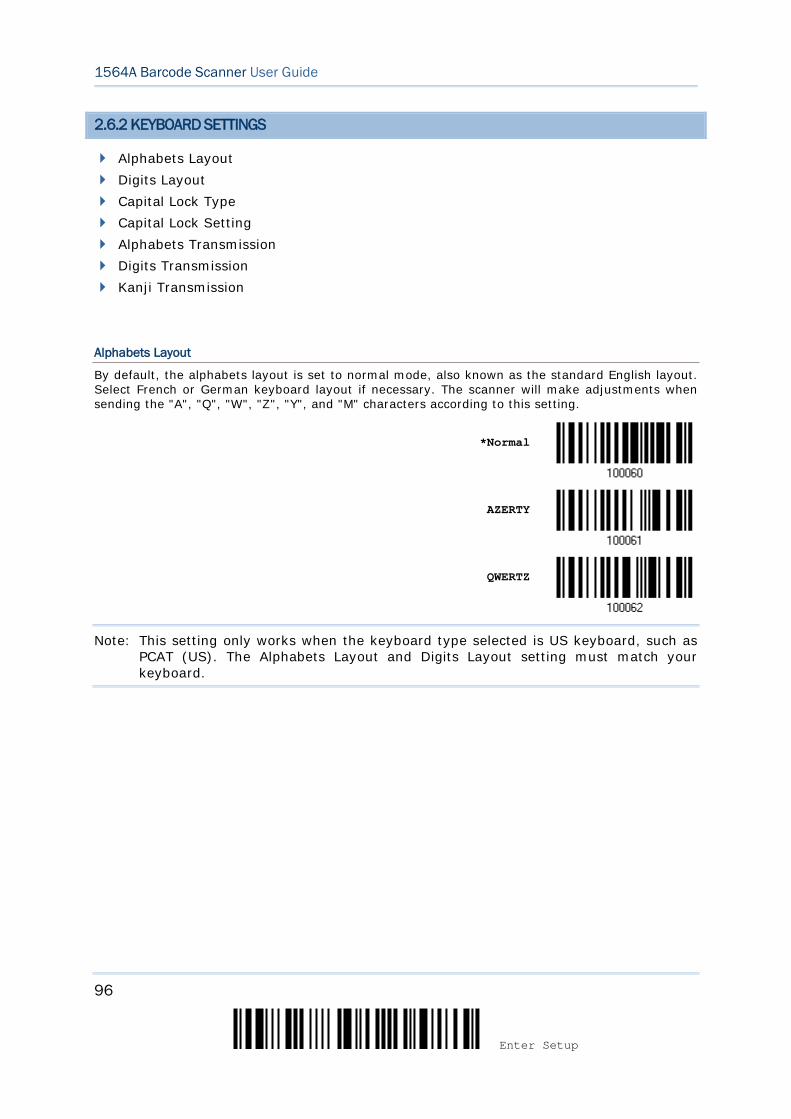
96
Enter Setup
1564A Barcode Scanner User Guide
2.6.2 KEYBOARD SETTINGS
Alphabets Layout Digits Layout Capital Lock Type Capital Lock Setting Alphabets Transmission Digits Transmission Kanji Transmission
Alphabets Layout
By default, the alphabets layout is set to normal mode, also known as the standard English layout. Select French or German keyboard layout if necessary. The scanner will make adjustments when sending the "A", "Q", "W", "Z", "Y", and "M" characters according to this setting.
*Normal
AZERTY
QWERTZ
Note: This setting only works when the keyboard type selected is US keyboard, such as PCAT (US). The Alphabets Layout and Digits Layout setting must match your keyboard.

97
Update
Chapter 2 Selecting Output Interface
US Keyboard Style – Normal
QWERTY layout, which is normally used in western countries.
Select “Lower Row” for the “Digits Layout” setting for the upper row is for special characters.
French Keyboard Style – AZERTY
French layout; see below for French Keyboard Style.
Select “Upper Row” for the “Digits Layout” setting for the lower row is for special characters.
German Keyboard Layout – QWERTZ
German layout; see below for German Keyboard Style.
Select “Lower Row” for the “Digits Layout” setting for the upper row is for special characters.
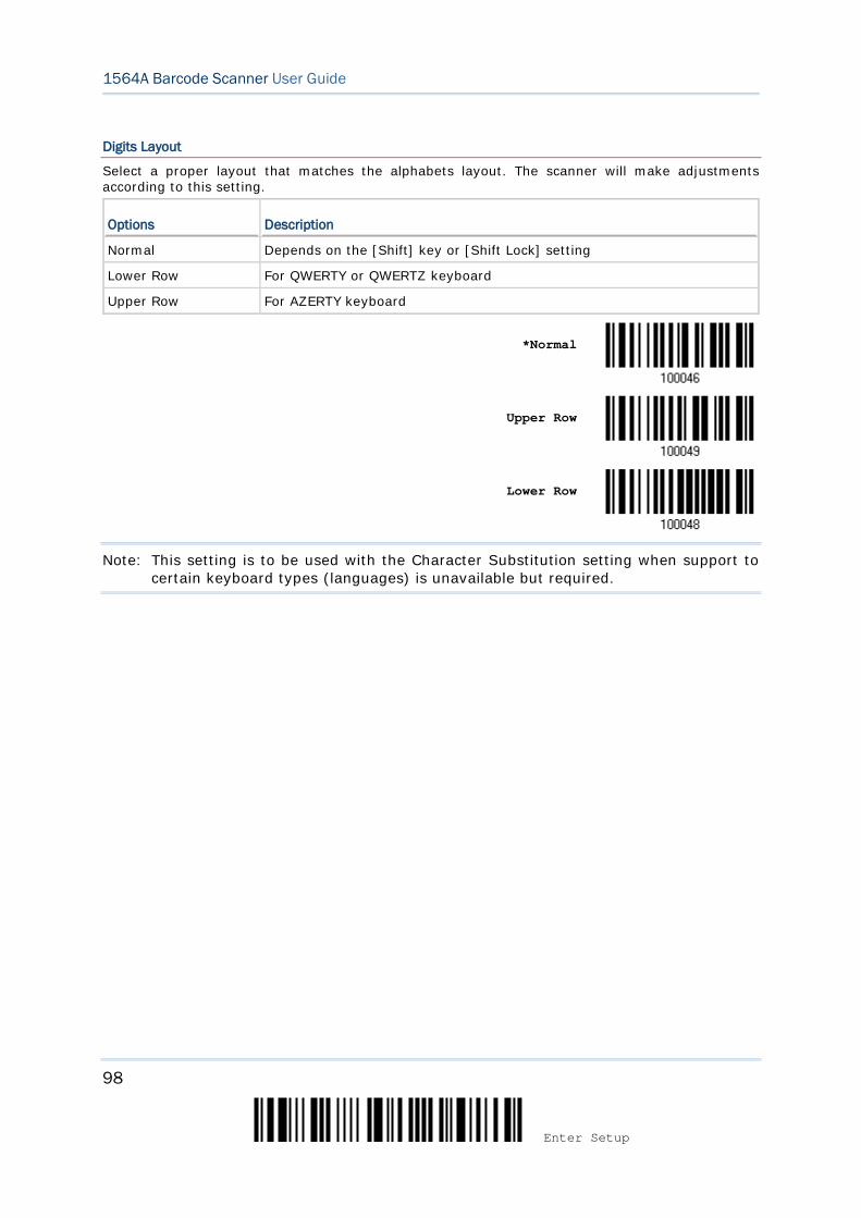
98
Enter Setup
1564A Barcode Scanner User Guide
Digits Layout
Select a proper layout that matches the alphabets layout. The scanner will make adjustments according to this setting.
Options Description
Normal Depends on the [Shift] key or [Shift Lock] setting
Lower Row For QWERTY or QWERTZ keyboard
Upper Row For AZERTY keyboard
*Normal
Upper Row
Lower Row
Note: This setting is to be used with the Character Substitution setting when support to certain keyboard types (languages) is unavailable but required.

99
Update
Chapter 2 Selecting Output Interface
Capital Lock Type & Setting
In order to send the alphabets with correct case, the scanner needs to know the status of Caps Lock on the keyboard. Incorrect settings may result in reversed case of the alphabets being transmitted.
Cap Lock Type Description
Normal Normal type
Capital Lock When enabled, the keys of alphabetic characters will be interpreted as capital letters. However, this does not affect the number or punctuation keys.
Shift Lock When enabled, the keys of alphabetic characters will be interpreted as capital letters. In addition, this affects the number or punctuation keys.
*Normal
Shift Lock
Capital Lock
Capital Lock State Description
Capital Lock OFF Assuming that the status of Caps Lock on the keyboard is OFF, transmitted characters are exactly the same as in the barcode (when "case-sensitive" is selected for Alphabets Transmission).
Capital Lock ON Assuming that the status of Caps Lock on the keyboard is ON, transmitted characters are exactly the same as in the barcode (when "case-sensitive" is selected for Alphabets Transmission).
Refer to the Capital Lock Type above.
Auto Detection The scanner will automatically detect the status of Caps Lock on the keyboard before data is transmitted; transmitted characters are exactly the same as in the barcode (when "case-sensitive" is selected for Alphabets Transmission).
Auto Detect
Capital Lock ON

100
Enter Setup
1564A Barcode Scanner User Guide
*Capital Lock OFF
Alphabets Transmission
By default, the alphabets transmission is case-sensitive, meaning that the alphabets will be transmitted according to their original case, the status of Caps Lock on the keyboard, as well as the Capital Lock setting. Select [Ignore Case] to have alphabets transmitted according to the status of Caps Lock on the keyboard only.
Ignore Case
*Case-sensitive
Refer to 5.1 Letter Case.
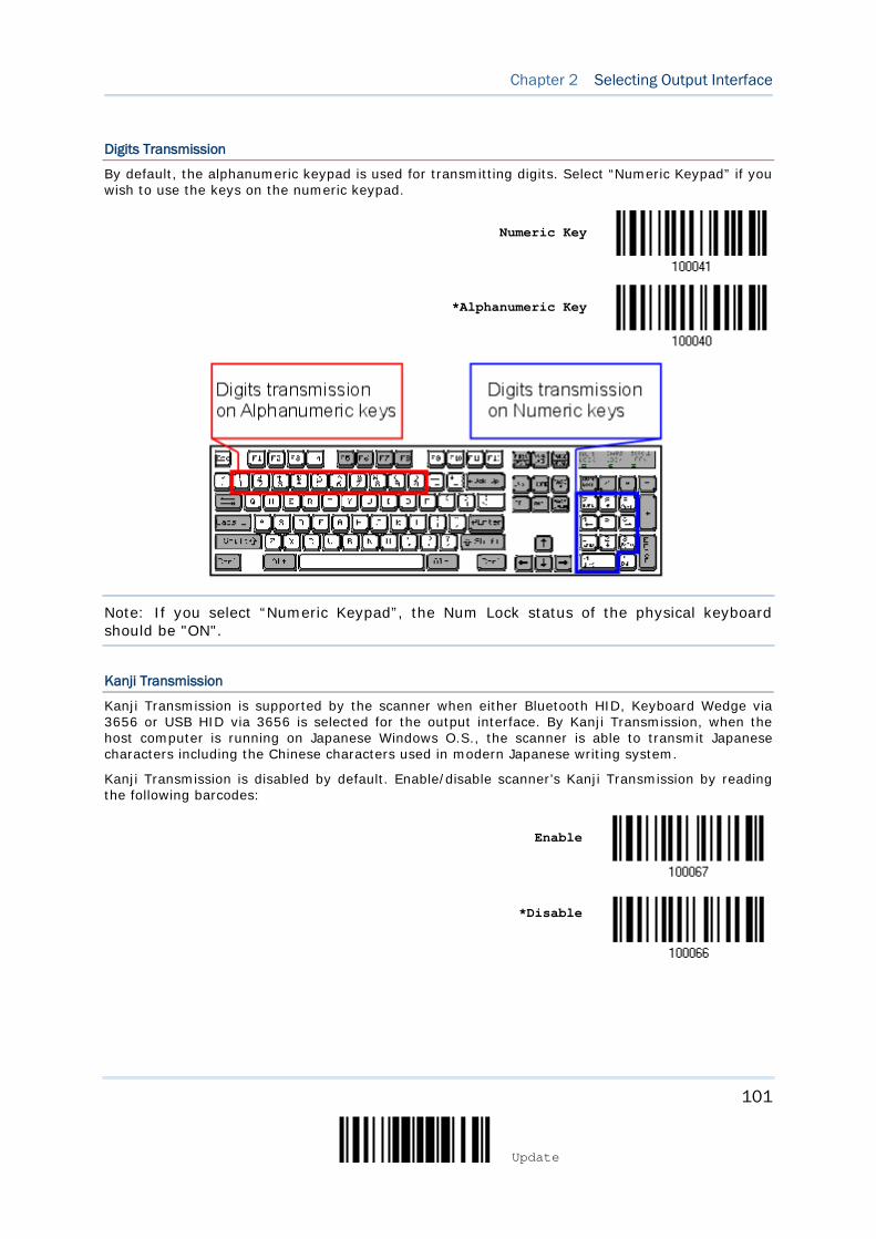
101
Update
Chapter 2 Selecting Output Interface
Digits Transmission
By default, the alphanumeric keypad is used for transmitting digits. Select “Numeric Keypad” if you wish to use the keys on the numeric keypad.
Numeric Key
*Alphanumeric Key
Note: If you select “Numeric Keypad”, the Num Lock status of the physical keyboard should be "ON".
Kanji Transmission
Kanji Transmission is supported by the scanner when either Bluetooth HID, Keyboard Wedge via 3656 or USB HID via 3656 is selected for the output interface. By Kanji Transmission, when the host computer is running on Japanese Windows O.S., the scanner is able to transmit Japanese characters including the Chinese characters used in modern Japanese writing system.
Kanji Transmission is disabled by default. Enable/disable scanner’s Kanji Transmission by reading the following barcodes:
Enable
*Disable

102
Enter Setup
1564A Barcode Scanner User Guide
2.6.3 INTER-CHARACTER DELAY
By default, the inter-character delay is set to zero. Specify a value, ranging from 0 to 254 in units of millisecond, to match the computer response time of the keyboard interface. Such delay time is inserted between every character being transmitted. The longer the delay time is, the slower the transmission speed will be.
Inter-Character Delay… (*0~254)
1) Read the barcode above to specify the inter-character delay.
2) Read the “Decimal Value” barcode on page 275 for the desired inter-character delay (millisecond).
3) Read the “Validate” barcode on the same page to complete this setting.
2.6.4 INTER-FUNCTION DELAY
By default, the inter-function delay is set to zero. Specify a value, ranging from 0 to 254 in units of millisecond, to match the computer response time of the keyboard interface. Such delay time is inserted between every function code (0x01 ~ 0x1F) being transmitted. The longer the delay time is, the slower the transmission speed will be.
Inter-Function
Delay… (*0~254)
1) Read the barcode above to specify the inter-function delay.
2) Read the “Decimal Value” barcode on page 275 for the desired inter-function delay (millisecond).
3) Read the “Validate” barcode on the same page to complete this setting.
103
Update
Chapter 2 Selecting Output Interface
2.6.5 HID CHARACTER TRANSMIT MODE
Refer to 2.1.6 HID Character Transmit Mode.
2.6.6 SPECIAL KEYBOARD FEATURE
Refer to 2.1.7 Special Keyboard Feature.
2.6.7 USB HID VIA 3656 AUTO-RECONNECTION
Users can decide whether to have the scanner automatically reconnect to a paired device after disconnection, and the occasion for reconnecting.
*Auto reconnect
immediately
Auto reconnect on data scanned
Auto reconnect off
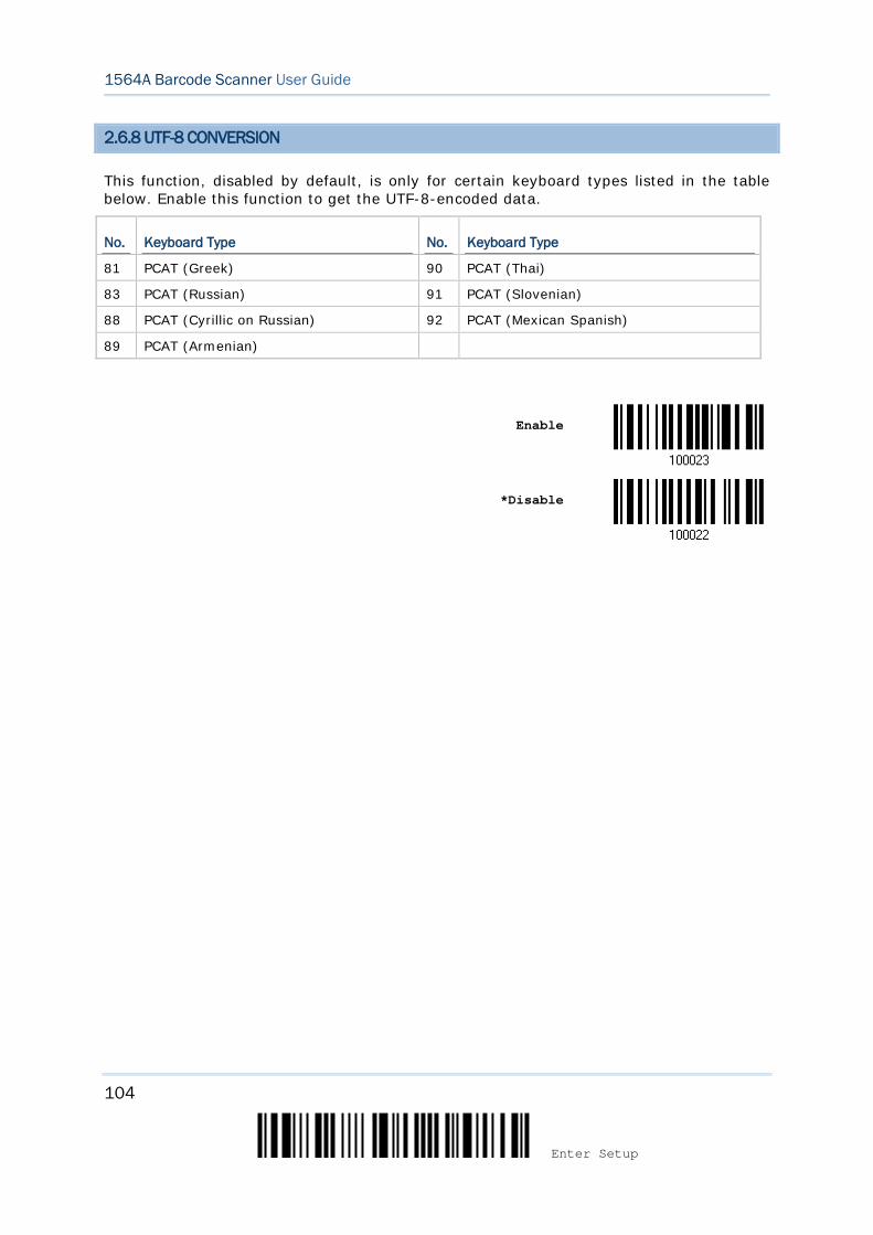
104
Enter Setup
1564A Barcode Scanner User Guide
2.6.8 UTF-8 CONVERSION
This function, disabled by default, is only for certain keyboard types listed in the table below. Enable this function to get the UTF-8-encoded data.
No. Keyboard Type No. Keyboard Type
81 PCAT (Greek) 90 PCAT (Thai)
83 PCAT (Russian) 91 PCAT (Slovenian)
88 PCAT (Cyrillic on Russian) 92 PCAT (Mexican Spanish)
89 PCAT (Armenian)
Enable
*Disable
105
Update
Chapter 2 Selecting Output Interface
2.6.9 USB POLLING INTERVAL
Scan the barcodes below to specify the USB polling interval ranging from 1 to 15ms.
Set USB polling interval
1~15 ms(*4)
1) Read the barcode above to specify the USB polling interval time.
2) Read the “Decimal Value” barcode on page 275.
3) Read the “Validate” barcode on the same page to complete this setting.
106
Enter Setup
1564A Barcode Scanner User Guide
2.7 USB VIRTUAL COM VIA 3656
Use the USB cable to connect the scanner via 3656 to the USB port of PC and connect the power supply cord. You may run HyperTerminal.exe on your computer, and the scanned data will be transmitted to the computer.
Warning: When the 3656 stand is solely on USB power, the current may be insufficient for it to function normally. You must connect the power supply cord.
Note: If using USB Virtual COM for the first time, you must install its driver beforehand. Driver version 5.4 or later is required. Please remove older versions!
2.7.1 ACTIVATE USB VIRTUAL COM
Activate 3656
USB Virtual COM
2.7.2 INTER-FUNCTION DELAY
By default, the inter-function delay is set to zero. Specify a value, ranging from 0 to 254 in units of millisecond, to match the computer response time of the keyboard interface. Such delay time is inserted between every function code (0x01 ~ 0x1F) being transmitted. The longer the delay time is, the slower the transmission speed will be.
Inter-Function
Delay… (*0~254)
1) Read the barcode above to specify the inter-function delay.
2) Read the “Decimal Value” barcode on page 275 for the desired inter-function delay (millisecond).
3) Read the “Validate” barcode on the same page to complete this setting.
107
Update
Chapter 2 Selecting Output Interface
2.7.3 ACK/NAK TIMEOUT
By default, the scanner sends data to the host without waiting for an ACK/NAK response before sending more data. Specify a value, ranging from 1 to 99 in units of 0.1 second. If no response within the specified period of time, the scanner will attempt to send the same data two more times. If all three attempts fail without any notification, data loss will occur.
ACK/NAK Time-out after … (*0~99)
1) Read the barcode above to specify the time interval for the scanner to send data and
wait for a response from the host.
2) Read the “Decimal Value” barcode on page 275. For example, read “1” and “0” for the scanner to automatically shut down after being idle for 1 second.
3) Read the “Validate” barcode on the same page to complete this setting.
ACK/NAK Error Beep
Enable Error Beep
*Disable Error Beep
Note: We suggest enabling the error beep so that you will be notified of such data loss and have the scanner re-read data.
108
Enter Setup
1564A Barcode Scanner User Guide
2.7.4 USB VCOM VIA 3656 AUTO-RECONNECTION
Users can decide whether to have the scanner automatically reconnect to a paired device after disconnection, and the occasion for reconnecting.
*Auto reconnect
immediately
Auto reconnect on data scanned
Auto reconnect off
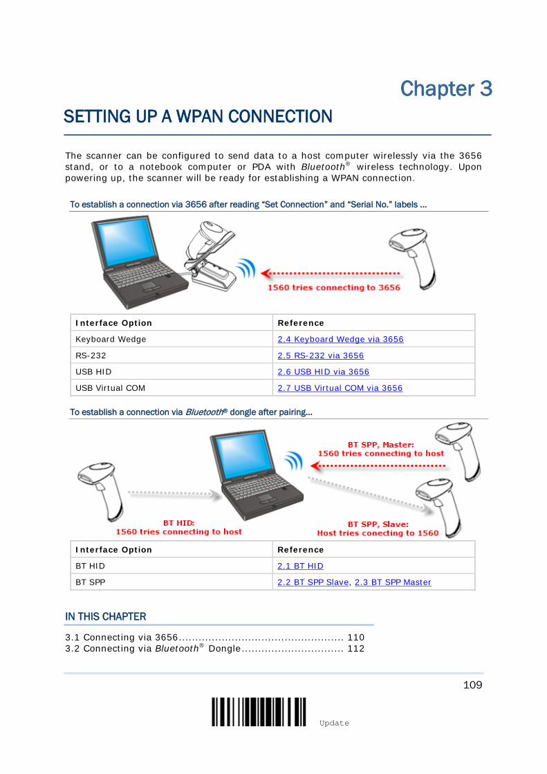
109
Update
The scanner can be configured to send data to a host computer wirelessly via the 3656 stand, or to a notebook computer or PDA with Bluetooth® wireless technology. Upon powering up, the scanner will be ready for establishing a WPAN connection.
To establish a connection via 3656 after reading “Set Connection” and “Serial No.” labels …
Interface Option Reference
Keyboard Wedge 2.4 Keyboard Wedge via 3656
RS-232 2.5 RS-232 via 3656
USB HID 2.6 USB HID via 3656
USB Virtual COM 2.7 USB Virtual COM via 3656
To establish a connection via Bluetooth® dongle after pairing…
Interface Option Reference
BT HID 2.1 BT HID
BT SPP 2.2 BT SPP Slave, 2.3 BT SPP Master
IN THIS CHAPTER
3.1 Connecting via 3656 .................................................. 110 3.2 Connecting via Bluetooth® Dongle ............................... 112
Chapter 3 SETTING UP A WPAN CONNECTION
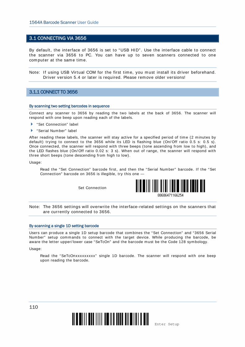
110
Enter Setup
1564A Barcode Scanner User Guide
3.1 CONNECTING VIA 3656
By default, the interface of 3656 is set to “USB HID”. Use the interface cable to connect the scanner via 3656 to PC. You can have up to seven scanners connected to one computer at the same time.
Note: If using USB Virtual COM for the first time, you must install its driver beforehand. Driver version 5.4 or later is required. Please remove older versions!
3.1.1 CONNECT TO 3656
By scanning two setting barcodes in sequence
Connect any scanner to 3656 by reading the two labels at the back of 3656. The scanner will respond with one beep upon reading each of the labels.
“Set Connection” label
“Serial Number” label
After reading these labels, the scanner will stay active for a specified period of time (2 minutes by default) trying to connect to the 3656 while its LED is flashing blue (On/Off ratio 0.5 s: 0.5 s). Once connected, the scanner will respond with three beeps (tone ascending from low to high), and the LED flashes blue (On/Off ratio 0.02 s: 3 s). When out of range, the scanner will respond with three short beeps (tone descending from high to low).
Usage:
Read the “Set Connection” barcode first, and then the “Serial Number” barcode. If the “Set Connection” barcode on 3656 is illegible, try this one —
Set Connection
Note: The 3656 settings will overwrite the interface-related settings on the scanners that are currently connected to 3656.
By scanning a single 1D setting barcode
Users can produce a single 1D setup barcode that combines the “Set Connection” and “3656 Serial Number” setup commands to connect with the target device. While producing the barcode, be aware the letter upper/lower case “SeTcOn” and the barcode must be the Code 128 symbology.
Usage:
Read the “SeTcOnxxxxxxxxx” single 1D barcode. The scanner will respond with one beep upon reading the barcode.
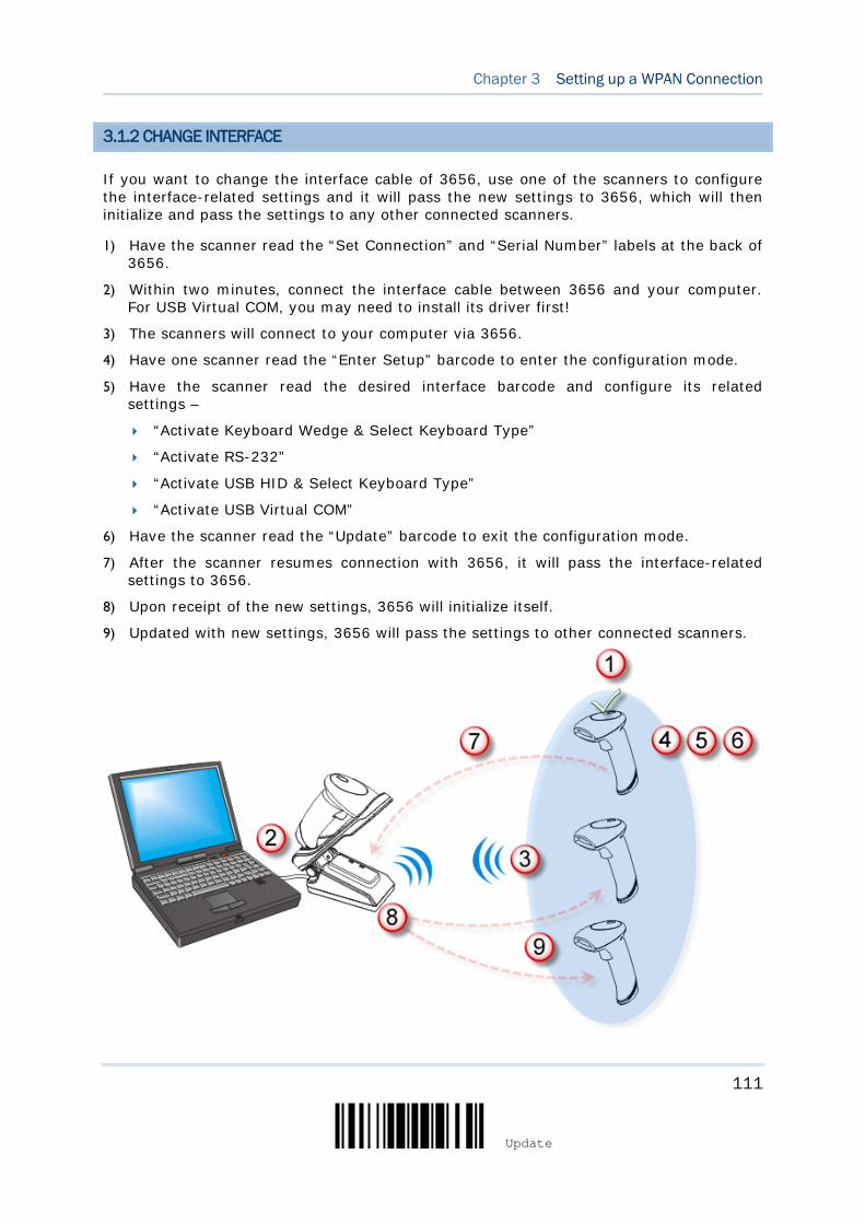
111
Update
Chapter 3 Setting up a WPAN Connection
3.1.2 CHANGE INTERFACE
If you want to change the interface cable of 3656, use one of the scanners to configure the interface-related settings and it will pass the new settings to 3656, which will then initialize and pass the settings to any other connected scanners.
1) Have the scanner read the “Set Connection” and “Serial Number” labels at the back of 3656.
2) Within two minutes, connect the interface cable between 3656 and your computer. For USB Virtual COM, you may need to install its driver first!
3) The scanners will connect to your computer via 3656.
4) Have one scanner read the “Enter Setup” barcode to enter the configuration mode.
5) Have the scanner read the desired interface barcode and configure its related settings –
“Activate Keyboard Wedge & Select Keyboard Type”
“Activate RS-232”
“Activate USB HID & Select Keyboard Type”
“Activate USB Virtual COM”
6) Have the scanner read the “Update” barcode to exit the configuration mode.
7) After the scanner resumes connection with 3656, it will pass the interface-related settings to 3656.
8) Upon receipt of the new settings, 3656 will initialize itself.
9) Updated with new settings, 3656 will pass the settings to other connected scanners.
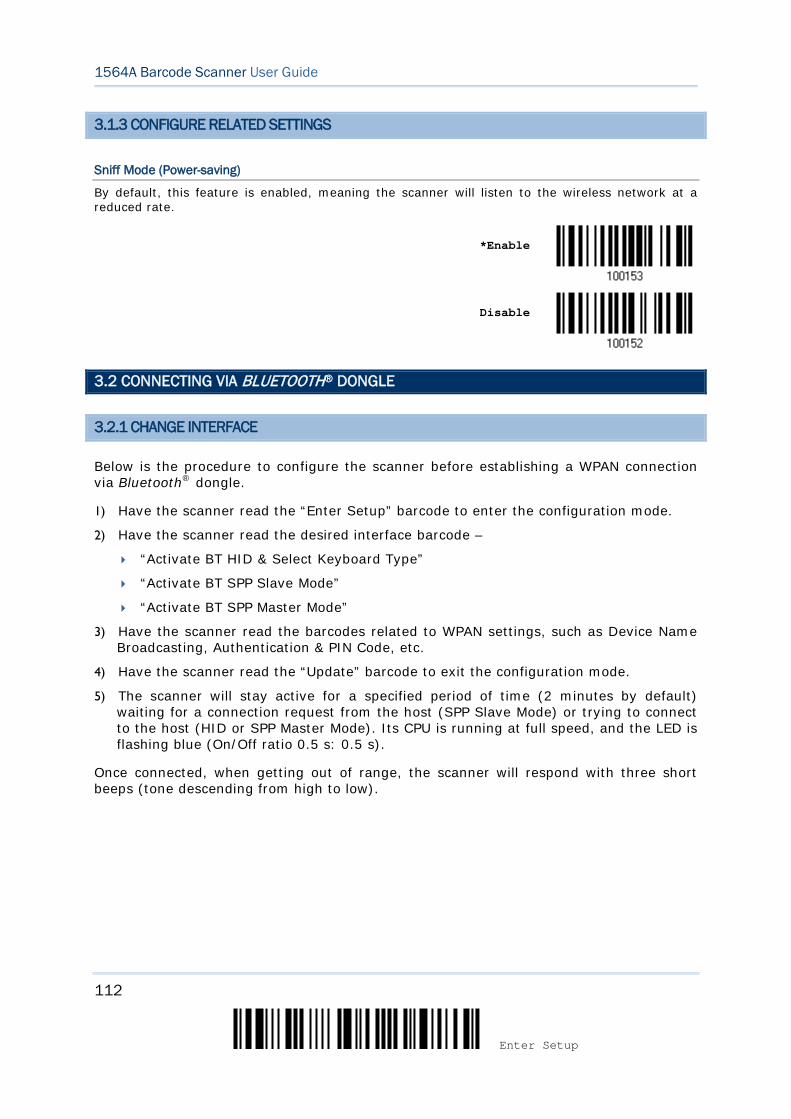
112
Enter Setup
1564A Barcode Scanner User Guide
3.1.3 CONFIGURE RELATED SETTINGS
Sniff Mode (Power-saving)
By default, this feature is enabled, meaning the scanner will listen to the wireless network at a reduced rate.
*Enable
Disable
3.2 CONNECTING VIA BLUETOOTH® DONGLE
3.2.1 CHANGE INTERFACE
Below is the procedure to configure the scanner before establishing a WPAN connection via Bluetooth® dongle.
1) Have the scanner read the “Enter Setup” barcode to enter the configuration mode.
2) Have the scanner read the desired interface barcode –
“Activate BT HID & Select Keyboard Type”
“Activate BT SPP Slave Mode”
“Activate BT SPP Master Mode”
3) Have the scanner read the barcodes related to WPAN settings, such as Device Name Broadcasting, Authentication & PIN Code, etc.
4) Have the scanner read the “Update” barcode to exit the configuration mode.
5) The scanner will stay active for a specified period of time (2 minutes by default) waiting for a connection request from the host (SPP Slave Mode) or trying to connect to the host (HID or SPP Master Mode). Its CPU is running at full speed, and the LED is flashing blue (On/Off ratio 0.5 s: 0.5 s).
Once connected, when getting out of range, the scanner will respond with three short beeps (tone descending from high to low).
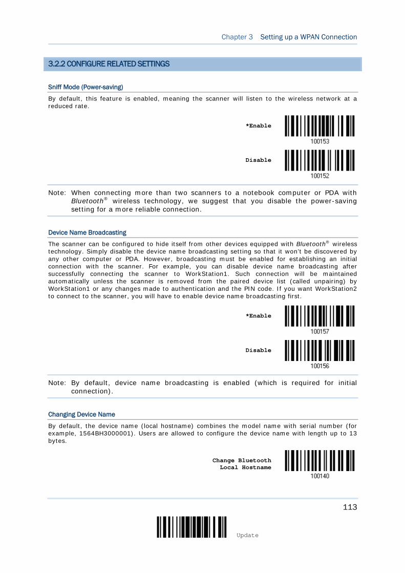
113
Update
Chapter 3 Setting up a WPAN Connection
3.2.2 CONFIGURE RELATED SETTINGS
Sniff Mode (Power-saving)
By default, this feature is enabled, meaning the scanner will listen to the wireless network at a reduced rate.
*Enable
Disable
Note: When connecting more than two scanners to a notebook computer or PDA with Bluetooth® wireless technology, we suggest that you disable the power-saving setting for a more reliable connection.
Device Name Broadcasting
The scanner can be configured to hide itself from other devices equipped with Bluetooth® wireless technology. Simply disable the device name broadcasting setting so that it won’t be discovered by any other computer or PDA. However, broadcasting must be enabled for establishing an initial connection with the scanner. For example, you can disable device name broadcasting after successfully connecting the scanner to WorkStation1. Such connection will be maintained automatically unless the scanner is removed from the paired device list (called unpairing) by WorkStation1 or any changes made to authentication and the PIN code. If you want WorkStation2 to connect to the scanner, you will have to enable device name broadcasting first.
*Enable
Disable
Note: By default, device name broadcasting is enabled (which is required for initial connection).
Changing Device Name
By default, the device name (local hostname) combines the model name with serial number (for example, 1564BH3000001). Users are allowed to configure the device name with length up to 13 bytes.
Change Bluetooth
Local Hostname

114
Enter Setup
1564A Barcode Scanner User Guide
1) Read the barcode above to configure the device name.
2) Read the “Hexadecimal Value” barcode on page 276 for the desired character string.
3) Read the “Validate” barcode to complete this setting.
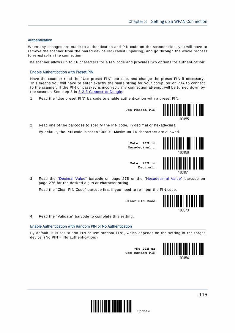
115
Update
Chapter 3 Setting up a WPAN Connection
Authentication
When any changes are made to authentication and PIN code on the scanner side, you will have to remove the scanner from the paired device list (called unpairing) and go through the whole process to re-establish the connection.
The scanner allows up to 16 characters for a PIN code and provides two options for authentication:
Enable Authentication with Preset PIN
Have the scanner read the “Use preset PIN” barcode, and change the preset PIN if necessary. This means you will have to enter exactly the same string for your computer or PDA to connect to the scanner. If the PIN or passkey is incorrect, any connection attempt will be turned down by the scanner. See step 8 in 3.2.3 Connect to Dongle.
1. Read the “Use preset PIN” barcode to enable authentication with a preset PIN.
Use Preset PIN
2. Read one of the barcodes to specify the PIN code, in decimal or hexadecimal.
By default, the PIN code is set to “0000”. Maximum 16 characters are allowed.
Enter PIN in Hexadecimal …
Enter PIN in Decimal…
3. Read the “Decimal Value” barcode on page 275 or the “Hexadecimal Value” barcode on
page 276 for the desired digits or character string.
Read the “Clear PIN Code” barcode first if you need to re-input the PIN code.
Clear PIN Code
4. Read the “Validate” barcode to complete this setting.
Enable Authentication with Random PIN or No Authentication
By default, it is set to “No PIN or use random PIN”, which depends on the setting of the target device. (No PIN = No authentication.)
*No PIN or
use random PIN
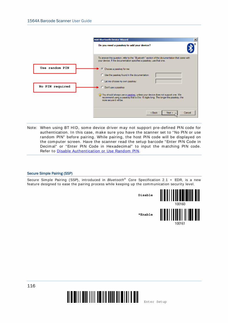
116
Enter Setup
1564A Barcode Scanner User Guide
Note: When using BT HID, some device driver may not support pre-defined PIN code for authentication. In this case, make sure you have the scanner set to “No PIN or use random PIN” before pairing. While pairing, the host PIN code will be displayed on the computer screen. Have the scanner read the setup barcode “Enter PIN Code in Decimal” or “Enter PIN Code in Hexadecimal” to input the matching PIN code. Refer to Disable Authentication or Use Random PIN.
Secure Simple Pairing (SSP)
Secure Simple Pairing (SSP), introduced in Bluetooth® Core Specification 2.1 + EDR, is a new feature designed to ease the pairing process while keeping up the communication security level.
Disable
*Enable
Use random PIN
No PIN required

117
Update
Chapter 3 Setting up a WPAN Connection
3.2.3 CONNECT TO DONGLE
The procedure goes through associating devices for establishing a WPAN connection, which is pretty much the same except for the software you are using. If your computer is running Microsoft® Windows® XP Service Pack 3 (SP3) or Windows Vista® Service Pack 1 (SP1), you can use the software support that Windows® includes, or you can use the driver that the device manufacturer provides. Now, let’s try using the software support that Windows® XP Service Pack 2 includes.
BT HID Procedure
By default, BT HID is activated on the scanner, and the keyboard type is set to PCAT (US). When BT HID is re-activated, you will have to select a keyboard type to complete this setting.
The procedure is the same as for BT SPP. Refer to steps 1~11 below.
BT SPP Procedure
1. Turn on the Bluetooth® function on your computer, running Windows XP SP2.
2. Double-click the Bluetooth® icon from the lower right of the taskbar.
Alternatively, you may go to Control Panel > Bluetooth Devices.
3. Click [Add] to search devices nearby.
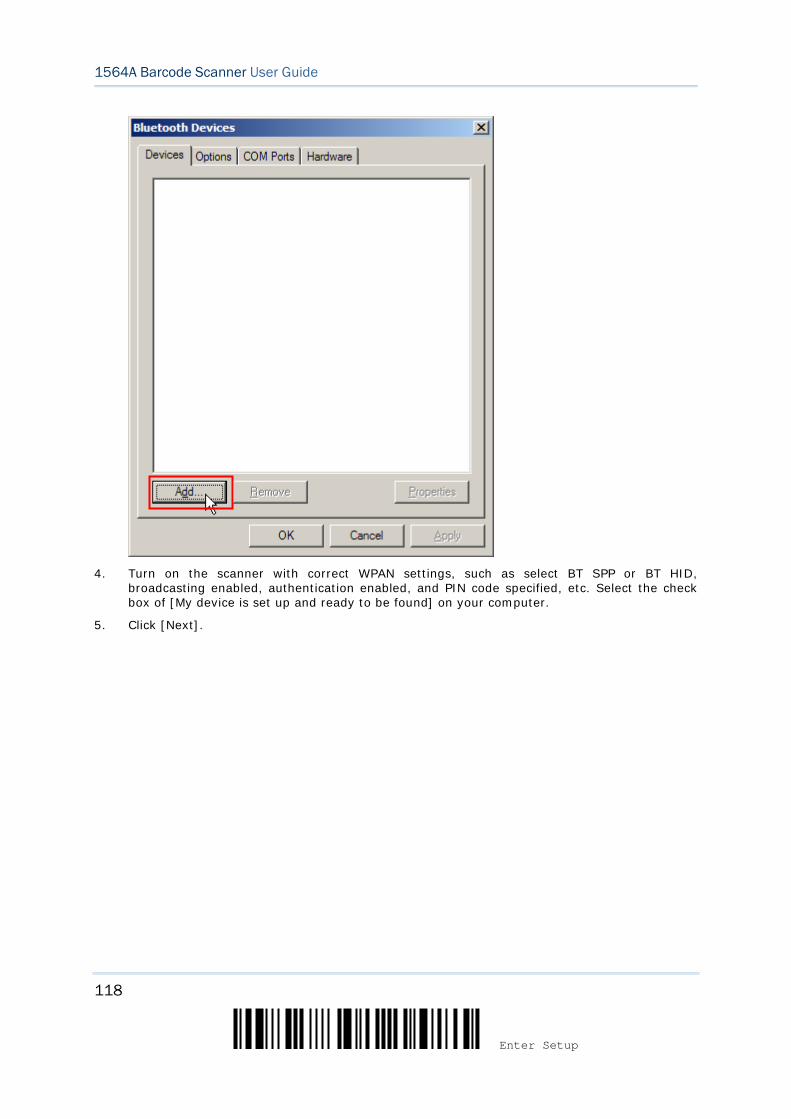
118
Enter Setup
1564A Barcode Scanner User Guide
4. Turn on the scanner with correct WPAN settings, such as select BT SPP or BT HID,
broadcasting enabled, authentication enabled, and PIN code specified, etc. Select the check box of [My device is set up and ready to be found] on your computer.
5. Click [Next].
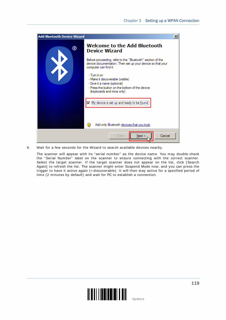
119
Update
Chapter 3 Setting up a WPAN Connection
6. Wait for a few seconds for the Wizard to search available devices nearby.
The scanner will appear with its “serial number” as the device name. You may double-check the “Serial Number” label on the scanner to ensure connecting with the correct scanner. Select the target scanner. If the target scanner does not appear on the list, click [Search Again] to refresh the list. The scanner might enter Suspend Mode now, and you can press the trigger to have it active again (=discoverable). It will then stay active for a specified period of time (2 minutes by default) and wait for PC to establish a connection.

120
Enter Setup
1564A Barcode Scanner User Guide
7. Click [Next].
8. Enter the passkey for authentication, which must be exactly the same as configured for the
scanner.
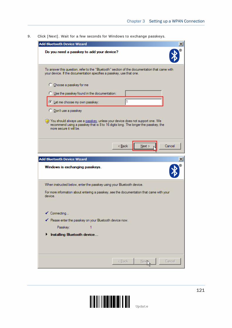
121
Update
Chapter 3 Setting up a WPAN Connection
9. Click [Next]. Wait for a few seconds for Windows to exchange passkeys.
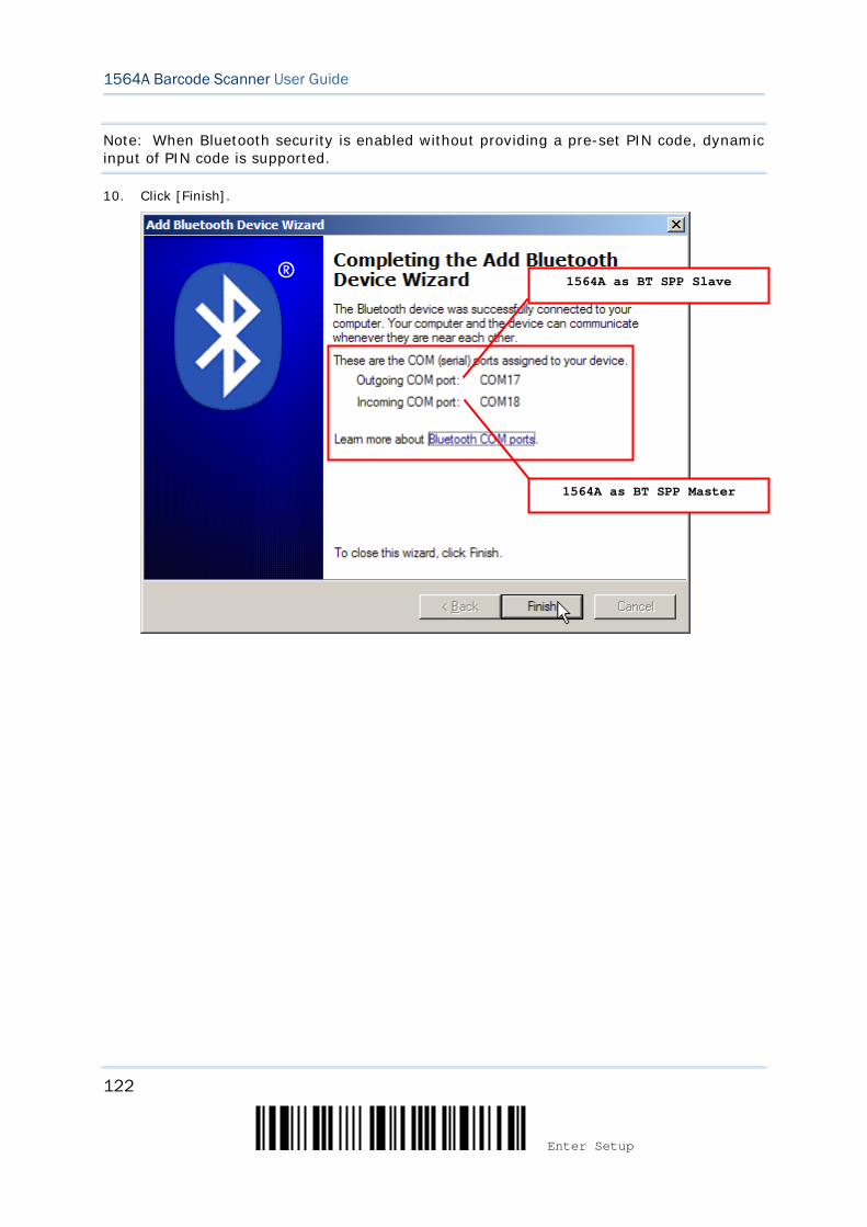
122
Enter Setup
1564A Barcode Scanner User Guide
Note: When Bluetooth security is enabled without providing a pre-set PIN code, dynamic input of PIN code is supported.
10. Click [Finish].
1564A as BT SPP Slave
1564A as BT SPP Master
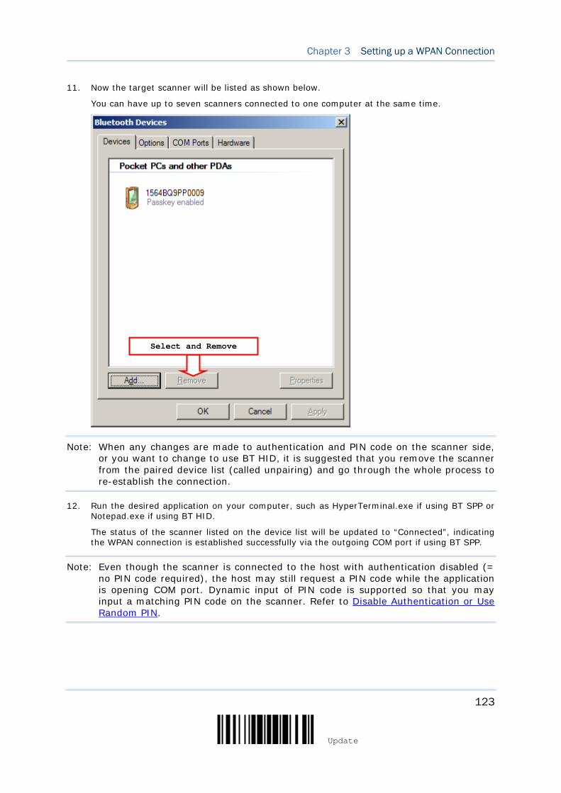
123
Update
Chapter 3 Setting up a WPAN Connection
11. Now the target scanner will be listed as shown below.
You can have up to seven scanners connected to one computer at the same time.
Note: When any changes are made to authentication and PIN code on the scanner side, or you want to change to use BT HID, it is suggested that you remove the scanner from the paired device list (called unpairing) and go through the whole process to re-establish the connection.
12. Run the desired application on your computer, such as HyperTerminal.exe if using BT SPP or Notepad.exe if using BT HID.
The status of the scanner listed on the device list will be updated to “Connected”, indicating the WPAN connection is established successfully via the outgoing COM port if using BT SPP.
Note: Even though the scanner is connected to the host with authentication disabled (= no PIN code required), the host may still request a PIN code while the application is opening COM port. Dynamic input of PIN code is supported so that you may input a matching PIN code on the scanner. Refer to Disable Authentication or Use Random PIN.
Select and Remove

124
Enter Setup
1564A Barcode Scanner User Guide
BT SPP Connected
BT SPP Disconnected
125
Update
In this chapter, a brief on the symbology settings is provided for your reference.
IN THIS CHAPTER
4.1 Codabar ................................................................... 126 4.2 Code 25 – Industrial 25 ............................................. 128 4.3 Code 25 – Interleaved 25 ........................................... 130 4.4 Code 25 – Matrix 25 .................................................. 133 4.5 Code 25 – Chinese 25 ................................................ 135 4.6 Italian Pharmacode (Code 32) ................................... 136 4.7 Code 39 ................................................................... 137 4.8 Trioptic Code 39 ....................................................... 140 4.9 Code 93 ................................................................... 141 4.10 Code 128 ............................................................... 142 4.11 GS1-128 (EAN-128) ............................................... 143 4.12 ISBT 128 ................................................................ 145 4.13 GS1 DataBar (RSS Family) ....................................... 147 4.14 MSI ....................................................................... 153 4.15 EAN-8 .................................................................... 155 4.16 EAN-13 .................................................................. 156 4.17 UCC Coupon Extended Code ..................................... 161 4.18 UPC-A .................................................................... 162 4.19 UPC-E .................................................................... 164 4.20 Code 11 ................................................................. 167 4.21 Composite Code ...................................................... 169 4.22 US Postal Code ....................................................... 173 4.23 UK Postal Code ....................................................... 174 4.24 More Postal Code .................................................... 175 4.25 2D Symbologies ...................................................... 176 4.26 Macro PDF .............................................................. 181
Chapter 4 CHANGING SYMBOLOGY SETTINGS
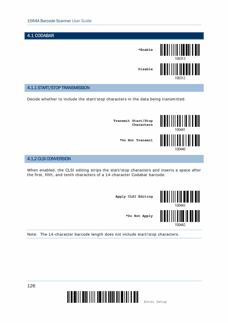
126
Enter Setup
1564A Barcode Scanner User Guide
4.1 CODABAR
*Enable
Disable
4.1.1 START/STOP TRANSMISSION
Decide whether to include the start/stop characters in the data being transmitted.
Transmit Start/Stop
Characters
*Do Not Transmit
4.1.2 CLSI CONVERSION
When enabled, the CLSI editing strips the start/stop characters and inserts a space after the first, fifth, and tenth characters of a 14-character Codabar barcode.
Apply CLSI Editing
*Do Not Apply
Note: The 14-character barcode length does not include start/stop characters.
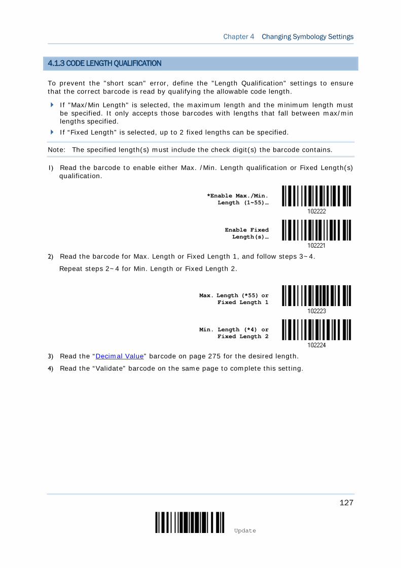
127
Update
Chapter 4 Changing Symbology Settings
4.1.3 CODE LENGTH QUALIFICATION
To prevent the "short scan" error, define the "Length Qualification" settings to ensure that the correct barcode is read by qualifying the allowable code length.
If "Max/Min Length" is selected, the maximum length and the minimum length must be specified. It only accepts those barcodes with lengths that fall between max/min lengths specified.
If “Fixed Length” is selected, up to 2 fixed lengths can be specified.
Note: The specified length(s) must include the check digit(s) the barcode contains.
1) Read the barcode to enable either Max. /Min. Length qualification or Fixed Length(s) qualification.
*Enable Max./Min.
Length (1~55)…
Enable Fixed Length(s)…
2) Read the barcode for Max. Length or Fixed Length 1, and follow steps 3~4.
Repeat steps 2~4 for Min. Length or Fixed Length 2.
Max. Length (*55) or
Fixed Length 1
Min. Length (*4) or Fixed Length 2
3) Read the “Decimal Value” barcode on page 275 for the desired length.
4) Read the “Validate” barcode on the same page to complete this setting.

128
Enter Setup
1564A Barcode Scanner User Guide
4.2 CODE 25 – INDUSTRIAL 25
*Enable
Disable
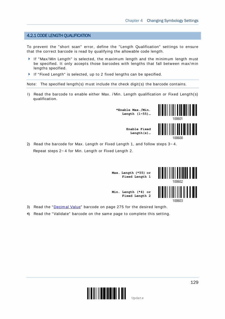
129
Update
Chapter 4 Changing Symbology Settings
4.2.1 CODE LENGTH QUALIFICATION
To prevent the "short scan" error, define the "Length Qualification" settings to ensure that the correct barcode is read by qualifying the allowable code length.
If "Max/Min Length" is selected, the maximum length and the minimum length must be specified. It only accepts those barcodes with lengths that fall between max/min lengths specified.
If “Fixed Length” is selected, up to 2 fixed lengths can be specified.
Note: The specified length(s) must include the check digit(s) the barcode contains.
1) Read the barcode to enable either Max. /Min. Length qualification or Fixed Length(s) qualification.
*Enable Max./Min.
Length (1~55)…
Enable Fixed Length(s)…
2) Read the barcode for Max. Length or Fixed Length 1, and follow steps 3~4.
Repeat steps 2~4 for Min. Length or Fixed Length 2.
Max. Length (*55) or
Fixed Length 1
Min. Length (*4) or Fixed Length 2
3) Read the “Decimal Value” barcode on page 275 for the desired length.
4) Read the “Validate” barcode on the same page to complete this setting.
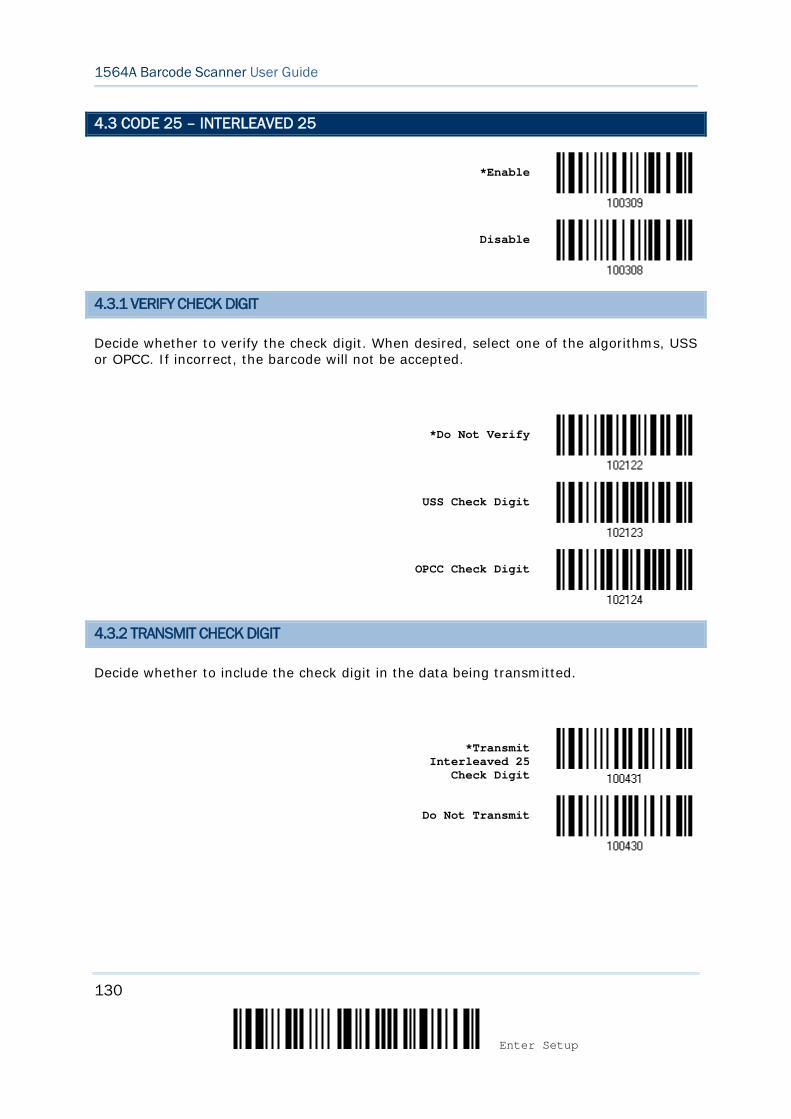
130
Enter Setup
1564A Barcode Scanner User Guide
4.3 CODE 25 – INTERLEAVED 25
*Enable
Disable
4.3.1 VERIFY CHECK DIGIT
Decide whether to verify the check digit. When desired, select one of the algorithms, USS or OPCC. If incorrect, the barcode will not be accepted.
*Do Not Verify
USS Check Digit
OPCC Check Digit
4.3.2 TRANSMIT CHECK DIGIT
Decide whether to include the check digit in the data being transmitted.
*Transmit
Interleaved 25 Check Digit
Do Not Transmit
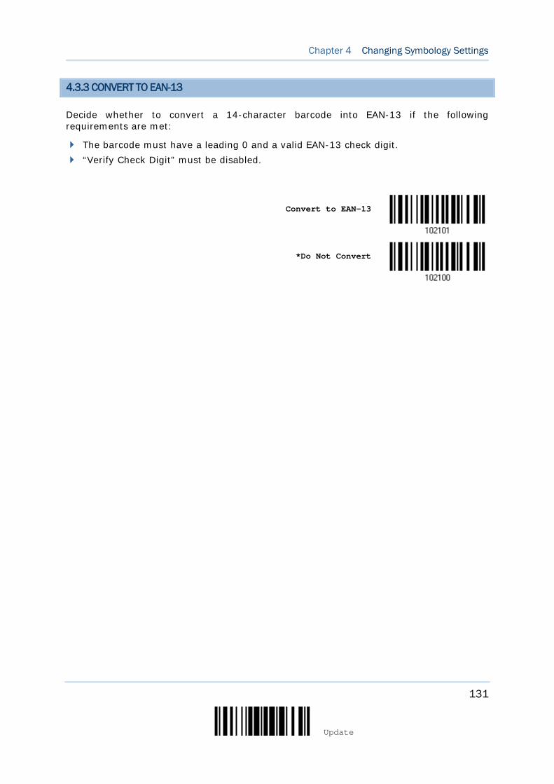
131
Update
Chapter 4 Changing Symbology Settings
4.3.3 CONVERT TO EAN-13
Decide whether to convert a 14-character barcode into EAN-13 if the following requirements are met:
The barcode must have a leading 0 and a valid EAN-13 check digit. “Verify Check Digit” must be disabled.
Convert to EAN-13
*Do Not Convert
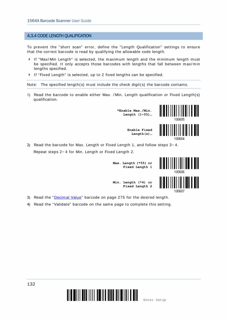
132
Enter Setup
1564A Barcode Scanner User Guide
4.3.4 CODE LENGTH QUALIFICATION
To prevent the "short scan" error, define the "Length Qualification" settings to ensure that the correct barcode is read by qualifying the allowable code length.
If "Max/Min Length" is selected, the maximum length and the minimum length must be specified. It only accepts those barcodes with lengths that fall between max/min lengths specified.
If “Fixed Length” is selected, up to 2 fixed lengths can be specified.
Note: The specified length(s) must include the check digit(s) the barcode contains.
1) Read the barcode to enable either Max. /Min. Length qualification or Fixed Length(s) qualification.
*Enable Max./Min.
Length (1~55)…
Enable Fixed Length(s)…
2) Read the barcode for Max. Length or Fixed Length 1, and follow steps 3~4.
Repeat steps 2~4 for Min. Length or Fixed Length 2.
Max. Length (*55) or Fixed Length 1
Min. Length (*4) or Fixed Length 2
3) Read the “Decimal Value” barcode on page 275 for the desired length.
4) Read the “Validate” barcode on the same page to complete this setting.
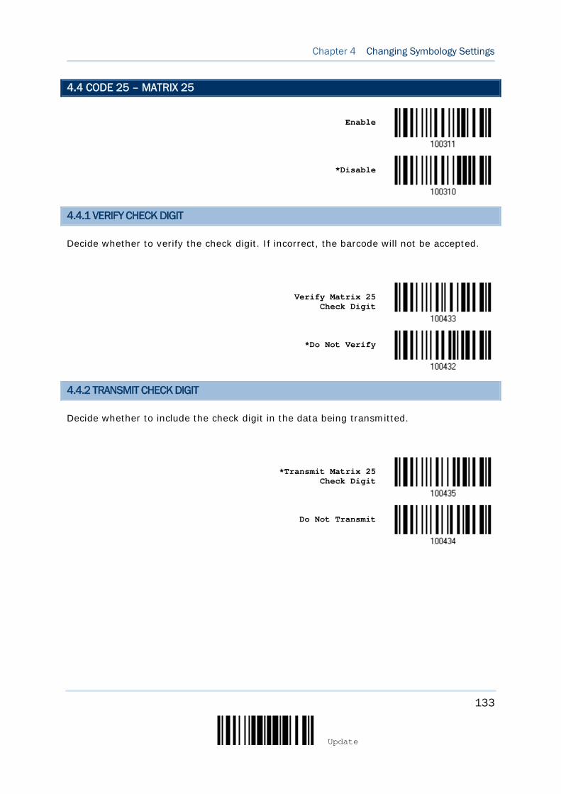
133
Update
Chapter 4 Changing Symbology Settings
4.4 CODE 25 – MATRIX 25
Enable
*Disable
4.4.1 VERIFY CHECK DIGIT
Decide whether to verify the check digit. If incorrect, the barcode will not be accepted.
Verify Matrix 25
Check Digit
*Do Not Verify
4.4.2 TRANSMIT CHECK DIGIT
Decide whether to include the check digit in the data being transmitted.
*Transmit Matrix 25
Check Digit
Do Not Transmit
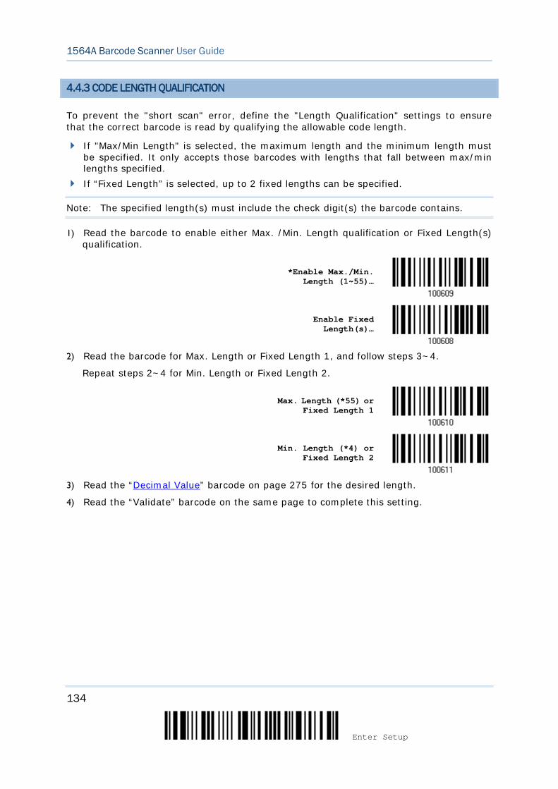
134
Enter Setup
1564A Barcode Scanner User Guide
4.4.3 CODE LENGTH QUALIFICATION
To prevent the "short scan" error, define the "Length Qualification" settings to ensure that the correct barcode is read by qualifying the allowable code length.
If "Max/Min Length" is selected, the maximum length and the minimum length must be specified. It only accepts those barcodes with lengths that fall between max/min lengths specified.
If “Fixed Length” is selected, up to 2 fixed lengths can be specified.
Note: The specified length(s) must include the check digit(s) the barcode contains.
1) Read the barcode to enable either Max. /Min. Length qualification or Fixed Length(s) qualification.
*Enable Max./Min.
Length (1~55)…
Enable Fixed Length(s)…
2) Read the barcode for Max. Length or Fixed Length 1, and follow steps 3~4.
Repeat steps 2~4 for Min. Length or Fixed Length 2.
Max. Length (*55) or Fixed Length 1
Min. Length (*4) or Fixed Length 2
3) Read the “Decimal Value” barcode on page 275 for the desired length.
4) Read the “Validate” barcode on the same page to complete this setting.

135
Update
Chapter 4 Changing Symbology Settings
4.5 CODE 25 – CHINESE 25
Enable
*Disable

136
Enter Setup
1564A Barcode Scanner User Guide
4.6 ITALIAN PHARMACODE (CODE 32)
Enable
*Disable
Note: Code 39 must be enabled first.
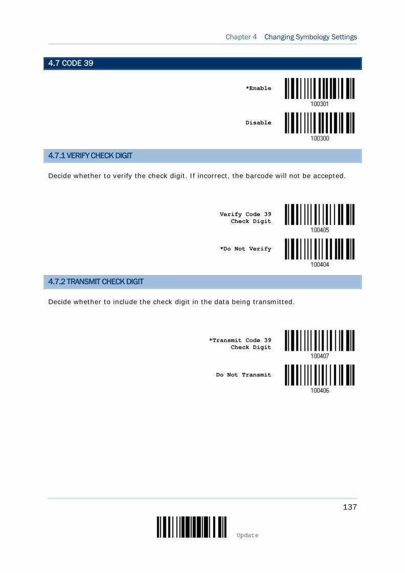
137
Update
Chapter 4 Changing Symbology Settings
4.7 CODE 39
*Enable
Disable
4.7.1 VERIFY CHECK DIGIT
Decide whether to verify the check digit. If incorrect, the barcode will not be accepted.
Verify Code 39
Check Digit
*Do Not Verify
4.7.2 TRANSMIT CHECK DIGIT
Decide whether to include the check digit in the data being transmitted.
*Transmit Code 39
Check Digit
Do Not Transmit

138
Enter Setup
1564A Barcode Scanner User Guide
4.7.3 STANDARD/FULL ASCII CODE 39
Decide whether to support Code 39 Full ASCII that includes all the alphanumeric and special characters.
Code 39 Full ASCII
*Standard Code 39
Note: Trioptic Code 39 and Code 39 Full ASCII cannot be enabled at the same time.
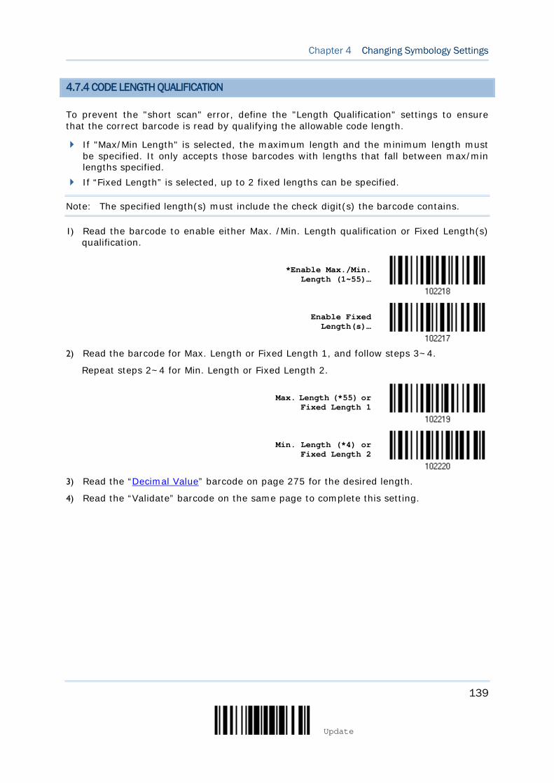
139
Update
Chapter 4 Changing Symbology Settings
4.7.4 CODE LENGTH QUALIFICATION
To prevent the "short scan" error, define the "Length Qualification" settings to ensure that the correct barcode is read by qualifying the allowable code length.
If "Max/Min Length" is selected, the maximum length and the minimum length must be specified. It only accepts those barcodes with lengths that fall between max/min lengths specified.
If “Fixed Length” is selected, up to 2 fixed lengths can be specified.
Note: The specified length(s) must include the check digit(s) the barcode contains.
1) Read the barcode to enable either Max. /Min. Length qualification or Fixed Length(s) qualification.
*Enable Max./Min.
Length (1~55)…
Enable Fixed Length(s)…
2) Read the barcode for Max. Length or Fixed Length 1, and follow steps 3~4.
Repeat steps 2~4 for Min. Length or Fixed Length 2.
Max. Length (*55) or Fixed Length 1
Min. Length (*4) or Fixed Length 2
3) Read the “Decimal Value” barcode on page 275 for the desired length.
4) Read the “Validate” barcode on the same page to complete this setting.
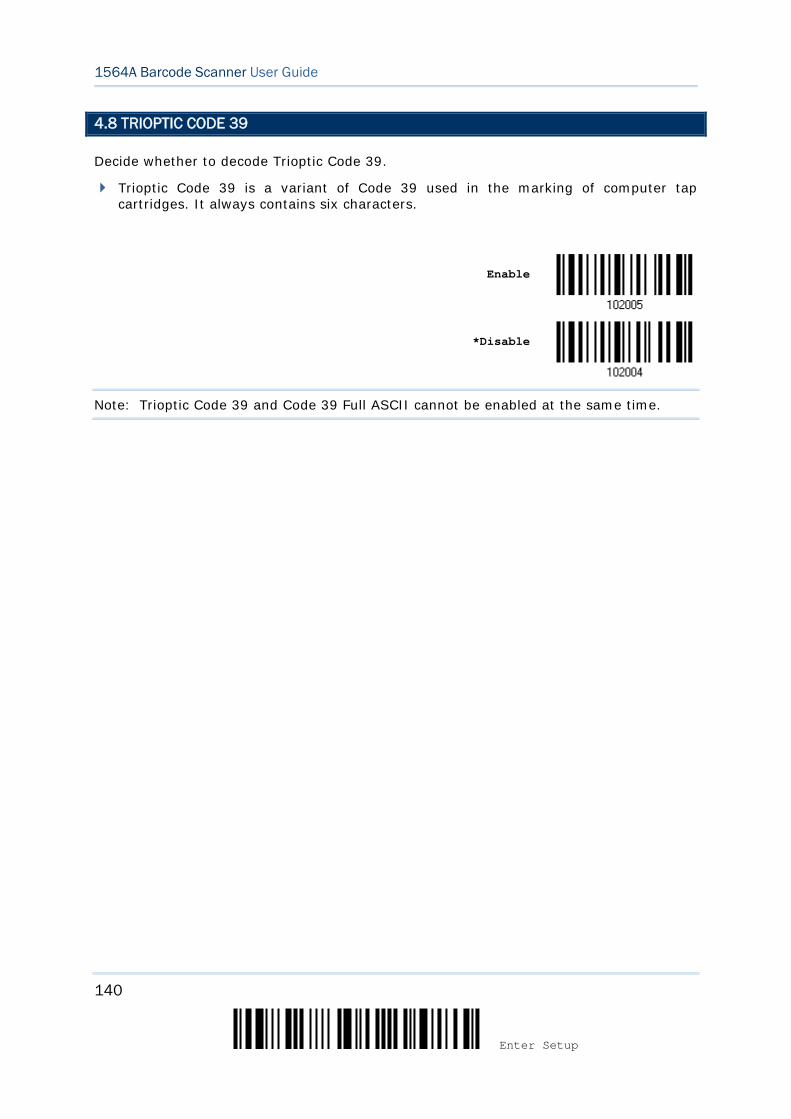
140
Enter Setup
1564A Barcode Scanner User Guide
4.8 TRIOPTIC CODE 39
Decide whether to decode Trioptic Code 39.
Trioptic Code 39 is a variant of Code 39 used in the marking of computer tap cartridges. It always contains six characters.
Enable
*Disable
Note: Trioptic Code 39 and Code 39 Full ASCII cannot be enabled at the same time.
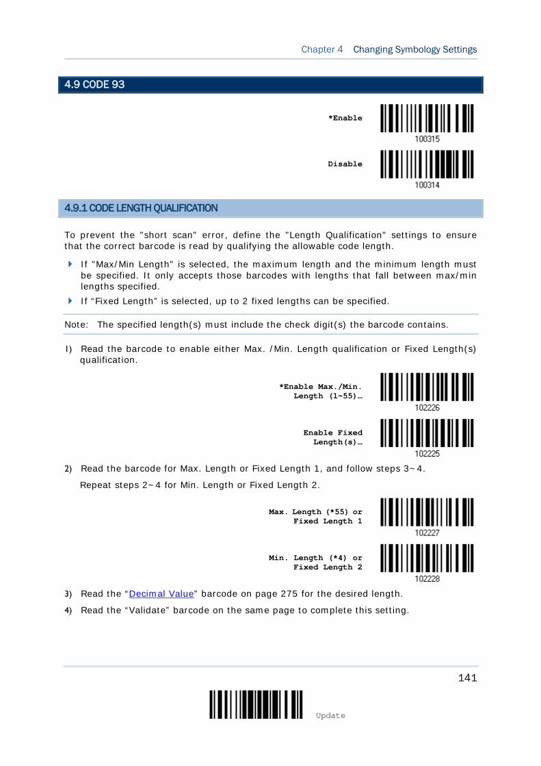
141
Update
Chapter 4 Changing Symbology Settings
4.9 CODE 93
*Enable
Disable
4.9.1 CODE LENGTH QUALIFICATION
To prevent the "short scan" error, define the "Length Qualification" settings to ensure that the correct barcode is read by qualifying the allowable code length.
If "Max/Min Length" is selected, the maximum length and the minimum length must be specified. It only accepts those barcodes with lengths that fall between max/min lengths specified.
If “Fixed Length” is selected, up to 2 fixed lengths can be specified.
Note: The specified length(s) must include the check digit(s) the barcode contains.
1) Read the barcode to enable either Max. /Min. Length qualification or Fixed Length(s) qualification.
*Enable Max./Min.
Length (1~55)…
Enable Fixed Length(s)…
2) Read the barcode for Max. Length or Fixed Length 1, and follow steps 3~4.
Repeat steps 2~4 for Min. Length or Fixed Length 2.
Max. Length (*55) or Fixed Length 1
Min. Length (*4) or Fixed Length 2
3) Read the “Decimal Value” barcode on page 275 for the desired length.
4) Read the “Validate” barcode on the same page to complete this setting.

142
Enter Setup
1564A Barcode Scanner User Guide
4.10 CODE 128
*Enable
Disable
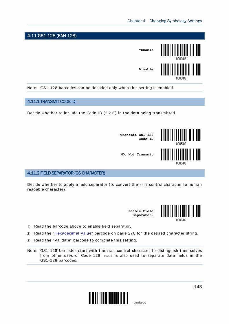
143
Update
Chapter 4 Changing Symbology Settings
4.11 GS1-128 (EAN-128)
*Enable
Disable
Note: GS1-128 barcodes can be decoded only when this setting is enabled.
4.11.1 TRANSMIT CODE ID
Decide whether to include the Code ID (“]C1”) in the data being transmitted.
Transmit GS1-128
Code ID
*Do Not Transmit
4.11.2 FIELD SEPARATOR (GS CHARACTER)
Decide whether to apply a field separator (to convert the FNC1 control character to human readable character).
Enable Field Separator…
1) Read the barcode above to enable field separator.
2) Read the “Hexadecimal Value” barcode on page 276 for the desired character string.
3) Read the “Validate” barcode to complete this setting.
Note: GS1-128 barcodes start with the FNC1 control character to distinguish themselves from other uses of Code 128. FNC1 is also used to separate data fields in the GS1-128 barcodes.
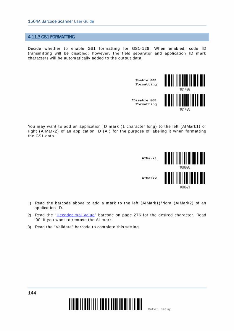
144
Enter Setup
1564A Barcode Scanner User Guide
4.11.3 GS1 FORMATTING
Decide whether to enable GS1 formatting for GS1-128. When enabled, code ID transmitting will be disabled; however, the field separator and application ID mark characters will be automatically added to the output data.
Enable GS1 Formatting
*Disable GS1 Formatting
You may want to add an application ID mark (1 character long) to the left (AIMark1) or right (AIMark2) of an application ID (AI) for the purpose of labeling it when formatting the GS1 data.
AIMark1
AIMark2
1) Read the barcode above to add a mark to the left (AIMark1)/right (AIMark2) of an application ID.
2) Read the “Hexadecimal Value” barcode on page 276 for the desired character. Read '00' if you want to remove the AI mark.
3) Read the “Validate” barcode to complete this setting.
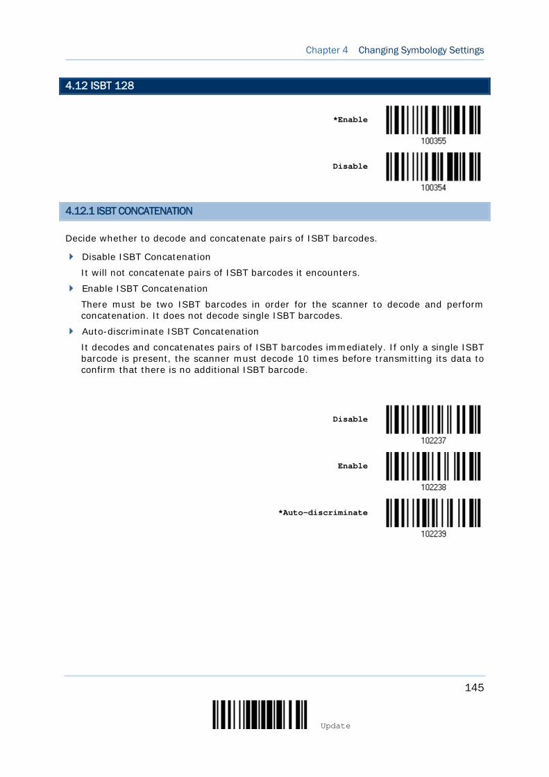
145
Update
Chapter 4 Changing Symbology Settings
4.12 ISBT 128
*Enable
Disable
4.12.1 ISBT CONCATENATION
Decide whether to decode and concatenate pairs of ISBT barcodes.
Disable ISBT Concatenation
It will not concatenate pairs of ISBT barcodes it encounters.
Enable ISBT Concatenation
There must be two ISBT barcodes in order for the scanner to decode and perform concatenation. It does not decode single ISBT barcodes.
Auto-discriminate ISBT Concatenation
It decodes and concatenates pairs of ISBT barcodes immediately. If only a single ISBT barcode is present, the scanner must decode 10 times before transmitting its data to confirm that there is no additional ISBT barcode.
Disable
Enable
*Auto-discriminate
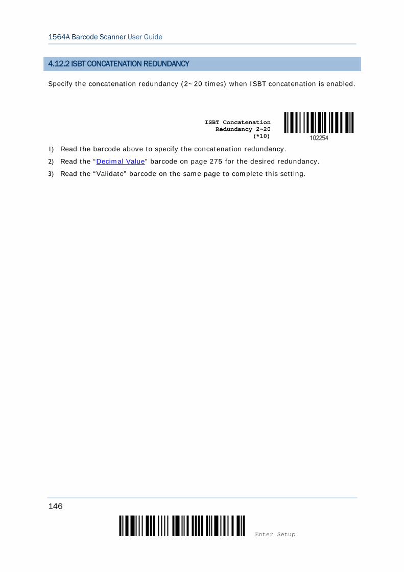
146
Enter Setup
1564A Barcode Scanner User Guide
4.12.2 ISBT CONCATENATION REDUNDANCY
Specify the concatenation redundancy (2~20 times) when ISBT concatenation is enabled.
ISBT Concatenation
Redundancy 2~20 (*10)
1) Read the barcode above to specify the concatenation redundancy.
2) Read the “Decimal Value” barcode on page 275 for the desired redundancy.
3) Read the “Validate” barcode on the same page to complete this setting.
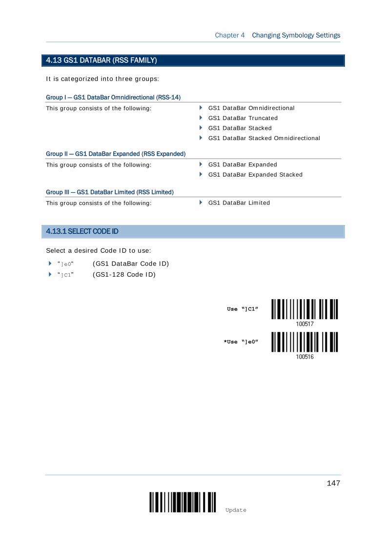
147
Update
Chapter 4 Changing Symbology Settings
4.13 GS1 DATABAR (RSS FAMILY)
It is categorized into three groups:
Group I — GS1 DataBar Omnidirectional (RSS-14)
This group consists of the following:
GS1 DataBar Omnidirectional
GS1 DataBar Truncated
GS1 DataBar Stacked
GS1 DataBar Stacked Omnidirectional
Group II — GS1 DataBar Expanded (RSS Expanded)
This group consists of the following:
GS1 DataBar Expanded
GS1 DataBar Expanded Stacked
Group III — GS1 DataBar Limited (RSS Limited)
This group consists of the following:
GS1 DataBar Limited
4.13.1 SELECT CODE ID
Select a desired Code ID to use:
“]e0“ (GS1 DataBar Code ID) “]C1” (GS1-128 Code ID)
Use “]C1”
*Use “]e0”
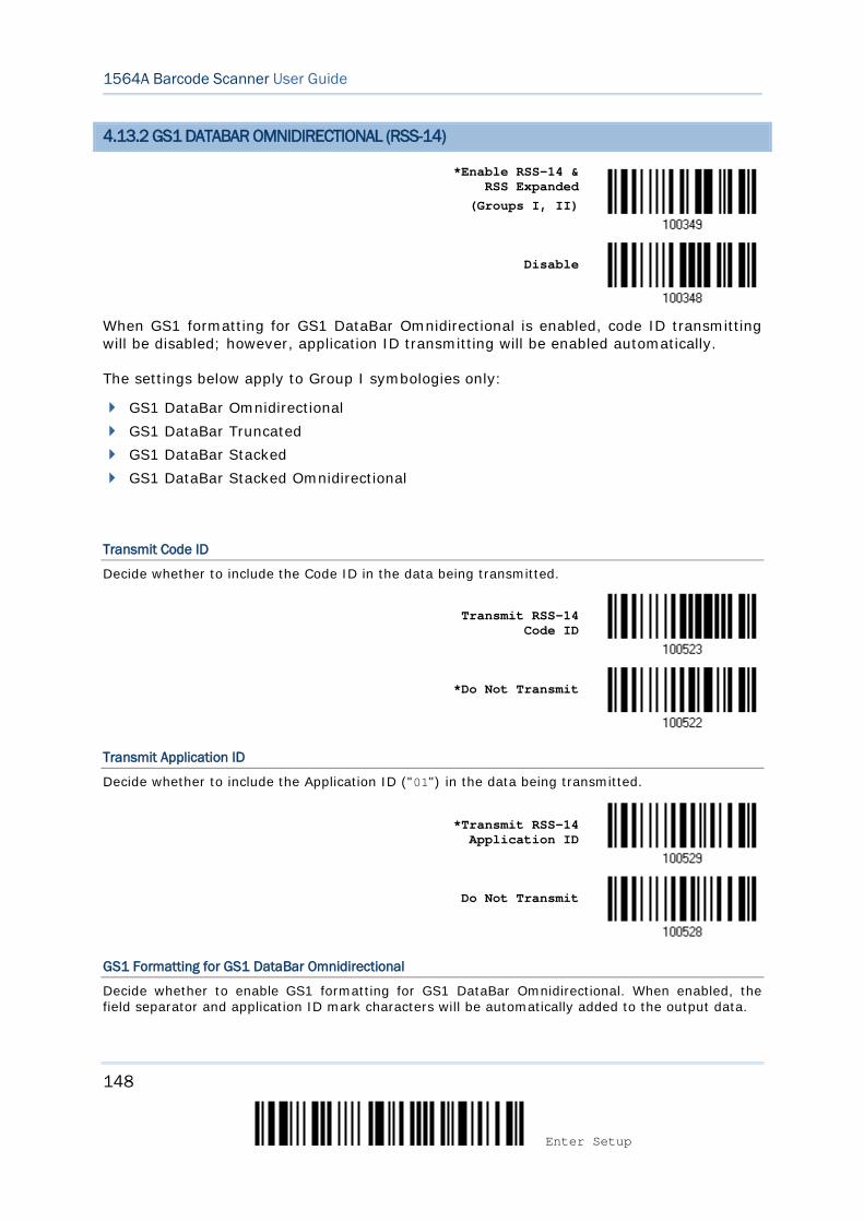
148
Enter Setup
1564A Barcode Scanner User Guide
4.13.2 GS1 DATABAR OMNIDIRECTIONAL (RSS-14)
*Enable RSS-14 & RSS Expanded
(Groups I, II)
Disable
When GS1 formatting for GS1 DataBar Omnidirectional is enabled, code ID transmitting will be disabled; however, application ID transmitting will be enabled automatically.
The settings below apply to Group I symbologies only:
GS1 DataBar Omnidirectional GS1 DataBar Truncated GS1 DataBar Stacked GS1 DataBar Stacked Omnidirectional
Transmit Code ID
Decide whether to include the Code ID in the data being transmitted.
Transmit RSS-14 Code ID
*Do Not Transmit
Transmit Application ID
Decide whether to include the Application ID ("01") in the data being transmitted.
*Transmit RSS-14
Application ID
Do Not Transmit
GS1 Formatting for GS1 DataBar Omnidirectional
Decide whether to enable GS1 formatting for GS1 DataBar Omnidirectional. When enabled, the field separator and application ID mark characters will be automatically added to the output data.
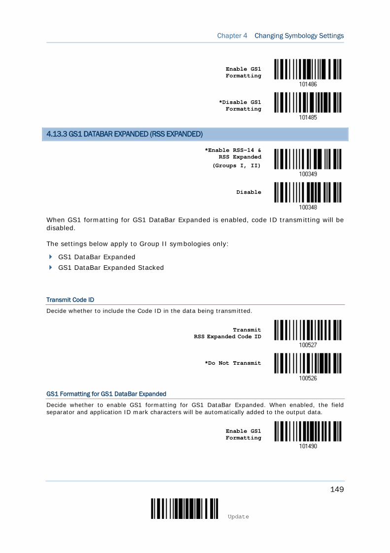
149
Update
Chapter 4 Changing Symbology Settings
Enable GS1 Formatting
*Disable GS1 Formatting
4.13.3 GS1 DATABAR EXPANDED (RSS EXPANDED)
*Enable RSS-14 & RSS Expanded
(Groups I, II)
Disable
When GS1 formatting for GS1 DataBar Expanded is enabled, code ID transmitting will be disabled.
The settings below apply to Group II symbologies only:
GS1 DataBar Expanded GS1 DataBar Expanded Stacked
Transmit Code ID
Decide whether to include the Code ID in the data being transmitted.
Transmit RSS Expanded Code ID
*Do Not Transmit
GS1 Formatting for GS1 DataBar Expanded
Decide whether to enable GS1 formatting for GS1 DataBar Expanded. When enabled, the field separator and application ID mark characters will be automatically added to the output data.
Enable GS1 Formatting
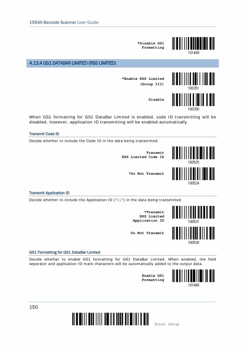
150
Enter Setup
1564A Barcode Scanner User Guide
*Disable GS1 Formatting
4.13.4 GS1 DATABAR LIMITED (RSS LIMITED)
*Enable RSS Limited
(Group III)
Disable
When GS1 formatting for GS1 DataBar Limited is enabled, code ID transmitting will be disabled; however, application ID transmitting will be enabled automatically.
Transmit Code ID
Decide whether to include the Code ID in the data being transmitted.
Transmit RSS Limited Code ID
*Do Not Transmit
Transmit Application ID
Decide whether to include the Application ID ("01") in the data being transmitted.
*Transmit
RSS Limited Application ID
Do Not Transmit
GS1 Formatting for GS1 DataBar Limited
Decide whether to enable GS1 formatting for GS1 DataBar Limited. When enabled, the field separator and application ID mark characters will be automatically added to the output data.
Enable GS1 Formatting
151
Update
Chapter 4 Changing Symbology Settings
*Disable GS1 Formatting
4.13.5 CONVERT TO UPC/EAN
This only applies to GS1 DataBar Omnidirectional and GS1 DataBar Limited barcodes not decoded as part of a Composite barcode.
Convert to EAN-13: It will strip the leading “010” from barcodes.
“01” is the Application ID and must be followed by a single zero (the first digit encoded).
Convert to UPC-A: It will strip the leading “0100” from barcodes.
“01” is the Application ID and must be followed by two or more zeros (but not six zeros).
Convert to UPC/EAN
*Do Not Convert
4.13.6 FIELD SEPARATOR (GS CHARACTER)
Decide whether to apply a field separator (to convert the GS control character to human readable character). The field separator is automatically added to the data when GS1 formatting is enabled.
Specify Field
Separator…
1) Read the barcode above to specify field separator.
2) Read the “Hexadecimal Value” barcode on page 276 for the desired character string.
3) Read the “Validate” barcode to complete this setting.
152
Enter Setup
1564A Barcode Scanner User Guide
4.13.7 APPLICATION ID MARK
You may want to add an application ID mark (1 character long) to the left (AIMark1) or right (AIMark2) of an application ID (AI) for the purpose of labeling it when formatting the GS1 data.
AIMark1
AIMark2
1) Read the barcode above to add a mark to the left (AIMark1)/right (AIMark2) of an
application ID.
2) Read the “Hexadecimal Value” barcode on page 276 for the desired character. Read '00' if you want to remove the AI mark.
3) Read the “Validate” barcode to complete this setting.
153
Update
Chapter 4 Changing Symbology Settings
4.14 MSI
Enable
*Disable
4.14.1 VERIFY CHECK DIGIT
Select one of the three calculations to verify check digit(s) when decoding barcodes. If incorrect, the barcode will not be accepted.
*Single Modulo 10
Double Modulo 10
Modulo 10 & 11
4.14.2 TRANSMIT CHECK DIGIT
Decide whether to include the check digit(s) in the data being transmitted.
*Last Digit Not
Transmitted
Both Digits Transmitted
Both Digits Not Transmitted
154
Enter Setup
1564A Barcode Scanner User Guide
4.14.3 CODE LENGTH QUALIFICATION
To prevent the "short scan" error, define the "Length Qualification" settings to ensure that the correct barcode is read by qualifying the allowable code length.
If "Max/Min Length" is selected, the maximum length and the minimum length must be specified. It only accepts those barcodes with lengths that fall between max/min lengths specified.
If “Fixed Length” is selected, up to 2 fixed lengths can be specified.
Note: The specified length(s) must include the check digit(s) the barcode contains.
1) Read the barcode to enable either Max. /Min. Length qualification or Fixed Length(s) qualification.
*Enable Max./Min.
Length (1~55)…
Enable Fixed Length(s)…
2) Read the barcode for Max. Length or Fixed Length 1, and follow steps 3~4.
Repeat steps 2~4 for Min. Length or Fixed Length 2.
Max. Length (*55) or Fixed Length 1
Min. Length (*4) or Fixed Length 2
3) Read the “Decimal Value” barcode on page 275 for the desired length.
4) Read the “Validate” barcode on the same page to complete this setting.
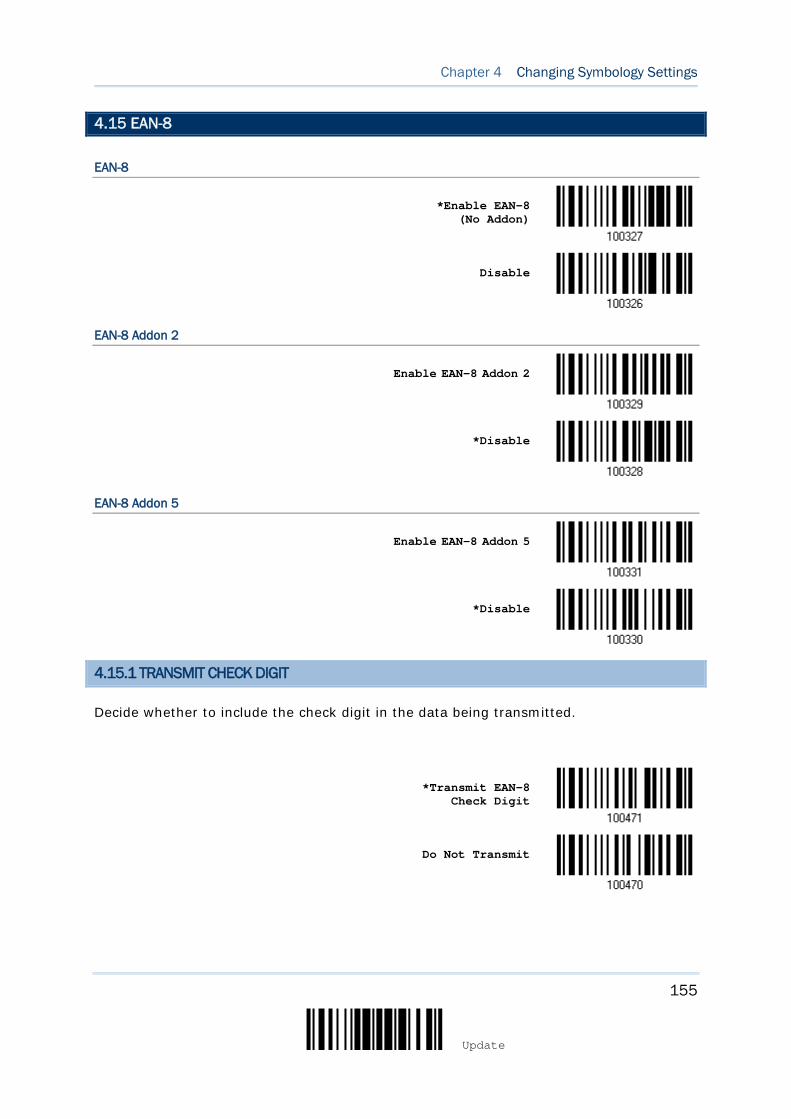
155
Update
Chapter 4 Changing Symbology Settings
4.15 EAN-8
EAN-8
*Enable EAN-8 (No Addon)
Disable
EAN-8 Addon 2
Enable EAN-8 Addon 2
*Disable
EAN-8 Addon 5
Enable EAN-8 Addon 5
*Disable
4.15.1 TRANSMIT CHECK DIGIT
Decide whether to include the check digit in the data being transmitted.
*Transmit EAN-8
Check Digit
Do Not Transmit
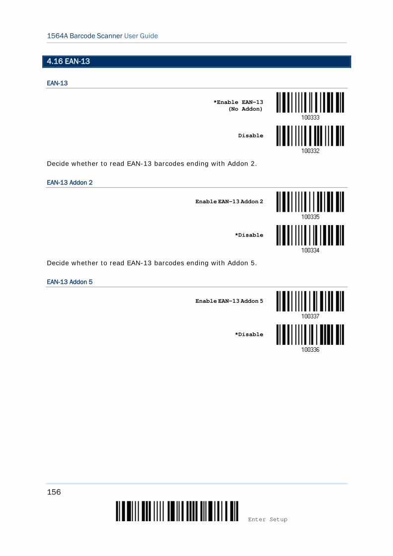
156
Enter Setup
1564A Barcode Scanner User Guide
4.16 EAN-13
EAN-13
*Enable EAN-13 (No Addon)
Disable
Decide whether to read EAN-13 barcodes ending with Addon 2.
EAN-13 Addon 2
Enable EAN-13 Addon 2
*Disable
Decide whether to read EAN-13 barcodes ending with Addon 5.
EAN-13 Addon 5
Enable EAN-13 Addon 5
*Disable
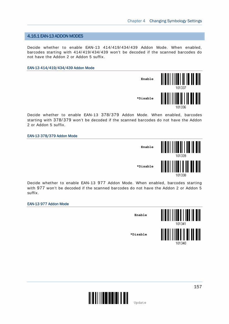
157
Update
Chapter 4 Changing Symbology Settings
4.16.1 EAN-13 ADDON MODES
Decide whether to enable EAN-13 414/419/434/439 Addon Mode. When enabled, barcodes starting with 414/419/434/439 won’t be decoded if the scanned barcodes do not have the Addon 2 or Addon 5 suffix.
EAN-13 414/419/434/439 Addon Mode
Enable
*Disable
Decide whether to enable EAN-13 378/379 Addon Mode. When enabled, barcodes starting with 378/379 won’t be decoded if the scanned barcodes do not have the Addon 2 or Addon 5 suffix.
EAN-13 378/379 Addon Mode
Enable
*Disable
Decide whether to enable EAN-13 977 Addon Mode. When enabled, barcodes starting with 977 won’t be decoded if the scanned barcodes do not have the Addon 2 or Addon 5 suffix.
EAN-13 977 Addon Mode
Enable
*Disable
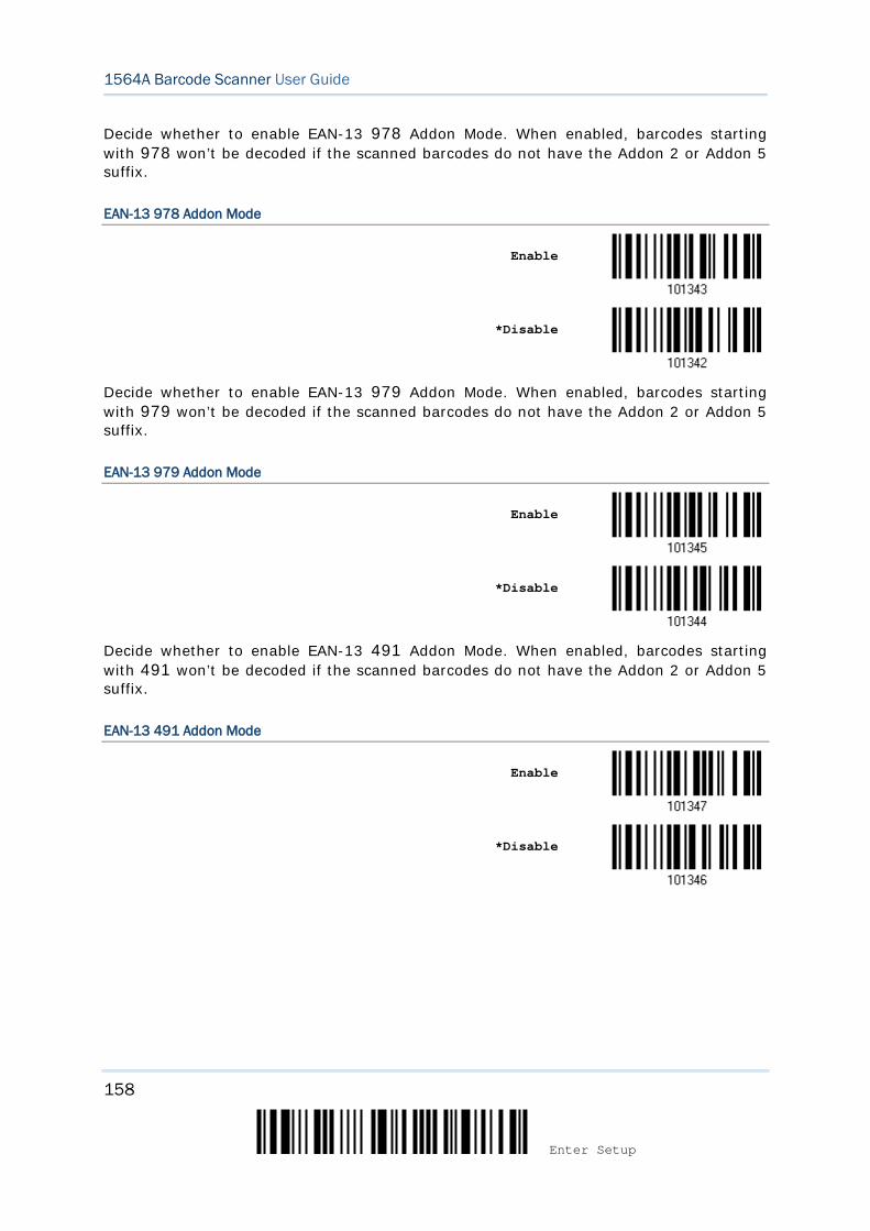
158
Enter Setup
1564A Barcode Scanner User Guide
Decide whether to enable EAN-13 978 Addon Mode. When enabled, barcodes starting with 978 won’t be decoded if the scanned barcodes do not have the Addon 2 or Addon 5 suffix.
EAN-13 978 Addon Mode
Enable
*Disable
Decide whether to enable EAN-13 979 Addon Mode. When enabled, barcodes starting with 979 won’t be decoded if the scanned barcodes do not have the Addon 2 or Addon 5 suffix.
EAN-13 979 Addon Mode
Enable
*Disable
Decide whether to enable EAN-13 491 Addon Mode. When enabled, barcodes starting with 491 won’t be decoded if the scanned barcodes do not have the Addon 2 or Addon 5 suffix.
EAN-13 491 Addon Mode
Enable
*Disable
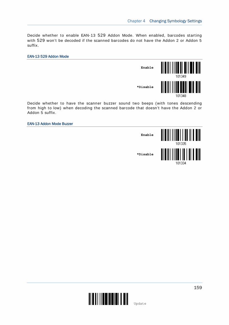
159
Update
Chapter 4 Changing Symbology Settings
Decide whether to enable EAN-13 529 Addon Mode. When enabled, barcodes starting with 529 won’t be decoded if the scanned barcodes do not have the Addon 2 or Addon 5 suffix.
EAN-13 529 Addon Mode
Enable
*Disable
Decide whether to have the scanner buzzer sound two beeps (with tones descending from high to low) when decoding the scanned barcode that doesn’t have the Addon 2 or Addon 5 suffix.
EAN-13 Addon Mode Buzzer
Enable
*Disable
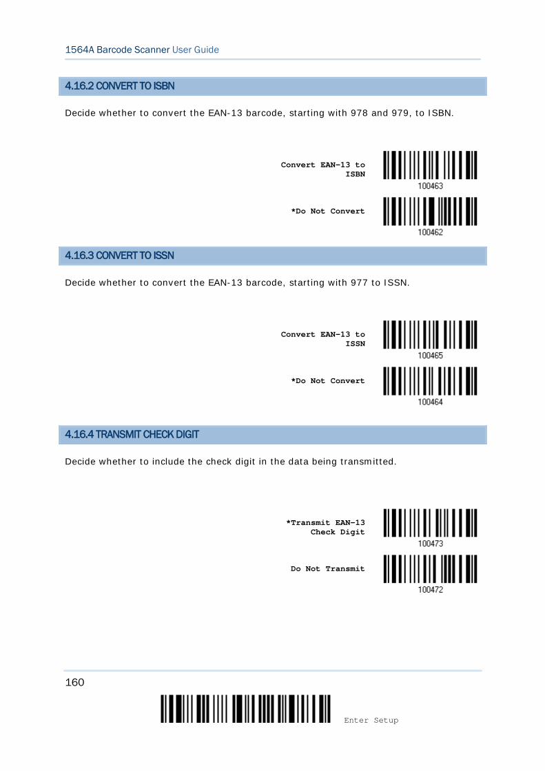
160
Enter Setup
1564A Barcode Scanner User Guide
4.16.2 CONVERT TO ISBN
Decide whether to convert the EAN-13 barcode, starting with 978 and 979, to ISBN.
Convert EAN-13 to
ISBN
*Do Not Convert
4.16.3 CONVERT TO ISSN
Decide whether to convert the EAN-13 barcode, starting with 977 to ISSN.
Convert EAN-13 to
ISSN
*Do Not Convert
4.16.4 TRANSMIT CHECK DIGIT
Decide whether to include the check digit in the data being transmitted.
*Transmit EAN-13
Check Digit
Do Not Transmit
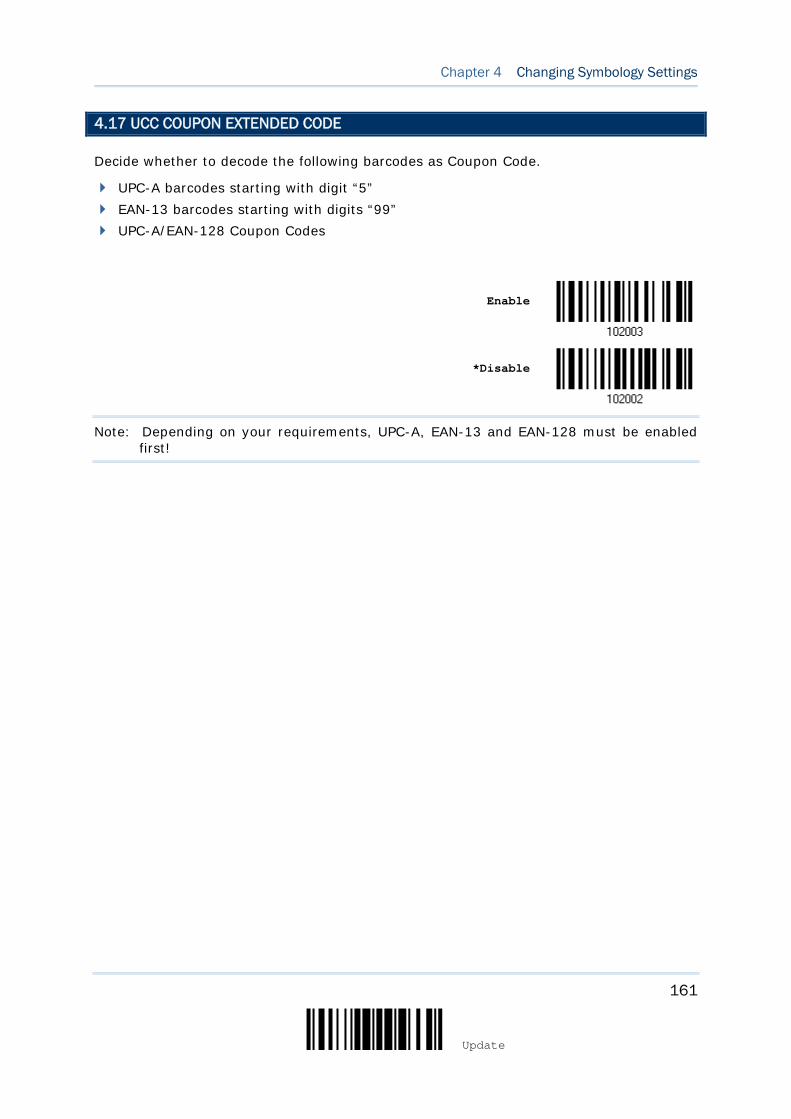
161
Update
Chapter 4 Changing Symbology Settings
4.17 UCC COUPON EXTENDED CODE
Decide whether to decode the following barcodes as Coupon Code.
UPC-A barcodes starting with digit “5” EAN-13 barcodes starting with digits “99” UPC-A/EAN-128 Coupon Codes
Enable
*Disable
Note: Depending on your requirements, UPC-A, EAN-13 and EAN-128 must be enabled first!
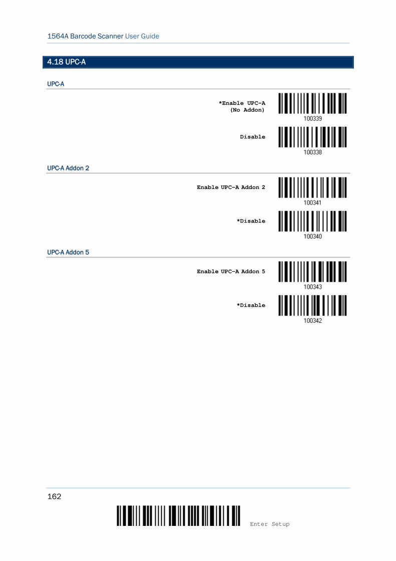
162
Enter Setup
1564A Barcode Scanner User Guide
4.18 UPC-A
UPC-A
*Enable UPC-A (No Addon)
Disable
UPC-A Addon 2
Enable UPC-A Addon 2
*Disable
UPC-A Addon 5
Enable UPC-A Addon 5
*Disable
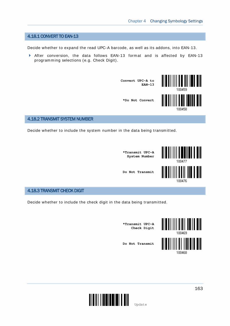
163
Update
Chapter 4 Changing Symbology Settings
4.18.1 CONVERT TO EAN-13
Decide whether to expand the read UPC-A barcode, as well as its addons, into EAN-13.
After conversion, the data follows EAN-13 format and is affected by EAN-13 programming selections (e.g. Check Digit).
Convert UPC-A to EAN-13
*Do Not Convert
4.18.2 TRANSMIT SYSTEM NUMBER
Decide whether to include the system number in the data being transmitted.
*Transmit UPC-A
System Number
Do Not Transmit
4.18.3 TRANSMIT CHECK DIGIT
Decide whether to include the check digit in the data being transmitted.
*Transmit UPC-A
Check Digit
Do Not Transmit
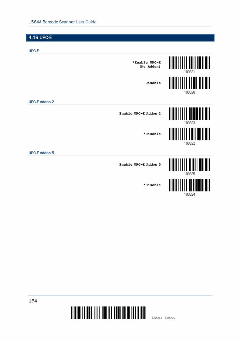
164
Enter Setup
1564A Barcode Scanner User Guide
4.19 UPC-E
UPC-E
*Enable UPC-E (No Addon)
Disable
UPC-E Addon 2
Enable UPC-E Addon 2
*Disable
UPC-E Addon 5
Enable UPC-E Addon 5
*Disable
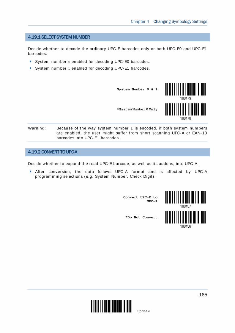
165
Update
Chapter 4 Changing Symbology Settings
4.19.1 SELECT SYSTEM NUMBER
Decide whether to decode the ordinary UPC-E barcodes only or both UPC-E0 and UPC-E1 barcodes.
System number 0 enabled for decoding UPC-E0 barcodes. System number 1 enabled for decoding UPC-E1 barcodes.
System Number 0 & 1
*System Number 0 Only
Warning: Because of the way system number 1 is encoded, if both system numbers are enabled, the user might suffer from short scanning UPC-A or EAN-13 barcodes into UPC-E1 barcodes.
4.19.2 CONVERT TO UPC-A
Decide whether to expand the read UPC-E barcode, as well as its addons, into UPC-A.
After conversion, the data follows UPC-A format and is affected by UPC-A programming selections (e.g. System Number, Check Digit).
Convert UPC-E to
UPC-A
*Do Not Convert
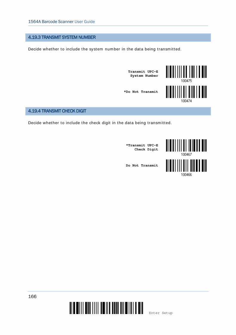
166
Enter Setup
1564A Barcode Scanner User Guide
4.19.3 TRANSMIT SYSTEM NUMBER
Decide whether to include the system number in the data being transmitted.
Transmit UPC-E System Number
*Do Not Transmit
4.19.4 TRANSMIT CHECK DIGIT
Decide whether to include the check digit in the data being transmitted.
*Transmit UPC-E
Check Digit
Do Not Transmit
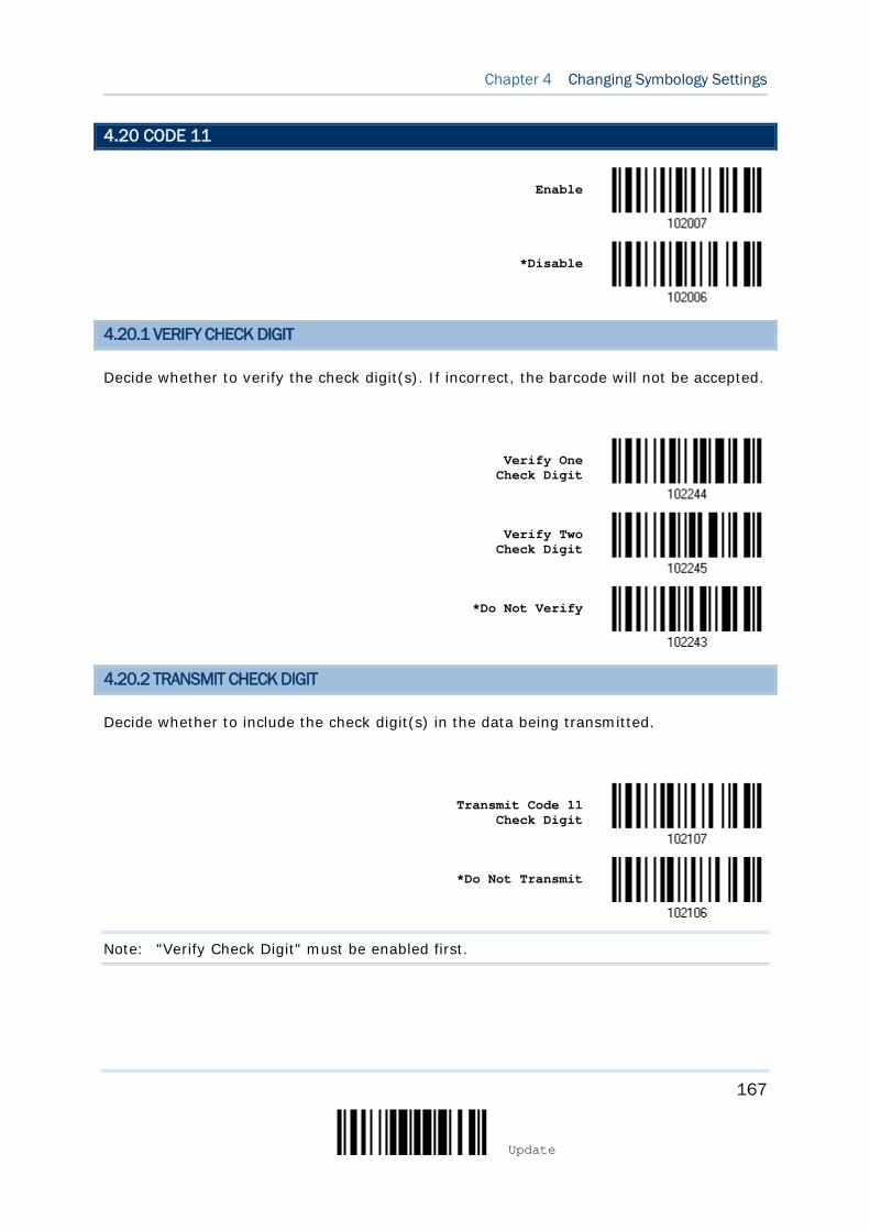
167
Update
Chapter 4 Changing Symbology Settings
4.20 CODE 11
Enable
*Disable
4.20.1 VERIFY CHECK DIGIT
Decide whether to verify the check digit(s). If incorrect, the barcode will not be accepted.
Verify One Check Digit
Verify Two Check Digit
*Do Not Verify
4.20.2 TRANSMIT CHECK DIGIT
Decide whether to include the check digit(s) in the data being transmitted.
Transmit Code 11
Check Digit
*Do Not Transmit
Note: "Verify Check Digit" must be enabled first.
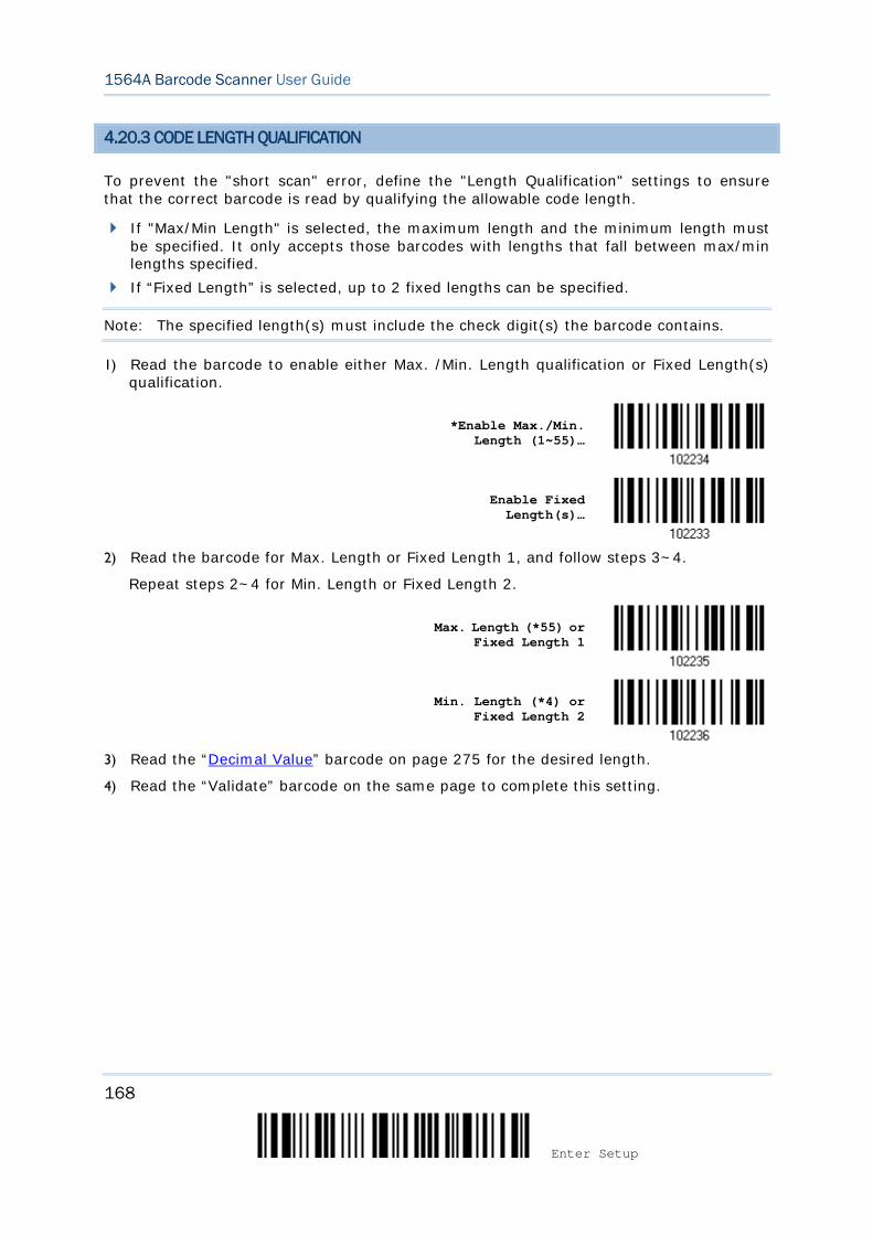
168
Enter Setup
1564A Barcode Scanner User Guide
4.20.3 CODE LENGTH QUALIFICATION
To prevent the "short scan" error, define the "Length Qualification" settings to ensure that the correct barcode is read by qualifying the allowable code length.
If "Max/Min Length" is selected, the maximum length and the minimum length must be specified. It only accepts those barcodes with lengths that fall between max/min lengths specified.
If “Fixed Length” is selected, up to 2 fixed lengths can be specified.
Note: The specified length(s) must include the check digit(s) the barcode contains.
1) Read the barcode to enable either Max. /Min. Length qualification or Fixed Length(s) qualification.
*Enable Max./Min.
Length (1~55)…
Enable Fixed Length(s)…
2) Read the barcode for Max. Length or Fixed Length 1, and follow steps 3~4.
Repeat steps 2~4 for Min. Length or Fixed Length 2.
Max. Length (*55) or Fixed Length 1
Min. Length (*4) or Fixed Length 2
3) Read the “Decimal Value” barcode on page 275 for the desired length.
4) Read the “Validate” barcode on the same page to complete this setting.
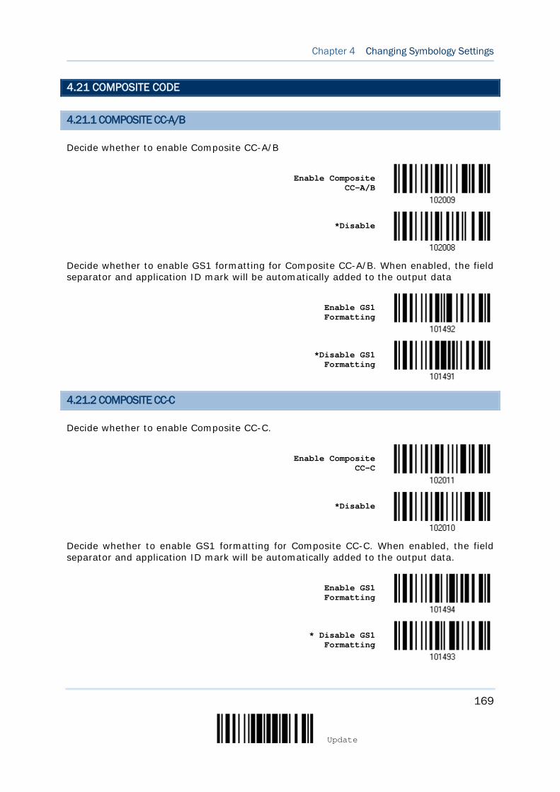
169
Update
Chapter 4 Changing Symbology Settings
4.21 COMPOSITE CODE
4.21.1 COMPOSITE CC-A/B
Decide whether to enable Composite CC-A/B
Enable Composite
CC-A/B
*Disable
Decide whether to enable GS1 formatting for Composite CC-A/B. When enabled, the field separator and application ID mark will be automatically added to the output data
Enable GS1 Formatting
*Disable GS1 Formatting
4.21.2 COMPOSITE CC-C
Decide whether to enable Composite CC-C.
Enable Composite
CC-C
*Disable
Decide whether to enable GS1 formatting for Composite CC-C. When enabled, the field separator and application ID mark will be automatically added to the output data.
Enable GS1 Formatting
* Disable GS1 Formatting

170
Enter Setup
1564A Barcode Scanner User Guide
4.21.3 COMPOSITE TLC-39
Enable Composite
TLC-39
*Disable
4.21.4 UPC COMPOSITE MODE
UPC barcodes can be “linked” with a 2D barcode during transmission as if they were one barcode.
UPC Never Linked
Transmit UPC barcodes regardless of whether a 2D barcode is detected.
UPC Always Linked
Transmit UPC barcodes and the 2D portion. If the 2D portion is not detected, the UPC barcode will not be transmitted.
Note: CC-A/B or CC-C must be enabled!
Auto-discriminate UPC Composites
Transmit UPC barcodes as well as the 2D portion if present.
UPC Never Linked
*UPC Always Linked
Auto-discriminate
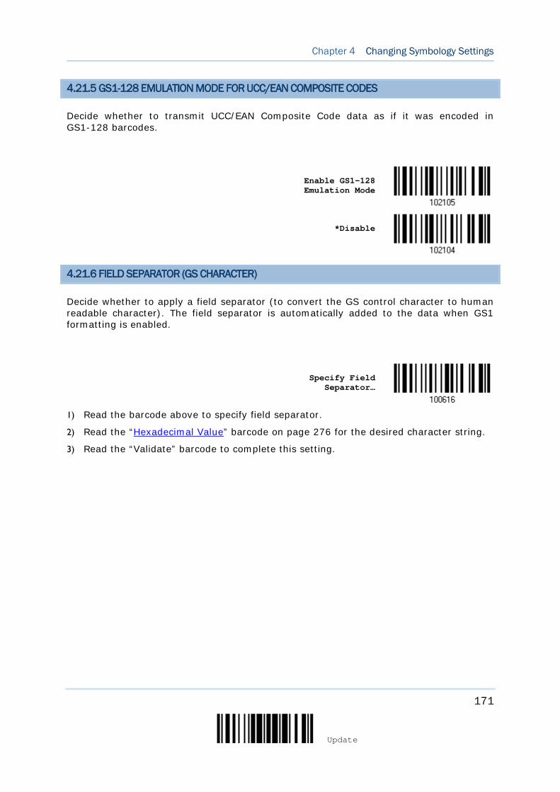
171
Update
Chapter 4 Changing Symbology Settings
4.21.5 GS1-128 EMULATION MODE FOR UCC/EAN COMPOSITE CODES
Decide whether to transmit UCC/EAN Composite Code data as if it was encoded in GS1-128 barcodes.
Enable GS1-128 Emulation Mode
*Disable
4.21.6 FIELD SEPARATOR (GS CHARACTER)
Decide whether to apply a field separator (to convert the GS control character to human readable character). The field separator is automatically added to the data when GS1 formatting is enabled.
Specify Field
Separator…
1) Read the barcode above to specify field separator.
2) Read the “Hexadecimal Value” barcode on page 276 for the desired character string.
3) Read the “Validate” barcode to complete this setting.
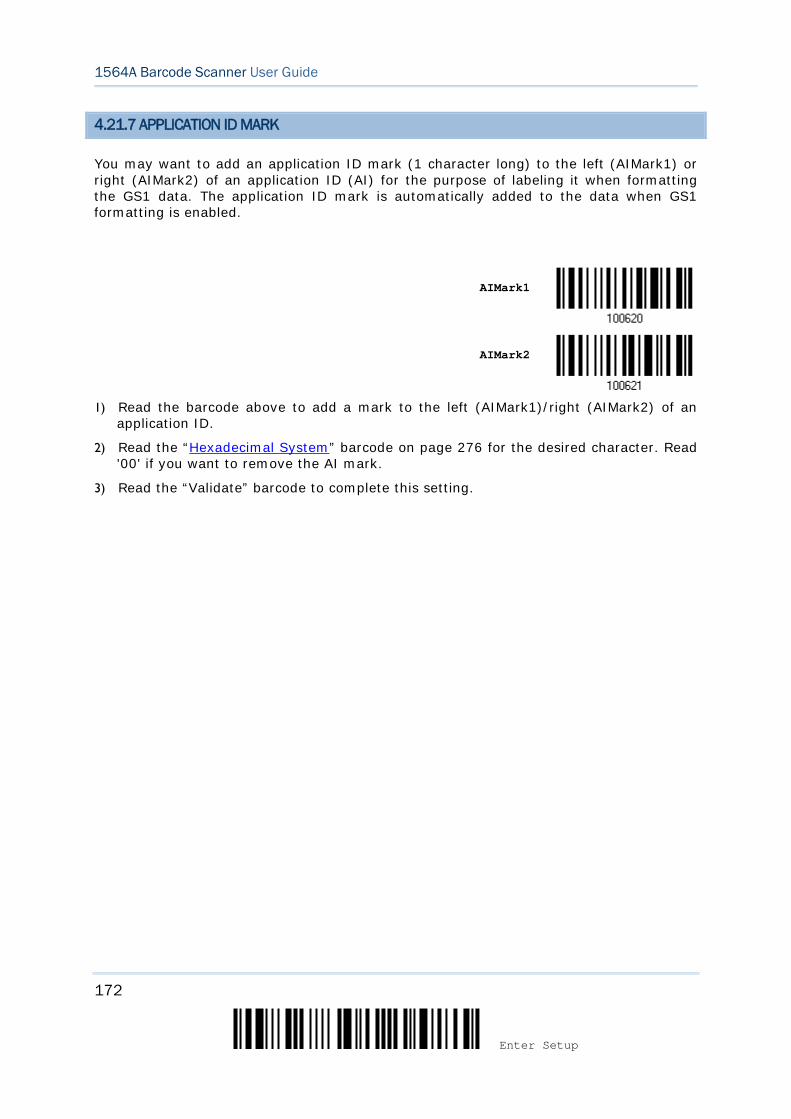
172
Enter Setup
1564A Barcode Scanner User Guide
4.21.7 APPLICATION ID MARK
You may want to add an application ID mark (1 character long) to the left (AIMark1) or right (AIMark2) of an application ID (AI) for the purpose of labeling it when formatting the GS1 data. The application ID mark is automatically added to the data when GS1 formatting is enabled.
AIMark1
AIMark2
1) Read the barcode above to add a mark to the left (AIMark1)/right (AIMark2) of an
application ID.
2) Read the “Hexadecimal System” barcode on page 276 for the desired character. Read '00' if you want to remove the AI mark.
3) Read the “Validate” barcode to complete this setting.
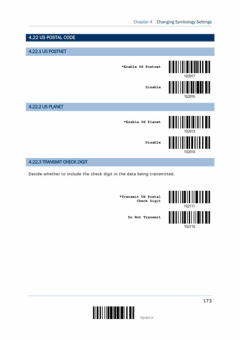
173
Update
Chapter 4 Changing Symbology Settings
4.22 US POSTAL CODE
4.22.1 US POSTNET
*Enable US Postnet
Disable
4.22.2 US PLANET
*Enable US Planet
Disable
4.22.3 TRANSMIT CHECK DIGIT
Decide whether to include the check digit in the data being transmitted.
*Transmit US Postal
Check Digit
Do Not Transmit
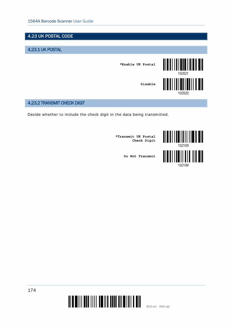
174
Enter Setup
1564A Barcode Scanner User Guide
4.23 UK POSTAL CODE
4.23.1 UK POSTAL
*Enable UK Postal
Disable
4.23.2 TRANSMIT CHECK DIGIT
Decide whether to include the check digit in the data being transmitted.
*Transmit UK Postal
Check Digit
Do Not Transmit
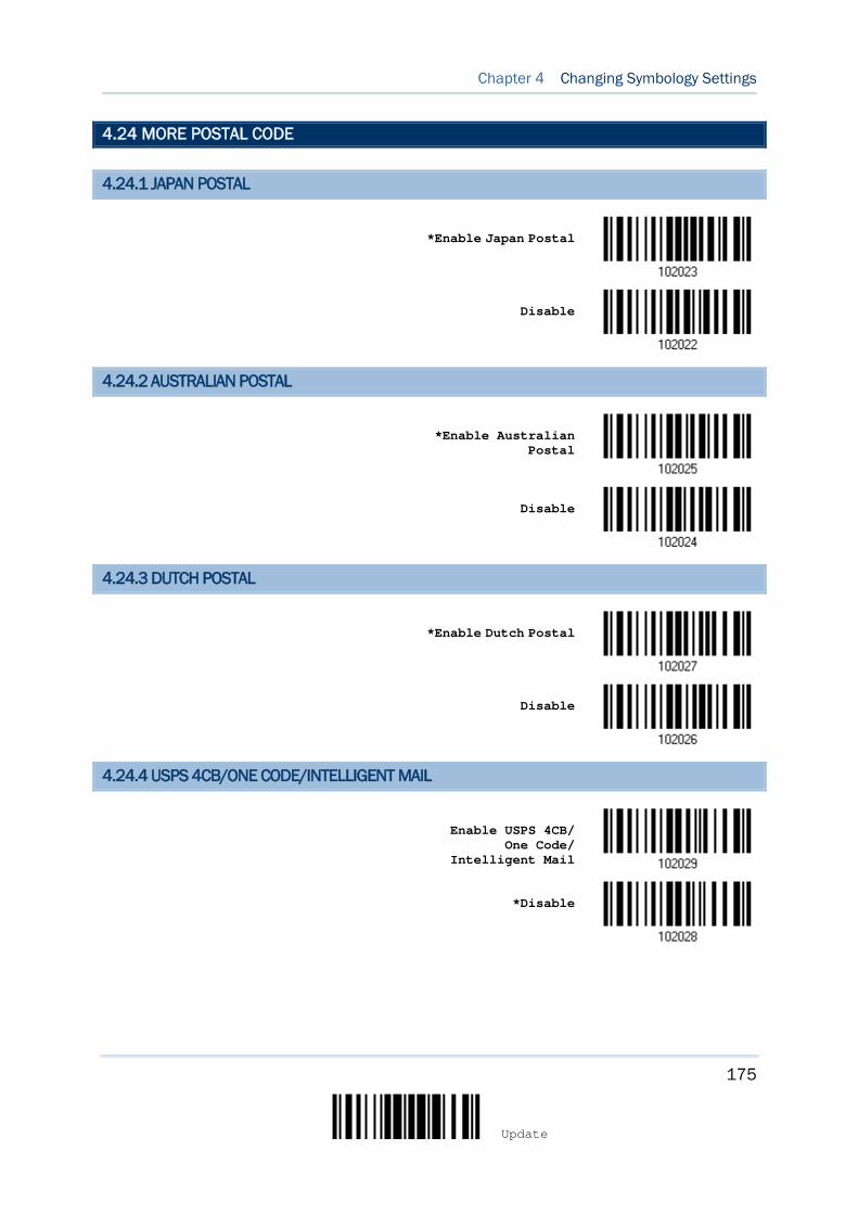
175
Update
Chapter 4 Changing Symbology Settings
4.24 MORE POSTAL CODE
4.24.1 JAPAN POSTAL
*Enable Japan Postal
Disable
4.24.2 AUSTRALIAN POSTAL
*Enable Australian
Postal
Disable
4.24.3 DUTCH POSTAL
*Enable Dutch Postal
Disable
4.24.4 USPS 4CB/ONE CODE/INTELLIGENT MAIL
Enable USPS 4CB/
One Code/ Intelligent Mail
*Disable
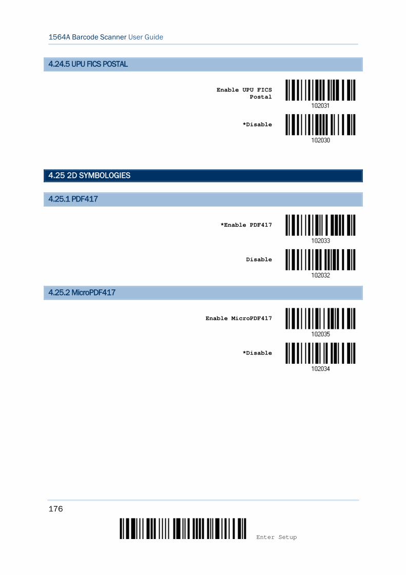
176
Enter Setup
1564A Barcode Scanner User Guide
4.24.5 UPU FICS POSTAL
Enable UPU FICS
Postal
*Disable
4.25 2D SYMBOLOGIES
4.25.1 PDF417
*Enable PDF417
Disable
4.25.2 MicroPDF417
Enable MicroPDF417
*Disable
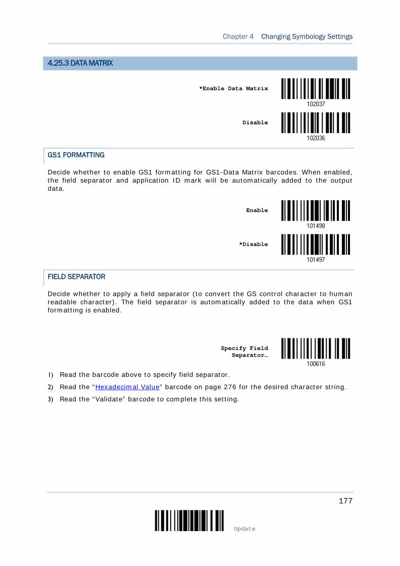
177
Update
Chapter 4 Changing Symbology Settings
4.25.3 DATA MATRIX
*Enable Data Matrix
Disable
GS1 FORMATTING
Decide whether to enable GS1 formatting for GS1-Data Matrix barcodes. When enabled, the field separator and application ID mark will be automatically added to the output data.
Enable
*Disable
FIELD SEPARATOR
Decide whether to apply a field separator (to convert the GS control character to human readable character). The field separator is automatically added to the data when GS1 formatting is enabled.
Specify Field
Separator…
1) Read the barcode above to specify field separator.
2) Read the “Hexadecimal Value” barcode on page 276 for the desired character string.
3) Read the “Validate” barcode to complete this setting.
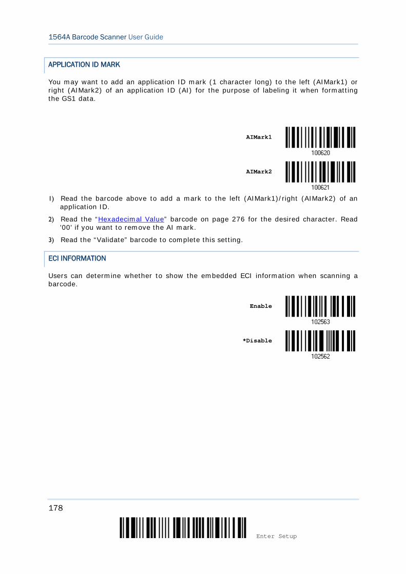
178
Enter Setup
1564A Barcode Scanner User Guide
APPLICATION ID MARK
You may want to add an application ID mark (1 character long) to the left (AIMark1) or right (AIMark2) of an application ID (AI) for the purpose of labeling it when formatting the GS1 data.
AIMark1
AIMark2
1) Read the barcode above to add a mark to the left (AIMark1)/right (AIMark2) of an
application ID.
2) Read the “Hexadecimal Value” barcode on page 276 for the desired character. Read '00' if you want to remove the AI mark.
3) Read the “Validate” barcode to complete this setting.
ECI INFORMATION
Users can determine whether to show the embedded ECI information when scanning a barcode.
Enable
*Disable
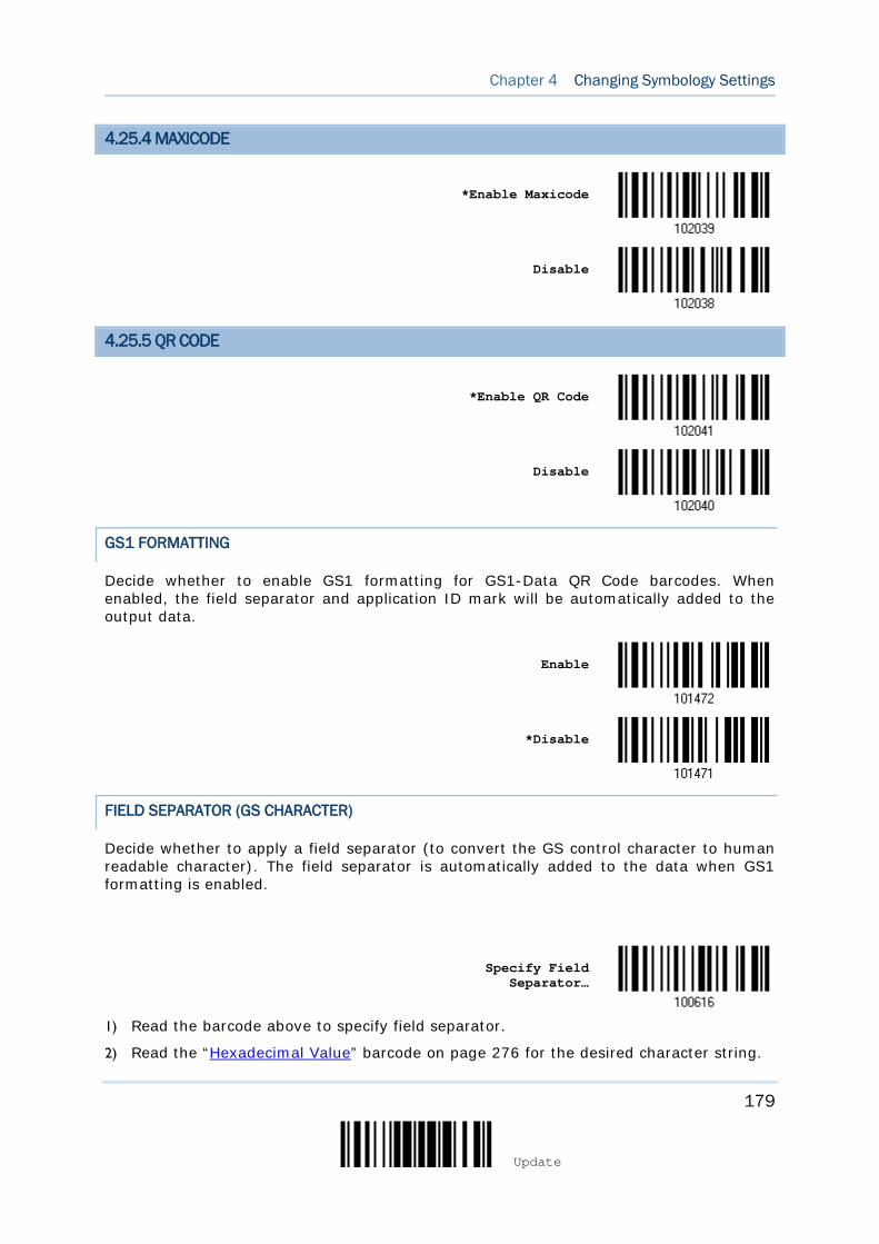
179
Update
Chapter 4 Changing Symbology Settings
4.25.4 MAXICODE
*Enable Maxicode
Disable
4.25.5 QR CODE
*Enable QR Code
Disable
GS1 FORMATTING
Decide whether to enable GS1 formatting for GS1-Data QR Code barcodes. When enabled, the field separator and application ID mark will be automatically added to the output data.
Enable
*Disable
FIELD SEPARATOR (GS CHARACTER)
Decide whether to apply a field separator (to convert the GS control character to human readable character). The field separator is automatically added to the data when GS1 formatting is enabled.
Specify Field
Separator…
1) Read the barcode above to specify field separator.
2) Read the “Hexadecimal Value” barcode on page 276 for the desired character string.
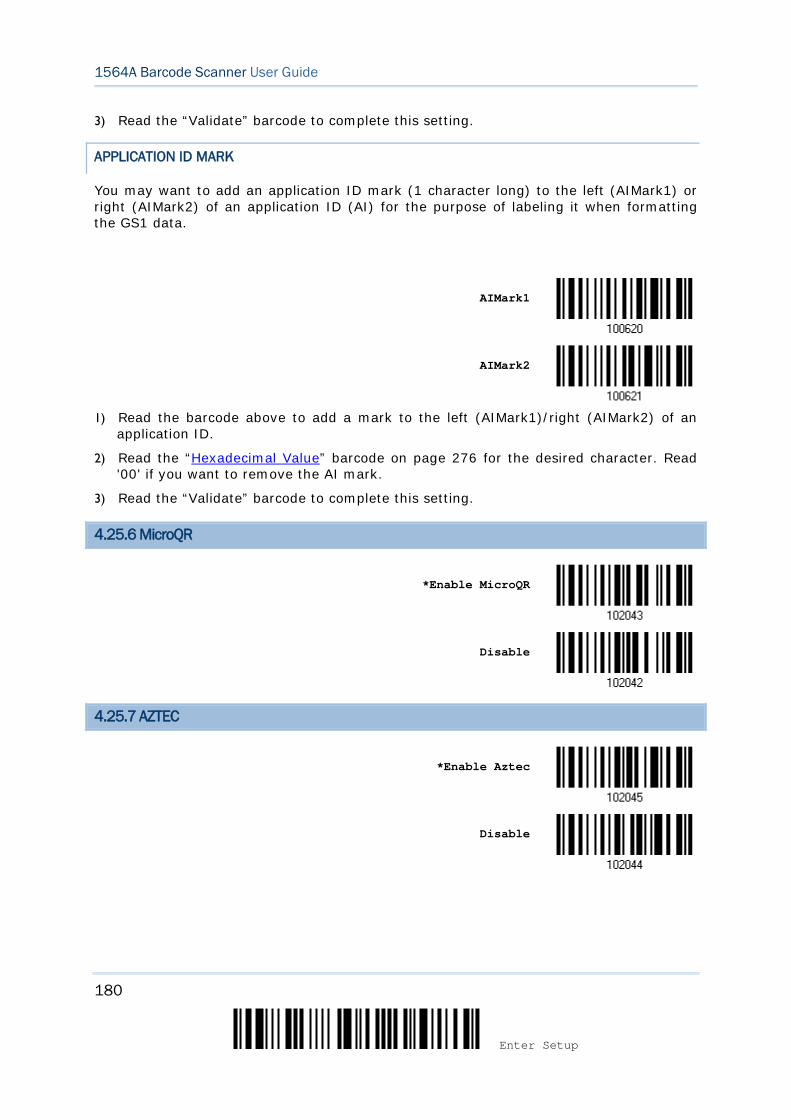
180
Enter Setup
1564A Barcode Scanner User Guide
3) Read the “Validate” barcode to complete this setting.
APPLICATION ID MARK
You may want to add an application ID mark (1 character long) to the left (AIMark1) or right (AIMark2) of an application ID (AI) for the purpose of labeling it when formatting the GS1 data.
AIMark1
AIMark2
1) Read the barcode above to add a mark to the left (AIMark1)/right (AIMark2) of an
application ID.
2) Read the “Hexadecimal Value” barcode on page 276 for the desired character. Read '00' if you want to remove the AI mark.
3) Read the “Validate” barcode to complete this setting.
4.25.6 MicroQR
*Enable MicroQR
Disable
4.25.7 AZTEC
*Enable Aztec
Disable
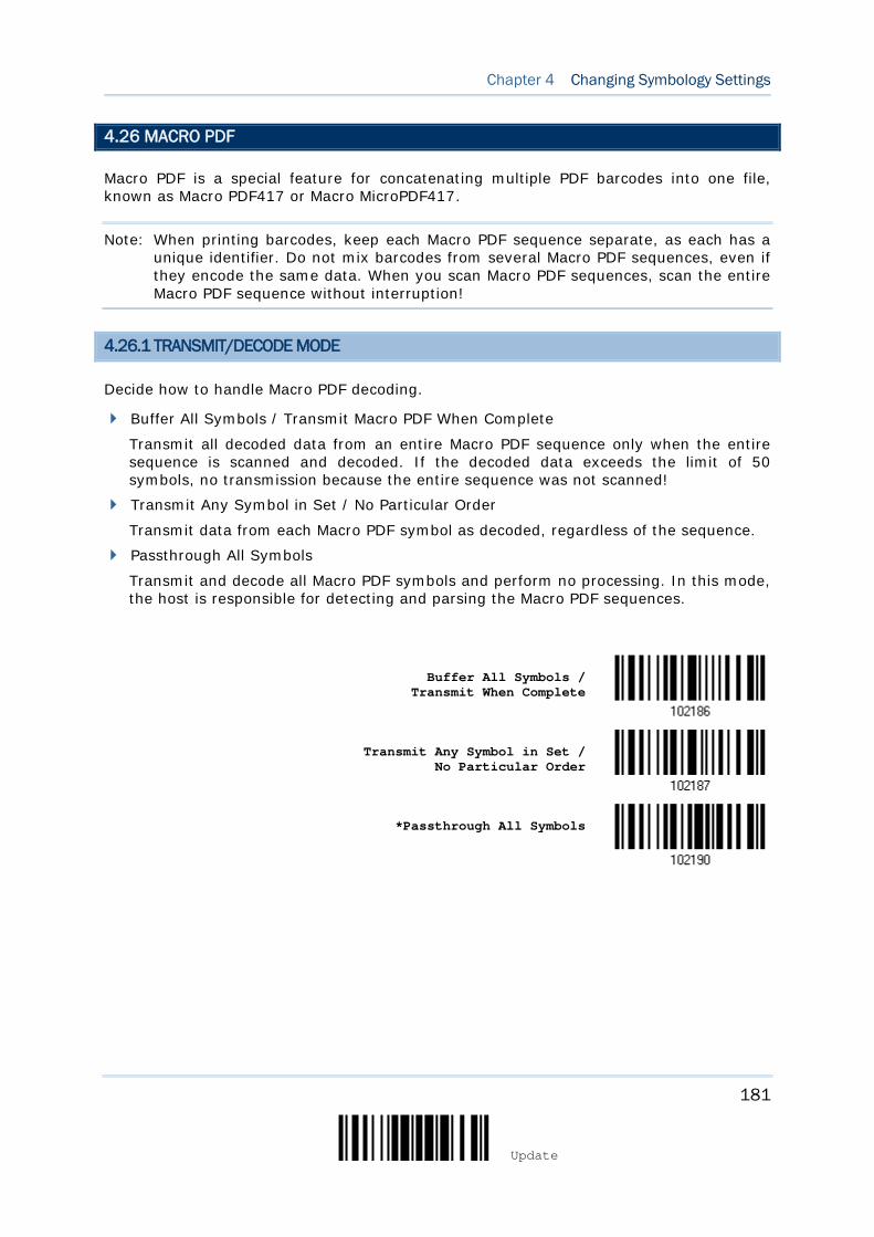
181
Update
Chapter 4 Changing Symbology Settings
4.26 MACRO PDF
Macro PDF is a special feature for concatenating multiple PDF barcodes into one file, known as Macro PDF417 or Macro MicroPDF417.
Note: When printing barcodes, keep each Macro PDF sequence separate, as each has a unique identifier. Do not mix barcodes from several Macro PDF sequences, even if they encode the same data. When you scan Macro PDF sequences, scan the entire Macro PDF sequence without interruption!
4.26.1 TRANSMIT/DECODE MODE
Decide how to handle Macro PDF decoding.
Buffer All Symbols / Transmit Macro PDF When Complete
Transmit all decoded data from an entire Macro PDF sequence only when the entire sequence is scanned and decoded. If the decoded data exceeds the limit of 50 symbols, no transmission because the entire sequence was not scanned!
Transmit Any Symbol in Set / No Particular Order
Transmit data from each Macro PDF symbol as decoded, regardless of the sequence.
Passthrough All Symbols
Transmit and decode all Macro PDF symbols and perform no processing. In this mode, the host is responsible for detecting and parsing the Macro PDF sequences.
Buffer All Symbols /
Transmit When Complete
Transmit Any Symbol in Set / No Particular Order
*Passthrough All Symbols
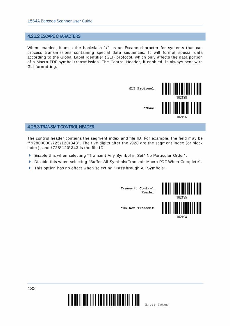
182
Enter Setup
1564A Barcode Scanner User Guide
4.26.2 ESCAPE CHARACTERS
When enabled, it uses the backslash "\" as an Escape character for systems that can process transmissions containing special data sequences. It will format special data according to the Global Label Identifier (GLI) protocol, which only affects the data portion of a Macro PDF symbol transmission. The Control Header, if enabled, is always sent with GLI formatting.
GLI Protocol
*None
4.26.3 TRANSMIT CONTROL HEADER
The control header contains the segment index and file ID. For example, the field may be “\92800000\725\120\343”. The five digits after the \928 are the segment index (or block index), and \725\120\343 is the file ID.
Enable this when selecting “Transmit Any Symbol in Set/ No Particular Order”. Disable this when selecting “Buffer All Symbols/Transmit Macro PDF When Complete”. This option has no effect when selecting "Passthrough All Symbols".
Transmit Control
Header
*Do Not Transmit
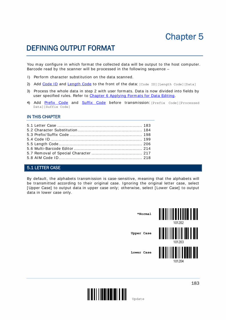
183
Update
You may configure in which format the collected data will be output to the host computer. Barcode read by the scanner will be processed in the following sequence –
1) Perform character substitution on the data scanned.
2) Add Code ID and Length Code to the front of the data:[Code ID][Length Code][Data]
3) Process the whole data in step 2 with user formats. Data is now divided into fields by user specified rules. Refer to Chapter 6 Applying Formats for Data Editing.
4) Add Prefix Code and Suffix Code before transmission:[Prefix Code][Processed Data][Suffix Code]
IN THIS CHAPTER
5.1 Letter Case .............................................................. 183 5.2 Character Substitution ............................................... 184 5.3 Prefix/Suffix Code ..................................................... 198 5.4 Code ID ................................................................... 199 5.5 Length Code ............................................................. 206 5.6 Multi-Barcode Editor .................................................. 214 5.7 Removal of Special Character ..................................... 217 5.8 AIM Code ID ............................................................. 218
5.1 LETTER CASE
By default, the alphabets transmission is case-sensitive, meaning that the alphabets will be transmitted according to their original case. Ignoring the original letter case, select [Upper Case] to output data in upper case only; otherwise, select [Lower Case] to output data in lower case only.
*Normal
Upper Case
Lower Case
Chapter 5 DEFINING OUTPUT FORMAT
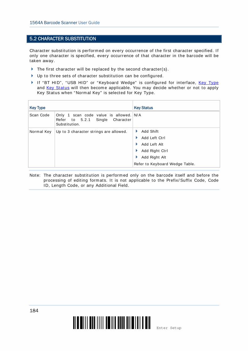
184
Enter Setup
1564A Barcode Scanner User Guide
5.2 CHARACTER SUBSTITUTION
Character substitution is performed on every occurrence of the first character specified. If only one character is specified, every occurrence of that character in the barcode will be taken away.
The first character will be replaced by the second character(s). Up to three sets of character substitution can be configured. If “BT HID”, “USB HID” or “Keyboard Wedge” is configured for interface, Key Type
and Key Status will then become applicable. You may decide whether or not to apply Key Status when “Normal Key” is selected for Key Type.
Key Type Key Status
Scan Code Only 1 scan code value is allowed. Refer to 5.2.1 Single Character Substitution.
N/A
Normal Key Up to 3 character strings are allowed. Add Shift
Add Left Ctrl
Add Left Alt
Add Right Ctrl
Add Right Alt
Refer to Keyboard Wedge Table.
Note: The character substitution is performed only on the barcode itself and before the processing of editing formats. It is not applicable to the Prefix/Suffix Code, Code ID, Length Code, or any Additional Field.
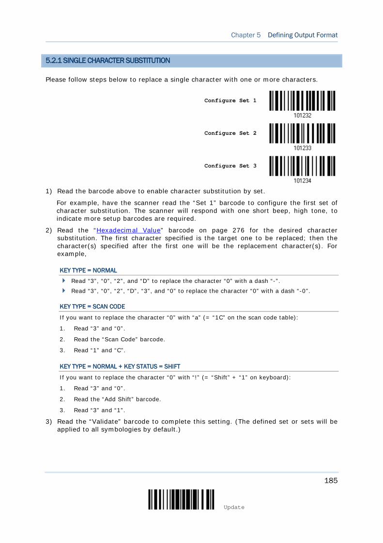
185
Update
Chapter 5 Defining Output Format
5.2.1 SINGLE CHARACTER SUBSTITUTION
Please follow steps below to replace a single character with one or more characters.
Configure Set 1
Configure Set 2
Configure Set 3
1) Read the barcode above to enable character substitution by set.
For example, have the scanner read the “Set 1” barcode to configure the first set of character substitution. The scanner will respond with one short beep, high tone, to indicate more setup barcodes are required.
2) Read the “Hexadecimal Value” barcode on page 276 for the desired character substitution. The first character specified is the target one to be replaced; then the character(s) specified after the first one will be the replacement character(s). For example,
KEY TYPE = NORMAL
Read “3”, “0”, “2”, and “D” to replace the character “0” with a dash “-”.
Read “3”, “0”, “2”, “D”, “3”, and “0” to replace the character “0” with a dash “-0”.
KEY TYPE = SCAN CODE
If you want to replace the character “0” with “a” (= “1C” on the scan code table):
1. Read “3” and “0”.
2. Read the “Scan Code” barcode.
3. Read “1” and “C”.
KEY TYPE = NORMAL + KEY STATUS = SHIFT
If you want to replace the character “0” with “!” (= “Shift” + “1” on keyboard):
1. Read “3” and “0”.
2. Read the “Add Shift” barcode.
3. Read “3” and “1”.
3) Read the “Validate” barcode to complete this setting. (The defined set or sets will be applied to all symbologies by default.)
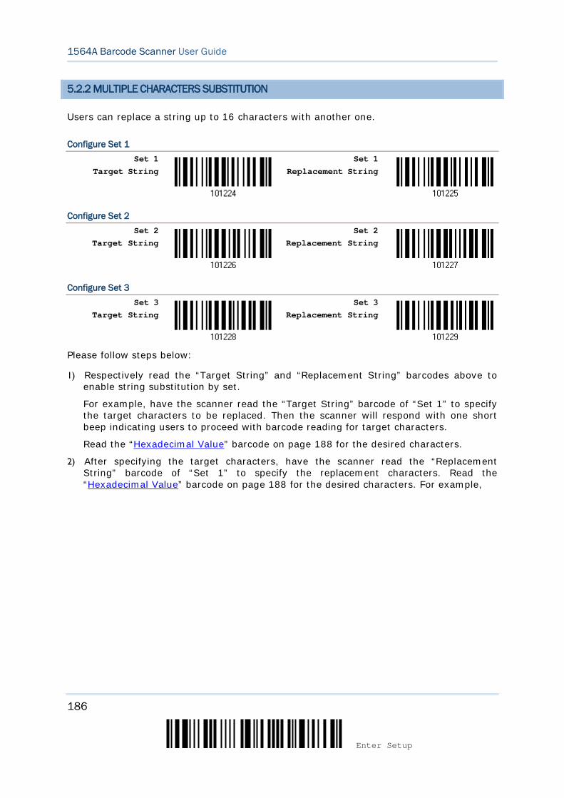
186
Enter Setup
1564A Barcode Scanner User Guide
5.2.2 MULTIPLE CHARACTERS SUBSTITUTION
Users can replace a string up to 16 characters with another one.
Configure Set 1 Set 1
Target String
Set 1 Replacement String
Configure Set 2 Set 2
Target String
Set 2 Replacement String
Configure Set 3 Set 3
Target String
Set 3 Replacement String
Please follow steps below:
1) Respectively read the “Target String” and “Replacement String” barcodes above to enable string substitution by set.
For example, have the scanner read the “Target String” barcode of “Set 1” to specify the target characters to be replaced. Then the scanner will respond with one short beep indicating users to proceed with barcode reading for target characters.
Read the “Hexadecimal Value” barcode on page 188 for the desired characters.
2) After specifying the target characters, have the scanner read the “Replacement String” barcode of “Set 1” to specify the replacement characters. Read the “Hexadecimal Value” barcode on page 188 for the desired characters. For example,
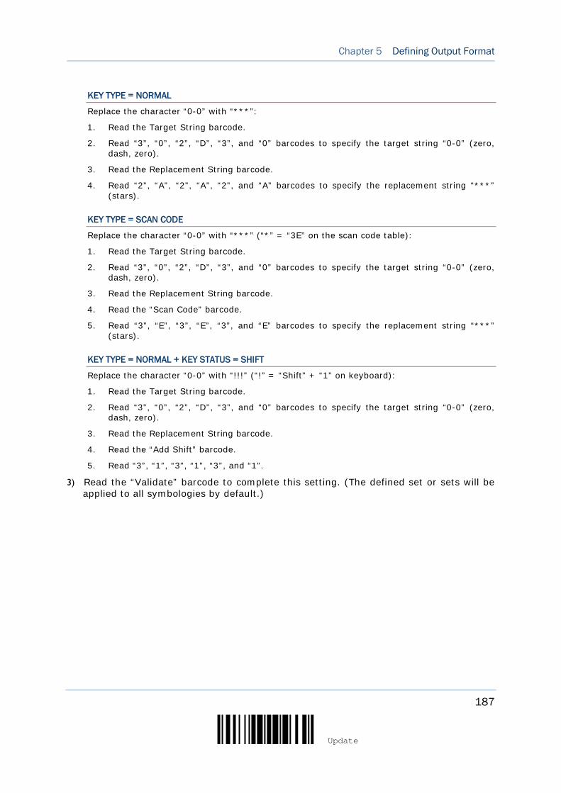
187
Update
Chapter 5 Defining Output Format
KEY TYPE = NORMAL
Replace the character “0-0” with “***”:
1. Read the Target String barcode.
2. Read “3”, “0”, “2”, “D”, “3”, and “0” barcodes to specify the target string “0-0” (zero, dash, zero).
3. Read the Replacement String barcode.
4. Read “2”, “A”, “2”, “A”, “2”, and “A” barcodes to specify the replacement string “***” (stars).
KEY TYPE = SCAN CODE
Replace the character “0-0” with “***” (“*” = “3E” on the scan code table):
1. Read the Target String barcode.
2. Read “3”, “0”, “2”, “D”, “3”, and “0” barcodes to specify the target string “0-0” (zero, dash, zero).
3. Read the Replacement String barcode.
4. Read the “Scan Code” barcode.
5. Read “3”, “E”, “3”, “E”, “3”, and “E” barcodes to specify the replacement string “***” (stars).
KEY TYPE = NORMAL + KEY STATUS = SHIFT
Replace the character “0-0” with “!!!” (“!” = “Shift” + “1” on keyboard):
1. Read the Target String barcode.
2. Read “3”, “0”, “2”, “D”, “3”, and “0” barcodes to specify the target string “0-0” (zero, dash, zero).
3. Read the Replacement String barcode.
4. Read the “Add Shift” barcode.
5. Read “3”, “1”, “3”, “1”, “3”, and “1”.
3) Read the “Validate” barcode to complete this setting. (The defined set or sets will be applied to all symbologies by default.)
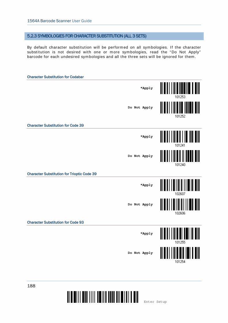
188
Enter Setup
1564A Barcode Scanner User Guide
5.2.3 SYMBOLOGIES FOR CHARACTER SUBSTITUTION (ALL 3 SETS)
By default character substitution will be performed on all symbologies. If the character substitution is not desired with one or more symbologies, read the “Do Not Apply” barcode for each undesired symbologies and all the three sets will be ignored for them.
Character Substitution for Codabar
*Apply
Do Not Apply
Character Substitution for Code 39
*Apply
Do Not Apply
Character Substitution for Trioptic Code 39
*Apply
Do Not Apply
Character Substitution for Code 93
*Apply
Do Not Apply
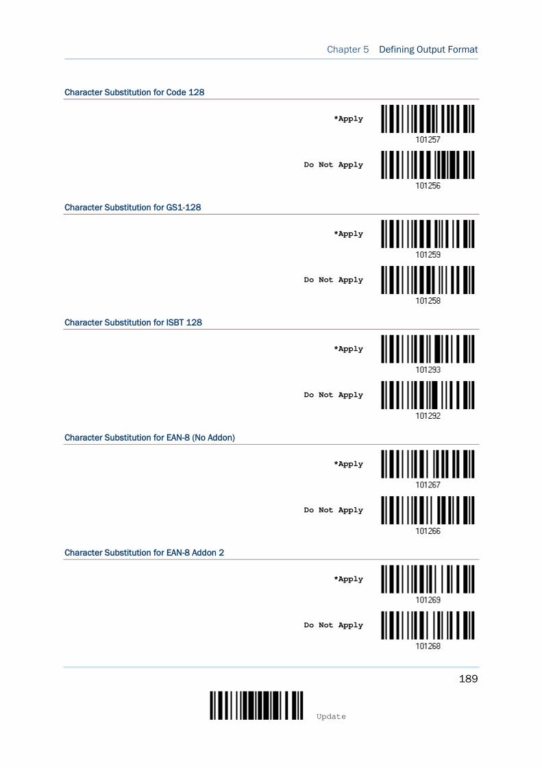
189
Update
Chapter 5 Defining Output Format
Character Substitution for Code 128
*Apply
Do Not Apply
Character Substitution for GS1-128
*Apply
Do Not Apply
Character Substitution for ISBT 128
*Apply
Do Not Apply
Character Substitution for EAN-8 (No Addon)
*Apply
Do Not Apply
Character Substitution for EAN-8 Addon 2
*Apply
Do Not Apply
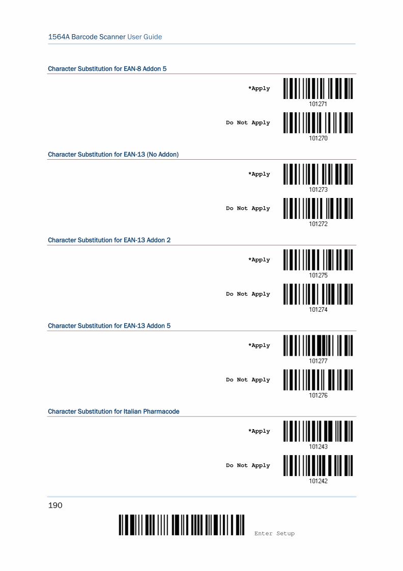
190
Enter Setup
1564A Barcode Scanner User Guide
Character Substitution for EAN-8 Addon 5
*Apply
Do Not Apply
Character Substitution for EAN-13 (No Addon)
*Apply
Do Not Apply
Character Substitution for EAN-13 Addon 2
*Apply
Do Not Apply
Character Substitution for EAN-13 Addon 5
*Apply
Do Not Apply
Character Substitution for Italian Pharmacode
*Apply
Do Not Apply
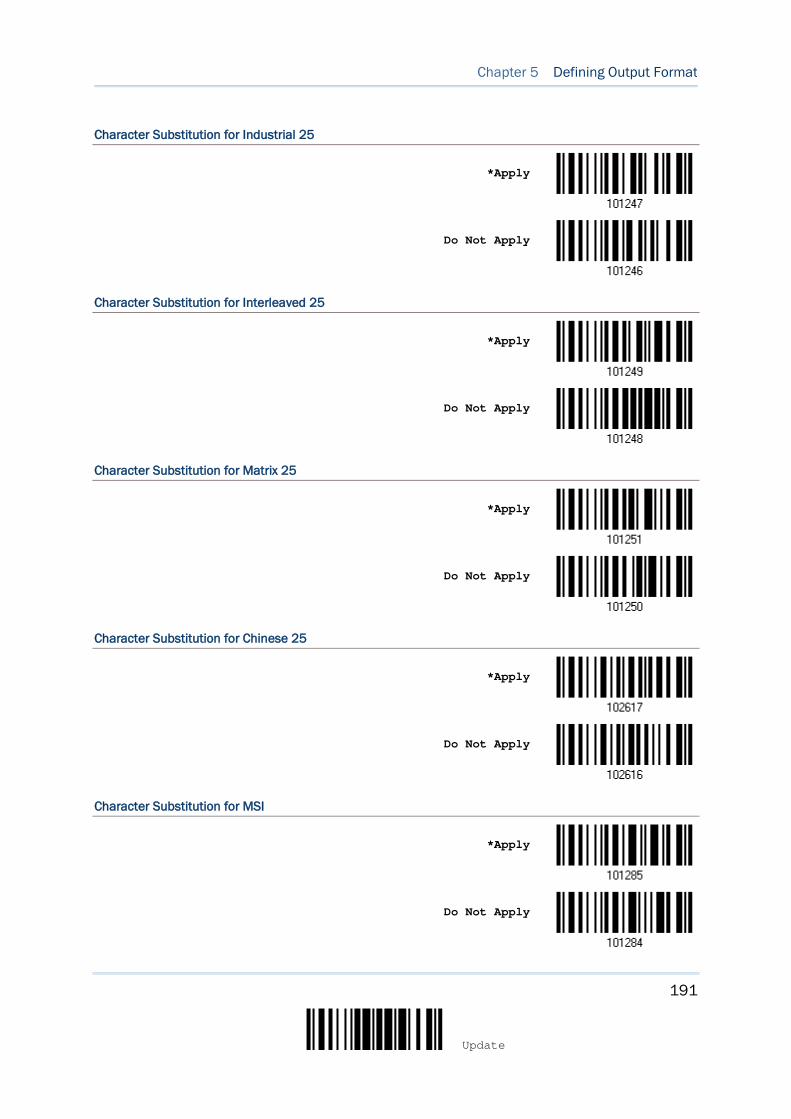
191
Update
Chapter 5 Defining Output Format
Character Substitution for Industrial 25
*Apply
Do Not Apply
Character Substitution for Interleaved 25
*Apply
Do Not Apply
Character Substitution for Matrix 25
*Apply
Do Not Apply
Character Substitution for Chinese 25
*Apply
Do Not Apply
Character Substitution for MSI
*Apply
Do Not Apply
192
Enter Setup
1564A Barcode Scanner User Guide
Character Substitution for GS1 DataBar
*Apply
Do Not Apply
Character Substitution for UPC-A (No Addon)
*Apply
Do Not Apply
Character Substitution for UPC-A Addon 2
*Apply
Do Not Apply
Character Substitution for UPC-A Addon 5
*Apply
Do Not Apply
Character Substitution for UPC-E (No Addon)
*Apply
Do Not Apply
193
Update
Chapter 5 Defining Output Format
Character Substitution for UPC-E Addon 2
*Apply
Do Not Apply
Character Substitution for UPC-E Addon 5
*Apply
Do Not Apply
Character Substitution for UCC Coupon Extended Code
*Apply
Do Not Apply
Character Substitution for Code 11
*Apply
Do Not Apply
Character Substitution for Composite CC-A/B
*Apply
Do Not Apply
194
Enter Setup
1564A Barcode Scanner User Guide
Character Substitution for Composite CC-C
*Apply
Do Not Apply
Character Substitution for Composite TLC-39
*Apply
Do Not Apply
Character Substitution for US Postnet
*Apply
Do Not Apply
Character Substitution for US Planet
*Apply
Do Not Apply
Character Substitution for UK Postal
*Apply
Do Not Apply
195
Update
Chapter 5 Defining Output Format
Character Substitution for Japan Postal
*Apply
Do Not Apply
Character Substitution for Australian Postal
*Apply
Do Not Apply
Character Substitution for Dutch Postal
*Apply
Do Not Apply
Character Substitution for USPS 4CB/One Code/Intelligent Mail
*Apply
Do Not Apply
Character Substitution for UPU FICS Postal
*Apply
Do Not Apply
196
Enter Setup
1564A Barcode Scanner User Guide
Character Substitution for PDF417
*Apply
Do Not Apply
Character Substitution for MicroPDF417
*Apply
Do Not Apply
Character Substitution for Data Matrix
*Apply
Do Not Apply
Character Substitution for Maxicode
*Apply
Do Not Apply
Character Substitution for QR Code
*Apply
Do Not Apply
197
Update
Chapter 5 Defining Output Format
Character Substitution for MicroQR
*Apply
Do Not Apply
Character Substitution for Aztec
*Apply
Do Not Apply
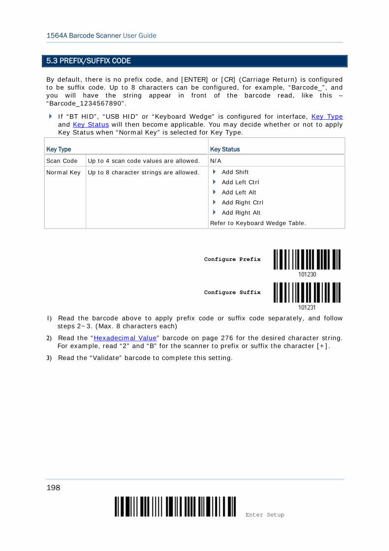
198
Enter Setup
1564A Barcode Scanner User Guide
5.3 PREFIX/SUFFIX CODE
By default, there is no prefix code, and [ENTER] or [CR] (Carriage Return) is configured to be suffix code. Up to 8 characters can be configured, for example, “Barcode_”, and you will have the string appear in front of the barcode read, like this – “Barcode_1234567890”.
If “BT HID”, “USB HID” or “Keyboard Wedge” is configured for interface, Key Type and Key Status will then become applicable. You may decide whether or not to apply Key Status when “Normal Key” is selected for Key Type.
Key Type Key Status
Scan Code Up to 4 scan code values are allowed. N/A
Normal Key Up to 8 character strings are allowed. Add Shift
Add Left Ctrl
Add Left Alt
Add Right Ctrl
Add Right Alt
Refer to Keyboard Wedge Table.
Configure Prefix
Configure Suffix
1) Read the barcode above to apply prefix code or suffix code separately, and follow
steps 2~3. (Max. 8 characters each)
2) Read the “Hexadecimal Value” barcode on page 276 for the desired character string. For example, read “2” and “B” for the scanner to prefix or suffix the character [+].
3) Read the “Validate” barcode to complete this setting.
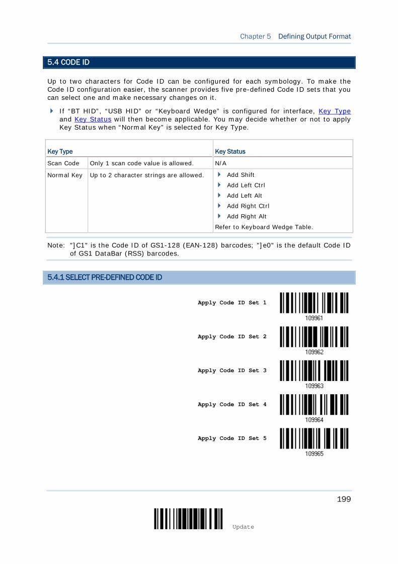
199
Update
Chapter 5 Defining Output Format
5.4 CODE ID
Up to two characters for Code ID can be configured for each symbology. To make the Code ID configuration easier, the scanner provides five pre-defined Code ID sets that you can select one and make necessary changes on it.
If “BT HID”, “USB HID” or “Keyboard Wedge” is configured for interface, Key Type and Key Status will then become applicable. You may decide whether or not to apply Key Status when “Normal Key” is selected for Key Type.
Key Type Key Status
Scan Code Only 1 scan code value is allowed. N/A
Normal Key Up to 2 character strings are allowed. Add Shift
Add Left Ctrl
Add Left Alt
Add Right Ctrl
Add Right Alt
Refer to Keyboard Wedge Table.
Note: "]C1" is the Code ID of GS1-128 (EAN-128) barcodes; "]e0" is the default Code ID of GS1 DataBar (RSS) barcodes.
5.4.1 SELECT PRE-DEFINED CODE ID
Apply Code ID Set 1
Apply Code ID Set 2
Apply Code ID Set 3
Apply Code ID Set 4
Apply Code ID Set 5
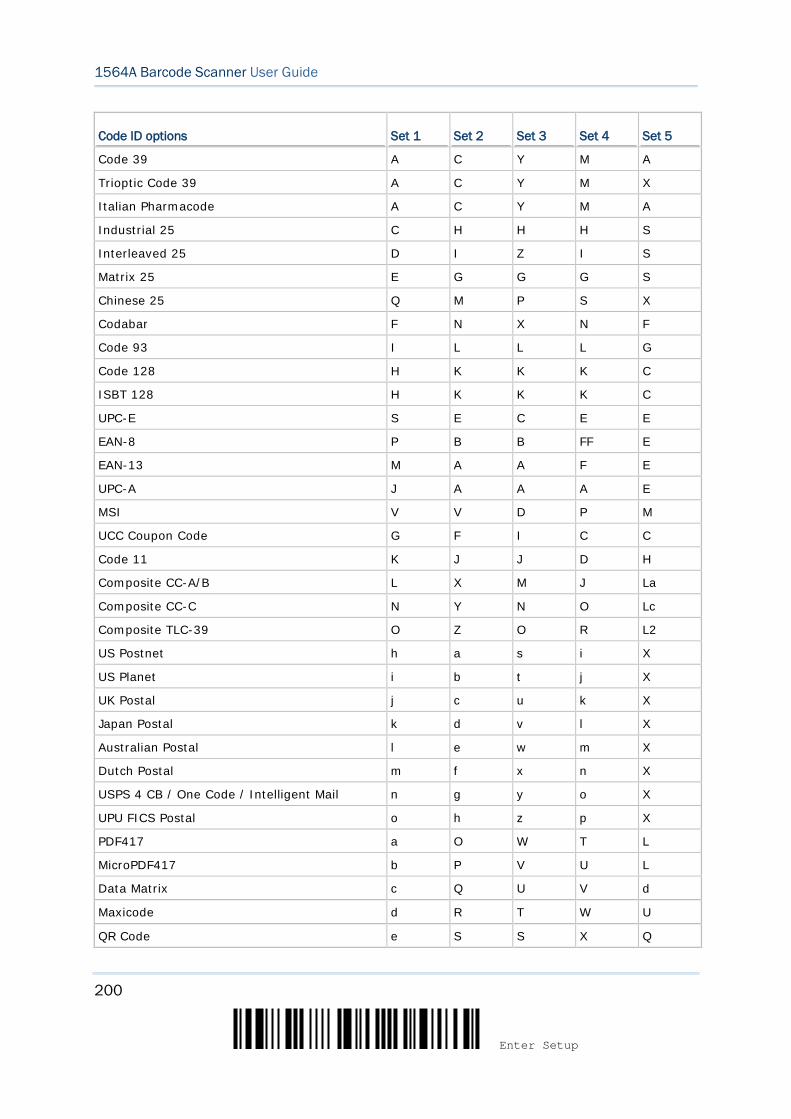
200
Enter Setup
1564A Barcode Scanner User Guide
Code ID options Set 1 Set 2 Set 3 Set 4 Set 5
Code 39 A C Y M A
Trioptic Code 39 A C Y M X
Italian Pharmacode A C Y M A
Industrial 25 C H H H S
Interleaved 25 D I Z I S
Matrix 25 E G G G S
Chinese 25 Q M P S X
Codabar F N X N F
Code 93 I L L L G
Code 128 H K K K C
ISBT 128 H K K K C
UPC-E S E C E E
EAN-8 P B B FF E
EAN-13 M A A F E
UPC-A J A A A E
MSI V V D P M
UCC Coupon Code G F I C C
Code 11 K J J D H
Composite CC-A/B L X M J La
Composite CC-C N Y N O Lc
Composite TLC-39 O Z O R L2
US Postnet h a s i X
US Planet i b t j X
UK Postal j c u k X
Japan Postal k d v l X
Australian Postal l e w m X
Dutch Postal m f x n X
USPS 4 CB / One Code / Intelligent Mail n g y o X
UPU FICS Postal o h z p X
PDF417 a O W T L
MicroPDF417 b P V U L
Data Matrix c Q U V d
Maxicode d R T W U
QR Code e S S X Q

201
Update
Chapter 5 Defining Output Format
MicroQR f T R Y Q
Aztec g U Q Z z
IATA z z r h S
Macro PDF417 p i a q L
Macro MicroPDF417 q j b r L
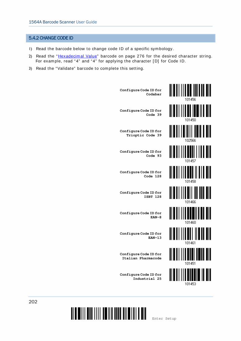
202
Enter Setup
1564A Barcode Scanner User Guide
5.4.2 CHANGE CODE ID
1) Read the barcode below to change code ID of a specific symbology.
2) Read the “Hexadecimal Value” barcode on page 276 for the desired character string. For example, read “4” and “4” for applying the character [D] for Code ID.
3) Read the “Validate” barcode to complete this setting.
Configure Code ID for
Codabar
Configure Code ID for Code 39
Configure Code ID for Trioptic Code 39
Configure Code ID for Code 93
Configure Code ID for Code 128
Configure Code ID for ISBT 128
Configure Code ID for EAN-8
Configure Code ID for EAN-13
Configure Code ID for Italian Pharmacode
Configure Code ID for Industrial 25
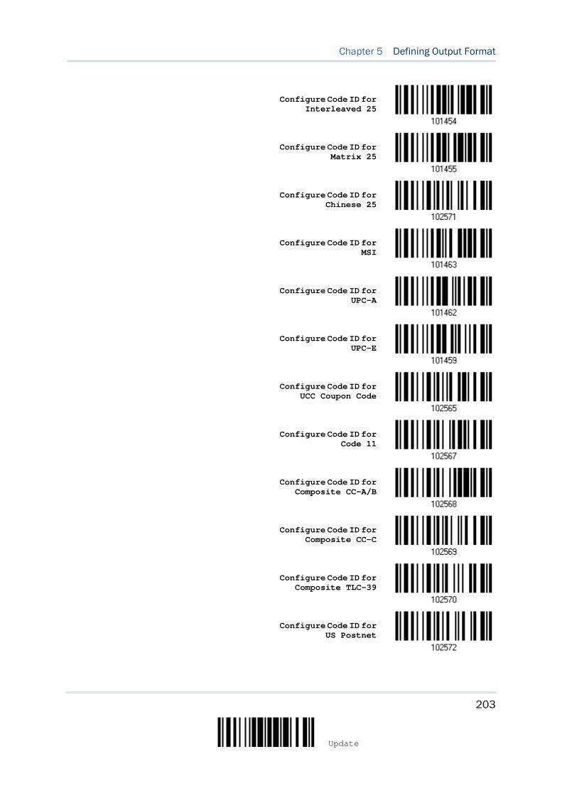
203
Update
Chapter 5 Defining Output Format
Configure Code ID for
Interleaved 25
Configure Code ID for Matrix 25
Configure Code ID for Chinese 25
Configure Code ID for MSI
Configure Code ID for UPC-A
Configure Code ID for UPC-E
Configure Code ID for UCC Coupon Code
Configure Code ID for Code 11
Configure Code ID for Composite CC-A/B
Configure Code ID for Composite CC-C
Configure Code ID for Composite TLC-39
Configure Code ID for US Postnet
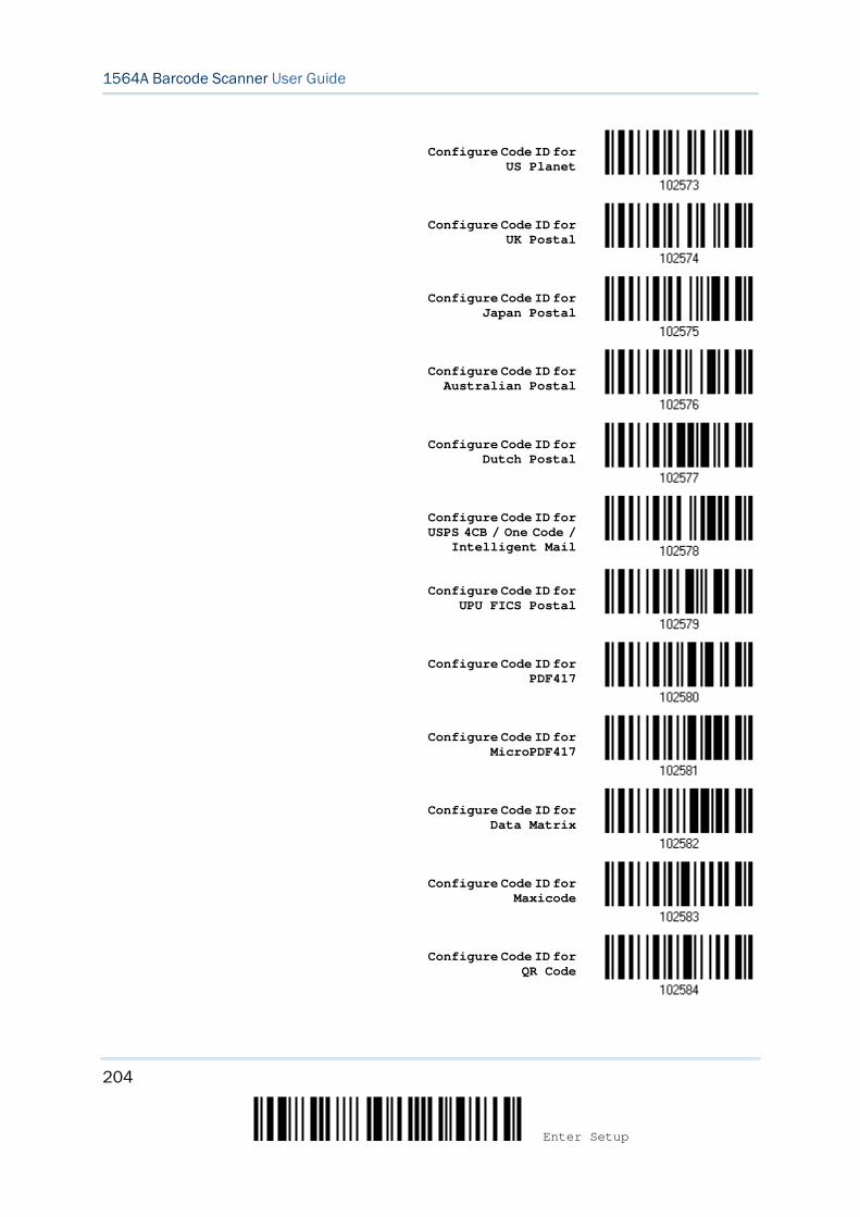
204
Enter Setup
1564A Barcode Scanner User Guide
Configure Code ID for
US Planet
Configure Code ID for UK Postal
Configure Code ID for Japan Postal
Configure Code ID for Australian Postal
Configure Code ID for Dutch Postal
Configure Code ID for USPS 4CB / One Code /
Intelligent Mail
Configure Code ID for
UPU FICS Postal
Configure Code ID for PDF417
Configure Code ID for MicroPDF417
Configure Code ID for Data Matrix
Configure Code ID for Maxicode
Configure Code ID for QR Code
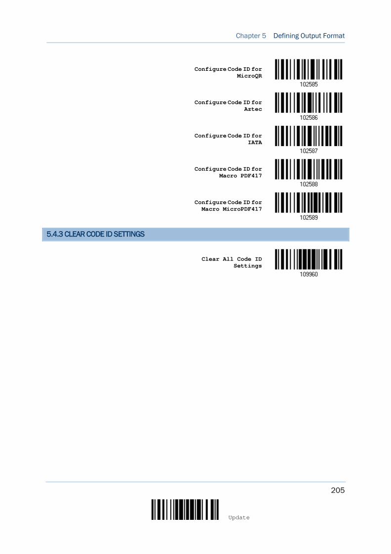
205
Update
Chapter 5 Defining Output Format
Configure Code ID for
MicroQR
Configure Code ID for Aztec
Configure Code ID for IATA
Configure Code ID for Macro PDF417
Configure Code ID for Macro MicroPDF417
5.4.3 CLEAR CODE ID SETTINGS
Clear All Code ID
Settings
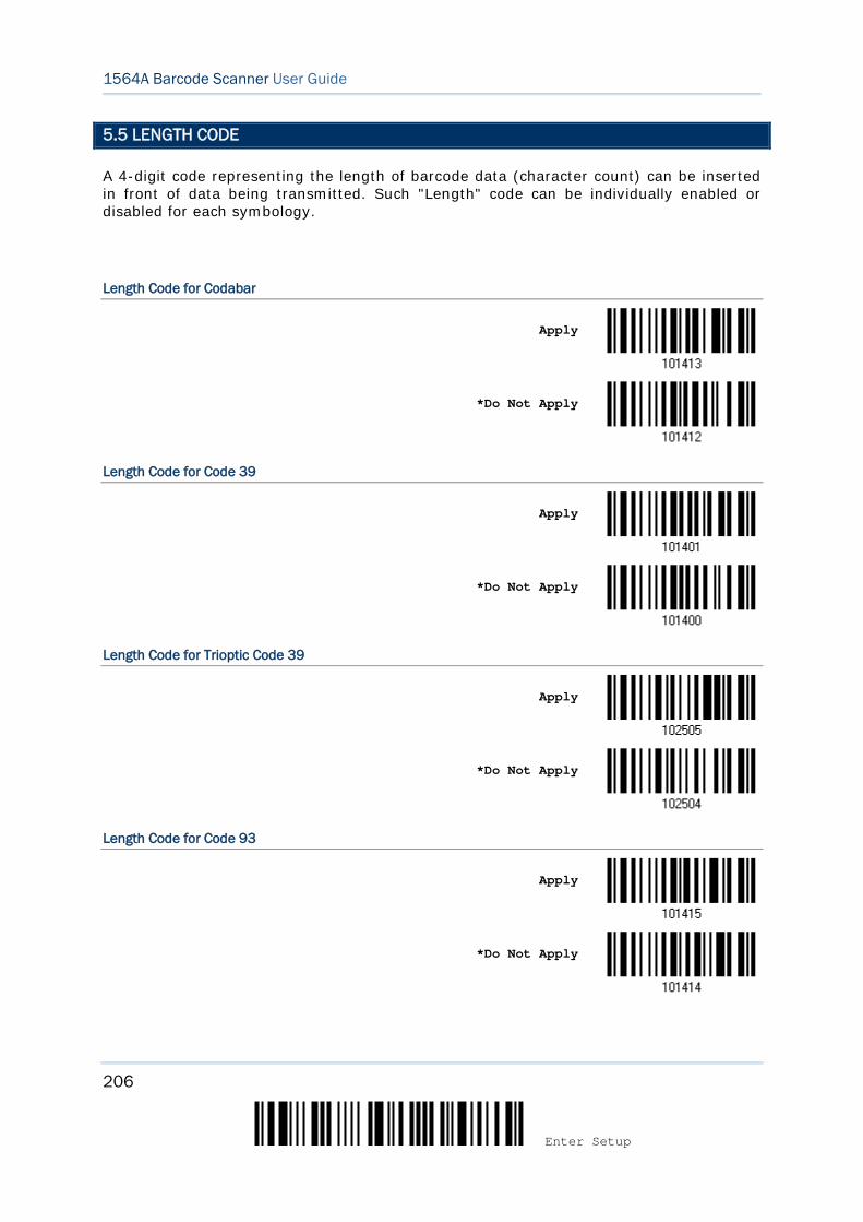
206
Enter Setup
1564A Barcode Scanner User Guide
5.5 LENGTH CODE
A 4-digit code representing the length of barcode data (character count) can be inserted in front of data being transmitted. Such "Length" code can be individually enabled or disabled for each symbology.
Length Code for Codabar
Apply
*Do Not Apply
Length Code for Code 39
Apply
*Do Not Apply
Length Code for Trioptic Code 39
Apply
*Do Not Apply
Length Code for Code 93
Apply
*Do Not Apply
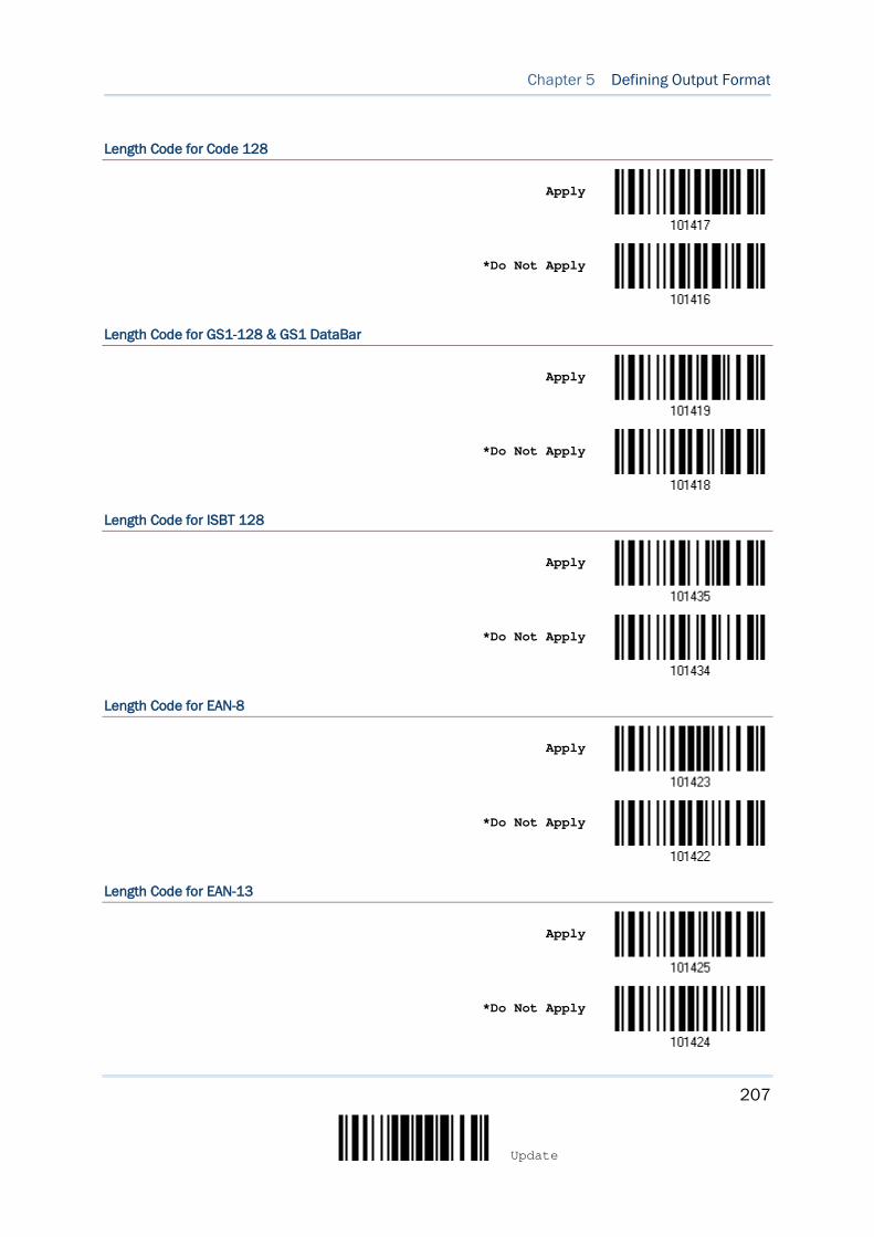
207
Update
Chapter 5 Defining Output Format
Length Code for Code 128
Apply
*Do Not Apply
Length Code for GS1-128 & GS1 DataBar
Apply
*Do Not Apply
Length Code for ISBT 128
Apply
*Do Not Apply
Length Code for EAN-8
Apply
*Do Not Apply
Length Code for EAN-13
Apply
*Do Not Apply
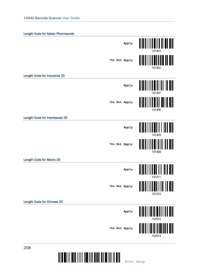
208
Enter Setup
1564A Barcode Scanner User Guide
Length Code for Italian Pharmacode
Apply
*Do Not Apply
Length Code for Industrial 25
Apply
*Do Not Apply
Length Code for Interleaved 25
Apply
*Do Not Apply
Length Code for Matrix 25
Apply
*Do Not Apply
Length Code for Chinese 25
Apply
*Do Not Apply

209
Update
Chapter 5 Defining Output Format
Length Code for MSI
Apply
*Do Not Apply
Length Code for UPC-A
Apply
*Do Not Apply
Length Code for UPC-E
Apply
*Do Not Apply
Length Code for UCC Coupon Extended Code
Apply
*Do Not Apply
Length Code for Code 11
Apply
*Do Not Apply
210
Enter Setup
1564A Barcode Scanner User Guide
Length Code for Composite CC-A/B
Apply
*Do Not Apply
Length Code for Composite CC-C
Apply
*Do Not Apply
Length Code for Composite TLC-39
Apply
*Do Not Apply
Length Code for US Postnet
Apply
*Do Not Apply
Length Code for US Planet
Apply
*Do Not Apply
211
Update
Chapter 5 Defining Output Format
Length Code for UK Postal
Apply
*Do Not Apply
Length Code for Japan Postal
Apply
*Do Not Apply
Length Code for Australian Postal
Apply
*Do Not Apply
Length Code for Dutch Postal
Apply
*Do Not Apply
Length Code for USPS 4CB/One Code/Intelligent Mail
Apply
*Do Not Apply
212
Enter Setup
1564A Barcode Scanner User Guide
Length Code for UPU FICS Postal
Apply
*Do Not Apply
Length Code for PDF417
Apply
*Do Not Apply
Length Code for MicroPDF417
Apply
*Do Not Apply
Length Code for Data Matrix
Apply
*Do Not Apply
Length Code for Maxicode
Apply
*Do Not Apply
213
Update
Chapter 5 Defining Output Format
Length Code for QR Code
Apply
*Do Not Apply
Length Code for MicroQR
Apply
*Do Not Apply
Length Code for Aztec
Apply
*Do Not Apply
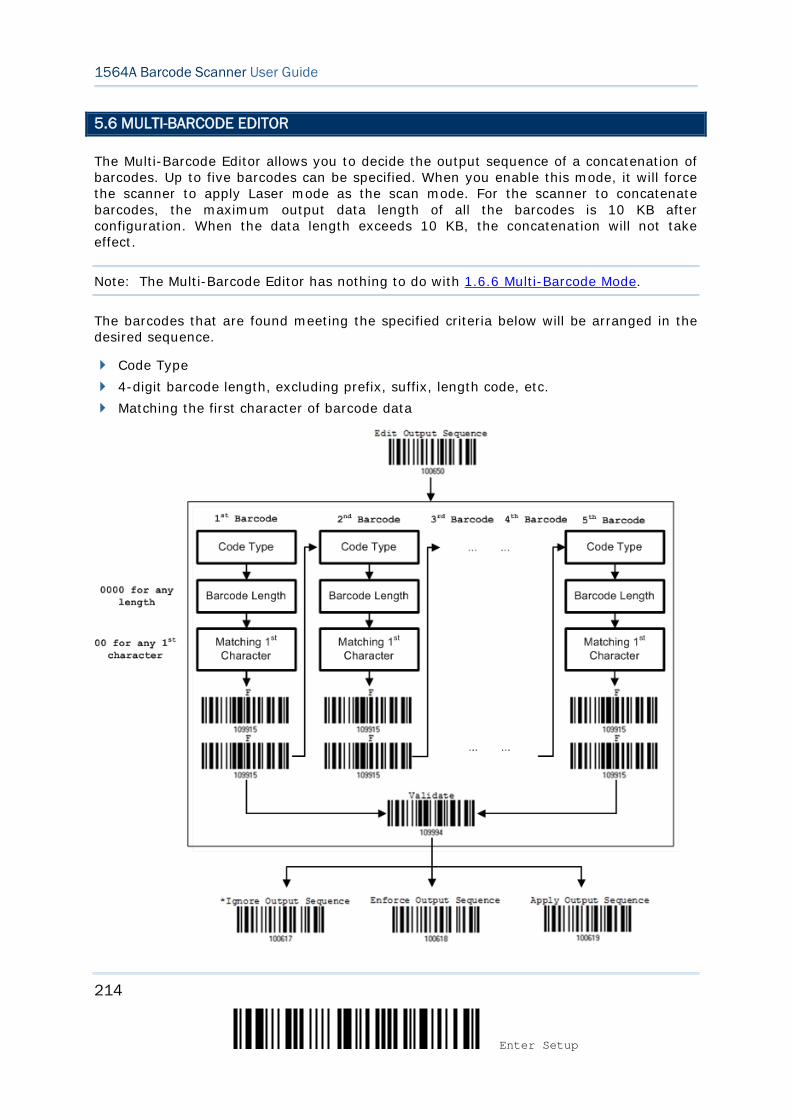
214
Enter Setup
1564A Barcode Scanner User Guide
5.6 MULTI-BARCODE EDITOR
The Multi-Barcode Editor allows you to decide the output sequence of a concatenation of barcodes. Up to five barcodes can be specified. When you enable this mode, it will force the scanner to apply Laser mode as the scan mode. For the scanner to concatenate barcodes, the maximum output data length of all the barcodes is 10 KB after configuration. When the data length exceeds 10 KB, the concatenation will not take effect.
Note: The Multi-Barcode Editor has nothing to do with 1.6.6 Multi-Barcode Mode.
The barcodes that are found meeting the specified criteria below will be arranged in the desired sequence.
Code Type 4-digit barcode length, excluding prefix, suffix, length code, etc. Matching the first character of barcode data
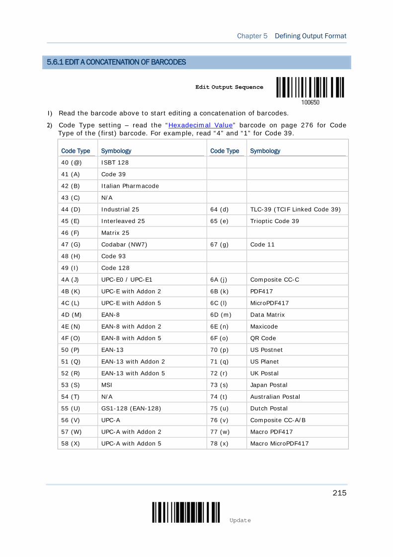
215
Update
Chapter 5 Defining Output Format
5.6.1 EDIT A CONCATENATION OF BARCODES
Edit Output Sequence
1) Read the barcode above to start editing a concatenation of barcodes.
2) Code Type setting – read the “Hexadecimal Value” barcode on page 276 for Code Type of the (first) barcode. For example, read “4” and “1” for Code 39.
Code Type Symbology Code Type Symbology
40 (@) ISBT 128
41 (A) Code 39
42 (B) Italian Pharmacode
43 (C) N/A
44 (D) Industrial 25 64 (d) TLC-39 (TCIF Linked Code 39)
45 (E) Interleaved 25 65 (e) Trioptic Code 39
46 (F) Matrix 25
47 (G) Codabar (NW7) 67 (g) Code 11
48 (H) Code 93
49 (I) Code 128
4A (J) UPC-E0 / UPC-E1 6A (j) Composite CC-C
4B (K) UPC-E with Addon 2 6B (k) PDF417
4C (L) UPC-E with Addon 5 6C (l) MicroPDF417
4D (M) EAN-8 6D (m) Data Matrix
4E (N) EAN-8 with Addon 2 6E (n) Maxicode
4F (O) EAN-8 with Addon 5 6F (o) QR Code
50 (P) EAN-13 70 (p) US Postnet
51 (Q) EAN-13 with Addon 2 71 (q) US Planet
52 (R) EAN-13 with Addon 5 72 (r) UK Postal
53 (S) MSI 73 (s) Japan Postal
54 (T) N/A 74 (t) Australian Postal
55 (U) GS1-128 (EAN-128) 75 (u) Dutch Postal
56 (V) UPC-A 76 (v) Composite CC-A/B
57 (W) UPC-A with Addon 2 77 (w) Macro PDF417
58 (X) UPC-A with Addon 5 78 (x) Macro MicroPDF417
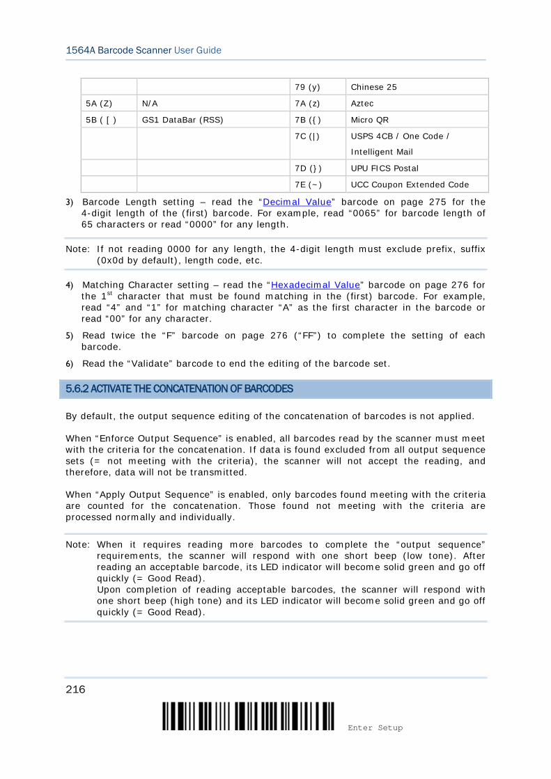
216
Enter Setup
1564A Barcode Scanner User Guide
79 (y) Chinese 25
5A (Z) N/A 7A (z) Aztec
5B ( [ ) GS1 DataBar (RSS) 7B ({) Micro QR
7C (|) USPS 4CB / One Code /
Intelligent Mail
7D (}) UPU FICS Postal
7E (~) UCC Coupon Extended Code
3) Barcode Length setting – read the “Decimal Value” barcode on page 275 for the 4-digit length of the (first) barcode. For example, read “0065” for barcode length of 65 characters or read “0000” for any length.
Note: If not reading 0000 for any length, the 4-digit length must exclude prefix, suffix (0x0d by default), length code, etc.
4) Matching Character setting – read the “Hexadecimal Value” barcode on page 276 for the 1st character that must be found matching in the (first) barcode. For example, read “4” and “1” for matching character “A” as the first character in the barcode or read “00” for any character.
5) Read twice the “F” barcode on page 276 (“FF”) to complete the setting of each barcode.
6) Read the “Validate” barcode to end the editing of the barcode set.
5.6.2 ACTIVATE THE CONCATENATION OF BARCODES
By default, the output sequence editing of the concatenation of barcodes is not applied.
When “Enforce Output Sequence” is enabled, all barcodes read by the scanner must meet with the criteria for the concatenation. If data is found excluded from all output sequence sets (= not meeting with the criteria), the scanner will not accept the reading, and therefore, data will not be transmitted.
When “Apply Output Sequence” is enabled, only barcodes found meeting with the criteria are counted for the concatenation. Those found not meeting with the criteria are processed normally and individually.
Note: When it requires reading more barcodes to complete the “output sequence” requirements, the scanner will respond with one short beep (low tone). After reading an acceptable barcode, its LED indicator will become solid green and go off quickly (= Good Read). Upon completion of reading acceptable barcodes, the scanner will respond with one short beep (high tone) and its LED indicator will become solid green and go off quickly (= Good Read).
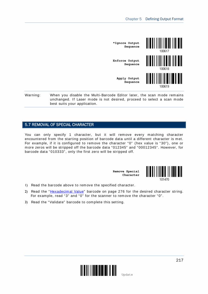
217
Update
Chapter 5 Defining Output Format
*Ignore Output
Sequence
Enforce Output Sequence
Apply Output Sequence
Warning: When you disable the Multi-Barcode Editor later, the scan mode remains unchanged. If Laser mode is not desired, proceed to select a scan mode best suits your application.
5.7 REMOVAL OF SPECIAL CHARACTER
You can only specify 1 character, but it will remove every matching character encountered from the starting position of barcode data until a different character is met. For example, if it is configured to remove the character “0” (hex value is “30”), one or more zeros will be stripped off the barcode data “012345” and “00012345”. However, for barcode data “010333”, only the first zero will be stripped off.
Remove Special
Character
1) Read the barcode above to remove the specified character.
2) Read the “Hexadecimal Value” barcode on page 276 for the desired character string. For example, read “3” and “0” for the scanner to remove the character “0”.
3) Read the “Validate” barcode to complete this setting.

218
Enter Setup
1564A Barcode Scanner User Guide
5.8 AIM CODE ID
You can add an AIM (Automatic Identification and Mobility) code ID in front of the barcode that shares the common purpose of identifying, tracking, recording, storing, and communicating essential business, personal, or product data. Enabling this function can have the scanner be capable of fast and accurate data collection and search.
*Disable
Enable
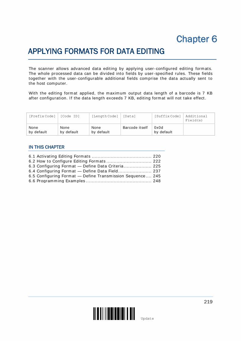
219
Update
The scanner allows advanced data editing by applying user-configured editing formats. The whole processed data can be divided into fields by user-specified rules. These fields together with the user-configurable additional fields comprise the data actually sent to the host computer.
With the editing format applied, the maximum output data length of a barcode is 7 KB after configuration. If the data length exceeds 7 KB, editing format will not take effect.
[Prefix Code] [Code ID] [Length Code] [Data] [Suffix Code] Additional Field(s)
None by default
None by default
None by default
Barcode itself 0x0d by default
IN THIS CHAPTER
6.1 Activating Editing Formats ......................................... 220 6.2 How to Configure Editing Formats ............................... 222 6.3 Configuring Format — Define Data Criteria ................... 225 6.4 Configuring Format — Define Data Field ....................... 237 6.5 Configuring Format — Define Transmission Sequence .... 245 6.6 Programming Examples ............................................. 248
Chapter 6 APPLYING FORMATS FOR DATA EDITING
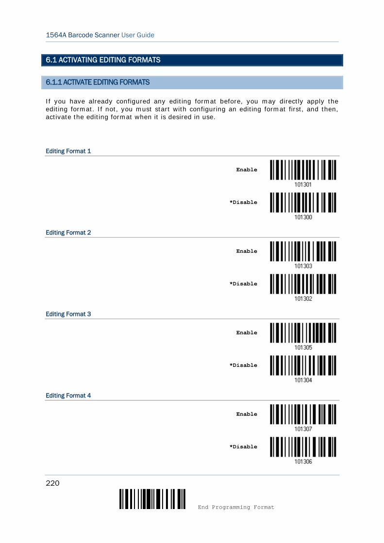
220
End Programming Format
1564A Barcode Scanner User Guide
6.1 ACTIVATING EDITING FORMATS
6.1.1 ACTIVATE EDITING FORMATS
If you have already configured any editing format before, you may directly apply the editing format. If not, you must start with configuring an editing format first, and then, activate the editing format when it is desired in use.
Editing Format 1
Enable
*Disable
Editing Format 2
Enable
*Disable
Editing Format 3
Enable
*Disable
Editing Format 4
Enable
*Disable
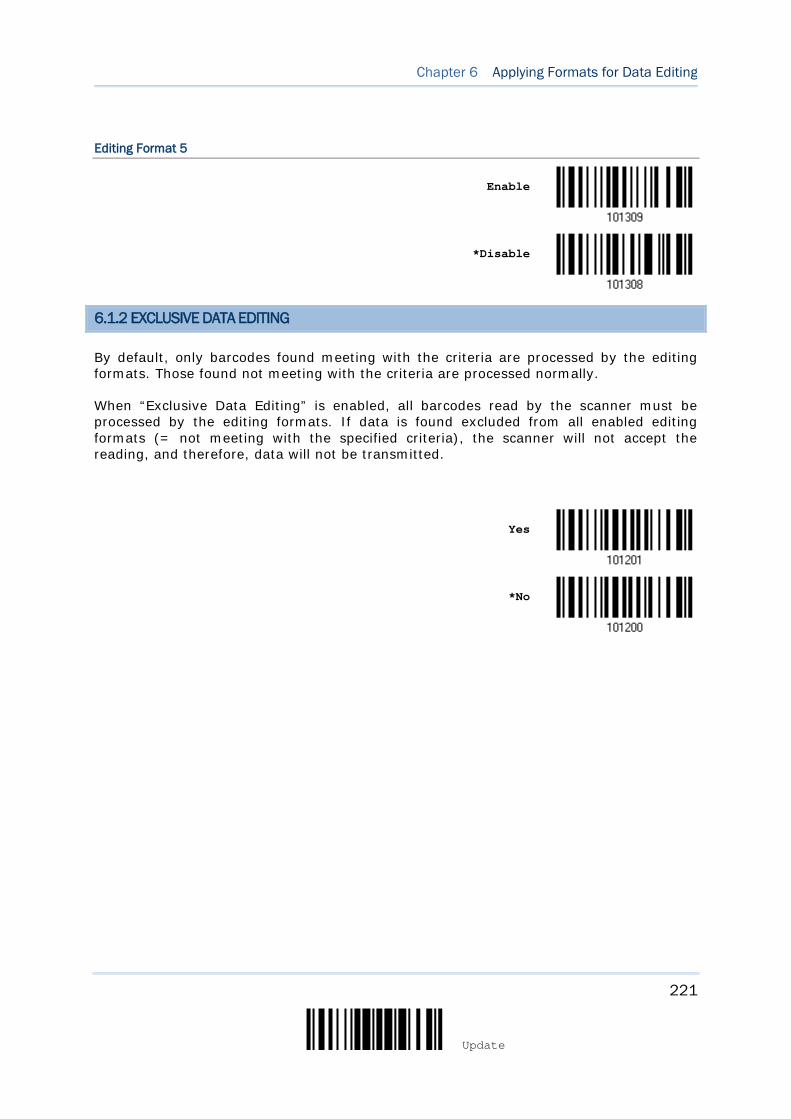
221
Update
Chapter 6 Applying Formats for Data Editing
Editing Format 5
Enable
*Disable
6.1.2 EXCLUSIVE DATA EDITING
By default, only barcodes found meeting with the criteria are processed by the editing formats. Those found not meeting with the criteria are processed normally.
When “Exclusive Data Editing” is enabled, all barcodes read by the scanner must be processed by the editing formats. If data is found excluded from all enabled editing formats (= not meeting with the specified criteria), the scanner will not accept the reading, and therefore, data will not be transmitted.
Yes
*No

222
End Programming Format
1564A Barcode Scanner User Guide
6.2 HOW TO CONFIGURE EDITING FORMATS
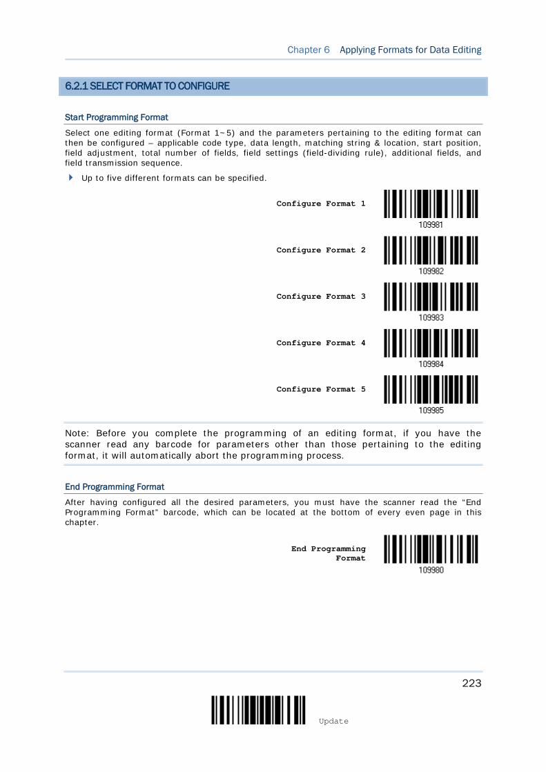
223
Update
Chapter 6 Applying Formats for Data Editing
6.2.1 SELECT FORMAT TO CONFIGURE
Start Programming Format
Select one editing format (Format 1~5) and the parameters pertaining to the editing format can then be configured – applicable code type, data length, matching string & location, start position, field adjustment, total number of fields, field settings (field-dividing rule), additional fields, and field transmission sequence.
Up to five different formats can be specified.
Configure Format 1
Configure Format 2
Configure Format 3
Configure Format 4
Configure Format 5
Note: Before you complete the programming of an editing format, if you have the scanner read any barcode for parameters other than those pertaining to the editing format, it will automatically abort the programming process.
End Programming Format
After having configured all the desired parameters, you must have the scanner read the “End Programming Format” barcode, which can be located at the bottom of every even page in this chapter.
End Programming Format
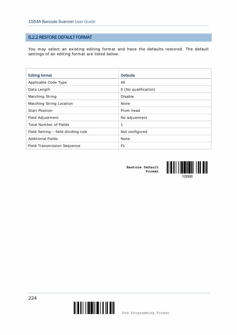
224
End Programming Format
1564A Barcode Scanner User Guide
6.2.2 RESTORE DEFAULT FORMAT
You may select an existing editing format and have the defaults restored. The default settings of an editing format are listed below.
Editing format Defaults
Applicable Code Type All
Data Length 0 (No qualification)
Matching String Disable
Matching String Location None
Start Position From head
Field Adjustment No adjustment
Total Number of Fields 1
Field Setting – field-dividing rule Not configured
Additional Fields None
Field Transmission Sequence F1
Restore Default Format
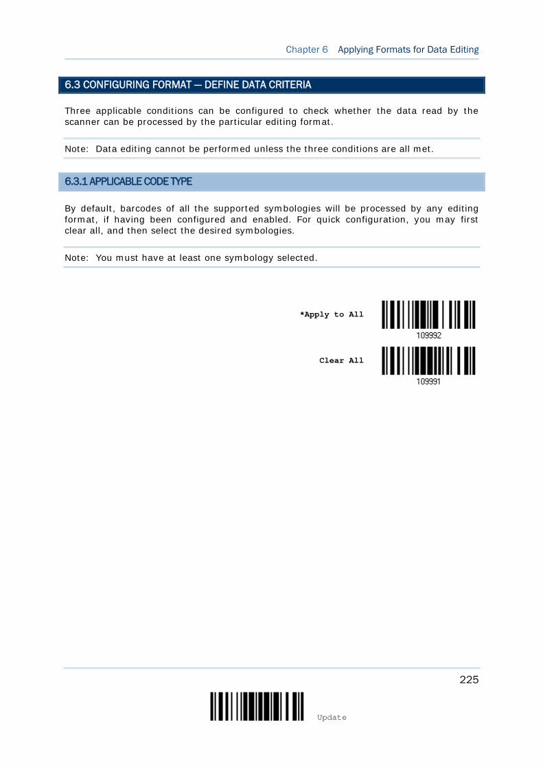
225
Update
Chapter 6 Applying Formats for Data Editing
6.3 CONFIGURING FORMAT — DEFINE DATA CRITERIA
Three applicable conditions can be configured to check whether the data read by the scanner can be processed by the particular editing format.
Note: Data editing cannot be performed unless the three conditions are all met.
6.3.1 APPLICABLE CODE TYPE
By default, barcodes of all the supported symbologies will be processed by any editing format, if having been configured and enabled. For quick configuration, you may first clear all, and then select the desired symbologies.
Note: You must have at least one symbology selected.
*Apply to All
Clear All
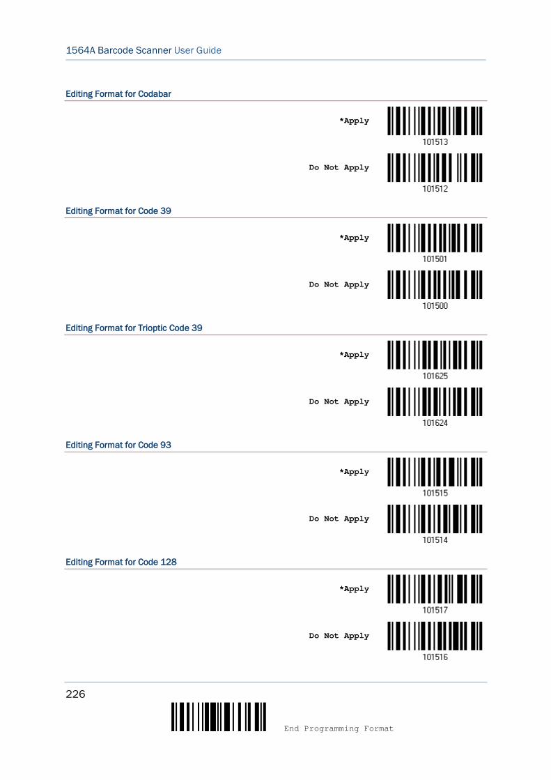
226
End Programming Format
1564A Barcode Scanner User Guide
Editing Format for Codabar
*Apply
Do Not Apply
Editing Format for Code 39
*Apply
Do Not Apply
Editing Format for Trioptic Code 39
*Apply
Do Not Apply
Editing Format for Code 93
*Apply
Do Not Apply
Editing Format for Code 128
*Apply
Do Not Apply
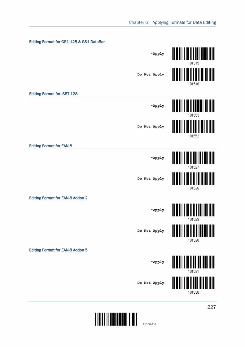
227
Update
Chapter 6 Applying Formats for Data Editing
Editing Format for GS1-128 & GS1 DataBar
*Apply
Do Not Apply
Editing Format for ISBT 128
*Apply
Do Not Apply
Editing Format for EAN-8
*Apply
Do Not Apply
Editing Format for EAN-8 Addon 2
*Apply
Do Not Apply
Editing Format for EAN-8 Addon 5
*Apply
Do Not Apply
228
End Programming Format
1564A Barcode Scanner User Guide
Editing Format for EAN-13
*Apply
Do Not Apply
Editing Format for EAN-13 Addon 2
*Apply
Do Not Apply
Editing Format for EAN-13 Addon 5
*Apply
Do Not Apply
Editing Format for Italian Pharmacode
*Apply
Do Not Apply
Editing Format for Industrial 25
*Apply
Do Not Apply
229
Update
Chapter 6 Applying Formats for Data Editing
Editing Format for Interleaved 25
*Apply
Do Not Apply
Editing Format for Matrix 25
*Apply
Do Not Apply
Editing Format for Chinese 25
*Apply
Do Not Apply
Editing Format for MSI
*Apply
Do Not Apply
Editing Format for UPC-A
*Apply
Do Not Apply

230
End Programming Format
1564A Barcode Scanner User Guide
Editing Format for UPC-A Addon 2
*Apply
Do Not Apply
Editing Format for UPC-A Addon 5
*Apply
Do Not Apply
Editing Format for UPC-E
*Apply
Do Not Apply
Editing Format for UPC-E Addon 2
*Apply
Do Not Apply
Editing Format for UPC-E Addon 5
*Apply
Do Not Apply

231
Update
Chapter 6 Applying Formats for Data Editing
Editing Format for UCC Coupon Extended Code
*Apply
Do Not Apply
Editing Format for Code 11
*Apply
Do Not Apply
Editing Format for Composite CC-A/B
*Apply
Do Not Apply
Editing Format for Composite CC-C
*Apply
Do Not Apply
Editing Format for Composite TLC-39
*Apply
Do Not Apply

232
End Programming Format
1564A Barcode Scanner User Guide
Editing Format for US Postnet
*Apply
Do Not Apply
Editing Format for US Planet
*Apply
Do Not Apply
Editing Format for UK Postal
*Apply
Do Not Apply
Editing Format for Japan Postal
*Apply
Do Not Apply
Editing Format for Australian Postal
*Apply
Do Not Apply
233
Update
Chapter 6 Applying Formats for Data Editing
Editing Format for Dutch Postal
*Apply
Do Not Apply
Editing Format for USPS 4CB/One Code/Intelligent Mail
*Apply
Do Not Apply
Editing Format for UPU FICS Postal
*Apply
Do Not Apply
Editing Format for PDF417
*Apply
Do Not Apply
Editing Format for MicroPDF417
*Apply
Do Not Apply
234
End Programming Format
1564A Barcode Scanner User Guide
Editing Format for Data Matrix
*Apply
Do Not Apply
Editing Format for Maxicode
*Apply
Do Not Apply
Editing Format for QR Code
*Apply
Do Not Apply
Editing Format for MicroQR
*Apply
Do Not Apply
Editing Format for Aztec
*Apply
Do Not Apply
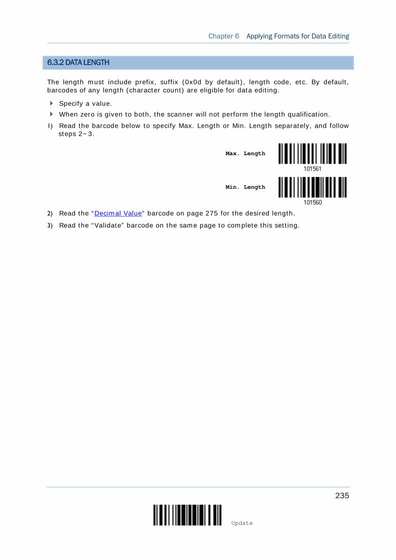
235
Update
Chapter 6 Applying Formats for Data Editing
6.3.2 DATA LENGTH
The length must include prefix, suffix (0x0d by default), length code, etc. By default, barcodes of any length (character count) are eligible for data editing.
Specify a value. When zero is given to both, the scanner will not perform the length qualification.
1) Read the barcode below to specify Max. Length or Min. Length separately, and follow steps 2~3.
Max. Length
Min. Length
2) Read the “Decimal Value” barcode on page 275 for the desired length.
3) Read the “Validate” barcode on the same page to complete this setting.
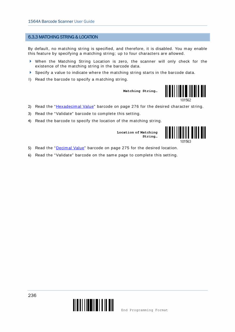
236
End Programming Format
1564A Barcode Scanner User Guide
6.3.3 MATCHING STRING & LOCATION
By default, no matching string is specified, and therefore, it is disabled. You may enable this feature by specifying a matching string; up to four characters are allowed.
When the Matching String Location is zero, the scanner will only check for the existence of the matching string in the barcode data.
Specify a value to indicate where the matching string starts in the barcode data.
1) Read the barcode to specify a matching string.
Matching String…
2) Read the “Hexadecimal Value” barcode on page 276 for the desired character string.
3) Read the “Validate” barcode to complete this setting.
4) Read the barcode to specify the location of the matching string.
Location of Matching String…
5) Read the “Decimal Value” barcode on page 275 for the desired location.
6) Read the “Validate” barcode on the same page to complete this setting.
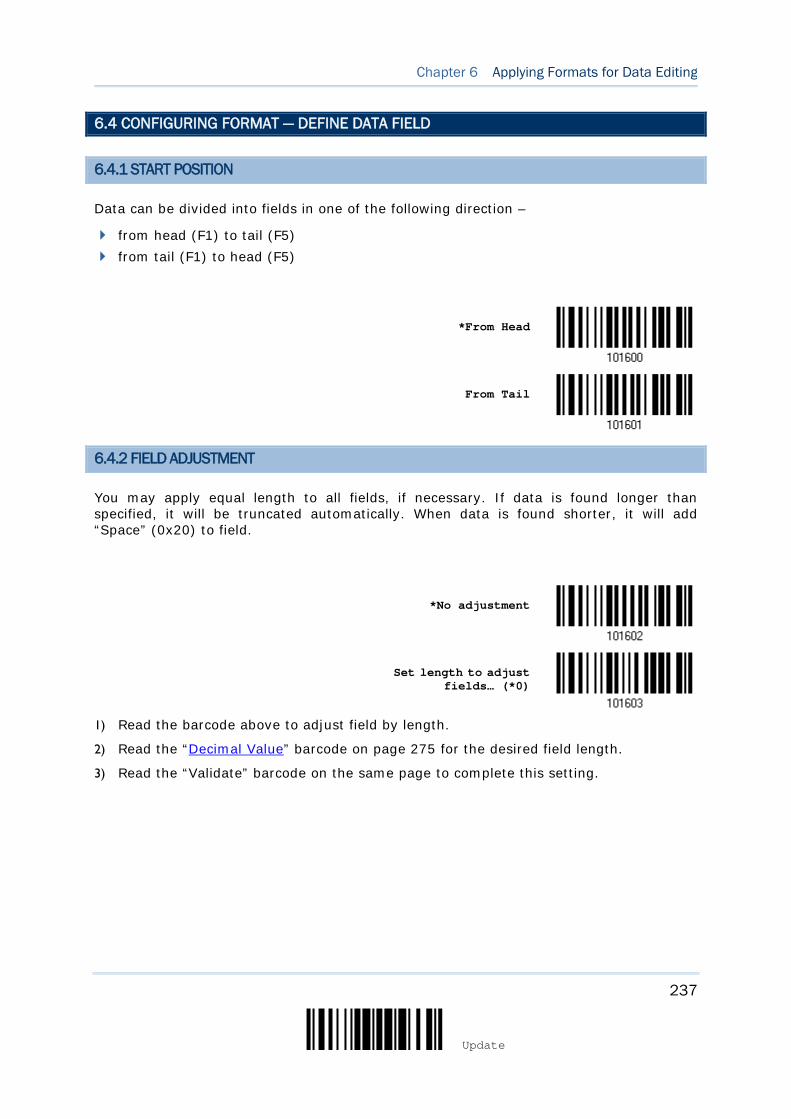
237
Update
Chapter 6 Applying Formats for Data Editing
6.4 CONFIGURING FORMAT — DEFINE DATA FIELD
6.4.1 START POSITION
Data can be divided into fields in one of the following direction –
from head (F1) to tail (F5) from tail (F1) to head (F5)
*From Head
From Tail
6.4.2 FIELD ADJUSTMENT
You may apply equal length to all fields, if necessary. If data is found longer than specified, it will be truncated automatically. When data is found shorter, it will add “Space” (0x20) to field.
*No adjustment
Set length to adjust fields… (*0)
1) Read the barcode above to adjust field by length.
2) Read the “Decimal Value” barcode on page 275 for the desired field length.
3) Read the “Validate” barcode on the same page to complete this setting.

238
End Programming Format
1564A Barcode Scanner User Guide
6.4.3 TOTAL NUMBER OF FIELDS
Data can be divided into at most 6 fields; each of them is numbered from F1 to F6 accordingly. However, only F1~F5 can be configured.
The total number of fields must be specified correctly. If three fields are configured for the editing format, the data characters after F3 will be assigned to F4 automatically. This feature is quite useful especially when data of variable lengths is processed by editing formats.
*One Field
Two Fields
Three Fields
Four Fields
Five Fields
Six Fields
Note: The number of configurable fields is always one less than the total number of fields specified. The extra data characters beyond the last field configured will be automatically assigned to the next field.
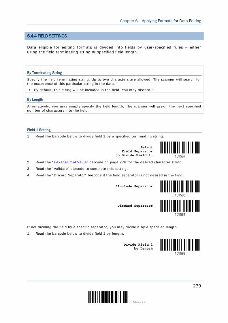
239
Update
Chapter 6 Applying Formats for Data Editing
6.4.4 FIELD SETTINGS
Data eligible for editing formats is divided into fields by user-specified rules – either using the field terminating string or specified field length.
By Terminating String
Specify the field terminating string. Up to two characters are allowed. The scanner will search for the occurrence of this particular string in the data.
By default, this string will be included in the field. You may discard it.
By Length
Alternatively, you may simply specify the field length. The scanner will assign the next specified number of characters into the field.
Field 1 Setting
1. Read the barcode below to divide field 1 by a specified terminating string.
Select Field Separator
to Divide Field 1…
2. Read the “Hexadecimal Value” barcode on page 276 for the desired character string.
3. Read the “Validate” barcode to complete this setting.
4. Read the “Discard Separator” barcode if the field separator is not desired in the field.
*Include Separator
Discard Separator
If not dividing the field by a specific separator, you may divide it by a specified length.
1. Read the barcode below to divide field 1 by length.
Divide Field 1 by Length

240
End Programming Format
1564A Barcode Scanner User Guide
2. Read the “Decimal Value” barcode on page 275 for the desired field length.
3. Read the “Validate” barcode on the same page to complete this setting.
Field 2 Setting
1. Read the barcode below to divide field 2 by a specified terminating string.
Select Field Separator
to Divide Field 2…
2. Read the “Hexadecimal Value” barcode on page 276 for the desired character string.
3. Read the “Validate” barcode to complete this setting.
4. Read the “Discard Separator” barcode if the field separator is not desired in the field.
*Include Separator
Discard Separator
If not dividing the field by a specific separator, you may divide it by a specified length.
1. Read the barcode below to divide field 2 by length.
Divide Field 2 by Length
2. Read the “Decimal Value” barcode on page 275 for the desired field length.
3. Read the “Validate” barcode on the same page to complete this setting.
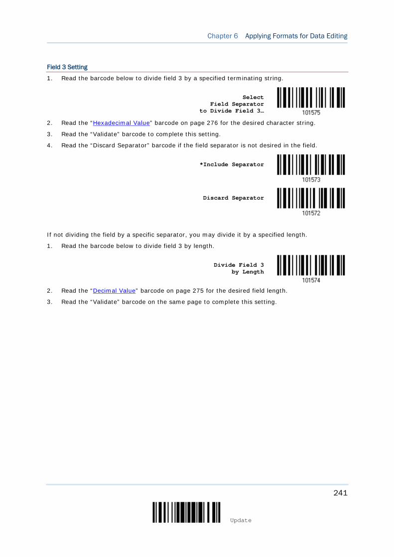
241
Update
Chapter 6 Applying Formats for Data Editing
Field 3 Setting
1. Read the barcode below to divide field 3 by a specified terminating string.
Select Field Separator
to Divide Field 3…
2. Read the “Hexadecimal Value” barcode on page 276 for the desired character string.
3. Read the “Validate” barcode to complete this setting.
4. Read the “Discard Separator” barcode if the field separator is not desired in the field.
*Include Separator
Discard Separator
If not dividing the field by a specific separator, you may divide it by a specified length.
1. Read the barcode below to divide field 3 by length.
Divide Field 3 by Length
2. Read the “Decimal Value” barcode on page 275 for the desired field length.
3. Read the “Validate” barcode on the same page to complete this setting.

242
End Programming Format
1564A Barcode Scanner User Guide
Field 4 Setting
1. Read the barcode below to divide field 4 by a specified terminating string.
Select Field Separator
to Divide Field 4…
2. Read the “Hexadecimal Value” barcode on page 276 for the desired character string.
3. Read the “Validate” barcode to complete this setting.
4. Read the “Discard Separator” barcode if the field separator is not desired in the field.
*Include Separator
Discard Separator
If not dividing the field by a specific separator, you may divide it by a specified length.
1. Read the barcode below to divide field 4 by length.
Divide Field 4 by Length
2. Read the “Decimal Value” barcode on page 275 for the desired field length.
3. Read the “Validate” barcode on the same page to complete this setting.
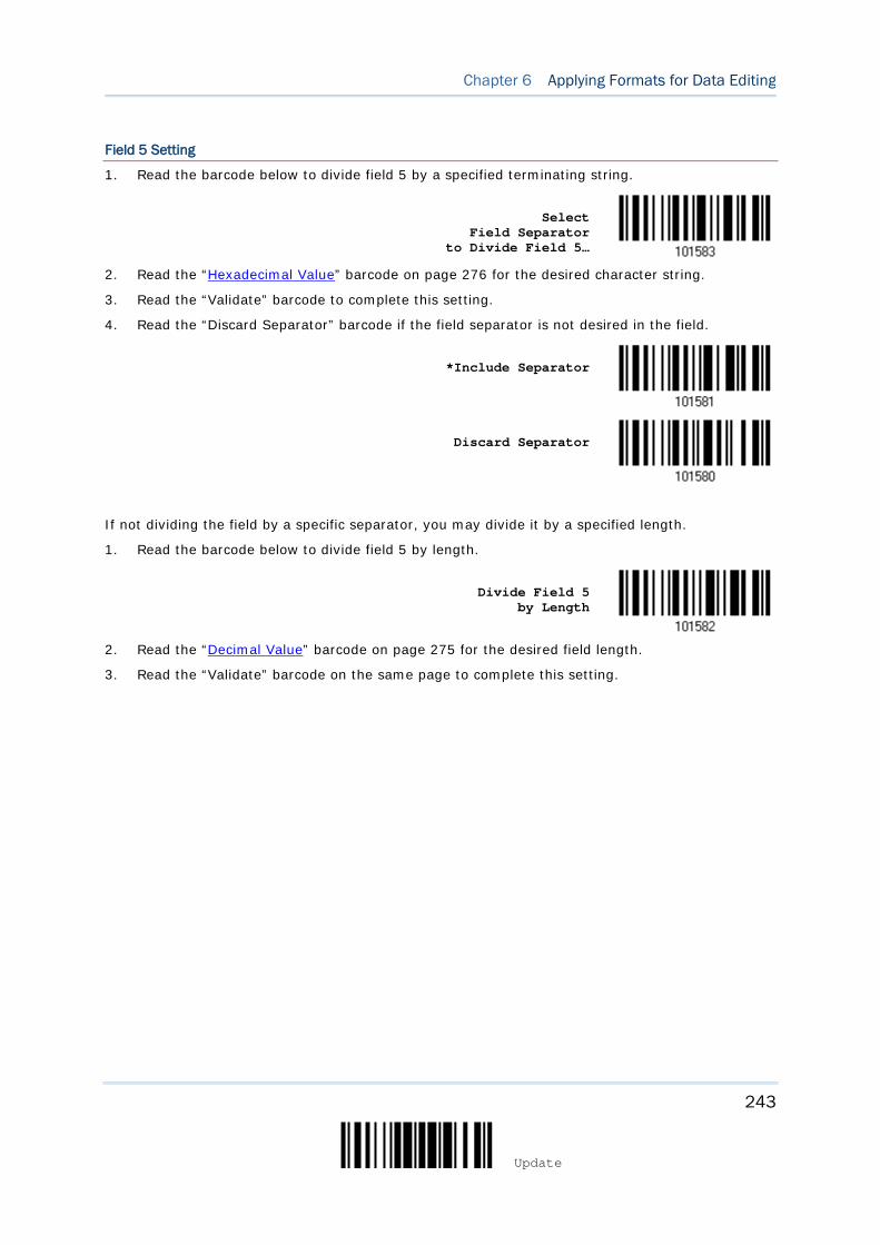
243
Update
Chapter 6 Applying Formats for Data Editing
Field 5 Setting
1. Read the barcode below to divide field 5 by a specified terminating string.
Select Field Separator
to Divide Field 5…
2. Read the “Hexadecimal Value” barcode on page 276 for the desired character string.
3. Read the “Validate” barcode to complete this setting.
4. Read the “Discard Separator” barcode if the field separator is not desired in the field.
*Include Separator
Discard Separator
If not dividing the field by a specific separator, you may divide it by a specified length.
1. Read the barcode below to divide field 5 by length.
Divide Field 5 by Length
2. Read the “Decimal Value” barcode on page 275 for the desired field length.
3. Read the “Validate” barcode on the same page to complete this setting.
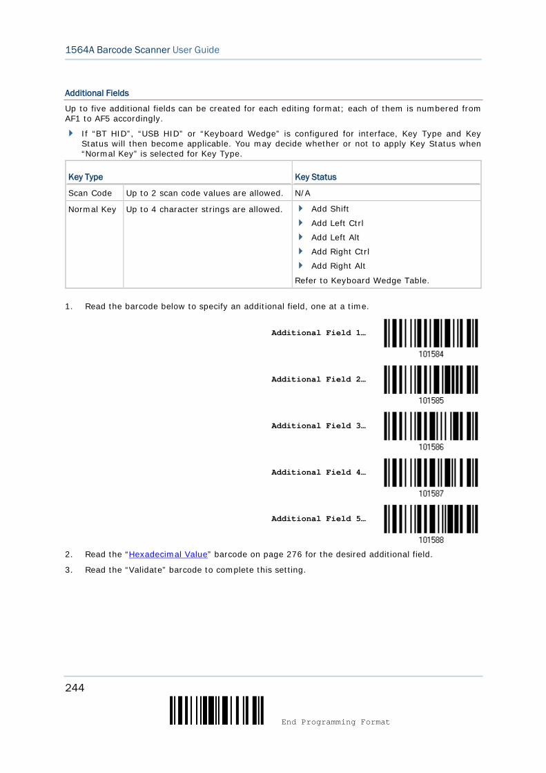
244
End Programming Format
1564A Barcode Scanner User Guide
Additional Fields
Up to five additional fields can be created for each editing format; each of them is numbered from AF1 to AF5 accordingly.
If “BT HID”, “USB HID” or “Keyboard Wedge” is configured for interface, Key Type and Key Status will then become applicable. You may decide whether or not to apply Key Status when “Normal Key” is selected for Key Type.
Key Type Key Status
Scan Code Up to 2 scan code values are allowed. N/A
Normal Key Up to 4 character strings are allowed. Add Shift
Add Left Ctrl
Add Left Alt
Add Right Ctrl
Add Right Alt
Refer to Keyboard Wedge Table.
1. Read the barcode below to specify an additional field, one at a time.
Additional Field 1…
Additional Field 2…
Additional Field 3…
Additional Field 4…
Additional Field 5…
2. Read the “Hexadecimal Value” barcode on page 276 for the desired additional field.
3. Read the “Validate” barcode to complete this setting.
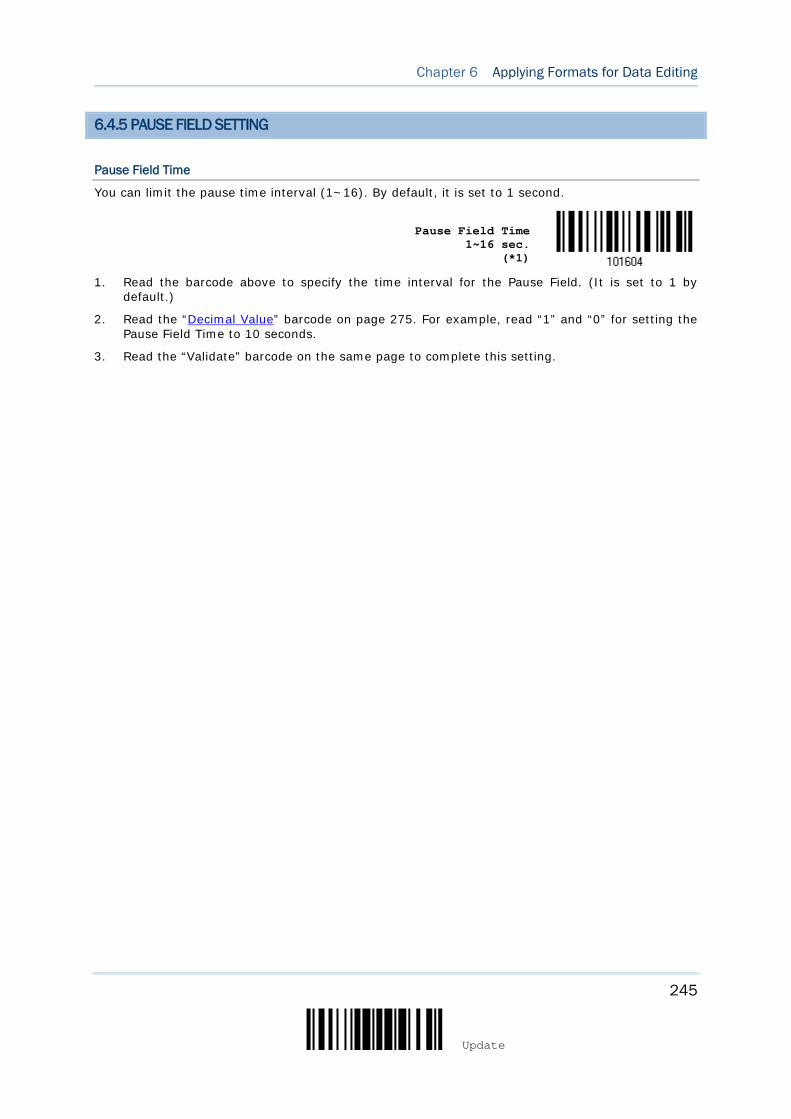
245
Update
Chapter 6 Applying Formats for Data Editing
6.4.5 PAUSE FIELD SETTING
Pause Field Time
You can limit the pause time interval (1~16). By default, it is set to 1 second.
Pause Field Time 1~16 sec.
(*1)
1. Read the barcode above to specify the time interval for the Pause Field. (It is set to 1 by default.)
2. Read the “Decimal Value” barcode on page 275. For example, read “1” and “0” for setting the Pause Field Time to 10 seconds.
3. Read the “Validate” barcode on the same page to complete this setting.

246
End Programming Format
1564A Barcode Scanner User Guide
6.5 CONFIGURING FORMAT — DEFINE TRANSMISSION SEQUENCE
After configuring the data fields and additional fields, you must now program the transmission sequence of these fields that comprise the final data. This field transmission sequence can be assigned in any desired order and fields can be assigned multiple times as well.
Note: Up to twelve fields can be assigned.
1) Read the “Start” barcode to begin with programming the field transmission sequence.
Start Programming…
2) Program the transmission sequence by reading the desired fields as well as additional
fields.
Field 1
Field 2
Field 3
Field 4
Field 5
Field 6
Additional Field 1
Additional Field 2
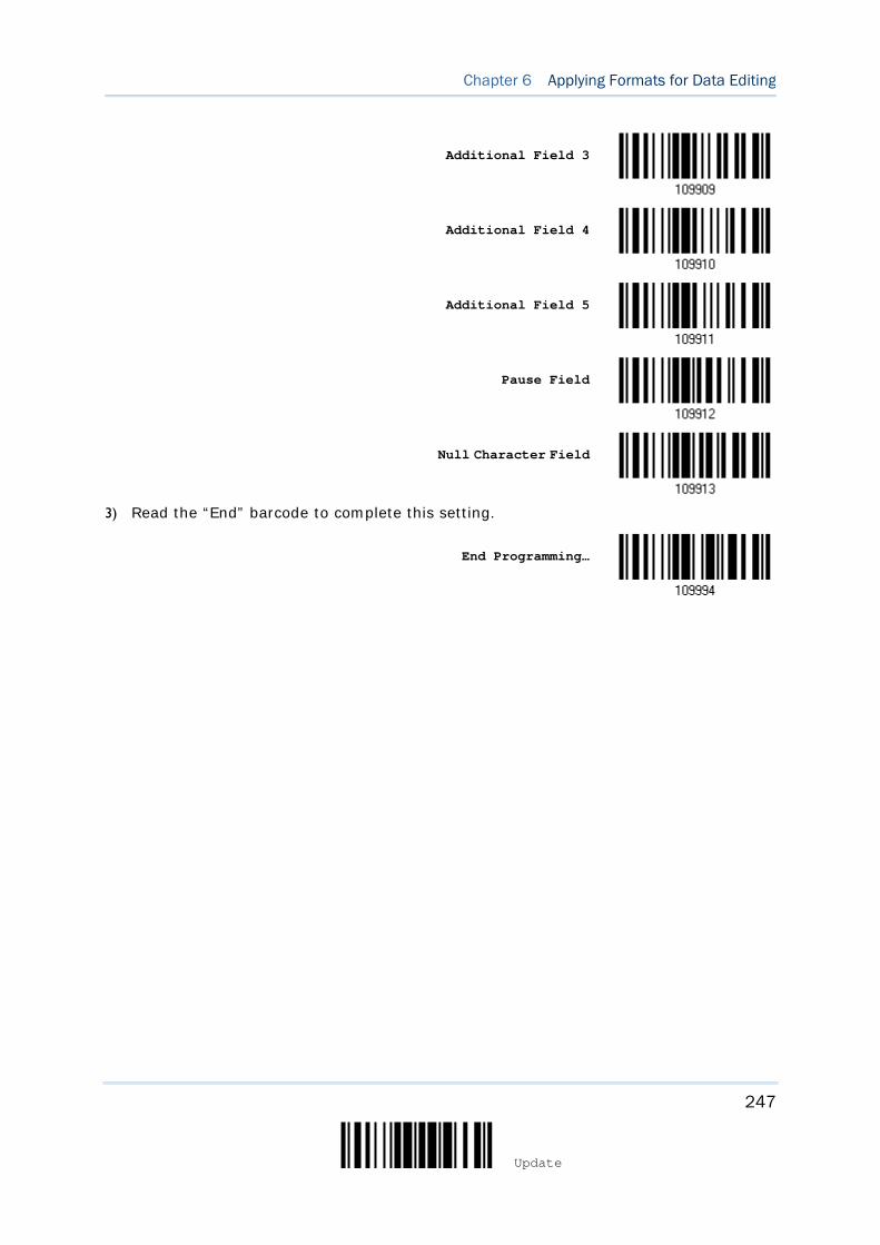
247
Update
Chapter 6 Applying Formats for Data Editing
Additional Field 3
Additional Field 4
Additional Field 5
Pause Field
Null Character Field
3) Read the “End” barcode to complete this setting.
End Programming…
248
End Programming Format
1564A Barcode Scanner User Guide
6.6 PROGRAMMING EXAMPLES
6.6.1 EXAMPLE I
Extract data from the 10th character to the 19th character...
The editing format should be configured as follows:
1. Read the “Enter Setup” barcode to enter the Configuration Mode.
2. Read the “Configure Format 1” barcode.
3. Read the “Clear All” and “Code 128” barcodes for applicable code type.
4. Read the “Three Fields” barcode.
5. Read the “Divide Field 1 by Length” barcode, and set length to 9.
Field 1 data starts from the 1st character to the 9th character.
6. Read the “Divide Field 2 by Length” barcode, and set length to 10.
Field 2 data starts from the 10th character to the 19th character.
7. Read the “Start (Programming)” barcode to program the transmission sequence.
8. Read the “Field 2” barcode.
9. Read the “End” barcode to complete the transmission sequence setting.
10. Read the “End Programming Format” barcode to complete the setting of Editing Format 1.
11. Read the “Enable Format 1” barcode to apply Editing Format 1 to Code 128.
12. Read the “Update” barcode to exit the Configuration Mode.
249
Update
Chapter 6 Applying Formats for Data Editing
6.6.2 EXAMPLE II
Extract the date code, item number, and quantity information from barcodes.
Data in a barcode is encoded like this:
From the 1st character to the 6th character is the date code.
From the 7th character to the dash ‘-’ character is the item number.
After the dash ‘-’ character is the quantity information.
Data will be transmitted like this:
The item number goes first, then a TAB character, followed by the date code, then another TAB character, and finally the quantity information.
The editing format should be configured as follows:
1. Read the “Enter Setup” barcode to enter the Configuration Mode.
2. Read the “Configure Format 2” barcode.
3. Read the “Three Fields” barcode.
4. Read the “Divide Field 1 by Length” barcode, and set length to 6.
Field 1 data starts from the 1st character to the 6th character.
5. Read the “Select Field Separator to Divide Field 2” barcode, and use a dash ‘-’ character.
Field 2 data starts from the 7th character until the dash ‘-’ character is met.
6. Read the “Additional Field 1” barcode, and use a tab character for the field.
7. Read the “Start (Programming)” barcode to program the transmission sequence.
8. Read the “Field 2”, “Additional Field 1”, “Field 1”, “Additional Field 1”, “Field 3” barcodes.
9. Read the “End” barcode to complete the transmission sequence (F2 A1 F1 A1 F3) setting.
10. Read the “End Programming Format” barcode to complete the setting of Editing Format 1.
11. Read the “Enable Format 2” barcode to apply Editing Format 2 to all code types.
12. Read the “Update” barcode to exit the Configuration Mode.

250
End Programming Format
1564A Barcode Scanner User Guide
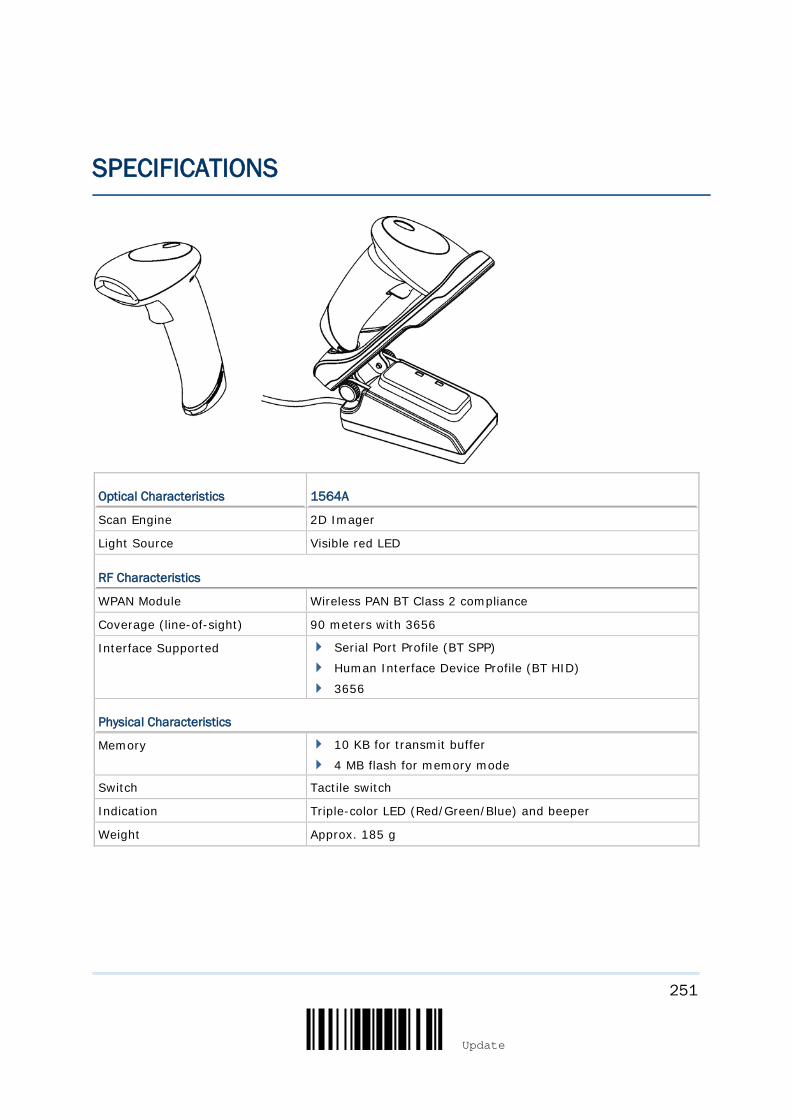
251
Update
Optical Characteristics 1564A
Scan Engine 2D Imager
Light Source Visible red LED
RF Characteristics
WPAN Module Wireless PAN BT Class 2 compliance
Coverage (line-of-sight) 90 meters with 3656
Interface Supported Serial Port Profile (BT SPP)
Human Interface Device Profile (BT HID)
3656
Physical Characteristics
Memory 10 KB for transmit buffer
4 MB flash for memory mode
Switch Tactile switch
Indication Triple-color LED (Red/Green/Blue) and beeper
Weight Approx. 185 g
SPECIFICATIONS
252
Enter Setup
1564A Barcode Scanner User Guide
Electrical Characteristics
Battery Rechargeable Li-ion battery – 3.7 V, 800 mAh
Power Adaptor
Input AC 100~240 V, 50/60 Hz
Output DC 5V, 2A (3656)
DC 5V, 0.5A (Battery Charger)
Operating Temperature 0 °C to 40 °C
Environmental Characteristics
Temperature Operating
Storage
0 °C to 50 °C
-20 °C to 60 °C
Humidity (Non-condensing)
Operating
Storage
10% to 90%
5% to 95%
Resistance
Impact Resistance 1.2 m, 5 drops per 6 sides
Splash / Dust Resistance IP 30
Electrostatic Discharge ± 15 kV air discharge, ± 8 kV contact discharge
Programming Support
Configuration Setup barcodes or host serial commands.
Software Windows®-based ScanMaster
Firmware upgradeable Download firmware updates via the download utility.
Accessories (√ means “supported”)
Rechargeable Li-ion Battery √
Battery Charger √
3656 Stand √
USB Cable √
RS-232 Cable √
Keyboard Wedge Cable √
Note: The 3656 stand is not only capable of charging the scanner, but specifically designed for the scanner to communicate with a host computer wirelessly.
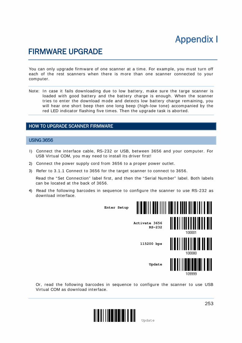
253
Update
You can only upgrade firmware of one scanner at a time. For example, you must turn off each of the rest scanners when there is more than one scanner connected to your computer.
Note: In case it fails downloading due to low battery, make sure the targe scanner is loaded with good battery and the battery charge is enough. When the scanner tries to enter the download mode and detects low battery charge remaining, you will hear one short beep then one long beep (high-low tone) accompanied by the red LED indicator flashing five times. Then the upgrade task is aborted.
HOW TO UPGRADE SCANNER FIRMWARE
USING 3656
1) Connect the interface cable, RS-232 or USB, between 3656 and your computer. For USB Virtual COM, you may need to install its driver first!
2) Connect the power supply cord from 3656 to a proper power outlet.
3) Refer to 3.1.1 Connect to 3656 for the target scanner to connect to 3656.
Read the “Set Connection” label first, and then the “Serial Number” label. Both labels can be located at the back of 3656.
4) Read the following barcodes in sequence to configure the scanner to use RS-232 as download interface.
Enter Setup
Activate 3656 RS-232
115200 bps
Update
Or, read the following barcodes in sequence to configure the scanner to use USB Virtual COM as download interface.
Appendix I FIRMWARE UPGRADE
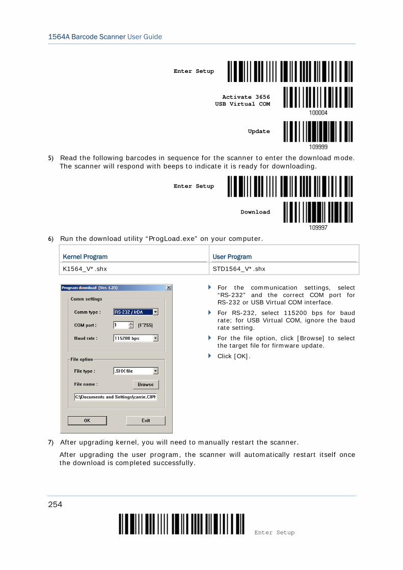
254
Enter Setup
1564A Barcode Scanner User Guide
Enter Setup
Activate 3656 USB Virtual COM
Update
5) Read the following barcodes in sequence for the scanner to enter the download mode.
The scanner will respond with beeps to indicate it is ready for downloading.
Enter Setup
Download
6) Run the download utility “ProgLoad.exe” on your computer.
Kernel Program User Program
K1564_V*.shx STD1564_V*.shx
For the communication settings, select “RS-232” and the correct COM port for RS-232 or USB Virtual COM interface.
For RS-232, select 115200 bps for baud rate; for USB Virtual COM, ignore the baud rate setting.
For the file option, click [Browse] to select the target file for firmware update.
Click [OK].
7) After upgrading kernel, you will need to manually restart the scanner.
After upgrading the user program, the scanner will automatically restart itself once the download is completed successfully.
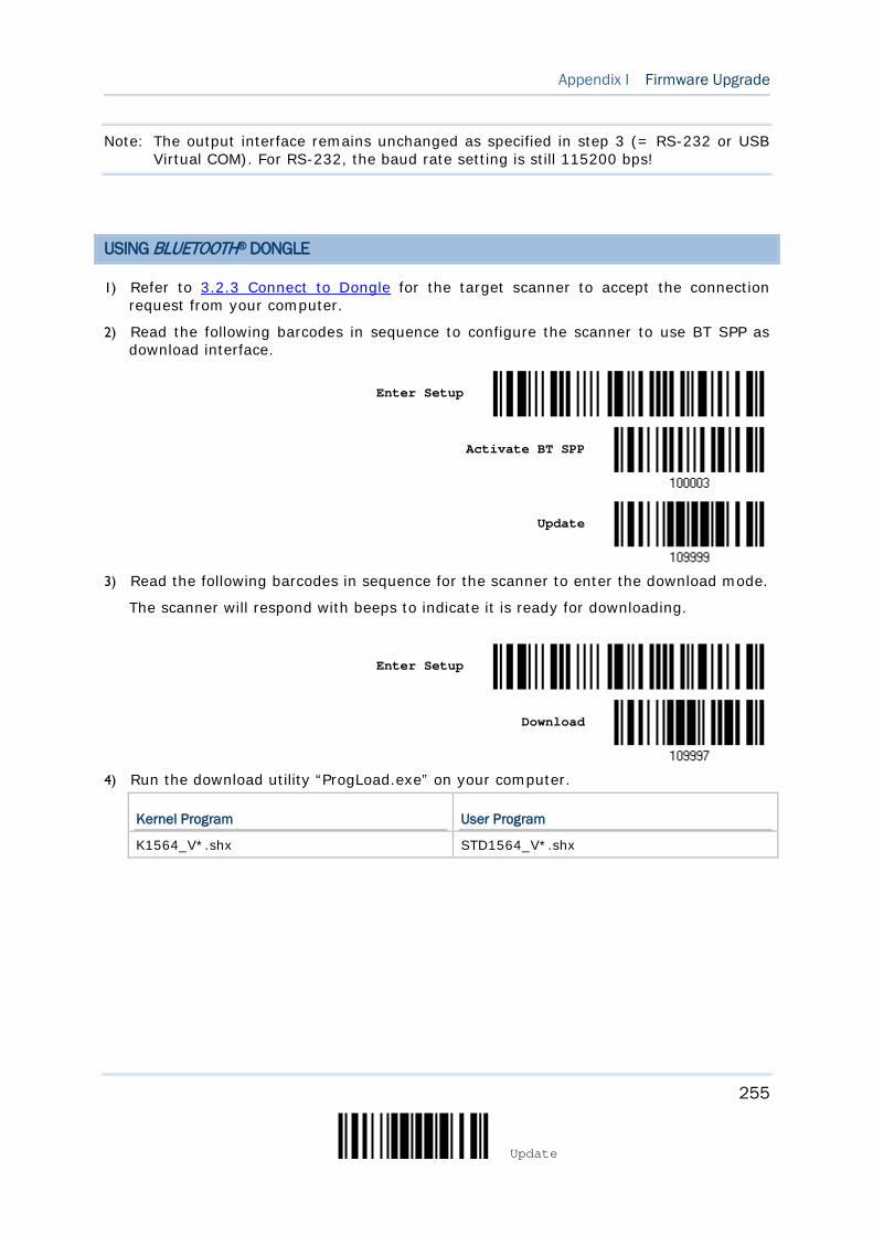
255
Update
Appendix I Firmware Upgrade
Note: The output interface remains unchanged as specified in step 3 (= RS-232 or USB Virtual COM). For RS-232, the baud rate setting is still 115200 bps!
USING BLUETOOTH® DONGLE
1) Refer to 3.2.3 Connect to Dongle for the target scanner to accept the connection request from your computer.
2) Read the following barcodes in sequence to configure the scanner to use BT SPP as download interface.
Enter Setup
Activate BT SPP
Update
3) Read the following barcodes in sequence for the scanner to enter the download mode.
The scanner will respond with beeps to indicate it is ready for downloading.
Enter Setup
Download
4) Run the download utility “ProgLoad.exe” on your computer.
Kernel Program User Program
K1564_V*.shx STD1564_V*.shx
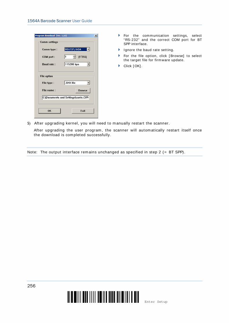
256
Enter Setup
1564A Barcode Scanner User Guide
For the communication settings, select “RS-232” and the correct COM port for BT SPP interface.
Ignore the baud rate setting.
For the file option, click [Browse] to select the target file for firmware update.
Click [OK].
5) After upgrading kernel, you will need to manually restart the scanner.
After upgrading the user program, the scanner will automatically restart itself once the download is completed successfully.
Note: The output interface remains unchanged as specified in step 2 (= BT SPP).
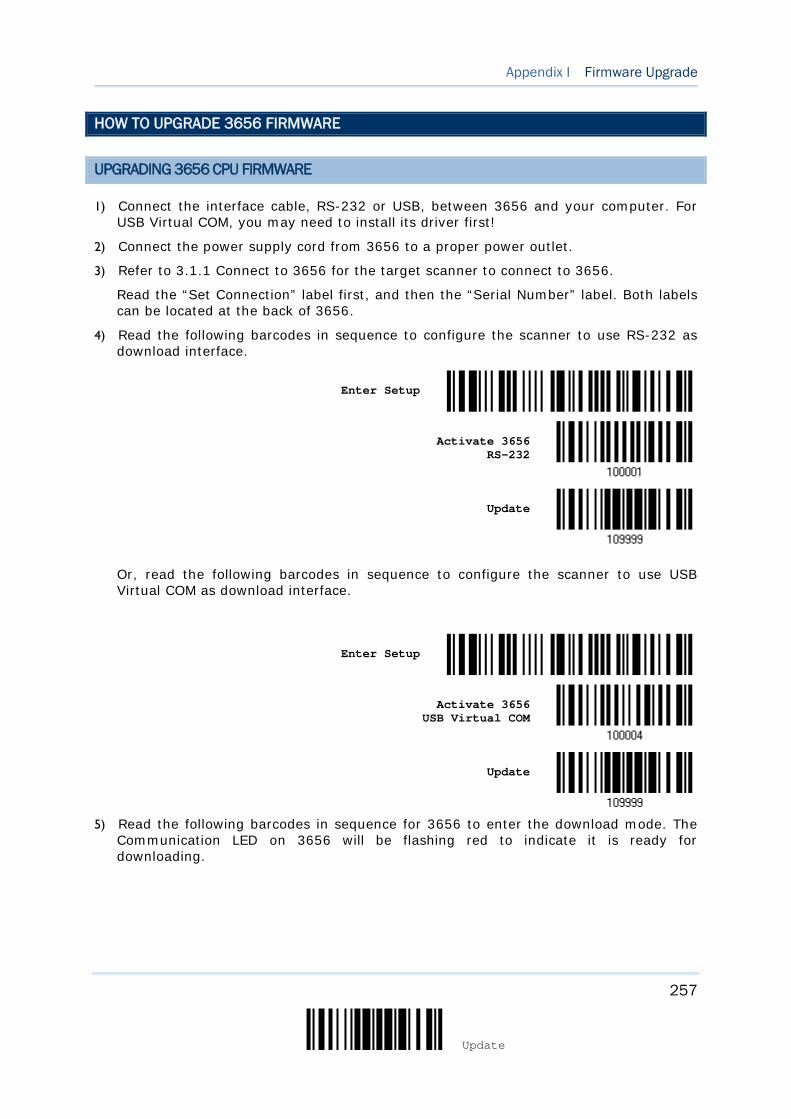
257
Update
Appendix I Firmware Upgrade
HOW TO UPGRADE 3656 FIRMWARE
UPGRADING 3656 CPU FIRMWARE
1) Connect the interface cable, RS-232 or USB, between 3656 and your computer. For USB Virtual COM, you may need to install its driver first!
2) Connect the power supply cord from 3656 to a proper power outlet.
3) Refer to 3.1.1 Connect to 3656 for the target scanner to connect to 3656.
Read the “Set Connection” label first, and then the “Serial Number” label. Both labels can be located at the back of 3656.
4) Read the following barcodes in sequence to configure the scanner to use RS-232 as download interface.
Enter Setup
Activate 3656 RS-232
Update
Or, read the following barcodes in sequence to configure the scanner to use USB Virtual COM as download interface.
Enter Setup
Activate 3656 USB Virtual COM
Update
5) Read the following barcodes in sequence for 3656 to enter the download mode. The
Communication LED on 3656 will be flashing red to indicate it is ready for downloading.
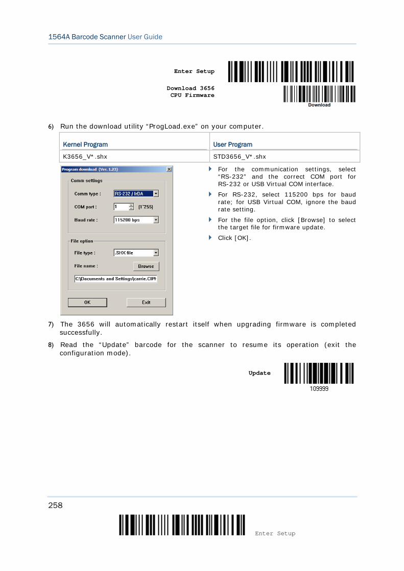
258
Enter Setup
1564A Barcode Scanner User Guide
Enter Setup
Download 3656
CPU Firmware
6) Run the download utility “ProgLoad.exe” on your computer.
Kernel Program User Program
K3656_V*.shx STD3656_V*.shx
For the communication settings, select “RS-232” and the correct COM port for RS-232 or USB Virtual COM interface.
For RS-232, select 115200 bps for baud rate; for USB Virtual COM, ignore the baud rate setting.
For the file option, click [Browse] to select the target file for firmware update.
Click [OK].
7) The 3656 will automatically restart itself when upgrading firmware is completed successfully.
8) Read the “Update” barcode for the scanner to resume its operation (exit the configuration mode).
Update

259
Update
Appendix I Firmware Upgrade
UPGRADING 3656 USB BRIDGE FIRMWARE
1) Connect the USB cable between 3656 and your computer. For USB Virtual COM, you may need to install its driver first!
2) Connect the power supply cord from 3656 to a proper power outlet.
3) Refer to 3.1.1 Connect to 3656 for the target scanner to connect to 3656.
Read the “Set Connection” label first, and then the “Serial Number” label. Both labels can be located at the back of 3656.
4) Read the following barcodes in sequence to configure the scanner to use USB Virtual COM as download interface.
Enter Setup
Activate 3656 USB Virtual COM
Update
Note: You can download USB Bridge firmware via USB Virtual COM only!
5) Read the following barcodes in sequence for 3656 to enter the download mode. The Communication LED on 3656 will be flashing red to indicate it is ready for downloading.
Enter Setup
Download 3656
USB Bridge Firmware
6) Run the download utility “ProgLoad.exe” on your computer.
Kernel Program User Program
K3656Bridge_V*.shx STD3656Bridge_V*.shx
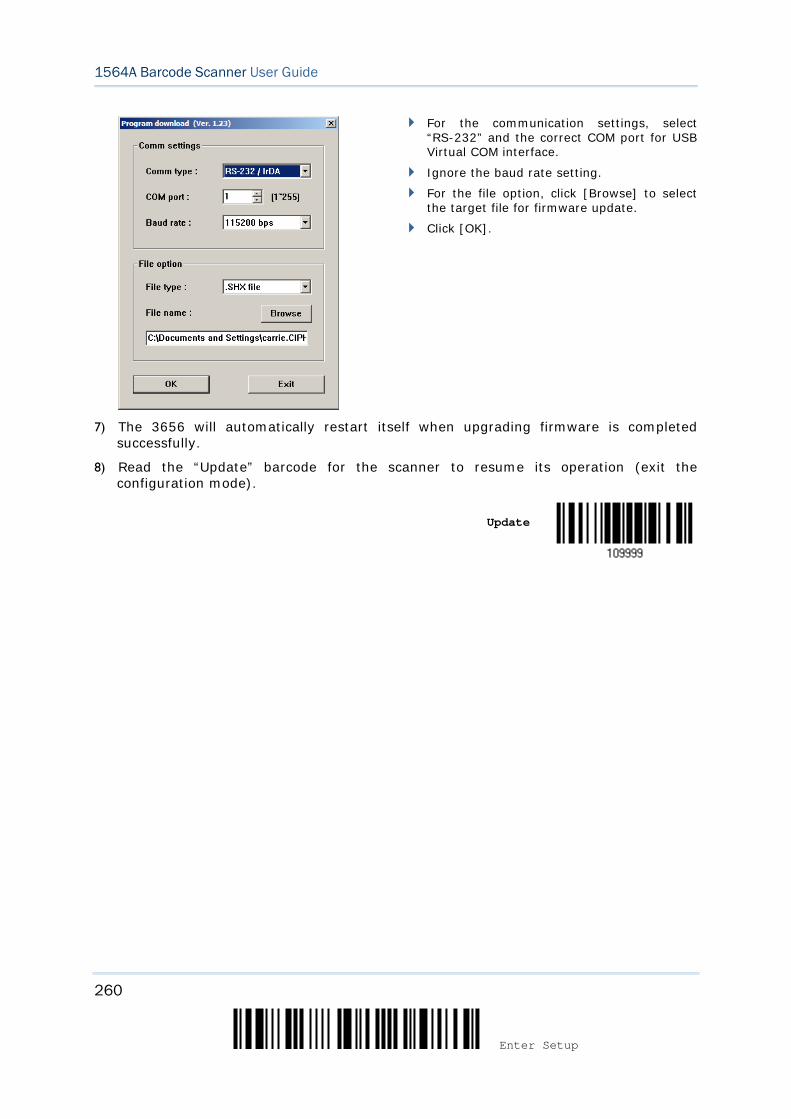
260
Enter Setup
1564A Barcode Scanner User Guide
For the communication settings, select “RS-232” and the correct COM port for USB Virtual COM interface.
Ignore the baud rate setting.
For the file option, click [Browse] to select the target file for firmware update.
Click [OK].
7) The 3656 will automatically restart itself when upgrading firmware is completed successfully.
8) Read the “Update” barcode for the scanner to resume its operation (exit the configuration mode).
Update
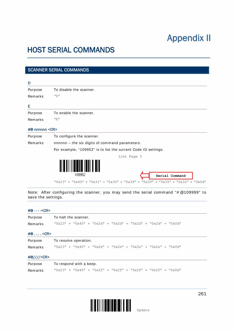
261
Update
SCANNER SERIAL COMMANDS
D
Purpose To disable the scanner.
Remarks “D”
E
Purpose To enable the scanner.
Remarks “E”
#@ nnnnnn <CR>
Purpose To configure the scanner.
Remarks nnnnnn – the six digits of command parameters.
For example, “109952” is to list the current Code ID settings.
“0x23” + “0x40” + “0x31” + “0x30” + “0x39” + “0x39” + “0x35” + “0x32” + “0x0d”
Note: After configuring the scanner, you may send the serial command “#@109999” to save the settings.
#@ - - - -<CR>
Purpose To halt the scanner.
Remarks “0x23” + “0x40” + “0x2d” + “0x2d” + “0x2d” + “0x2d” + “0x0d”
#@ . . . . <CR>
Purpose To resume operation.
Remarks “0x23” + “0x40” + “0x2e” + “0x2e” + “0x2e” + “0x2e” + “0x0d”
#@////<CR>
Purpose To respond with a beep.
Remarks “0x23” + “0x40” + “0x2f” + “0x2f” + “0x2f” + “0x2f” + “0x0d”
Appendix II HOST SERIAL COMMANDS
Serial Command
List Page 3
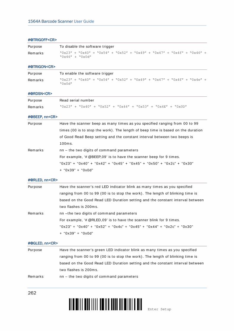
262
Enter Setup
1564A Barcode Scanner User Guide
#@TRIGOFF<CR>
Purpose To disable the software trigger
Remarks “0x23” + “0x40” + “0x54” + “0x52” + “0x49” + “0x47” + “0x4f” + “0x46” + “0x46” + “0x0d”
#@TRIGON<CR>
Purpose To enable the software trigger
Remarks “0x23” + “0x40” + “0x54” + “0x52” + “0x49” + “0x47” + “0x4f” + “0x4e” + “0x0d”
#@RDSN<CR>
Purpose Read serial number
Remarks “0x23” + “0x40” + “0x52” + “0x44” + “0x53” + “0x4E” + “0x0D”
#@BEEP, nn<CR>
Purpose Have the scanner beep as many times as you specified ranging from 00 to 99
times (00 is to stop the work). The length of beep time is based on the duration
of Good Read Beep setting and the constant interval between two beeps is
100ms.
Remarks nn – the two digits of command parameters
For example, ‘#@BEEP,09’ is to have the scanner beep for 9 times.
“0x23” + “0x40” + “0x42” + “0x45” + “0x45” + “0x50” + “0x2c” + “0x30”
+ “0x39” + “0x0d”
#@RLED, nn<CR>
Purpose Have the scanner’s red LED indicator blink as many times as you specified
ranging from 00 to 99 (00 is to stop the work). The length of blinking time is
based on the Good Read LED Duration setting and the constant interval between
two flashes is 200ms.
Remarks nn –the two digits of command parameters
For example, ‘#@RLED,09’ is to have the scanner blink for 9 times.
“0x23” + “0x40” + “0x52” + “0x4c” + “0x45” + “0x44” + “0x2c” + “0x30”
+ “0x39” + “0x0d”
#@GLED, nn<CR>
Purpose Have the scanner’s green LED indicator blink as many times as you specified
ranging from 00 to 99 (00 is to stop the work). The length of blinking time is
based on the Good Read LED Duration setting and the constant interval between
two flashes is 200ms.
Remarks nn – the two digits of command parameters
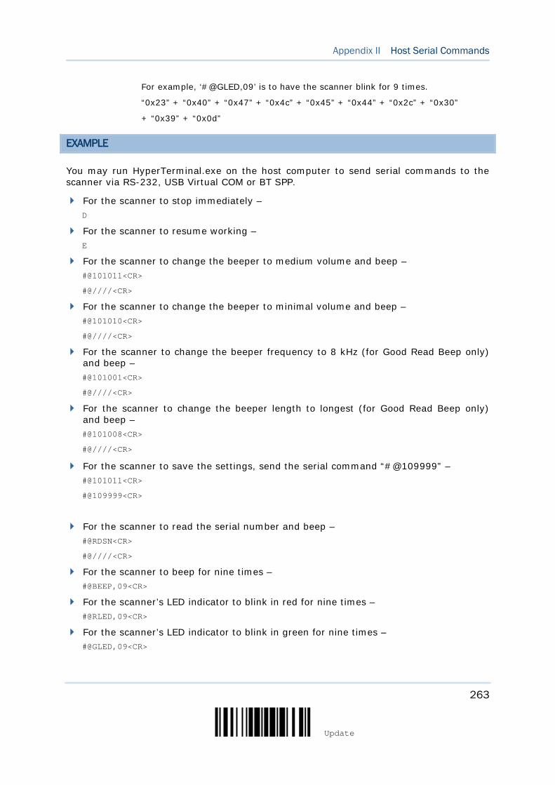
263
Update
Appendix II Host Serial Commands
For example, ‘#@GLED,09’ is to have the scanner blink for 9 times.
“0x23” + “0x40” + “0x47” + “0x4c” + “0x45” + “0x44” + “0x2c” + “0x30”
+ “0x39” + “0x0d”
EXAMPLE
You may run HyperTerminal.exe on the host computer to send serial commands to the scanner via RS-232, USB Virtual COM or BT SPP.
For the scanner to stop immediately – D
For the scanner to resume working – E
For the scanner to change the beeper to medium volume and beep – #@101011<CR>
#@////<CR>
For the scanner to change the beeper to minimal volume and beep – #@101010<CR>
#@////<CR>
For the scanner to change the beeper frequency to 8 kHz (for Good Read Beep only) and beep – #@101001<CR>
#@////<CR>
For the scanner to change the beeper length to longest (for Good Read Beep only) and beep – #@101008<CR>
#@////<CR>
For the scanner to save the settings, send the serial command “#@109999” – #@101011<CR>
#@109999<CR>
For the scanner to read the serial number and beep – #@RDSN<CR>
#@////<CR>
For the scanner to beep for nine times – #@BEEP,09<CR>
For the scanner’s LED indicator to blink in red for nine times – #@RLED,09<CR>
For the scanner’s LED indicator to blink in green for nine times – #@GLED,09<CR>

264
Enter Setup
1564A Barcode Scanner User Guide
Note: (1) For RS-232 or USB Virtual COM, you can only configure the first scanner that connects to 3656. To identify the scanner, you may send the serial command to have it respond with a beep. (2) For BT SPP, you can configure up to seven scanners at the same time.
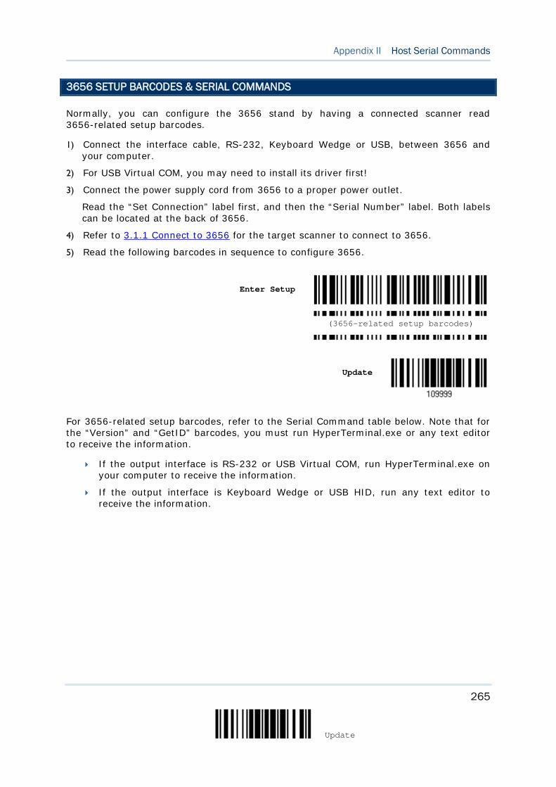
265
Update
Appendix II Host Serial Commands
3656 SETUP BARCODES & SERIAL COMMANDS
Normally, you can configure the 3656 stand by having a connected scanner read 3656-related setup barcodes.
1) Connect the interface cable, RS-232, Keyboard Wedge or USB, between 3656 and your computer.
2) For USB Virtual COM, you may need to install its driver first!
3) Connect the power supply cord from 3656 to a proper power outlet.
Read the “Set Connection” label first, and then the “Serial Number” label. Both labels can be located at the back of 3656.
4) Refer to 3.1.1 Connect to 3656 for the target scanner to connect to 3656.
5) Read the following barcodes in sequence to configure 3656.
Enter Setup
Update
For 3656-related setup barcodes, refer to the Serial Command table below. Note that for the “Version” and “GetID” barcodes, you must run HyperTerminal.exe or any text editor to receive the information.
If the output interface is RS-232 or USB Virtual COM, run HyperTerminal.exe on your computer to receive the information.
If the output interface is Keyboard Wedge or USB HID, run any text editor to receive the information.
(3656-related setup barcodes)
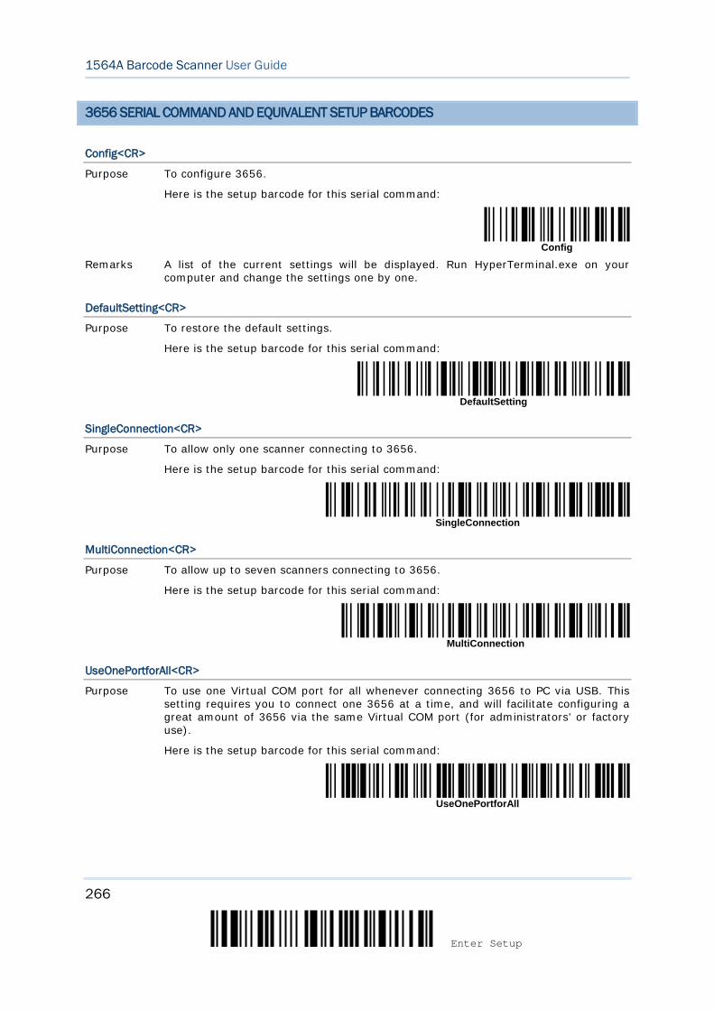
266
Enter Setup
1564A Barcode Scanner User Guide
3656 SERIAL COMMAND AND EQUIVALENT SETUP BARCODES
Config<CR>
Purpose To configure 3656.
Here is the setup barcode for this serial command:
Config Remarks A list of the current settings will be displayed. Run HyperTerminal.exe on your
computer and change the settings one by one.
DefaultSetting<CR>
Purpose To restore the default settings.
Here is the setup barcode for this serial command:
DefaultSetting
SingleConnection<CR>
Purpose To allow only one scanner connecting to 3656.
Here is the setup barcode for this serial command:
SingleConnection
MultiConnection<CR>
Purpose To allow up to seven scanners connecting to 3656.
Here is the setup barcode for this serial command:
MultiConnection
UseOnePortforAll<CR>
Purpose To use one Virtual COM port for all whenever connecting 3656 to PC via USB. This setting requires you to connect one 3656 at a time, and will facilitate configuring a great amount of 3656 via the same Virtual COM port (for administrators’ or factory use).
Here is the setup barcode for this serial command:
UseOnePortforAll
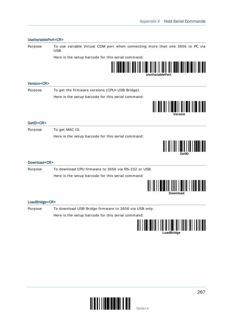
267
Update
Appendix II Host Serial Commands
UseVariablePort<CR>
Purpose To use variable Virtual COM port when connecting more than one 3656 to PC via USB.
Here is the setup barcode for this serial command:
UseVariablePort
Version<CR>
Purpose To get the firmware versions (CPU+USB Bridge).
Here is the setup barcode for this serial command:
Version
GetID<CR>
Purpose To get MAC ID.
Here is the setup barcode for this serial command:
GetID
Download<CR>
Purpose To download CPU firmware to 3656 via RS-232 or USB.
Here is the setup barcode for this serial command:
Download
LoadBridge<CR>
Purpose To download USB Bridge firmware to 3656 via USB only.
Here is the setup barcode for this serial command:
LoadBridge
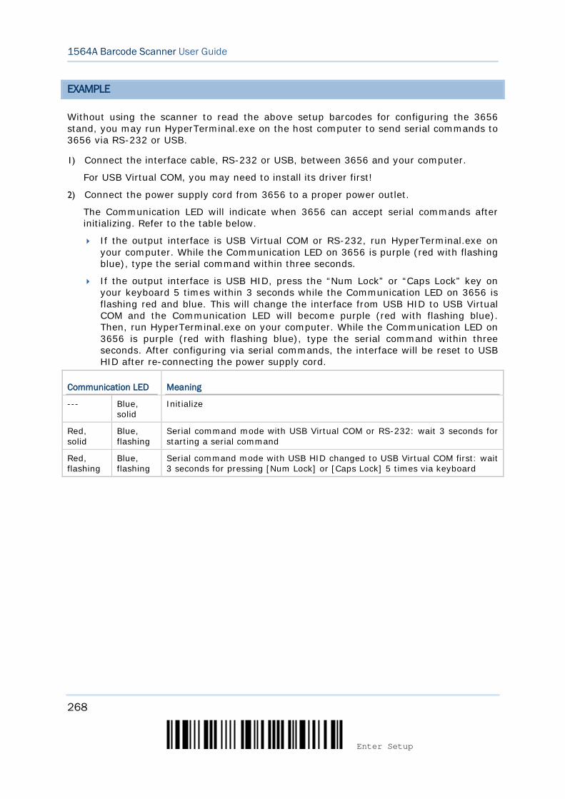
268
Enter Setup
1564A Barcode Scanner User Guide
EXAMPLE
Without using the scanner to read the above setup barcodes for configuring the 3656 stand, you may run HyperTerminal.exe on the host computer to send serial commands to 3656 via RS-232 or USB.
1) Connect the interface cable, RS-232 or USB, between 3656 and your computer.
For USB Virtual COM, you may need to install its driver first!
2) Connect the power supply cord from 3656 to a proper power outlet.
The Communication LED will indicate when 3656 can accept serial commands after initializing. Refer to the table below.
If the output interface is USB Virtual COM or RS-232, run HyperTerminal.exe on your computer. While the Communication LED on 3656 is purple (red with flashing blue), type the serial command within three seconds.
If the output interface is USB HID, press the “Num Lock” or “Caps Lock” key on your keyboard 5 times within 3 seconds while the Communication LED on 3656 is flashing red and blue. This will change the interface from USB HID to USB Virtual COM and the Communication LED will become purple (red with flashing blue). Then, run HyperTerminal.exe on your computer. While the Communication LED on 3656 is purple (red with flashing blue), type the serial command within three seconds. After configuring via serial commands, the interface will be reset to USB HID after re-connecting the power supply cord.
Communication LED Meaning
--- Blue, solid
Initialize
Red, solid
Blue, flashing
Serial command mode with USB Virtual COM or RS-232: wait 3 seconds for starting a serial command
Red, flashing
Blue, flashing
Serial command mode with USB HID changed to USB Virtual COM first: wait 3 seconds for pressing [Num Lock] or [Caps Lock] 5 times via keyboard
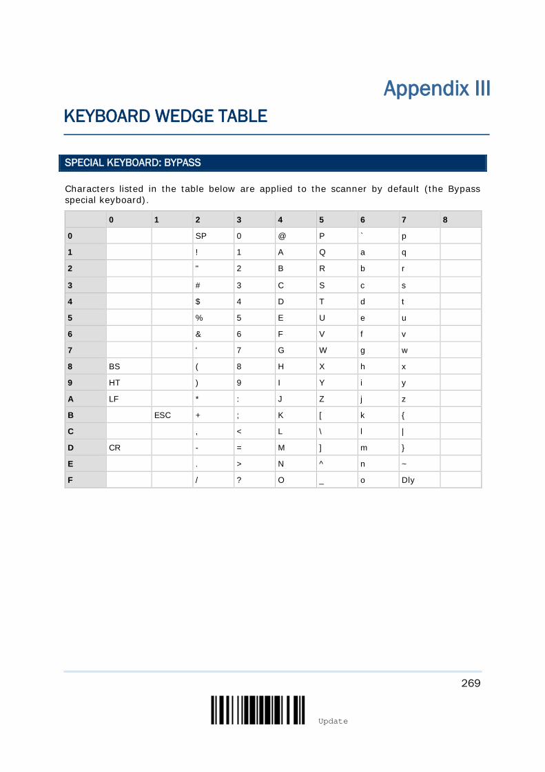
269
Update
SPECIAL KEYBOARD: BYPASS
Characters listed in the table below are applied to the scanner by default (the Bypass special keyboard).
0 1 2 3 4 5 6 7 8
0 SP 0 @ P ` p
1 ! 1 A Q a q
2 " 2 B R b r
3 # 3 C S c s
4 $ 4 D T d t
5 % 5 E U e u
6 & 6 F V f v
7 ' 7 G W g w
8 BS ( 8 H X h x
9 HT ) 9 I Y i y
A LF * : J Z j z
B ESC + ; K [ k {
C , < L \ l |
D CR - = M ] m }
E . > N ^ n ~
F / ? O _ o Dly
Appendix III KEYBOARD WEDGE TABLE

270
Enter Setup
1564A Barcode Scanner User Guide
SPECIAL KEYBOARD: APPLY
When the special keyboard is set to “Apply”, characters listed in the table below are applied to the scanner.
0 1 2 3 4 5 6 7 8
0 F2 SP 0 @ P ` p
1 INS F3 ! 1 A Q a q
2 DLT F4 " 2 B R b r
3 Home F5 # 3 C S c s
4 End F6 $ 4 D T d t
5 Up F7 % 5 E U e u
6 Down F8 & 6 F V f v
7 Left F9 ' 7 G W g w
8 BS F10 ( 8 H X h x
9 HT F11 ) 9 I Y i y
A LF F12 * : J Z j z
B Right ESC + ; K [ k {
C PgUp Exec , < L \ l |
D CR CR* - = M ] m }
E PgDn . > N ^ n ~
F F1 / ? O _ o Dly ENTER*
Note: (1) ~: Digits on the numeric keypad. (2) CR*/ENTER*: ENTER key on the numeric keypad.
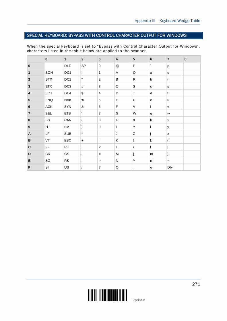
271
Update
Appendix III Keyboard Wedge Table
SPECIAL KEYBOARD: BYPASS WITH CONTROL CHARACTER OUTPUT FOR WINDOWS
When the special keyboard is set to “Bypass with Control Character Output for Windows”, characters listed in the table below are applied to the scanner.
0 1 2 3 4 5 6 7 8
0 DLE SP 0 @ P ` p
1 SOH DC1 ! 1 A Q a q
2 STX DC2 " 2 B R b r
3 ETX DC3 # 3 C S c s
4 EOT DC4 $ 4 D T d t
5 ENQ NAK % 5 E U e u
6 ACK SYN & 6 F V f v
7 BEL ETB ' 7 G W g w
8 BS CAN ( 8 H X h x
9 HT EM ) 9 I Y i y
A LF SUB * : J Z j z
B VT ESC + ; K [ k {
C FF FS , < L \ l |
D CR GS - = M ] m }
E SO RS . > N ^ n ~
F SI US / ? O _ o Dly

272
Enter Setup
1564A Barcode Scanner User Guide
KEY TYPE & STATUS
KEY TYPE
If “BT HID”, “USB HID” or “Keyboard Wedge” is configured for interface, Key Type and Key Status will then become applicable.
*Normal
Scan Code
KEY STATUS
Decide whether or not to change key status when “Normal Key” is selected for Key Type.
Add Shift
Add Left Ctrl
Add Right Ctrl
Add Left Alt
Add Right Alt
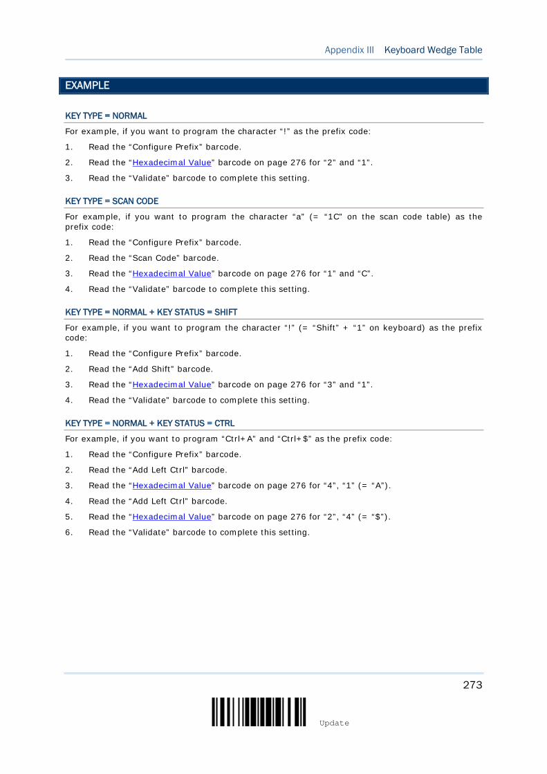
273
Update
Appendix III Keyboard Wedge Table
EXAMPLE
KEY TYPE = NORMAL
For example, if you want to program the character “!” as the prefix code:
1. Read the “Configure Prefix” barcode.
2. Read the “Hexadecimal Value” barcode on page 276 for “2” and “1”.
3. Read the “Validate” barcode to complete this setting.
KEY TYPE = SCAN CODE
For example, if you want to program the character “a” (= “1C” on the scan code table) as the prefix code:
1. Read the “Configure Prefix” barcode.
2. Read the “Scan Code” barcode.
3. Read the “Hexadecimal Value” barcode on page 276 for “1” and “C”.
4. Read the “Validate” barcode to complete this setting.
KEY TYPE = NORMAL + KEY STATUS = SHIFT
For example, if you want to program the character “!” (= “Shift” + “1” on keyboard) as the prefix code:
1. Read the “Configure Prefix” barcode.
2. Read the “Add Shift” barcode.
3. Read the “Hexadecimal Value” barcode on page 276 for “3” and “1”.
4. Read the “Validate” barcode to complete this setting.
KEY TYPE = NORMAL + KEY STATUS = CTRL
For example, if you want to program “Ctrl+A” and “Ctrl+$” as the prefix code:
1. Read the “Configure Prefix” barcode.
2. Read the “Add Left Ctrl” barcode.
3. Read the “Hexadecimal Value” barcode on page 276 for “4”, “1” (= “A”).
4. Read the “Add Left Ctrl” barcode.
5. Read the “Hexadecimal Value” barcode on page 276 for “2”, “4” (= “$”).
6. Read the “Validate” barcode to complete this setting.

274
Enter Setup
1564A Barcode Scanner User Guide
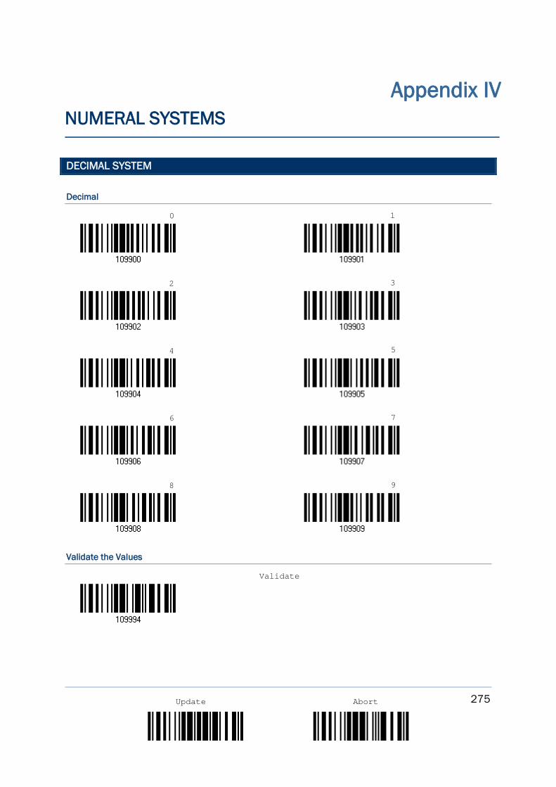
275
Update Abort
DECIMAL SYSTEM
Decimal
Validate the Values
Appendix IV NUMERAL SYSTEMS
0 1
2 3
4 5
6 7
8 9
Validate
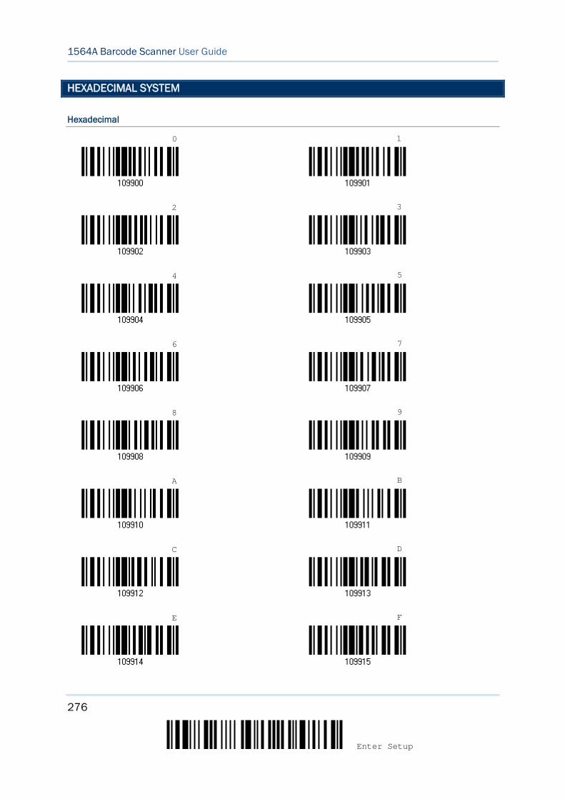
276
Enter Setup
1564A Barcode Scanner User Guide
HEXADECIMAL SYSTEM
Hexadecimal
0 1
2 3
4 5
6 7
8 9
A B
C D
E F
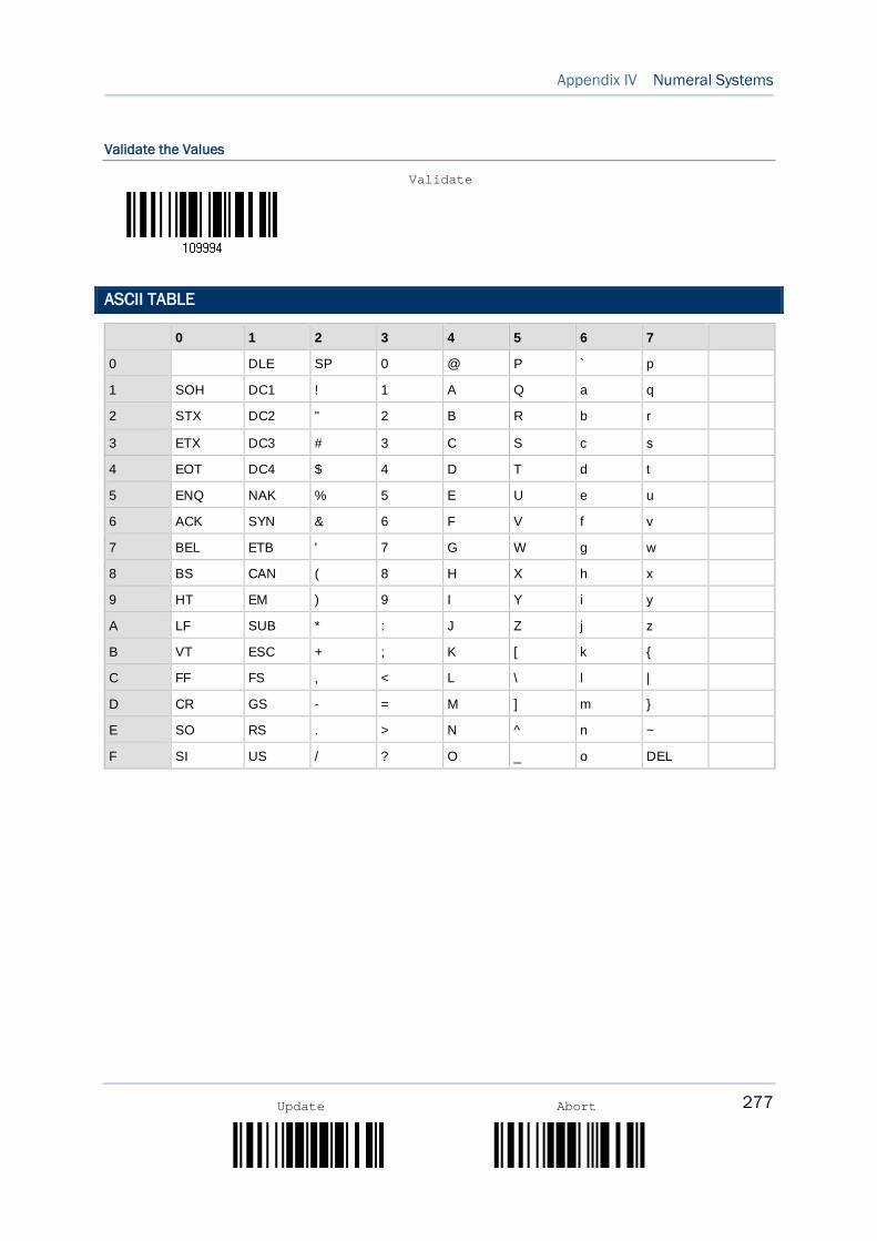
277
Appendix IV Numeral Systems
Update Abort
Validate the Values
ASCII TABLE
0 1 2 3 4 5 6 7
0 DLE SP 0 @ P ` p
1 SOH DC1 ! 1 A Q a q
2 STX DC2 " 2 B R b r
3 ETX DC3 # 3 C S c s
4 EOT DC4 $ 4 D T d t
5 ENQ NAK % 5 E U e u
6 ACK SYN & 6 F V f v
7 BEL ETB ' 7 G W g w
8 BS CAN ( 8 H X h x
9 HT EM ) 9 I Y i y
A LF SUB * : J Z j z
B VT ESC + ; K [ k {
C FF FS , < L \ l |
D CR GS - = M ] m }
E SO RS . > N ^ n ~
F SI US / ? O _ o DEL
Validate
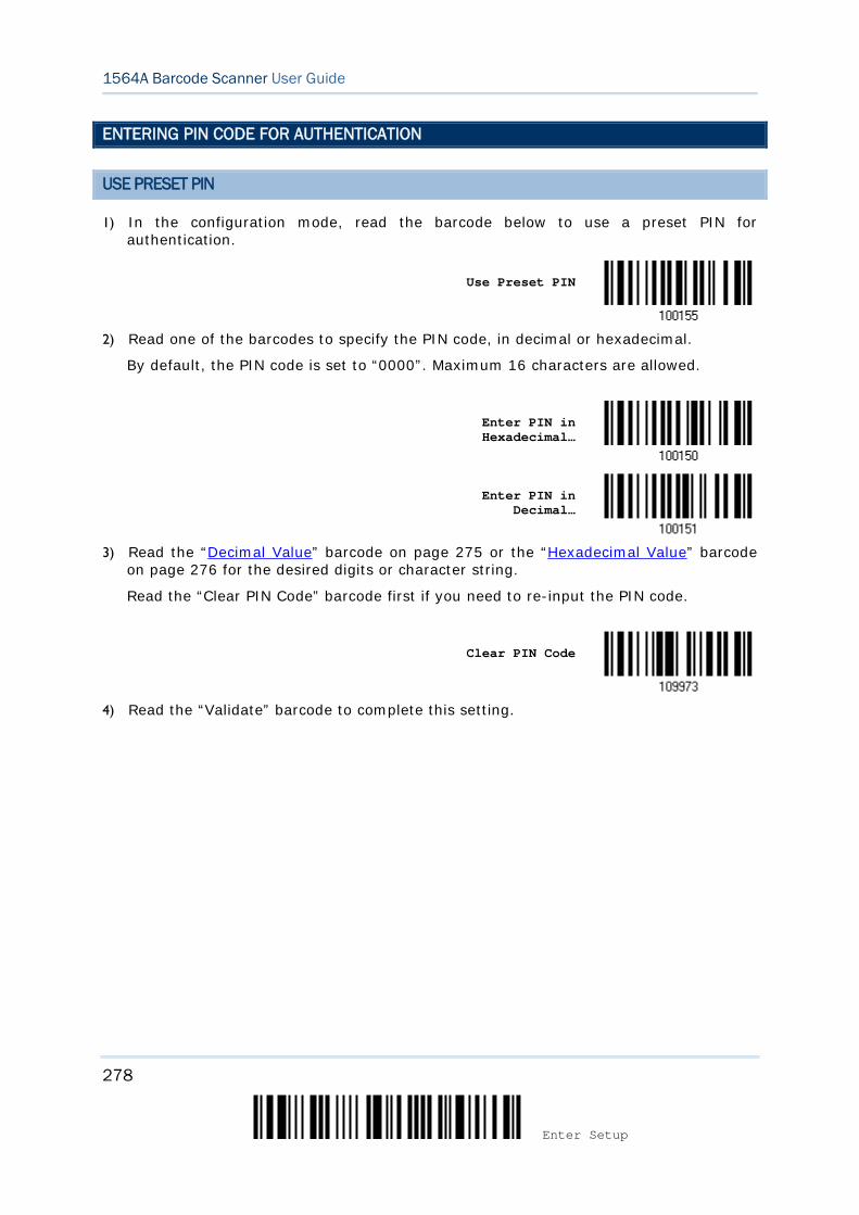
278
Enter Setup
1564A Barcode Scanner User Guide
ENTERING PIN CODE FOR AUTHENTICATION
USE PRESET PIN
1) In the configuration mode, read the barcode below to use a preset PIN for authentication.
Use Preset PIN
2) Read one of the barcodes to specify the PIN code, in decimal or hexadecimal.
By default, the PIN code is set to “0000”. Maximum 16 characters are allowed.
Enter PIN in Hexadecimal…
Enter PIN in Decimal…
3) Read the “Decimal Value” barcode on page 275 or the “Hexadecimal Value” barcode
on page 276 for the desired digits or character string.
Read the “Clear PIN Code” barcode first if you need to re-input the PIN code.
Clear PIN Code
4) Read the “Validate” barcode to complete this setting.
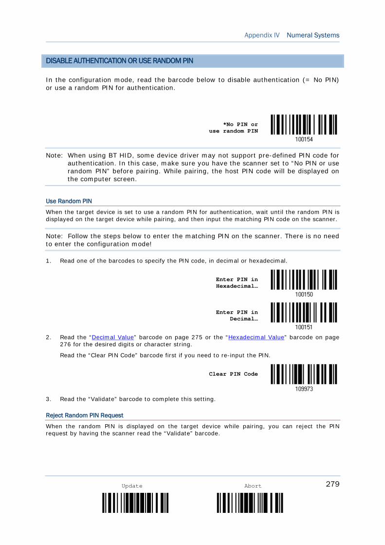
279
Appendix IV Numeral Systems
Update Abort
DISABLE AUTHENTICATION OR USE RANDOM PIN
In the configuration mode, read the barcode below to disable authentication (= No PIN) or use a random PIN for authentication.
*No PIN or use random PIN
Note: When using BT HID, some device driver may not support pre-defined PIN code for authentication. In this case, make sure you have the scanner set to “No PIN or use random PIN” before pairing. While pairing, the host PIN code will be displayed on the computer screen.
Use Random PIN
When the target device is set to use a random PIN for authentication, wait until the random PIN is displayed on the target device while pairing, and then input the matching PIN code on the scanner.
Note: Follow the steps below to enter the matching PIN on the scanner. There is no need to enter the configuration mode!
1. Read one of the barcodes to specify the PIN code, in decimal or hexadecimal.
Enter PIN in Hexadecimal…
Enter PIN in Decimal…
2. Read the “Decimal Value” barcode on page 275 or the “Hexadecimal Value” barcode on page
276 for the desired digits or character string.
Read the “Clear PIN Code” barcode first if you need to re-input the PIN.
Clear PIN Code
3. Read the “Validate” barcode to complete this setting.
Reject Random PIN Request
When the random PIN is displayed on the target device while pairing, you can reject the PIN request by having the scanner read the “Validate” barcode.

280
Enter Setup
1564A Barcode Scanner User Guide

281
Update Abort
The scanner is capable of reading 2D driver’s licenses and other American Association of Motor Vehicle Administrators (AAMVA) compliant ID cards. For compliant 2D licensed card scanning, it decodes the information embedded in the ID cards to a formatted data. This appendix provides the setup barcodes required while ScanMaster utility provides GUI setup that is organized and easy-to-use.
Note: The configured settings are saved in flash memory for access once a driver’s license is read.
LICENSE PARSING SETUP
*License Parse Disable
License Parse Enable
Parse Field Clear
FILE TYPE
You can check the file type of ANSI by scanning the barcode as below.
*Enable
Disable
Appendix V READING DRIVER LICENSES
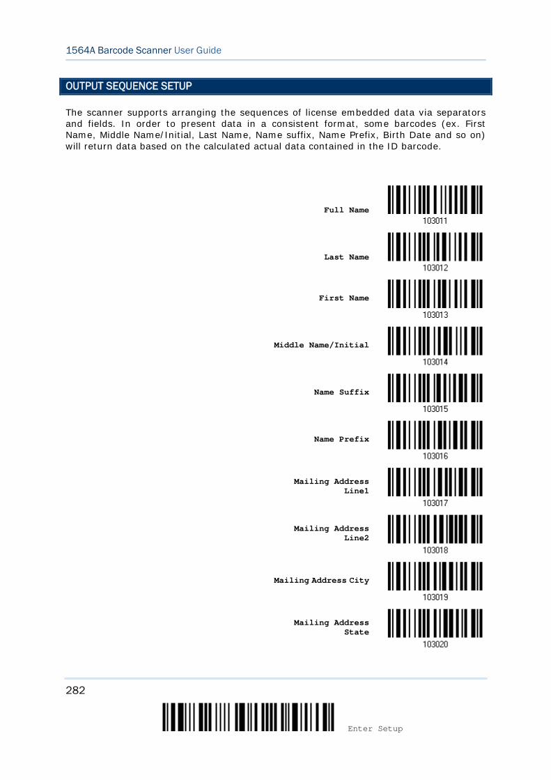
282
Enter Setup
1564A Barcode Scanner User Guide
OUTPUT SEQUENCE SETUP
The scanner supports arranging the sequences of license embedded data via separators and fields. In order to present data in a consistent format, some barcodes (ex. First Name, Middle Name/Initial, Last Name, Name suffix, Name Prefix, Birth Date and so on) will return data based on the calculated actual data contained in the ID barcode.
Full Name
Last Name
First Name
Middle Name/Initial
Name Suffix
Name Prefix
Mailing Address Line1
Mailing Address Line2
Mailing Address City
Mailing Address State
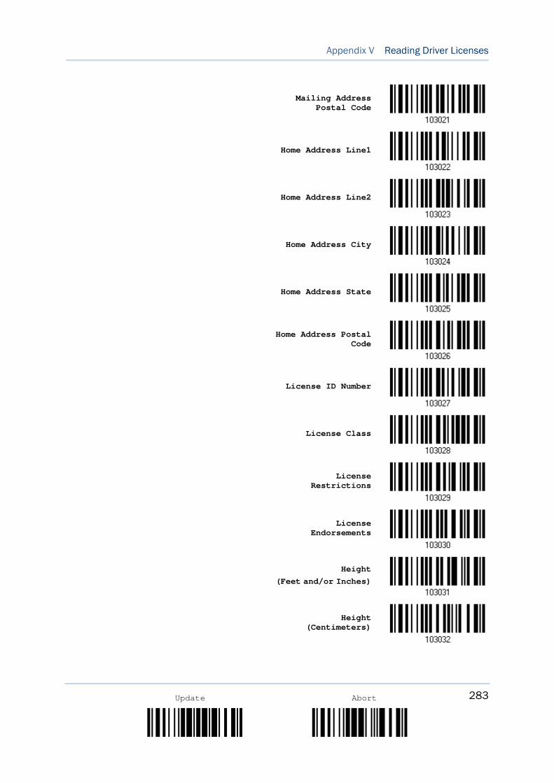
283
Appendix V Reading Driver Licenses
Update Abort
Mailing Address Postal Code
Home Address Line1
Home Address Line2
Home Address City
Home Address State
Home Address Postal Code
License ID Number
License Class
License Restrictions
License Endorsements
Height (Feet and/or Inches)
Height (Centimeters)
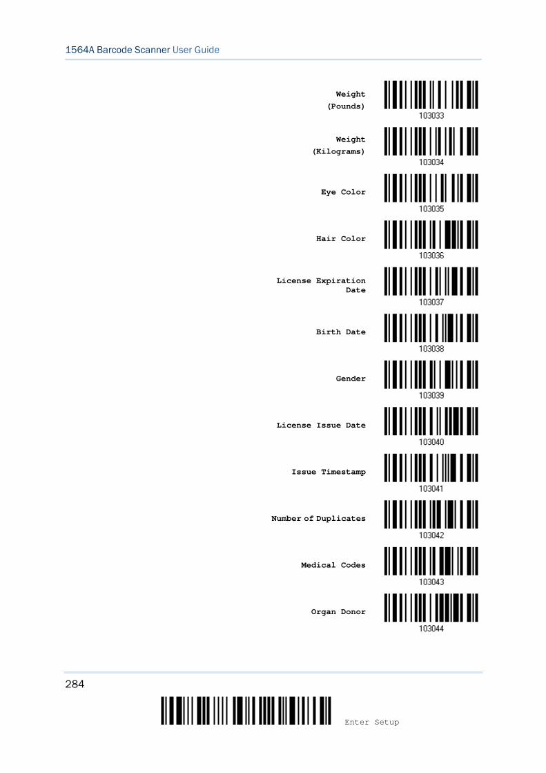
284
Enter Setup
1564A Barcode Scanner User Guide
Weight (Pounds)
Weight (Kilograms)
Eye Color
Hair Color
License Expiration Date
Birth Date
Gender
License Issue Date
Issue Timestamp
Number of Duplicates
Medical Codes
Organ Donor
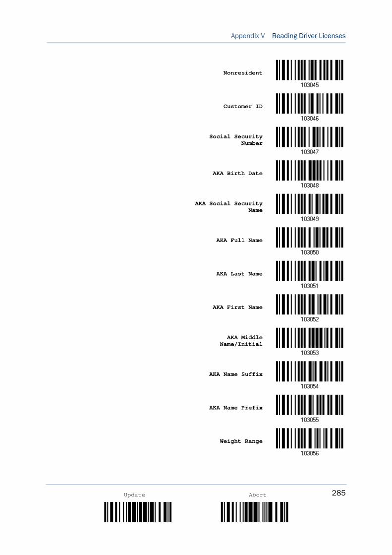
285
Appendix V Reading Driver Licenses
Update Abort
Nonresident
Customer ID
Social Security Number
AKA Birth Date
AKA Social Security Name
AKA Full Name
AKA Last Name
AKA First Name
AKA Middle Name/Initial
AKA Name Suffix
AKA Name Prefix
Weight Range
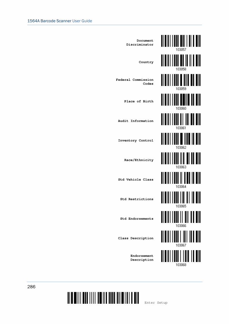
286
Enter Setup
1564A Barcode Scanner User Guide
Document Discriminator
Country
Federal Commission Codes
Place of Birth
Audit Information
Inventory Control
Race/Ethnicity
Std Vehicle Class
Std Restrictions
Std Endorsements
Class Description
Endorsement Description
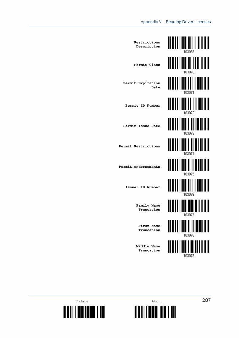
287
Appendix V Reading Driver Licenses
Update Abort
Restrictions Description
Permit Class
Permit Expiration Date
Permit ID Number
Permit Issue Date
Permit Restrictions
Permit endorsements
Issuer ID Number
Family Name Truncation
First Name Truncation
Middle Name Truncation
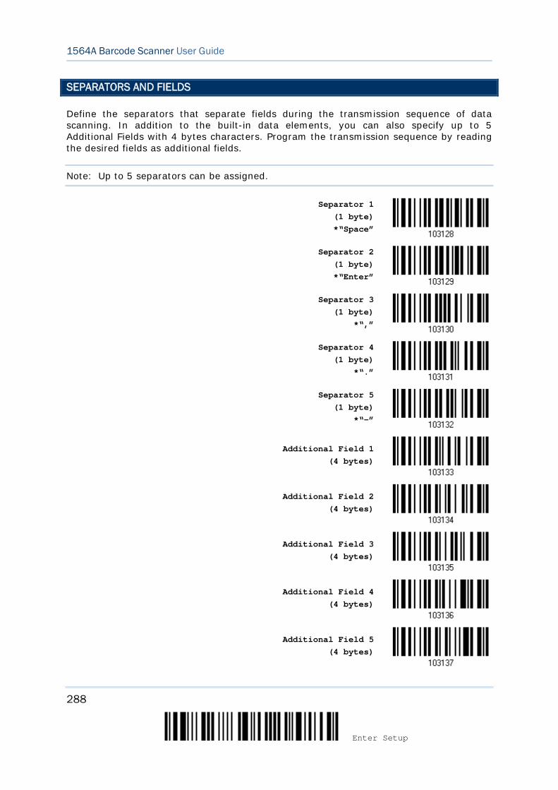
288
Enter Setup
1564A Barcode Scanner User Guide
SEPARATORS AND FIELDS
Define the separators that separate fields during the transmission sequence of data scanning. In addition to the built-in data elements, you can also specify up to 5 Additional Fields with 4 bytes characters. Program the transmission sequence by reading the desired fields as additional fields.
Note: Up to 5 separators can be assigned.
Separator 1
(1 byte) *“Space”
Separator 2 (1 byte) *“Enter”
Separator 3 (1 byte)
*“,”
Separator 4
(1 byte) *“.”
Separator 5 (1 byte)
*“-”
Additional Field 1
(4 bytes)
Additional Field 2 (4 bytes)
Additional Field 3 (4 bytes)
Additional Field 4 (4 bytes)
Additional Field 5 (4 bytes)
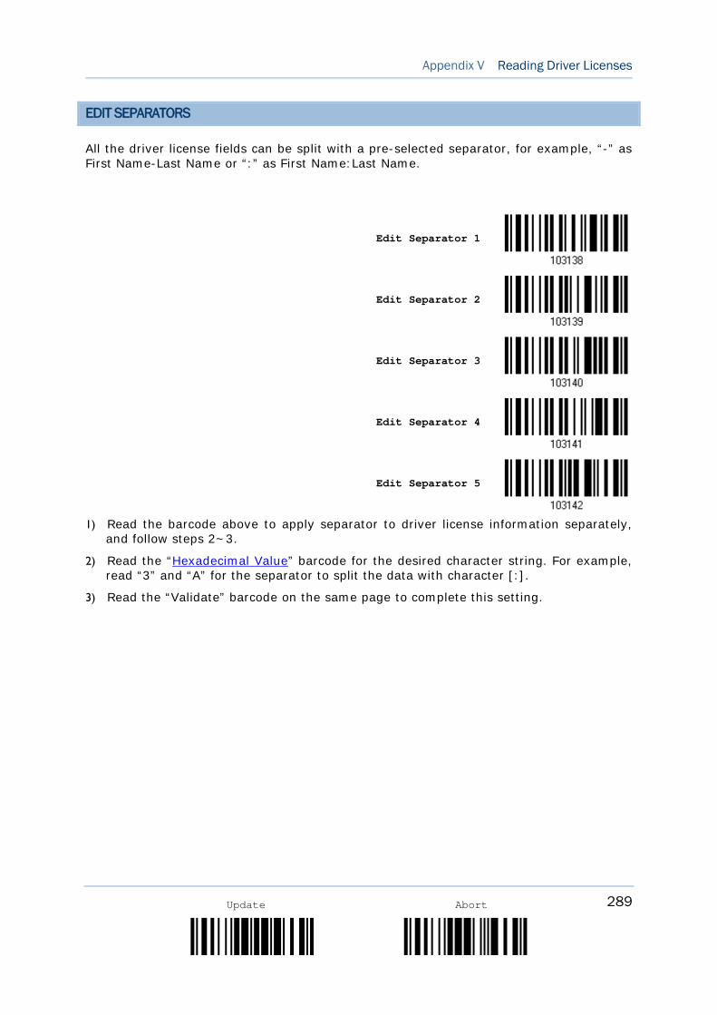
289
Appendix V Reading Driver Licenses
Update Abort
EDIT SEPARATORS
All the driver license fields can be split with a pre-selected separator, for example, “-” as First Name-Last Name or “:” as First Name:Last Name.
Edit Separator 1
Edit Separator 2
Edit Separator 3
Edit Separator 4
Edit Separator 5
1) Read the barcode above to apply separator to driver license information separately,
and follow steps 2~3.
2) Read the “Hexadecimal Value” barcode for the desired character string. For example, read “3” and “A” for the separator to split the data with character [:].
3) Read the “Validate” barcode on the same page to complete this setting.
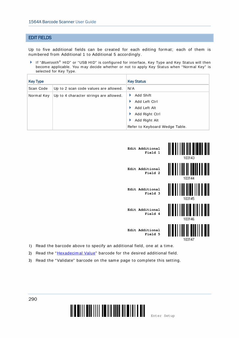
290
Enter Setup
1564A Barcode Scanner User Guide
EDIT FIELDS
Up to five additional fields can be created for each editing format; each of them is numbered from Additional 1 to Additional 5 accordingly.
If “Bluetooth® HID” or “USB HID” is configured for interface, Key Type and Key Status will then become applicable. You may decide whether or not to apply Key Status when “Normal Key” is selected for Key Type.
Key Type Key Status
Scan Code Up to 2 scan code values are allowed. N/A
Normal Key Up to 4 character strings are allowed. Add Shift
Add Left Ctrl
Add Left Alt
Add Right Ctrl
Add Right Alt
Refer to Keyboard Wedge Table.
Edit Additional Field 1
Edit Additional Field 2
Edit Additional Field 3
Edit Additional Field 4
Edit Additional Field 5
1) Read the barcode above to specify an additional field, one at a time.
2) Read the “Hexadecimal Value” barcode for the desired additional field.
3) Read the “Validate” barcode on the same page to complete this setting.
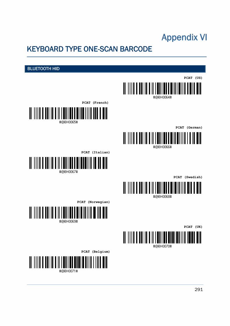
291
Update Abort
BLUETOOTH HID
PCAT (US)
PCAT (French)
PCAT (German)
PCAT (Italian)
PCAT (Swedish)
PCAT (Norwegian)
PCAT (UK)
PCAT (Belgium)
Appendix VI KEYBOARD TYPE ONE-SCAN BARCODE
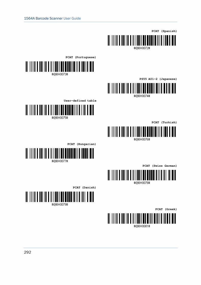
292
Enter Setup
1564A Barcode Scanner User Guide
PCAT (Spanish)
PCAT (Portuguese)
PS55 A01-2 (Japanese)
User-defined table
PCAT (Turkish)
PCAT (Hungarian)
PCAT (Swiss German)
PCAT (Danish)
PCAT (Greek)
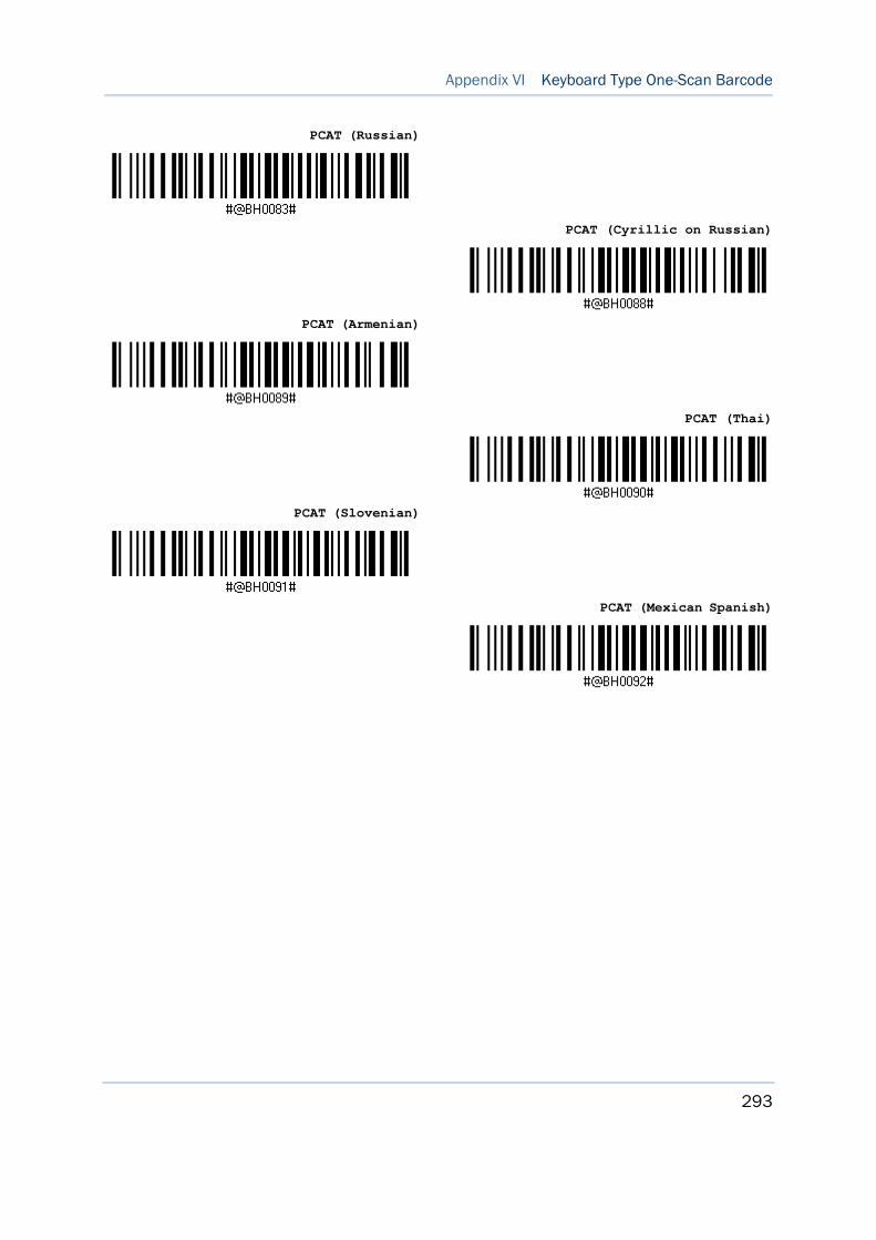
293
Appendix VI Keyboard Type One-Scan Barcode
Update Abort
PCAT (Russian)
PCAT (Cyrillic on Russian)
PCAT (Armenian)
PCAT (Thai)
PCAT (Slovenian)
PCAT (Mexican Spanish)
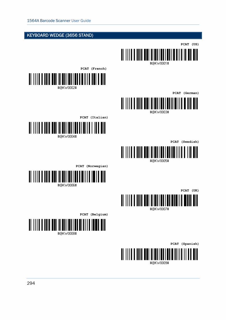
294
Enter Setup
1564A Barcode Scanner User Guide
KEYBOARD WEDGE (3656 STAND)
PCAT (US)
PCAT (French)
PCAT (German)
PCAT (Italian)
PCAT (Swedish)
PCAT (Norwegian)
PCAT (UK)
PCAT (Belgium)
PCAT (Spanish)
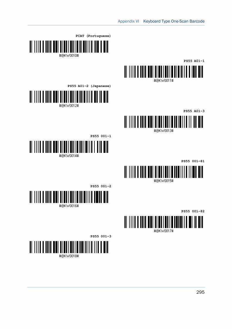
295
Appendix VI Keyboard Type One-Scan Barcode
Update Abort
PCAT (Portuguese)
PS55 A01-1
PS55 A01-2 (Japanese)
PS55 A01-3
PS55 001-1
PS55 001-81
PS55 001-2
PS55 001-82
PS55 001-3

296
Enter Setup
1564A Barcode Scanner User Guide
PS55 001-8A
PS55 002-1, 003-1
PS55 002-81, 003-81
PS55 002-2, 003-2
PS55 002-82, 003-82
PS55 002-3, 003-3
PS55 002-8A, 003-8A
IBM 3477 Type 4 (Japanese)
PS2-30
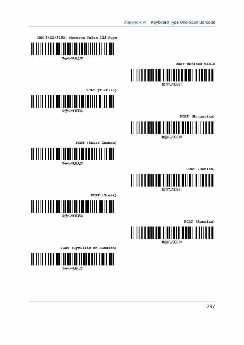
297
Appendix VI Keyboard Type One-Scan Barcode
Update Abort
IBM 34XX/319X, Memorex Telex 122 Keys
User-defined table
PCAT (Turkish)
PCAT (Hungarian)
PCAT (Swiss German)
PCAT (Danish)
PCAT (Greek)
PCAT (Russian)
PCAT (Cyrillic on Russian)
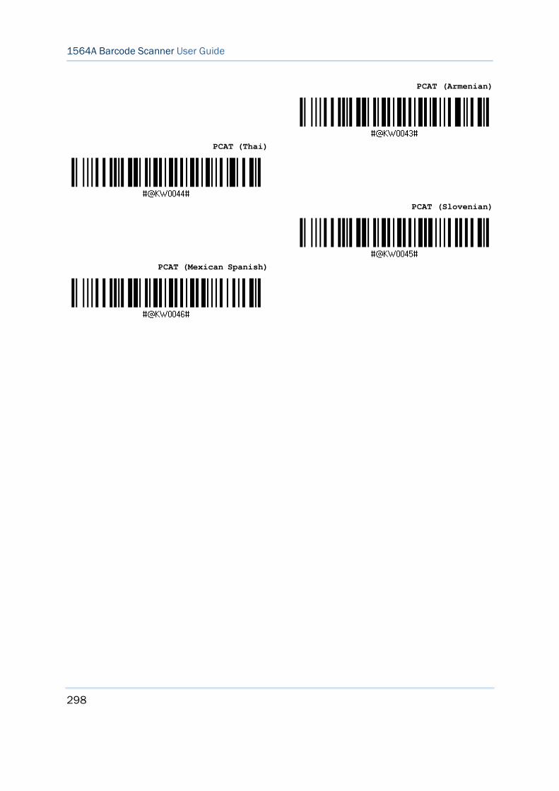
298
Enter Setup
1564A Barcode Scanner User Guide
PCAT (Armenian)
PCAT (Thai)
PCAT (Slovenian)
PCAT (Mexican Spanish)
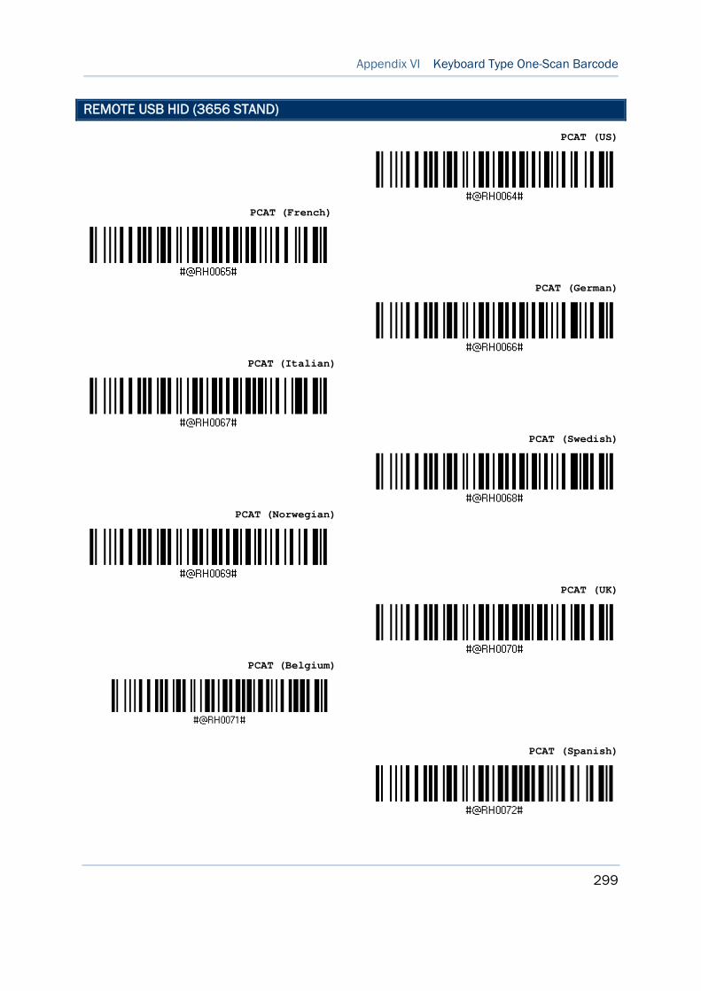
299
Appendix VI Keyboard Type One-Scan Barcode
Update Abort
REMOTE USB HID (3656 STAND)
PCAT (US)
PCAT (French)
PCAT (German)
PCAT (Italian)
PCAT (Swedish)
PCAT (Norwegian)
PCAT (UK)
PCAT (Belgium)
PCAT (Spanish)
300
Enter Setup
1564A Barcode Scanner User Guide
PCAT (Portuguese)
PS55 A01-2 (Japanese)
User-defined table
PCAT (Turkish)
PCAT (Hungarian)
PCAT (Swiss German)
PCAT (Danish)
PCAT (Greek)
PCAT (Russian)

301
Appendix VI Keyboard Type One-Scan Barcode
Update Abort
PCAT (Cyrillic on Russian)
PCAT (Armenian)
PCAT (Thai)
PCAT (Slovenian)
PCAT (Mexican Spanish)