1538 IEEE SENSORS JOURNAL, VOL. 15, NO. 3, MARCH...
7
1538 IEEE SENSORS JOURNAL, VOL. 15, NO. 3, MARCH 2015 Fine-Grained Indoor Localization Using Single Access Point With Multiple Antennas Fuxi Wen, Member, IEEE, and Chen Liang Abstract— We propose a single access point-based fine-grained indoor localization system in multipath environments using 802.11ac Wi-Fi signals. The physical layer of 802.11ac supports orthogonal frequency-division multiplexing modulation (OFDM) scheme, more antennas, and multiuser multiple-input multiple-output. Angle-of-arrival (AOA) of the paths can be obtained using the phase difference among all the antennas. Similarly, time of arrival (TOA) information is estimated from the phase difference among all the subcarriers of the OFDM signal. After obtaining the AOA and TOA information of the dominant paths, an auto paring approach is proposed to identify the line-of-sight (LOS) path. Mobile device can be localized using the estimated AOA and TOA information of the LOS path. Performance analysis of the proposed method is provided. Numerical simulations are carried out to evaluate the performance. Based on the simulation results, meter or submeter level accuracy is obtained for the proposed method. Index Terms—Indoor localization, fine-grained, multiple-input multiple-output, angle of arrival, time of arrival, orthogonal frequency-division multiplexing, channel frequency response, access point, mobile device, line-of-sight. I. I NTRODUCTION I NDOOR localization is one of essential technologies for location-based applications. Compared with outdoor posi- tioning, indoor localization is more challenging, since GPS signals are rarely accessible, yet room-level or even sub-meter precision is often required [1]. Due to the ubiquitous deploy- ment of wireless networks and devices, extensive wireless indoor localization techniques have been proposed for the past few decades [2]. Recently, two new opportunities have arisen in the design of 802.11ac Wi-Fi based fine-grained indoor localization systems: 1) More Antennas and Increased Bandwidth: Future gener- ations of 802.11ac chips will support wider channels, more antennas, more spatial streams and multi-user MIMO. For the upcoming 802.11ac standard, channel bandwidth increased from the maximum of 40 MHz in 802.11n, and now up to 80 or even 160 MHz. Furthermore, 802.11ac defines up to eight spatial streams and Wi-Fi access points (APs) are incorporated up to 8 antennas. Manuscript received September 28, 2014; revised October 10, 2014; accepted October 17, 2014. Date of publication October 22, 2014; date of current version December 18, 2014. The associate editor coordinating the review of this paper and approving it for publication was Dr. Stefan J. Rupitsch. F. Wen is with the School of Electrical and Electronic Engineering, Nanyang Technological University, Singapore 639798 (e-mail: [email protected]). C. Liang is with the School of Computer Science and Technology, Xi’an University of Posts and Telecommunications, Xi’an 710121, China (e-mail: [email protected]). Color versions of one or more of the figures in this paper are available online at http://ieeexplore.ieee.org. Digital Object Identifier 10.1109/JSEN.2014.2364121 2) Channel State Information (CSI) for OFDM System: In current widely used OFDM systems, where data are modu- lated on multiple subcarriers in different frequencies and trans- mitted simultaneously, CSI is a fine-grained complex value (amplitude and phase) from the PHY layer which describes the channel response on each subcarrier in the frequency domain [3], [4]. With the upcoming 802.11ac standard and channel response information for the OFDM system, some indoor localization pioneer works have demonstrated submeter or even centimeter- level accuracy. An AOA based indoor localization system called Array-Track is developed in [5], which achieves median 25 cm location accuracy when clients are stationary indoors. To obtain the AOA information, APs with multiple antennas are needed. Minimum two APs are required to localize the mobile nodes. In [6], the authors propose a novel approach called FILA, which explores the frequency diversity of the sub- carriers in OFDM systems. A refined indoor radio propagation model is proposed to represent the relationship between CSI and distance. The FILA system is implemented on commercial 802.11 network interface controllers (NICs) to evaluate its performance in different indoor scenarios. The experimental results show that the accuracy and speed of distance calculation can be significantly enhanced using CSI. Similar to the Array-Track system, minimum two APs are required for FILA. In [7], the authors design and implement a fine-grained indoor fingerprinting system (FIFS). FIFS explores a PHY layer CSI that specifies the channel status over all the subcarriers for location fingerprinting in wireless local area network. FIFS is a nature extension of FILA, which benefits from the multipath effects. Instead of using two APs, a single anchor based indoor localization system using smart antenna is proposed in [8] and [9]. Though directional antennas are capable of obtaining both angle and distance estimates, the angle accuracy is low, it is still far from handy access. In this paper, we propose a fine-grained indoor localization algorithm using single access point with multiple antennas (FILSAM). For the upcoming 802.11ac standard, TOA can be estimated in frequency domain using the multiple sub-carrier of the OFDM signal. AOA is obtained by using the spatial information between the multiple antennas. Our motivation is to exploit the possibility of localizing the mobile node using single AP for 802.11 ac Wi-Fi signal. Both TOA and AOA of the LOS path information are required to localize the mobile node. For the proposed method, the following assumptions have been made, the LOS path is exist between 1530-437X © 2014 IEEE. Personal use is permitted, but republication/redistribution requires IEEE permission. See http://www.ieee.org/publications_standards/publications/rights/index.html for more information.
-
Upload
trankhuong -
Category
Documents
-
view
213 -
download
0
Transcript of 1538 IEEE SENSORS JOURNAL, VOL. 15, NO. 3, MARCH...

1538 IEEE SENSORS JOURNAL, VOL. 15, NO. 3, MARCH 2015
Fine-Grained Indoor Localization Using SingleAccess Point With Multiple Antennas
Fuxi Wen, Member, IEEE, and Chen Liang
Abstract— We propose a single access point-based fine-grainedindoor localization system in multipath environments using802.11ac Wi-Fi signals. The physical layer of 802.11ac supportsorthogonal frequency-division multiplexing modulation (OFDM)scheme, more antennas, and multiuser multiple-inputmultiple-output. Angle-of-arrival (AOA) of the paths canbe obtained using the phase difference among all the antennas.Similarly, time of arrival (TOA) information is estimated fromthe phase difference among all the subcarriers of the OFDMsignal. After obtaining the AOA and TOA information ofthe dominant paths, an auto paring approach is proposed toidentify the line-of-sight (LOS) path. Mobile device can belocalized using the estimated AOA and TOA information ofthe LOS path. Performance analysis of the proposed methodis provided. Numerical simulations are carried out to evaluatethe performance. Based on the simulation results, meter orsubmeter level accuracy is obtained for the proposed method.
Index Terms— Indoor localization, fine-grained, multiple-inputmultiple-output, angle of arrival, time of arrival, orthogonalfrequency-division multiplexing, channel frequency response,access point, mobile device, line-of-sight.
I. INTRODUCTION
INDOOR localization is one of essential technologies forlocation-based applications. Compared with outdoor posi-
tioning, indoor localization is more challenging, since GPSsignals are rarely accessible, yet room-level or even sub-meterprecision is often required [1]. Due to the ubiquitous deploy-ment of wireless networks and devices, extensive wirelessindoor localization techniques have been proposed for the pastfew decades [2].
Recently, two new opportunities have arisen in the design of802.11ac Wi-Fi based fine-grained indoor localization systems:
1) More Antennas and Increased Bandwidth: Future gener-ations of 802.11ac chips will support wider channels, moreantennas, more spatial streams and multi-user MIMO. Forthe upcoming 802.11ac standard, channel bandwidth increasedfrom the maximum of 40 MHz in 802.11n, and now upto 80 or even 160 MHz. Furthermore, 802.11ac defines upto eight spatial streams and Wi-Fi access points (APs) areincorporated up to 8 antennas.
Manuscript received September 28, 2014; revised October 10, 2014;accepted October 17, 2014. Date of publication October 22, 2014; date ofcurrent version December 18, 2014. The associate editor coordinating thereview of this paper and approving it for publication was Dr. Stefan J.Rupitsch.
F. Wen is with the School of Electrical and Electronic Engineering, NanyangTechnological University, Singapore 639798 (e-mail: [email protected]).
C. Liang is with the School of Computer Science and Technology, Xi’anUniversity of Posts and Telecommunications, Xi’an 710121, China (e-mail:[email protected]).
Color versions of one or more of the figures in this paper are availableonline at http://ieeexplore.ieee.org.
Digital Object Identifier 10.1109/JSEN.2014.2364121
2) Channel State Information (CSI) for OFDM System:In current widely used OFDM systems, where data are modu-lated on multiple subcarriers in different frequencies and trans-mitted simultaneously, CSI is a fine-grained complex value(amplitude and phase) from the PHY layer which describesthe channel response on each subcarrier in the frequencydomain [3], [4].
With the upcoming 802.11ac standard and channel responseinformation for the OFDM system, some indoor localizationpioneer works have demonstrated submeter or even centimeter-level accuracy.
An AOA based indoor localization system calledArray-Track is developed in [5], which achieves median25 cm location accuracy when clients are stationary indoors.To obtain the AOA information, APs with multiple antennasare needed. Minimum two APs are required to localize themobile nodes. In [6], the authors propose a novel approachcalled FILA, which explores the frequency diversity of the sub-carriers in OFDM systems. A refined indoor radio propagationmodel is proposed to represent the relationship betweenCSI and distance. The FILA system is implemented oncommercial 802.11 network interface controllers (NICs)to evaluate its performance in different indoor scenarios.The experimental results show that the accuracy and speedof distance calculation can be significantly enhanced usingCSI. Similar to the Array-Track system, minimum twoAPs are required for FILA. In [7], the authors design andimplement a fine-grained indoor fingerprinting system (FIFS).FIFS explores a PHY layer CSI that specifies the channelstatus over all the subcarriers for location fingerprinting inwireless local area network. FIFS is a nature extension ofFILA, which benefits from the multipath effects. Instead ofusing two APs, a single anchor based indoor localizationsystem using smart antenna is proposed in [8] and [9].Though directional antennas are capable of obtaining bothangle and distance estimates, the angle accuracy is low, it isstill far from handy access.
In this paper, we propose a fine-grained indoor localizationalgorithm using single access point with multiple antennas(FILSAM). For the upcoming 802.11ac standard, TOA can beestimated in frequency domain using the multiple sub-carrierof the OFDM signal. AOA is obtained by using the spatialinformation between the multiple antennas. Our motivationis to exploit the possibility of localizing the mobile nodeusing single AP for 802.11 ac Wi-Fi signal. Both TOA andAOA of the LOS path information are required to localizethe mobile node. For the proposed method, the followingassumptions have been made, the LOS path is exist between
1530-437X © 2014 IEEE. Personal use is permitted, but republication/redistribution requires IEEE permission.See http://www.ieee.org/publications_standards/publications/rights/index.html for more information.

WEN AND LIANG: FINE-GRAINED INDOOR LOCALIZATION USING SINGLE AP WITH MULTIPLE ANTENNAS 1539
MD and AP, the clocks of MD and AP are synchronized andthe multiple antennas are calibrated. The main contributionsare as follows: different from Array-Track and FILA, theproposed method is a single AP based, which use boththe AOA and TOA information of the LOS path to localize themobile devices. A LOS path identification technique is pro-pose, assuming that the LOS path is the shortest. Performanceanalysis and numerical studies are also provided to evaluate theperformance of the proposed method. Based on the simulationresults, meter or submeter level accuracy is obtained for theproposed method.
The rest of this paper is organized as follows. Systemmodel is introduced in Section II. In Section III, we presentsthe proposed single AP based indoor localization system.This is followed by the algorithm analysis of the proposedmethod which is provided in Section IV. Numerical resultsare presented in Section V. Finally, conclusions are presentedin Section VI.
II. SYSTEM MODEL
We consider an AP with M identical antenna elements,the antenna elements are arranged along a line in spacewith uniform spacing, and the inter-element spacing is halfwavelength with respect to the center frequency fc. Withoutloss of generality, we assume that the center of the AP isselected as the origin of the two-dimensional Cartesian coor-dinate system and the uniform linear array arranged along the xaxis. The mobile device (MD) using single antenna to transmitOFDM signals.
Within the bandwidth (BW), the N sub-carrier frequencies{ f1, . . . , fN } are equally spaced by � f . The K multipathcomponents are indexed and the propagation delays τk arein ascending order. As a result τ1 in the model denotesthe propagation delay of the line-of-sight (LOS) path and{τ2, . . . , τK } are non-line-of-sight (NLOS) propagation paths.
The frequency domain channel response is given by
H =⎡⎢⎣
h1,1 · · · h1,N...
. . ....
hM,1 · · · hM,N
⎤⎥⎦ ∈ CM×N (1)
where hm,n is the channel response measured at the mthantenna of AP for frequency fn , and
hm,n =K∑
k=1
αk · e− j2π fnτk · e jπ(m−1) fnfc
cos(θk) + wm,n (2)
where αk is the complex attenuation for the kth path, τk and θk
are the propagation delay and angle of arrival of the kth path,respectively. Measurement noise wm,n is assumed to bezero-mean additive white Gaussian with variance σ 2.We assume that L sets of channel response are measured tolocalize the mobile device.
III. PROPOSED METHOD
The proposed method consists the following steps: AOAestimation, TOA estimation, LOS path identification andlocalization.
A. AOA Estimation
Theoretically, AOA information can be obtained by usingthe phase difference among the different antennas. There aretwo important challengers to make the phase array signalprocessing practical using the off-the-shelf hardwares [10].
1) Calibration: Each antenna incorporates a local oscillatorto convert the incoming radio frequency signal to base band.The frequency of all the oscillators can be locked to avoiddrifting over time by sharing the same NIC, however, theseoscillators still have an unknown phase offset relative to oneanother.
2) Synchronization: For the cutting-edge AP with multipleNICs, synchronization across NICs are needed. Aftersynchronization, calibration is carried out among all the anten-nas to correct the phase offset.
Some pioneer works on AP synchronization and calibrationhave been done in [11]. In the following, we assume thatthe multiple antennas of AP are synchronized and calibrated.Although a linear array can determine AOAs, it cannot deter-mine which side of the array the signal is arriving from.Other array geometries such as circular array, rectangulararray can be used to remove this ambiguity. In this paper,we assume that the AOAs of all the paths are between0° and 180°.
Minimum one column of channel response H is requiredto estimate AOA. The channel response corresponding to thecarrier frequency is used for the proposed method, which isdenoted as hc ∈ CM×1. In [10], multiple signal classification(MUSIC) algorithm [12] is used to obtain the AOA of theincoming signals. Since the multipath signals are highlycorrelated, decorrelation techniques such as spatialsmoothing [13] are needed for MUSIC algorithm. Instead ofusing MUSIC algorithm, in this paper method of directionestimation (MODE) method [14] is used to estimate AOA.Comparing with MUSIC algorithm, MODE can handle highlycorrelated or coherent sources. It also achieves asymptoticefficiency for both uncorrelated and coherent source scenarios.
The MODE algorithm is based on eigenvalue decomposi-tion of the autocorrelation matrix of the measured channelresponse hc,
R = E{hchHc } = U�VH , (3)
where E{·} denotes expectation operator, � = diag{λ1,λ2, . . . , λM } is the square diagonal matrix containing singularvalues with λ1 ≥ λ2 ≥ · · · ≥ λM ≥ 0, while U ∈ CM×M andV ∈ CM×M are orthonormal matrices whose columns are thecorresponding left and right singular vectors of R, respectively.Expression (11) can be rewritten as the following form:
R = U[s]�[s](V[s])H + U[n]�[n](V[n])H (4)
where the columns of matrices U[s] ∈ CM×K and U[n]contain the signal and noise subspace eigenvectors, respec-tively. Diagonal matrices �[s] = diag {λ1, . . . , λK } and �[n] =diag {λK+1, . . . , λM } contain the K and M − K signal andnoise subspace eigenvalues, respectively.
The complex vector b = [b0, b1, . . . , bK ]T ∈ C(K+1)×1
is defined to parameterize the signal components via the
1540 IEEE SENSORS JOURNAL, VOL. 15, NO. 3, MARCH 2015
following polynomial
b0 + b1z + · · · + bK zK = b0
K∏k=1
(1 − e jωk
)(5)
where
ωk = π cos(θk). (6)
Since the polynomial has all its zeros on the unit circle,the coefficients of b should satisfy the conjugate symme-try constraint. The frequencies of the r th dimension canbe estimated indirectly via minimizing the following costfunction [14]:
J (b) = tr{P(b)U[s]W
(U[s])H }
(7)
where P(b) = B(BH B
)−1BH , and B is a standard Toeplitz
matrix
BH =
⎡⎢⎢⎣
b0 · · · bK 0
. . .. . .
0 b0 · · · bK
⎤⎥⎥⎦, (8)
W = (�[s] − δ2I
)2{�[s]}−1 and δ2 is the estimated noise
power, which is given by δ2 = 1M−K tr
{�[n]}.
Minimization of (7) is obtained by the following two-stepprocedure, which is non-iterative [14].
Step 1: Obtain an initial estimate b of b by minimizing
J1(b) = tr{
BH U[s]W[U[s]]H
B}. (9)
Step 2: Obtain the refined estimate b of b by minimizing
J2(b) = tr{(
BH B)−1BH U[s]W
[U[s]]H
B}. (10)
To exclude the trivial solution, the norm constraint ‖b‖2 = 1is imposed on b.
The AOAs can be estimated by rooting the polynomial withcoefficients b, which is denoted as θ = {θ1, θ2, . . . , θK }
B. TOA Estimation
To obtain the TOAs, the minimum requirement is oneset of measurement from one antenna, which is denoted ashr ∈ C1×N . In [15], a frequency domain super-resolutiontechnique using MUSIC algorithm is proposed for TOAestimation. Similar to AOA estimation, MODE algorithm isapplied to estimate TOA. We first calculate the autocorrelationmatrix of hr .
R = E{hHr hr } = U�VH , (11)
where � = diag {λ1, λ2, . . . , λN } is the square diagonal matrixcontaining singular values with λ1 ≥ λ2 ≥ · · · ≥ λN ≥ 0,while U ∈ CN×N and V ∈ CN×N are orthonormal matriceswhose columns are the corresponding left and right singularvectors of R, respectively. Expression (11) can be rewritten asthe following form:
R = U[s]�[s](V[s])H + U[n]�[n](V[n])H (12)
where the columns of matrices U[s] ∈ CM×K and U[n] con-tain the signal and noise subspace eigenvectors, respectively.Diagonal matrices �[s] = diag {λ1, . . . , λK } and �[n] =diag {λK+1, . . . , λN } contain the K and N − K signal andnoise subspace eigenvalues, respectively.
Following the same steps as in the previous sectionAOA estimation using the new U[s], �[s] and �[n]. We canestimate the TOAs of the paths. For TOA estimation, therelationship between ωk and τk is given by
ωk = −2π� f τk . (13)
The estimated TOAs are denoted as τ = {τ1, τ2, . . . , τK }.
C. LOS Path Identification and Localization
Joint TOA and AOA parameter estimation can be consideredas a two dimensional spectrum estimation problem. Usingthe existing spectrum analysis techniques, the parameter pairs(τlos, θlos) and (τnlos, θnlos) can be obtained either by findingthe three peaks in the spectrum or the roots of a correspondingpolynomial function. To reduce the computational complexity,in this paper, TOA and AOA are estimated separately. Onceτlos is available, the corresponding LOS path θlos estimationreduces to a one dimensional spectrum estimation problem.Parameters τlos and θlos are automatic paired.
Assuming that the LOS path is the shortest, thenτlos = τ1 Let h = vec{H} ∈ CM N×1, where vec{·} denotesa vectorization of a matrix.
G(θ) =⎡⎢⎣
g1,1 · · · g1,N...
. . ....
gM,1 · · · gM,N
⎤⎥⎦ ∈ CM×N (14)
where gm,n is given by
gm,n = e− j2π fnτlos · e jπ(m−1)fnfc
cos(θ) (15)
Let g(θ) = vec {G(θ)} ∈ CM N×1, the AOA for the LOS pathis obtained by solving the following optimization problem,
θlos = arg maxθ1,...,θK
|gH (θk)h|2. (16)
The estimated AOA and TOA information of the LOSpath θlos and τlos can be used to localize the mobile node.With θlos and τlos, localize the mobile node is straightfor-ward. The localization of the mobile device is given by[x, y] = [rlos cos(θlos), rlos sin(θlos)], where rlos = c × τlosand c = 3 × 10⁸ m/s is the propagation speed.
The proposed FILSAM indoor localization algorithm issummarized in Algorithm 1.
IV. ALGORITHM ANALYSIS
A. Computational Complexity
Notice that the computational complexity of singular valuedecomposition (SVD) is discussed in [16]. While that ofMODE is studied with details in [17]. By extending the resultsof [16] and [17], we are able to determine the computationalload of FILSAM, which is provided in Table I.

WEN AND LIANG: FINE-GRAINED INDOOR LOCALIZATION USING SINGLE AP WITH MULTIPLE ANTENNAS 1541
Algorithm 1 Indoor Localization Using Single AP1: Obtain the channel response H which is defined in (1).2: Extract hc from H.3: Estimate AOAs θ = {θ1, θ2, . . . , θK } using MODE.4: Extract hr from H.5: Estimate TOAs τ = {τ1, τ2, . . . , τK } using MODE.6: Assuming the LOS path is shortest, τlos = τ1.7: Obtain AOA (θlos) of the LOS path by solving (16).8: Localize the mobile device using θlos and τlos.
TABLE I
COMPUTATIONAL COMPLEXITY OF FILSAM ALGORITHM
In summary, the computational complexity of the proposedalgorithm is
O(κ(M + N)K L + M N K
+ 1
2K (M + N − 2K )(20K 2 + 33K + 17)
), (17)
where κ is a constant that depends on the design of the SVDalgorithm [16].
B. Mean Square Error
Before analyzing the mean square error (MSE) of theFILSAM, we first define the manifold A, which is
A = [a1 a2 · · · aK
] ∈ CP×K (18)
where ak = [e jωk e j2ωk · · · e j Pωk ]T . The correspondingderivative matrix D of A is defined as
D = [d1 d2 · · · dK
] ∈ CP×K (19)
where dk � ∂ak∂ωk
is the partial derivative of ak with respectto ωk .
The mean and variance of the conventional matrix-basedMODE algorithm have been derived in [14] by makinguse of the perturbation analysis. Following [14], the covari-ance matrix of the r th dimension frequency estimatesω = [ω1, ω2, . . . , ωK ]T is computed as
C = σ 2
2L
[Re
(H � ST
)]−1
·{
Re(
H �(
EH E)−T )}
·[Re
(H � ST
)]−1(20)
where
H = DH(
I − A(
AH A)−1
AH)
D, (21)
Fig. 1. Simulation setup, distance is not up to scale.
and
S = E{α(l)αH (l)}, (22)
where α(l) = [α1(l), α2(l), . . . , αK (l)]T is the complex ampli-tude vector of the K paths.
The MSE of ωk is then
MSE(ωk) = [C]k,k (23)
where [ C ]k,k denotes the (k, k) entry of C.For AOA estimation, let parameter P = M and using the
relationship in (6), we obtain the MSE analysis for AOA.Similarly, for TOA esitmaition, let let parameter P = N andusing the relationship in (13), we obtain the MSE analysisfor TOA.
V. SIMULATION AND EXPERIMENT RESULTS
A. Simulation Results
Computer simulations have been carried out to evaluatethe performance of the proposed approach. Matlab is usedto obtain the simulation results. The centre of the uniformlinear array (ULA) is chosen as the origin (0, 0) of Cartesiancoordinate system. The elements of the ULA are placed alongthe x-axis. The mobile node is placed at (−0.872, 9.962),the two reflectors are placed at (5.156, 5.156) and(−10.752, 15.355). Free-space path loss model is consideredto model the propagation channel.
The simulation setup is shown in Fig. 1 and the detailsis as follows. An AP equiped with uniform linear array(4 and 8 antennas) are considered, the inter-element spacing ishalf wavelength with respect to carrier frequency fc = 5 GHz.Within the bandwidth (BW = 20 MHz, 40 MHz, 80 MHz), thesub-carrier frequencies are centered at carrier frequency andarranged uniformly and the frequency interval is � f = 2 MHz.The mobile device (MD) uses single antenna to transmit allthe sub-carrier frequencies. Three multipaths are consideredin the following simulations, whose parameters are given

1542 IEEE SENSORS JOURNAL, VOL. 15, NO. 3, MARCH 2015
TABLE II
PARAMETERS USED TO SIMULATE THE MULTIPATHS
Fig. 2. Average localization error (ALE) versus SNR for different numberof antennas (4 and 8) and bandwidths (20 MHz, 40 MHz and 80 MHz).The distance between AP and MD is 10 m. All the results are obtained over500 independent simulation runs.
in Table II. Average localization error (ALE) is used toevaluate the performance of the proposed method, which isdefined as
ALE = 1
J
J∑j=1
√(x j − x)2 + (y j − y)2 (24)
where [x, y] are the location of the mobile device and J is thenumber of indepent runs. The following results are obtainedover 500 independent simulation runs.
The ALE performance versus signal-to-noise ratio (SNR) isshown in Fig. 2. We observe that for AP with 8 antennas, theALE is less than 1 m, when the SNR is larger than 5 dB. Sucha accuracy is obtained, using only 20 MHz bandwidth. Whenthe SNR is larger than 10 dB, 0.5 m accuracy is obtained onlyusing 4 antennas and 20 MHz bandwidth. The CumulativeDistribution Function (CDF) of localization error is shownin Fig. 3. LOS path detection probability with respect to SNRis provided in Fig. 4.
B. NLOS Path Is Close to the LOS Path
To evaluate the performance of the proposed method whenthe NLOS path is close to the LOS path, the followingtwo simulations are carried out. In the first simulation, theAOA for the NLOS path is close to the LOS path, withangle difference �θ . In the second simulation, the TOA forthe NLOS path is close to the LOS path, with distancedifference �d .
The AOA estimation performance for NLOS signals areclose to the LOS signal (�θ = 5°, 10°, 15°) is shownin Fig. 5. The TOA estimation performance for NLOS signals
Fig. 3. Cumulative Distribution Function (CDF) of localization error,SNR = 10 dB.
Fig. 4. LOS path detection probability with respect to SNR, BW = 80 MHz.
Fig. 5. The AOA estimation performance for NLOS signals are close to theLOS signal.
are close to the LOS signal (�d = 1m, 2m, 5m) is shownin Fig. 6.
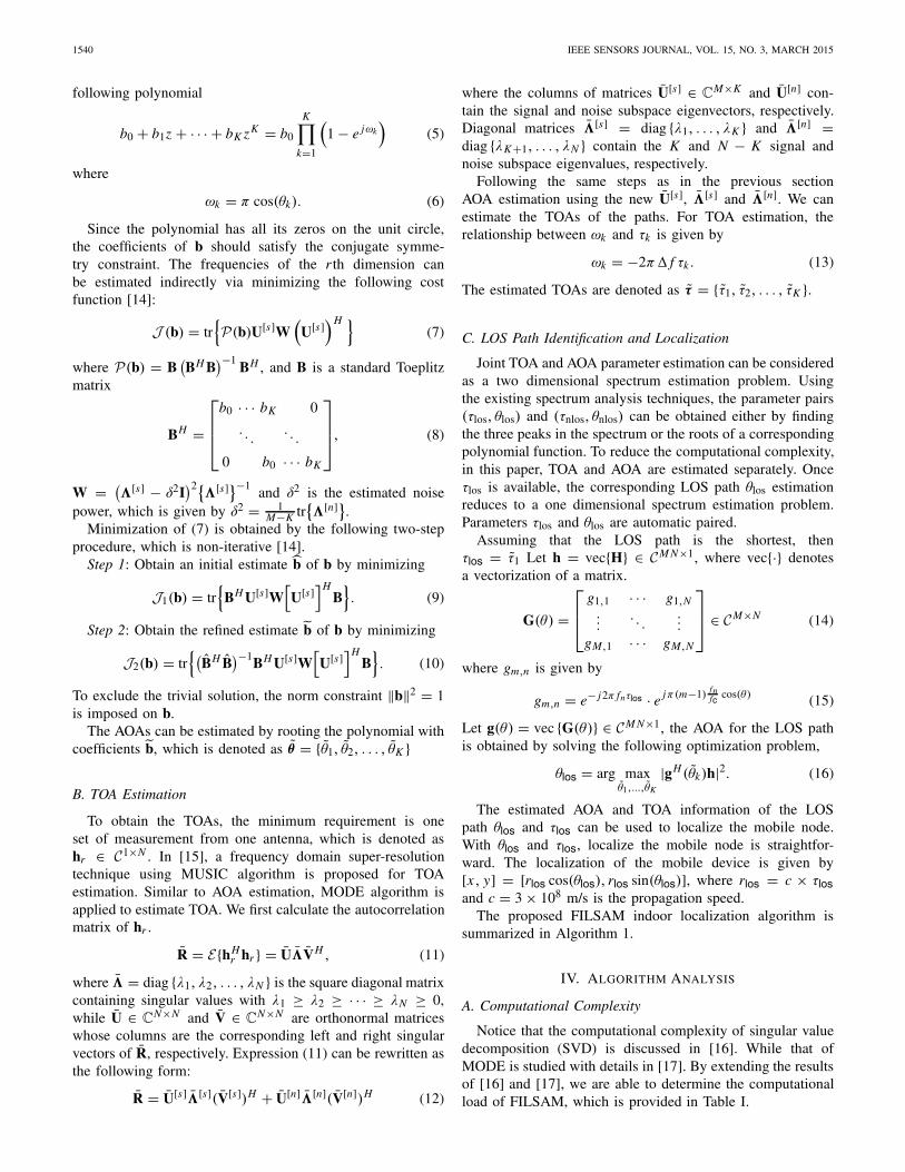
For a ULA, the performance of MODE is better thanthat of the MUSIC algorithm. The comparison results forMODE and MUSIC with spatial smoothing is providedin Fig. 7.
WEN AND LIANG: FINE-GRAINED INDOOR LOCALIZATION USING SINGLE AP WITH MULTIPLE ANTENNAS 1543
Fig. 6. The TOA estimation performance for NLOS signals are close to theLOS signal.
Fig. 7. The comparison results for MODE and MUSIC with spatialsmoothing.
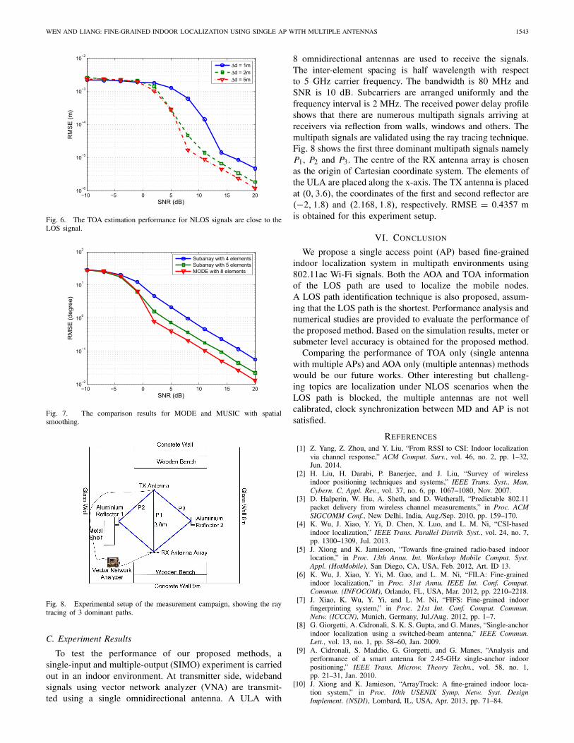
Fig. 8. Experimental setup of the measurement campaign, showing the raytracing of 3 dominant paths.
C. Experiment Results
To test the performance of our proposed methods, asingle-input and multiple-output (SIMO) experiment is carriedout in an indoor environment. At transmitter side, widebandsignals using vector network analyzer (VNA) are transmit-ted using a single omnidirectional antenna. A ULA with
8 omnidirectional antennas are used to receive the signals.The inter-element spacing is half wavelength with respectto 5 GHz carrier frequency. The bandwidth is 80 MHz andSNR is 10 dB. Subcarriers are arranged uniformly and thefrequency interval is 2 MHz. The received power delay profileshows that there are numerous multipath signals arriving atreceivers via reflection from walls, windows and others. Themultipath signals are validated using the ray tracing technique.Fig. 8 shows the first three dominant multipath signals namelyP1, P2 and P3. The centre of the RX antenna array is chosenas the origin of Cartesian coordinate system. The elements ofthe ULA are placed along the x-axis. The TX antenna is placedat (0, 3.6), the coordinates of the first and second reflector are(−2, 1.8) and (2.168, 1.8), respectively. RMSE = 0.4357 mis obtained for this experiment setup.
VI. CONCLUSION
We propose a single access point (AP) based fine-grainedindoor localization system in multipath environments using802.11ac Wi-Fi signals. Both the AOA and TOA informationof the LOS path are used to localize the mobile nodes.A LOS path identification technique is also proposed, assum-ing that the LOS path is the shortest. Performance analysis andnumerical studies are provided to evaluate the performance ofthe proposed method. Based on the simulation results, meter orsubmeter level accuracy is obtained for the proposed method.
Comparing the performance of TOA only (single antennawith multiple APs) and AOA only (multiple antennas) methodswould be our future works. Other interesting but challeng-ing topics are localization under NLOS scenarios when theLOS path is blocked, the multiple antennas are not wellcalibrated, clock synchronization between MD and AP is notsatisfied.
REFERENCES
[1] Z. Yang, Z. Zhou, and Y. Liu, “From RSSI to CSI: Indoor localizationvia channel response,” ACM Comput. Surv., vol. 46, no. 2, pp. 1–32,Jun. 2014.
[2] H. Liu, H. Darabi, P. Banerjee, and J. Liu, “Survey of wirelessindoor positioning techniques and systems,” IEEE Trans. Syst., Man,Cybern. C, Appl. Rev., vol. 37, no. 6, pp. 1067–1080, Nov. 2007.
[3] D. Halperin, W. Hu, A. Sheth, and D. Wetherall, “Predictable 802.11packet delivery from wireless channel measurements,” in Proc. ACMSIGCOMM Conf., New Delhi, India, Aug./Sep. 2010, pp. 159–170.
[4] K. Wu, J. Xiao, Y. Yi, D. Chen, X. Luo, and L. M. Ni, “CSI-basedindoor localization,” IEEE Trans. Parallel Distrib. Syst., vol. 24, no. 7,pp. 1300–1309, Jul. 2013.
[5] J. Xiong and K. Jamieson, “Towards fine-grained radio-based indoorlocation,” in Proc. 13th Annu. Int. Workshop Mobile Comput. Syst.Appl. (HotMobile), San Diego, CA, USA, Feb. 2012, Art. ID 13.
[6] K. Wu, J. Xiao, Y. Yi, M. Gao, and L. M. Ni, “FILA: Fine-grainedindoor localization,” in Proc. 31st Annu. IEEE Int. Conf. Comput.Commun. (INFOCOM), Orlando, FL, USA, Mar. 2012, pp. 2210–2218.
[7] J. Xiao, K. Wu, Y. Yi, and L. M. Ni, “FIFS: Fine-grained indoorfingerprinting system,” in Proc. 21st Int. Conf. Comput. Commun.Netw. (ICCCN), Munich, Germany, Jul./Aug. 2012, pp. 1–7.
[8] G. Giorgetti, A. Cidronali, S. K. S. Gupta, and G. Manes, “Single-anchorindoor localization using a switched-beam antenna,” IEEE Commun.Lett., vol. 13, no. 1, pp. 58–60, Jan. 2009.
[9] A. Cidronali, S. Maddio, G. Giorgetti, and G. Manes, “Analysis andperformance of a smart antenna for 2.45-GHz single-anchor indoorpositioning,” IEEE Trans. Microw. Theory Techn., vol. 58, no. 1,pp. 21–31, Jan. 2010.
[10] J. Xiong and K. Jamieson, “ArrayTrack: A fine-grained indoor loca-tion system,” in Proc. 10th USENIX Symp. Netw. Syst. DesignImplement. (NSDI), Lombard, IL, USA, Apr. 2013, pp. 71–84.

1544 IEEE SENSORS JOURNAL, VOL. 15, NO. 3, MARCH 2015
[11] J. Xiong and K. Jamieson, “SecureAngle: Improving wireless securityusing angle-of-arrival signatures,” in Proc. 9th ACM Workshop HotTopics Netw. (HotNets), Monterey, CA, USA, Oct. 2010, Art. ID 11.
[12] R. O. Schmidt, “Multiple emitter location and signal parameter esti-mation,” IEEE Trans. Antennas Propag., vol. 34, no. 3, pp. 276–280,Mar. 1986.
[13] T.-J. Shan, M. Wax, and T. Kailath, “On spatial smoothing for direction-of-arrival estimation of coherent signals,” IEEE Trans. Acoust., Speech,Signal Process., vol. 33, no. 4, pp. 806–811, Aug. 1985.
[14] P. Stoica and K. Sharman, “Maximum likelihood methods for direction-of-arrival estimation,” IEEE Trans. Acoust., Speech, Signal Process.,vol. 38, no. 7, pp. 1132–1143, Jul. 1990.
[15] X. Li and K. Pahlavan, “Super-resolution TOA estimation with diversityfor indoor geolocation,” IEEE Trans. Wireless Commun., vol. 3, no. 1,pp. 224–234, Jan. 2004.
[16] M. Haardt, F. Roemer, and G. Del Galdo, “Higher-order SVD-basedsubspace estimation to improve the parameter estimation accuracy inmultidimensional harmonic retrieval problems,” IEEE Trans. SignalProcess., vol. 56, no. 7, pp. 3198–3213, Jul. 2008.
[17] J. Li, P. Stoica, and Z.-S. Liu, “Comparative study of IQML and MODEdirection-of-arrival estimators,” IEEE Trans. Signal Process., vol. 46,no. 1, pp. 149–160, Jan. 1998.
Fuxi Wen received the B.Eng. degree in electronicengineering from the Harbin University of Scienceand Technology, Harbin, China, in 2004, the M.Eng.degree in electronic engineering from Xidian Univer-sity, Xi’an, China, in 2007, and the Ph.D. degree inelectrical and electronic engineering from NanyangTechnological University, Singapore, in 2013.
He was a Research and Development Engineerwith the Panasonic Research and DevelopmentCenter Singapore, Singapore, in 2011. From 2011 to2013, he was a Research Associate with the School
of Electrical and Electronic Engineering, Nanyang Technological University,where he was a Research Fellow from 2013 to 2014.
Dr. Wen’s research interests include statistical signal processing, array signalprocessing, and distributed parameter estimation.
Chen Liang is currently an Assistant Professor with the School of ComputerScience and Technology, Xi’an University of Posts and Telecommunications,Xi’an, China.