150MM ELECTRIC EARTH BORER - … Earth Auger... · 150MM ELECTRIC EARTH BORER MODEL NO: CEA150 PART...
12
OPERATING & MAINTENANCE INSTRUCTIONS GC0915 150MM ELECTRIC EARTH BORER MODEL NO: CEA150 PART NO: 3400997
-
Upload
vuongduong -
Category
Documents
-
view
217 -
download
0
Transcript of 150MM ELECTRIC EARTH BORER - … Earth Auger... · 150MM ELECTRIC EARTH BORER MODEL NO: CEA150 PART...

150MM ELECTRIC EARTH BORERMODEL NO: CEA150
PART NO: 3400997
OPERATING & MAINTENANCEINSTRUCTIONS
GC0915
P
INTRODUCTION
Thank you for purchasing this CLARKE Electric Earth Borer designed for boring holes in soil only, for fence posts, re-forestation, and similar operations.
Before attempting to use this product, please read this manual thoroughly and follow the instructions carefully. In doing so you will ensure the safety of yourself and that of others around you, and you can look forward to your purchase giving you long and satisfactory service.
GUARANTEE
This product is guaranteed against faulty manufacture for a period of 12 months from the date of purchase. Please keep your receipt which will be required as proof of purchase.
This guarantee is invalid if the product is found to have been abused or tampered with in any way, or not used for the purpose for which it was intended.
Faulty goods should be returned to their place of purchase, no product can be returned to us without prior permission.
This guarantee does not effect your statutory rights.
ENVIRONMENTAL RECYCLING POLICY
Through purchase of this product, the customer is taking on the obligation to deal with the WEEE in accordance with the WEEE regulations in relation to the treatment, recycling & recovery and environmentally sound disposal of the WEEE.
In effect, this means that this product must not be disposed of with general household waste. It must be disposed of according to the laws governing Waste Electrical and Electronic Equipment (WEEE) at a recognised disposal facility.
If disposing of this product or any damaged components, do not dispose of with general waste. This product contains valuable raw materials. Metal products should be taken to your local civic amenity site for recycling of metal products.
2arts & Service: 020 8988 7400 / E-mail: [email protected] or [email protected]
P
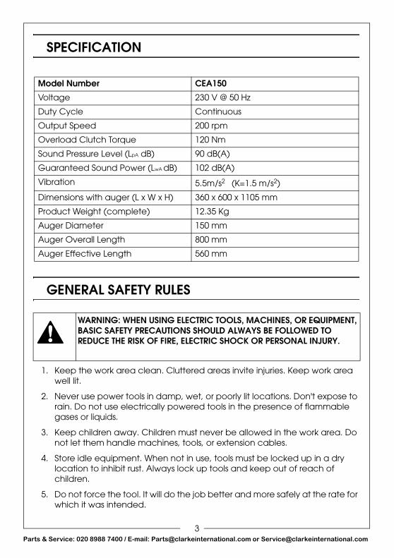
SPECIFICATION
GENERAL SAFETY RULES
1. Keep the work area clean. Cluttered areas invite injuries. Keep work area well lit.
2. Never use power tools in damp, wet, or poorly lit locations. Don't expose to rain. Do not use electrically powered tools in the presence of flammable gases or liquids.
3. Keep children away. Children must never be allowed in the work area. Do not let them handle machines, tools, or extension cables.
4. Store idle equipment. When not in use, tools must be locked up in a dry location to inhibit rust. Always lock up tools and keep out of reach of children.
5. Do not force the tool. It will do the job better and more safely at the rate for which it was intended.
Model Number CEA150
Voltage 230 V @ 50 Hz
Duty Cycle Continuous
Output Speed 200 rpm
Overload Clutch Torque 120 Nm
Sound Pressure Level (LpA dB) 90 dB(A)
Guaranteed Sound Power (LwA dB) 102 dB(A)
Vibration 5.5m/s2 (K=1.5 m/s2)
Dimensions with auger (L x W x H) 360 x 600 x 1105 mm
Product Weight (complete) 12.35 Kg
Auger Diameter 150 mm
Auger Overall Length 800 mm
Auger Effective Length 560 mm
WARNING: WHEN USING ELECTRIC TOOLS, MACHINES, OR EQUIPMENT, BASIC SAFETY PRECAUTIONS SHOULD ALWAYS BE FOLLOWED TO REDUCE THE RISK OF FIRE, ELECTRIC SHOCK OR PERSONAL INJURY.
3arts & Service: 020 8988 7400 / E-mail: [email protected] or [email protected]
P
6. Dress properly. Do not wear loose clothing or jewellery which could be caught in moving parts.
7. Use eye and hand protection and footwear for this type of appliance. Always wear approved impact safety goggles.
8. Do not abuse the power cable. Do not yank it to disconnect it from the socket. Do not carry power tools by the cable.
9. Disconnect the power. Unplug when not in use, before servicing, and when changing accessories.
10. Avoid unintentional starting. Be sure the switch is in the OFF position when not in use and before plugging in.
11. Stay alert. Watch what you are doing, use common sense. Do not operate any tool when you are tired.
12. Check for damaged parts. Before using any tool, any part that appears damaged should be carefully checked to determine that it will operate properly and perform its intended function. Do not use the tool if the switch does not turn on and off properly.
13. Guard against electric shock. Prevent body contact with grounded surfaces.
14. Replacement parts and accessories. When servicing, your Clarke dealer will only use only identical replacement parts. Use of any other parts will void the warranty. Only use accessories intended for use with this tool.
15. Do not operate tool if under the influence of alcohol or drugs. If there is any doubt, do not operate the tool.
16. Never use this machine for boring in landfill or soil known to contain large rocks or unknown debris.
17. Always be alert and adopt a firm stance when handling the machine. Be prepared for the machine to jar suddenly, should the auger come into contact with a submerged or heavy object, heavy clay, or tree roots etc.
18. Always check to ensure the auger securing pin is secure before each use.
19. Always use both hands to control the machine.
20. Always check, before use, to ensure there are no submerged drains, pipes, culverts etc, that may interfere with the boring operation.
21. Always keep bystanders well clear of the boring operation.
4arts & Service: 020 8988 7400 / E-mail: [email protected] or [email protected]

P
ELECTRICAL CONNECTIONS
Before switching the product on, make sure that the voltage of your electricity supply is the same as that indicated on the rating plate. This product is designed to operate on 230VAC 50Hz. Connecting it to any other power source may cause damage.
This product may be fitted with a non-rewireable plug. If it is necessary to change the fuse in the plug, the fuse cover must be refitted. If the fuse cover becomes lost or damaged, the plug must not be used until a suitable replacement is obtained.
If the plug has to be changed because it is not suitable for your socket, or due to damage, it should be cut off and a replacement fitted, following the wiring instructions shown below. The old plug must be disposed of safely, as insertion into a mains socket could cause an electrical hazard.
If the colours of the wires in the power cable of this product do not correspond with the markings on the terminals of your plug, proceed as follows.
• The wire which is coloured Blue must be connected to the terminal which is marked N or coloured Black.
• The wire which is coloured Brown must be connected to the terminal which is marked L or coloured Red.
We strongly recommend that this machine is connected to the mains supply via a Residual Current Device (RCD) If in any doubt, consult a qualified electrician. DO NOT attempt any repairs yourself. This is a class II product which does not require an earth connection.
WARNING! Read these electrical safety instructions thoroughly before connecting the product to the mains supply.
WARNING! The wires in the power cable of this product are coloured in accordance with the following code:Blue = Neutral Brown = Live
Plug must be BS1363/A approved.
Always fit a 13 Amp fuse.
Ensure that the outer sheath of the cable is firmly held by the clamp
Neutral(Blue)
Live(Brown)
5arts & Service: 020 8988 7400 / E-mail: [email protected] or [email protected]

P
PRODUCT OVERVIEW
NO DESCRIPTION NO DESCRIPTION
1 Left Handle 4 Power Cable
2 Right Handle 5 Power Plug
3 Trigger Switch with Lock 6 Auger Bit
1
3
2
6
5
4
6arts & Service: 020 8988 7400 / E-mail: [email protected] or [email protected]

P
INSTALLING THE AUGER BIT
1. Slide the auger bit onto the drive shaft, insert the securing pin and secure with the split pin provided.
2. Plug the auger into a suitable mains power outlet via a suitable extension cable marked for outdoor use.
• The extension cable must be suitable to carry the current needed. An undersized cable will cause the voltage to drop and cause it to overheat.
OPERATION
BEFORE STARTING 1. Clear vegetation from around the location of the hole.
• This will prevent vegetation from binding around the auger bit.
2. Do not use the auger on rocky ground.
3. Examine the extension cable frequently for damage.
POSITIONING YOURSELF DURING USE 1. Use a wide, stable stance.
2. Keep your feet away from the auger.
3. Hold the handles tightly.
4. Make sure that you keep the extension cable away from the auger bit.
7arts & Service: 020 8988 7400 / E-mail: [email protected] or [email protected]

P
USING THE AUGER1. Put the point of the auger at the
location of the hole.
2. Depress the safety button and slowly squeeze the trigger to start the machine.
• The auger bit will start rotating.
3. Apply a light downward pressure to drill the hole.
4. Periodically, raise the auger to help clear drilling debris from the hole.
NOTE: Overloading the auger during use can cause it to stop turning. If this occurs, lift the auger to decrease the load on the motor and allow material to be lifted out of the hole before you continue.
MAINTENANCE
CLEANING1. Keep the surface of your machine free of dirt. Use a cloth dampened with
soapy water. Do not use petroleum based solvents or abrasives. Never immerse the machine in any liquid.
2. The Auger bit should be removed and cleaned separately.
3. If the motor/drive mechanism does not operate, it needs to be serviced or replaced by a qualified technician.
4. Store the machine in a secure, dry place, out of reach of children.
WARNING: ALWAYS DISCONNECT FROM THE POWER SUPPLY BEFORE CLEANING OR PERFORMING ANY MAINTENANCE TASKS.
8arts & Service: 020 8988 7400 / E-mail: [email protected] or [email protected]
P
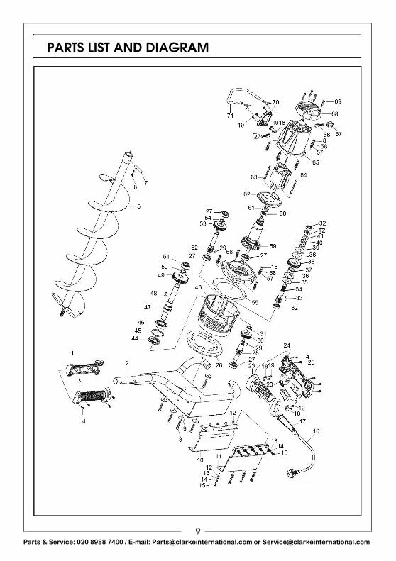
PARTS LIST AND DIAGRAM
9arts & Service: 020 8988 7400 / E-mail: [email protected] or [email protected]

P
ID DESCRIPTION PART NO ID DESCRIPTION PART NO
1 Left Handle Half WGCEA15001 37 Gear Sleeve WGCEA15037
2 Supporting Frame WGCEA15002 38 Gear WGCEA15038
3 Right Handle Half WGCEA15003 39 Upper Flange Washer WGCEA15039
4 Screw WGCEA15004 40 Coil Spring WGCEA15040
5 Auger Bit WGCEA15005 41 Spring Flange Washer WGCEA15041
6 Bolt WGCEA15006 42 Nut WGCEA15042
7 Pin WGCEA15007 43 Gear Casing WGCEA15043
8 Screw WGCEA15008 44 Oil Seal WGCEA15044
9 Washer WGCEA15009 45 Circlip WGCEA15045
10 Inner Cover Board WGCEA15010 46 Bearing WGCEA15046
11 Outer Cover Board WGCEA15011 47 Spindle WGCEA15047
12 Nut WGCEA15012 48 Woodruff Key WGCEA15048
13 Washer WGCEA15013 49 Drive Gear WGCEA15049
14 Spring Washer WGCEA15014 50 Circlip WGCEA15050
15 Screw WGCEA15015 51 Bearing WGCEA15051
16 Power Cable WGCEA15016 52 Gear Spindle WGCEA15052
17 Cable Gland WGCEA15017 53 Gear WGCEA15053
18 Cable Clamp WGCEA15018 54 Circlip WGCEA15054
19 Screw WGCEA15019 55 Oil-Proof Paper Seal WGCEA15055
20 Switch WGCEA15020 56 Centre Cover WGCEA15056
21 Switch Button WGCEA15021 57 Washer WGCEA15057
22 Capacitor WGCEA15022 58 Spring Washer WGCEA15058
23 Left Handle Half WGCEA15023 59 Rotor WGCEA15059
24 Right Handle Half WGCEA15024 60 Bearing WGCEA15060
25 Screw WGCEA15025 61 Bearing Cover WGCEA15061
26 Rubber Gasket WGCEA15026 62 Connecting Flange WGCEA15062
27 Bearing WGCEA15027 63 Screw WGCEA15063
28 Gear Spindle WGCEA15028 64 Stator WGCEA15064
29 Woodruff Key WGCEA15029 65 Motor Housing WGCEA15065
30 Drive Gear WGCEA15030 66 Carbon Brush WGCEA15066
31 Bearing WGCEA15031 67 Carbon Brush Holder WGCEA15067
32 Bearing WGCEA15032 68 Rear Cover WGCEA15068
33 Woodruff Key WGCEA15033 69 Screw WGCEA15069
34 Gear Spindle WGCEA15034 70 Safety Cover WGCEA15070
35 Lower Flange Washer WGCEA15035 71 Connecting Wire WGCEA15071
36 Friction Disc WGCEA15036
10arts & Service: 020 8988 7400 / E-mail: [email protected] or [email protected]

P
DECLARATION OF CONFORMITY
11arts & Service: 020 8988 7400 / E-mail: [email protected] or [email protected]