TAMA Brochure Cutting Table - Laser Cutting - Plasma Cutting/Oxygen Cutting #inspiredbyair
PRODUCT CATALOGUE
AUTOGENOUS TECHNOLOGY FOR STEEL
It‘s a GEGA
!

WELCOME TO GEGA WORLD. PRODUCT CATALOGUE
Welcome to the Gega world – welcome to the current edition of the Gega product catalogue.
This is your comprehensive guide throughout every field Gega is active in today and can be used as reliable reference when going to work with our equipment every day. We hope the detailed technical information on these pages will help you streamline maintenance- and procurement decisions, make the planning of service cycles more efficient and provide orientation when navigating through the large Gega spare parts and services portfolio.
This catalogue also stands testimony to fundamental Gega values; it is a clear statement about how we do things – and why. Gega is dedicated to providing “cutting edge” solutions to the steel industry, and we do so by striving to deliver products of ultimate precision, reliability and efficiency. In this sense, the catalogue, which you are holding in your hands right now, serves as a fine showcase of more than half a century of pushing boundaries to deliver excellence in our field of expertise.
Finally, and perhaps most importantly: What we are most proud of cannot be displayed in this catalogue at all. These are the countless Gega custom solutions, designed to meet specific challenges of our clients, which keep being deployed in production environments around the world. Finding these tailor-made solutions is amongst the founding principles of Gega – so please get in touch to discuss your individual needs. According to the motto: It´s a Gega !
With warm regards from Hofheim / Germany.
Christian Grosspointner Martin SalberCEO Gega Group CFO Gega Group


NOZZLESSDS FSDS FPSDS FBSHEL FHOTSTDSD3 HSOHFD 1FMBR
NOZZLES
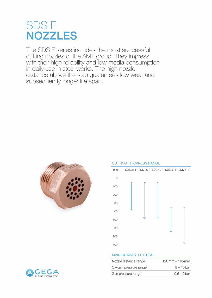
SDS FNOZZLESThe SDS F series includes the most successful cutting nozzles of the AMT group. They impress with their high reliability and low media consumption in daily use in steel works. The high nozzle distance above the slab guarantees low wear and subsequently longer life span.
Nozzle distance range 120 mm – 165 mm
Gas pressure range 0.6 – 2 bar
MAIN CHARACTERISTICS
Oxygen pressure range 8 – 15 bar
CUTTING THICKNESS RANGE
0
100
200
300
400
500
600
700
800
mm SDS 26 F SDS 36 F SDS 40 F SDS 51 F SDS 61 F
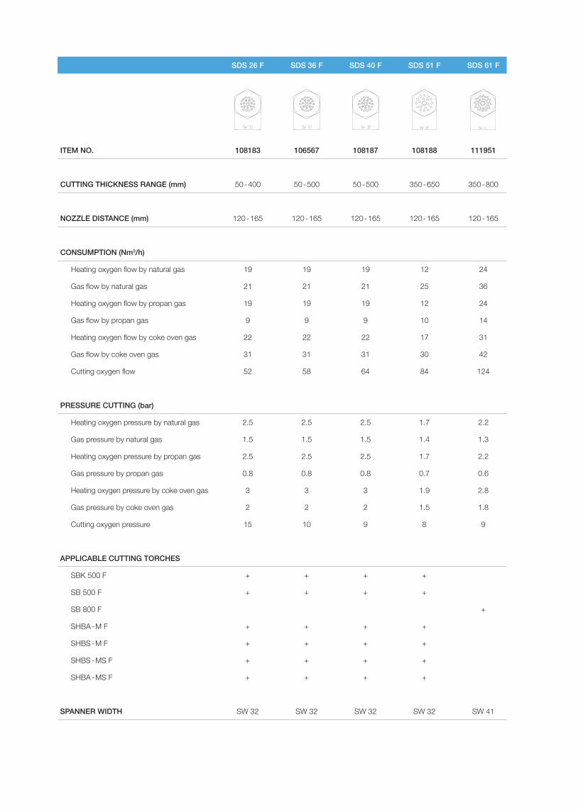
SDS 26 F SDS 36 F SDS 40 F SDS 51 F SDS 61 F
ITEM NO. 108183 106567 108187 108188 111951
CUTTING THICKNESS RANGE (mm) 50 - 400 50 - 500 50 - 500 350 - 650 350 - 800
NOZZLE DISTANCE (mm) 120 - 165 120 - 165 120 - 165 120 - 165 120 - 165
CONSUMPTION (Nm3/h)
Heating oxygen flow by natural gas 19 19 19 12 24
Gas flow by natural gas 21 21 21 25 36
Heating oxygen flow by propan gas 19 19 19 12 24
Gas flow by propan gas 9 9 9 10 14
Heating oxygen flow by coke oven gas 22 22 22 17 31
Gas flow by coke oven gas 31 31 31 30 42
Cutting oxygen flow 52 58 64 84 124
PRESSURE CUTTING (bar)
Heating oxygen pressure by natural gas 2.5 2.5 2.5 1.7 2.2
Gas pressure by natural gas 1.5 1.5 1.5 1.4 1.3
Heating oxygen pressure by propan gas 2.5 2.5 2.5 1.7 2.2
Gas pressure by propan gas 0.8 0.8 0.8 0.7 0.6
Heating oxygen pressure by coke oven gas 3 3 3 1.9 2.8
Gas pressure by coke oven gas 2 2 2 1.5 1.8
Cutting oxygen pressure 15 10 9 8 9
APPLICABLE CUTTING TORCHES
SBK 500 F + + + +
SB 500 F + + + +
SB 800 F +
SHBA - M F + + + +
SHBS - M F + + + +
SHBS - MS F + + + +
SHBA - MS F + + + +
SPANNER WIDTH SW 32 SW 32 SW 32 SW 32 SW 41
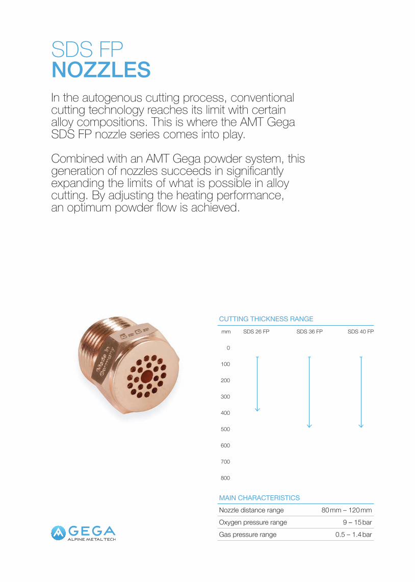
SDS FPNOZZLESIn the autogenous cutting process, conventional cutting technology reaches its limit with certain alloy compositions. This is where the AMT Gega SDS FP nozzle series comes into play.
Combined with an AMT Gega powder system, this generation of nozzles succeeds in significantly expanding the limits of what is possible in alloy cutting. By adjusting the heating performance, an optimum powder flow is achieved.
Nozzle distance range 80 mm – 120 mm
Gas pressure range 0.5 – 1.4 bar
MAIN CHARACTERISTICS
Oxygen pressure range 9 – 15 bar
0
100
200
300
400
500
600
700
800
mm SDS 26 FP SDS 36 FP SDS 40 FP
CUTTING THICKNESS RANGE
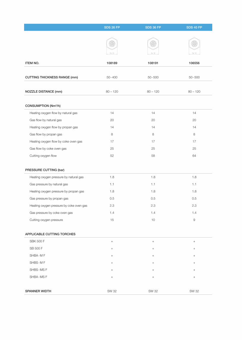
SDS 26 FP SDS 36 FP SDS 40 FP
ITEM NO. 108189 108191 106556
CUTTING THICKNESS RANGE (mm) 50 - 400 50 - 500 50 - 500
NOZZLE DISTANCE (mm) 80 – 120 80 – 120 80 – 120
CONSUMPTION (Nm3/h)
Heating oxygen flow by natural gas 14 14 14
Gas flow by natural gas 20 20 20
Heating oxygen flow by propan gas 14 14 14
Gas flow by propan gas 8 8 8
Heating oxygen flow by coke oven gas 17 17 17
Gas flow by coke oven gas 25 25 25
Cutting oxygen flow 52 58 64
PRESSURE CUTTING (bar)
Heating oxygen pressure by natural gas 1.8 1.8 1.8
Gas pressure by natural gas 1.1 1.1 1.1
Heating oxygen pressure by propan gas 1.8 1.8 1.8
Gas pressure by propan gas 0.5 0.5 0.5
Heating oxygen pressure by coke oven gas 2.3 2.3 2.3
Gas pressure by coke oven gas 1.4 1.4 1.4
Cutting oxygen pressure 15 10 9
APPLICABLE CUTTING TORCHES
SBK 500 F + + +
SB 500 F + + +
SHBA - M F + + +
SHBS - M F + + +
SHBS - MS F + + +
SHBA - MS F + + +
SPANNER WIDTH SW 32 SW 32 SW 32
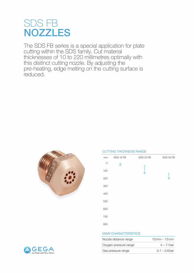
SDS FBNOZZLESThe SDS FB series is a special application for plate cutting within the SDS family. Cut material thicknesses of 10 to 220 millimetres optimally with this distinct cutting nozzle. By adjusting the pre-heating, edge melting on the cutting surface is reduced.
Nozzle distance range 10 mm – 15 mm
Gas pressure range 0.1 – 0.6 bar
MAIN CHARACTERISTICS
Oxygen pressure range 4 – 11 bar
0
100
200
300
400
500
600
700
800
mm SDS 18 FB SDS 23 FB SDS 30 FB
CUTTING THICKNESS RANGE
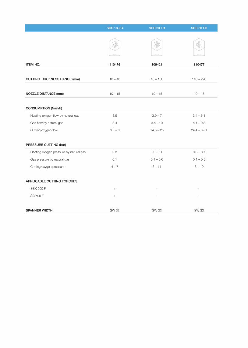
SDS 18 FB SDS 23 FB SDS 30 FB
ITEM NO. 110476 109421 110477
CUTTING THICKNESS RANGE (mm) 10 – 40 40 – 150 140 – 220
NOZZLE DISTANCE (mm) 10 – 15 10 – 15 10 – 15
CONSUMPTION (Nm3/h)
Heating oxygen flow by natural gas 3.9 3.9 – 7 3.4 – 5.1
Gas flow by natural gas 3.4 3.4 – 10 4.1 – 9.3
Cutting oxygen flow 6.8 – 8 14.6 – 25 24.4 – 39.1
PRESSURE CUTTING (bar)
Heating oxygen pressure by natural gas 0.3 0.3 – 0.8 0.3 – 0.7
Gas pressure by natural gas 0.1 0.1 – 0.6 0.1 – 0.5
Cutting oxygen pressure 4 – 7 6 – 11 6 – 10
APPLICABLE CUTTING TORCHES
SBK 500 F + + +
SB 500 F + + +
SPANNER WIDTH SW 32 SW 32 SW 32
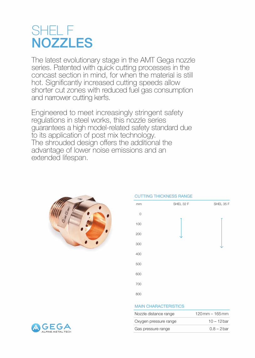
SHEL FNOZZLESThe latest evolutionary stage in the AMT Gega nozzle series. Patented with quick cutting processes in the concast section in mind, for when the material is still hot. Significantly increased cutting speeds allow shorter cut zones with reduced fuel gas consumption and narrower cutting kerfs.
Engineered to meet increasingly stringent safety regulations in steel works, this nozzle series guarantees a high model-related safety standard due to its application of post mix technology. The shrouded design offers the additional the advantage of lower noise emissions and an extended lifespan.
Nozzle distance range 120 mm – 165 mm
Gas pressure range 0.8 – 2 bar
MAIN CHARACTERISTICS
Oxygen pressure range 10 – 12 bar
0
100
200
300
400
500
600
700
800
mm SHEL 32 F SHEL 35 F
CUTTING THICKNESS RANGE

SHEL 32 F SHEL 35 F
ITEM NO. 111893 111892
CUTTING THICKNESS RANGE (mm) 50 – 250 50 – 350
NOZZLE DISTANCE (mm) 120 – 165 120 – 165
CONSUMPTION (Nm3/h)
Heating oxygen flow by natural gas 22 22
Gas flow by natural gas 17 17
Heating oxygen flow by propan gas 22 22
Gas flow by propan gas 7.5 7.5
Heating oxygen flow by coke oven gas 25 25
Gas flow by coke oven gas 23 23
Cutting oxygen flow 53 53
PRESSURE CUTTING (bar)
Heating oxygen pressure by natural gas 2.5 2.5
Gas pressure by natural gas 1.5 1.5
Heating oxygen pressure by propan gas 2.5 2.5
Gas pressure by propan gas 0.8 0.8
Heating oxygen pressure by coke oven gas 3 3
Gas pressure by coke oven gas 2 2
Cutting oxygen pressure 12 10
APPLICABLE CUTTING TORCHES
SBK 500 F + +
SB 500 F + +
SHBA - M F + +
SHBS - M F + +
SHBS - MS F + +
SHBA - MS F + +
SPANNER WIDTH SW 36 SW 36
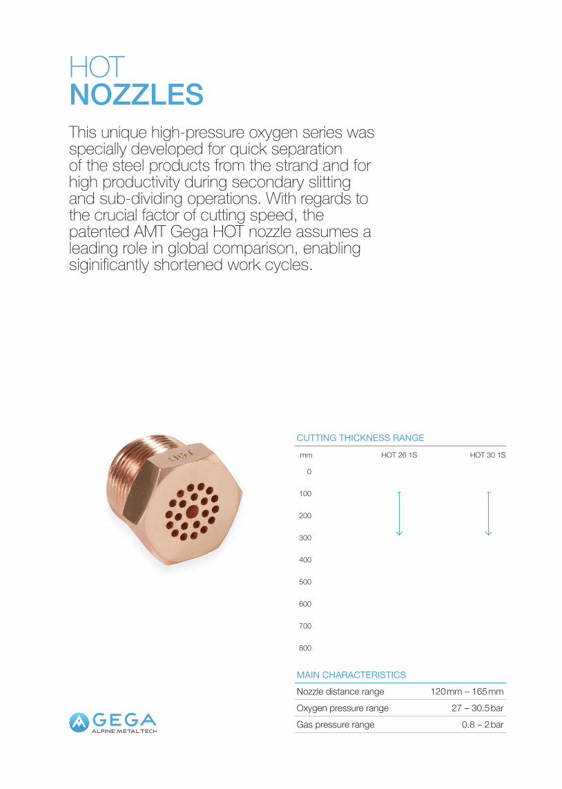
HOTNOZZLESThis unique high-pressure oxygen series was specially developed for quick separation of the steel products from the strand and for high productivity during secondary slitting and sub-dividing operations. With regards to the crucial factor of cutting speed, the patented AMT Gega HOT nozzle assumes a leading role in global comparison, enabling siginificantly shortened work cycles.
Nozzle distance range 120 mm – 165 mm
Gas pressure range 0.8 – 2 bar
MAIN CHARACTERISTICS
Oxygen pressure range 27 – 30.5 bar
0
100
200
300
400
500
600
700
800
mm HOT 26 1S HOT 30 1S
CUTTING THICKNESS RANGE
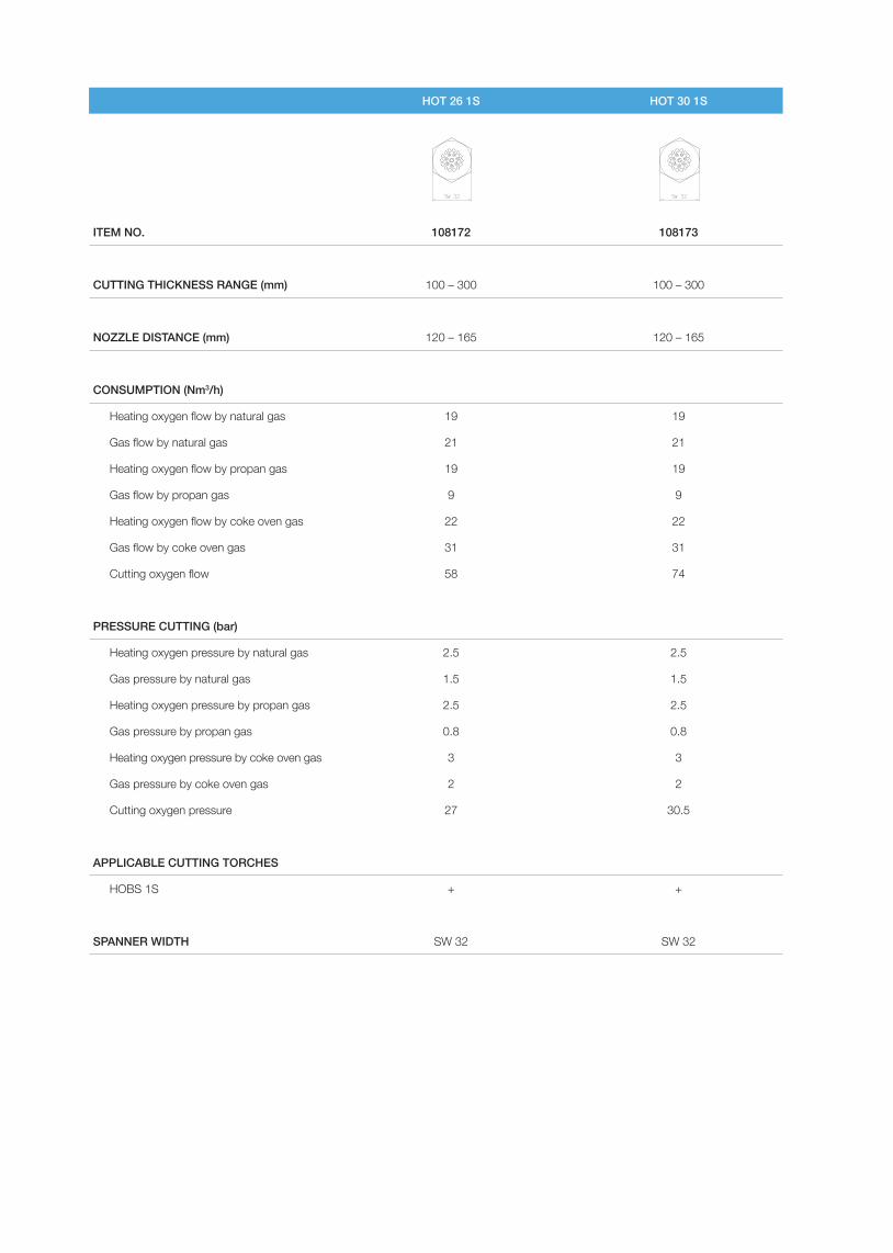
HOT 26 1S HOT 30 1S
ITEM NO. 108172 108173
CUTTING THICKNESS RANGE (mm) 100 – 300 100 – 300
NOZZLE DISTANCE (mm) 120 – 165 120 – 165
CONSUMPTION (Nm3/h)
Heating oxygen flow by natural gas 19 19
Gas flow by natural gas 21 21
Heating oxygen flow by propan gas 19 19
Gas flow by propan gas 9 9
Heating oxygen flow by coke oven gas 22 22
Gas flow by coke oven gas 31 31
Cutting oxygen flow 58 74
PRESSURE CUTTING (bar)
Heating oxygen pressure by natural gas 2.5 2.5
Gas pressure by natural gas 1.5 1.5
Heating oxygen pressure by propan gas 2.5 2.5
Gas pressure by propan gas 0.8 0.8
Heating oxygen pressure by coke oven gas 3 3
Gas pressure by coke oven gas 2 2
Cutting oxygen pressure 27 30.5
APPLICABLE CUTTING TORCHES
HOBS 1S + +
SPANNER WIDTH SW 32 SW 32
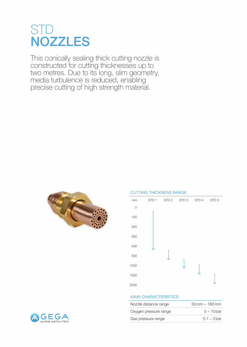
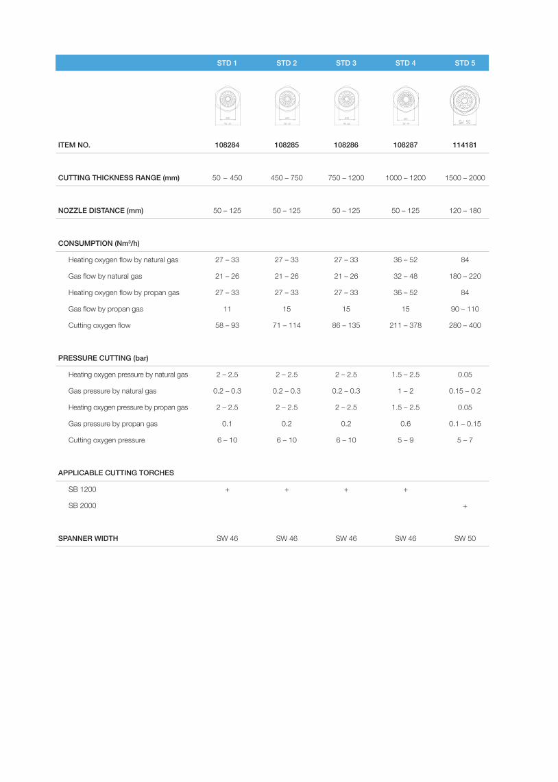
STDNOZZLESThis conically sealing thick cutting nozzle is constructed for cutting thicknesses up to two metres. Due to its long, slim geometry, media turbulence is reduced, enabling precise cutting of high strength material.
Nozzle distance range 50 mm – 180 mm
Gas pressure range 0.1 – 2 bar
MAIN CHARACTERISTICS
Oxygen pressure range 5 – 10 bar
0
100
200
300
400
500
1000
1500
2000
mm STD 1 STD 2 STD 3 STD 4 STD 5
CUTTING THICKNESS RANGE
STD 1 STD 2 STD 3 STD 4 STD 5
ITEM NO. 108284 108285 108286 108287 114181
CUTTING THICKNESS RANGE (mm) 50 – 450 450 – 750 750 – 1200 1000 – 1200 1500 – 2000
NOZZLE DISTANCE (mm) 50 – 125 50 – 125 50 – 125 50 – 125 120 – 180
CONSUMPTION (Nm3/h)
Heating oxygen flow by natural gas 27 – 33 27 – 33 27 – 33 36 – 52 84
Gas flow by natural gas 21 – 26 21 – 26 21 – 26 32 – 48 180 – 220
Heating oxygen flow by propan gas 27 – 33 27 – 33 27 – 33 36 – 52 84
Gas flow by propan gas 11 15 15 15 90 – 110
Cutting oxygen flow 58 – 93 71 – 114 86 – 135 211 – 378 280 – 400
PRESSURE CUTTING (bar)
Heating oxygen pressure by natural gas 2 – 2.5 2 – 2.5 2 – 2.5 1.5 – 2.5 0.05
Gas pressure by natural gas 0.2 – 0.3 0.2 – 0.3 0.2 – 0.3 1 – 2 0.15 – 0.2
Heating oxygen pressure by propan gas 2 – 2.5 2 – 2.5 2 – 2.5 1.5 – 2.5 0.05
Gas pressure by propan gas 0.1 0.2 0.2 0.6 0.1 – 0.15
Cutting oxygen pressure 6 – 10 6 – 10 6 – 10 5 – 9 5 – 7
APPLICABLE CUTTING TORCHES
SB 1200 + + + +
SB 2000 +
SPANNER WIDTH SW 46 SW 46 SW 46 SW 46 SW 50
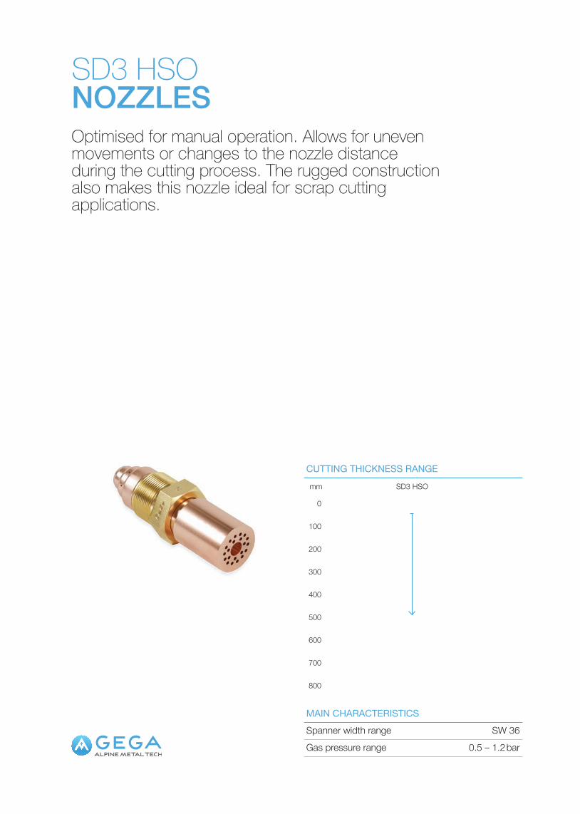
SD3 HSONOZZLESOptimised for manual operation. Allows for uneven movements or changes to the nozzle distance during the cutting process. The rugged construction also makes this nozzle ideal for scrap cutting applications.
Spanner width range SW 36MAIN CHARACTERISTICS
Gas pressure range 0.5 – 1.2 bar
0
100
200
300
400
500
600
700
800
mm SD3 HSO
CUTTING THICKNESS RANGE
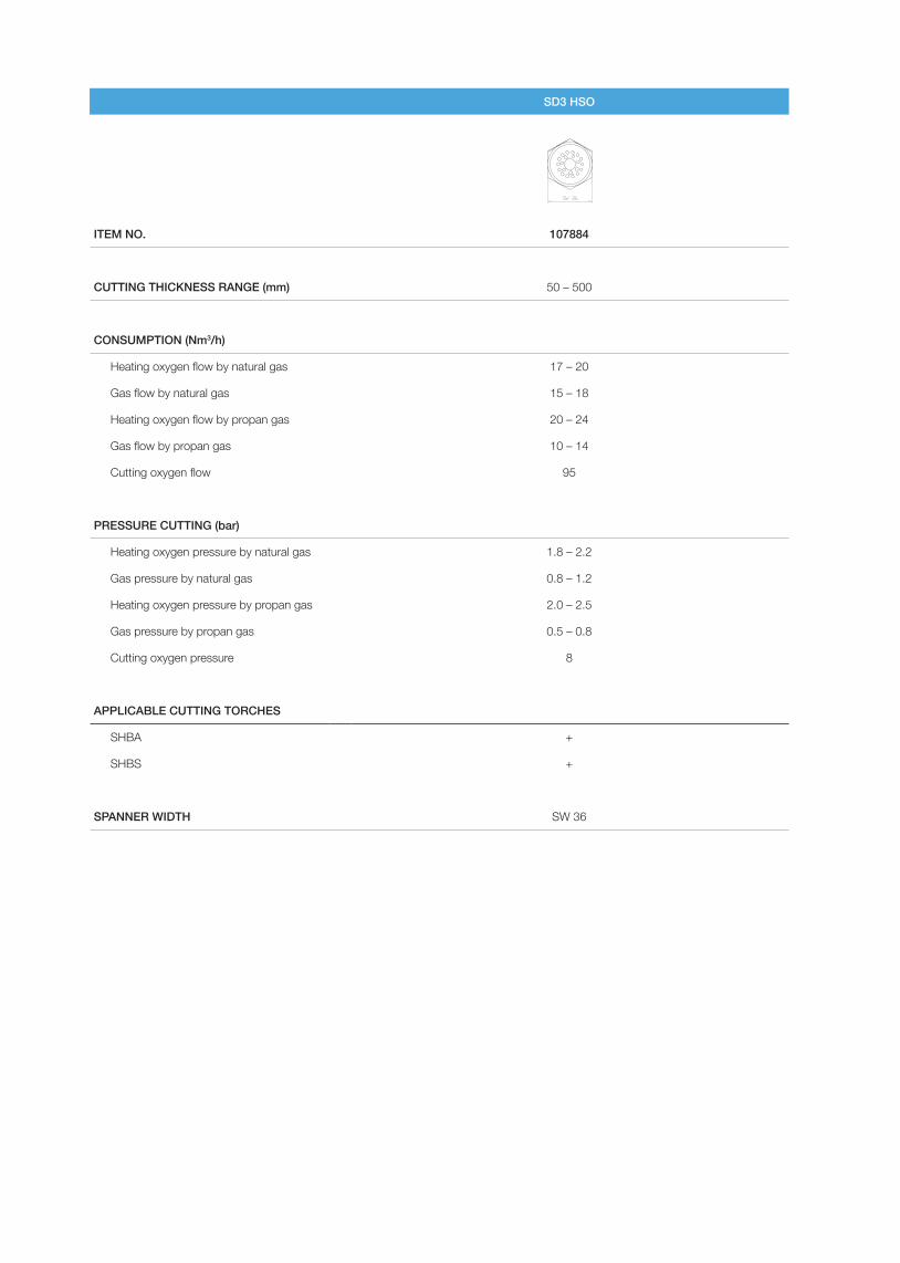
SD3 HSO
ITEM NO. 107884
CUTTING THICKNESS RANGE (mm) 50 – 500
CONSUMPTION (Nm3/h)
Heating oxygen flow by natural gas 17 – 20
Gas flow by natural gas 15 – 18
Heating oxygen flow by propan gas 20 – 24
Gas flow by propan gas 10 – 14
Cutting oxygen flow 95
PRESSURE CUTTING (bar)
Heating oxygen pressure by natural gas 1.8 – 2.2
Gas pressure by natural gas 0.8 – 1.2
Heating oxygen pressure by propan gas 2.0 – 2.5
Gas pressure by propan gas 0.5 – 0.8
Cutting oxygen pressure 8
APPLICABLE CUTTING TORCHES
SHBA +
SHBS +
SPANNER WIDTH SW 36
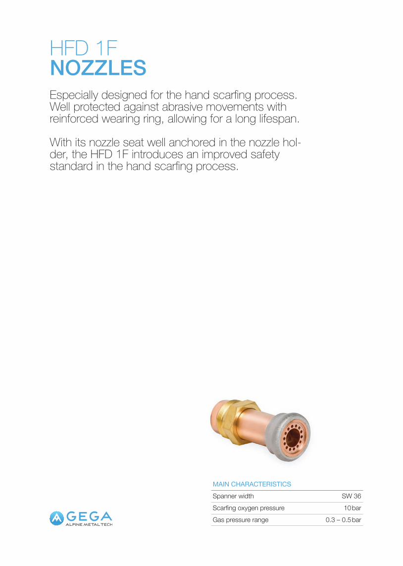
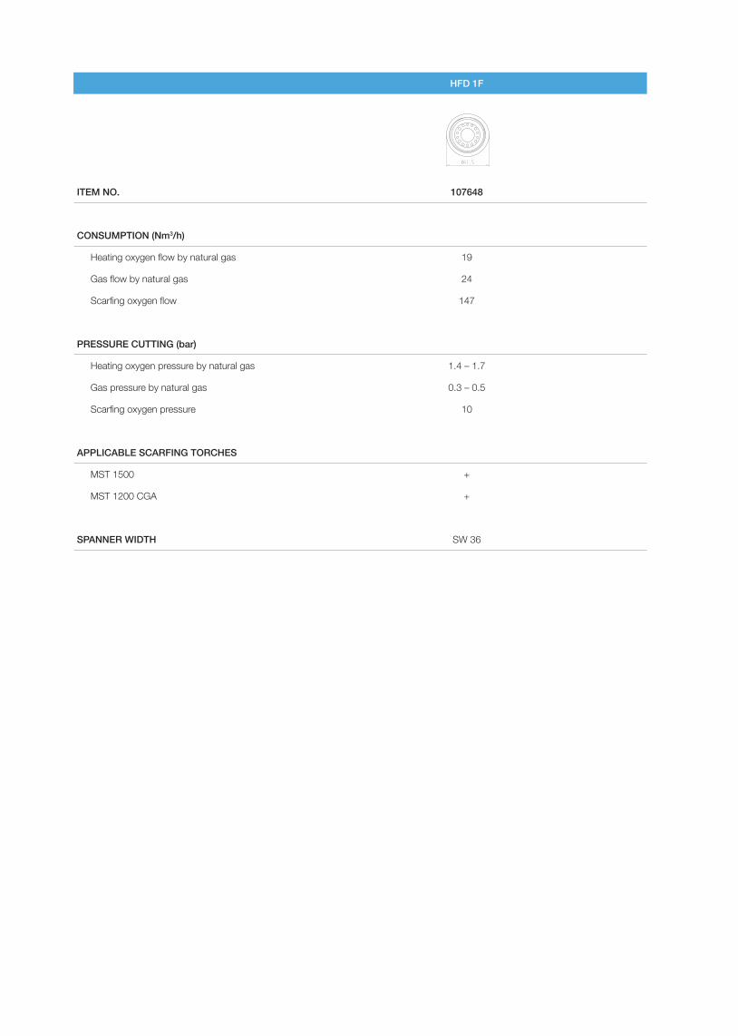
HFD 1FNOZZLESEspecially designed for the hand scarfing process. Well protected against abrasive movements with reinforced wearing ring, allowing for a long lifespan.
With its nozzle seat well anchored in the nozzle hol-der, the HFD 1F introduces an improved safety standard in the hand scarfing process.
Spanner width SW 36Scarfing oxygen pressure 10 barGas pressure range 0.3 – 0.5 bar
MAIN CHARACTERISTICS
HFD 1F
ITEM NO. 107648
CONSUMPTION (Nm3/h)
Heating oxygen flow by natural gas 19
Gas flow by natural gas 24
Scarfing oxygen flow 147
PRESSURE CUTTING (bar)
Heating oxygen pressure by natural gas 1.4 – 1.7
Gas pressure by natural gas 0.3 – 0.5
Scarfing oxygen pressure 10
APPLICABLE SCARFING TORCHES
MST 1500 +
MST 1200 CGA +
SPANNER WIDTH SW 36
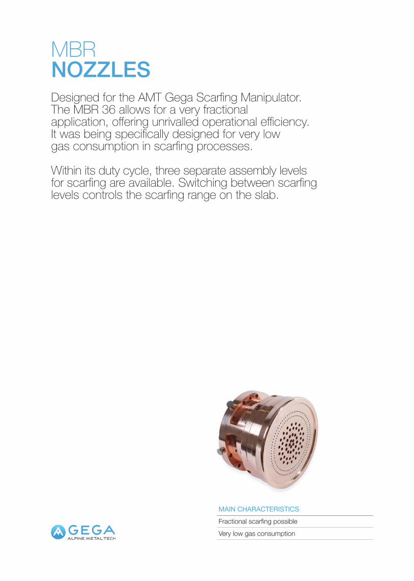
MBRNOZZLESDesigned for the AMT Gega Scarfing Manipulator. The MBR 36 allows for a very fractional application, offering unrivalled operational efficiency. It was being specifically designed for very low gas consumption in scarfing processes.
Within its duty cycle, three separate assembly levels for scarfing are available. Switching between scarfing levels controls the scarfing range on the slab.
Fractional scarfing possibleVery low gas consumption
MAIN CHARACTERISTICS
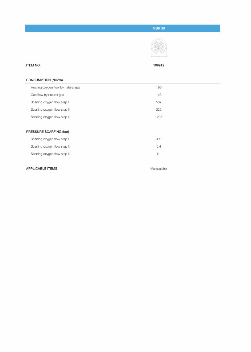
MBR 36
ITEM NO. 109912
CONSUMPTION (Nm3/h)
Heating oxygen flow by natural gas 190
Gas flow by natural gas 148
Scarfing oxygen flow step I 587
Scarfing oxygen flow step II 326
Scarfing oxygen flow step III 1235
PRESSURE SCARFING (bar)
Scarfing oxygen flow step I 4.5
Scarfing oxygen flow step II 0.4
Scarfing oxygen flow step III 1.1
APPLICABLE ITEMS Manipulator

TORCHESSB– SB 500 F– SB 800 F– SB 1200– SB 2000HOBS 1SSBKSHBS / SHBASHBS-M(S) F / SHBA-M(S) FIgnition Burner
TORCHES
SBTORCHESThe AMT Group SB torch range is a benchmark product in cutting technology. With the inner workings of the torch well shielded against the environment, long operating cycles are made possible. AMT Gega nozzle holders can be main-tained on site and with little effort by use of a special seat re-cutting tool. Water cooling of the nozzle holder itself increases the lifespan of the cutting nozzle even further.

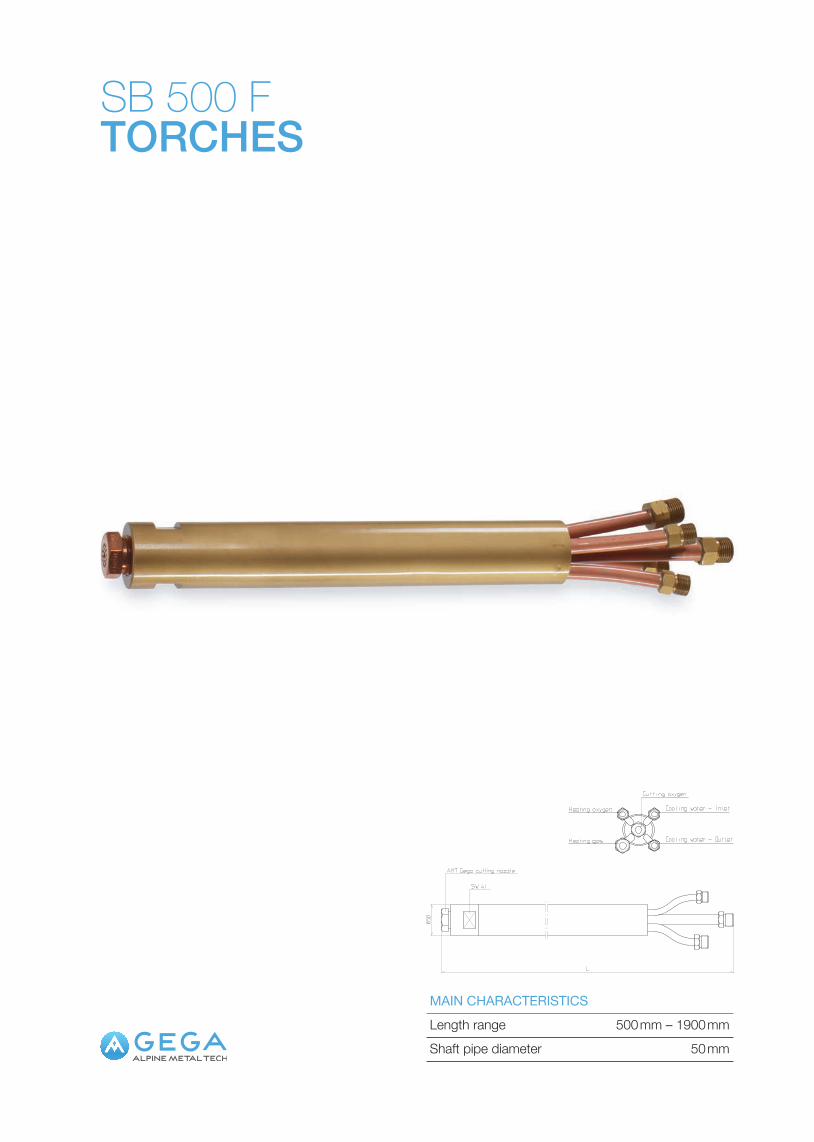
SB 500 FTORCHES
Length range 500 mm – 1900 mmMAIN CHARACTERISTICS
Shaft pipe diameter 50 mm
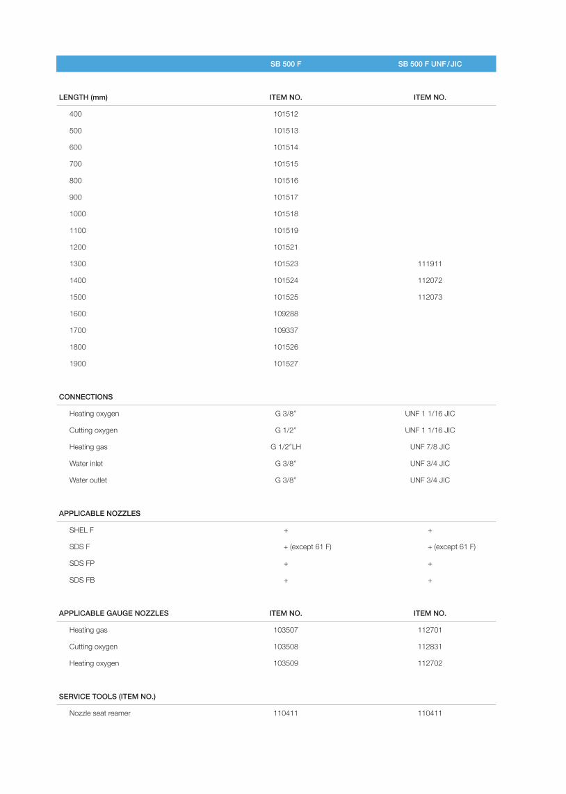
SB 500 F SB 500 F UNF / JIC
LENGTH (mm) ITEM NO. ITEM NO.
400 101512
500 101513
600 101514
700 101515
800 101516
900 101517
1000 101518
1100 101519
1200 101521
1300 101523 111911
1400 101524 112072
1500 101525 112073
1600 109288
1700 109337
1800 101526
1900 101527
CONNECTIONS
Heating oxygen G 3/8″ UNF 1 1/16 JIC
Cutting oxygen G 1/2″ UNF 1 1/16 JIC
Heating gas G 1/2″LH UNF 7/8 JIC
Water inlet G 3/8″ UNF 3/4 JIC
Water outlet G 3/8″ UNF 3/4 JIC
APPLICABLE NOZZLES
SHEL F + +
SDS F + (except 61 F) + (except 61 F)
SDS FP + +
SDS FB + +
APPLICABLE GAUGE NOZZLES ITEM NO. ITEM NO.
Heating gas 103507 112701
Cutting oxygen 103508 112831
Heating oxygen 103509 112702
SERVICE TOOLS (ITEM NO.)
Nozzle seat reamer 110411 110411
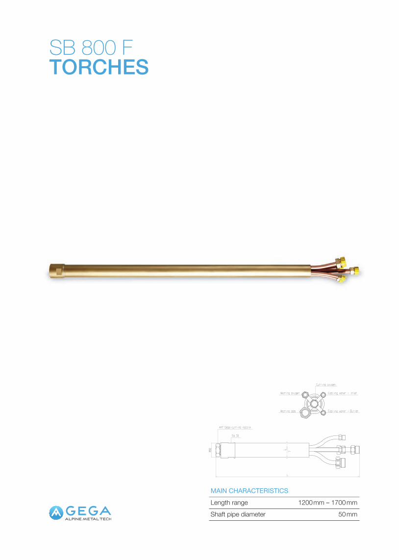
SB 800 FTORCHES
Length range 1200 mm – 1700 mmMAIN CHARACTERISTICS
Shaft pipe diameter 50 mm
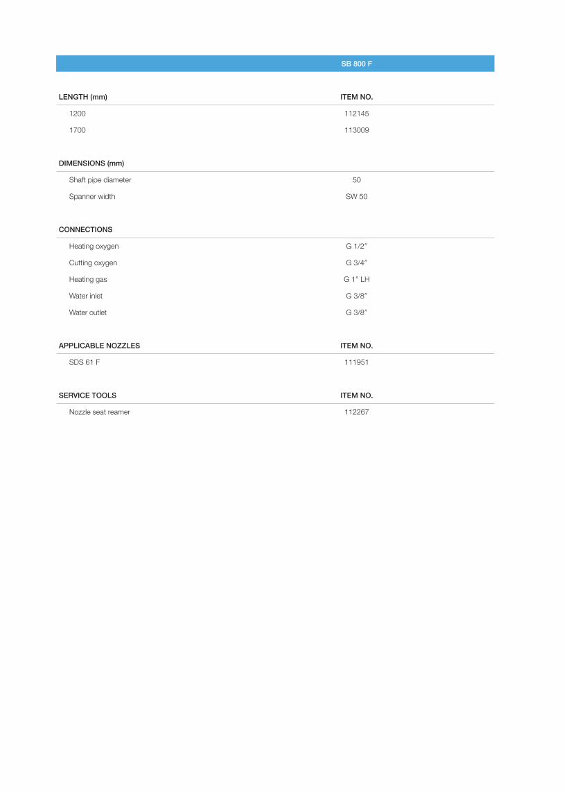
SB 800 F
LENGTH (mm) ITEM NO.
1200 112145
1700 113009
DIMENSIONS (mm)
Shaft pipe diameter 50
Spanner width SW 50
CONNECTIONS
Heating oxygen G 1/2″
Cutting oxygen G 3/4″
Heating gas G 1″ LH
Water inlet G 3/8″
Water outlet G 3/8″
APPLICABLE NOZZLES ITEM NO.
SDS 61 F 111951
SERVICE TOOLS ITEM NO.
Nozzle seat reamer 112267
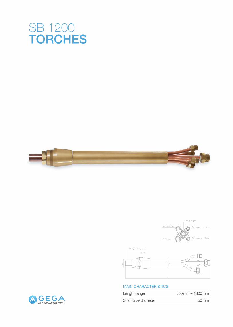
SB 1200TORCHES
Length range 500 mm – 1800 mmMAIN CHARACTERISTICS
Shaft pipe diameter 50 mm
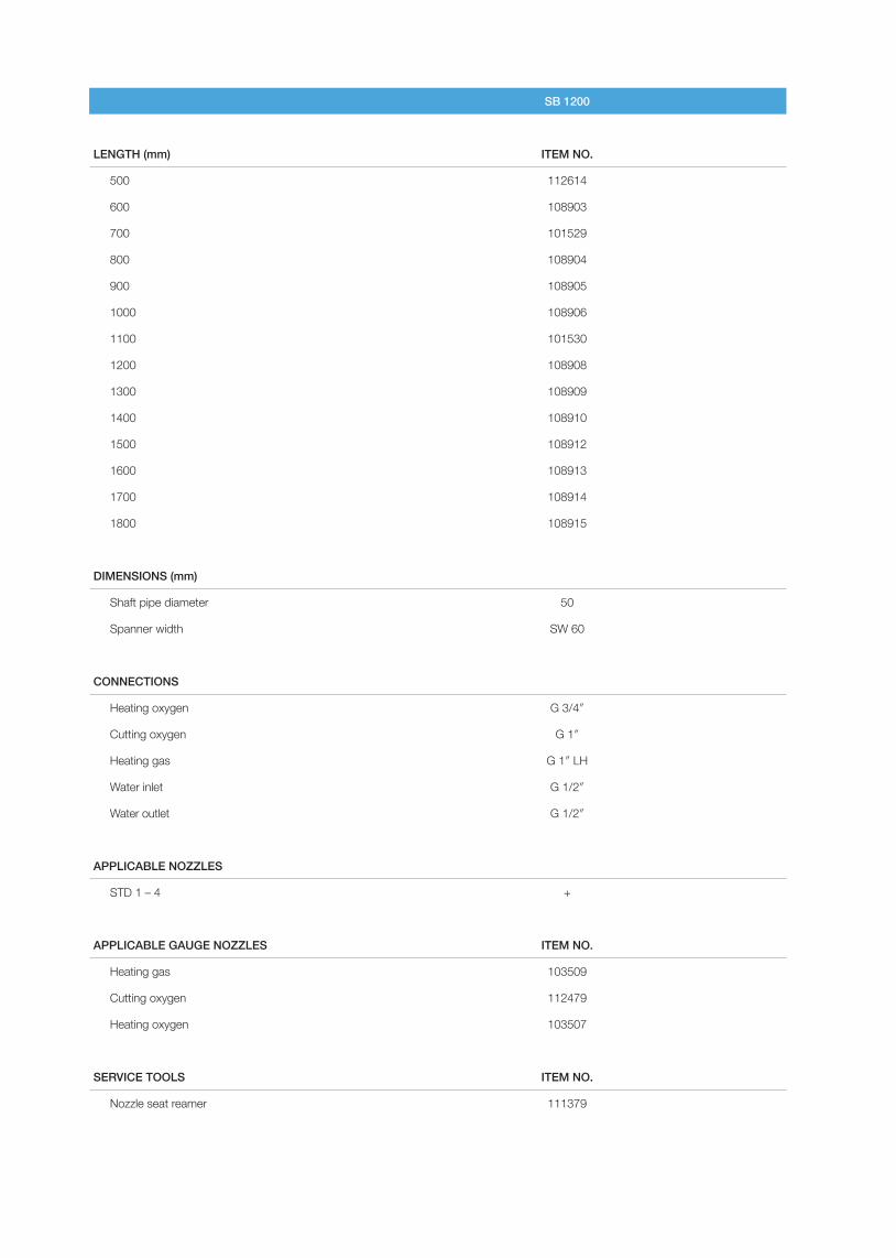
SB 1200
LENGTH (mm) ITEM NO.
500 112614
600 108903
700 101529
800 108904
900 108905
1000 108906
1100 101530
1200 108908
1300 108909
1400 108910
1500 108912
1600 108913
1700 108914
1800 108915
DIMENSIONS (mm)
Shaft pipe diameter 50
Spanner width SW 60
CONNECTIONS
Heating oxygen G 3/4″
Cutting oxygen G 1″
Heating gas G 1″ LH
Water inlet G 1/2″
Water outlet G 1/2″
APPLICABLE NOZZLES
STD 1 – 4 +
APPLICABLE GAUGE NOZZLES ITEM NO.
Heating gas 103509
Cutting oxygen 112479
Heating oxygen 103507
SERVICE TOOLS ITEM NO.
Nozzle seat reamer 111379
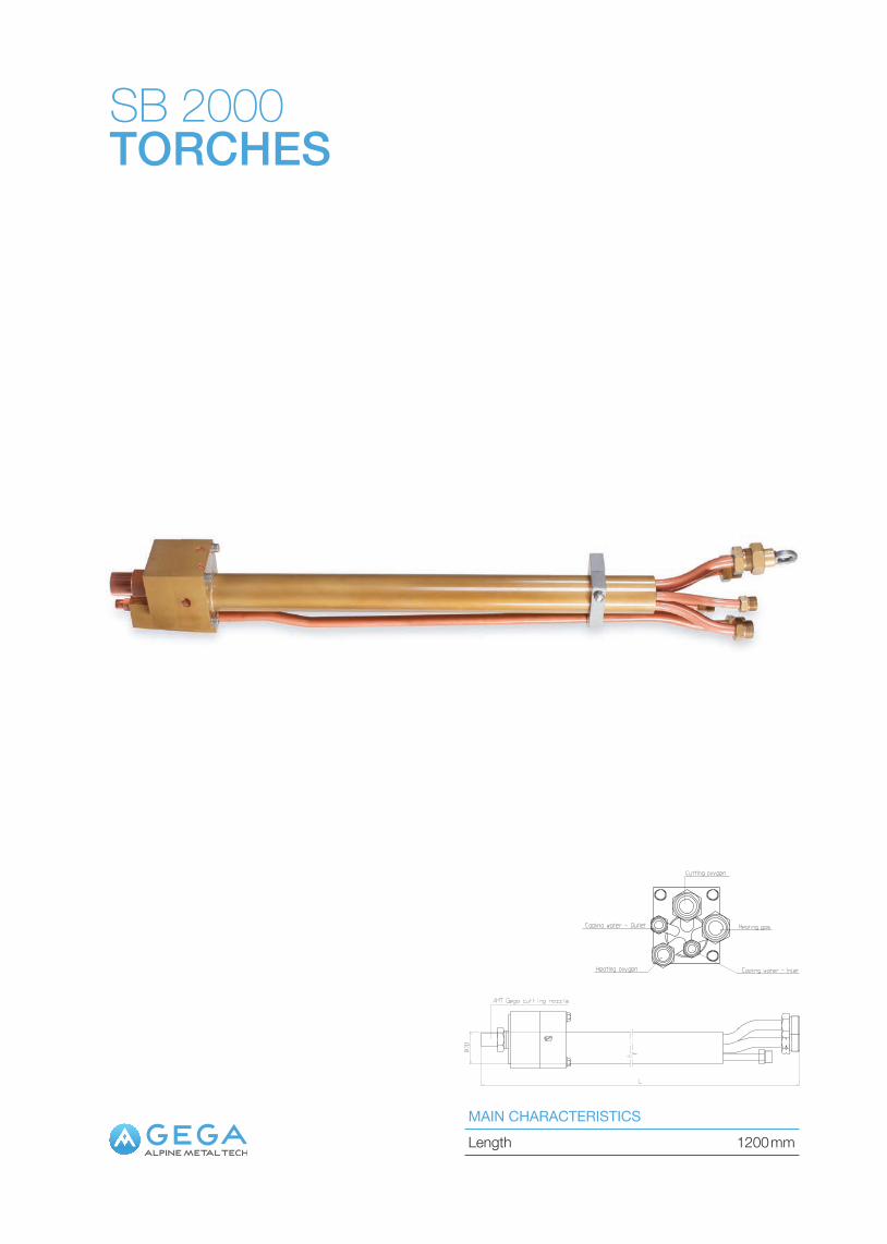
SB 2000TORCHES
Length 1200 mmMAIN CHARACTERISTICS
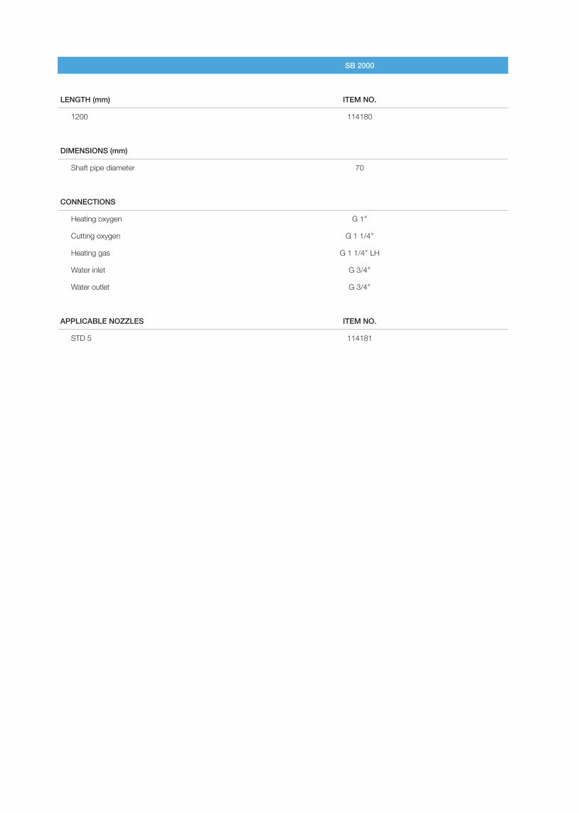
SB 2000
LENGTH (mm) ITEM NO.
1200 114180
DIMENSIONS (mm)
Shaft pipe diameter 70
CONNECTIONS
Heating oxygen G 1″
Cutting oxygen G 1 1/4″
Heating gas G 1 1/4″ LH
Water inlet G 3/4″
Water outlet G 3/4″
APPLICABLE NOZZLES ITEM NO.
STD 5 114181
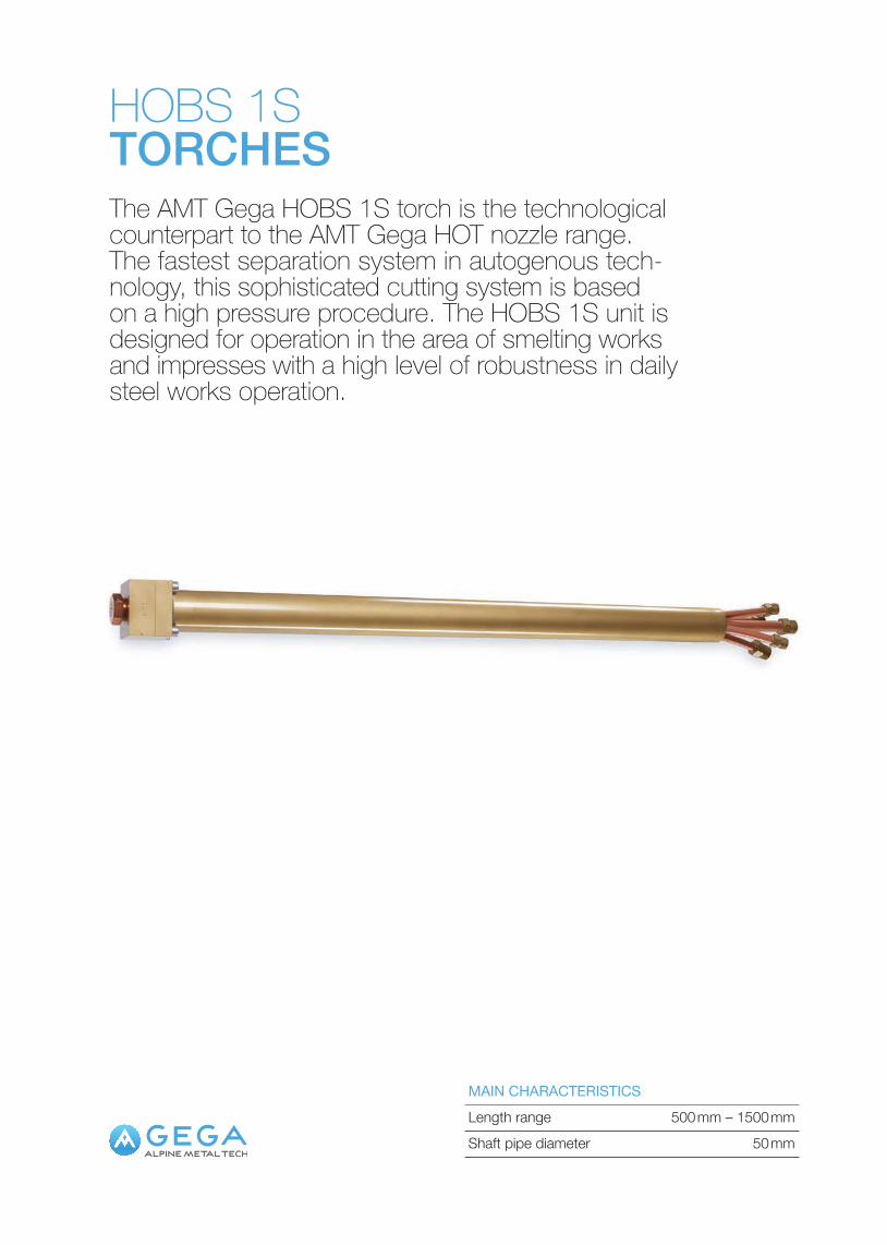
HOBS 1STORCHESThe AMT Gega HOBS 1S torch is the technological counterpart to the AMT Gega HOT nozzle range. The fastest separation system in autogenous tech-nology, this sophisticated cutting system is based on a high pressure procedure. The HOBS 1S unit is designed for operation in the area of smelting works and impresses with a high level of robustness in daily steel works operation.
Length range 500 mm – 1500 mmMAIN CHARACTERISTICS
Shaft pipe diameter 50 mm
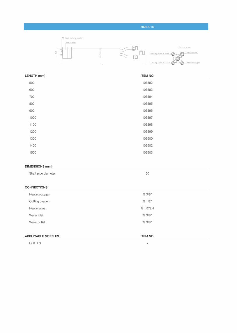
HOBS 1S
LENGTH (mm) ITEM NO.
500 106892
600 106893
700 106894
800 106895
900 106896
1000 106897
1100 106898
1200 106899
1300 106900
1400 106902
1500 106903
DIMENSIONS (mm)
Shaft pipe diameter 50
CONNECTIONS
Heating oxygen G 3/8″
Cutting oxygen G 1/2″
Heating gas G 1/2″LH
Water inlet G 3/8″
Water outlet G 3/8″
APPLICABLE NOZZLES ITEM NO.
HOT 1 S +
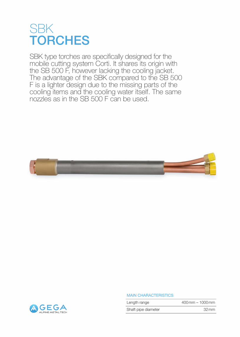
SBKTORCHESSBK type torches are specifically designed for the mobile cutting system Corti. It shares its origin with the SB 500 F, however lacking the cooling jacket. The advantage of the SBK compared to the SB 500 F is a lighter design due to the missing parts of the cooling items and the cooling water itself. The same nozzles as in the SB 500 F can be used.
Length range 400 mm – 1000 mmMAIN CHARACTERISTICS
Shaft pipe diameter 32 mm
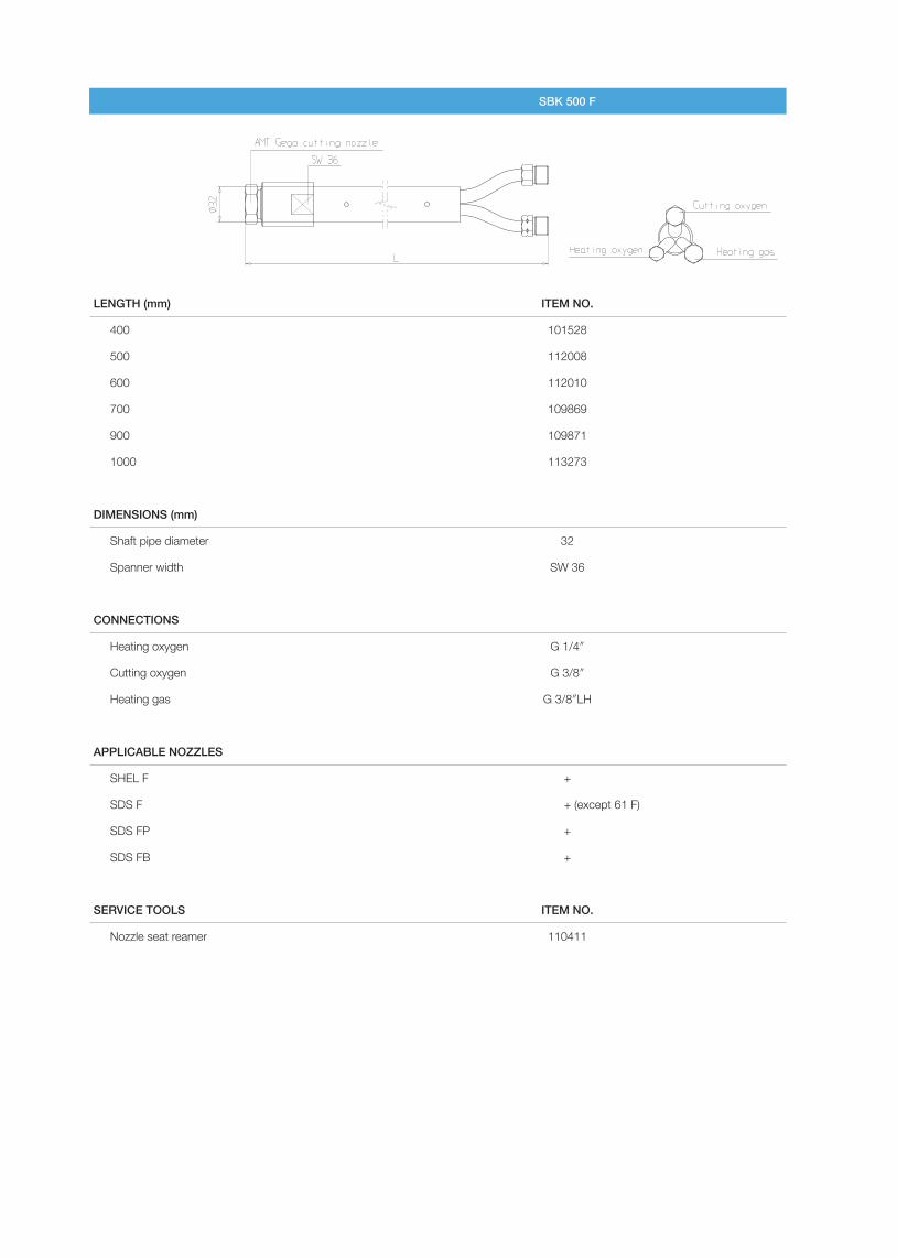
SBK 500 F
LENGTH (mm) ITEM NO.
400 101528
500 112008
600 112010
700 109869
900 109871
1000 113273
DIMENSIONS (mm)
Shaft pipe diameter 32
Spanner width SW 36
CONNECTIONS
Heating oxygen G 1/4″
Cutting oxygen G 3/8″
Heating gas G 3/8″LH
APPLICABLE NOZZLES
SHEL F +
SDS F + (except 61 F)
SDS FP +
SDS FB +
SERVICE TOOLS ITEM NO.
Nozzle seat reamer 110411
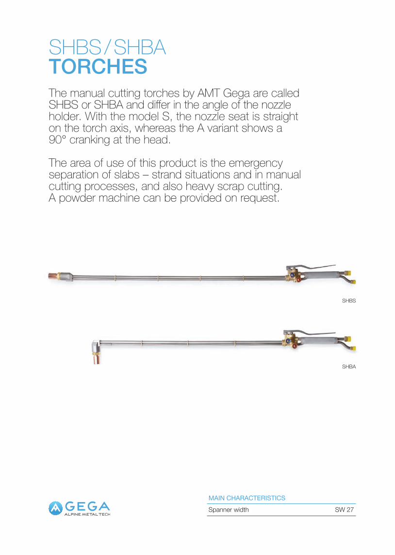
SHBS / SHBATORCHESThe manual cutting torches by AMT Gega are called SHBS or SHBA and differ in the angle of the nozzle holder. With the model S, the nozzle seat is straight on the torch axis, whereas the A variant shows a 90° cranking at the head.
The area of use of this product is the emergency separation of slabs – strand situations and in manual cutting processes, and also heavy scrap cutting. A powder machine can be provided on request.
MAIN CHARACTERISTICS
SHBS
SHBA
Spanner width SW 27
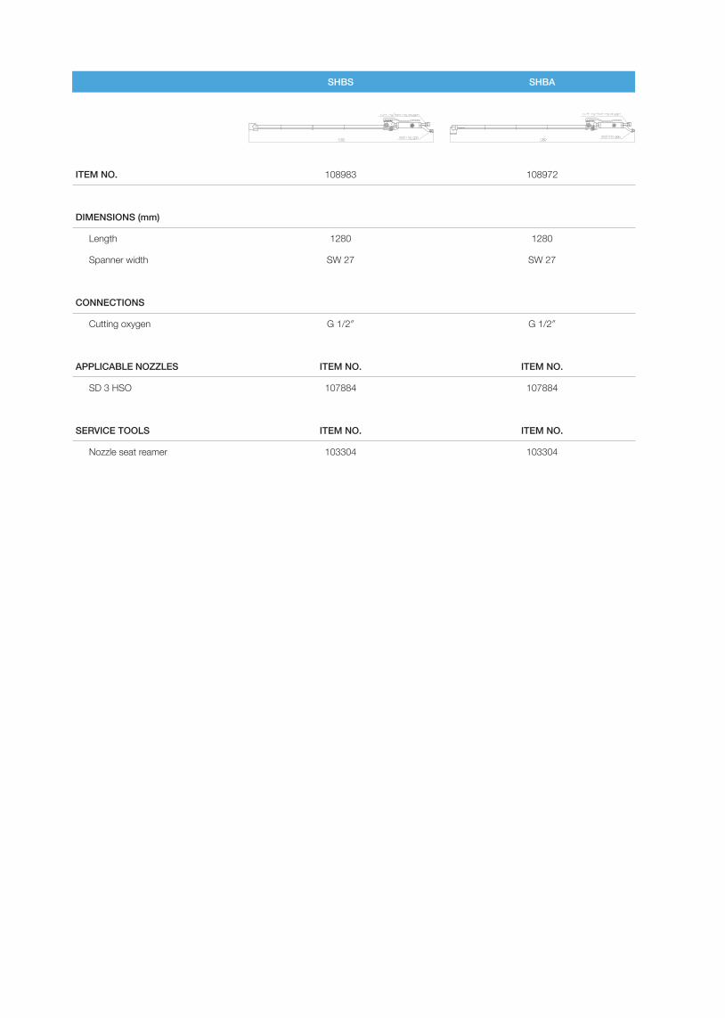
SHBS SHBA
ITEM NO. 108983 108972
DIMENSIONS (mm)
Length 1280 1280
Spanner width SW 27 SW 27
CONNECTIONS
Cutting oxygen G 1/2″ G 1/2″
APPLICABLE NOZZLES ITEM NO. ITEM NO.
SD 3 HSO 107884 107884
SERVICE TOOLS ITEM NO. ITEM NO.
Nozzle seat reamer 103304 103304
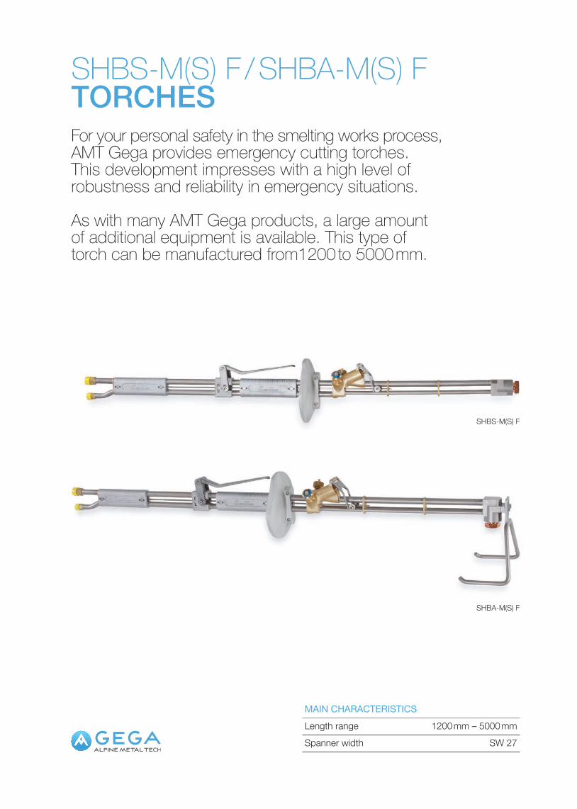
SHBS-M(S) F / SHBA-M(S) FTORCHESFor your personal safety in the smelting works process, AMT Gega provides emergency cutting torches. This development impresses with a high level of robustness and reliability in emergency situations.
As with many AMT Gega products, a large amount of additional equipment is available. This type of torch can be manufactured from1200 to 5000 mm.
Length range 1200 mm – 5000 mmMAIN CHARACTERISTICS
Spanner width SW 27
SHBS-M(S) F
SHBA-M(S) F
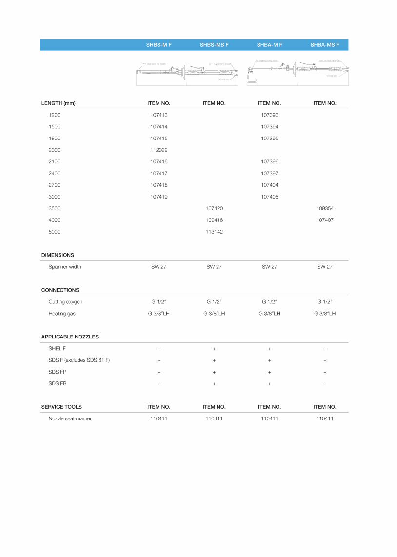
SHBS-M F SHBS-MS F SHBA-M F SHBA-MS F
LENGTH (mm) ITEM NO. ITEM NO. ITEM NO. ITEM NO.
1200 107413 107393
1500 107414 107394
1800 107415 107395
2000 112022
2100 107416 107396
2400 107417 107397
2700 107418 107404
3000 107419 107405
3500 107420 109354
4000 109418 107407
5000 113142
DIMENSIONS
Spanner width SW 27 SW 27 SW 27 SW 27
CONNECTIONS
Cutting oxygen G 1/2″ G 1/2″ G 1/2″ G 1/2″
Heating gas G 3/8″LH G 3/8″LH G 3/8″LH G 3/8″LH
APPLICABLE NOZZLES
SHEL F + + + +
SDS F (excludes SDS 61 F) + + + +
SDS FP + + + +
SDS FB + + + +
SERVICE TOOLS ITEM NO. ITEM NO. ITEM NO. ITEM NO.
Nozzle seat reamer 110411 110411 110411 110411
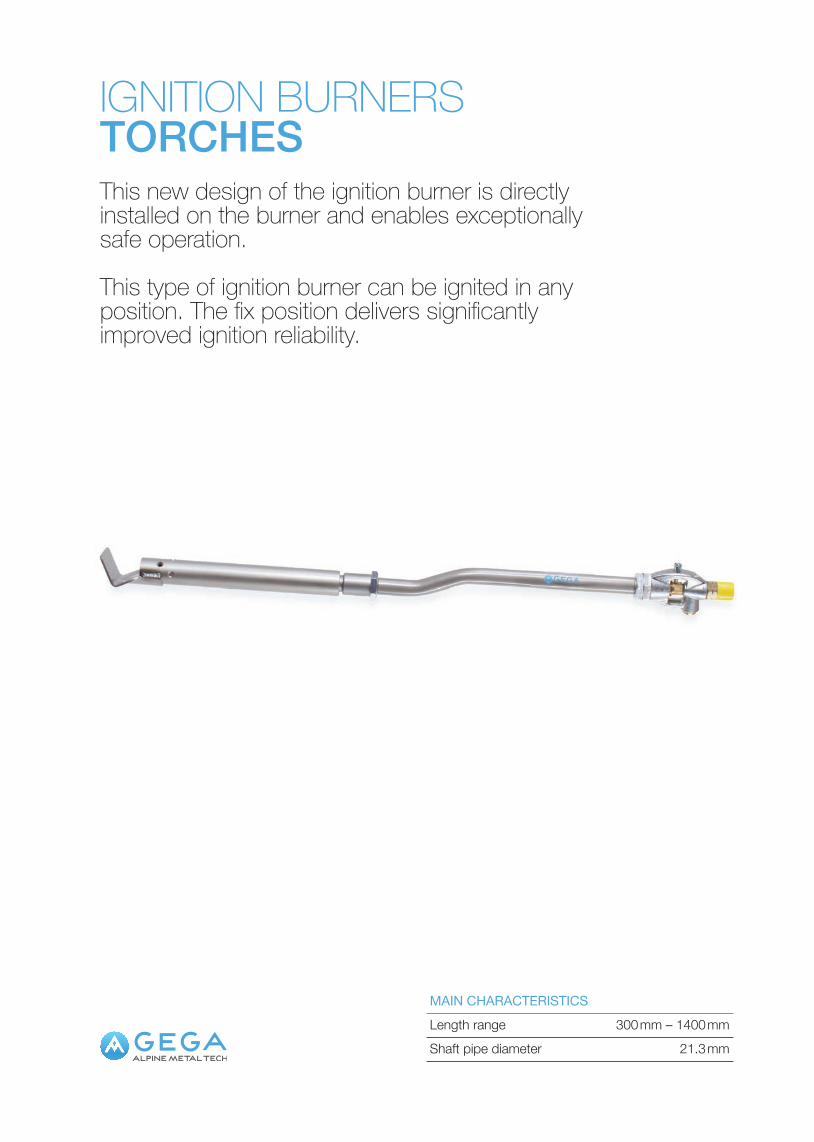
IGNITION BURNERSTORCHESThis new design of the ignition burner is directly installed on the burner and enables exceptionally safe operation.
This type of ignition burner can be ignited in any position. The fix position delivers significantly improved ignition reliability.
Length range 300 mm – 1400 mmMAIN CHARACTERISTICS
Shaft pipe diameter 21.3 mm
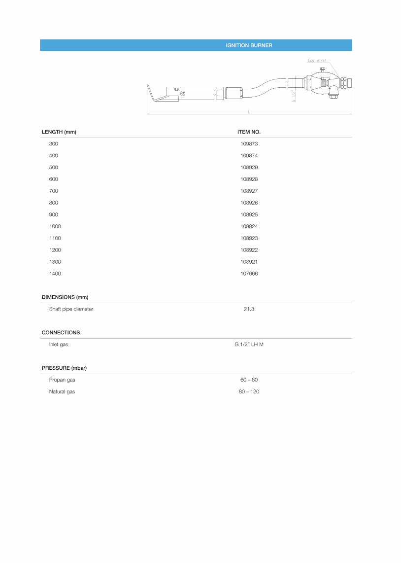
IGNITION BURNER
LENGTH (mm) ITEM NO.
300 109873
400 109874
500 108929
600 108928
700 108927
800 108926
900 108925
1000 108924
1100 108923
1200 108922
1300 108921
1400 107666
DIMENSIONS (mm)
Shaft pipe diameter 21.3
CONNECTIONS
Inlet gas G 1/2″ LH M
PRESSURE (mbar)
Propan gas 60 – 80
Natural gas 80 – 120
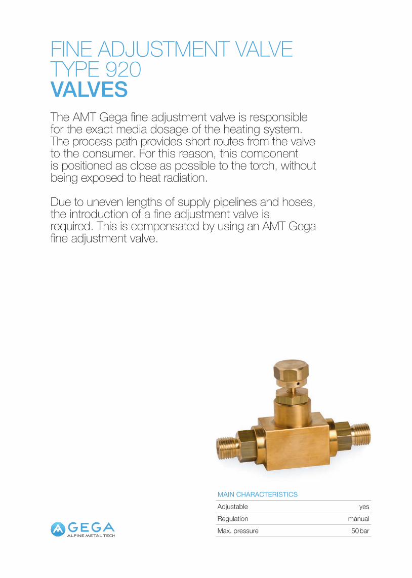
FINE ADJUSTMENT VALVETYPE 920VALVESThe AMT Gega fine adjustment valve is responsible for the exact media dosage of the heating system. The process path provides short routes from the valve to the consumer. For this reason, this component is positioned as close as possible to the torch, without being exposed to heat radiation.
Due to uneven lengths of supply pipelines and hoses, the introduction of a fine adjustment valve is required. This is compensated by using an AMT Gega fine adjustment valve.
Regulation manual
MAIN CHARACTERISTICS
Max. pressure 50 bar
Adjustable yes
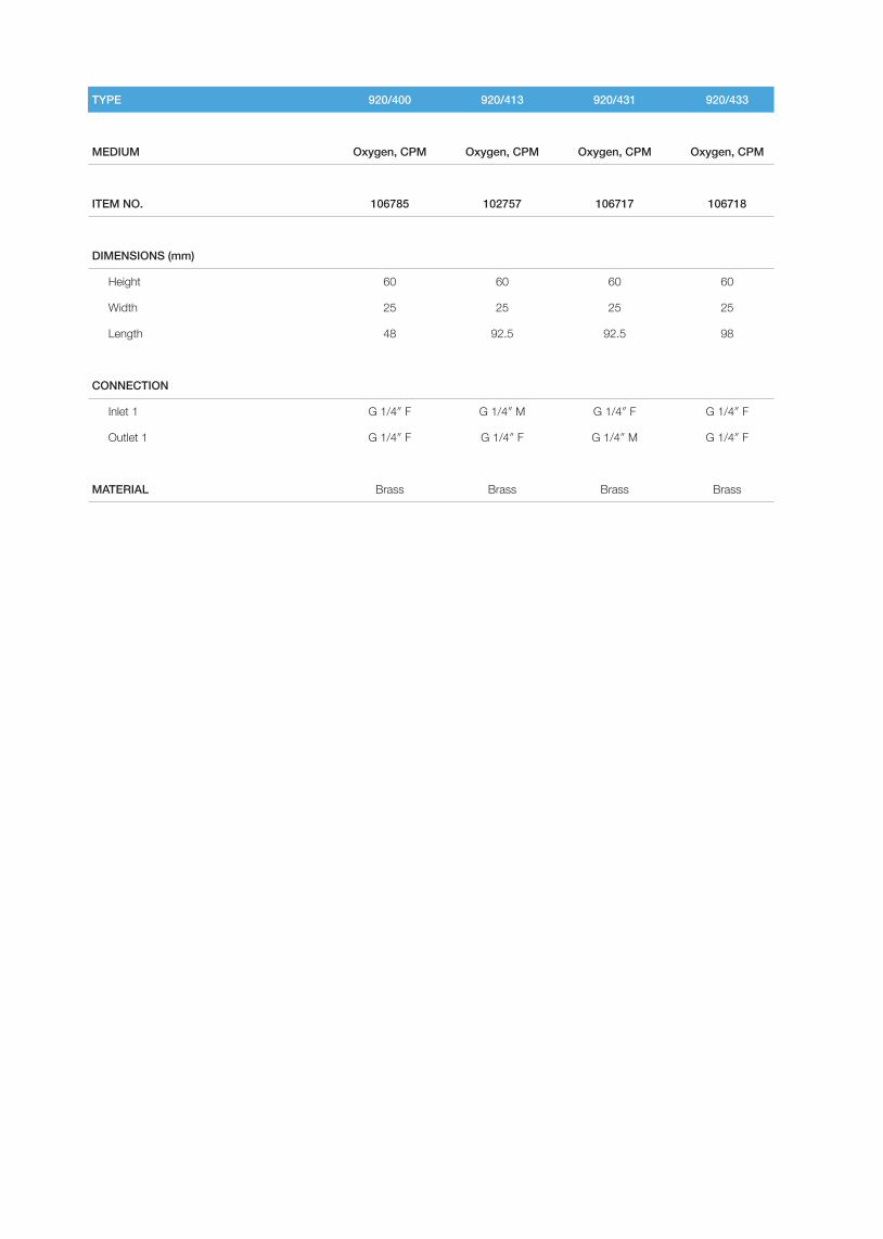
TYPE 920/400 920/413 920/431 920/433
MEDIUM Oxygen, CPM Oxygen, CPM Oxygen, CPM Oxygen, CPM
ITEM NO. 106785 102757 106717 106718
DIMENSIONS (mm)
Height 60 60 60 60
Width 25 25 25 25
Length 48 92.5 92.5 98
CONNECTION
Inlet 1 G 1/4″ F G 1/4″ M G 1/4″ F G 1/4″ F
Outlet 1 G 1/4″ F G 1/4″ F G 1/4″ M G 1/4″ F
MATERIAL Brass Brass Brass Brass
VALVESFine adjustment valve / Type 920Gas flow controller / Type 8802/2 way valve / Type 9552/2 way valve / Type 966
VALVES
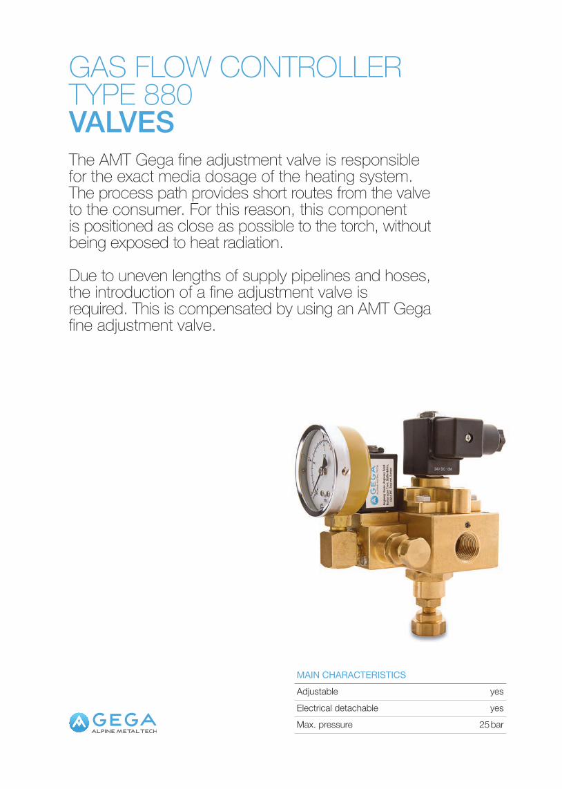
Electrical detachable yes
MAIN CHARACTERISTICS
Max. pressure 25 bar
Adjustable yes
GAS FLOW CONTROLLERTYPE 880VALVESThe AMT Gega fine adjustment valve is responsible for the exact media dosage of the heating system. The process path provides short routes from the valve to the consumer. For this reason, this component is positioned as close as possible to the torch, without being exposed to heat radiation.
Due to uneven lengths of supply pipelines and hoses, the introduction of a fine adjustment valve is required. This is compensated by using an AMT Gega fine adjustment valve.
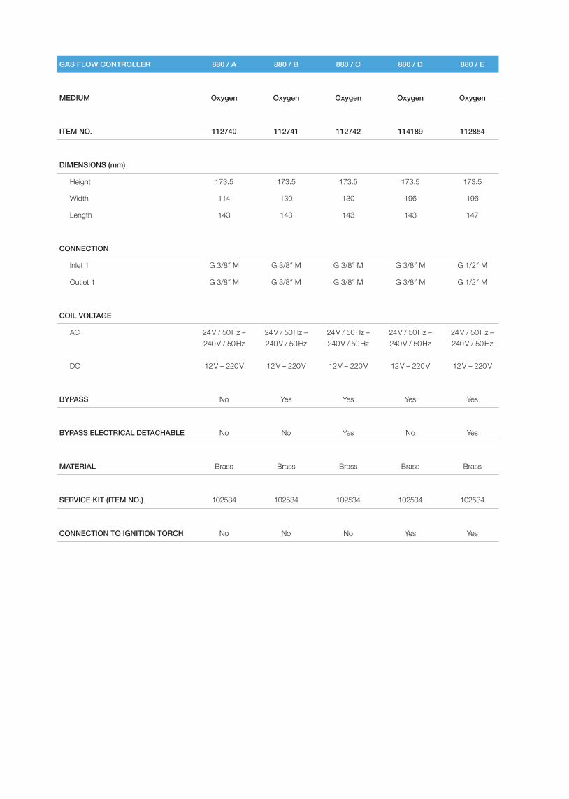
GAS FLOW CONTROLLER 880 / A 880 / B 880 / C 880 / D 880 / E
MEDIUM Oxygen Oxygen Oxygen Oxygen Oxygen
ITEM NO. 112740 112741 112742 114189 112854
DIMENSIONS (mm)
Height 173.5 173.5 173.5 173.5 173.5
Width 114 130 130 196 196
Length 143 143 143 143 147
CONNECTION
Inlet 1 G 3/8″ M G 3/8″ M G 3/8″ M G 3/8″ M G 1/2″ M
Outlet 1 G 3/8″ M G 3/8″ M G 3/8″ M G 3/8″ M G 1/2″ M
COIL VOLTAGE
AC 24 V / 50 Hz – 240 V / 50 Hz
24 V / 50 Hz – 240 V / 50 Hz
24 V / 50 Hz – 240 V / 50 Hz
24 V / 50 Hz – 240 V / 50 Hz
24 V / 50 Hz – 240 V / 50 Hz
DC 12 V – 220 V 12 V – 220 V 12 V – 220 V 12 V – 220 V 12 V – 220 V
BYPASS No Yes Yes Yes Yes
BYPASS ELECTRICAL DETACHABLE No No Yes No Yes
MATERIAL Brass Brass Brass Brass Brass
SERVICE KIT (ITEM NO.) 102534 102534 102534 102534 102534
CONNECTION TO IGNITION TORCH No No No Yes Yes
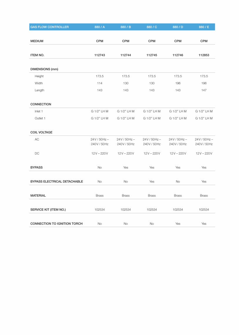
GAS FLOW CONTROLLER 880 / A 880 / B 880 / C 880 / D 880 / E
MEDIUM CPM CPM CPM CPM CPM
ITEM NO. 112743 112744 112745 112746 112853
DIMENSIONS (mm)
Height 173.5 173.5 173.5 173.5 173.5
Width 114 130 130 196 196
Length 143 143 143 143 147
CONNECTION
Inlet 1 G 1/2″ LH M G 1/2″ LH M G 1/2″ LH M G 1/2″ LH M G 1/2″ LH M
Outlet 1 G 1/2″ LH M G 1/2″ LH M G 1/2″ LH M G 1/2″ LH M G 1/2″ LH M
COIL VOLTAGE
AC 24 V / 50 Hz – 240 V / 50 Hz
24 V / 50 Hz – 240 V / 50 Hz
24 V / 50 Hz – 240 V / 50 Hz
24 V / 50 Hz – 240 V / 50 Hz
24 V / 50 Hz – 240 V / 50 Hz
DC 12 V – 220 V 12 V – 220 V 12 V – 220 V 12 V – 220 V 12 V – 220 V
BYPASS No Yes Yes Yes Yes
BYPASS ELECTRICAL DETACHABLE No No Yes No Yes
MATERIAL Brass Brass Brass Brass Brass
SERVICE KIT (ITEM NO.) 102534 102534 102534 102534 102534
CONNECTION TO IGNITION TORCH No No No Yes Yes
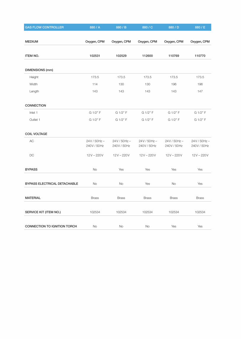
GAS FLOW CONTROLLER 880 / A 880 / B 880 / C 880 / D 880 / E
MEDIUM Oxygen, CPM Oxygen, CPM Oxygen, CPM Oxygen, CPM Oxygen, CPM
ITEM NO. 102531 102529 112600 110769 110770
DIMENSIONS (mm)
Height 173.5 173.5 173.5 173.5 173.5
Width 114 130 130 196 196
Length 143 143 143 143 147
CONNECTION
Inlet 1 G 1/2″ F G 1/2″ F G 1/2″ F G 1/2″ F G 1/2″ F
Outlet 1 G 1/2″ F G 1/2″ F G 1/2″ F G 1/2″ F G 1/2″ F
COIL VOLTAGE
AC 24 V / 50 Hz – 240 V / 50 Hz
24 V / 50 Hz – 240 V / 50 Hz
24 V / 50 Hz – 240 V / 50 Hz
24 V / 50 Hz – 240 V / 50 Hz
24 V / 50 Hz – 240 V / 50 Hz
DC 12 V – 220 V 12 V – 220 V 12 V – 220 V 12 V – 220 V 12 V – 220 V
BYPASS No Yes Yes Yes Yes
BYPASS ELECTRICAL DETACHABLE No No Yes No Yes
MATERIAL Brass Brass Brass Brass Brass
SERVICE KIT (ITEM NO.) 102534 102534 102534 102534 102534
CONNECTION TO IGNITION TORCH No No No Yes Yes
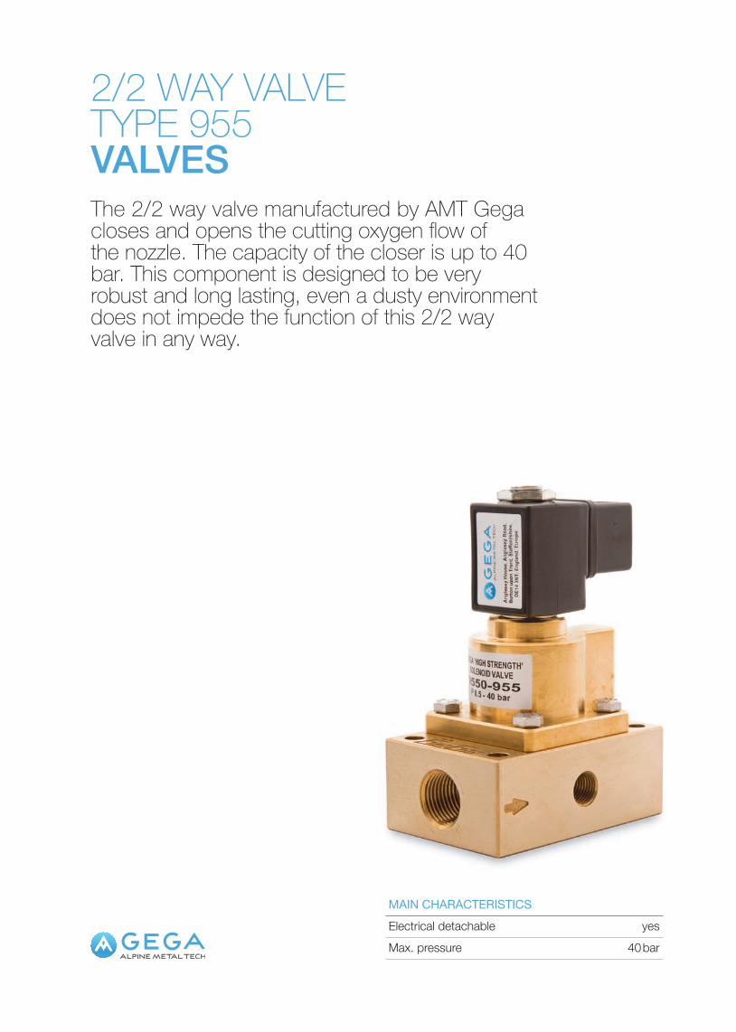
2/2 WAY VALVE TYPE 955VALVESThe 2/2 way valve manufactured by AMT Gega closes and opens the cutting oxygen flow of the nozzle. The capacity of the closer is up to 40 bar. This component is designed to be very robust and long lasting, even a dusty environment does not impede the function of this 2/2 way valve in any way.
Electrical detachable yesMAIN CHARACTERISTICS
Max. pressure 40 bar
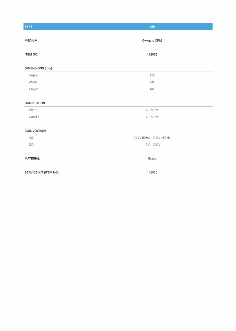
TYPE 955
MEDIUM Oxygen, CPM
ITEM NO. 112828
DIMENSIONS (mm)
Height 112
Width 60
Length 147
CONNECTION
Inlet 1 G 1/2″ M
Outlet 1 G 1/2″ M
COIL VOLTAGE
AC 24 V / 50 Hz – 240 V / 50 Hz
DC 12 V – 220 V
MATERIAL Brass
SERVICE KIT (ITEM NO.) 112655
Electrical detachable yesMAIN CHARACTERISTICS
Max. pressure 25 bar
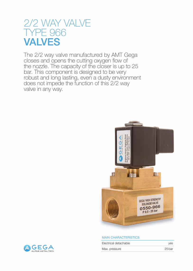
2/2 WAY VALVETYPE 966VALVESThe 2/2 way valve manufactured by AMT Gega closes and opens the cutting oxygen flow of the nozzle. The capacity of the closer is up to 25 bar. This component is designed to be very robust and long lasting, even a dusty environment does not impede the function of this 2/2 way valve in any way.
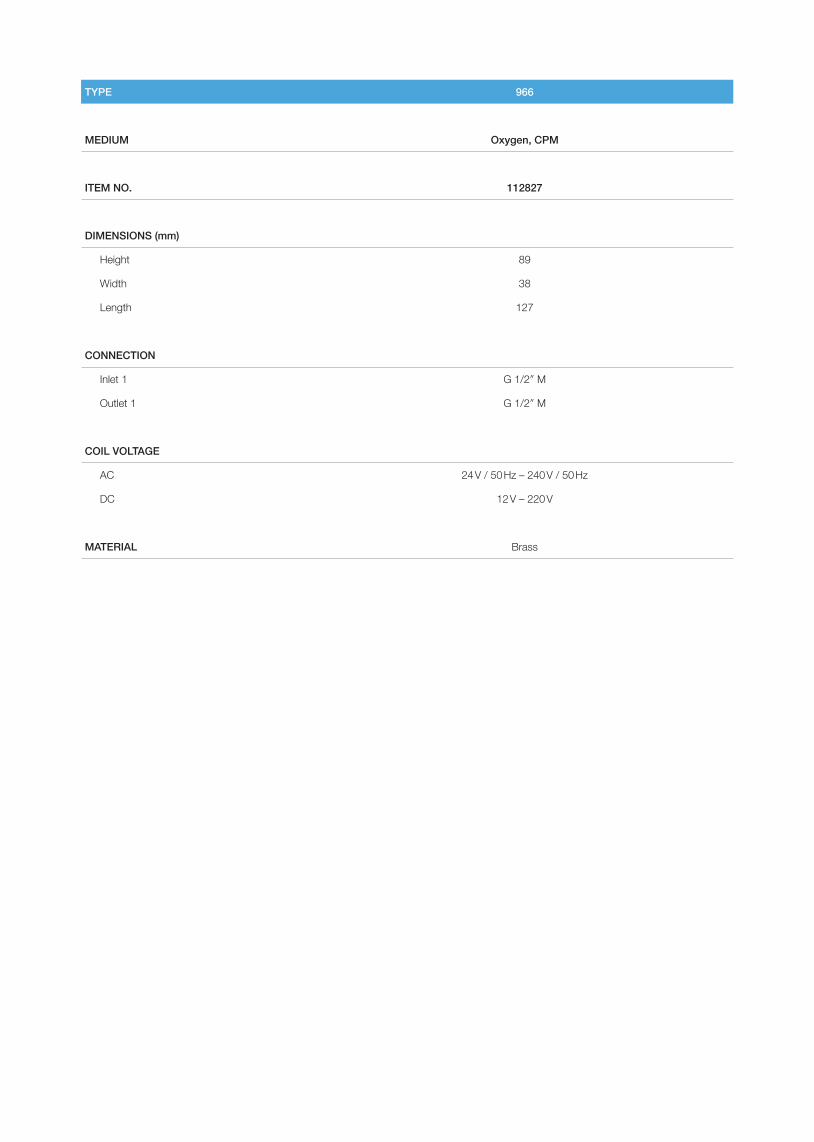
TYPE 966
MEDIUM Oxygen, CPM
ITEM NO. 112827
DIMENSIONS (mm)
Height 89
Width 38
Length 127
CONNECTION
Inlet 1 G 1/2″ M
Outlet 1 G 1/2″ M
COIL VOLTAGE
AC 24 V / 50 Hz – 240 V / 50 Hz
DC 12 V – 220 V
MATERIAL Brass
REGULATORSGS rangeGL rangeKuppel valvesGK regulators
REGULATO
RS
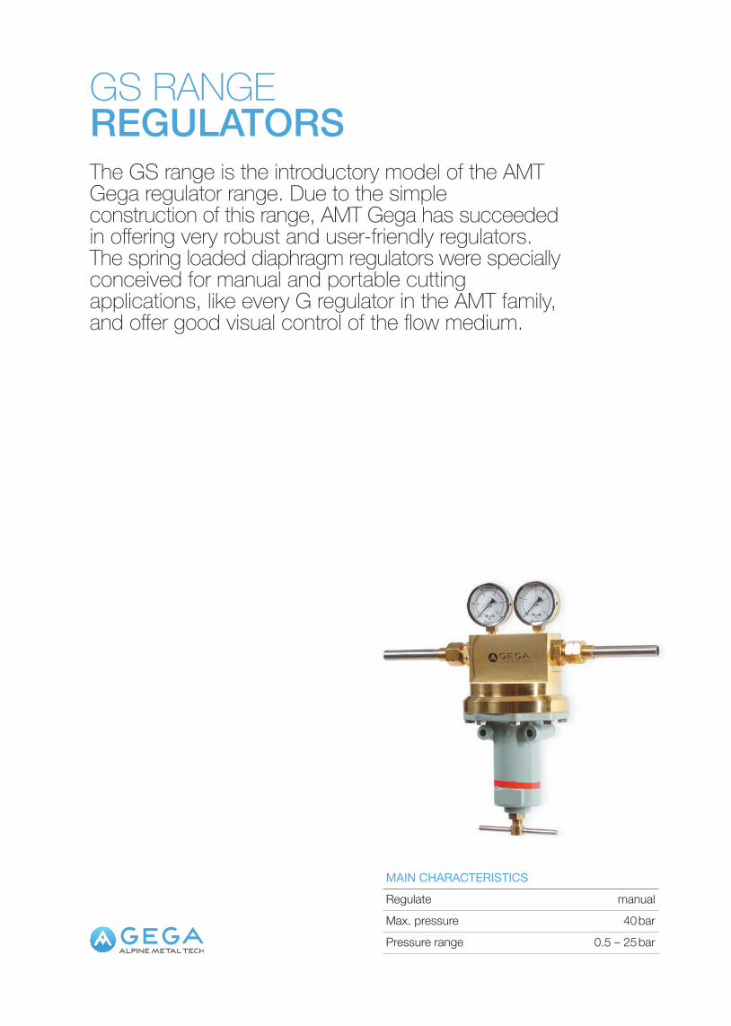
GS RANGEREGULATORSThe GS range is the introductory model of the AMT Gega regulator range. Due to the simple construction of this range, AMT Gega has succeeded in offering very robust and user-friendly regulators. The spring loaded diaphragm regulators were specially conceived for manual and portable cutting applications, like every G regulator in the AMT family, and offer good visual control of the flow medium.
Max. pressure 40 barRegulate manualMAIN CHARACTERISTICS
Pressure range 0.5 – 25 bar
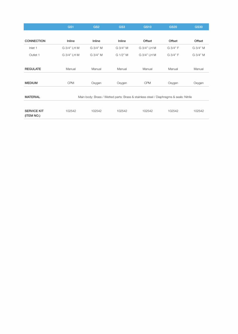
GS1 GS2 GS3 GS10 GS20 GS30
CONNECTION Inline Inline Inline Offset Offset Offset
Inlet 1 G 3/4″ LH M G 3/4″ M G 3/4″ M G 3/4″ LH M G 3/4″ F G 3/4″ M
Outlet 1 G 3/4″ LH M G 3/4″ M G 1/2″ M G 3/4″ LH M G 3/4″ F G 3/4″ M
REGULATE Manual Manual Manual Manual Manual Manual
MEDIUM CPM Oxygen Oxygen CPM Oxygen Oxygen
MATERIAL
SERVICE KIT (ITEM NO.)
102542 102542 102542 102542 102542 102542
Main body: Brass / Wetted parts: Brass & stainless steel / Diaphragms & seals: Nitrile
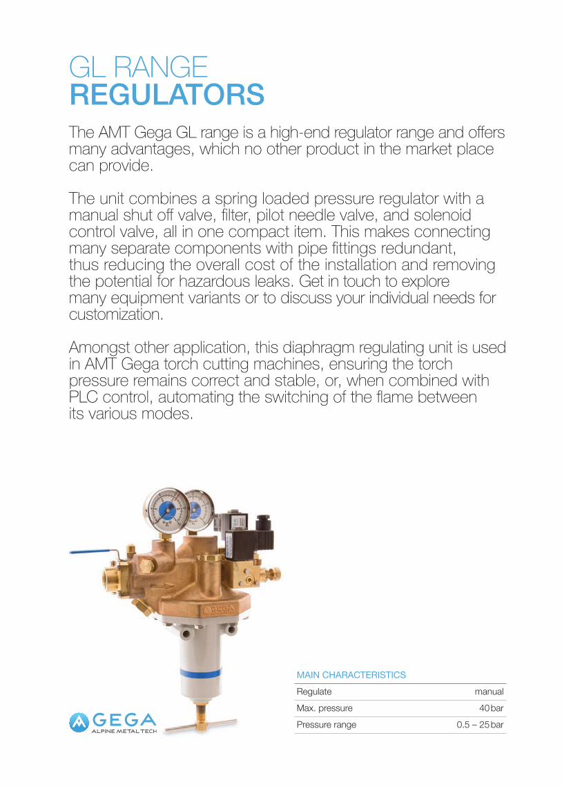
GL RANGEREGULATORSThe AMT Gega GL range is a high-end regulator range and offers many advantages, which no other product in the market place can provide.
The unit combines a spring loaded pressure regulator with a manual shut off valve, filter, pilot needle valve, and solenoid control valve, all in one compact item. This makes connecting many separate components with pipe fittings redundant, thus reducing the overall cost of the installation and removing the potential for hazardous leaks. Get in touch to explore many equipment variants or to discuss your individual needs for customization.
Amongst other application, this diaphragm regulating unit is used in AMT Gega torch cutting machines, ensuring the torch pressure remains correct and stable, or, when combined with PLC control, automating the switching of the flame between its various modes.
Max. pressure 40 barRegulate manualMAIN CHARACTERISTICS
Pressure range 0.5 – 25 bar
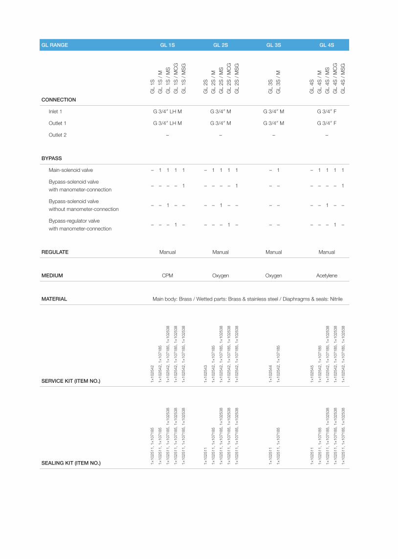
GL RANGE GL 1S GL 2S GL 3S GL 4S
CONNECTION
Inlet 1 G 3/4″ LH M G 3/4″ M G 3/4″ M G 3/4″ F
Outlet 1 G 3/4″ LH M G 3/4″ M G 3/4″ M G 3/4″ F
Outlet 2 – – – –
BYPASS
Main-solenoid valve
Bypass-solenoid valve with manometer-connection
Bypass-solenoid valve without manometer-connection
Bypass-regulator valve with manometer-connection
REGULATE Manual Manual Manual Manual
MEDIUM CPM Oxygen Oxygen Acetylene
MATERIAL
SERVICE KIT (ITEM NO.)
SEALING KIT (ITEM NO.)
GL
1SG
L 1S
/ M
GL
1S /
MS
GL
1S /
MCG
GL
1S /
MSG
1×10
2542
1×10
2542
, 1×1
0718
5
1×10
2542
, 1×1
0718
5, 1×1
0253
8
1×10
2542
, 1×1
0718
5, 1×1
0253
8
1×10
2542
, 1×1
0718
5, 1×1
0253
8
1×10
2543
1×10
2542
, 1×1
0718
5
1×10
2542
, 1×1
0718
5, 1×1
0253
8
1×10
2542
, 1×1
0718
5, 1×1
0253
8
1×10
2542
, 1×1
0718
5, 1×1
0253
8
1×10
2544
1×10
2542
, 1×1
0718
5
1×10
2545
1×10
2542
, 1×1
0718
5
1×10
2542
, 1×1
0718
5, 1×1
0253
8
1×10
2542
, 1×1
0718
5, 1×1
0253
8
1×10
2542
, 1×1
0718
5, 1×1
0253
8
1×10
2511
, 1×1
0718
5
1×10
2511
, 1×1
0718
5
1×10
2511
, 1×1
0718
5, 1×1
0253
8
1×10
2511
, 1×1
0718
5, 1×1
0253
8
1×10
2511
, 1×1
0718
5, 1×1
0253
8
1×10
2511
1×10
2511
, 1×1
0718
5
1×10
2511
, 1×1
0718
5, 1×1
0253
8
1×10
2511
, 1×1
0718
5, 1×1
0253
8
1×10
2511
, 1×1
0718
5, 1×1
0253
8
1×10
2511
1×10
2511
, 1×1
0718
5
1×10
2511
1×10
2511
, 1×1
0718
5
1×10
2511
, 1×1
0718
5, 1×1
0253
8
1×10
2511
, 1×1
0718
5, 1×1
0253
8
1×10
2511
, 1×1
0718
5, 1×1
0253
8
GL
2SG
L 2S
/ M
GL
2S /
MS
GL
2S /
MCG
GL
2S /
MSG
GL
3SG
L 3S
/ M
GL
4SG
L 4S
/ M
GL
4S /
MS
GL
4S /
MCG
GL
4S /
MSG
–
–
–
–
1
–
1
–
1
–
–
–
1
–
–
1
1
1
–
–
–
–
–
–
1
–
1
–
1
–
–
–
1
–
–
1
1
1
–
–
–
–
–
–
1
–
–
–
–
–
–
–
1
–
1
–
1
–
–
–
1
–
–
1
1
1
–
–
Main body: Brass / Wetted parts: Brass & stainless steel / Diaphragms & seals: Nitrile
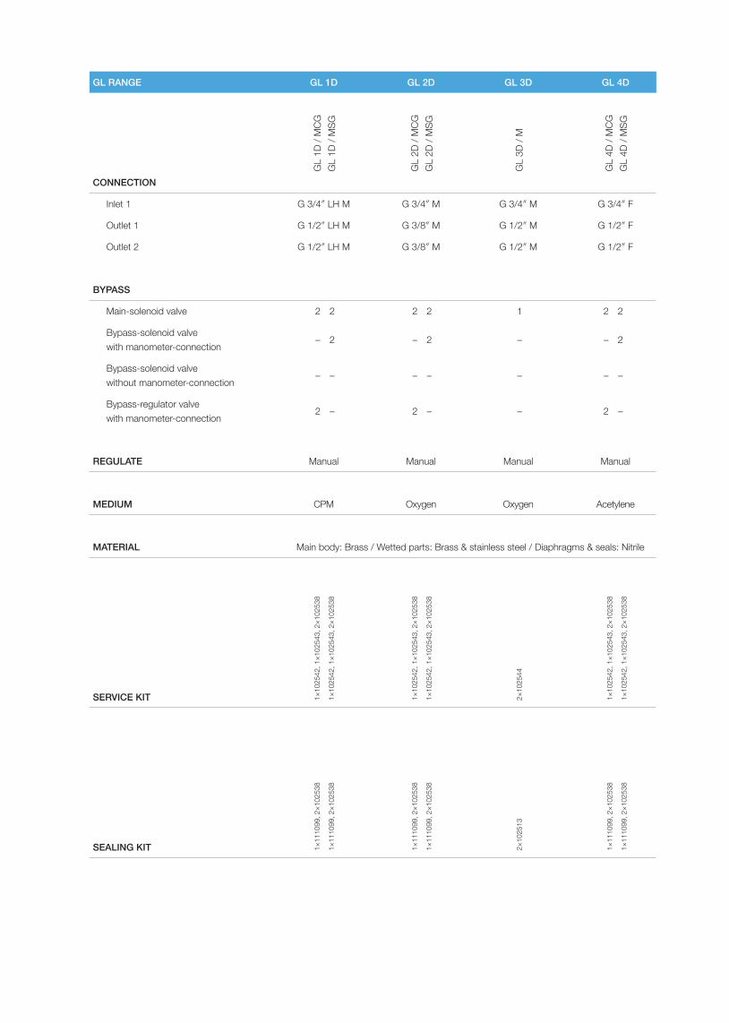
GL RANGE GL 1D GL 2D GL 3D GL 4D
CONNECTION
Inlet 1 G 3/4″ LH M G 3/4″ M G 3/4″ M G 3/4″ F
Outlet 1 G 1/2″ LH M G 3/8″ M G 1/2″ M G 1/2″ F
Outlet 2 G 1/2″ LH M G 3/8″ M G 1/2″ M G 1/2″ F
BYPASS
Main-solenoid valve
Bypass-solenoid valve with manometer-connection
Bypass-solenoid valve without manometer-connection
Bypass-regulator valve with manometer-connection
REGULATE Manual Manual Manual Manual
MEDIUM CPM Oxygen Oxygen Acetylene
MATERIAL
SERVICE KIT
SEALING KIT
GL
1D /
MCG
GL
1D /
MSG
1×10
2542
, 1×1
0254
3, 2×1
0253
8
1×10
2542
, 1×1
0254
3, 2×1
0253
8
1×10
2542
, 1×1
0254
3, 2×1
0253
8
1×10
2542
, 1×1
0254
3, 2×1
0253
8
2×10
2544
1×10
2542
, 1×1
0254
3, 2×1
0253
8
1×10
2542
, 1×1
0254
3, 2×1
0253
8
1×11
1099
, 2×1
0253
8
1×11
1099
, 2×1
0253
8
1×11
1099
, 2×1
0253
8
1×11
1099
, 2×1
0253
8
2×10
2513
1×11
1099
, 2×1
0253
8
1×11
1099
, 2×1
0253
8
GL
2D /
MCG
GL
2D /
MSG
GL
3D /
M
GL
4D /
MCG
GL
4D /
MSG
2
–
–
2
2
2
–
–
2
–
–
2
2
2
–
–
2
–
–
2
2
2
–
–
1
–
–
–
Main body: Brass / Wetted parts: Brass & stainless steel / Diaphragms & seals: Nitrile

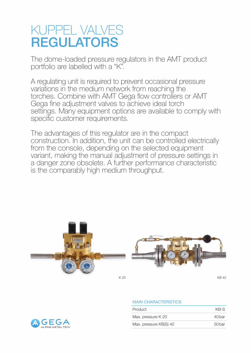
KUPPEL VALVESREGULATORSThe dome-loaded pressure regulators in the AMT product portfolio are labelled with a “K”.
A regulating unit is required to prevent occasional pressure variations in the medium network from reaching the torches. Combine with AMT Gega flow controllers or AMT Gega fine adjustment valves to achieve ideal torch settings. Many equipment options are available to comply with specific customer requirements.
The advantages of this regulator are in the compact construction. In addition, the unit can be controlled electrically from the console, depending on the selected equipment variant, making the manual adjustment of pressure settings in a danger zone obsolete. A further performance characteristic is the comparably high medium throughput.
Max. pressure KB(S) 42 50 barMax. pressure K 20 40 barProduct KB-SMAIN CHARACTERISTICS
KB 42K 20
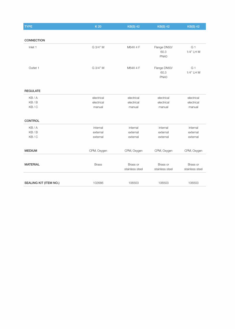
TYPE K 20 KB(S) 42 KB(S) 42 KB(S) 42
CONNECTION
Inlet 1 G 3/4″ M M64X 4 F Flange DN50/60.3PN40
G 1 1/4″ LH M
Outlet 1 G 3/4″ M M64X 4 F Flange DN50/60.3PN40
G 1 1/4″ LH M
REGULATE
KB / AKB / BKB / C
electricalelectricalmanual
electricalelectricalmanual
electricalelectricalmanual
electricalelectricalmanual
CONTROL
KB / AKB / BKB / C
internalexternalexternal
internalexternalexternal
internalexternalexternal
internalexternalexternal
MEDIUM CPM, Oxygen CPM, Oxygen CPM, Oxygen CPM, Oxygen
MATERIAL Brass Brass or stainless steel
Brass or stainless steel
Brass or stainless steel
SEALING KIT (ITEM NO.) 102686 106503 106503 106503
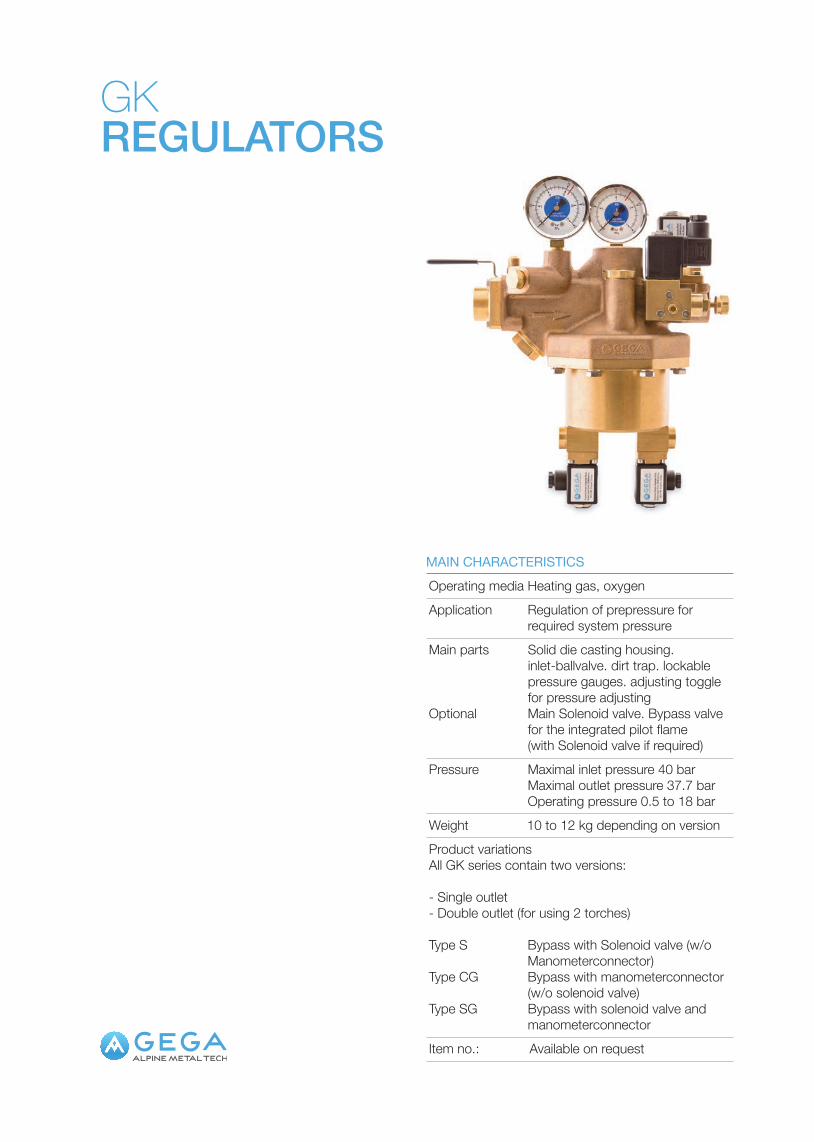
GKREGULATORS
Weight 10 to 12 kg depending on version
Pressure Maximal inlet pressure 40 bar Maximal outlet pressure 37.7 bar Operating pressure 0.5 to 18 bar
Operating media Heating gas, oxygenMAIN CHARACTERISTICS
Product variations All GK series contain two versions:
- Single outlet- Double outlet (for using 2 torches)
Type S Bypass with Solenoid valve (w/o Manometerconnector)
Type CG Bypass with manometerconnector (w/o solenoid valve)
Type SG Bypass with solenoid valve and manometerconnector
Item no.: Available on request
Application Regulation of prepressure for required system pressure
Main parts Solid die casting housing. inlet-ballvalve. dirt trap. lockable pressure gauges. adjusting toggle for pressure adjusting
Optional Main Solenoid valve. Bypass valve for the integrated pilot flame (with Solenoid valve if required)


SCARFERMachine scarfer– MHD 300– HD SW 27/10– MH 310– MBR 36
Hand scarfer– MST 1500 / CGA– SHF-100 F 1500
SCARFER
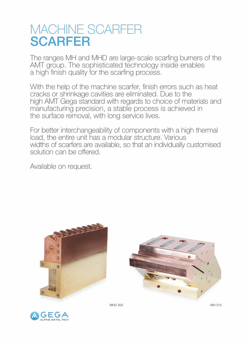
MACHINE SCARFERSCARFERThe ranges MH and MHD are large-scale scarfing burners of the AMT group. The sophisticated technology inside enables a high finish quality for the scarfing process.
With the help of the machine scarfer, finish errors such as heat cracks or shrinkage cavities are eliminated. Due to the high AMT Gega standard with regards to choice of materials and manufacturing precision, a stable process is achieved in the surface removal, with long service lives.
For better interchangeability of components with a high thermal load, the entire unit has a modular structure. Various widths of scarfers are available, so that an individually customised solution can be offered.
Available on request.
MH 310MHD 300

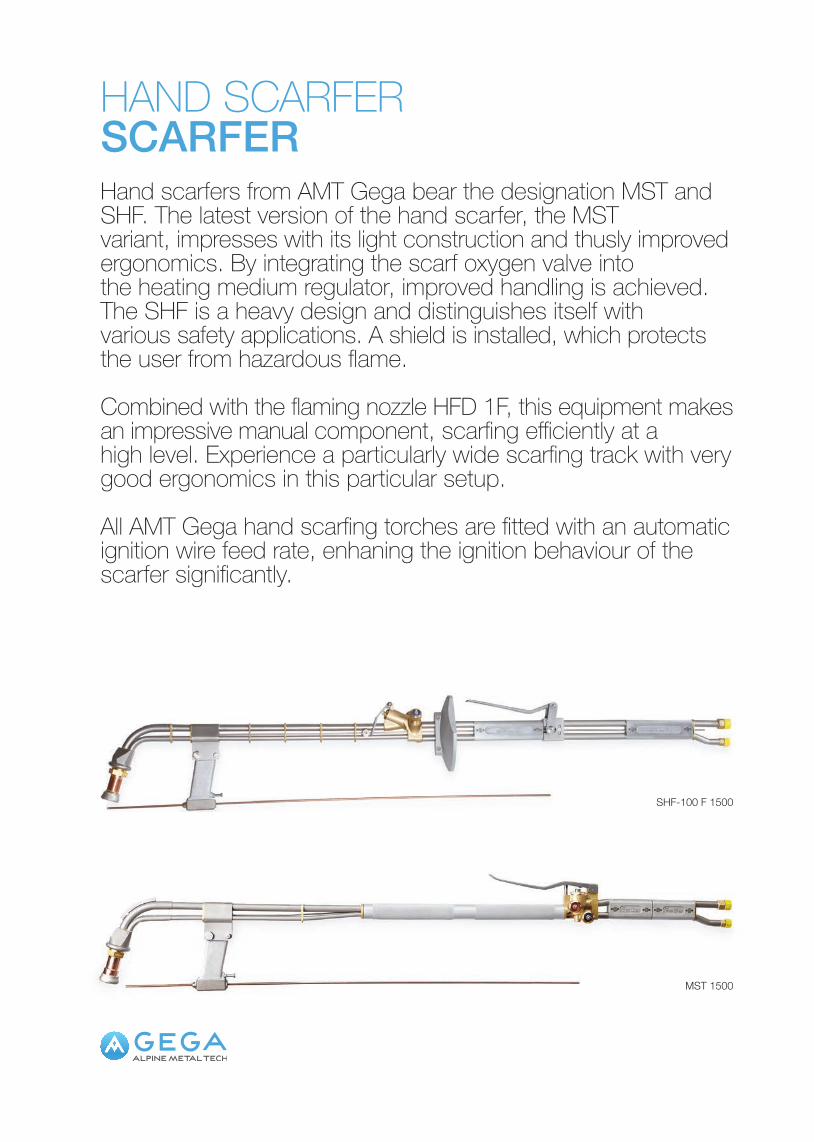
SHF-100 F 1500
MST 1500
HAND SCARFERSCARFERHand scarfers from AMT Gega bear the designation MST and SHF. The latest version of the hand scarfer, the MST variant, impresses with its light construction and thusly improved ergonomics. By integrating the scarf oxygen valve into the heating medium regulator, improved handling is achieved.The SHF is a heavy design and distinguishes itself with various safety applications. A shield is installed, which protects the user from hazardous flame.
Combined with the flaming nozzle HFD 1F, this equipment makes an impressive manual component, scarfing efficiently at a high level. Experience a particularly wide scarfing track with very good ergonomics in this particular setup.
All AMT Gega hand scarfing torches are fitted with an automatic ignition wire feed rate, enhaning the ignition behaviour of the scarfer significantly.
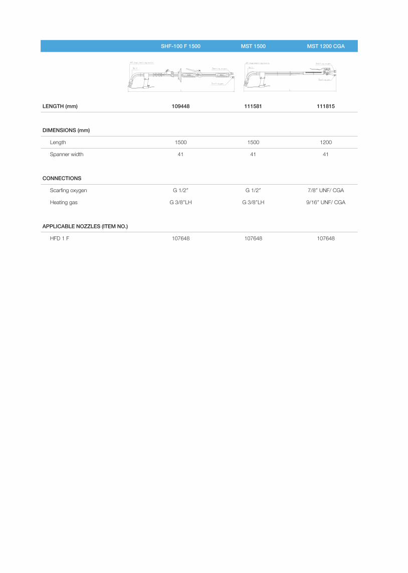
SHF-100 F 1500 MST 1500 MST 1200 CGA
LENGTH (mm) 109448 111581 111815
DIMENSIONS (mm)
Length 1500 1500 1200
Spanner width 41 41 41
CONNECTIONS
Scarfing oxygen G 1/2″ G 1/2″ 7/8″ UNF/ CGA
Heating gas G 3/8″LH G 3/8″LH 9/16″ UNF/ CGA
APPLICABLE NOZZLES (ITEM NO.)
HFD 1 F 107648 107648 107648
SAFETY EQUIPMENTSafety devices– LG/GRM– LG/GRM D / LG/GRM D R1.0– SIMAX 5 / SIMAX 8– SIMAX LG VII– SIMAX 4NH– DEMAX 5
Non-return devices– LG/GRM– LG/GRM/S– GRV2-20
SAFETYEQ
UIPMENT
SAFETY DEVICESSAFETY EQUIPMENTAll AMT Gega burners are provided with safety elements to ensure safe, frictionless operation. When dealing with explosive gas and oxygen mixtures, safety devices must be used to avoid flashbacks. They exhibit exceptional, “Made in Germany” build quality and fulfil the required DIN EN 746-2 standards.
These safety devices are specially optimised for autogenous use, offering maximum protection for machine components.

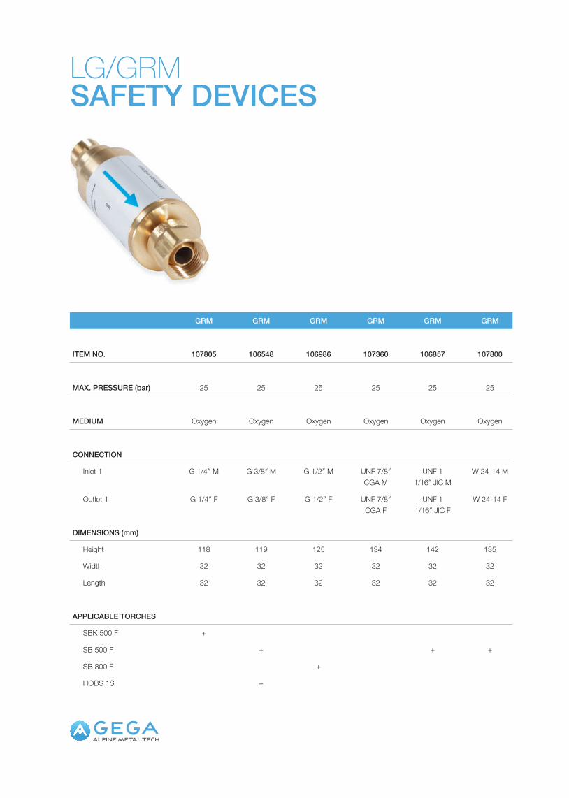
LG/GRMSAFETY DEVICES
GRM GRM GRM GRM GRM GRM
ITEM NO. 107805 106548 106986 107360 106857 107800
MAX. PRESSURE (bar) 25 25 25 25 25 25
MEDIUM Oxygen Oxygen Oxygen Oxygen Oxygen Oxygen
CONNECTION
Inlet 1 G 1/4″ M G 3/8″ M G 1/2″ M UNF 7/8″ CGA M
UNF 1 1/16″ JIC M
W 24-14 M
Outlet 1 G 1/4″ F G 3/8″ F G 1/2″ F UNF 7/8″ CGA F
UNF 1 1/16″ JIC F
W 24-14 F
DIMENSIONS (mm)
Height 118 119 125 134 142 135
Width 32 32 32 32 32 32
Length 32 32 32 32 32 32
APPLICABLE TORCHES
SBK 500 F +
SB 500 F + + +
SB 800 F +
HOBS 1S +

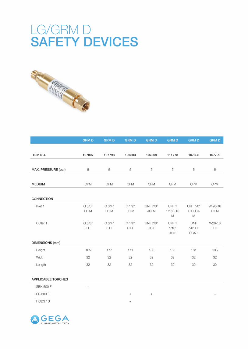
LG/GRM DSAFETY DEVICES
GRM D GRM D GRM D GRM D GRM D GRM D GRM D
ITEM NO. 107807 107798 107803 107809 111773 107808 107799
MAX. PRESSURE (bar) 5 5 5 5 5 5 5
MEDIUM CPM CPM CPM CPM CPM CPM CPM
CONNECTION
Inlet 1 G 3/8″ LH M
G 3/4″ LH M
G 1/2″ LH M
UNF 7/8″ JIC M
UNF 1 1/16″ JIC
M
UNF 7/8″ LH CGA
M
W 28-18 LH M
Outlet 1 G 3/8″ LH F
G 3/4″ LH F
G 1/2″ LH F
UNF 7/8″ JIC F
UNF 1 1/16″ JIC F
UNF 7/8″ LH CGA F
W28-18 LH F
DIMENSIONS (mm)
Height 165 177 171 186 185 181 135
Width 32 32 32 32 32 32 32
Length 32 32 32 32 32 32 32
APPLICABLE TORCHES
SBK 500 F +
SB 500 F + + +
HOBS 1S +

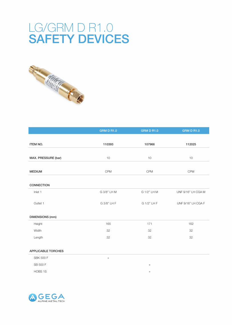
LG/GRM D R1.0SAFETY DEVICES
GRM D R1.0 GRM D R1.0 GRM D R1.0
ITEM NO. 110393 107966 112025
MAX. PRESSURE (bar) 10 10 10
MEDIUM CPM CPM CPM
CONNECTION
Inlet 1 G 3/8″ LH M G 1/2″ LH M UNF 9/16″ LH CGA M
Outlet 1 G 3/8″ LH F G 1/2″ LH F UNF 9/16″ LH CGA F
DIMENSIONS (mm)
Height 165 171 162
Width 32 32 32
Length 32 32 32
APPLICABLE TORCHES
SBK 500 F +
SB 500 F +
HOBS 1S +

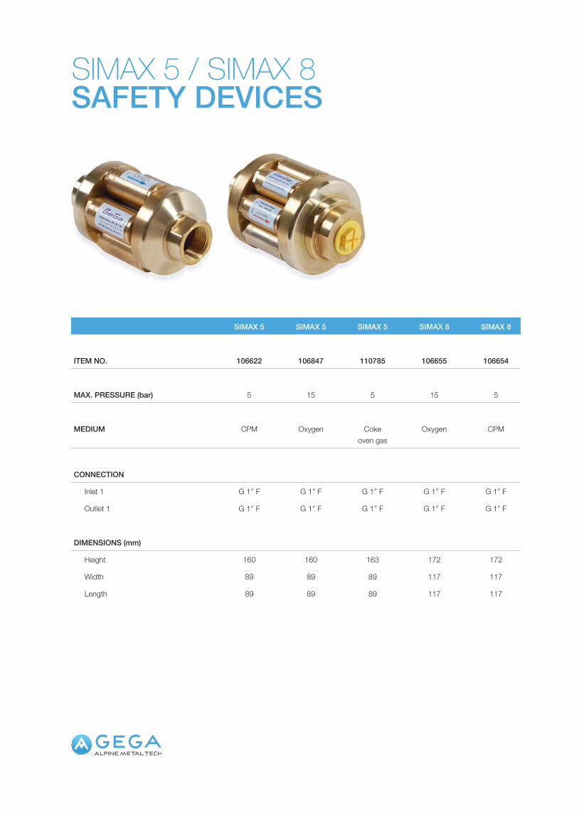
SIMAX 5 / SIMAX 8SAFETY DEVICES
SIMAX 5 SIMAX 5 SIMAX 5 SIMAX 8 SIMAX 8
ITEM NO. 106622 106847 110785 106655 106654
MAX. PRESSURE (bar) 5 15 5 15 5
MEDIUM CPM Oxygen Coke oven gas
Oxygen CPM
CONNECTION
Inlet 1 G 1″ F G 1″ F G 1″ F G 1″ F G 1″ F
Outlet 1 G 1″ F G 1″ F G 1″ F G 1″ F G 1″ F
DIMENSIONS (mm)
Height 160 160 163 172 172
Width 89 89 89 117 117
Length 89 89 89 117 117

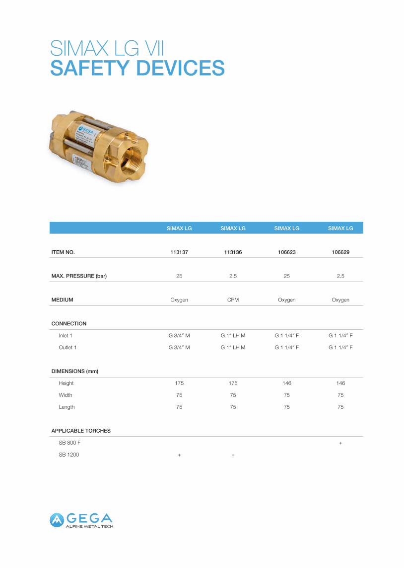
SIMAX LG VIISAFETY DEVICES
SIMAX LG SIMAX LG SIMAX LG SIMAX LG
ITEM NO. 113137 113136 106623 106629
MAX. PRESSURE (bar) 25 2.5 25 2.5
MEDIUM Oxygen CPM Oxygen Oxygen
CONNECTION
Inlet 1 G 3/4″ M G 1″ LH M G 1 1/4″ F G 1 1/4″ F
Outlet 1 G 3/4″ M G 1″ LH M G 1 1/4″ F G 1 1/4″ F
DIMENSIONS (mm)
Height 175 175 146 146
Width 75 75 75 75
Length 75 75 75 75
APPLICABLE TORCHES
SB 800 F +
SB 1200 + +

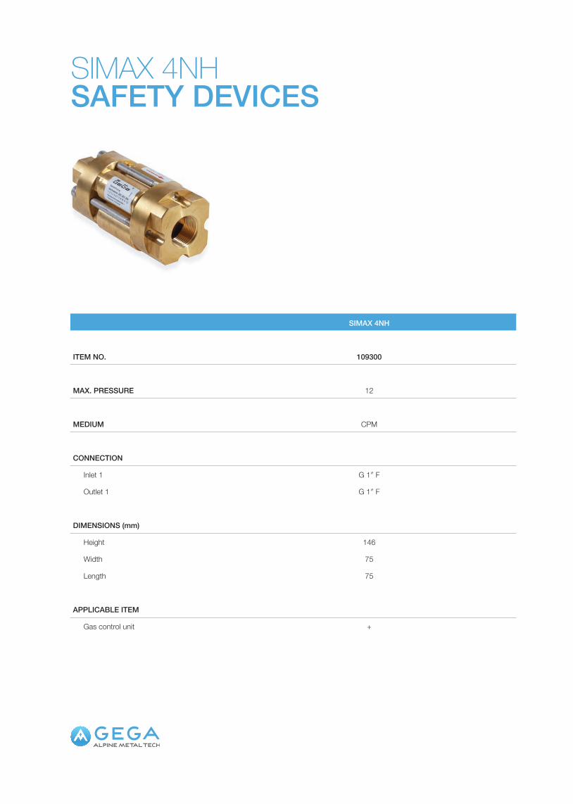
SIMAX 4NHSAFETY DEVICES
SIMAX 4NH
ITEM NO. 109300
MAX. PRESSURE 12
MEDIUM CPM
CONNECTION
Inlet 1 G 1″ F
Outlet 1 G 1″ F
DIMENSIONS (mm)
Height 146
Width 75
Length 75
APPLICABLE ITEM
Gas control unit +

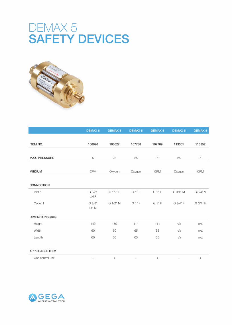
DEMAX 5SAFETY DEVICES
DEMAX 5 DEMAX 5 DEMAX 5 DEMAX 5 DEMAX 5 DEMAX 5
ITEM NO. 106626 106627 107788 107789 113351 113352
MAX. PRESSURE 5 25 25 5 25 5
MEDIUM CPM Oxygen Oxygen CPM Oxygen CPM
CONNECTION
Inlet 1 G 3/8″ LH F
G 1/2″ F G 1″ F G 1″ F G 3/4″ M G 3/4″ M
Outlet 1 G 3/8″ LH M
G 1/2″ M G 1″ F G 1″ F G 3/4" F G 3/4″ F
DIMENSIONS (mm)
Height 142 150 111 111 n/a n/a
Width 60 60 65 65 n/a n/a
Length 60 60 65 65 n/a n/a
APPLICABLE ITEM
Gas control unit + + + + + +

NON-RETURN DEVICESSAFETY EQUIPMENTFor large oxygen mass flows, AMT Gega offers simple non-return valves. These contain a standard flap controller to reduce losses. Therefore, machine pressures similar to the inlet pressures can be realised.

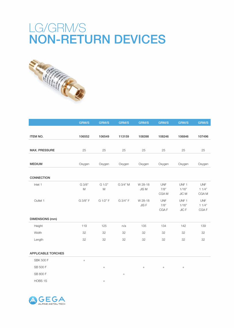
LG/GRM/SNON-RETURN DEVICES
GRM/S GRM/S GRM/S GRM/S GRM/S GRM/S GRM/S
ITEM NO. 106552 106549 113159 108398 108246 106846 107496
MAX. PRESSURE 25 25 25 25 25 25 25
MEDIUM Oxygen Oxygen Oxygen Oxygen Oxygen Oxygen Oxygen
CONNECTION
Inlet 1 G 3/8″ M
G 1/2″ M
G 3/4″ M W 28-18 JIS M
UNF 7/8″
CGA M
UNF 1 1/16″ JIC M
UNF 1 1/4″ CGA M
Outlet 1 G 3/8″ F G 1/2″ F G 3/4″ F W 28-18 JIS F
UNF 7/8″
CGA F
UNF 1 1/16″ JIC F
UNF 1 1/4″ CGA F
DIMENSIONS (mm)
Height 119 125 n/a 135 134 142 139
Width 32 32 32 32 32 32 32
Length 32 32 32 32 32 32 32
APPLICABLE TORCHES
SBK 500 F +
SB 500 F + + + +
SB 800 F +
HOBS 1S +

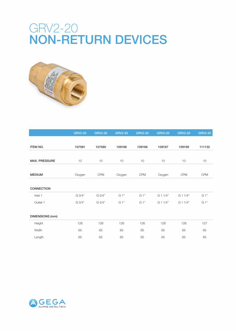
GRV2-20NON-RETURN DEVICES
GRV2-20 GRV2-20 GRV2-20 GRV2-20 GRV2-20 GRV2-20 GRV2-25
ITEM NO. 107581 107580 109166 109168 109167 109169 111132
MAX. PRESSURE 10 10 10 10 10 10 10
MEDIUM Oxygen CPM Oxygen CPM Oxygen CPM CPM
CONNECTION
Inlet 1 G 3/4″ G 3/4″ G 1″ G 1″ G 1 1/4″ G 1 1/4″ G 1″
Outlet 1 G 3/4″ G 3/4″ G 1″ G 1″ G 1 1/4″ G 1 1/4″ G 1″
DIMENSIONS (mm)
Height 126 126 126 126 126 126 127
Width 65 65 65 65 65 65 65
Length 65 65 65 65 65 65 65


HOSES2SS2SG2TE3TEPTFE
HOSES
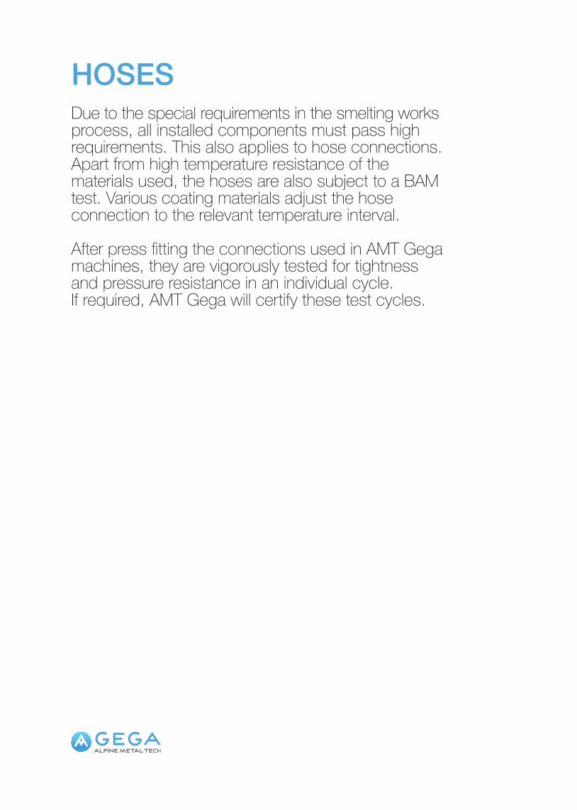
HOSESDue to the special requirements in the smelting works process, all installed components must pass high requirements. This also applies to hose connections. Apart from high temperature resistance of the materials used, the hoses are also subject to a BAM test. Various coating materials adjust the hose connection to the relevant temperature interval.
After press fitting the connections used in AMT Gega machines, they are vigorously tested for tightness and pressure resistance in an individual cycle. If required, AMT Gega will certify these test cycles.

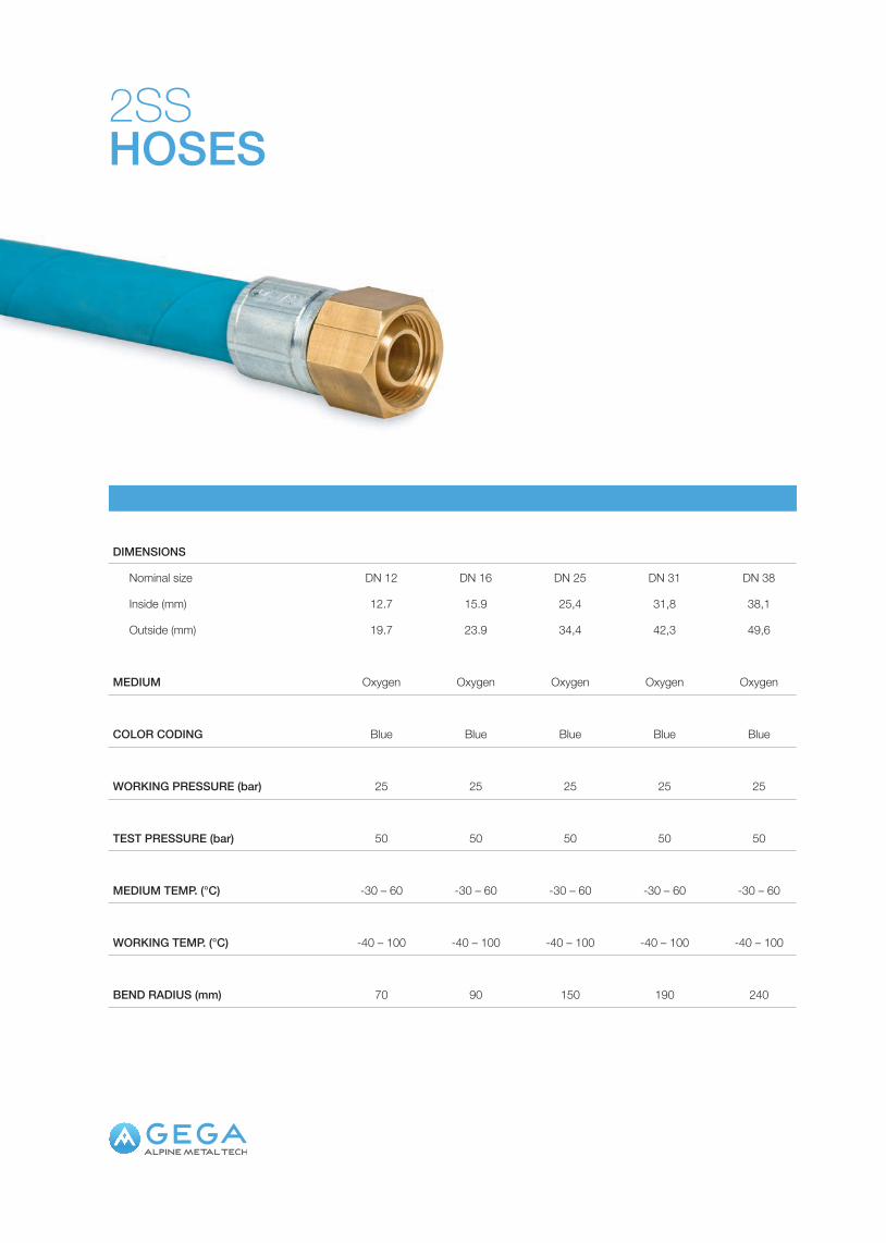
2SSHOSES
DIMENSIONS
Nominal size DN 12 DN 16 DN 25 DN 31 DN 38
Inside (mm) 12.7 15.9 25,4 31,8 38,1
Outside (mm) 19.7 23.9 34,4 42,3 49,6
MEDIUM Oxygen Oxygen Oxygen Oxygen Oxygen
COLOR CODING Blue Blue Blue Blue Blue
WORKING PRESSURE (bar) 25 25 25 25 25
TEST PRESSURE (bar) 50 50 50 50 50
MEDIUM TEMP. (°C) -30 – 60 -30 – 60 -30 – 60 -30 – 60 -30 – 60
WORKING TEMP. (°C) -40 – 100 -40 – 100 -40 – 100 -40 – 100 -40 – 100
BEND RADIUS (mm) 70 90 150 190 240

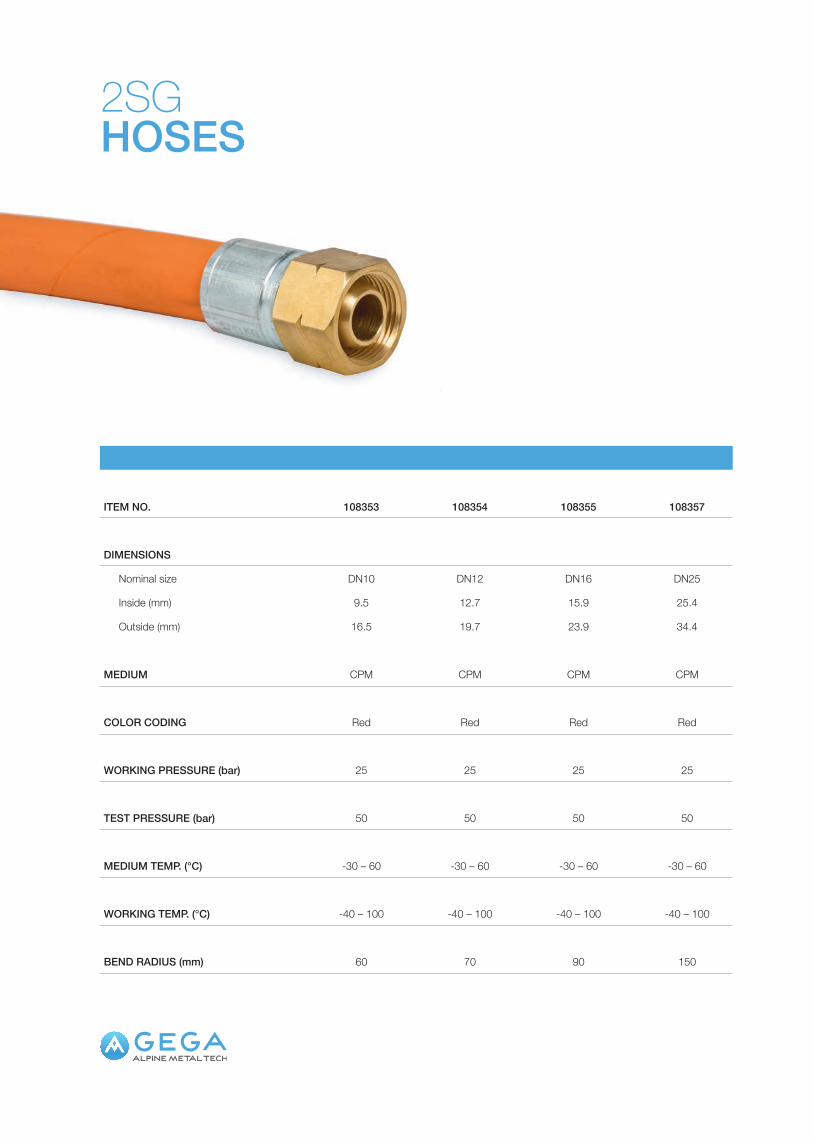
2SGHOSES
ITEM NO. 108353 108354 108355 108357
DIMENSIONS
Nominal size DN10 DN12 DN16 DN25
Inside (mm) 9.5 12.7 15.9 25.4
Outside (mm) 16.5 19.7 23.9 34.4
MEDIUM CPM CPM CPM CPM
COLOR CODING Red Red Red Red
WORKING PRESSURE (bar) 25 25 25 25
TEST PRESSURE (bar) 50 50 50 50
MEDIUM TEMP. (°C) -30 – 60 -30 – 60 -30 – 60 -30 – 60
WORKING TEMP. (°C) -40 – 100 -40 – 100 -40 – 100 -40 – 100
BEND RADIUS (mm) 60 70 90 150

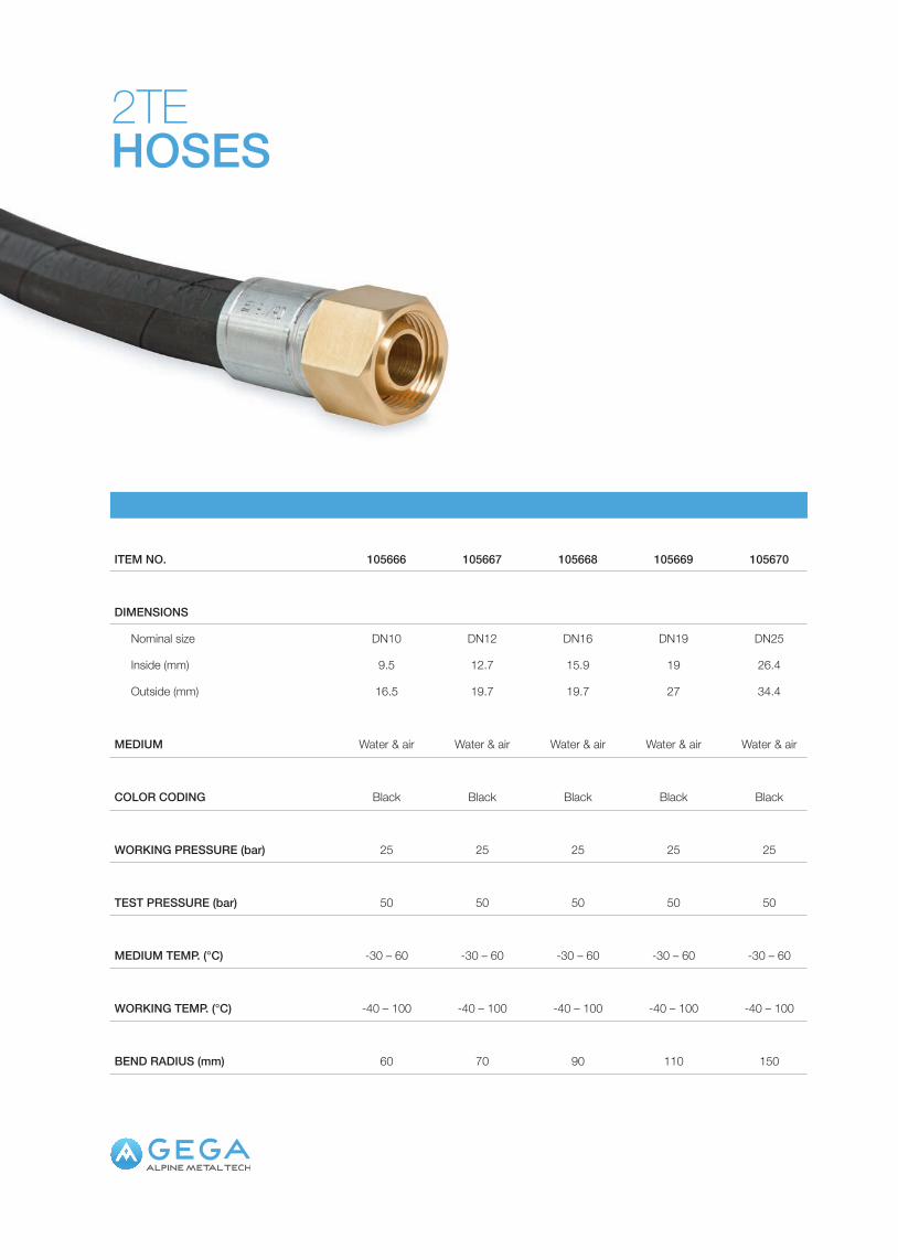
2TEHOSES
ITEM NO. 105666 105667 105668 105669 105670
DIMENSIONS
Nominal size DN10 DN12 DN16 DN19 DN25
Inside (mm) 9.5 12.7 15.9 19 26.4
Outside (mm) 16.5 19.7 19.7 27 34.4
MEDIUM Water & air Water & air Water & air Water & air Water & air
COLOR CODING Black Black Black Black Black
WORKING PRESSURE (bar) 25 25 25 25 25
TEST PRESSURE (bar) 50 50 50 50 50
MEDIUM TEMP. (°C) -30 – 60 -30 – 60 -30 – 60 -30 – 60 -30 – 60
WORKING TEMP. (°C) -40 – 100 -40 – 100 -40 – 100 -40 – 100 -40 – 100
BEND RADIUS (mm) 60 70 90 110 150

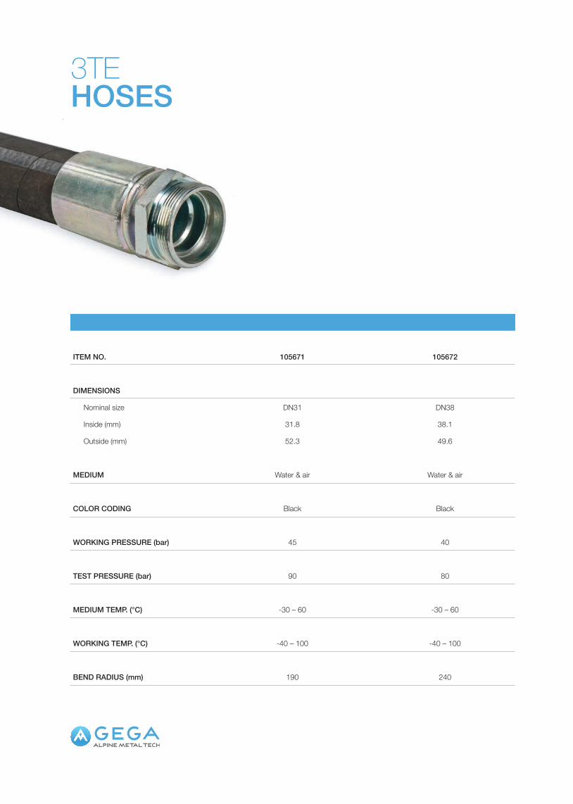
3TEHOSES
ITEM NO. 105671 105672
DIMENSIONS
Nominal size DN31 DN38
Inside (mm) 31.8 38.1
Outside (mm) 52.3 49.6
MEDIUM Water & air Water & air
COLOR CODING Black Black
WORKING PRESSURE (bar) 45 40
TEST PRESSURE (bar) 90 80
MEDIUM TEMP. (°C) -30 – 60 -30 – 60
WORKING TEMP. (°C) -40 – 100 -40 – 100
BEND RADIUS (mm) 190 240

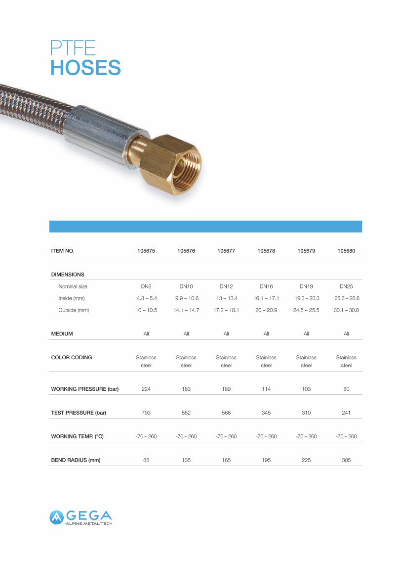
PTFEHOSES
ITEM NO. 105675 105676 105677 105678 105679 105680
DIMENSIONS
Nominal size DN6 DN10 DN12 DN16 DN19 DN25
Inside (mm) 4.8 – 5.4 9.9 – 10.6 13 – 13.4 16.1 – 17.1 19.3 – 20.3 25.6 – 26.6
Outside (mm) 10 – 10.5 14.1 – 14.7 17.2 – 18.1 20 – 20.9 24.5 – 25.5 30.1 – 30.8
MEDIUM All All All All All All
COLOR CODING Stainless steel
Stainless steel
Stainless steel
Stainless steel
Stainless steel
Stainless steel
WORKING PRESSURE (bar) 224 183 189 114 103 80
TEST PRESSURE (bar) 793 552 566 345 310 241
WORKING TEMP. (°C) -70 – 260 -70 – 260 -70 – 260 -70 – 260 -70 – 260 -70 – 260
BEND RADIUS (mm) 85 135 165 195 225 305

MOBILE EQUIPMENTCortiCorti gas control panel
MO
BILEEQ
UIPMENT
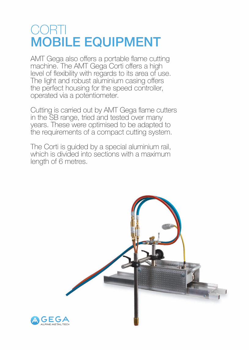
CORTIMOBILE EQUIPMENTAMT Gega also offers a portable flame cutting machine. The AMT Gega Corti offers a high level of flexibility with regards to its area of use. The light and robust aluminium casing offers the perfect housing for the speed controller, operated via a potentiometer.
Cutting is carried out by AMT Gega flame cutters in the SB range, tried and tested over many years. These were optimised to be adapted to the requirements of a compact cutting system.
The Corti is guided by a special aluminium rail, which is divided into sections with a maximum length of 6 metres.
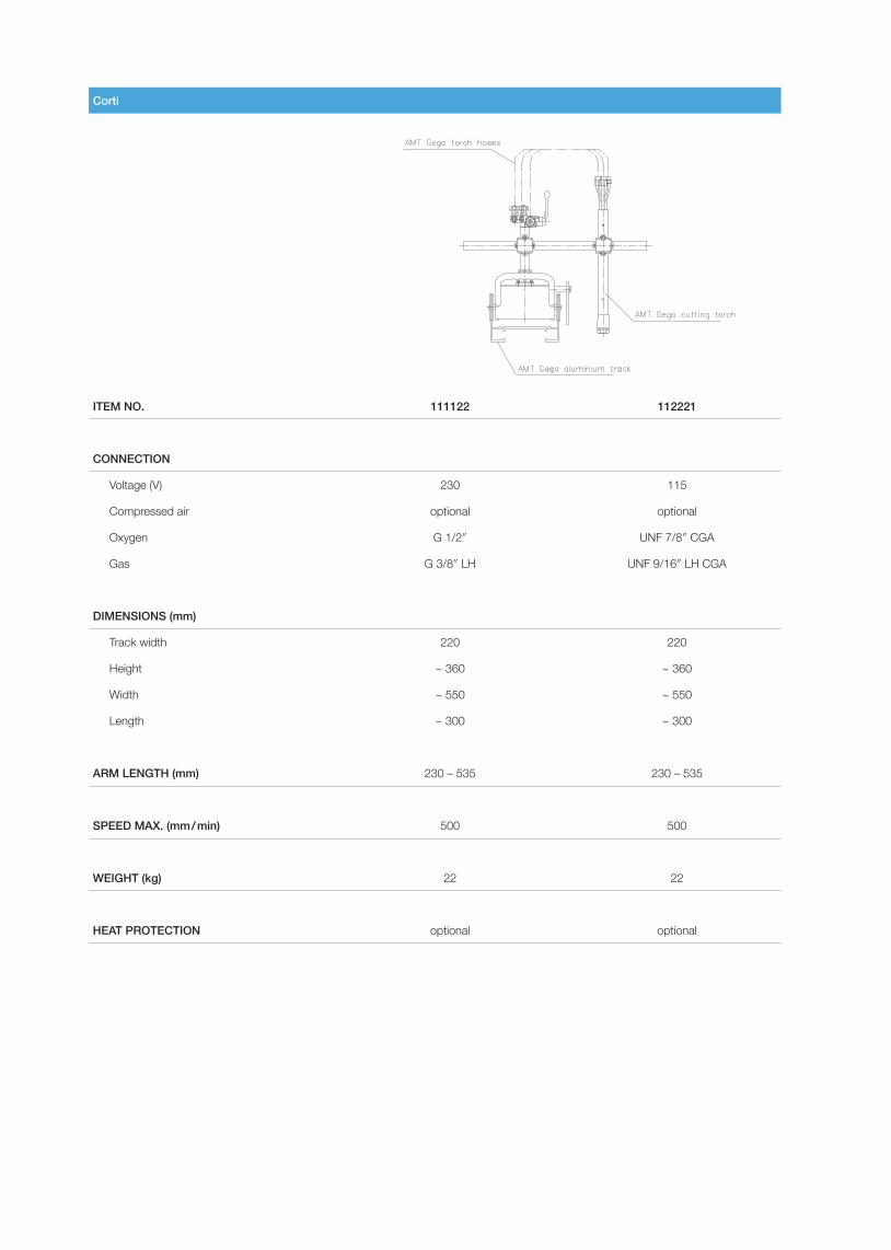
Corti
ITEM NO. 111122 112221
CONNECTION
Voltage (V) 230 115
Compressed air optional optional
Oxygen G 1/2″ UNF 7/8″ CGA
Gas G 3/8″ LH UNF 9/16″ LH CGA
DIMENSIONS (mm)
Track width 220 220
Height ~ 360 ~ 360
Width ~ 550 ~ 550
Length ~ 300 ~ 300
ARM LENGTH (mm) 230 – 535 230 – 535
SPEED MAX. (mm / min) 500 500
WEIGHT (kg) 22 22
HEAT PROTECTION optional optional
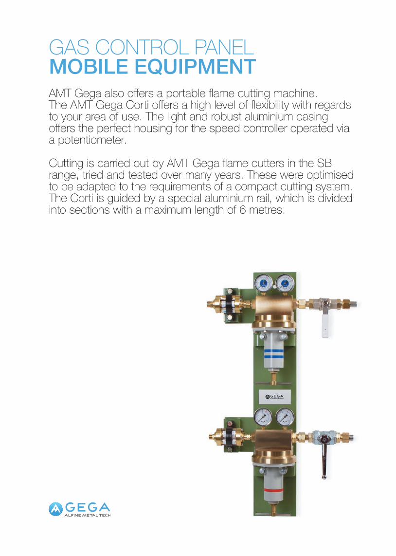
GAS CONTROL PANELMOBILE EQUIPMENTAMT Gega also offers a portable flame cutting machine. The AMT Gega Corti offers a high level of flexibility with regards to your area of use. The light and robust aluminium casing offers the perfect housing for the speed controller operated via a potentiometer.
Cutting is carried out by AMT Gega flame cutters in the SB range, tried and tested over many years. These were optimised to be adapted to the requirements of a compact cutting system.The Corti is guided by a special aluminium rail, which is divided into sections with a maximum length of 6 metres.
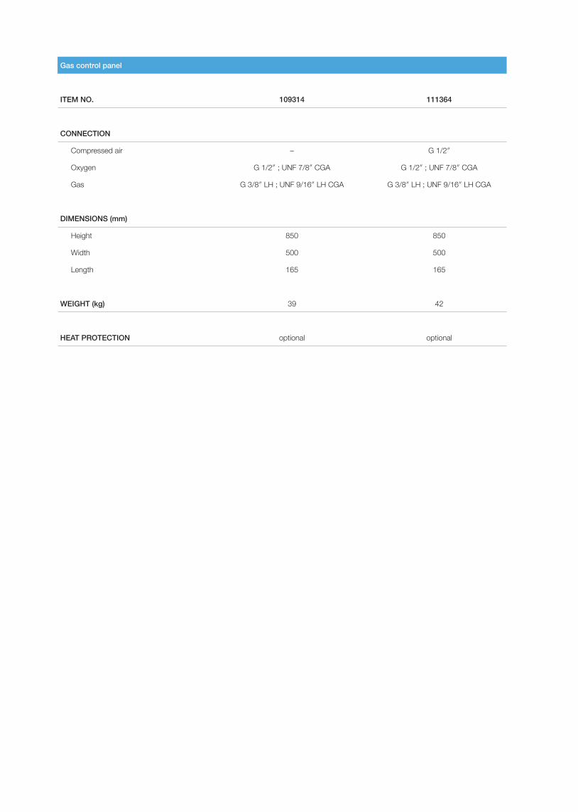
Gas control panel
ITEM NO. 109314 111364
CONNECTION
Compressed air – G 1/2″
Oxygen G 1/2″ ; UNF 7/8″ CGA G 1/2″ ; UNF 7/8″ CGA
Gas G 3/8″ LH ; UNF 9/16″ LH CGA G 3/8″ LH ; UNF 9/16″ LH CGA
DIMENSIONS (mm)
Height 850 850
Width 500 500
Length 165 165
WEIGHT (kg) 39 42
HEAT PROTECTION optional optional
ADDITIONAL EQUIPMENTPowder equipmentNozzle seat reamerMeasuring deviceRepair kits / Gasket kitsPressure gauge
ADDITIONAL
EQUIPM
ENT
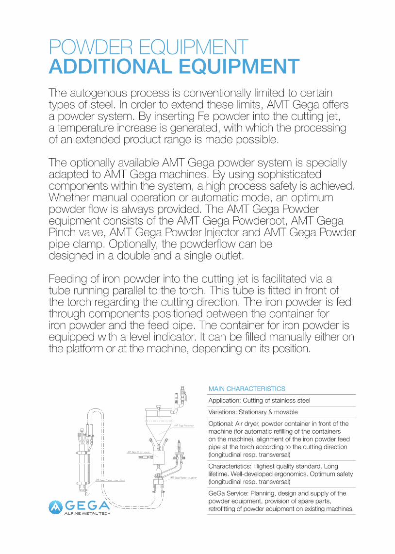
POWDER EQUIPMENTADDITIONAL EQUIPMENTThe autogenous process is conventionally limited to certain types of steel. In order to extend these limits, AMT Gega offers a powder system. By inserting Fe powder into the cutting jet, a temperature increase is generated, with which the processing of an extended product range is made possible.
The optionally available AMT Gega powder system is specially adapted to AMT Gega machines. By using sophisticated components within the system, a high process safety is achieved. Whether manual operation or automatic mode, an optimum powder flow is always provided. The AMT Gega Powder equipment consists of the AMT Gega Powderpot, AMT Gega Pinch valve, AMT Gega Powder Injector and AMT Gega Powder pipe clamp. Optionally, the powderflow can be designed in a double and a single outlet.
Feeding of iron powder into the cutting jet is facilitated via a tube running parallel to the torch. This tube is fitted in front of the torch regarding the cutting direction. The iron powder is fed through components positioned between the container for iron powder and the feed pipe. The container for iron powder is equipped with a level indicator. It can be filled manually either on the platform or at the machine, depending on its position.
MAIN CHARACTERISTICS
Application: Cutting of stainless steelVariations: Stationary & movableOptional: Air dryer, powder container in front of the machine (for automatic refilling of the containers on the machine), alignment of the iron powder feed pipe at the torch according to the cutting direction (longitudinal resp. transversal)Characteristics: Highest quality standard. Long lifetime. Well-developed ergonomics. Optimum safety (longitudinal resp. transversal)GeGa Service: Planning, design and supply of the powder equipment, provision of spare parts, retrofitting of powder equipment on existing machines.

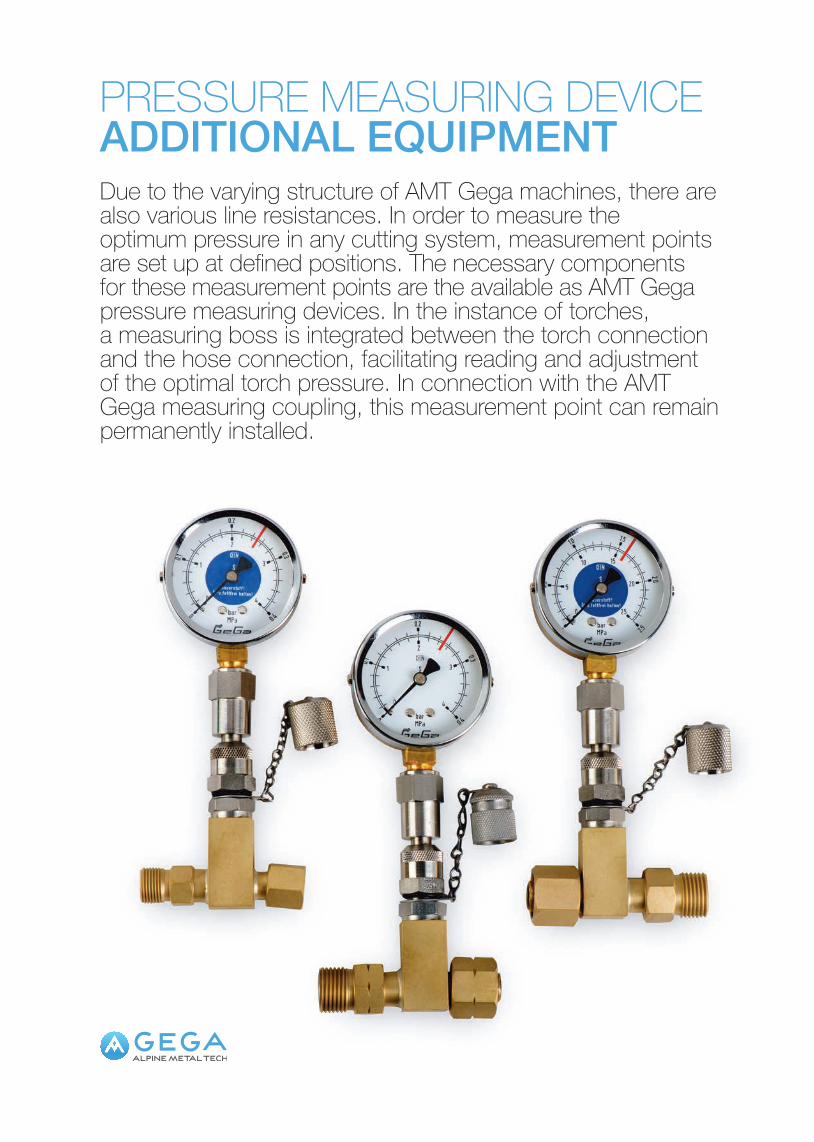
PRESSURE MEASURING DEVICEADDITIONAL EQUIPMENTDue to the varying structure of AMT Gega machines, there are also various line resistances. In order to measure the optimum pressure in any cutting system, measurement points are set up at defined positions. The necessary components for these measurement points are the available as AMT Gega pressure measuring devices. In the instance of torches, a measuring boss is integrated between the torch connection and the hose connection, facilitating reading and adjustment of the optimal torch pressure. In connection with the AMT Gega measuring coupling, this measurement point can remain permanently installed.
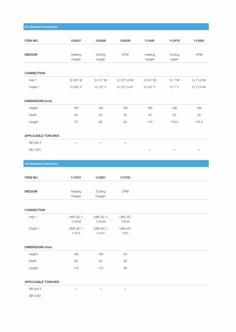
EU standard connection
ITEM NO. 103507 103508 103509 112481 112479 112480
MEDIUM Heating oxygen
Cuttingoxygen
CPM Heating oxygen
Cuttingxygen
CPM
CONNECTION
Inlet 1 G 3/8″ M G 1/2″ M G 1/2″ LH M G 3/4″ M G 1″ M G 1″LH M
Outlet 1 G 3/8″ F G 1/2″ F G 1/2″ LH F G 3/4″ F G 1″ F G 1″LH M
DIMENSIONS (mm)
Height 180 180 180 180 180 185
Width 20 20 20 30 30 30
Length 72 82 82 110 116.5 116.5
APPLICABLE TORCHES
SB 500 F + + +
SB 1200 + + +
US standard connection
ITEM NO. 112701 112831 112702
MEDIUM Heating Oxygen
CuttingOxygen
CPM
CONNECTION
Inlet 1 UNF/JIC 1 1/16 M
UNF/JIC 1 1/16 M
UNF/JIC 7/8 M
Outlet 1 UNF/JIC 1 1/16 F
UNF/JIC 1 1/16 F
UNF/JIC 7/8 F
DIMENSIONS (mm)
Height 185 185 181
Width 20 20 20
Length 110 110 90
APPLICABLE TORCHES
SB 500 F + + +
SB 1200
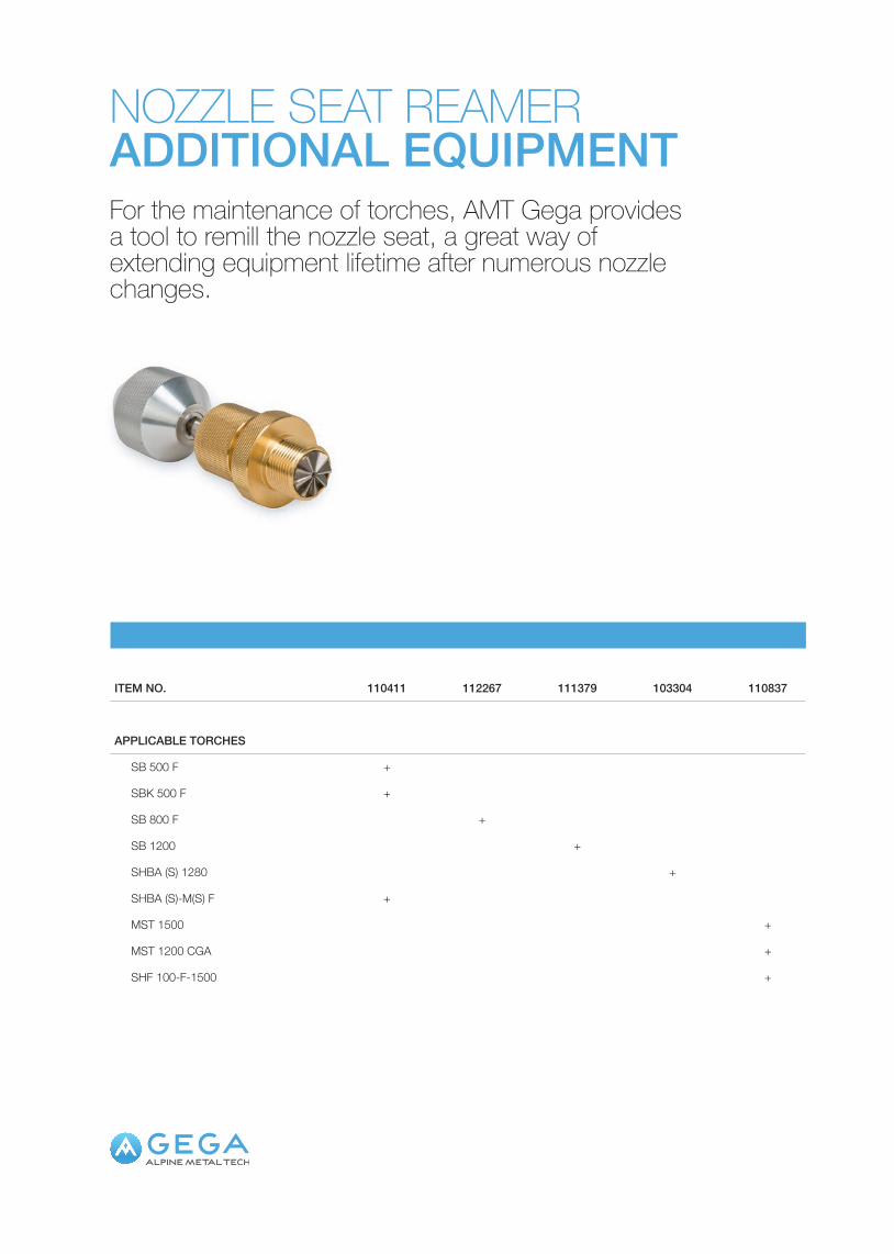
NOZZLE SEAT REAMERADDITIONAL EQUIPMENTFor the maintenance of torches, AMT Gega provides a tool to remill the nozzle seat, a great way of extending equipment lifetime after numerous nozzle changes.
ITEM NO. 110411 112267 111379 103304 110837
APPLICABLE TORCHES
SB 500 F +
SBK 500 F +
SB 800 F +
SB 1200 +
SHBA (S) 1280 +
SHBA (S)-M(S) F +
MST 1500 +
MST 1200 CGA +
SHF 100-F-1500 +

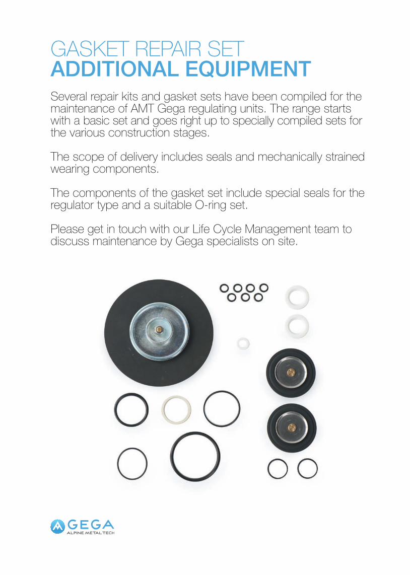
GASKET REPAIR SETADDITIONAL EQUIPMENTSeveral repair kits and gasket sets have been compiled for the maintenance of AMT Gega regulating units. The range starts with a basic set and goes right up to specially compiled sets for the various construction stages.
The scope of delivery includes seals and mechanically strained wearing components.
The components of the gasket set include special seals for the regulator type and a suitable O-ring set.
Please get in touch with our Life Cycle Management team to discuss maintenance by Gega specialists on site.
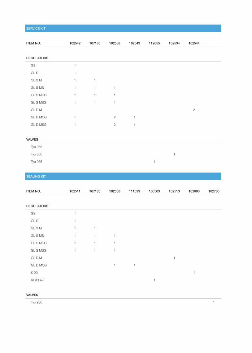
SERVICE KIT
ITEM NO. 102542 107185 102538 102543 112655 102534 102544
REGULATORS
GS 1
GL S 1
GL S M 1 1
GL S MS 1 1 1
GL S MCG 1 1 1
GL S MSG 1 1 1
GL D M 2
GL D MCG 1 2 1
GL D MSG 1 2 1
VALVES
Typ 966
Typ 880 1
Typ 955 1
SEALING KIT
ITEM NO. 102511 107185 102538 111099 106503 102513 102686 102760
REGULATORS
GS 1
GL S 1
GL S M 1 1
GL S MS 1 1 1
GL S MCG 1 1 1
GL S MSG 1 1 1
GL D M 1
GL D MCG 1 1
K 20 1
KB(S) 42 1
VALVES
Typ 966 1
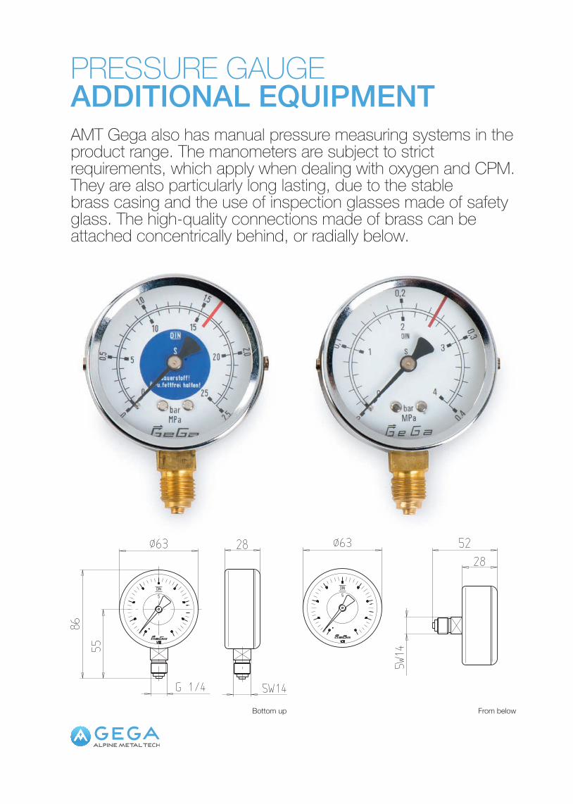
PRESSURE GAUGEADDITIONAL EQUIPMENTAMT Gega also has manual pressure measuring systems in the product range. The manometers are subject to strict requirements, which apply when dealing with oxygen and CPM. They are also particularly long lasting, due to the stable brass casing and the use of inspection glasses made of safety glass. The high-quality connections made of brass can be attached concentrically behind, or radially below.
From belowBottom up
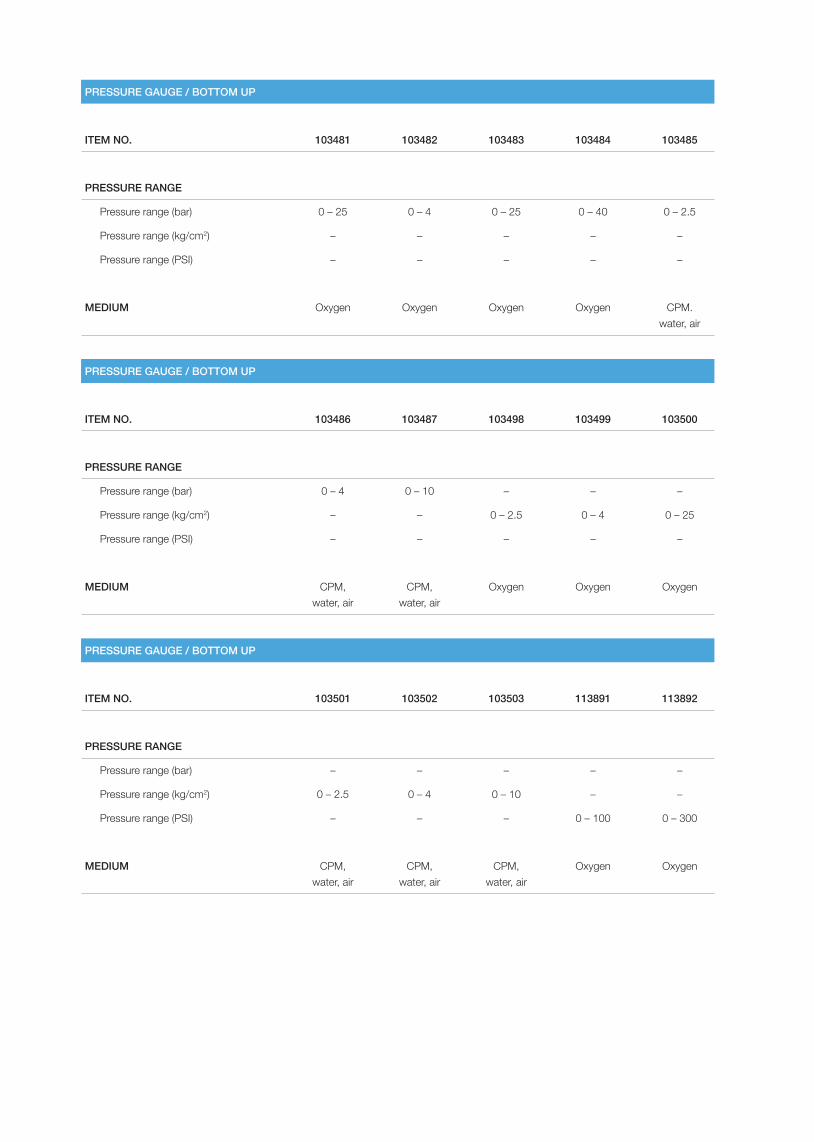
PRESSURE GAUGE / BOTTOM UP
ITEM NO. 103481 103482 103483 103484 103485
PRESSURE RANGE
Pressure range (bar) 0 – 25 0 – 4 0 – 25 0 – 40 0 – 2.5
Pressure range (kg/cm2) – – – – –
Pressure range (PSI) – – – – –
MEDIUM Oxygen Oxygen Oxygen Oxygen CPM. water, air
PRESSURE GAUGE / BOTTOM UP
ITEM NO. 103486 103487 103498 103499 103500
PRESSURE RANGE
Pressure range (bar) 0 – 4 0 – 10 – – –
Pressure range (kg/cm2) – – 0 – 2.5 0 – 4 0 – 25
Pressure range (PSI) – – – – –
MEDIUM CPM, water, air
CPM, water, air
Oxygen Oxygen Oxygen
PRESSURE GAUGE / BOTTOM UP
ITEM NO. 103501 103502 103503 113891 113892
PRESSURE RANGE
Pressure range (bar) – – – – –
Pressure range (kg/cm2) 0 – 2.5 0 – 4 0 – 10 – –
Pressure range (PSI) – – – 0 – 100 0 – 300
MEDIUM CPM, water, air
CPM, water, air
CPM, water, air
Oxygen Oxygen
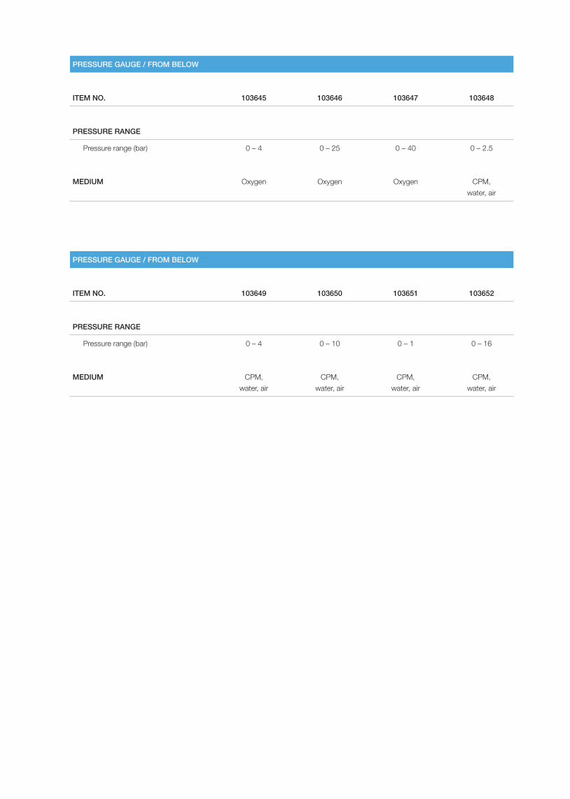
PRESSURE GAUGE / FROM BELOW
ITEM NO. 103645 103646 103647 103648
PRESSURE RANGE
Pressure range (bar) 0 – 4 0 – 25 0 – 40 0 – 2.5
MEDIUM Oxygen Oxygen Oxygen CPM, water, air
PRESSURE GAUGE / FROM BELOW
ITEM NO. 103649 103650 103651 103652
PRESSURE RANGE
Pressure range (bar) 0 – 4 0 – 10 0 – 1 0 – 16
MEDIUM CPM, water, air
CPM, water, air
CPM, water, air
CPM, water, air


SERVICE
SERVICE

MAINTENANCE & LIFECYCLE MANAGEMENTSERVICEWe are in a pretty tough business. No doubt about it. Day in and day out, we work under the most gruelling circumstances: Delivering consistency. Speed. Precision. In sweltering heat and pitch dark. The reason we are on top? Because we are tougher. As an additional option, you can also have your regulating stations maintained and repaired by AMT Gega technicians.
Gega machines and components are renown for their extraordinary long lifetime. This makes spending an extra thought on maintenance and service all the more worthwhile. We are proud to support our clients‘ daily operations with efficient replacement schemes to ensure maximum equipment readiness. Our experts stand by with legendary in-depth knowledge and years of experience.
Over 40 subsidiaries around the globe ensure that a Gega specialist can join you on site whenver the situation requires immediate attention. Once the end of a life cycle is approached, Gega will assist you with the planning of refurbishment, temporary replacement and back-up of entire machines.
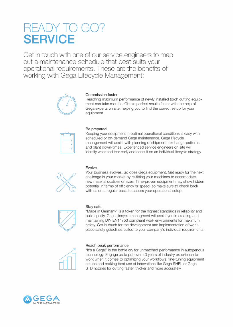
Commission faster
Reaching maximum performance of newly installed torch cutting equip-ment can take months. Obtain perfect results faster with the help of Gega experts on site, helping you to find the correct setup for your equipment.
Be prepared
Keeping your equipment in optimal operational conditions is easy with scheduled or on-demand Gega maintenance. Gega lifecycle management will assist with planning of shipment, exchange-patterns and plant down-times. Experienced service engineers on site will identify wear and tear early and consult on an individual lifecycle strategy.
Evolve
Your business evolves. So does Gega equipment. Get ready for the next challenge in your market by re-fitting your machines to accomodate new material qualities or sizes. Time-proven equipment may show hidden potential in terms of efficiency or speed, so make sure to check back with us on a regular basis to assess your operational setup.
Stay safe
“Made in Germany” is a token for the highest standards in reliability and build quality. Gega lifecycle managment will assist you in creating and maintaining DIN EN14753 compliant work environments for maximum safety. Get in touch for the development and implementation of work- place safety guidelines suited to your company‘s individual requirements.
Reach peak performance
“It‘s a Gega!” is the battle cry for unmatched performance in autogenous technology. Engage us to put over 40 years of industry experience to work when it comes to optimizing your workflows, fine-tuning equipment setups and making best use of innovations like Gega SHEL or Gega STD nozzles for cutting faster, thicker and more accurately.
READY TO GO?SERVICEGet in touch with one of our service engineers to map out a maintenance schedule that best suits your operational requirements. These are the benefits of working with Gega Lifecycle Management:
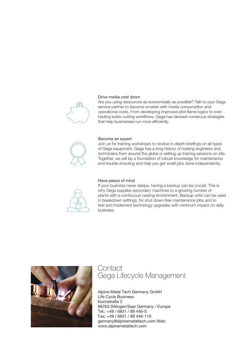
ContactGega Lifecycle Management
Alpine Metal Tech Germany GmbHLife Cycle BusinessKochstraße 266763 Dillingen/Saar Germany / EuropeTel.: +49 / 6831 / 89 446-0Fax: +49 / 6831 / 89 446-110 [email protected] Web: www.alpinemetaltech.com
Become an expert
Join us for training workshops to receive in-depth briefings on all types of Gega equipment. Gega has a long history of hosting engineers and technicians from around the globe or setting up training sessions on site. Together, we will lay a foundation of robust knowledge for maintenance and trouble-shooting and help you get small jobs done independently.
Have peace of mind
If your business never sleeps, having a backup can be crucial. This is why Gega supplies secondary machines to a growing number of plants with a continuous casting environment. Backup units can be used in breakdown settings, for shut down-free maintenance jobs and to test and implement technology upgrades with minimum impact on daily business.
Drive media cost down
Are you using ressources as economically as possible? Talk to your Gega service partner to become smarter with media consumption and operational costs. From developing improved pilot flame logics to over-hauling entire cutting workflows, Gega has devised numerous strategies that help businesses run more efficiently.
CONTACT
GEGA HEADQUARTERS
Alpine Metal Tech Germany GmbHKochstraße 2, 66763 Dillingen/Saar Germany / EuropeTel.: +49 / 6831 / 89 446-0Fax: +49 / 6831 / 89 [email protected]: www.alpinemetaltech.com