1450/850 - Ladders | Loft Ladders | Scaffold Towers | … · The 1450/850 tower is manufactured to...
17
1450/850 A SAFER WAY TO REACH NEW HEIGHTS Instrucon Manual Mobile Access Tower 3T - Through the trap method This Assembly Guide is intended to provide you with step-by-step instrucons on how to erect your Mobile Access Tower (MAT) with ease and safety, using the 3T (through the trap) method. You should read and understand all notes and diagrams, including the parts list for each height, before commencing assembly. Personnel should be qualified or competent to erect this tower. Please consult the PASMA Guide for full information on the use of Mobile Access Towers. Remember to do a risk assessment of the area where the tower is to be used before commencing erection. Introducon Supplied by BPS Access Solutions Ltd Tel. +44 (0) 333 006 9776 Fax +44 (0) 1959 572 932 www.laddersandscaffoldtowers.co.uk KM 617169 1
Transcript of 1450/850 - Ladders | Loft Ladders | Scaffold Towers | … · The 1450/850 tower is manufactured to...
1450/850A SAFER WAY TO REACH NEW HEIGHTS
Instruction ManualMobile Access Tower3T - Through the trap method
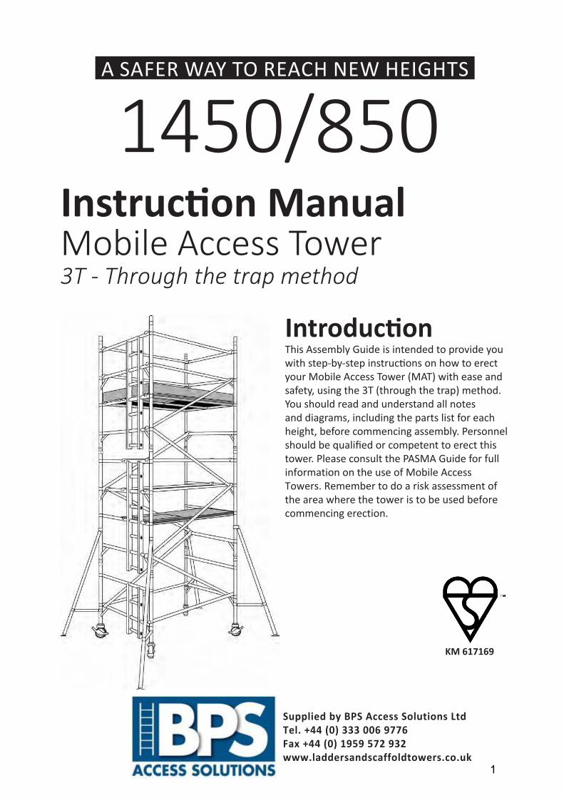
This Assembly Guide is intended to provide you with step-by-step instructions on how to erect your Mobile Access Tower (MAT) with ease and safety, using the 3T (through the trap) method. You should read and understand all notes and diagrams, including the parts list for each height, before commencing assembly. Personnel should be qualified or competent to erect this tower. Please consult the PASMA Guide for full information on the use of Mobile Access Towers. Remember to do a risk assessment of the area where the tower is to be used before commencing erection.
Introduction
Supplied by BPS Access Solutions Ltd Tel. +44 (0) 333 006 9776 Fax +44 (0) 1959 572 932 www.laddersandscaffoldtowers.co.uk
KM 617169
1
1450/850A SAFER WAY TO REACH NEW HEIGHTS
Instruction ManualMobile Access Tower
Description, Safety Notes and Fittings 3Components 7Assembly 8Dismantling 15Risk Assessment Form 18
Contents
Manufactured by UTS SALES & REPAIR
2
Manufactured to BS EN 1004:2004 Class 3 8/12 XXXD Instruction Manual BS: EN: 1298-IM-EN
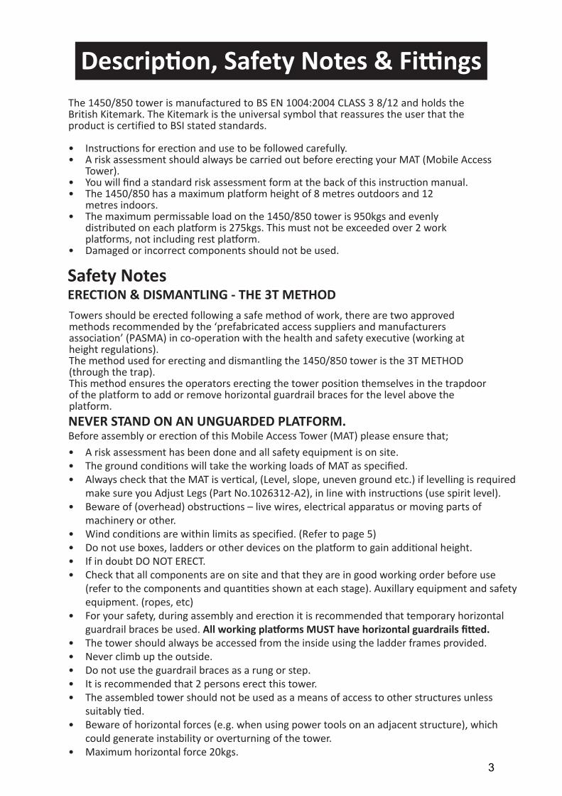
Description, Safety Notes & FittingsThe 1450/850 tower is manufactured to BS EN 1004:2004 CLASS 3 8/12 and holds the British Kitemark. The Kitemark is the universal symbol that reassures the user that the product is certified to BSI stated standards.
• Instructions for erection and use to be followed carefully.• A risk assessment should always be carried out before erecting your MAT (Mobile Access
Tower).• You will find a standard risk assessment form at the back of this instruction manual.• The 1450/850 has a maximum platform height of 8 metres outdoors and 12
metres indoors.• The maximum permissable load on the 1450/850 tower is 950kgs and evenly
distributed on each platform is 275kgs. This must not be exceeded over 2 work platforms, not including rest platform.
• Damaged or incorrect components should not be used.
Towers should be erected following a safe method of work, there are two approved methods recommended by the ‘prefabricated access suppliers and manufacturers association’ (PASMA) in co-operation with the health and safety executive (working at height regulations).The method used for erecting and dismantling the 1450/850 tower is the 3T METHOD (through the trap).This method ensures the operators erecting the tower position themselves in the trapdoor of the platform to add or remove horizontal guardrail braces for the level above the platform.
• A risk assessment has been done and all safety equipment is on site.• The ground conditions will take the working loads of MAT as specified.• Always check that the MAT is vertical, (Level, slope, uneven ground etc.) if levelling is required
make sure you Adjust Legs (Part No.1026312-A2), in line with instructions (use spirit level).• Beware of (overhead) obstructions – live wires, electrical apparatus or moving parts of
machinery or other.• Wind conditions are within limits as specified. (Refer to page 5)• Do not use boxes, ladders or other devices on the platform to gain additional height.• If in doubt DO NOT ERECT.• Check that all components are on site and that they are in good working order before use
(refer to the components and quantities shown at each stage). Auxillary equipment and safetyequipment. (ropes, etc)
• For your safety, during assembly and erection it is recommended that temporary horizontalguardrail braces be used. All working platforms MUST have horizontal guardrails fitted.
• The tower should always be accessed from the inside using the ladder frames provided.• Never climb up the outside.• Do not use the guardrail braces as a rung or step.• It is recommended that 2 persons erect this tower.• The assembled tower should not be used as a means of access to other structures unless
suitably tied.• Beware of horizontal forces (e.g. when using power tools on an adjacent structure), which
could generate instability or overturning of the tower.• Maximum horizontal force 20kgs.
Safety NotesERECTION & DISMANTLING - THE 3T METHOD
NEVER STAND ON AN UNGUARDED PLATFORM.Before assembly or erection of this Mobile Access Tower (MAT) please ensure that;
3
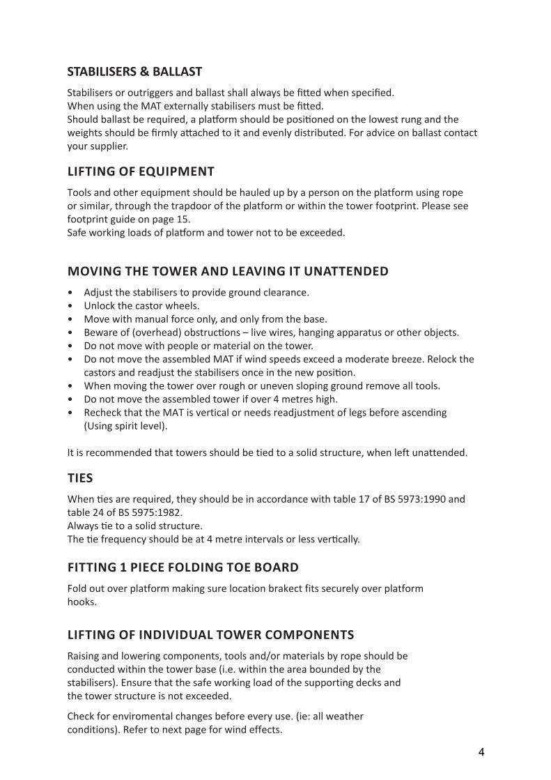
STABILISERS & BALLAST
LIFTING OF EQUIPMENT
MOVING THE TOWER AND LEAVING IT UNATTENDED
TIES
Stabilisers or outriggers and ballast shall always be fitted when specified.When using the MAT externally stabilisers must be fitted.Should ballast be required, a platform should be positioned on the lowest rung and the weights should be firmly attached to it and evenly distributed. For advice on ballast contact your supplier.
Tools and other equipment should be hauled up by a person on the platform using rope or similar, through the trapdoor of the platform or within the tower footprint. Please see footprint guide on page 15.Safe working loads of platform and tower not to be exceeded.
• Adjust the stabilisers to provide ground clearance.• Unlock the castor wheels.• Move with manual force only, and only from the base.• Beware of (overhead) obstructions – live wires, hanging apparatus or other objects.• Do not move with people or material on the tower.• Do not move the assembled MAT if wind speeds exceed a moderate breeze. Relock the
castors and readjust the stabilisers once in the new position.• When moving the tower over rough or uneven sloping ground remove all tools.• Do not move the assembled tower if over 4 metres high.• Recheck that the MAT is vertical or needs readjustment of legs before ascending
(Using spirit level).
It is recommended that towers should be tied to a solid structure, when left unattended.
When ties are required, they should be in accordance with table 17 of BS 5973:1990 andtable 24 of BS 5975:1982.Always tie to a solid structure.The tie frequency should be at 4 metre intervals or less vertically.
FITTING 1 PIECE FOLDING TOE BOARDFold out over platform making sure location brakect fits securely over platform hooks.
LIFTING OF INDIVIDUAL TOWER COMPONENTSRaising and lowering components, tools and/or materials by rope should be conducted within the tower base (i.e. within the area bounded by the stabilisers). Ensure that the safe working load of the supporting decks and the tower structure is not exceeded.
Check for enviromental changes before every use. (ie: all weather conditions). Refer to next page for wind effects.
4
CHECKLIST, INSPECTION, CARE AND MAINTENANCE FOR MOBILE ACCESS TOWERS• All components should be inspected before use to ensure that they are not damaged or
broken, particularly the welds.• ANY damage to ANY part particularly tubular members, castors, platform decking MUST
be replaced.• Adjustable leg threads should be cleaned and lightly oiled.• All locking claws on braces should be cleaned and the locking mechanism checked for operation.• When storing your MAT, please ensure that all components are neatly stored and not left
where they could get damaged.• When transporting the MAT always tie the components down so that they do not move
around and get damaged.• Should the tower be left unattended it should be tied to a suitable structure. Before using the
tower again ALWAYS check that the tower is vertical, undamaged and complete before ascending• The MAT is not designed to be lifted or suspended as a complete structure.• Always keep this instruction manual safe.• Broken, damaged or incorrect componnents must never be used. The equipment shall
be quarantined and assessed for replacement repair or destruction.
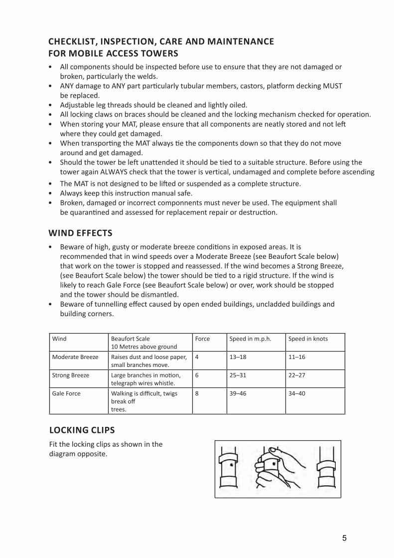
WIND EFFECTS
LOCKING CLIPS
• Beware of high, gusty or moderate breeze conditions in exposed areas. It isrecommended that in wind speeds over a Moderate Breeze (see Beaufort Scale below)that work on the tower is stopped and reassessed. If the wind becomes a Strong Breeze,(see Beaufort Scale below) the tower should be tied to a rigid structure. If the wind islikely to reach Gale Force (see Beaufort Scale below) or over, work should be stoppedand the tower should be dismantled.
• Beware of tunnelling effect caused by open ended buildings, uncladded buildings andbuilding corners.
Fit the locking clips as shown in thediagram opposite.
Wind Beaufort Scale10 Metres above ground
Force Speed in m.p.h. Speed in knots
Moderate Breeze Raises dust and loose paper,small branches move.
4 13–18 11–16
Strong Breeze Large branches in motion,telegraph wires whistle.
6 25–31 22–27
Gale Force Walking is difficult, twigs break offtrees.
8 39–46 34–40
5

LOCKING CASTORSCastor wheels should be pointed outwards atapproximately 45 degrees and locks engaged asshown opposite.
Press to engage — lift to disengage
FITTING STABILISERS
CORRECT FITTING OF HORIZONTAL BRACES
Attach a stabiliser to each corner of the tower at approximately 45 degrees for maximum stability and attach the clamps. Make sure that all stabilisers are firmly in contact with the ground before using the structure. Refer to page 15 for full details and illustrations on correct pratice.
THE CORRECT FITTING OF HORIZONTAL BRACES IS IMPORTANT.The diagrams opposite illustrate the CORRECT brace positions. REMEMBER: Always fit braces DOWNWARDS or from the inside of the tower facing OUTWARDS. NEVER attach braces facing INWARDS.
BRACE CLAMP LOCKING
FITTING ADJUSTABLE LEGS
Ensure that the brace clamp is locked as shown in diagrams opposite. Always make sure the brace is not clamped too close to the weld on the frame as indicated by the arrow shown.
Ensure all adjusting nuts are wound down to the castor and slide them into the bottom of the tower frame. Turn the frame the right way up and with the aid of a spirit level placed on the tower use the adjusting nuts to level the structure. DO NOT use leg adjustment to gain additional height.
Un-Locked Locked
6
OutwardsDownwards
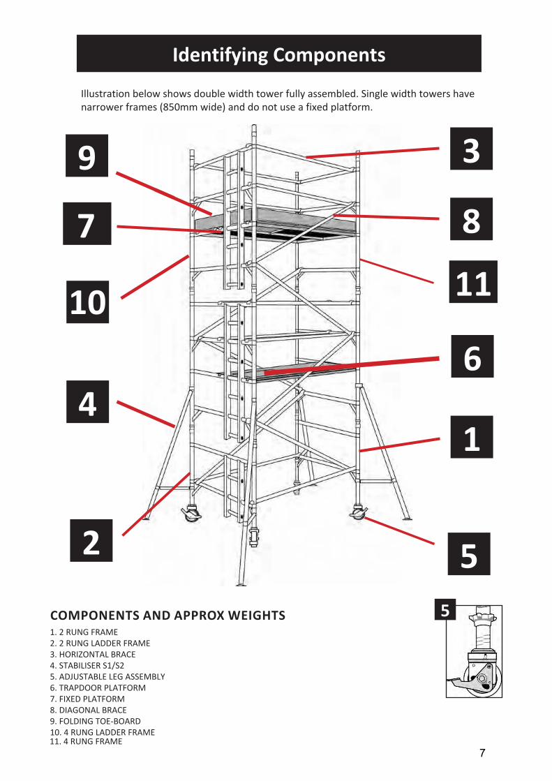
Identifying Components
COMPONENTS AND APPROX WEIGHTS1. 2 RUNG FRAME2. 2 RUNG LADDER FRAME3. HORIZONTAL BRACE4. STABILISER S1/S25. ADJUSTABLE LEG ASSEMBLY6. TRAPDOOR PLATFORM7. FIXED PLATFORM8. DIAGONAL BRACE9. FOLDING TOE-BOARD10. 4 RUNG LADDER FRAME
9
10
4
2
3
8
6
11
1
55
7
7
11. 4 RUNG FRAME
Illustration below shows double width tower fully assembled. Single width towers have narrower frames (850mm wide) and do not use a fixed platform.
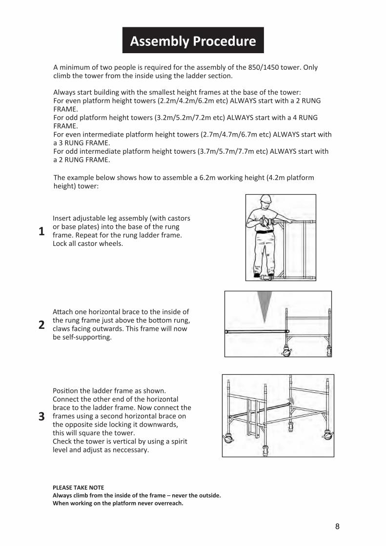
Assembly Procedure
A minimum of two people is required for the assembly of the 850/1450 tower. Only climb the tower from the inside using the ladder section.
Always start building with the smallest height frames at the base of the tower:For even platform height towers (2.2m/4.2m/6.2m etc) ALWAYS start with a 2 RUNG FRAME. For odd platform height towers (3.2m/5.2m/7.2m etc) ALWAYS start with a 4 RUNG FRAME.For even intermediate platform height towers (2.7m/4.7m/6.7m etc) ALWAYS start with a 3 RUNG FRAME.For odd intermediate platform height towers (3.7m/5.7m/7.7m etc) ALWAYS start with a 2 RUNG FRAME.
Insert adjustable leg assembly (with castors or base plates) into the base of the rung frame. Repeat for the rung ladder frame. Lock all castor wheels.
Attach one horizontal brace to the inside ofthe rung frame just above the bottom rung,claws facing outwards. This frame will nowbe self-supporting.
Position the ladder frame as shown. Connect the other end of the horizontal brace to the ladder frame. Now connect the frames using a second horizontal brace on the opposite side locking it downwards, this will square the tower.Check the tower is vertical by using a spirit level and adjust as neccessary.
PLEASE TAKE NOTEAlways climb from the inside of the frame – never the outside. When working on the platform never overreach.
1
2
3
8
The example below shows how to assemble a 6.2m working height (4.2m platform height) tower:
Assembly (cont’d)
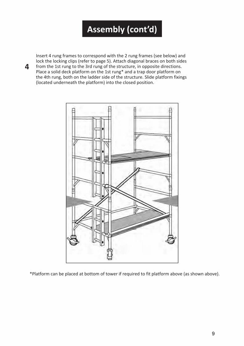
Insert 4 rung frames to correspond with the 2 rung frames (see below) and lock the locking clips (refer to page 5). Attach diagonal braces on both sides from the 1st rung to the 3rd rung of the structure, in opposite directions. Place a solid deck platform on the 1st rung* and a trap door platform on the 4th rung, both on the ladder side of the structure. Slide platform fixings (located underneath the platform) into the closed position.
*Platform can be placed at bottom of tower if required to fit platform above (as shown above).
4
9
Assembly (cont’d)
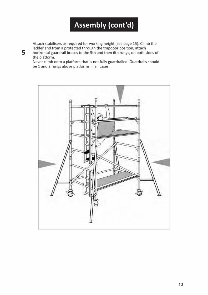
Attach stabilisers as required for working height (see page 15). Climb the ladder and from a protected through the trapdoor position, attach horizontal guardrail braces to the 5th and then 6th rungs, on both sides of the platform.Never climb onto a platform that is not fully guardrailed. Guardrails should be 1 and 2 rungs above platforms in all cases.
5
10
Assembly (cont’d)
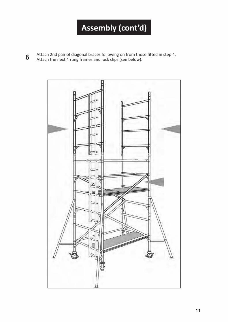
Attach 2nd pair of diagonal braces following on from those fitted in step 4.6 Attach the next 4 rung frames and lock clips (see below).
11

Assembly (cont’d)
If completing the tower at this height (4.2m platform height), continue with step 8. When building beyond this level, repeat steps 4, 5 and 6 until desired level is achieved, then complete the tower with steps 8 and 9.
7
12
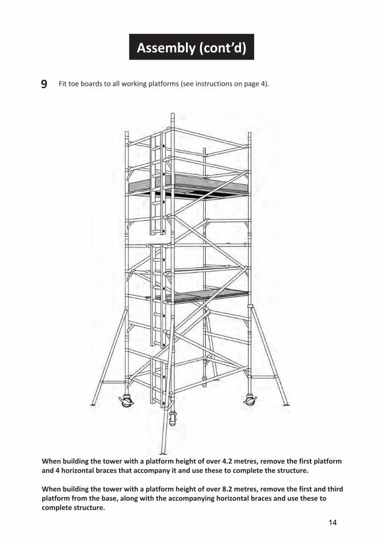
When building the tower with a platform height of over 4.2 metres, remove the first platform and 4 horizontal braces that accompany it and use these to complete the structure.
When building the tower with a platform height of over 8.2 metres, remove the first and third platform from the base, along with the accompanying horizontal braces and use these to complete structure.
Assembly (cont’d)
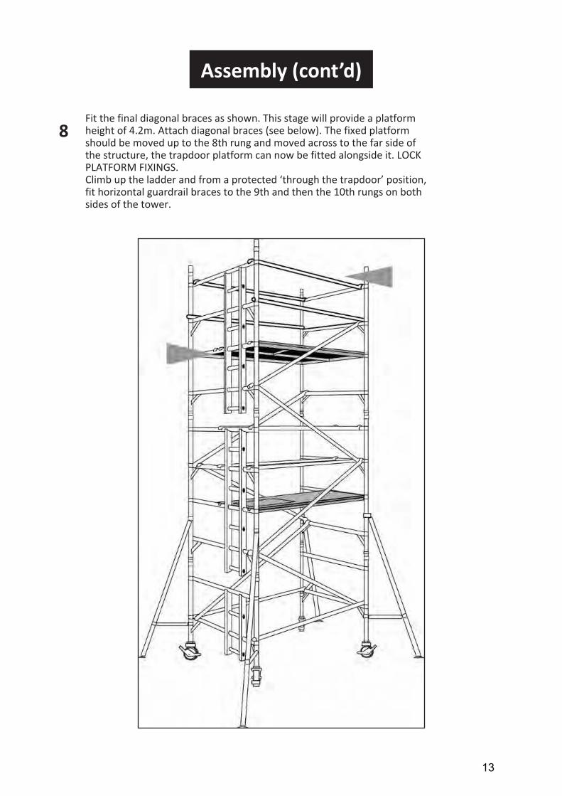
Fit the final diagonal braces as shown. This stage will provide a platform height of 4.2m. Attach diagonal braces (see below). The fixed platform should be moved up to the 8th rung and moved across to the far side of the structure, the trapdoor platform can now be fitted alongside it. LOCK PLATFORM FIXINGS.Climb up the ladder and from a protected ‘through the trapdoor’ position, fit horizontal guardrail braces to the 9th and then the 10th rungs on both sides of the tower.
8
13
Assembly (cont’d)
Fit toe boards to all working platforms (see instructions on page 4).9
14
When building the tower with a platform height of over 4.2 metres, remove the first platform and 4 horizontal braces that accompany it and use these to complete the structure.
When building the tower with a platform height of over 8.2 metres, remove the first and third platform from the base, along with the accompanying horizontal braces and use these to complete structure.
Dismantling
The dismantling procedure should follow the assembly steps in reverse order, take particular attention with regard to the removal of guardrails and platforms.
You should ensure that you are standing in a safe position and protected by guardrails at all times. NEVER remove diagonal braces or stabilisers prematurely.
After removing the toe-boards the operator disengages the horizontal guardrail brace clamps furthest from the trap door. Horizontal guardrail braces are then removed with the operator positioned through the trap door (3T) before descending to the lower level, from where the upper platform, diagonals and frames can be removed.
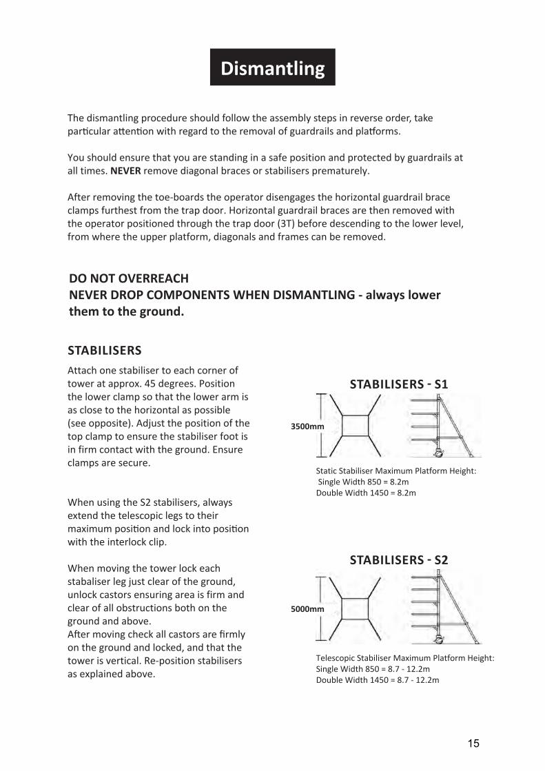
Attach one stabiliser to each corner of tower at approx. 45 degrees. Position the lower clamp so that the lower arm is as close to the horizontal as possible (see opposite). Adjust the position of the top clamp to ensure the stabiliser foot is in firm contact with the ground. Ensure clamps are secure.
When using the S2 stabilisers, alwaysextend the telescopic legs to their maximum position and lock into position with the interlock clip.
When moving the tower lock each stabaliser leg just clear of the ground, unlock castors ensuring area is firm and clear of all obstructions both on the ground and above.After moving check all castors are firmly on the ground and locked, and that the tower is vertical. Re-position stabilisers as explained above.
Static Stabiliser Maximum Platform Height: Single Width 850 = 8.2mDouble Width 1450 = 8.2m
Telescopic Stabiliser Maximum Platform Height:Single Width 850 = 8.7 - 12.2mDouble Width 1450 = 8.7 - 12.2m
DO NOT OVERREACH NEVER DROP COMPONENTS WHEN DISMANTLING - always lower them to the ground.
STABILISERS
STABILISERS - S1
STABILISERS - S2
3500mm
5000mm
15
Des
crip
tion
Wo
rkin
g H
eig
ht (M
)P
latf
orm
Hei
ght
4.2
2.2
4.7
2.7
5.2
3.2
5.7
3.7
6.2
4.2
6.7
4.7
7.2
5.2
7.7
5.7
8.2
6.2
8.7
6.7
9.2
7.2
9.7
7.7
10.2
8.2
44
44
44
44
44
44
4
44
44
44
44
44
44
4
11
11
11
1
11
11
11
1
11
11
11
11
11
11
11
21
22
32
33
43
4
11
21
22
32
33
43
4
12
22
22
22
3�
��
66
1010
1010
1010
1014
1�1�
1�
34
56
78
910
1112
1314
15
11
11
11
11
11
11
1
�������
�00�
���������
����
�������������
����1��0��2����������
���
����8�0��2����������
��
����8�0�������������
���
����8�0�������������
�
����
�8�0�������������
���
����8�0�������������
��
1�8�
����2
�����������
�����������
�
1800����2
�00���
�����
�����
�����
2100����2
�00�������
��������
Fold
ing ����������
44
44
44
44
S1
Sta
bili
ser
S2
Ad
just
able
Sta
bili
ser
Ap
pro
x To
wer
Sel
f-W
eigh
t (k
gs) 1
800
94.2
99.7
127
133
138
144
149.3
155
161
188
193
199
214.9
Ap
pro
x To
wer
Sel
f-W
eigh
t (k
gs) 2
500
104
110
144
151
157
163
169
175
181
215
221
228
244
10.7
8.7
11.2
9.2
11.7
9.7
12.2
10.2
12.7
10.7
13.2
11.2
13.7
11.7
14.2
12.2
44
44
44
44
44
44
44
44
11
11
11
11
11
11
45
45
56
56
45
45
56
56
��
��
��
��
1�1�
1�1�
1818
1818
1617
1819
2021
2223
11
11
11
44
44
44
44
220.4
226
232
237.6
264.5
270.1
276.1
281.6
250
256
262
268
303
309
315
321
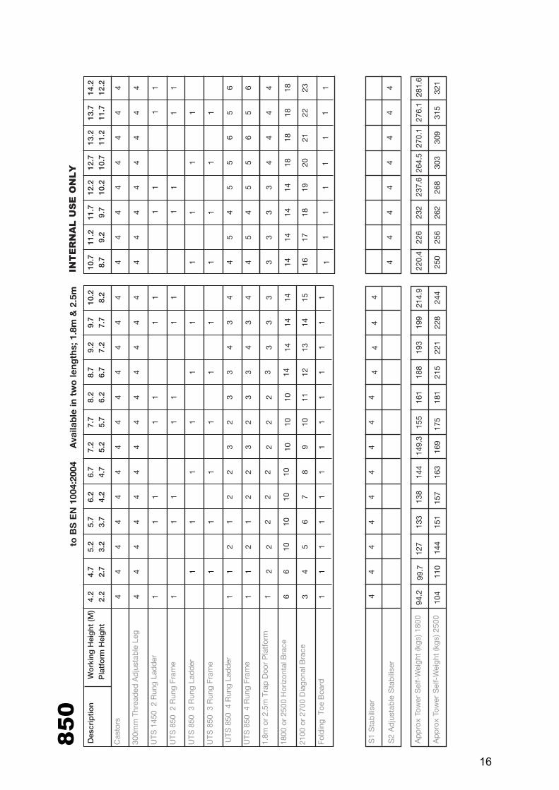
Quantity Scheduleto
BS
EN
100
4:20
04A
vaila
ble
in t
wo
leng
ths;
1.8
m &
2.5
m
15
44
44
INT
ER
NA
L U
SE
ON
LY
1 1
1 1 11
16
2
4
Des
crip
tion
Wo
rkin
g H
eig
ht (M
)P
latf
orm
Hei
ght
4.2
2.2
4.7
2.7
5.2
3.2
5.7
3.7
6.2
4.2
6.7
4.7
7.2
5.2
7.7
5.7
8.2
6.2
8.7
6.7
9.2
7.2
9.7
7.7
10.2
8.2
44
44
44
44
44
44
4
44
44
44
44
44
44
4
11
11
11
1
11
11
11
1
11
11
11
11
11
11
11
21
22
32
33
43
4
11
21
22
32
33
43
4
11
11
11
11
11
11
1
11
22
22
22
2�
��
�
66
1010
1010
1010
141�
1�1�
34
56
78
910
1112
1314
15
Cas
tors
300m
m T
hre
aded
Ad
just
able
Leg
����1��0� 2
Ru
ng
Lad
der
����1��0� 2
Ru
ng
Fra
me
����1��0� 3
Ru
ng
Lad
der
����1��0� 3
Ru
ng
Fra
me
����1��0� 4
Ru
ng
Lad
der
����1��0� 4
Ru
ng
Fra
me
1.8m
or
2.5m
Fix
ed P
latf
orm
1.8
m o
r 2.
5m T
rap
Doo
r P
latf
orm
1800
or
2500
Hor
izon
tal B
race
210
0 or
270
0 D
iago
nal B
race
Fold
ing
Toe
Boa
rd
S1
Sta
bili
ser
44
44
44
44
S2
Ad
just
able
Sta
bili
ser
44
44
Ap
pro
x To
wer
Sel
f-W
eigh
t (k
gs) 1
800
113
119
147
154
160
167
199
206
209
214
220
228
244
Ap
pro
x To
wer
Sel
f-W
eigh
t (k
gs) 2
500
128
135
169
177
184
191
197
205
212
247
253
261
278
10.7
8.7
11.2
9.2
11.7
9.7
12.2
10.2
12.7
10.7
13.2
11.2
13.7
11.7
14.2
12.2
44
44
44
44
44
44
44
44
11
11
11
11
11
11
45
45
56
56
45
45
56
56
11
11
11
11
��
��
��
��
1�1�
1�1�
1818
1818
1617
1819
2021
2223
11
11
11
11
44
44
44
44
250
256
264
270
298
304
311
317
285
291
300
306
341
347
355
362
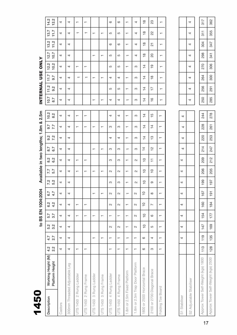
Quantity Schedule
to B
S E
N 1
004:
2004
Ava
ilab
le in
tw
o le
ngth
s; 1
.8m
& 2
.5m
INT
ER
NA
L U
SE
ON
LY
11
11
17
11
11
11
11
11
11
1
10