
141. Physical Medium Dependent (PMD) sublayer and...
24
Draft Amendment to IEEE Std 802.3-2015 IEEE Draft P802.3ca/D1.0 IEEE P802.3ca 100G-EPON PHY Task Force 12 March 2018 Copyright © 2018 IEEE. All rights reserved. This is an unapproved IEEE Standards draft, subject to change. 25 1 2 3 4 5 6 7 8 9 10 11 12 13 14 15 16 17 18 19 20 21 22 23 24 25 26 27 28 29 30 31 32 33 34 35 36 37 38 39 40 41 42 43 44 45 46 47 48 49 50 51 52 53 54 141. Physical Medium Dependent (PMD) sublayer and medium for 25G- EPON, 50G-EPON, and 100G-EPON passive optical networks 141.1 Overview Clause 141 describes Physical Medium dependent (PMD) sublayer for Ethernet Passive Optical Networks operating at the line rate of 25, 50, or 100 Gb/s, in either downstream or in both downstream and upstream directions. 141.1.1 Terminology and conventions EPONs operate over a point-to-multipoint (P2MP) topology, also called a tree or trunk-and-branch topol- ogy. The device connected at the root of the tree is called an Optical Line Terminal (OLT) and the devices connected as the leaves are referred to as Optical Network Units (ONUs). The direction of transmission from the OLT to the ONUs is referred to as the downstream direction, while the direction of transmission from the ONUs to the OLT is referred to as the upstream direction. 141.1.2 Power budget classes Clause 141 defines the following power budget classes: — Medium power budget class supports P2MP media channel insertion loss of ≤ 24 dB e.g., a PON with the split ratio of at least 1:16 and the distance of at least 20 km or a PON with the split ratio of at least 1:32 and the distance of at least 10 km. — High power budget class supports P2MP media channel insertion loss of ≤ 29 dB e.g., a PON with the split ratio of at least 1:32 and the distance of at least 20 km. 141.1.3 Power budgets Each power budget class is represented by PR-S-type power budget and PR-A-type power budget as follows: — PR-S power budget describes symmetric-rate PHY for PON operating at 25 Gb/s or 50 Gb/s, in both downstream and upstream directions, over a single SMF — PR-A power budget describes asymmetric-rate PHY for PON operating at 25 Gb/s or 50 Gb/s in the downstream direction and 10 Gb/s and above in the upstream direction, over a single SMF Each power budget is further identified with a numeric representation of its class, where a value of 20 represents the medium power budget and a value of 30 represents the high power budget. Thus, the following power budgets are defined in Clause 141: — PR-S20: symmetric-rate, medium power budget, — PR-S30: symmetric-rate, high power budget, — PR-A20: asymmetric-rate, medium power budget, — PR-A30: asymmetric-rate, high power budget.
Transcript of 141. Physical Medium Dependent (PMD) sublayer and...

Draft Amendment to IEEE Std 802.3-2015 IEEE Draft P802.3ca/D1.0IEEE P802.3ca 100G-EPON PHY Task Force 12 March 2018
1 2 3 4 5 6 7 8 9
10 11 12 13 14 15 16 17 18 19 20 21 22 23 24 25 26 27 28 29 30 31 32 33 34 35 36 37 38 39 40 41 42 43 44 45 46 47 48 49 50 51 52 53 54
141. Physical Medium Dependent (PMD) sublayer and medium for 25G-EPON, 50G-EPON, and 100G-EPON passive optical networks
141.1 Overview
Clause 141 describes Physical Medium dependent (PMD) sublayer for Ethernet Passive Optical Networks operating at the line rate of 25, 50, or 100 Gb/s, in either downstream or in both downstream and upstream directions.
141.1.1 Terminology and conventions
EPONs operate over a point-to-multipoint (P2MP) topology, also called a tree or trunk-and-branch topol-ogy. The device connected at the root of the tree is called an Optical Line Terminal (OLT) and the devices connected as the leaves are referred to as Optical Network Units (ONUs). The direction of transmission from the OLT to the ONUs is referred to as the downstream direction, while the direction of transmission from the ONUs to the OLT is referred to as the upstream direction.
141.1.2 Power budget classes
Clause 141 defines the following power budget classes:
— Medium power budget class supports P2MP media channel insertion loss of ≤ 24 dB e.g., a PON with the split ratio of at least 1:16 and the distance of at least 20 km or a PON with the split ratio of at least 1:32 and the distance of at least 10 km.
— High power budget class supports P2MP media channel insertion loss of ≤ 29 dB e.g., a PON with the split ratio of at least 1:32 and the distance of at least 20 km.
141.1.3 Power budgets
Each power budget class is represented by PR-S-type power budget and PR-A-type power budget as follows:
— PR-S power budget describes symmetric-rate PHY for PON operating at 25 Gb/s or 50 Gb/s, in both downstream and upstream directions, over a single SMF
— PR-A power budget describes asymmetric-rate PHY for PON operating at 25 Gb/s or 50 Gb/s in the downstream direction and 10 Gb/s and above in the upstream direction, over a single SMF
Each power budget is further identified with a numeric representation of its class, where a value of 20 represents the medium power budget and a value of 30 represents the high power budget. Thus, the following power budgets are defined in Clause 141:
— PR-S20: symmetric-rate, medium power budget,
— PR-S30: symmetric-rate, high power budget,
— PR-A20: asymmetric-rate, medium power budget,
— PR-A30: asymmetric-rate, high power budget.
Copyright © 2018 IEEE. All rights reserved.This is an unapproved IEEE Standards draft, subject to change.
25

Draft Amendment to IEEE Std 802.3-2015 IEEE Draft P802.3ca/D1.0IEEE P802.3ca 100G-EPON PHY Task Force 12 March 2018
1 2 3 4 5 6 7 8 9
10 11 12 13 14 15 16 17 18 19 20 21 22 23 24 25 26 27 28 29 30 31 32 33 34 35 36 37 38 39 40 41 42 43 44 45 46 47 48 49 50 51 52 53 54
Table 141–1 shows the primary attributes of all power budget types defined in Clause 141.
Table 141–1—Power budgets
Description
Medium Power Budget
High Power Budget Units
PR-S20 PR-A20 PR-S30 PR-A30
Number of fibers 1 –
Number of downstream wavelengths
1 or 2 –
Number of upstream wavelengths
1 or 2 1 1 or 2 1 –
Nominal downstreamline rate
25.78125 25.78125 25.78125 25.78125 GBd
Nominal upstream line rate
25.78125 10.3125 25.78125 10.3125 GBd
Nominal downstreamwavelength
1358±2 or 1342±2 nm
Nominal upstreamwavelength
1270±10 or 1300±10 <TBD>
1270±10 or 1300±10 <TBD> nm
Maximum reacha
aA compliant system may exceed the maximum reach designed for given power budget as long as optical power bud-get and other mandatory optical layer specifications are met.
20 km
Maximum channelinsertion loss
24 29 dB
Minimum channelinsertion loss
10 15 dB
Copyright © 2018 IEEE. All rights reserved.This is an unapproved IEEE Standards draft, subject to change.
26

Draft Amendment to IEEE Std 802.3-2015 IEEE Draft P802.3ca/D1.0IEEE P802.3ca 100G-EPON PHY Task Force 12 March 2018
1 2 3 4 5 6 7 8 9
10 11 12 13 14 15 16 17 18 19 20 21 22 23 24 25 26 27 28 29 30 31 32 33 34 35 36 37 38 39 40 41 42 43 44 45 46 47 48 49 50 51 52 53 54
141.1.4 Positioning of PMD sublayer within the IEEE 802.3 architecture
Figure 141–1 depicts the relationships of symmetric-rate (25G-EPON and 50G-EPON) and asymmetric-rate (25/10G-EPON, 50/25G-EPON, and 50/10G-EPON) PMD sublayer (shown hatched) with other sublayers and the ISO/IEC Open System Interconnection (OSI) reference model.
141.2 PMD types
The characteristics of the P2MP topology result in significantly different ONU and OLT PMDs. For example, the OLT PMD operates in a continuous mode in the transmit direction (downstream), but uses a burst mode in the receive direction (upstream). On the other hand, the ONU PMD receives data in a continuous mode, but transmits in a burst mode. To differentiate OLT PMDs from ONU PMDs, the OLT PMD name has a suffix “D” appended to it, where D stands for a downstream–facing PMD, whereas the ONU PMD has a suffix “U” appended to it, where U stands for an upstream-facing PMD.
Editorial NOTE (to be removed prior to publication): Figure 200-1 is a placeholder right now, to be replaced with updated drawing once complete architecture is available.
In the downstream direction, the signal transmitted by the D-type PMD is received by all U-type PMDs. In the upstream direction, the D-type PMD receives data bursts from each of the U-type PMDs.
Clause 141 defines several D-type and several U-type PMDs, that differ in their receive and/or transmit characteristics. Such PMDs are further distinguished by appending a digit after the suffix D or U.
The following OLT PMDs (D-type) are defined in this subclause:
a) Asymmetric-rate D-type PMDs (collectively referred to as PR-S-D), transmitting at 25 Gb/s (or more) continuous mode and receiving at 25 Gb/s (or more) burst mode:
1) {PMD-S-D} typesb) Symmetric-rate D-type PMDs (collectively referred to as {PR-A-D}), transmitting at {TBD} GBd
continuous mode and receiving at {TBD} GBd burst mode:
1) {PMD-A-D} types
The following ONU PMDs (U-type) are defined in this subclause:
a) Asymmetric-rate U-type PMDs (collectively referred to as 10/1GBASE–PRX–U), transmitting at 1.25 GBd burst mode and receiving at 10.3125 GBd continuous mode:1) {PMD_Y_D} types
b) Symmetric-rate U-type PMDs (collectively referred to as 10GBASE–PR–U), transmitting at 10.3125 GBd burst mode and receiving at 10.3125 GBd continuous mode:
1) {PMD_X_D} types
Editorial Note (to be removed prior to publication): Need a scrub of the draft to remove all references to 1.25 GBd PHYs, 1G-EPON, and use proper PMD names
A specific power budget is achieved by combining an OLT PMD (D-type) with an ONU PMD (U-type) as shown in 141.2.1. Detailed PMD receive and transmit characteristics for D-type PMDs are given in 141.5 and characteristics for U-type PMDs are presented in 141.6. Every PMD has non-overlapping transmit and receive wavelength bands and operates over a single SMF (see {TBD future ANNEX}).
Copyright © 2018 IEEE. All rights reserved.This is an unapproved IEEE Standards draft, subject to change.
27

Draft Amendment to IEEE Std 802.3-2015 IEEE Draft P802.3ca/D1.0IEEE P802.3ca 100G-EPON PHY Task Force 12 March 2018
1 2 3 4 5 6 7 8 9
10 11 12 13 14 15 16 17 18 19 20 21 22 23 24 25 26 27 28 29 30 31 32 33 34 35 36 37 38 39 40 41 42 43 44 45 46 47 48 49 50 51 52 53 54
PMA
PCSFEC
PMA (Clause 142)
PMD (Clause 141)
PCS (Clause 142)FEC (Clause 142)
MDI
Figure 141–1—Relationship of EPON P2MP PMD to the ISO/IEC OSI reference model and the IEEE 802.3 Ethernet model
25GMII=25 GIGABIT MEDIA INDEPENDENT INTERFACEMDI = MEDIUM DEPENDENT INTERFACEOAM = OPERATIONS, ADMINISTRATION & MAINTENANCEOLT = OPTICAL LINE TERMINALMPRS= MULTI-POINT RECONCILIATION SUBLAYERMPCP= MULTI-POINT CONTROL PROTOCOL
ONU = OPTICAL NETWORK UNITPCS = PHYSICAL CODING SUBLAYERPHY = PHYSICAL LAYER DEVICEPMA = PHYSICAL MEDIUM ATTACHMENTPMD = PHYSICAL MEDIUM DEPENDENT
APPLICATION
PRESENTATION
SESSION
TRANSPORT
NETWORK
DATA LINK
PHYSICAL
OSIREFERENCE
MODELLAYERS
ETHERNETLAYERS
OLT Control Plane
MAC CLIENT
OAM (Optional)
MPCP (Clause 144)
MPRS (Clause 143)
PHY
APPLICATION
PRESENTATION
SESSION
TRANSPORT
NETWORK
DATA LINK
PHYSICAL
OSIREFERENCE
MODELLAYERS
Opticaldistributor
combiner(s)
Fiber
PON Medium
Fib
er
Fib
er
OLT
ONU
PMD and MDI described in this clause
MAC
MAC CLIENT
OAM (Optional)
MAC
MAC CLIENT
MAC
MAC CLIENT
MAC
ETHERNETLAYERS
OLT Data Plane
MDI
MPRS (Clause 143)
ETHERNETLAYERS
ONU Control Plane
MAC CLIENT
OAM (Optional)
MPCP (Clause 144)
MAC
MAC CLIENT
MAC
MAC CLIENT
MAC
ETHERNETLAYERS
ONU Data Plane
Fiber
25G
MII
25G
MII
PMA
PCSFEC
PMA (Clause 142)
PMD (Clause 141)
PCS (Clause 142)FEC (Clause 142)
PHY
25G
MII
25G
MII
Copyright © 2018 IEEE. All rights reserved.This is an unapproved IEEE Standards draft, subject to change.
28

Draft Amendment to IEEE Std 802.3-2015 IEEE Draft P802.3ca/D1.0IEEE P802.3ca 100G-EPON PHY Task Force 12 March 2018
1 2 3 4 5 6 7 8 9
10 11 12 13 14 15 16 17 18 19 20 21 22 23 24 25 26 27 28 29 30 31 32 33 34 35 36 37 38 39 40 41 42 43 44 45 46 47 48 49 50 51 52 53 54
141.2.1 Mapping of PMDs to power budgets
The power budget is determined by the PMDs located at the ends of the physical media. This subclause describes how PMDs may be combined to achieve the power budgets listed in Table 141–1.
141.2.1.1 Symmetric-rate, {PMD_X} power budgets ({NG} type)
Table 141–2 illustrates recommended pairings of symmetric-rate ONU PMDs with symmetric-rate OLT PMDs to achieve the power budgets as shown in Table 141–1.
141.2.1.2 Asymmetric-rate, {PMD_Y} power budgets ({NG} type)
Table 141–3 illustrates recommended pairings of asymmetric-rate ONU PMDs with asymmetric-rate OLT PMDs to achieve the power budgets as shown in Table 141–1.
141.3 PMD functional specifications
The {NG-EPON type} PMDs perform the transmit and receive functions that convey data between the PMD service interface and the MDI.
141.3.1 PMD service interface
The following specifies the services provided by Clause 141 PMDs. These PMD sublayer service interfaces are described in an abstract manner and do not imply any particular implementation.
Table 141–2—PMD – power budget mapping for symmetric-rate {NG}–type power budgets
OLT PMDs
ON
U P
MD
s
Table 141–3—PMD – power budget mapping for asymmetric-rate {NG}–type power budgets
OLT PMDs
ON
U P
MD
s
Copyright © 2018 IEEE. All rights reserved.This is an unapproved IEEE Standards draft, subject to change.
29

Draft Amendment to IEEE Std 802.3-2015 IEEE Draft P802.3ca/D1.0IEEE P802.3ca 100G-EPON PHY Task Force 12 March 2018
1 2 3 4 5 6 7 8 9
10 11 12 13 14 15 16 17 18 19 20 21 22 23 24 25 26 27 28 29 30 31 32 33 34 35 36 37 38 39 40 41 42 43 44 45 46 47 48 49 50 51 52 53 54
The PMD Service Interface supports the exchange of a continuous stream of bits, representing 256B/257B blocks, between the PMA and PMD entities. The PMD translates the serialized data received from the compatible PMA to and from signals suitable for the specified medium. The following primitives are defined:
— PMD_UNITDATA.request— PMD_UNITDATA.indication— PMD_SIGNAL.request— PMD_SIGNAL.indication
141.3.1.1 Delay constraints
{TBD}
141.3.1.2 PMD_UNITDATA.request
This primitive defines the transfer of a serial data stream from the Clause 201 PMA to the PMD.
{TBD, depending on the structure of PMA}
141.3.1.3 PMD_UNITDATA.indication
This primitive defines the transfer of data from the PMD to the Clause 201 PMA.
{TBD, depending on the structure of PMA}
141.3.1.4 PMD_SIGNAL.request
{TBD, depending on the structure of PMA}
141.3.1.5 PMD_SIGNAL.indication
{TBD, depending on the structure of PMA}
141.3.2 PMD block diagram
The PMD sublayer is defined at the eight reference points shown in Figure 141–2 for 100G-EPON PMDs.
For 100G-EPON PMDs, test points TP1 through TP4 refer to the downstream channel, while test points TP5 through TP8 refer to the upstream channel. In the downstream channel, TP2 and TP3 are compliance points, while in the upstream channel TP6 and TP7 are compliance points. TP1, TP4, TP5, and TP8 are reference points for use by implementers. The optical transmit signal is defined at the output end of a patch cord (TP2 for the downstream channel and TP6 for the upstream channel), between 2 m and 5 m in length, of a fiber type consistent with the link type connected to the transmitter. Unless specified otherwise, all transmitter measurements and tests defined in 141.8 are made at TP2 or TP6. The optical receive signal is defined at the output of the fiber optic cabling (TP3 for the downstream channel and TP7 for the upstream channel) connected to the receiver. Unless specified otherwise, all receiver measurements and tests defined in 141.8 are made at TP3 or TP7.
The electrical specifications of the PMD service interface (TP1 and TP4 for the downstream channel and TP5 and TP8 for the upstream channel) are not system compliance points (these are not readily testable in a system implementation).
Copyright © 2018 IEEE. All rights reserved.This is an unapproved IEEE Standards draft, subject to change.
30

Draft Amendment to IEEE Std 802.3-2015 IEEE Draft P802.3ca/D1.0IEEE P802.3ca 100G-EPON PHY Task Force 12 March 2018
1 2 3 4 5 6 7 8 9
10 11 12 13 14 15 16 17 18 19 20 21 22 23 24 25 26 27 28 29 30 31 32 33 34 35 36 37 38 39 40 41 42 43 44 45 46 47 48 49 50 51 52 53 54
141.3.3 PMD transmit function
{TBD, depending on the structure of PMA}
141.3.4 PMD receive function
{TBD, depending on the structure of PMA}
141.3.5 PMD signal detect function
141.3.5.1 ONU PMD signal detect
{TBD, depending on the structure of PMA}
141.3.5.2 OLT PMD signal detect
The response time for the PMD Signal Detect function for the burst mode upstream signal may be longer or shorter than a burst length; thus, it may not fulfill the traditional requirements placed on Signal Detect. PMD_SIGNAL.indication is intended to be an indicator of optical signal presence. The signal detect function in the OLT may be realized in the PMD or the Clause 142 PMA sublayer.
OLT
PMD
ONU
PMD #1
Optical
splitter
Fiber optic cabling
MDI
ONUPMD #n
PMA
PatchCord
PMA
System bulkheads
and passive optical splitter(Channel)
Figure 141–2—10GBASE–PR and 10/1GBASE–PRX block diagram
Tx_Enable
TP6
MDI
SMF cable
SMF cable
SMF cable
Unterminatedsplit
SMF cable
PMA
TP5
TP7
TP8
ONU
PMD #2 PMA
SMF cable
TP1
TP2
TP3TP4
SIGNAL_DETECT
SIGNAL_DETECT
Editorial Note: to be updat-ed once decision on refer-ence points is made
Copyright © 2018 IEEE. All rights reserved.This is an unapproved IEEE Standards draft, subject to change.
31

Draft Amendment to IEEE Std 802.3-2015 IEEE Draft P802.3ca/D1.0IEEE P802.3ca 100G-EPON PHY Task Force 12 March 2018
1 2 3 4 5 6 7 8 9
10 11 12 13 14 15 16 17 18 19 20 21 22 23 24 25 26 27 28 29 30 31 32 33 34 35 36 37 38 39 40 41 42 43 44 45 46 47 48 49 50 51 52 53 54
The value of the SIGNAL_DETECT parameter shall be generated according to the conditions defined in Table 141–4 for PMDs defined in Clause 141. The 100G-EPON PMD receiver is not required to verify whether a compliant 100G-EPON signal is being received.
141.3.5.3 100G-EPON Signal detect functions
The Signal Detect value definitions for Clause 141 PMDs are shown in Table 141–4.
141.3.6 PMD transmit enable function for ONU
PMD_SIGNAL.request(tx_enable) is defined for all ONU PMDs specified in Clause 141. PMD_SIGNAL.request(tx_enable) is asserted prior to data transmission by the ONU PMDs.
141.4 Wavelength channel allocation
Downstream channel wavelength assignments are defined in Table 141–5.
Upstream channel wavelength assignments are defined in Table 141–6.
141.5 PMD to MDI optical specifications for 25G-EPON and 50G-EPON OLT PMDs
Table 141–4—SIGNAL_DETECT value definitions for Clause 141 PMDs
PMD type Receive conditions SIGNAL_DETECTvalue
100G-EPON PMD
Average input optical power Signal Detect Threshold (min) in Table {TBD} at the specified receiver wavelength FAIL
Average input optical power Receive sensitivity (max) in Table {TBD} with a compliant signal input at the specified receiver wavelength
OK
All other conditions Unspecified
Table 141–5—Downstream channel wavelength assignments
Channel Name
Center frequency(THz)
Center wavelength(nm)
Wavelength range(nm)
DW0 TBD 1358 ±2
DW1 TBD 1342 ±2
Table 141–6—Upstream channel wavelength assignments
Wavelength Name
Center frequency(THz)
Center wavelength(nm)
Wavelength range(nm)
UW0 TBD 1270 ±10
UW1 TBD 1300 ±10
UW2 TBD 1320 ±2
Copyright © 2018 IEEE. All rights reserved.This is an unapproved IEEE Standards draft, subject to change.
32

Draft Amendment to IEEE Std 802.3-2015 IEEE Draft P802.3ca/D1.0IEEE P802.3ca 100G-EPON PHY Task Force 12 March 2018
1 2 3 4 5 6 7 8 9
10 11 12 13 14 15 16 17 18 19 20 21 22 23 24 25 26 27 28 29 30 31 32 33 34 35 36 37 38 39 40 41 42 43 44 45 46 47 48 49 50 51 52 53 54
This subclause details the PMD to MDI optical specifications for 25G-EPON and 50G-EPON OLT PMDs, as specified in 141.2. Specifically, 141.5.1 defines the OLT transmit parameters, while 141.5.2 defines the OLT receive parameters.
The operating ranges for {XXX} power budget classes are defined in Table 141–1. A {XXX} compliant transceiver operates over the media types listed in Table 141–15 according to the specifications described in 141.10. A transceiver which exceeds the operational range requirement while meeting all other optical specifications is considered compliant.
NOTE—The specifications for OMA have been derived from extinction ratio and average launch power (minimum) or receiver sensitivity (maximum). The calculation is defined in 58.7.6.
141.5.1 Transmitter optical specifications
Table 141–7—OLT PR20 Transmit Characteristics
Parameter 25GBASE-PR20-D 50GBASE-PR20-D50/25GBASE-PR20-D Unit
Channel wavelength rangesDW0 1358 ± 2 1358 ± 2 nm
DW1 N/A 1342 ± 2 nm
Signaling rate, (range) 25.78125 ± 100 ppm GBd
Side-mode suppression ratio (SMSR), (min) dB
Total average launch power (max) dBm
Average launch power, each channel (max) dBm
Average launch power, each channela (min)
a Average launch power, each channel (min) is informative and not the principal indicator of signal strength. A trans-mitter with launch power below this value cannot be compliant; however, a value above this does not ensure compli-ance.
dBm
Optical Modulation Amplitude (OMA), each channel (max) dBm
Optical Modulation Amplitude (OMA), each channel (min) b
b Even if the TDP < TBD dB, the OMA (min) must exceed this value.
dBm
Difference in launch power between any two channels (OMA) (max)
dB
Launch power in OMA minus TDP, each channel (min) dBm
Transmitter and dispersion penalty (TDP), each channel (max) dB
Average launch power of OFF transmitter, each channel (max) dBm
Extinction ratio (min) dB
RIN15OMA (max) dB/Hz
Optical return loss tolerance (max) dB
Transmitter reflectancec (max)
c Transmitter reflectance is defined looking into the transmitter.
dB
Transmitter eye mask definition {X1, X2, X3, Y1, Y2, Y3}
UI
Decision timing offset for transmitter and dispersion penalty UI
Copyright © 2018 IEEE. All rights reserved.This is an unapproved IEEE Standards draft, subject to change.
33

Draft Amendment to IEEE Std 802.3-2015 IEEE Draft P802.3ca/D1.0IEEE P802.3ca 100G-EPON PHY Task Force 12 March 2018
1 2 3 4 5 6 7 8 9
10 11 12 13 14 15 16 17 18 19 20 21 22 23 24 25 26 27 28 29 30 31 32 33 34 35 36 37 38 39 40 41 42 43 44 45 46 47 48 49 50 51 52 53 54
{TBD}
141.5.2 Receiver optical specifications
141.6 PMD to MDI optical specifications for 25G-EPON and 50G-EPON ONU PMDs
This subclause details the PMD to MDI optical specifications for 25G-EPON and 50G-EPON ONU PMDs, as specified in 141.2. Specifically, 141.6.1 defines the ONU transmit parameters, while 141.6.2 defines the ONU receive parameters.
Table 141–8—OLT PR30 Transmit Characteristics
Parameter 25GBASE-PR30-D 50GBASE-PR30-D50/25GBASE-PR30-D Unit
Channel wavelength rangesDW0 1358 ± 2 1358 ± 2 nm
DW1 N/A 1342 ± 2 nm
Signaling rate, each channel (range) 25.78125 ± 100 ppm GBd
Side-mode suppression ratio (SMSR), (min) dB
Total average launch power (max) dBm
Average launch power, each channel (max) 4.8 dBm
Average launch power, each channela (min) dBm
Optical Modulation Amplitude (OMA), each channel (max) dBm
Optical Modulation Amplitude (OMA), each channel (min) b dBm
Difference in launch power between any two channels (OMA) (max)
dB
Launch power in OMA minus TDP, each channel (min) dBm
Transmitter and dispersion penalty (TDP), each channel (max) dB
Average launch power of OFF transmitter, each channel (max) dBm
Extinction ratio (min) 8 dB
RIN15OMA (max) dB/Hz
Optical return loss tolerance (max) dB
Transmitter reflectancec (max) dB
Transmitter eye mask definition {X1, X2, X3, Y1, Y2, Y3} UI
Decision timing offset for transmitter and dispersion penalty UI
a Average launch power, each channel (min) is informative and not the principal indicator of signal strength. A trans-mitter with launch power below this value cannot be compliant; however, a value above this does not ensure compli-ance.
b Even if the TDP < TBD dB, the OMA (min) must exceed this value. c Transmitter reflectance is defined looking into the transmitter.
Copyright © 2018 IEEE. All rights reserved.This is an unapproved IEEE Standards draft, subject to change.
34

Draft Amendment to IEEE Std 802.3-2015 IEEE Draft P802.3ca/D1.0IEEE P802.3ca 100G-EPON PHY Task Force 12 March 2018
1 2 3 4 5 6 7 8 9
10 11 12 13 14 15 16 17 18 19 20 21 22 23 24 25 26 27 28 29 30 31 32 33 34 35 36 37 38 39 40 41 42 43 44 45 46 47 48 49 50 51 52 53 54
The operating ranges for {XXX} power budget classes are defined in Table 141–1. A {XXX} compliant transceiver operates over the media types listed in Table 141–15 according to the specifications described in 141.10. A transceiver which exceeds the operational range requirement while meeting all other optical specifications is considered compliant.
NOTE—The specifications for OMA have been derived from extinction ratio and average launch power (minimum) or receiver sensitivity (maximum). The calculation is defined in 58.7.6.
Table 141–9—OLT PR20 Receive Characteristics
Parameter 25GBASE-PR20-D50/25GBASE-PR20-D
50GBASE-PR20-D 25/10GBASE-PR20-D50/10GBASE-PR20-D Unit
Channel wavelength ranges
UW0 TBD.UC0range TBD.UC0range 1270 ± 10 nm
UW1 TBD.UC1range 1300 ± 10 nm
UW2 nm
Signaling rate, each channel (range) 25.78125 ± 100 ppm See Table 75-6 GBd
Bit error ratio (max)a 10-2
Damage Thresholdb
See Table 75-6
dBm
Average receive power, each chan-nel (max) dBm
Average receive power, each chan-nelc (min) dBm
Receive power, each channel (OMA) (max) dBm
Receiver reflectance (max) dB
Receiver sensitivity (OMA), each
channeld (max)dBm
Signal detect threshold, each chan-nel (min) GHz
Stressed receiver sensitivity (OMA), each channele (max) dBm
Receiver settling time (max) ns
Conditions of stressed receiver sen-sitivity test:
Vertical eye closure penalty,f each channel dB
Stressed eye J2 Jitter,e each channel UI
Stressed eye J9 Jitter,e each channel UI
a The BER of 10–TBD is achieved by the utilization of FEC as described in XX.X.b The receiver shall be able to tolerate, without damage, continuous exposure to an optical input signal having this av-erage power level.
c Average receive power, each channel (min) is informative and not the principal indicator of signal strength. A re-ceived power below this value cannot be compliant; however, a value above this does not ensure compliance.
d Receiver sensitivity (OMA), each channel (max) is informative.e Measured with conformance test signal at TP7 (see xx.xx.xx.xx) for BER = 10–TBD.f Vertical eye closure penalty, stressed eye J2 Jitter, and stressed eye J9 Jitter are test conditions for measuring stressedreceiver sensitivity. They are not characteristics of the receiver.
Copyright © 2018 IEEE. All rights reserved.This is an unapproved IEEE Standards draft, subject to change.
35

Draft Amendment to IEEE Std 802.3-2015 IEEE Draft P802.3ca/D1.0IEEE P802.3ca 100G-EPON PHY Task Force 12 March 2018
1 2 3 4 5 6 7 8 9
10 11 12 13 14 15 16 17 18 19 20 21 22 23 24 25 26 27 28 29 30 31 32 33 34 35 36 37 38 39 40 41 42 43 44 45 46 47 48 49 50 51 52 53 54
141.6.1 Transmitter optical specifications
Table 141–10—OLT PR30 Receive Characteristics
Parameter 25GBASE-PR30-D50/25GBASE-PR30-D
50GBASE-PR30-D 25/10GBASE-PR30-D50/10GBASE-PR30-D Unit
Channel wavelength ranges
UW0 TBD.UC0range TBD.UC0range 1270 ± 10 nm
UW1 TBD.UC1range 1300 ± 10 nm
UW2 nm
Signaling rate, each channel (range) 25.78125 ± 100 ppm See Table 75-6 GBd
Bit error ratio (max)a 10-2
Damage Thresholdb
See Table 75-6
dBm
Average receive power, each chan-nel (max) dBm
Average receive power, each chan-nelc (min) dBm
Receive power, each channel (OMA) (max) dBm
Receiver reflectance (max) dB
Receiver sensitivity (OMA), each
channeld (max)-25.0 dBm
Signal detect threshold, each chan-nel (min)
GHz
Stressed receiver sensitivity (OMA), each channele (max)
dBm
Receiver settling time (max) ns
Conditions of stressed receiver sen-sitivity test:
Vertical eye closure penalty,f each channel dB
Stressed eye J2 Jitter,e each channel UI
Stressed eye J9 Jitter,e each channel UI
a The BER of 10–TBD is achieved by the utilization of FEC as described in XX.X.b The receiver shall be able to tolerate, without damage, continuous exposure to an optical input signal having this average power level.
c Average receive power, each channel (min) is informative and not the principal indicator of signal strength. A re-ceived power below this value cannot be compliant; however, a value above this does not ensure compliance.
d Receiver sensitivity (OMA), each channel (max) is informative.e Measured with conformance test signal at TP7 (see xx.xx.xx.xx) for BER = 10–TBD.f Vertical eye closure penalty, stressed eye J2 Jitter, and stressed eye J9 Jitter are test conditions for measuring stressed receiver sensitivity. They are not characteristics of the receiver.
Copyright © 2018 IEEE. All rights reserved.This is an unapproved IEEE Standards draft, subject to change.
36

Draft Amendment to IEEE Std 802.3-2015 IEEE Draft P802.3ca/D1.0IEEE P802.3ca 100G-EPON PHY Task Force 12 March 2018
1 2 3 4 5 6 7 8 9
10 11 12 13 14 15 16 17 18 19 20 21 22 23 24 25 26 27 28 29 30 31 32 33 34 35 36 37 38 39 40 41 42 43 44 45 46 47 48 49 50 51 52 53 54
Table 141–11—ONU PR20 Transmit Characteristics
Parameter 25GBASE-PR20-U50/25GBASE-PR20-U
50GBASE-PR20-U 25/10GBASE-PR20-U50/10GBASE-PR20-U Unit
Channel wavelength ranges
UW0 TBD.UC0range TBD.UC0range 1270 ± 10 nm
UW1 TBD.UC1range 1300 ± 10 nm
UW2 nm
Signaling rate, each channel (range) 25.78125 ± 100 ppm
See Table 75-8
GBd
Side-mode suppression ratio (SMSR), (min) dB
Total average launch power (max) dBm
Average launch power, each channel (max) dBm
Average launch power, each chan-nela (min) dBm
Optical Modulation Amplitude (OMA), each channel (max)
dBm
Optical Modulation Amplitude (OMA), each channel (min)b dBm
Difference in launch power between any two channels (OMA) (max)
dB
Launch power in OMA minus TDP, each channel (min) dBm
Transmitter and dispersion penalty (TDP), each channel (max) dB
Average launch power of OFF trans-mitter, each channel (max) dBm
Extinction ratio (min) dB
RIN15OMA (max) dB/Hz
Optical return loss tolerance (max) dB
Transmitter reflectancec (max) dB
Transmitter eye mask definition {X1, X2, X3, Y1, Y2, Y3} UI
Turn-on time (max) ns
Turn-off time (max) ns
Decision timing offset for transmit-ter and dispersion penalty UI
a Average launch power, each channel (min) is informative and not the principal indicator of signal strength. A trans-mitter with launch power below this value cannot be compliant; however, a value above this does not ensure compli-ance.
b Even if the TDP < TBD dB, the OMA (min) must exceed this value.c Transmitter reflectance is defined looking into the transmitter.
Copyright © 2018 IEEE. All rights reserved.This is an unapproved IEEE Standards draft, subject to change.
37

Draft Amendment to IEEE Std 802.3-2015 IEEE Draft P802.3ca/D1.0IEEE P802.3ca 100G-EPON PHY Task Force 12 March 2018
1 2 3 4 5 6 7 8 9
10 11 12 13 14 15 16 17 18 19 20 21 22 23 24 25 26 27 28 29 30 31 32 33 34 35 36 37 38 39 40 41 42 43 44 45 46 47 48 49 50 51 52 53 54
Table 141–12—ONU PR30 Transmit Characteristics
Parameter 25GBASE-PR30-U50/25GBASE-PR30-U
50GBASE-PR30-U 25/10GBASE-PR30-U50/10GBASE-PR30-U Unit
Channel wavelength ranges
UW0 TBD.UC0range TBD.UC0range 1270 ± 10 nm
UW1 TBD.UC1range 1300 ± 10 nm
UW2 nm
Signaling rate, each channel (range) 25.78125 ± 100 ppm
See Table 75-8
GBd
Side-mode suppression ratio (SMSR), (min)
dB
Total average launch power (max) dBm
Average launch power, each chan-nel (max) dBm
Average launch power, each chan-nela (min) dBm
Optical Modulation Amplitude (OMA), each channel (max) dBm
Optical Modulation Amplitude (OMA), each channel (min)b dBm
Difference in launch power between any two channels (OMA) (max)
dB
Launch power in OMA minus TDP, each channel (min) dBm
Transmitter and dispersion penalty (TDP), each channel (max)
4Editorial Note (to be removed prior to publica-
tion): Motion #7 from 2018/03 states “25G ONU transmitter: ERmin = 5 dB, (AVP minus
TDP)min = 4.0dBm and update the draft” but there is no AVP minus TDP entry in tables.
dB
Average launch power of OFF transmitter, each channel (max) dBm
Extinction ratio (min) 5 dB
RIN15OMA (max) dB/Hz
Optical return loss tolerance (max) dB
Transmitter reflectancec (max) dB
Transmitter eye mask definition {X1, X2, X3, Y1, Y2, Y3}
UI
Turn-on time (max) ns
Turn-off time (max) ns
Decision timing offset for transmit-ter and dispersion penalty UI
a Average launch power, each channel (min) is informative and not the principal indicator of signal strength. A trans-mitter with launch power below this value cannot be compliant; however, a value above this does not ensure compli-ance.
b Even if the TDP < TBD dB, the OMA (min) must exceed this value.c Transmitter reflectance is defined looking into the transmitter.
Copyright © 2018 IEEE. All rights reserved.This is an unapproved IEEE Standards draft, subject to change.
38

Draft Amendment to IEEE Std 802.3-2015 IEEE Draft P802.3ca/D1.0IEEE P802.3ca 100G-EPON PHY Task Force 12 March 2018
1 2 3 4 5 6 7 8 9
10 11 12 13 14 15 16 17 18 19 20 21 22 23 24 25 26 27 28 29 30 31 32 33 34 35 36 37 38 39 40 41 42 43 44 45 46 47 48 49 50 51 52 53 54
141.6.2 Receiver optical specifications
The signaling speed, operating wavelength, overload, stressed sensitivity, reflectance, and signal detect for receivers forming part of the {PMD-types} ONU PMDs (as specified in 141.2) shall meet the specifications defined in Table 141–5 for Clause 141 ONU PMDs, per measurement techniques defined in 141.7. Their unstressed receive characteristics should meet the values listed in Table 141–5 per measurement techniques described in 141.7.11. Either the damage threshold included in Table 141–5 shall be met, or the receiver shall be labeled to indicate the maximum optical input power level to which it can be continuously exposed without damage.
The damage threshold included in Table 141–5 does not guarantee direct ONU–OLT connection, which may result in damage of the receiver. If direct ONU–OLT connection is necessary, optical attenuators and/or equivalent loss components should be inserted to decrease receive power below damage threshold.
Table 141–13—ONU PR20 Receive Characteristics
Parameter 25GBASE-PR20-U 50GBASE-PR20-U50/25GBASE-PR20-U Unit
Channel wavelength rangesDW0 1358 ± 2 1358 ± 2 nm
DW1 N/A 1342 ± 2 nm
Signaling rate, each channel (range) 25.78125 ± 100 ppm GBd
Bit error ratio (max) a
a The BER of 10–TBD is achieved by the utilization of FEC as described in xx.xx.xx.xx.
10-2
Damage Thresholdb
b The receiver shall be able to tolerate, without damage, continuous exposure to an optical input signal having this average power level.
dBm
Average receive power, each channel (max) dBm
Average receive power, each channelc (min)
c Average receive power, each channel (min) is informative and not the principal indicator of signal strength. A re-ceived power below this value cannot be compliant; however, a value above this does not ensure compliance.
dBm
Receive power, each channel (OMA) (max) dBm
Receiver reflectance (max) dB
Receiver sensitivity (OMA), each channeld (max)
d Receiver sensitivity (OMA), each channel (max) is informative.
dBm
Detect threshold, each channel (min) dBm
Stressed receiver sensitivity (OMA), each channele (max)
e Measured with conformance test signal at TP3 (see xx.xx.xx.xx) for BER = 10–TBD.
dBm
Conditions of stressed receiver sensitivity test
Vertical eye closure penalty,f each channel
f Vertical eye closure penalty, stressed eye J2 Jitter, and stressed eye J9 Jitter are test conditions for measuring stressedreceiver sensitivity. They are not characteristics of the receiver.
dB
Stressed eye J2 Jitter,e each channel UI
Stressed eye J9 Jitter,e each channel UI
Copyright © 2018 IEEE. All rights reserved.This is an unapproved IEEE Standards draft, subject to change.
39

Draft Amendment to IEEE Std 802.3-2015 IEEE Draft P802.3ca/D1.0IEEE P802.3ca 100G-EPON PHY Task Force 12 March 2018
1 2 3 4 5 6 7 8 9
10 11 12 13 14 15 16 17 18 19 20 21 22 23 24 25 26 27 28 29 30 31 32 33 34 35 36 37 38 39 40 41 42 43 44 45 46 47 48 49 50 51 52 53 54
141.7 Definitions of optical parameters and measurement methods
When measuring jitter at TP1 and TP5, it is recommended that jitter contributions at frequencies below receiver corner frequencies (i.e., {TBD}) are filtered at the measurement unit. The following subclauses describe definitive patterns and test procedures for Clause 141 PMDs. Implementers using alternative verification methods should ensure adequate correlation and allow adequate margin such that specifications are met by reference to the definitive methods. All optical measurements, except TDP and RIN15OMA shall be made through a short patch cable between 2 m and 5 m in length.
141.7.1 Insertion loss
Insertion loss for SMF fiber optic cabling (channel) is defined at {TBD, NG-EPON wavelengths}, depending on the particular PMD. A suitable test method is described in ITU–T G.650.1.
Table 141–14—ONU PR30 Receive Characteristics
Parameter 25GBASE-PR30-U 50GBASE-PR30-U50/25GBASE-PR30-U Unit
Channel wavelength rangesDW0 1358 ± 2 1358 ± 2 nm
DW1 N/A 1342 ± 2 nm
Signaling rate, each channel (range) 25.78125 ± 100 ppm GBd
Bit error ratio (max) a 10-2
Damage Thresholdb dBm
Average receive power, each channel (max) dBm
Average receive power, each channelc (min) -25.7 dBm
Receive power, each channel (OMA) (max) dBm
Receiver reflectance (max) dB
Receiver sensitivity (OMA), each channeld (max) -24.1 dBm
Detect threshold, each channel (min) dBm
Stressed receiver sensitivity (OMA), each channele (max) dBm
Conditions of stressed receiver sensitivity test
Vertical eye closure penalty,f each channel dB
Stressed eye J2 Jitter,e each channel UI
Stressed eye J9 Jitter,e each channel UI
a The BER of 10–TBD is achieved by the utilization of FEC as described in xx.xx.xx.xx.b The receiver shall be able to tolerate, without damage, continuous exposure to an optical input signal having this average power level.
c Average receive power, each channel (min) is informative and not the principal indicator of signal strength. A re-ceived power below this value cannot be compliant; however, a value above this does not ensure compliance.
d Receiver sensitivity (OMA), each channel (max) is informative.e Measured with conformance test signal at TP3 (see xx.xx.xx.xx) for BER = 10–TBD.f Vertical eye closure penalty, stressed eye J2 Jitter, and stressed eye J9 Jitter are test conditions for measuring stressedreceiver sensitivity. They are not characteristics of the receiver.
Copyright © 2018 IEEE. All rights reserved.This is an unapproved IEEE Standards draft, subject to change.
40

Draft Amendment to IEEE Std 802.3-2015 IEEE Draft P802.3ca/D1.0IEEE P802.3ca 100G-EPON PHY Task Force 12 March 2018
1 2 3 4 5 6 7 8 9
10 11 12 13 14 15 16 17 18 19 20 21 22 23 24 25 26 27 28 29 30 31 32 33 34 35 36 37 38 39 40 41 42 43 44 45 46 47 48 49 50 51 52 53 54
141.7.2 Allocation for penalties in 100G-EPON PMDs
{TBD}
141.7.3 Test patterns
{TBD}
141.7.4 Wavelength and spectral width measurement
The center wavelength and spectral width (RMS) shall meet the specifications when measured according to TIA-455-127-A under modulated conditions using an appropriate PRBS or a valid 100G-EPON signal, or another representative test pattern.
NOTE—The allowable range of central wavelengths is narrower than the operating wavelength range by the actual RMS spectral width at each extreme.
141.7.5 Optical power measurements
Optical power shall meet specifications according to the methods specified in ANSI/EIA-455-95. A measurement may be made with the port transmitting any valid encoded 256B/257B data stream.
141.7.6 Extinction ratio measurements
The extinction ratio shall meet the specifications when measured according to IEC 61820-2-2 with the port transmitting a repeating idle pattern /I2/ ordered set (see 36.2.4.12) or valid 100G-EPON signal, and with minimal back reflections into the transmitter, lower than –20 dB. The test receiver has the frequency response as specified for the transmitter optical waveform measurement.
141.7.7 Optical modulation amplitude (OMA) test procedure
{TBD, depending on whether OMA is used in NG-EPON at all}
141.7.8 Relative intensity noise optical modulation amplitude (RINxOMA) measuring procedure
{TBD, need to confirm whether RIN measurements are applicable at all}
141.7.9 Transmit optical waveform (transmit eye)
The required transmitter pulse shape characteristics are specified in the form of a mask of the transmitter eye diagram as shown in {TBD} for upstream direction of 100G-EPON PMD and {TBD} for downstream direction of 100G-EPON PMD.
{TBD}
141.7.10 Transmitter and dispersion penalty (TDP)
TDP measurement tests transmitter impairments, including chromatic dispersion effects, due to signal propagation in SMF used in PON. Possible causes of impairment include intersymbol interference, jitter, and RIN. Meeting the separate requirements (e.g., eye mask, spectral characteristics) does not in itself guarantee the TDP. The TDP limit shall be met. For 10 Gb/s PHYs, TDP is measured as defined in 52.9.10 with an optical channel that meets the requirements listed in {TBD}.
Copyright © 2018 IEEE. All rights reserved.This is an unapproved IEEE Standards draft, subject to change.
41

Draft Amendment to IEEE Std 802.3-2015 IEEE Draft P802.3ca/D1.0IEEE P802.3ca 100G-EPON PHY Task Force 12 March 2018
1 2 3 4 5 6 7 8 9
10 11 12 13 14 15 16 17 18 19 20 21 22 23 24 25 26 27 28 29 30 31 32 33 34 35 36 37 38 39 40 41 42 43 44 45 46 47 48 49 50 51 52 53 54
{TBD, if we end up using modulation which relies on ISI, we may have to update the text in this section quite a bit, to specify the minimum ISI level that is required and maximum allowable ISI levels. To be updated when more details of the PHY are known}
141.7.11 Receive sensitivity
{TBD}
141.7.12 Stressed receiver conformance test
{TBD}
141.7.13 Jitter measurements
{TBD}
141.7.14 Laser on/off timing measurement
{TBD, individual values will have to be examined and adapted to 100G-EPON}
The laser on/off timing measurement procedure is described in 141.TBD with the following changes:
a) Ton is defined in 141.TBD, and its value is less than 512 ns (defined in Table 141-TBD).b) Treceiver_settling is defined in 141.TBD, and its value is defined in Table 141-TBD.c) TCDR is defined in 142.TBD, and its value is less than 400 ns.d) Tcode_group_align is defined in 36.3.2.4, and its value is less than 4 ten bit code–groups for 1 Gb/s
PHYs, and is defined as 0 for 10 Gb/s PHYs.e) Toff is defined in 141.TBD, and its value is less than 512 ns (defined in Table 141-TBD).
Editorial Note (to be removed prior to publication): note that refercnes to Tables and subclauses are TBD at this time. Once the decisions on 10Gb/s PHY is made and parameters are established, we can decide whether back references to 10G-EPON are appropriate or not.
141.7.15 Receiver settling timing measurement
141.7.15.1 Definitions
Treceiver_settling is denoted as the time beginning from the time that the optical power in the receiver at TP7 reaches the conditions specified in 141.7.12 and ending at the time that the electrical signal after the PMD at TP8 reaches within 15 % of its steady state parameterverage power, jitter) (see {TBD}). Treceiver_settling is presented in Figure <TBD>. The data transmitted may be any valid 256B/257B symbols (or a specific power synchronization sequence). The optical signal at TP7, at the beginning of the locking, may have any valid 256B/257B pattern, optical power level, jitter, or frequency shift matching the standard specifications.
Editorial Note (to be removed prior to publication): a figure representing individual parameters discussed in 141.7.14 will be inserted (contributions are needed).
Copyright © 2018 IEEE. All rights reserved.This is an unapproved IEEE Standards draft, subject to change.
42

Draft Amendment to IEEE Std 802.3-2015 IEEE Draft P802.3ca/D1.0IEEE P802.3ca 100G-EPON PHY Task Force 12 March 2018
1 2 3 4 5 6 7 8 9
10 11 12 13 14 15 16 17 18 19 20 21 22 23 24 25 26 27 28 29 30 31 32 33 34 35 36 37 38 39 40 41 42 43 44 45 46 47 48 49 50 51 52 53 54
141.7.15.2 Test specification
Fiber optic cabling
MDI MDI
Patch
cordPMA
TP6
TP7
System bulkheads
(Channel)
TP5
TP8
Optical
PMD
transmitter Scope
Trigger
Tx_Enable
PMA
TP5
Patch
cord
TP6
1:2
Optical
splitter
Tested
optical
PMD
receiver
Tx_Enable2
Variablelinkloss
Figure 141–3—Receiver settling time measurement setup
Optical
PMD
transmitter
Figure 141–3 illustrates the test setup for the OLT PMD receiver (upstream) Treceiver_settling time. The optical PMD transmitter has well–known parameters, with a fixed known Ton time. After Ton time the parameters of the reference transmitter, at TP6 and therefore at TP7, reach within 15% of its steady state values as specified in {TBD}.
Define Treceiver_settling time as the time from the Tx_Enable assertion, minus the known Ton time, to the time the electrical signal at TP8 reaches within 15% of its steady state conditions.
Conformance should be assured for an optical signal at TP7 with any level of its specified parameters before the Tx_Enable assertion. Especially the Treceiver_settling time must be met in the following scenarios:
— Switching from a ‘weak’ (minimal received power at TP7) ONU to a ‘strong’ (maximal received power at TP7) ONU, with minimal guard band between.
— Switching from a ‘strong’ ONU to a ‘weak’ ONU, with minimal guard band between.— Switching from noise level, with maximal duration interval, to ‘strong’ ONU power level.
A non-rigorous way to describe this test setup would be (using a transmitter with a known Ton).
For a tested PMD receiver with a declared Treceiver_settling time, measure all PMD receiver electrical parameters at TP8 after Treceiver_settling from the TX_ENABLE trigger minus the reference transmitter Ton, reassuring conformance to within 15% of its specified steady state values.
Copyright © 2018 IEEE. All rights reserved.This is an unapproved IEEE Standards draft, subject to change.
43

Draft Amendment to IEEE Std 802.3-2015 IEEE Draft P802.3ca/D1.0IEEE P802.3ca 100G-EPON PHY Task Force 12 March 2018
1 2 3 4 5 6 7 8 9
10 11 12 13 14 15 16 17 18 19 20 21 22 23 24 25 26 27 28 29 30 31 32 33 34 35 36 37 38 39 40 41 42 43 44 45 46 47 48 49 50 51 52 53 54
141.8 Environmental, safety, and labeling
141.8.1 General safety
All equipment subject to this clause shall conform to IEC 60950–1.
141.8.2 Laser safety
100G-EPON optical transceivers shall conform to Hazard Level 1 laser requirements as defined in IEC 60825–1 and IEC 60825–2, under any condition of operation. This includes single fault conditions whether coupled into a fiber or out of an open bore.
Conformance to additional laser safety standards may be required for operation within specific geographic regions.
Laser safety standards and regulations require that the manufacturer of a laser product provide information about the product’s laser, safety features, labeling, use, maintenance, and service. This documentation explicitly defines requirements and usage restrictions on the host system necessary to meet these safety certifications.
141.8.3 Installation
It is recommended that proper installation practices, as defined by applicable local codes and regulation, be followed in every instance in which such practices are applicable.
141.8.4 Environment
The 100G-EPON operating environment specifications are as defined in 52.11, as defined in 52.11.1 for electromagnetic emission, and as defined in 52.11.2 for temperature, humidity, and handling.
See Annex 67A for additional environmental information. Two optional temperature ranges are defined in Table 60–18. Implementations shall be declared as compliant over one or both complete ranges, or not so declared (compliant over parts of these ranges or another temperature range).
141.8.5 PMD labeling
The 100G-EPON labeling recommendations and requirements are as defined in 52.12.
Defined PMDs are as follows:
— {list NG-EPON PMDs}
Each field-pluggable component shall be clearly labeled with its operating temperature range over which compliance is ensured.
141.9 Characteristics of the fiber optic cabling
The fiber optic cabling shall meet the dispersion specifications defined in Table 141–15. The fiber optic cabling consists of one or more sections of fiber optic cable and any intermediate connections required to connect sections together. It also includes a connector plug at each end to connect to the MDI. The fiber optic cabling spans from one MDI to another MDI, as shown in Figure 141–2.
141.9.1 Fiber optic cabling model
The fiber optic cabling model is shown in Figure 141–2.
Copyright © 2018 IEEE. All rights reserved.This is an unapproved IEEE Standards draft, subject to change.
44

Draft Amendment to IEEE Std 802.3-2015 IEEE Draft P802.3ca/D1.0IEEE P802.3ca 100G-EPON PHY Task Force 12 March 2018
1 2 3 4 5 6 7 8 9
10 11 12 13 14 15 16 17 18 19 20 21 22 23 24 25 26 27 28 29 30 31 32 33 34 35 36 37 38 39 40 41 42 43 44 45 46 47 48 49 50 51 52 53 54
NOTE—The optical splitter presented in Figure 141–2 may be replaced by a number of smaller 1:n splitters such that a different topology may be implemented while preserving the link characteristics and power budget as defined in Table 75B–1 and Table 75B–2.
The maximum channel insertion losses shall meet the requirements specified in Table 141–1. Insertion loss measurements of installed fiber cables are made in accordance with IEC 61280–4–2:2000. The fiber optic cabling model (channel) defined here is the same as a simplex fiber optic link segment. The term channel is used here for consistency with generic cabling standards.
141.9.2 Optical fiber and cable
The fiber optic cable requirements are satisfied by the fibers specified in IEC 60793-2-50 Type B1.1 (dispersion un–shifted SMF), Type B1.3 (low water peak SMF), and Type B6 (bend-insensitive SMF); ITU–T G.652 and ITU–T G.657 (bend–insensitive SMF).
141.9.3 Optical fiber connection
Table 141–15—Optical fiber and cable characteristics
An optical fiber connection as shown in Figure 141–2 consists of a mated pair of optical connectors. The 100G-EPON PMD is coupled to the fiber optic cabling through an optical connection and any optical splitters into the MDI optical receiver, as shown in Figure 141–2. The channel insertion loss includes the loss for connectors, splices and other passive components such as splitters, including splitters specified in IEC 61753-031-3.
The channel insertion loss was calculated under the assumption of 14.5 dB loss for a 1:16 splitter/18.1 dB loss for a 1:32 splitter (ITU–T G.671 am 1). Unitary fiber attenuation for particular transmission wavelength is provided in Table 141–15. The number of splices/connectors is not predefined; the number of individual fiber sections between the OLT MDI and the ONU MDI is not defined. The only requirements are that the resulting channel insertion loss is within the limits specified in Table 141–1 and the maximum reach in Table 141–1 is not exceeded. Other fiber arrangements (e.g., increasing the split ratio while decreasing the fiber length) are supported as long as the limits for the channel insertion loss specified in Table 141–1 are observed.
Descriptiona
aThe fiber dispersion values are normative, all other values in the table are informative.
IEC 60793-2-50 B.1.1, B1.3, and B6 SMF; ITU–T G.652 and G.657 SMFb
bOther fiber types are acceptable if the resulting ODN meets channel insertion loss and dispersion requirements.
Unit
Nominal wavelengthc
cWavelength specified is the nominal wavelength and typical measurement wavelength. Power penalties at other wavelengths are accounted for.
nm
Cable attenuation (max)d
dAttenuation for single-mode optical fiber cables for 1310 nm and 1550 nm is defined in ITU–T G.652. The attenuation values in the 1270 nm and 1577 nm windows were calculated using spectral attenuation modelling method (5.4.4) included in G.650.1 and the matrix coefficients included in Appendix III therein. 1310 nm (0.4 dB/km), 1380 nm (0.5 dB/km) and 1550 nm (0.35 dB/km) attenuation values were used as the input for the predictor model.
dB/km
Zero dispersion wavelengthe
eSee IEC 60793 or ITU–T G.652.
130001324 nm
Dispersion slope (max) 0.093 ps/nm2 · km
Copyright © 2018 IEEE. All rights reserved.This is an unapproved IEEE Standards draft, subject to change.
45

Draft Amendment to IEEE Std 802.3-2015 IEEE Draft P802.3ca/D1.0IEEE P802.3ca 100G-EPON PHY Task Force 12 March 2018
1 2 3 4 5 6 7 8 9
10 11 12 13 14 15 16 17 18 19 20 21 22 23 24 25 26 27 28 29 30 31 32 33 34 35 36 37 38 39 40 41 42 43 44 45 46 47 48 49 50 51 52 53 54
The maximum discrete reflectance for single-mode connections shall be less than –26 dB.
141.9.4 Medium Dependent Interface (MDI)
The 100G-EPON PMD is coupled to the fiber cabling at the MDI. The MDI is the interface between the PMD and the “fiber optic cabling” as shown in Figure 141–2. Examples of an MDI include the following:
a) Connectorized fiber pigtailb) PMD receptacle
When the MDI is a remateable connection, it shall meet the interface performance specifications of IEC 61753–1. The MDI carries the signal in both directions for 100G-EPON PMD and couples to a single fiber.
NOTE—Compliance testing is performed at TP2 and TP3 as defined in 141.3.2, not at the MDI.
Copyright © 2018 IEEE. All rights reserved.This is an unapproved IEEE Standards draft, subject to change.
46
Draft Amendment to IEEE Std 802.3-2015 IEEE Draft P802.3ca/D1.0IEEE P802.3ca 100G-EPON PHY Task Force 12 March 2018
1 2 3 4 5 6 7 8 9
10 11 12 13 14 15 16 17 18 19 20 21 22 23 24 25 26 27 28 29 30 31 32 33 34 35 36 37 38 39 40 41 42 43 44 45 46 47 48 49 50 51 52 53 54
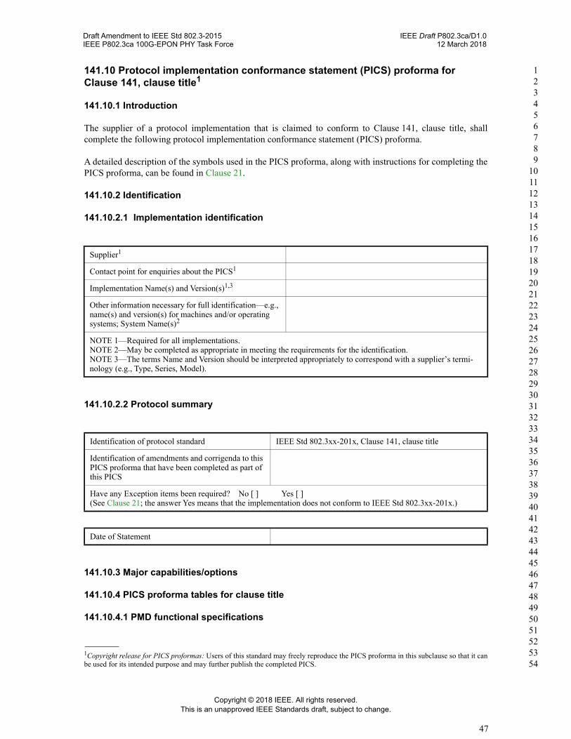
141.10 Protocol implementation conformance statement (PICS) proforma for Clause 141, clause title1
141.10.1 Introduction
The supplier of a protocol implementation that is claimed to conform to Clause 141, clause title, shall complete the following protocol implementation conformance statement (PICS) proforma.
A detailed description of the symbols used in the PICS proforma, along with instructions for completing the PICS proforma, can be found in Clause 21.
141.10.2 Identification
141.10.2.1 Implementation identification
141.10.2.2 Protocol summary
141.10.3 Major capabilities/options
141.10.4 PICS proforma tables for clause title
141.10.4.1 PMD functional specifications
1Copyright release for PICS proformas: Users of this standard may freely reproduce the PICS proforma in this subclause so that it can be used for its intended purpose and may further publish the completed PICS.
Supplier1
Contact point for enquiries about the PICS1
Implementation Name(s) and Version(s)1,3
Other information necessary for full identification—e.g., name(s) and version(s) for machines and/or operating systems; System Name(s)2
NOTE 1—Required for all implementations.NOTE 2—May be completed as appropriate in meeting the requirements for the identification.NOTE 3—The terms Name and Version should be interpreted appropriately to correspond with a supplier’s termi-nology (e.g., Type, Series, Model).
Identification of protocol standard IEEE Std 802.3xx-201x, Clause 141, clause title
Identification of amendments and corrigenda to this PICS proforma that have been completed as part of this PICS
Have any Exception items been required? No [ ] Yes [ ](See Clause 21; the answer Yes means that the implementation does not conform to IEEE Std 802.3xx-201x.)
Date of Statement
Copyright © 2018 IEEE. All rights reserved.This is an unapproved IEEE Standards draft, subject to change.
47

Draft Amendment to IEEE Std 802.3-2015 IEEE Draft P802.3ca/D1.0IEEE P802.3ca 100G-EPON PHY Task Force 12 March 2018
1 2 3 4 5 6 7 8 9
10 11 12 13 14 15 16 17 18 19 20 21 22 23 24 25 26 27 28 29 30 31 32 33 34 35 36 37 38 39 40 41 42 43 44 45 46 47 48 49 50 51 52 53 54
141.10.4.2 Management functions
Item Feature Subclause Value/Comment Status Support
Yes [ ]No [ ]
Yes [ ]
Item Feature Subclause Value/Comment Status Support
Yes [ ]
Yes [ ]No [ ]
Yes [ ]No [ ]N/A [ ]
Item Feature Subclause Value/Comment Status Support
Yes [ ]N/A [ ]
Yes [ ]No [ ]
N/A [ ]
Copyright © 2018 IEEE. All rights reserved.This is an unapproved IEEE Standards draft, subject to change.
48