
14 0 WIRE ROPE INSTALLATION GUIDE 12 2 4 0 FOR MOBILE...
8
WIRE ROPE INSTALLATION GUIDE FOR MOBILE CRANES 12 04/2014
Transcript of 14 0 WIRE ROPE INSTALLATION GUIDE 12 2 4 0 FOR MOBILE...

WIRE ROPE INSTALLATION GUIDE
FOR MOBILE CRANES
120
4/
20
14
Quick Installation Guide for Mobile Cranes®
-2-
Use and Care of Wire RopeSome Things Every User Should Know About Use and Care of Wire Rope
What follows is a brief outline of the basic information required to safely use wire rope
1. Wire rope WILL FAIL IF WORN OUT, OVERLOADED,MISUSED, DAMAGED, or IMPROPERLY MAINTAINED.
2. In service, wire rope loses strength and work capability. Abuseand misuse increase the rate of loss.
3. The MINIMUM BREAKING STRENGTH of wire rope appliesONLY to a NEW, UNUSED rope.
4. The Minimum Breaking Strength should be considered thestraight line pull with both rope ends fixed to prevent rotation,which will ACTUALLY BREAK a new, UNUSED, rope. TheMinimum Breaking Strength of a rope should NEVER BEUSED AS ITS WORKING LOAD.
5. To determine the working load of a wire rope, the MINIMUM orNOMINAL Breaking Strength MUST BE REDUCED by aDESIGN FACTOR (formerly called a Safety Factor). TheDesign Factor will vary depending upon the type of machineand installation, and the work performed. YOU must determinethe applicable Design Factor for your use.
For example, a Design Factor of “5" means that the Minimum-or Nominal Breaking Strength of the wire rope must beDIVIDED BY FIVE to determine the maximum load that can beapplied to the rope system.
Design Factors have been established by DIN, ISO, CEN,OSHA, ANSI, ASME and similar government and industrialorganizations.
No wire rope should ever be installed or used without fullknowledge and consideration of the Design Factor for theapplication.
6. WIRE ROPE WEAR OUT. The strength of a wire rope slightlyincreases after the break in period, but will decrease over time.When approaching the finite fatigue life span the breakingstrength will sharply decrease. Never evaluate the remainingfatigue life of a wire rope by testing a portion of a rope todestruction only. An indepth rope inspection must be part ofsuch evaluations.
7. NEVER overload a wire rope. This means NEVER use the ropewhere the load applied is greater than the working loaddetermined by dividing the Minimum Breaking Strength of therope by the appropriate Design Factor.
8. NEVER ‘SHOCK LOAD’ a wire rope. A sudden application offorce or load can cause both visible external damage (e.g.birdcaging) and internal damage. There is no practical way toestimate the force applied by shock loading a rope. Thesudden release of a load can also damage a wire rope.
9. Lubricant is applied to the wires and strands of a wire ropewhen manufactured. This lubricant is depleted when the ropeis in service and should be replaced periodically.
10. Regular, periodic INSPECTIONS of the wire rope, and keepingof PERMANENT RECORDS SIGNED BY A QUALIFIEDPERSON, are required by OSHA and other regulatory bodiesfor almost every rope installation. The purpose of inspection isto determine whether or not a wire rope may continue to besafely used on that application. Inspection criteria, includingnumber and location of broken wires, wear and elongation,have been established by DIN, ISO, CEN, OSHA, ANSI,ASME and other organizations.
IF IN DOUBT, REPLACE THE ROPE.
11. When a wire rope has been removed from service because itis no longer suitable, IT MUST NOT BE RE-USED ONANOTHER APPLICATION.
12. Every wire rope user should be aware of the fact that eachtype of fitting attached to a wire rope has a specific efficiencyrating which can reduce the working load of a rope assemblyor rope system, and this must be given due consideration indetermining the capacity of a wire rope system.
13. Some conditions that can lead to problems in a wire ropesystem include:
° Sheaves that are too small, worn or corrugated can causedamage to wire rope.
° Broken wires mean a loss of strength.° Kinks permanently damage a wire rope.° Environmental factors such as corrosive conditions andheat can damage a wire rope.
° Lack of lubrication can significantly shorten the usefulservice life of a wire rope
° Contact with electrical wire and the resulting arcing willdamage a wire rope
The above is the partially rewritten publication ‘WIRE ROPE AND SLING SAFETY BULLETIN’ . Some of it’s content was adapted to our specificrequirement and does not truly reflect the original as published by the WIRE ROPE TECHNICAL BOARD.

Quick Installation Guide for Mobile Cranes ®
-3-
Installation of Wire RopeForeword
In order to fully achieve the service life potential of Python™and standard wire rope for demanding crane jobs these step bystep instructions should be followed. They are intended toprevent rope damage caused by kinks, untwisting, and loosestrands, during handling and installation.
We realize that the ‘real world’ is not perfect. This applies alsoto wire rope installation. It is impossible to
cover ALL imaginable installation situations, location difficulties,and crane set ups. You will also find that these instructions arenot very different from the installation procedure of 6-strand or19x7 ropes. Many experienced Riggers may find some of thefollowing “old hat”. If you notice any omissions or have ideas thatwe can incorporate into this brochure we will be mostappreciative.
For a complete version of our Inspection-, Handling-, Installation-, and Instruction Guideplease e-mail us at [email protected]
If you have to field cut a rope
After attaching 3 hose clamps on eitherside of the cut mark, blade cut the rope.
Do not use a grinding wheel but a steelcutting blade; e.g.Elastic # 80EHT230-2.
Usually, you do not need to re-cut a wire rope. However, youmay encounter situations where it becomes necessary to shortenthe rope.
In cutting any wire rope special care MUST be taken inseizing the rope end.Two methods are suggested:
1) Seizing the rope end with soft iron wire.2) Seizing the rope end with hose clamps.
After cutting the rope it is good practice to braze or weld therope ends to ensure that they don’t unravel. Leave the seizing onthe rope for added holding strength. Be careful not to damage theseizing while brazing.
Cutting a rope with a torch may result in both uneven endsand damage to the seizing causing the strands to open up.
Rope diameter up to 14 mm (9/16") may be cut with a FELCOC16 hand cutter.
After bladecutting mountupright in a vice
Carefully melt and fuse together allindividual wires.
Properly fused wire rope end. If notdamaged during the fusing procedureclamps shall be left attached to the rope.
If hose clamps got damaged or are toobulky for the installation you need toreplace all 3 of them with a wire seizing.
In comparison, these are factory fusedand tapered ends done with aspecialized machine.
Quick Installation Guide for Mobile Cranes®
-4-
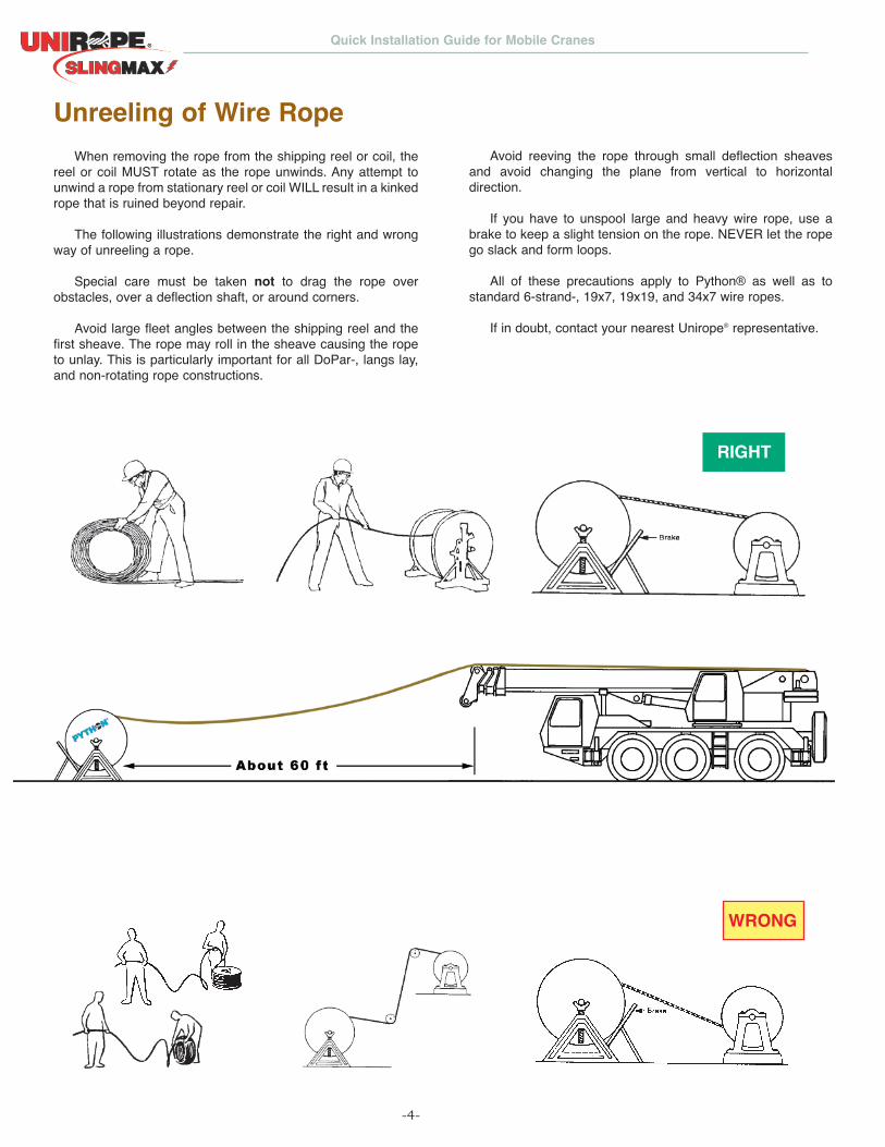
Unreeling of Wire RopeWhen removing the rope from the shipping reel or coil, the
reel or coil MUST rotate as the rope unwinds. Any attempt tounwind a rope from stationary reel or coil WILL result in a kinkedrope that is ruined beyond repair.
The following illustrations demonstrate the right and wrongway of unreeling a rope.
Special care must be taken not to drag the rope overobstacles, over a deflection shaft, or around corners.
Avoid large fleet angles between the shipping reel and thefirst sheave. The rope may roll in the sheave causing the ropeto unlay. This is particularly important for all DoPar-, langs lay,and non-rotating rope constructions.
Avoid reeving the rope through small deflection sheavesand avoid changing the plane from vertical to horizontaldirection.
If you have to unspool large and heavy wire rope, use abrake to keep a slight tension on the rope. NEVER let the ropego slack and form loops.
All of these precautions apply to Python® as well as tostandard 6-strand-, 19x7, 19x19, and 34x7 wire ropes.
If in doubt, contact your nearest Unirope® representative.
WRONG
RIGHT
Quick Installation Guide for Mobile Cranes ®
-5-
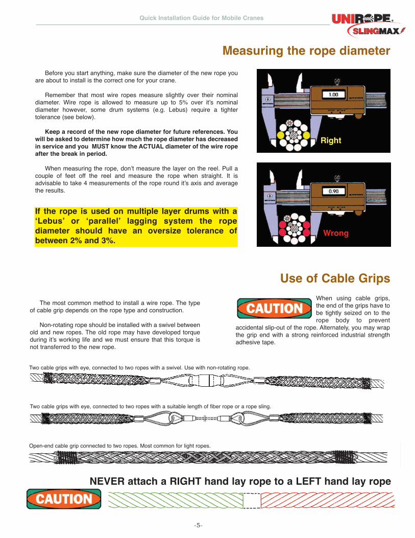
Use of Cable GripsThe most common method to install a wire rope. The type
of cable grip depends on the rope type and construction.
Non-rotating rope should be installed with a swivel betweenold and new ropes. The old rope may have developed torqueduring it’s working life and we must ensure that this torque isnot transferred to the new rope.
When using cable grips,the end of the grips have tobe tightly seized on to therope body to prevent
accidental slip-out of the rope. Alternately, you may wrapthe grip end with a strong reinforced industrial strengthadhesive tape.
Two cable grips with eye, connected to two ropes with a swivel. Use with non-rotating rope.
Open-end cable grip connected to two ropes. Most common for light ropes.
NEVER attach a RIGHT hand lay rope to a LEFT hand lay rope
Two cable grips with eye, connected to two ropes with a suitable length of fiber rope or a rope sling.
Measuring the rope diameterBefore you start anything, make sure the diameter of the new rope you
are about to install is the correct one for your crane.
Remember that most wire ropes measure slightly over their nominaldiameter. Wire rope is allowed to measure up to 5% over it’s nominaldiameter however, some drum systems (e.g. Lebus) require a tightertolerance (see below).
Keep a record of the new rope diameter for future references. Youwill be asked to determine how much the rope diameter has decreasedin service and you MUST know the ACTUAL diameter of the wire ropeafter the break in period.
When measuring the rope, don’t measure the layer on the reel. Pull acouple of feet off the reel and measure the rope when straight. It isadvisable to take 4 measurements of the rope round it’s axis and averagethe results.
Right
Wrong
If the rope is used on multiple layer drums with a‘Lebus’ or ‘parallel’ lagging system the ropediameter should have an oversize tolerance ofbetween 2% and 3%.
Quick Installation Guide for Mobile Cranes®
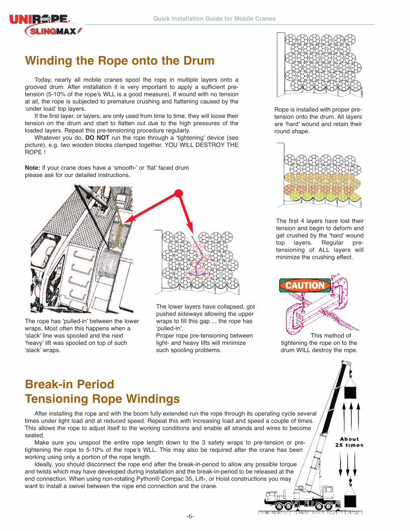
Winding the Rope onto the Drum
Break-in PeriodTensioning Rope Windings
Today, nearly all mobile cranes spool the rope in multiple layers onto agrooved drum. After installation it is very important to apply a sufficient pre-tension (5-10% of the rope’s WLL is a good measure). If wound with no tensionat all, the rope is subjected to premature crushing and flattening caused by the‘under load’ top layers.
If the first layer, or layers, are only used from time to time, they will loose theirtension on the drum and start to flatten out due to the high pressures of theloaded layers. Repeat this pre-tensioning procedure regularly.
Whatever you do, DO NOT run the rope through a ‘tightening’ device (seepicture), e.g. two wooden blocks clamped together. YOU WILL DESTROY THEROPE !
Rope is installed with proper pre-tension onto the drum. All layersare ‘hard’ wound and retain theirround shape.
The first 4 layers have lost theirtension and begin to deform andget crushed by the ‘hard’ woundtop layers. Regular pre-tensioning of ALL layers willminimize the crushing effect.
The rope has ‘pulled-in’ between the lowerwraps. Most often this happens when a‘slack’ line was spooled and the next‘heavy’ lift was spooled on top of such‘slack’ wraps.
The lower layers have collapsed, gotpushed sideways allowing the upperwraps to fill this gap ... the rope has‘pulled-in’.Proper rope pre-tensioning betweenlight- and heavy lifts will minimizesuch spooling problems.
This method oftightening the rope on to thedrum WILL destroy the rope.
Note: If your crane does have a ‘smooth-’ or ‘flat’ faced drumplease ask for our detailed instructions.
After installing the rope and with the boom fully extended run the rope through its operating cycle severaltimes under light load and at reduced speed. Repeat this with increasing load and speed a couple of times.This allows the rope to adjust itself to the working conditions and enable all strands and wires to becomeseated.
Make sure you unspool the entire rope length down to the 3 safety wraps to pre-tension or pre-tightening the rope to 5-10% of the rope’s WLL. This may also be required after the crane has beenworking using only a portion of the rope length.
Ideally, you should disconnect the rope end after the break-in-period to allow any possible torqueand twists which may have developed during installation and the break-in-period to be released at theend connection. When using non-rotating Python® Compac 35, Lift-, or Hoist constructions you maywant to install a swivel between the rope end connection and the crane.
-6-
Quick Installation Guide for Mobile Cranes ®
-7-
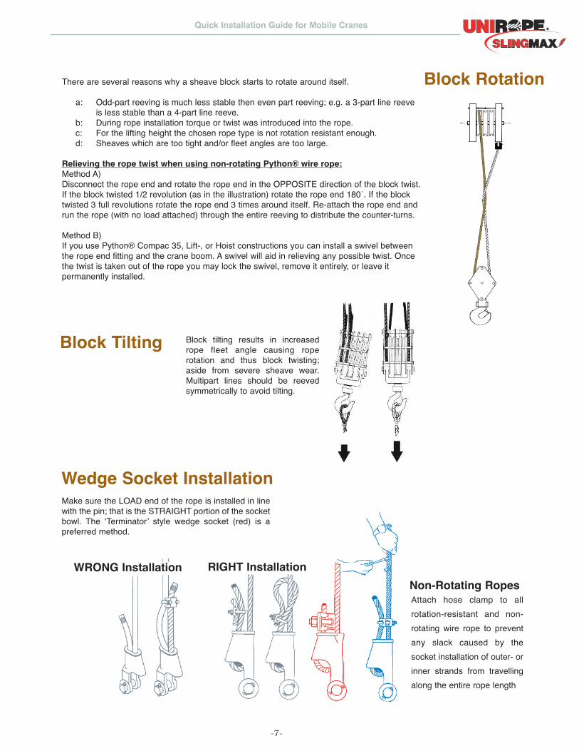
Block tilting results in increasedrope fleet angle causing roperotation and thus block twisting;aside from severe sheave wear.Multipart lines should be reevedsymmetrically to avoid tilting.
Make sure the LOAD end of the rope is installed in linewith the pin; that is the STRAIGHT portion of the socketbowl. The ‘Terminator’ style wedge socket (red) is apreferred method.
Block Rotation
Block Tilting
Wedge Socket Installation
There are several reasons why a sheave block starts to rotate around itself.
a: Odd-part reeving is much less stable then even part reeving; e.g. a 3-part line reeve is less stable than a 4-part line reeve.
b: During rope installation torque or twist was introduced into the rope. c: For the lifting height the chosen rope type is not rotation resistant enough.d: Sheaves which are too tight and/or fleet angles are too large.
Relieving the rope twist when using non-rotating Python® wire rope:Method A)Disconnect the rope end and rotate the rope end in the OPPOSITE direction of the block twist.If the block twisted 1/2 revolution (as in the illustration) rotate the rope end 180˙. If the blocktwisted 3 full revolutions rotate the rope end 3 times around itself. Re-attach the rope end andrun the rope (with no load attached) through the entire reeving to distribute the counter-turns.
Method B)If you use Python® Compac 35, Lift-, or Hoist constructions you can install a swivel betweenthe rope end fitting and the crane boom. A swivel will aid in relieving any possible twist. Oncethe twist is taken out of the rope you may lock the swivel, remove it entirely, or leave itpermanently installed.
WRONG Installation RIGHT InstallationNon-Rotating RopesAttach hose clamp to allrotation-resistant and non-rotating wire rope to preventany slack caused by thesocket installation of outer- orinner strands from travellingalong the entire rope length

O nt a ri oUnirope L imited3070 Universa l Dr iveMiss issauga, ON L4X 2C8P: 905 624 5131 1 800 457 9997F: 905 624 9265
E d m o nt o nUnirope L imited5613 70th StreetEdmonton, AB T6B 3P6P: 780 6 4 4 9 0 0 0F: 780 644 9100
M o nt re a lUnirope L imited555 Gougeon Str.St . Laurent , QC H4T 2B4P: 514 3 3 9 5 4 4 41 877 239 5444F: 514 339 5556
E: [email protected]© Unirope L imited 2014
MAKE SURE YOU CHECKOUT OUR EXTENSIVE
WIRE ROPE SECTION ONOUR WEBSITE
®
WIRE ROPE 12
Selection | Removal Criteria | Constructions | Specifications
07
/2
01
2
®
50 years have passed since Unirope® was first incorporated in 1956 asWDI Wire Rope of Canada Limited. From small humble beginnings totoday’s three modern facilities with over 100,000 sqft we’ve come a longway since.Over the past decades Unirope® has become one of the prime wire ropedistributors and rigging supply companies in Canada serving themanufacturing-, automotive-, construction-, entertainment-, marine-,steel-, utility-, and power generation industries.
Our testing equipment is certified by Lloyd’s Register of Shipping andcalibrated to ASTM E99. Where applicable, our ropes meet internationalperformance standards, including CSA, EN, ISO, ASTM, RR-W-410


![SFH 4259 - Farnell · Trailer: 13. 0 Direction of unreeling ±0.25 min. 160 mm * min. 400 mm * *) Dimensions acc. to IEC 60286-3; EIA 481-D Reel dimensions [mm] A W N min W 1 W 2](https://static.fdocuments.net/doc/165x107/5fd8cf8fe413825b586b82dc/sfh-4259-trailer-13-0-direction-of-unreeling-025-min-160-mm-min-400-mm.jpg)
![Paper survey€¦ · Paper survey [1] Unreeling Netflix: Understanding and Improving M ulti-CDN Movie Delivery, IEEE Infocom 2012 [2] Algorithmic Nuggets in Content Delivery, ACM](https://static.fdocuments.net/doc/165x107/60545a440a6cb40dc14de501/paper-survey-paper-survey-1-unreeling-netflix-understanding-and-improving-m-ulti-cdn.jpg)