1383 IEPC-93-151
8
1383 IEPC-93-151 A LARGE HIGH VACUUM, HIGH PUMPING SPEED SPACE SIMULATION CHAMBER FOR ELECTRIC PROPLUSION Stanley P. Grisnik NASA Lewis Research Center, Brookpark,Oh. James E. Parkes Sverdrup Technology, Inc., Brookpark, Oh Abstract Testing high power electric propulsion malfunctions and/or facility shutdown results in devices poses unique requirements on space immediate notification of the proper personnel to simulation facilities. Very high pumping speeds aid in preventing damage to the facility or test are required to maintain high vacuum levels hardware. Graphic panels with an annunciator while handling large volumes of exhaust system displays the current status of the vacuum products. These pumping speeds are significantly pumps, gaseous and liquid nitrogen systems, higher than those available in most existing gaseous helium system, propellant feed systems, vacuum facilities. There is also a requirement for and freon refrigeration system. relatively large vacuum chamber dimensions to Research testing can be controlled and minimize facility wall/thrsuter plume monitored from either the facility control room interactions and to accomodate far field plume or locally, near the individual test ports located diagnostic measurements, at various places around the chamber. These test A 15 ft.(4.57 m) diameter by 63 ft. ports allow quick turn around time for (19.2m) long vacuum chamber at NASA Lewis experiment change-out by eliminating the need Research Center is described in this paper. The to pumpdown the main chamber. chamber utilizes oil diffusion pumps in The test ports, power supplies,and combination with cryopanels to achieve high propellant supply systems are tied into a vacuum pumping speeds at high vacuum levels, computer controlled interlock system. This The facility is computer controlled for all phases system prevents improper or dangerous of operation from start-up, through testing, to operation by personnel conducting hardware shutdown. The computer control system tests. increases the utilization of the facility and reduces the manpower requirements needed for Chamber and SuDport Equipment facility operations. Description Introduction Vacuum Facility #5 is constructed of 1/8 inch thick 304 stainless steel cladding on The NASA Lewis 15 ft. (4.57m) 9/16 inch thick mild steel. All internal diameter by 63 ft.(19.2m) long vacuum chamber facility specific components are fabricated from (Vacuum Facility #5) is located in the Electric stainless steel, aluminum, teflon, buna N, or Power Laboratory (figure 1&2). Vacuum Facility viton. The vacuum piping from the chamber to #5 was originally designed and built for ion and the rough pumps is constructed of mild steel. plasma thruster research along with spacecraft Both 15 ft. diameter end caps are and spacecraft component testing.' Its use easily removable for installation of large test today has expanded to encompass all types of articles (fig. 3). A 10-ton crane located at the Electric Propulsion testing in addition to testbed east end and a 2-ton crane located at the west Photovoltaic and Space Station components, end of the chamber aid in test article Through computer control, the facility is installation. Test articles of up to 1000 Ibs. able to monitor its health and take corrective (454Kg) can be safely hung from the top of the action as needed. This reduces the likelihood of chamber. facility damage from equipment failure or In the center of the chamber is a 15 ft. improper operation. Major equipment dia louvered wall (mid tank shield ).The louvers 1
Transcript of 1383 IEPC-93-151

1383 IEPC-93-151
A LARGE HIGH VACUUM, HIGH PUMPING SPEEDSPACE SIMULATION CHAMBER FOR ELECTRIC PROPLUSION
Stanley P. GrisnikNASA Lewis Research Center, Brookpark,Oh.
James E. ParkesSverdrup Technology, Inc., Brookpark, Oh
Abstract
Testing high power electric propulsion malfunctions and/or facility shutdown results indevices poses unique requirements on space immediate notification of the proper personnel tosimulation facilities. Very high pumping speeds aid in preventing damage to the facility or testare required to maintain high vacuum levels hardware. Graphic panels with an annunciatorwhile handling large volumes of exhaust system displays the current status of the vacuumproducts. These pumping speeds are significantly pumps, gaseous and liquid nitrogen systems,higher than those available in most existing gaseous helium system, propellant feed systems,vacuum facilities. There is also a requirement for and freon refrigeration system.relatively large vacuum chamber dimensions to Research testing can be controlled andminimize facility wall/thrsuter plume monitored from either the facility control roominteractions and to accomodate far field plume or locally, near the individual test ports locateddiagnostic measurements, at various places around the chamber. These test
A 15 ft.(4.57 m) diameter by 63 ft. ports allow quick turn around time for(19.2m) long vacuum chamber at NASA Lewis experiment change-out by eliminating the needResearch Center is described in this paper. The to pumpdown the main chamber.chamber utilizes oil diffusion pumps in The test ports, power supplies,andcombination with cryopanels to achieve high propellant supply systems are tied into avacuum pumping speeds at high vacuum levels, computer controlled interlock system. ThisThe facility is computer controlled for all phases system prevents improper or dangerousof operation from start-up, through testing, to operation by personnel conducting hardwareshutdown. The computer control system tests.increases the utilization of the facility andreduces the manpower requirements needed for Chamber and SuDport Equipmentfacility operations. Description
Introduction Vacuum Facility #5 is constructed of1/8 inch thick 304 stainless steel cladding on
The NASA Lewis 15 ft. (4.57m) 9/16 inch thick mild steel. All internaldiameter by 63 ft.(19.2m) long vacuum chamber facility specific components are fabricated from(Vacuum Facility #5) is located in the Electric stainless steel, aluminum, teflon, buna N, orPower Laboratory (figure 1&2). Vacuum Facility viton. The vacuum piping from the chamber to#5 was originally designed and built for ion and the rough pumps is constructed of mild steel.plasma thruster research along with spacecraft Both 15 ft. diameter end caps areand spacecraft component testing.' Its use easily removable for installation of large testtoday has expanded to encompass all types of articles (fig. 3). A 10-ton crane located at theElectric Propulsion testing in addition to testbed east end and a 2-ton crane located at the westPhotovoltaic and Space Station components, end of the chamber aid in test article
Through computer control, the facility is installation. Test articles of up to 1000 Ibs.able to monitor its health and take corrective (454Kg) can be safely hung from the top of theaction as needed. This reduces the likelihood of chamber.facility damage from equipment failure or In the center of the chamber is a 15 ft.improper operation. Major equipment dia louvered wall (mid tank shield ).The louvers
1
IEPC-93-151 1384
are electrically moveable from outside of the charged with D.C. 705 oil.The diffusion pumpsfacility. The mid tank shield is used to protect are backed by four 3000 CFM (85700 1/s) rotarythe cryopanel surface from direct impingment by lobe type blowers . The blowers discharge intoresearch thruster exhaust plumes. Instrumenta- four 530 CFM (15150 I/s) rotating piston roughtion, power and propellant can be routed into pumps. (fig. 6) Above the diffusion pumps arethe chamber through flanged ports of various single bounce optically dense chevron type trapssizes. There are 18-12 inch diameter ports, 1-24 cooled to -25 degrees F.inch diameter port, 11-36 inch diameter ports A closed loop refrigeration system, anand 264-2 1/4 inch I.D. ports. These can be economical alternative to liquid nitrogen, coolsfitted with quartz windows for access by optical the traps. The refrigeration system isdiagnostic equipment, if required, comprised of redundant twenty ton cooling
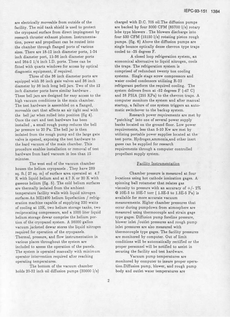
Three of the 36 inch diameter ports are systems. Single stage screw compressors andequipped with 36 inch gate valves and 36 inch water cooled condensors utilizing R-22diameter by 36 inch long bell jars. Two of the 12 refrigerant perform the required cooling. Theinch diameter ports have similar hardware . system delivers freon at -52 degrees F (-47 C)These bell jars are designed for easy access to the and 38 PSIA (255 KPa) to the chevron traps. Ahigh vacuum conditions in the main chamber. computer monitors the system and after manualThe test hardware is assembled on a flanged, startup, a failure of one system triggers an auto-moveable cart that affects an air tight seal with matic switchover to the backup system.the bell jar when rolled into position (fig 4). Research power requirements are met byOnce the cart and test hardware has been "patching" into one of several power supplyinstalled , a small rough pump reduces the bell banks located on the ground floor. Low powerjar pressure to 20 Pa. The bell jar is then requirements, less than 5-10 Kw are met byisolated from the rough pump and the large gate utilizing portable power supplies located at thevalve is opened, exposing the test hardware to test ports. Hydrogen,ammonia,and other inertthe hard vacuum of the main chamber. This gases can be supplied for researchprocedure enables installation or removal of test requirements through a computer controlledhardware from hard vacuum in less than 15 propellant supply system.minutes.
The west end of the vacuum chamber Facility Instrumentation
houses the helium cryopanels . They have 289sq. ft.( 27 sq. m) of surface area operated at 4.7 Chamber pressure is measured at fourK with liquid helium and at 4.7 K or 20 K with locations using hot cathode ionization gages. Agaseous helium (fig. 5). The cold helium surfaces spinning ball rotameter that relates gas
are thermally isolated from the ambient viscosity to pressure with an accuracy of +/- 2%temperature facility walls with liquid nitrogen 0 10E-3 to 10E-7 torr ( 1.3E-3 to 1.3E-5 Pa) issurfaces.An ME1400 helium liquefaction / refrig- available for more accurate vacuumeration machine capable of supplying 330 watts measurements. Higher chamber pressures thatof cooling at 13K, two helium storage tanks, two occur during pumpdown from atmosphere arereciprocating compressors, and a 1000 liter liquid measured using thermocouple and strain gagehelium storage dewar comprise the helium por- type gages. Diffusion pump foreline pressure,tion of the cryopanel system. A 56000 gallon blower inlet /outlet pressures and rough pumpvacuum jacketed dewar stores the liquid nitrogen inlet pressures are also measured withrequired for operation of the cryopanels. thermocouple type gages. The facility pressuresThermal, pressure, and flow instrumentation in are monitored by computer. Out of limitvarious places throughout the system are conditions will be automatically rectified or theincluded to assess the operation of the panels, proper personnel will be notified to assist inThe system is operated manually with minimum securing the facility and test hardware.operator intervention required after reaching Vacuum pump temperatures areoperating temperatures. monitored by computer to insure proper opera-
The bottom of the vacuum chamber tion.Diffusion pump, blower, and rough pumpholds 20-32 inch oil diffusion pumps (30000 1/s) body and outlet water temperatures are
2

1385 IEPC-93-151
monitored. A pump operating above normal 100 millitorr (13 Pa).operating temperatures will be automatically The diffusion pumps requireshutdown, while the remaining pumps keep the approximately 30 minutes to reach operatingchamber at vacuum. An alarm will sound at the temperature. If they are turned on when thefacility ,alerting personnel to the problem. chamber is at 100 millitorr (13Pa), it will takeDuring unattended operation , a problem serious 40 minutes to reach 5x10E-5 torr (6.7x10E-3enough to require operator intervention will Pa). After 15 hours the chamber is at its ulti-cause an alarm to sound at the NASA mate vacuum level of 8x10E-7 torr (l.lxlOE-4firestation. The cryopanel temperatures are Pa).monitored from 8 different locations in a single The crypanels take approximately 14 toreadout display. Five temperatures within the 16 hours to cool down from 300 K to 10 K. Thehelium refrigerator are also monitored.The chamber is pumped down to lxl0E-3 torrhelium temperatures are acquired by low (1.3x10E-I Pa) with the blowers and roughtemperature diodes. There are 28 thermocouples pumps ,at which point the cooling of the cryopa-monitoring temperatures on the liquid nitrogen nels is begun. At approximately 40K panelportion of the cryopanels. The liquid nitrogen temperature and 4x10E-4 chamber pressure, theboil-off is vented to atmosphere through a closed mechanical pumps are isolated from theloop feedback system that utlizes pressure chamber. Within 2 hours the chamber is attransducers to keep a fixed head of liquid in the 8x10E-7 torr (l.1xl0E-4 Pa), and ready topanels. Helium gas flowrate to the refrigerator / cryopump all gases with a condensation pointliquifier is also monitored. The cryopanel system above 10K.can run unattended after a manual start-up. Venting the chamber to atmosphereHelium flow or system pressure changes require after diffusion pump operation is accomplishedoperator attendance. Compressor malfunction, as follows. First, the diffusion pumps are turnedresulting in loss of panel cooling, will alert the off and allowed to cool. After 10 minutes theyfacility personnel for corrective action to be have cooled sufficiently that the diffusion pumptaken. jets collapse and cease pumping. The pump oil is
Facility services such as air pressure, further cooled to 120 degrees F (49 C) in 2nitrogen service gas pressure, and water hours. The cooling to the chevron traps is thenpressure are monitored to ensure adequate stopped and it takes approximately 4 hours forsupplies for proper facility operation. The them to warm above the dew point for the day.criticality of a loss of one of the mentioned When the freon cooling is stopped, the blowersservices is assessed by the computer and and rough pumps are turned off. Finally thecorrective action is taken. Proper personnel are chamber vent valve is opened and thenotified if operator intervention is required. chamber is bled up to atmosphere with air or
nitrogen in approximately 45 minutes.Facility Operation Venting the chamber to atmosphere
after cryopanel operation is accomplished byVacuum Facility #5's high pumping shutting down the refrigeration system and stop-
speed is attributed to its two pumping systems. ping the flow of liquid nitrogen to the baffle.The 289 sq. ft. (27 sq.m) liquid or gaseous The rough pumps and blowers are then operatedheilum cryopanels and 20-32 inch diameter to remove the gases from the chamber as theydiffusion pumps backed by 4- 3000 CFM (85700 vaporize from the panels. After the cryopanelsl/s) rotary lobe blowers which exhaust into 4- warm to a temperature above the dew point (15530 CFM (15150 I/s) rotary piston pumps. (fig. hours), the rough pumps and blowers can be6) isolated from the chamber. The chamber can
Evacuation of the vacuum chamber is then be vented to atmosphere.accomplished by first reducing the chamber The diffusion pumped pumping speed ofpressure to 10 torr (1.3E3 Pa) with the four Vacuum Facility #5 has been determined forrotary piston pumps. This takes approximately various configurations as shown in figure #7. 2
35 minutes. The rotary lobe blowers are then The maximum pumping speed for air is 250,000started and within 5 minutes the chamber is at 1/s at 10E-4 to 10E-6 torr, and for hydrogen it is
3

IEPC-93-151 1386
660,000 1/s at 10E-4 torr.The cryopumped pumping speed of the
chamber has been determined for Argon and
Xenon. The maximum pumping speed for Argon
is 300,000 I/s at 10E-4 torr, and for Xenon it is
150,000 1/s at 10E-5 torr.Total facility pumping speeds in excess
of 450,000 1/s for Argon is possible using both
pumping systems simultaneously.
References
1.Finke,R.C.; Holmes,A.D.;Keller,T .A.: Space
Environment Facility For Electric Propulsion
Systems Research. NASA TN D-2774, May 1965.
2.Ibid.
4

1387 IEPC-93-151r 56 000 gal LN2 Dwar
Freon system /compressors Vacuum fachly -
r- GHe storage
4\1
Vacuumc.y=S 5 Vacuum faclily 15
roughing pumps
C-90-08357
Figure 1.--Electric Power Laboratoy; st floor.
Vacuum facily #6 . -
-- " ., . . - . , .
Vacuum facilty 85 -- e
C-90.08360
Figure 2.-Electric Power Laboratory 2nd floor.
A AtIEP-93-1 51 1388
Figure 3.-Vacuum facility 05; moveable endcap.
Fgiu 4 -Test hardware nd moweehl. cam

1389 IEPC-93-1 51Midta~cMoveable
Figure S.-Vacuum facilty 0IS I t cliami x 63 ft overaJ&
VacLACFM)
)- Rotbon
(530 CF)US
Fiue6-aum aiit 5 aum iig

IEPC-93-151 1390
-Hydrogen; no baps---- Hyroeu l o~-r&grn-00d traps----Ar no trays-- Mansucturs' troreict air; r, traps
A&;6 wd-nogn-=o4.rauyAir wuter-cooledtbays
12ft10'
o g
0. 40 //J/
Pressure, torrFigure 7.-Pump speed versus pressure diffusion~ pumps only
(ref. 1).