133.20-2 Reactor, Boiler Auxiliaries - Course 133 ... Library/20041302.pdf · Reactor, Boiler &...
24
133.20-2 Reactor, Boiler & Auxiliaries - Course 133 MODERATOR SYSTEM & EQUIPMENT The basic main and auxiliary moderator system requirements which must be met are listed and discussed in turn. These are described in general terms to bring out the principles involved and the descriptions of each of the sub- systems are not intended to be specific to a particular station but will be applicable to most of cur stations with seme variations. Major differences in some systems do occur however as our units increase in size but these will be pointed out. To provide an overall picture of complete systems, specific flow sheets (Pickering GSA) are included at the end of the text in this, and other sections, for reference if greater detail is required for a few of the major systems. MAIN MODERATOR SYSTEMS (a) Circulating and Heat removal system. (b) Level Control and Helium Cover Gas System. (c) Liquid Poison Addition System. (d) Purification System. AUXILIARY MODERATOR SYSTEM (e) Reactivity Mechanism Cooling. (f) Calandria, Dump Port and Dump Tank Spray Cooling. (g) Emergency Transfer of Moderator to PHT System. (11) Leakage Collect L::m and Dz 0 Recovery. (i) DzO Addition and Transfer. 1977 -1-
Transcript of 133.20-2 Reactor, Boiler Auxiliaries - Course 133 ... Library/20041302.pdf · Reactor, Boiler &...

133.20-2
Reactor, Boiler & Auxiliaries - Course 133
MODERATOR SYSTEM & EQUIPMENT
The basic main and auxiliary moderator system requirementswhich must be met are listed and discussed in turn.
These are described in general terms to bring out theprinciples involved and the descriptions of each of the subsystems are not intended to be specific to a particular stationbut will be applicable to most of cur stations with semevariations. Major differences in some systems do occur howeveras our units increase in size but these will be pointed out.
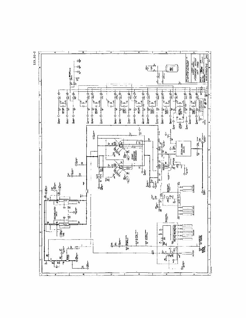
To provide an overall picture of complete systems, specificflow sheets (Pickering GSA) are included at the end of the textin this, and other sections, for reference if greater detail isrequired for a few of the major systems.
MAIN MODERATOR SYSTEMS
(a) Circulating and Heat removal system.
(b) Level Control and Helium Cover Gas System.
(c) Liquid Poison Addition System.
(d) Purification System.
AUXILIARY MODERATOR SYSTEM
(e) Reactivity Mechanism Cooling.
(f) Calandria, Dump Port and Dump Tank Spray Cooling.
(g) Emergency Transfer of Moderator to PHT System.
(11) Leakage Collect L::m and Dz 0 Recovery.
(i) DzO Addition and Transfer.
A~ril 1977 -1-

133.20-2
(a) MODERATOR CIRCULATION AND HEAT REj\10VAL SYSTEIvl
Heat Production
133.20-2
Heat input to the moderator is generated from thefollowing sources:
directly from
and indirectly from
neutron slowing down
y ray absorbtion
heat radiation from fuel channels
calandria structure heating
calandria tube heating
dump tank heating
-2-
The direct contribution makes up a large heat sourcewhich is unfortunately not yet practical to utilizeeconomically for say turbine condensate reheat or buildingheating.
Table 1 lists the moderator heat production for allour stations together with the normal moderator operatingtemperature, the cover gas pressure in the calandriausually being slightly above atmosphere. The maximum andminimum temperature limits are set ,by the allowable thermalstresses in the calandria and its end shields.
Table 2 breaks down the various individual heat sourcesfor Pickering GS moderator system, which is fairly typical.
TABLE 1
STATION MODERATOR HEAT PRODUCTION
DouglasNPD Point Pickering Bruce
thermal heat produc-ed in fuel channels 82 657 1655 2375
HH(th)*
Total heat appear-ing in moderator 6 37 89.6 155circuit MW(th)
average moderator30°C ,50°C 70°C 84°Ctemperature
* does not include primary pump energyappearing in PHT system.

......ww.""o,IV
T\1oderatorDistributi
............-lreacA."'r
Dump Tank
PumpSuctionHeaders
/'----
HX2
~.
.-""'"
, <:-----t><J---1
4
5
• ....t':::x:::" I
) HXl
~"
toIIIUl/-'-0
~0p.CDIiIIIrt-0Ii
0 ------/-'-Ii Balance0C Pipe......IIIrt-/-'.0::s(J)
'<Ulrt-CDS........I"Ij/-'-0;:.;-CDIi/-'-::s
.-Q
GJJ'::t:"--
,w

",
"\ ..' ..
....
'·i'..~
~r~.,.;.Qi:;:;~
~~
n.\! ~':~~. ~-':::""'~,~c"'·. '.'t: . .:~'I'~~. ;,l:_ '('~'
~
CONTAINMENT WALL
BOOSTERFEEDERS
2......
CAlANDRIA
~ . . . .J BOOSTER BY~PASS
u\~MODEI~ATOR
DISTRIBUTION
HEADER. t t t , t , , .. It"·/t-~
: ~
k ,<'.
L".",.,.,.,.......~·"7ry----.=-c<><;="l--==~'O+Ft:::''''''"'''''.".,.,.,,-,;''''''''''-db.-:--;p''*''..-.r.~~. ~':A+:.<;«"" .:::c~ <:~~·{1'!i-';-;·r; ..;l.';'--~"'W; ~~~.:~~jj~~~\~.l,;
TYPICAL r-
BOOSTER
r-i ~~
:~EXPANSION
Z1 TANK
~
~~
~..:..
I;q}::(~,:~!.T;~:- ~c::
.~~ }t
~.''.~.,..~t."
I"'~I
Moderatnr Circulation Circuit WithoutDump Tank (Bruce GSA)
Figure 2:
",
"~,I I HEAT EXCHANGER. ~
!f}f~.'~""C;i>'C:?",;"; I~">f. MAIN PUM,:,"", ~:~,U,:Pb, H~~,",,~"7T.,..,..,.,EX~c_H_A_N.=-3
.. . ~ .~. ~ . '..., >," ."...... .. ..,"
.~""i:';/!.::;<'(~i;':..S!')<c:l}"~'ij{~;~ ;j;::;~>,;,. ,,"".~,:.,;t:J;:;~f!fJ1f;~?f~B.1i1f~;;tt;";;':; ll';: ;" I
NI
aN.MMr-i
NO.
SPRING HANGERS ----
133.20-2
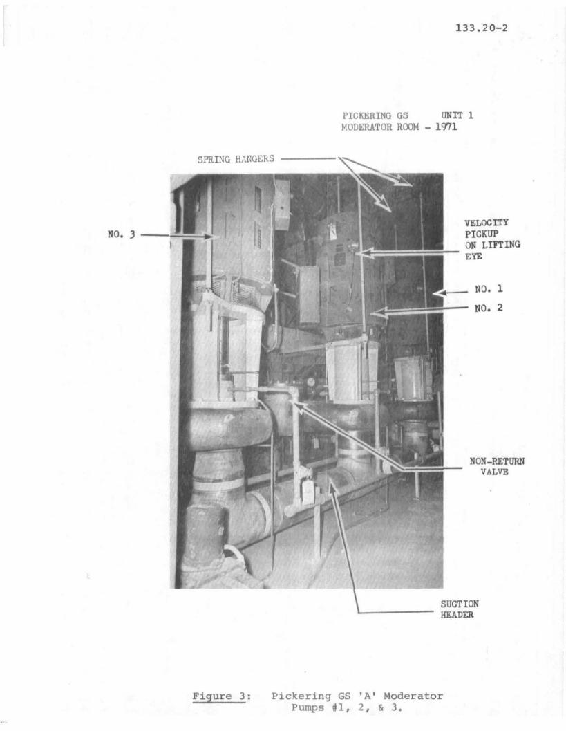
PICKERING GS UNIT 1MODERATOR ROOM - 1971
VELOCITYPICKUPON LIFTINGEYE
NO.1
NO. 2
NON-RETURNVALVE
SUCTIONHEADER
Figure 3: P1ckering GS 'A' ModeratorPumps #1, 2, & 3.
133.20-2
TABLE 2
BREAKDOWN OF MODERATOR HEAT PRODUCTION
(Pickering GS)
IM"w (th) IHeat Source
neutron moderation + y ray absorbtion 82
heat radiation from fuel channels 2.6
heat produced in calandria tubes 2.5
heat produced in calandria structure 2.4
heat produced in dump tank 0.1
total heat in moderator circuit B9.6
Basic Circulating System
A typic basic circulation system is shown inFigure 1 (Pickering A). Two pairs of pumps PI, P2 andP4, P5 are required in parallel to handle the flowsinvolved during normal operation with one standby pumpset P3 available in case of failure of one pump ofeither pair. Two heat exchangers HXl and HX2 areplaced after the pump outlet headers rather than on theinlets (as is done in the PHT system) to utilize thehigher pressure, at the pump discharge, on the D20 tubeside of the exchangers preventing inleakage of shellside H20 service cooling water.
In addition this arrangement enables the pump tohave a higher suction head by avoiding the smallerpressure on the heat exchanger outlet due to the pressuredrop in the tubes (~200-300 kPa) which is larqe comparedto the pump discharge pressure required in this lowpressure system.
Pump suction is from the bottom of the calandria,via two outlets, and discharge is back into thecalandria via a distribution header into two inletsthrough upturned nozzles just below the calandria midpoint. This provides good mixing and a uniform temperature distribution. Normally there is no spillage overthe dump ports all th·? hec:l'l~' water entering thecalandria leaving by the nual outlets. To providepump up after monerator dump n third line is providedfrom the dump tank to the pump suction headers as shown.Figure 3 illustrates pumpsets PI, P2, P3 at Pickering GSA.
-6-
Gas Chromatograph
Gas Chromatograph
OxY~ren
Addi.tion
Flamerrestor
MoistureSeparator
• ), 'ulO
, (: • lllg•
Dump Tank
Figure 4:
D20 from ModDistribution
Header
HeAddition ____
~e Cover Gas Circuit
IIe:lium'rank
/
.....wwI\)oI
I\)
133.20-2
Moderator DistributionHeader
He froncover gasSystem
DelayTank
Agitator
Boron orGadolinium:'~ixing Tan
":8-
~-~---~
Figure 5:
lDUJT'tp Tank
--======------==---===--
Injection Pump
Liquid Poison Addition SysteM

FROM MODERATOR HEAT EXCHANGER OUTLET LINE-,
IX COLUMNS
.;- RESINADDITION
I~
I
--...---rro MODERATOR PUMP SUCTION
Figure 6: Moderator Purification System
RESIN'- I ~TRANSFER
.......w.,.)
'voI
IV

133.20-2
Isolation Provision
It must be possible to isolate pumpsets and heatexchangers for maintenance. Figure I shows the positionof typical gate valves provided for this purpose.Isolation, in this case, is provided for each bank ofpumps and for each heat exchanger individually.
Variations on the basic circulating system.
The layout of the system described above isfollowed in all our stations with some minor variations.For instance, at NPD only 3 moderator pumps are used(2 x 50% and 1 on-standby) and a single heat exchangeris used. Circulation here takes place by suction fromthe dump tank, through the pumping system, into thebottom of the calandria and a continual spillage overthe dump tank port refills the dump tank to completethe circuit. Isolation is provided in this case foreach pump individually.
At Bruce the differences are illustrated in Figure2. The absence of a dump tank at Bruce and the presenceof a large number of boosters necessitates the inclusionof the booster cooling in the main circuit rather thanas an auxiliary cooling system. This circuit consistsof 2 identical halves each comprising a pumpset and aheat exchanger with cross ties allowing for operatingof either half circuit independently, normal operationbeing with one pump, the other being standby. Themain flow distributes itself through 16 booster rodfeeders into the top of the calandria and via a by passline, limiting the maximum velocity flow through theboosters. Due to the necessity of booster cooling atall times auxiliary moderator pumps are provided in thiscase for booster fuel insertion and loss of the mainpumpsets. Suction of these pumps can either be from thecalandria or from floor drains and discharge into themain distribution headers.
An additional dldnge at Bruce dIlU un Pickering B,due to dump tank absence, is the inclusion of anexpansion tank tied into the calandria, Figure 2. BynccoIT~odating Dwell and shrinkage of the moderator themoderator level is maintained and controlled at itsnominally maximum value by an air feed and bleed system.
-10-

Shut Off Rods
Flux Honitor Rods
Moderator Distribution Header
~lo. Calandria Sprays:> A-.. '"I
I =-::,. or X j~ Dump Tank Sprays
Adjuster Rods
I
~ I ;> "*"~ Dump Port Sprays
Emergency InjectionTo PHT System
--'"
"Moderator Sample stati.on
Transfer to Upgrader
It--'
--- -----~
Figure 7:
He Compressor D2 0 Seal Supply
Moderator Auxiliary System Lines
I-'wW
NoIto

-12-
133.20-2
(b) LEVEL CONTROL AND HELIUM COVER GAS SYSTEM
7\" I'""'L .. , ..... ro~~ .... ..; ......~ro .. ,~ .... "" n.:,...l,t"'""t. ..... .;,...,~ 7\ !='loV"'O " .... ..:,;11'7;1""'11~.c-.a. ........... \,J\,A.L oJl.,..\,A'-..L'-JJ. ... ~, .....1:" '-'-'" J,..-I-"-"J~'-'..L.. ..... .L.L'::J S.J,.I '--1, ..... ............... 41 ......... ":'
a dump tank for reactor trip and moderator level variationfor reactor control.
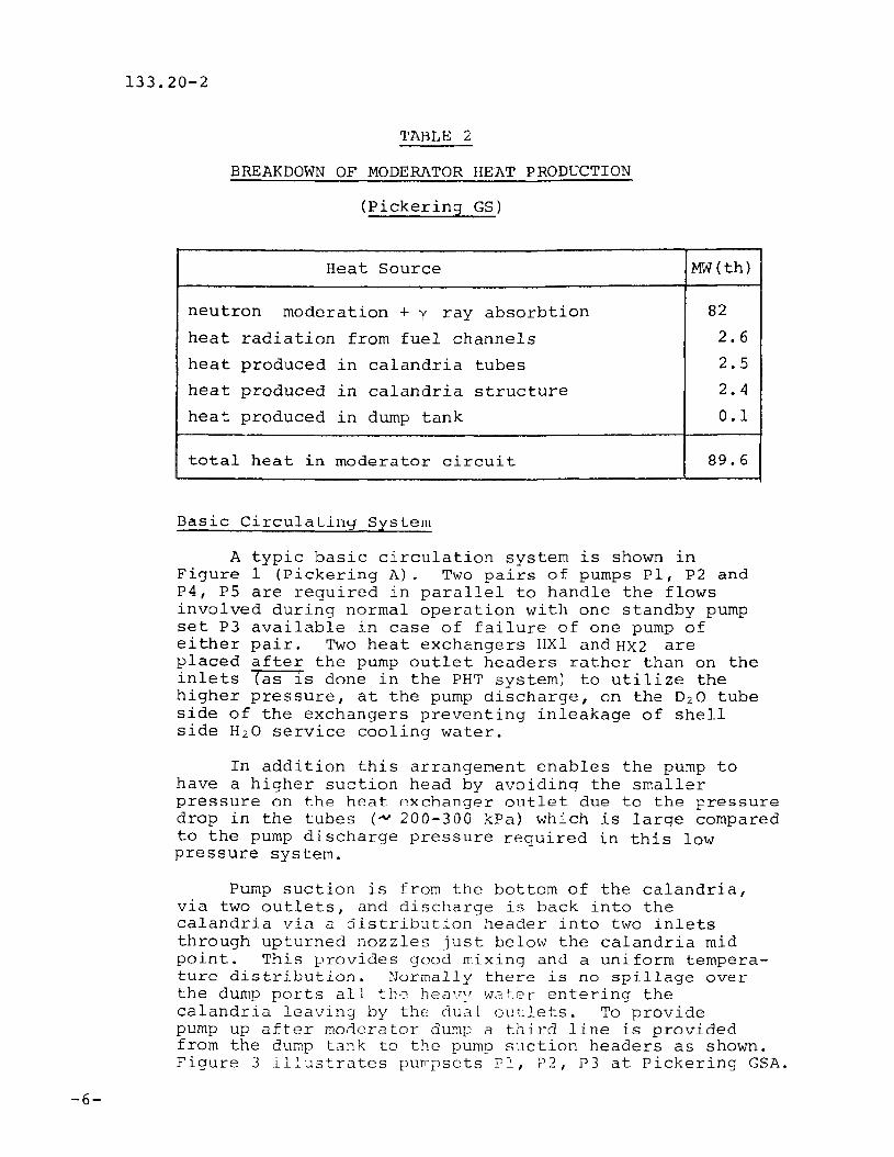
A pressure differential is established between thedump tank and the top of the calandria (Figure 4) bydrawing off a cover gas above the moderator in thecalandria, compressing it to about 180 kPa(a) andreturning it to the dump tank.
Gas compression is achieved using 2 x 100% blowersand moderator level control is obtained by controllingthe by passed cover gas leak rate through a set of 6control valves as shown.
For reactor trip a similar triplicated system of6 quick acting dump valves is used to short circuitthe pressure differential even when the blowers arepumping at full capacity.
Choice of Cover Gas
The cover gas used for the moderator system andalso in other systems where reactor grade heavy waterhas a liquid/gas interface is helium. The essentialproperties of a cover gas to perform this function are:
- low neutron capture cross section and hencea low induced activity.
- chemical inertness
- easily maintained purity.
- no radiolytic decomposition.
- reasonable cost.
Heliu~ satifies the above requirements better thanall other gases and is used exclusively in our stations.The main problem with helium as a cover gas is airinleakage at pressures below at~osphere which increasesthe nitrogen content. This would lead to the productionof nitric acid, with the presence of oxygen and yradiation from the core. ASI a result, the systempressure in the calandria is generally kept slightlyabove atmospheric.

133.20-2
COVER GAS SYSTEM EQUIP~lliNT
Helium Compressors
All the stations utilize two compressors, [calledblowers if the discharge pressure is less th~n 70 kP~
(g)] usually with rotary water type seals, one runningwith one on standby except during pump up. (Figure 4).
The seal water supply (D20) for the compressorsis taken from the main moderator distribution header,which being at the outlet of the heat exchangers iswhere the coolest water is available.
Gland leakage from the compressors is connectedto the moderator D20 collection system [section (h)].
Dump Valves and Control Valves
The six dump valves are large (- 30 em) butterflyvalves arranged in the usual safety system triplicatedmanner for (a) reliability and (b) maintenance requirements. If one channel fails to operate, the dump achievedby the remaining two channels opening the two series valves,in the line not influenced by the failed channel, is stillfast enough.
The six control valves are globe' valves, fourusually for coarse control and two for fine control.
Recombination Units
Two recombination units are usually provided,in parallel, for full flow operation in &eries withthe blowers, situated on the inlet to the blower••These units prevent the formation of an explolSivemixture of D2 and 02 gases in the cover ga5 whileat the same time preventing loss of D20. The unitscontain a palladium catalyst for the reaction and arealso provided with the following equipment and servicesfor their operation (Figure 4).
(i) heaters to start the chemical reactionand to dry out the units in case ofwaterlogging with D20.
(ii) H2 0 service water cooling used if th~
unit overheats.
(iii) flame arrestors are placed on the inletand outlet of each recombination unitto prevent the spread of an e~plosion
into the calandria or dump tank.
- 13

133.20-2
(iv)
(v)
a D?O moisture seDarator used on the recombiner inlet extracts water which thenbypasses the recombiner and is returnedto the blower suction.
gas chromatograph samplers situatedtypically upstream and downstream ofthe recombination units provide chemicalanalyses for D21 02 and N2 in the covergas.
-14-
Oxygen Addition
Provision is made to add oxygen, upstream of therecombination units if the cover gas composition showsan oxygen depletion. As a result of corrosion byoxygen the D2/02 ratio may be increased despite therecombination units and the oxygen addition then prevents excess deuterium build up.
Helium Storage and Addition
A helium storage tank is used to provide automatichelium bleed and feed to the cover gas system whenmoderator level is changing. Feed will usually be tothe blower suction and bleed from the blower dischargevia regulating and non return valv~s.
Provision is made also for the addition (manual)of helium to the storage tank from helium bottles.
The helium storage tank can also be used to s~ore
D 20 from the ca1andria if necessary and a tie line tothe calandria outlet lines is provided as shown. Inaddition use is made of this tank to store D 2 0 fromother D 2 0 auxiliary systems using a tie line into thebottom of the tank.
Pressure relief
Protection against overpressurizing must be provided for the major components of the cover gas system.
The calandria will usually have rupture discs (ordisc) on lines on top of the calandria as shown.
The dump tank will also be prutected by a reliefvalve situated/typically/close to the blower dischargeline into the dump tank.
Overpressurization of the cover gas system at theHe and O2 addition stations will be prevented by reliefvalves on these addition lines.

133.20-2
The helium storage tank is protected against overpressure by a safety relief valve and in addition will havea vacuum breaker arrangement, drawing in building air iftank pressure becomes subatmospheric.
Auxiliary Cover Gas System Connections
Helium can be used as a cover gas for other systemswhere reactor grade D2 0 has a liquid/gas interface forinstance to the moderator poison addition tank{s) and alsothe D20 collection system.
COVER GAS SYSTEMS FOR UNITS WITHOUT DUMP TANK
For units built after Pickering A moderator dump hasbeen abandoned. At Bruce A for instance this change hasmeant some modifications to the basic cover gas system.
One of these changes is that low discharge pressurehelium blowers are used and are of the diaphragm seal typethe system now requiring only sufficient pressure to circulatethe helium through the recombination units, from the top ofthe calandria, and directly back again.
The blowers require only H20 service water for coolingrather than the D20 seal water of the liquid ring type whichis advantageous as far as leakage is concerned.
The second change which is apparent at Bruce and will beon later units is the provision of a surge tank to suppresscalandria overpressurization on use of the liquid poisoninjection shutdown system which will be used on these units.
- 15 -

-16-
133.20-2
(c) LIQUID POISON ADDITION SYSTEM
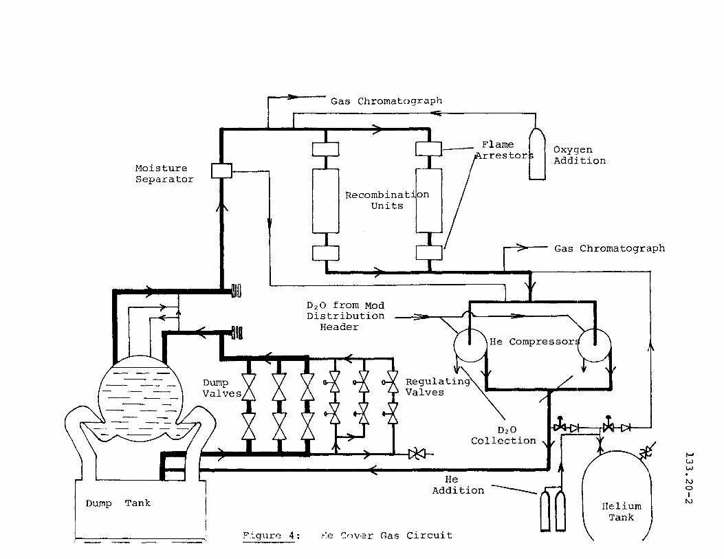
In all our stations, except NPD, boric acidsolution (or boric acid and gadolinium nitratesolutions) is added to the moderator main systemfor reactivity control. The solution is injectedinto the moderator distribution header as shownin Figure 5 (Pickering GSA) via a small bypassline.
Physically the boric acid (and/or gadoliniumnitrate is added to a mixing supply tank (ortanks» agitated to prevent coagulation and thenintroduc~d into the moderator by a small pump (orby gravity feed for better reliability) viaa needle valve and a powered globe valve indischarge line from the supply tank.
Helium will be used as a cover gas for themixing tank solution. A DzO supply delay tankis also provided to permit access to the mixingtank during operation by allowing N-16 and 0-19to decay.
(d) PURIFICATION SYSTEM
In general the moderator purification, ordemineralizer, system has several function:
1. to remove, or adjust the concentrationof boron and/or gadolinium in responseto reactivity demand.
2. to remove gadolinium after a poisoninjection shutdown (Bruce A andlarger units).
3. pD control to minimize corrosion ofthe system equipment.
4. corrosion product removal whichreduces the production of activatedcorrosion products and reduces radiolytic decomposition-oI DzO.
The equipment required for Band Gd removalis a number of IX columns, Figure 6, in parallel,valved into the moderator circulation system toallow convenient resin replacement.
133.20-2
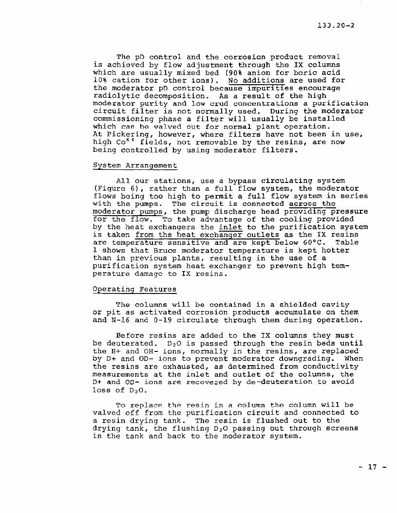
The pO control and the corrosion product removalis achieved by flow adjustment through the IX columnswhich are usually mixed bed (90% anion for boric acid10% cation for other ions). No additions are used forthe moderator pO control because impurities encourageradiolytic decomposition. As a result of the highmoderator purity and low crud concentrations a purificationcircuit filter is not normally used. During the moderatorcommissioning phase a filter will usually be installedwhich can be valved out for normal plant operation.At Pickering, however, where filters have not been in use,high Co 60 fields, not removable by the resins, are nowbeing controlled by using moderator filters.
System Arrangement
All our stations, use a bypass circulating system(Figure 6), rather than a full flow system, the moderatorflows being too high to permit a full flow system in serieswith the pumps. The circuit is connected across themoderator pumps, the pump discharge head providing pressurefor the flow. To take advantage of the cooling providedby the heat exchangers the inlet to the purification systemis taken from the heat exchanger outlets as the IX resinsare temperature sensitive and are kept below 60°C. Table1 shows that Bruce moderator temperature is kept hotterthan in previous plants, resulting in the use of apurification system heat exchanger to prevent high temperature damage to IX resins.
Operating Features
The columns will be contained in a shielded cavityor pit as activated corrosion products accumulate on themand N-16 and 0-19 circulate through them during operation.
Before resins are added to the IX columns they mustbe deuterated. D20 is passed through the resin beds untilthe H+ and OH- ions, normally in the resins, are replacedby 0+ and OD- ions to prevent moderator downgrading. Whenthe resins are exhausted, as determined from conductivitymeasurements at the inlet and outlet of the columns, the0+ and 00- ions are recovered by de-deuteration to avoidloss of D20.
To replace the resin in a column the column will bevalved off from the purification circuit and connected toa resin drying tank. The resin is flushed out to thedrying tank, the flushing D20 passing out through screensin the tank and back to the moderator system.
- 17 -

-18-
133.20-2
Auxiliary Moderator Systems
There are a number of secondary uses of themoderator system D20 where D20 in particular isrequired. Being a low temperature low pressuresystem it is easier to utilize than say D20 takenfrom the PHT system. Figure 7 illustrates thevarious take off lines to these systems, whichare now discussed.
(e) REACTIVITY MECHANISM COOL!NG
Heat is produced in adjuster rods, absorberrods, shut off rods flux monitor rods, and boosterrods during operation and during shutdown, due toneutron and y ray absorbtion as well as decay heatfrom activation. This heat must be removed toprevent damage from overheating as well as forsafety reasons for instance with boosters
Adjusters (Pickering A & B)
Cooling (~15 kW frod) during operation isachieved by utilizing a perforated'guide tube(Figure 3 section 10.2) for the rods so that thereis continual contact directly with the moderatorin the calandria. If the reactor is shutdownwith no moderator in the calandria a small coolingflow of D20 from a spray nozzle prevents the rodsfrom overheating. This cooling flow, taken offthe moderator system from the distribution headeris also adequate to provide sufficient cooling forthe rods if they are in the parked (or withdrawn)position during reactor operation.
Absorber rods and Booster rods (Douglas Point andBruce A & B)
The greater heat production in these rodsmeans that forced coolant circulation throughthe guide tubes is provided, the coolant thenforming part of the main ~oderator coolantcircuit, t:le boosters requiring~the largest anel.most reliable flow (- 3 MHfbooster rod versus- 25 kw/absorber rod at Douglas Point).
133.20-2
Shut Off Rods (Pickering A & larger stations
Being out of the core for most of their life a smallspray cooling supply is adequate for these rods. Heatproduction from activity build up in those rods will alsoDe much less than for absorbers or adjusters for the samereason.
Flux Monitor larger stations)
The in-core flux monitors now in use for neutronmonitoring and flux mapping may be cooled to prevent thedetectors from overheating and this is achieved by usingperforated zircaloy guide tubes inside which the detectors are located. Natural circulation of moderator D2 0through these tubes then provides adequate cooling. Inthe upper part of the guide tube, above the calandria, amoderator D20 spray cooling flow provides cooling for thedetector cables, and also for the detector when the moderator is dumped.
After PGSA however, no D20 spray cooling is beingprovided for the flux monitors as it is now thought notnecessary to cool the detector cables in the upper partof the guide tube.
(f) CALANDRIA, DUMP PORT AND DUMP TANK SPRAY COOLING
Heat is produced in the calandria vessel, dump portsand dlliup tank during reactor operation by neutron andgamma ray absorption and during shutdown by fission product radiation absorption. The cooling water will benistributed from spray headers being supplied from themoderator distribution header.
(g) EMERGENCY TRANSFER OF MODERATOR TO PHT SYSTEM
In Lhe event of a break in a. feeder pipe or a rupture of a main header, depressurizing the heat transportsystem, an emergency supply of cooling water is requiredto prevent the fuel from overheating. The most convenient and reliable source of water is from the moderator
- 19 -
133.20-2
system and so this is used for the emergency injectionwater as described in the section on heat transport system. Take off for this supply will be from the-moderatordistribution header.
Apart from this type of transfer from the moderatorto the PHT system, mixing D2 0 between these systems isgenerally considered undesirable for the following reasons:
- the T 3 activity is higher in the moderator
- the moderator pD is lower
- the moderator may contain BlOor Gd poison
- the isotopic will probably be slightly different.
Transfer between the two systems is available at NPDhowever, on a continuous basis, but this facility is nowavoided on the current reactors.
For reactors larger than Pickering however D20 injection for emergency cooling has given way to lightwater injection, the change being made primarily to enable the moderator to be used as a heat sink. For Brucethis light water comes by gravity feed £rom the vacuumbuilding dousing tank and for single unit stations fromthe reactor building H20 dousing tank.
(h) LEAKAGE COLLECTION
To prevent loss of costly and tritiated D2 0 from themoderator, provision has to be made to collect the heavywater from various leakage points in the system. Thesewould include pump seals and valve stem leakage pointswhich drain by gravity to a collection tank from whichthe collected water would be returned, after un isotopiccheck, to the moderator pump suction header, or to a drumfill station, if downgraded.
- 20 -

133.20-2
(i) DzO ADDITION AND TRANSFER
Provisions must be made for the addition of DzO tomake up for losses from the system by leakage or sampling.A moderator DzO drum addition station will be provided toadd heavy waLer to the collection tank from where it canbe pumped to the most convenient addition point, usuallythe moderator pump suction header.
Various DzO transfer lines will be provided to supply DzO to and from such facilities as the upgradingsystem(s), collection system and addition station.
ASSIGNMENT
1. Briefly summarize the basic requirements of the moderatorsystem.
2. (a) Why is it necessary to cool 'the moderator?
(b) Why can the heat removed not be put to some practical use?
(c) Why are the pumps and, sometimes, the heat exchangerduplicated?
3. What reasons exist for supplying a dump tank in themoderator system?
4. (a) Explain why a moderator puri fica tion system isrequired and why a by-pass system is used.
(b) What types of resin beds are used for what purposeand how is it known that the beds are exhausted?
5. (a) Why are spray cooling and booster and absorber rodr.onl ing r.()nnpct-inn~ rpCJ11ired?
(b) Give one reason why heavy water exchange should bepossible between the moderator and heat transportsystems and one reason why it is not desirable.
- 21 -

133.20-2
6. (a) What is the primary reason for having a cover gassystem and how is it fulfilled?
(b) What are the other possible uses of the cover gas?
~I • List the essential properties or the cover gas and ex
plain why helium is chosen.
8. Explain why a recombination circuit is necessary and whyis provision made on the recombination unit for bothheating and cooling.
D. Winfield
- 22 -
"
J
cu"
Tit =F J,e
@, !i I~!l
Cf' 11
'" ,,- 0<
6 rN !~ I...-I l
'"ii
L
I
~
0< " u c
133.20-2,I, 1 2! 3 ( 4 J. =-.:_~-=__==_:r=__:=~::::~=:..,__J ~-._._______ru..--~~_:~_" __.
A
c
D
?';r"
~='r.!,~$;
,.If:,~;~
"wr,.,••~"~!~~~~.
.. •"Jl'. :J,>,rt~'"
WE"sr FlMm. I"AU,r
I~~~~- C~~ts'//of
~--,.,-,--~-f~~p,i,;i~I"
'U"
Wi ~:"~',_,l., o. , -~,'0ISff!...4.•U U ~ ~-- Uj,'"
" ... ~ , -;g. iII-b-::..,.-~_~:-~, .. '-lllI'::1.'~' ro [lJi"tf'"fit " ~~. ,- _ •.ar~' ::.,
~
t~t- :~I't~ r-··~~t~~...-<,tI:'~, '::'4;:' "j"i'i~~
~ -'... r. o.:"'tJ,,'4.:
u. ,If:"""It-_~_-:r.~,..;x:._-'\;M~1 + I
lM\'.
o
~-6
>;-<e)----, ~"W~r-s~~ *:.ti
Il'C L-~~ ~
c
o
B
A
E
~.II ~I,~ .,. •~~~.~ .. ~CD ~
E •.
..........- <:r:tl:n......1'.., ...
"1).e-~ "
---_._-_._-_..•..._.. _. ..- - "--"'-'-' .- .--, 2' 3 ..i ~ .. ,_..i.~ .• _.~ _
F
''}~l~
:"Rt!;
"lJ L-,r-~::£fo~~,~'
z:~·
~., l'I~-
"::=f'";:'--,;~~ I!.'LL~J
l,->-s+:iPi';'';,J,i
~
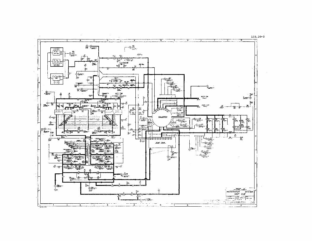
..... __.._- .--_.-: t __.~~~~~~~~_ t F!MODERATOR SYSrEM
~••••..-~~~ ~"!..E ~.__:..,~--" i,-'""-.f:",,,.--------.,' ·t:'~:~~)·~~:~~ __':~I:J


![Major Overhauling of Boiler and Auxiliaries of U 4[1]](https://static.fdocuments.net/doc/165x107/546f6a71b4af9fa1248b4600/major-overhauling-of-boiler-and-auxiliaries-of-u-41.jpg)