132 KV Grid Station Intern ship training report
28
1 InternShip Training Report 132 KV SubStation Kamalabad ,IESCO Submitted By: Muntazir Mehdi B.Sc Electrical Engineering 4 Th Year APCOMS affiliated with UET
-
Upload
muntazir-mehdi -
Category
Engineering
-
view
2.977 -
download
81
Transcript of 132 KV Grid Station Intern ship training report

1
InternShip Training Report132 KV SubStation Kamalabad ,IESCO
Training Duration: Two Weeks ( 20 Aug 2015 to 04 Sep 2015 )
Submitted By:
Muntazir Mehdi
B.Sc Electrical Engineering
4Th Year
APCOMS affiliated with UET Taxila
2
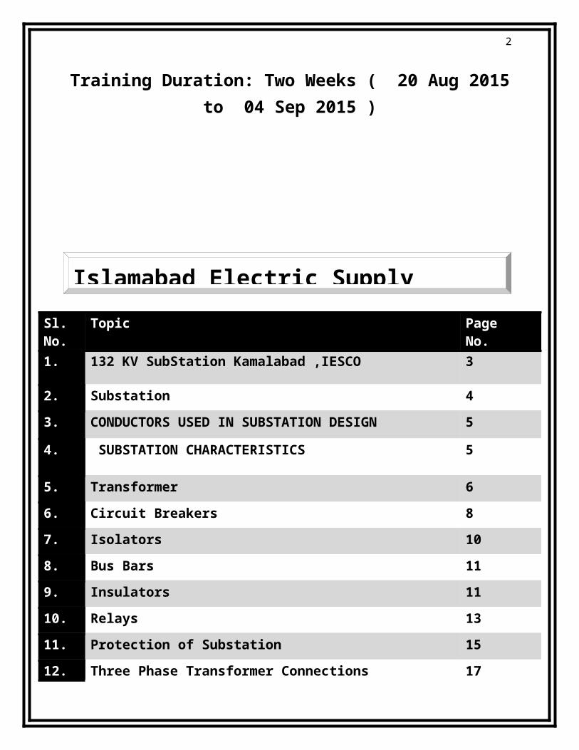
Sl.No.
Topic PageNo.
1. 132 KV SubStation Kamalabad ,IESCO 3
2. Substation 4
3. CONDUCTORS USED IN SUBSTATION DESIGN 5
4. SUBSTATION CHARACTERISTICS 5
5. Transformer 6
6. Circuit Breakers 8
7. Isolators 10
8. Bus Bars 11
9. Insulators 11
10. Relays 13
11. Protection of Substation 15
12. Three Phase Transformer Connections 17
13. Capacitor Bank 21
14. Conclusion 21
Islamabad Electric Supply

3
1. 132 KV SubStation Kamalabad ,IESCO
The 132 KV substation Kamalabad was commissioned in the year 1957.There are two main 132 KV bus incoming for the substation. These buses are:-1. 132 KV Rawat Line2. 132 KV Sandhani Line

4
2. SUBSTATION (Grid Stations)
Substation is an intermediate switching, transforming or converting station between the generating station and the low tension distribution network situated generally the consumer’s load centre.
The sub-station receives power from the generating station by a single or more feeders at a high voltage, transform the same to the different distribution voltages and sends to different consumers through distribution network.
Substations are classified by two broad categories:-
1. According to the service requirement:
Transformer substation
Switch substation
Power factor correction substation
Frequency change substation
Converting substation
Industrial substation
Collector Substation
Convertor Substation
Switching Substation
2. According to the constructional features:
Indoor substation
Outdoor substation
5
Underground substation
Pole mounted substation
3. CONDUCTORS USED IN SUBSTATION DESIGNAn ideal conductor should fulfill the following requirements:
a) Should be capable of carrying the specified load currents and short time currents. b) Should be able to withstand forces on it due to its situation. These forces comprise self-
weight, and weight of other conductors and equipment, short circuit forces and atmospheric forces such as wind and ice loading.
c) Should be corona free at rated voltage. d) Should have the minimum number of joints. e) Should need the minimum number of supporting insulators. f) Should be economical.
The most suitable material for the conductor system is copper or aluminums. Steel may be used but has limitations of poor conductivity and high susceptibility to corrosion. In an effort to make the conductor ideal, three different types have been utilized, and these include: Flat surfaced Conductors, Stranded Conductors, and Tubular Conductors.STANDARD SIZES OF CONDUCTOR FOR 132 KV LINES'Panther' ACSR having 7-strands of steel of dia 3.00 mm and 30-Strands of Aluminum of dia 3.00 mm.
4. SUBSTATION CHARACTERISTICS1. Each circuit is protected by its own circuit breaker and hence plant outage does not
necessarily result in loss of supply. 2. A fault on the feeder or transformer circuit breaker causes loss of the transformer and
feeder circuit, one of which may be restored after isolating the faulty circuit breaker. 3. A fault on the bus section circuit breaker causes complete shutdown of the substation.
All circuits may be restored after isolating the faulty circuit breaker. 4. Maintenance of a feeder or transformer circuit breaker involves loss of the circuit.

6
5. TRANSFORMERS
Transformer is a static machine, which transforms the potential of alternating current at same frequency. It means the transformer transforms the low voltage into high voltage & high voltage to low voltage at same frequency. It works on the principle of static induction principle.
When the energy is transformed into a higher voltage, the transformer is called step up transformer but in case of other is known as step down transformer.
TYPES OF TRANSFORMERS
1. Power Transformer
It is used for the transmission purpose at heavy load, high voltage greater than 33 KV & 100% efficiency. It also having a big in size as compare to distribution transformer, it used in generating station and Transmission substation at high insulation level. They can be of two types: Single Phase Transformers and Multi Phase Transformers.

7
2. Instrument Transformers
These transformers are used for the measurement purposes at that points where standard voltmeters and ammeters cannot be used. They are of two types:-
a). CURRENT TRANSFORMER
A current transformer (CT) is used for measurement of alternating electric currents. When current in a circuit is too high to apply directly to measuring instruments, a current transformer produces a reduced current accurately proportional to the current in the circuit, which can be conveniently connected to measuring and recording instruments. A current transformer isolates the measuring instruments from what may be very high voltage in the monitored circuit.

8
b).POTENTIAL OR VOLTAGE TRANSFORMER
Voltage transformers (VT) (also called potential transformers (PT)) are a parallel connected type of instrument transformer, used for metering and protection in high-voltage circuits or phasor phase shift isolation. They are designed to present negligible load to the supply being measured and to have an accurate voltage ratio to enable accurate metering. A potential transformer may have several secondary windings on the same core as a primary winding, for use in different metering or protection circuits.
3. On the basis of workingOn the above basis, transformers are of two types:
Step up Transformer Step down Transformer
4. Auto TransformersAn autotransformer is an electrical transformer with only one winding. The "auto" prefix refers to the single coil acting on itselfand not to any kind of automatic mechanism. In an autotransformer, portions of the same winding act as both the primary and secondary sides of the transformer. The winding has at least three taps where electrical connections are made. Autotransformers have the advantages of often being smaller, lighter,and cheaper than typical dual-winding transformers, but the disadvantage of not providing electrical isolation.
5. Distribution TransformersA distribution transformer is a transformer that provides the final voltage transmission in the electrical power distribution system, stepping down voltage to the level used by customers.

9
6. CIRCUIT BREAKERS
A circuit breaker is an automatically operated electrical switch designed to protect an electrical circuit from damage caused by overload or short circuit. Its basic function is to detect a fault condition and interrupt current flow. Unlike a fuse, which operates once and then must be replaced, a circuit breaker can be reset (either manually or automatically) to resume normal operation. Circuit breakers are made in varying sizes, from small devices that protect an individual household appliance up to large switchgear designed to protect high voltage circuits feeding an entire city. There are different types of circuit breakers which are:-
1.Low-voltage circuit breakersLow-voltage (less than 1,000 VAC) types are common in domestic, commercial and industrial application, and include Miniature Circuit Breaker (MCB) and Molded Case Circuit Breaker (MCCB).
2. Magnetic circuit breakersMagnetic circuit breakers use a solenoid (electromagnet) whose pulling force increases with the current. Certain designs utilize electromagnetic forces in addition to those of the solenoid.
3.Thermal magnetic circuit breakersThermal magnetic circuit breakers, which are the type found in most distribution boards, incorporate both techniques with the electromagnet responding instantaneously to large surges in current (short circuits) and the bimetallic strip responding to less extreme but longer-term over-current conditions. The thermal portion of the circuit breaker provides an "inverse time" response feature, which trips the circuit breaker sooner for larger over currents.
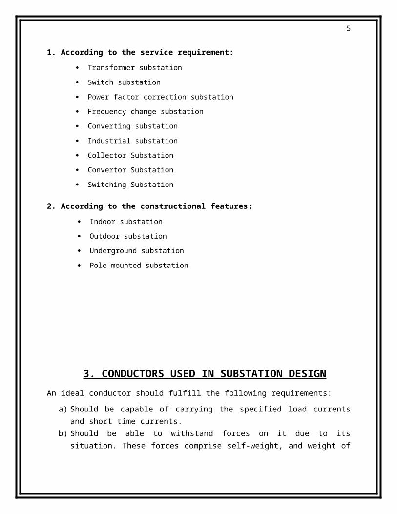
4.Common trip breakers

10
Three-pole common trip breaker for supplying a three-phase device. This breaker has a 2A rating. When supplying a branch circuit with more than one live conductor, each live conductor must be protected by a breaker pole. To ensure that all live conductors are interrupted when any pole trips, a "common trip" breaker must be used. These may either contain two or three tripping mechanisms within one case.
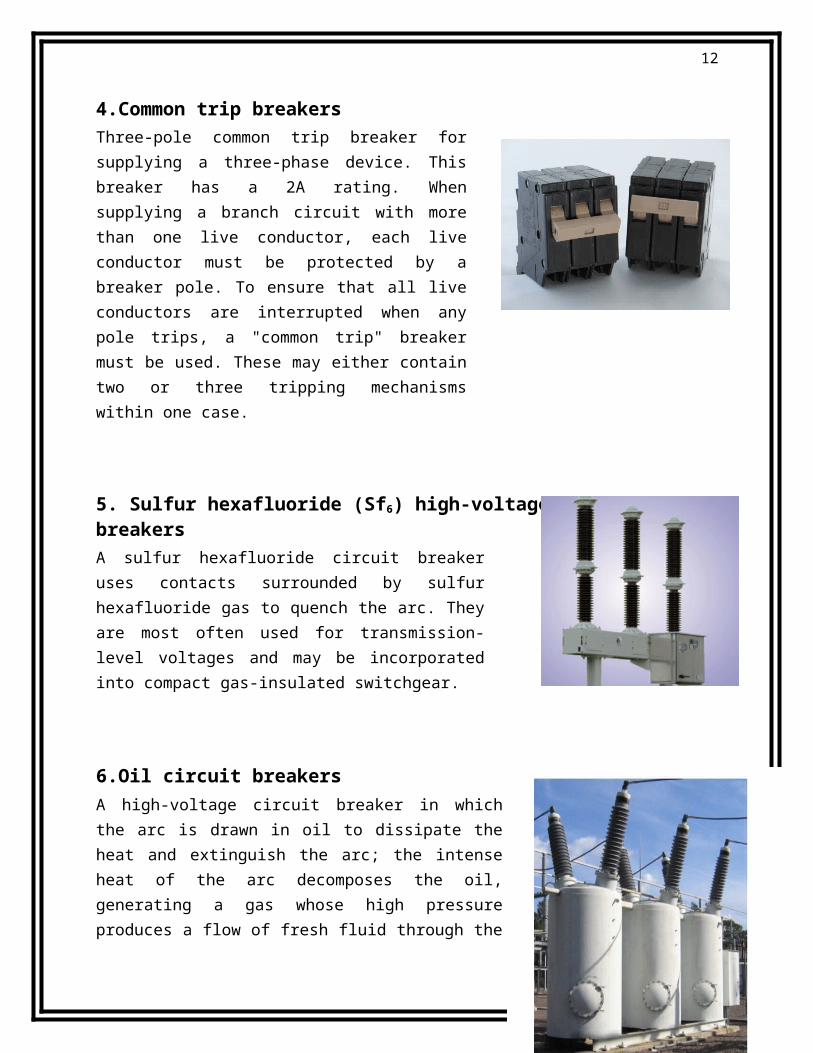
5. Sulfur hexafluoride (Sf6) high-voltage circuit breakersA sulfur hexafluoride circuit breaker uses contacts surrounded by sulfur hexafluoride gas to quench the arc. They are most often used for transmission-level voltages and may be incorporated into compact gas-insulated switchgear.
6.Oil circuit breakersA high-voltage circuit breaker in which the arc is drawn in oil to dissipate the heat and extinguish the arc; the intense heat of the arc decomposes the oil, generating a gas whose high pressure produces a flow of fresh fluid through the arc that furnishes the necessary insulation to prevent a restrike of the
arc.
The arc is then extinguished, both because of its elongation upon parting of contacts and because of intensive cooling by the gases and oil vapor. They are further of two types: Bulk Oil Circuit Breaker (BOCB) and Minimum Oil Circuit Breaker (MOCB).
7. Air circuit breakers
Rated current up to 6,300 A and higher for generator circuit breakers. Trip characteristics are often fully

11
adjustable including configurable trip thresholds and delays. Usually electronically controlled, though some modelsare microprocessor controlled via an integral electronic trip unit. Often used for main power distribution in large industrial plant, where the breakers are arranged in draw-out enclosures for ease of maintenance.
7. ISOLATERSIsolator can be rewritten as isolator is a manually operated mechanical switch which separates a part of the electrical power system normally at off load condition.
8. BUS BARS
When numbers of generators or feeders operating at the same voltage have to be directly connected electrically, bus bar is used as the common electrical component. Bus bars are made up of copper rods operate at constant voltage. The following are the important bus bars arrangements used at substations:
Single bus bar system Single bus bar system with section alisation. Duplicate bus bar system
12
9. INSULATORS
An electrical insulator is a material whose internal electric charges do not flow freely, and therefore make it very hard to conduct an electric current under the influence of an electric field. The insulator serves two purposes. They support the conductors (bus bar) and confine the current to the conductors. The most common used material for the manufacture of insulator is porcelain. There are several types of insulators
. Shackle insulator
In early days, the shackle insulators were used as strain insulators. But now a day, they are frequently used for low voltage distribution lines. Such insulators can be used either in a horizontal position or in a vertical
. Pin type insulator As the name suggests, the pin type insulator is mounted on a pin
on the cross-arm on the pole. There is a groove on the upper end of the insulator. The conductor passes through this groove and is tied to the insulator with annealed wire of the same material as the conductor. Pin type insulators are used for transmission and distribution of electric power at voltages up to 33 kV. Beyond

13
operating voltage of 33 kV, the pin type insulators become too bulky and hence uneconomical.
Suspension insulator For voltages greater than 33 kV, it is a usual practice to
use suspension type insulators shown in Figure. Consist of a number of porcelain discs connected in series by metal links in the form of a string. The conductor is suspended at the bottom end of this string while the other end of the string is secured to the cross-arm of the tower. The number of disc units used depends on the voltage.
. Strain insulator A dead end or anchor pole or tower is used where a straight section of line ends, or angles off in another direction. These poles must withstand the lateral (horizontal) tension of the long straight section of wire. In order to support this lateral load, strain insulators are used.
For low voltage lines (less than 11 kV), shackle insulators are used as strain insulators. However, for high voltage transmission lines, strings of cap-and-pin (disc) insulators are used, attached to the crossarm in a horizontal direction. When the tension load in lines is exceedingly high, such as at long river spans, two or more strings are used in parallel.
position. They can be directly fixed to the pole with a bolt or to the cross arm.
10. RELAYSIn a power system it is inevitable that immediately or later some failure does occur somewhere in the system. When a failure occurs on any part of the system, it must be quickly detected and disconnected from the system. Rapid disconnection of faulted apparatus limits the amount of damage to it and prevents the effects of fault from spreading into the system. For high voltage circuits relays are employed to serve the desired function of automatic protective gear. The relays detect the fault and supply the information to the circuit breaker.
The electrical quantities which may change under fault condition are voltage, frequency, current, phase angle. When a short circuit occurs at any point on the transmission line the current flowing in the line increases to the enormous value. This result in a heavy current flow through the relay coil, causing the relay to operate by closing its contacts. This in turn closes the

14
trip circuit of the breaker making the circuit breaker open and isolating the faulty section from the rest of the system. In this way, the relay ensures the safety of the circuit equipment from the damage and normal working of the healthy portion of the system.
Relay works on two main operating principles:-
Electromagnetic Attraction Electromagnetic Induction
RELAY USED IN CONTROLLING PANEL OF SUBSTATION
.Differential Relay
A differential relay is one that operates when vector difference of the two or more electrical quantities exceeds a predetermined value. If this differential quantity is equal or greater than the pickup value, the relay will operate and open the circuit breaker to isolate the faulty section.
. Over Current Relay
This type of relay works when current in the circuit exceeds the predetermined value. The actuating source is the current in the circuit supplied to the relay from a current transformer. These relay are used on A.C. circuit only and can operate for fault flow in the either direction. This relay operates when phase to phase fault occurs.
. Earth Fault Relay
This type of relay sense the fault between the lines and the earth. It checks the vector sum of all the line currents. If it is not equal to zero, it trips.
. Tripping Relay
This type of relay is in the conjunction with main relay. When

15
main relay sense any fault in the system, it immediately operates the trip relay to disconnect the faulty section from the section.
. Auxiliary Relay
An auxiliary relay is used to indicate the fault by glowing bulb or showing various flags.
11. PROTECTION OF SUBSTATION
LIGHTNING ARRESTORSA lightning arrestor is a device used in power systems and telecommunications systems to protect the insulation and conductors of the system from the damaging effects of lightning. The typical lightning arrester has a high-voltage terminal and a ground terminal. When a lightning surge (or switching surge, which is very similar) travels along the power line to the arrester, the current from the surge is diverted through the arrestor, in most cases to earth.

16
TRANSFORMER PROTECTIONTransformers are totally enclosed static devices and generally oil immersed. Therefore chances of fault occurring on them are very easy rare, however the consequences of even a rare fault may be very serious unless the transformer is quickly disconnected from the system. This provides adequate automatic protection for transformers against possible faults. Various protection methods used for transformers are:-
Buchholz Relay Buchholz relay is a safety device mounted on some oil-filled powertransformers and reactors, equipped with an external overhead oil reservoir called a conservator. The Buchholz Relay is used as a protective device sensitive to the effects of dielectric failure inside the equipment.Depending on the model, the relay has multiple methods to detect a failing transformer. On a slow accumulation of gas, due perhaps to slight overload, gas produced by decomposition of insulating oil accumulates in the top of the relay and forces the oil level down. A float switch in the relay is used to initiate an alarm signal. Depending on design, a second float may also serve to detect slow oil leaks.If an arc forms, gas accumulation is rapid, and oil flows rapidly into the conservator. This flow of oil operates a switch attached to a vane located in the path of the moving oil. This switch normally will operate a circuit breaker to isolate the apparatus before the fault causes additional damage
Conservator and Breather
When the oil expands or contacts by the change in the temperature, the oil level goes either up or down in main tank. A conservator is used to maintain the oil level up to predetermined value in the transformer main tank by placing it above the level of the top of the tank. Breather is connected to conservator tank for the purpose of extracting moisture as it spoils the insulating properties of the oil. During the contraction and expansion of oil air is drawn in or out through breather silica gel crystals impregnated with cobalt chloride. Silica gel is checked regularly and dried and replaced when necessary.

17
Marshalling box
It has two meter which indicate the temperature of the oil and winding of main tank. If temperature of oil or winding exceeds than specified value, relay operates to sound an alarm. If there is further increase in temperature then relay completes the trip circuit to open the circuit breaker controlling the transformer.
Transformer cooling
When the transformer is in operation heat is generated due to iron losses the removal of heat is called cooling.There are several types of cooling methods, they are as follows:
1. Air natural coolingIn a dry type of self-cooled transformers, the natural circulation of surrounding air is used for its cooling. This type of cooling is satisfactory for low voltage small transformers.
2. Air blast coolingIt is similar to that of dry type self-cooled transformers with to addition that continuous blast of filtered cool air is forced through the core and winding for better cooling. A fan produces the blast.
3. Oil natural coolingMedium and large rating transformers have their winding and core immersed in oil, which act both as a cooling medium and an insulating medium. The heat produce in the cores and winding is passed to the oil becomes lighter and rises to the top and place is taken by cool oil from the bottom of the cooling tank.
4. Oil blast coolingIn this type of cooling, forced air is directed over cooling elements of transformers immersed in oil.

18
5. Forced oil and forced air flow (OFB) coolingOil is circulated from the top of the transformers tank to a cooling tank to a cooling plant. Oil is then returned to the bottom of the tank.
6. Forced oil and water (OWF) coolingIn this type of cooling oil flow with water cooling of the oil in external water heat exchanger takes place. The water is circulated in cooling tubes in the heat exchanger.
12. Three Phase Transformer ConnectionsThree phase transformer connections In three phase system, the three phases can be connected in either star or delta configuration. In case you are not familiar with those configurations, study the following image which explains star and delta configuration. In any of these configurations, there will be a phase difference of 120° between any two phases.
Three Phase Transformer Connections
Windings of a three phase transformer can be connected in various configurations as (i) star-star, (ii) delta-delta, (iii) star-delta, (iv) delta-star, (v) open delta and (vi) Scott connection. These

19
configurations are explained below. Open Delta (V-V) ConnectionTwo transformers are used and primary and secondary connections are made as shown in the figure below. Open delta connection can be used when one of the transformers in Δ-Δ bank is disabled and the service is to be continued until the faulty transformer is repaired or replaced. It can also be used for small three phase loads where installation of full three transformer bank is un-necessary. The total load carrying capacity of open delta connection is 57.7% than that would be for delta-delta connection.
Star-Star (Y-Y)
Star-star connection is generally used for small, high-voltage transformers. Because of star connection, number of required turns/phase is reduced (as phase voltage in star connection is 1/√3 times of line voltage only). Thus, the amount of insulation required is also reduced.
The ratio of line voltages on the primary side and the secondary side is equal to the transformation ratio of the transformers.
Line voltages on both sides are in phase with each other. This connection can be used only if the connected load is balanced.
Delta-Delta (Δ-Δ)
This connection is generally used for large, low-voltage transformers. Number of required phase/turns is relatively greater than that for star-star connection.
The ratio of line voltages on the primary and the secondary side is equal to the transformation ratio of the transformers.
This connection can be used even for unbalanced loading. Another advantage of this type of connection is that even if one transformer is disabled,
system can continue to operate in open delta connection but with reduced available capacity.
Star-Delta OR Wye-Delta (Y-Δ)
The primary winding is star star (Y) connected with grounded neutral and the secondary winding is delta connected.
This connection is mainly used in step down transformer at the substation end of the transmission line.
The ratio of secondary to primary line voltage is 1/√3 times the transformation ratio. There is 30° shift between the primary and secondary line voltages.

20
Delta-Star OR Delta-Wye (Δ-Y)
The primary winding is connected in delta and the secondary winding is connected in star with neutral grounded. Thus it can be used to provide 3-phase 4-wire service.
This type of connection is mainly used in step-up transformer at the beginning of transmission line.
The ratio of secodary to primary line voltage is √3 times the transformation ratio. There is 30° shift between the primary and secondary line voltages.
Above transformer connection configurations are shown in the following figure.

21
13. CAPACITOR BANK

22
The load on the power system is varying being high during morning and evening which increases the magnetization current. This result in the decreased power factor. The low power factor is mainly due to the fact most of the power loads are inductive and therefore take lagging currents. The low power factor is highly undesirable as it causes increases in current, resulting in additional losses. So in order to ensure most favorable conditions for a supply system from engineering and economic stand point it is important to have power factor as close to unity as possible. In order to improve the power factor come device taking leading power should be connected in parallel with the load. One of such device can be capacitor bank. The capacitors draw a leading current and partly or completely neutralize the lagging reactive component of load current.
Main functions of Capacitor Bank are:- Supply Reactive Power Improve Terminal Voltage Improve Power Factor
14. CONCLUSION
Now from this report one can conclude that electricity plays an important role in our life. That’s why various protective measures are taken to protect the substations from various faults and its smooth functioning. At the end of the training, I came to know about the various parts of substations and how they are operated