1310625261_52__14.pdf
5
Power Transmission Schaberweg 30-34 61348 Bad Homburg Germany Telephone +49 6172 275-0 Telefax +49 6172 275-275 www.ringspann.com [email protected] Installation and Operating Instructions for RLK 350 Cone Clamping Elements E 03.606e
-
Upload
barukomkss -
Category
Documents
-
view
213 -
download
1
Transcript of 1310625261_52__14.pdf
Power Transmission
Schaberweg 30-34 61348 Bad Homburg Germany
Telephone +49 6172 275-0 Telefax +49 6172 275-275
www.ringspann.com [email protected]
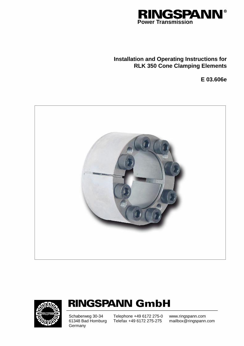
Installation and Operating Instructions for RLK 350 Cone Clamping Elements
E 03.606e

Installation and Operating Instructions for RLK 350 Cone Clamping Elements E 3.606 e
Date: 21.05.2010 Version : 03 signed: Su reviewed: Ei Pages: 5 Page: 2
IMPORTANT
Please read these instructions carefully before installing and operating the product. Your particular attention is drawn to the notes on safety. These installation and operating instructions are valid on condition that the product meets the selection criteria for its proper use. Selection and design of the product is not the subject of these installtion and operating instructions. Disregarding or misinterpreting these installation and operating instructions invalidates any product liability or warranty by RINGSPANN; the same applies if the product is taken apart or changed. These installation and operating instructions should be kept in a safe place and should accompany the product if it is passed on to others -either on its own or as part of a machine- to make it accessible to the user.
SAFETY NOTICE
• Installation and operation of this product should only be carried out by skilled personnel.
• Repairs may only be carried out by the manufacturer or accredited RINGSPANN agents.
• If a malfunction is indicated, the product or the machine into which it is installed, should be
stopped immediately and either RINGSPANN or an accredited RINGSPANN agent should be informed.
• Switch off the power supply before commencing work on electrical components. • Rotating machine elements must be protected by the purchaser to prevent accidental contact. • Supplies abroad are subject to the safety laws prevailing in those countries.
Installation and Operating Instructions for RLK 350 Cone Clamping Elements E 3.606 e
Date: 21.05.2010 Version : 03 signed: Su reviewed: Ei Pages: 5 Page: 3
1. General information
1.1 Function:
RLK 350 Cone Clamping Elements are internal clamping connections for backlash free fastening of hubs on shafts. By tightening clamping screws surfaces are pulled together generating radial forces; these forces create a frictional connection between the Cone Clamping Element and the shaft as well as the hub. Torques or axial forces can be transmitted from the shaft via the Cone Clamping Element to the hub.
1.2 General safety instructions:
Caution! Danger of injury! The immediate vicinity of the rotating shrink disc must be kept clear of body parts, hair, clothing and other objects at all times.
2. Configuration and function
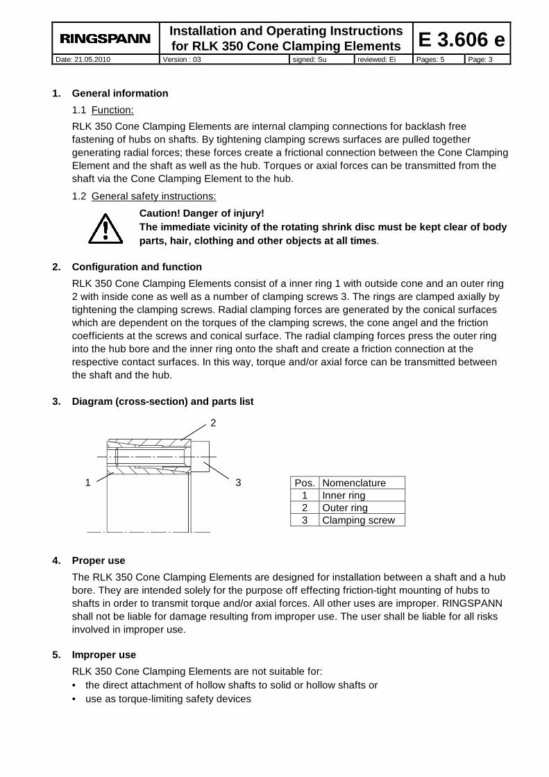
RLK 350 Cone Clamping Elements consist of a inner ring 1 with outside cone and an outer ring 2 with inside cone as well as a number of clamping screws 3. The rings are clamped axially by tightening the clamping screws. Radial clamping forces are generated by the conical surfaces which are dependent on the torques of the clamping screws, the cone angel and the friction coefficients at the screws and conical surface. The radial clamping forces press the outer ring into the hub bore and the inner ring onto the shaft and create a friction connection at the respective contact surfaces. In this way, torque and/or axial force can be transmitted between the shaft and the hub.
3. Diagram (cross-section) and parts list 4. Proper use
The RLK 350 Cone Clamping Elements are designed for installation between a shaft and a hub bore. They are intended solely for the purpose off effecting friction-tight mounting of hubs to shafts in order to transmit torque and/or axial forces. All other uses are improper. RINGSPANN shall not be liable for damage resulting from improper use. The user shall be liable for all risks involved in improper use.
5. Improper use
RLK 350 Cone Clamping Elements are not suitable for: • the direct attachment of hollow shafts to solid or hollow shafts or • use as torque-limiting safety devices
Pos. Nomenclature 1 Inner ring 2 Outer ring 3 Clamping screw
1
2
3
Installation and Operating Instructions for RLK 350 Cone Clamping Elements E 3.606 e
Date: 21.05.2010 Version : 03 signed: Su reviewed: Ei Pages: 5 Page: 4
6. Condition on delivery
The cone clamping elements are delivered packed in special paper to protect against corrosion. 7. Technical requirements for safe and effective operation
In order to achieve full transmission of torque and/or axial forces, tolerance on contact-pressure surfaces
• may not exceed tolerance class h8 for shafts
• or tolerance class H8 for hub bores.
In addition, pressure-contact surfaces on shafts and hubs must have a mean peak-to-valley height Ra < 3,2 µm.
Shaft and hub must be manufactured from materials with the following mechanical properties: • E-module about 170 kN/mm2
Regarding fixed hubs the values for M, F, PW and PN shown in the catalogue have to be reduced by 37%, possibly resulting in a reduced value for Kmin.
8. Mounting
8.1 Clean all contact surfaces on the shaft and hub thoroughly.
8.2 Apply a light coat of oil to the cone clamping element.
Do not use oil containing molybdenum sulphide or high-pressure additives or grease of any kind!
8.3 Loosen the clamping screws by several revolutions by hand in a crosswise sequence.
8.4 Remove a number of clamping screws matching the number of threaded press-off bores and insert them into the threaded press-off bores, turning to the point at which the inner and outer rings are held apart.
8.5 Insert the cone clamping element in the part to be clamped and push it onto the shaft.
8.6 Remove the screws from the press-off bores and insert them into the threaded clamping bores again.
8.7 Tighten the screws by hand in a crosswise sequence, aligning the shaft in the process.
8.8 Tighten the clamping screws to half the specified tightening torque Ms with a torque wrench spanner (see Section 11). Then tighten clockwise with half the tightening torque Ms.
8.9 Tighten the clamping screws clockwise several times with full torque.
The tightening process is ended with no screw turns when retightened with a torque of Ms. Missing or damaged clamping screws must be replaced with identical screws of quality grade 12.9!
9. Dismantling
9.1 Loosen the screws by several revolutions.
9.2 Remove a number of clamping screws matching the number of threaded press-off bores and insert them into the threaded press-off bores.
Installation and Operating Instructions for RLK 350 Cone Clamping Elements E 3.606 e
Date: 21.05.2010 Version : 03 signed: Su reviewed: Ei Pages: 5 Page: 5
9.3 Tighten the screws in the threaded press-off bores uniformly in increments of ½ revolution. This separates the outer ring from the inner ring and releases the connection.
9.4 Remove the hub and the cone clamping element from the shaft.
9.5 Dismantle the cone clamping element and clean thoroughly.
9.6 Inspect the cone clamping element for damage.
Only undamaged cone clamping elements may be reused!
9.7 When working with reusable cone clamping elements, lubricate all contact surfaces, the threads on the clamping screws and the contact surfaces of the screw head with a light coat of oil.
Do not use oil containing molybdenum sulphide or high-pressure additives or grease of any kind.
10. Maintenance
RLK 350 Cone Clamping Elements are maintenance-free. However, signs of settling may appear in connections during operation. We therefore recommend checking the tightness of the clamping screws each time maintenance is performed on the machine.
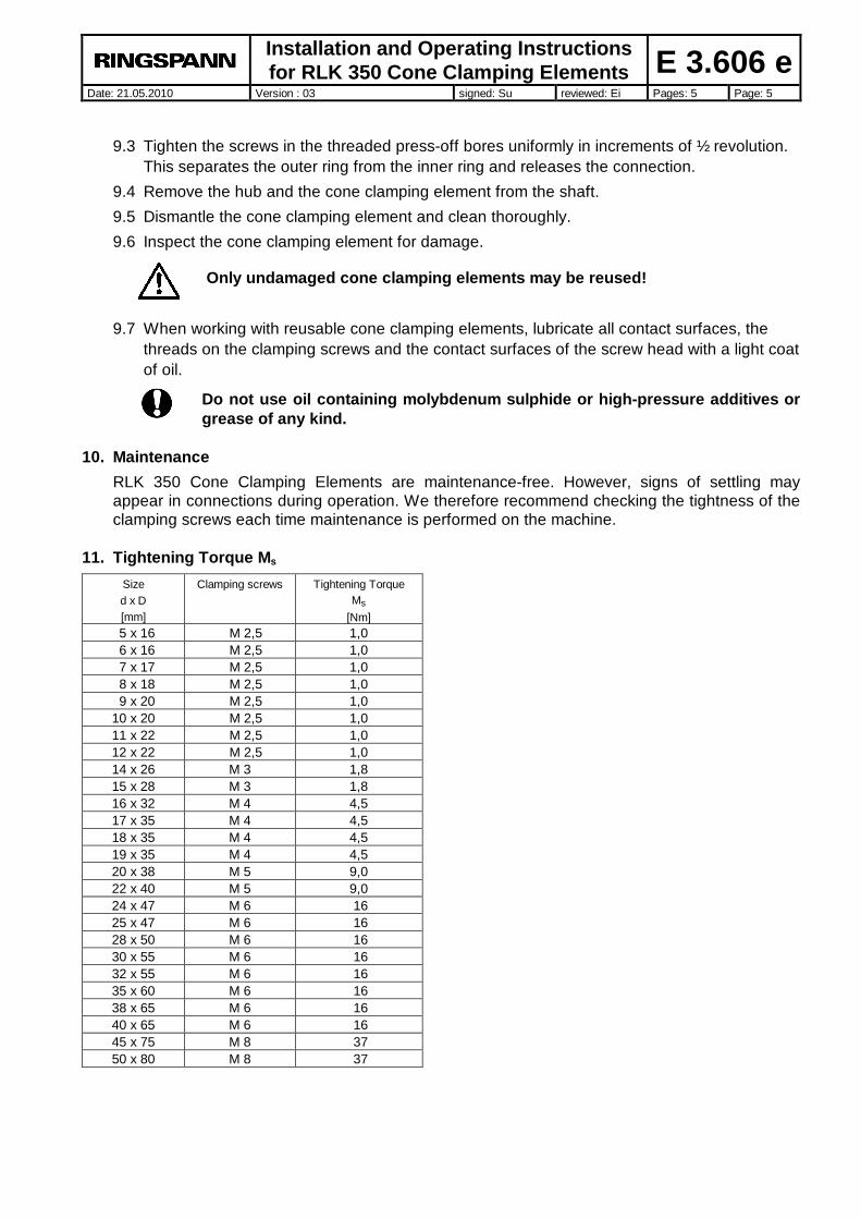
11. Tightening Torque Ms
Size d x D [mm]
Clamping screws Tightening Torque Ms
[Nm] 5 x 16 M 2,5 1,0 6 x 16 M 2,5 1,0 7 x 17 M 2,5 1,0 8 x 18 M 2,5 1,0 9 x 20 M 2,5 1,0 10 x 20 M 2,5 1,0 11 x 22 M 2,5 1,0 12 x 22 M 2,5 1,0 14 x 26 M 3 1,8 15 x 28 M 3 1,8 16 x 32 M 4 4,5 17 x 35 M 4 4,5 18 x 35 M 4 4,5 19 x 35 M 4 4,5 20 x 38 M 5 9,0 22 x 40 M 5 9,0 24 x 47 M 6 16 25 x 47 M 6 16 28 x 50 M 6 16 30 x 55 M 6 16 32 x 55 M 6 16 35 x 60 M 6 16 38 x 65 M 6 16 40 x 65 M 6 16 45 x 75 M 8 37 50 x 80 M 8 37