13. VEIN STRUCTURES AND THEIR TECTONIC IMPLICATIONS … · VEIN STRUCTURES AND THEIR TECTONIC...
13
Taylor, B., Fujioka, K., et al., 1992 Proceedings of the Ocean Drilling Program, Scientific Results, Vol. 126 13. VEIN STRUCTURES AND THEIR TECTONIC IMPLICATIONS FOR THE DEVELOPMENT OF THE IZU-BONIN FOREARC, LEG 126 1 Y. Ogawa, 2 J. Ashi, 3 and K. Fujioka 3,4 ABSTRACT Samples with vein structures were taken from Sites 787 and 793 in the forearc basin of the Izu-Bonin island arc off Aoga Shima and Sumisu Jima, respectively, between the present volcanic front and the outer arc high. The samples were studied by thin section, X-ray radiograph, and magnetometer; they are discussed with respect to the tectonic implication of the vein structures to the island-arc development. Vein structures are developed in finer, more clayey, preferentially radiolarian-bearing mudstone, subvertical to the bedding plane, which is mostly horizontal. The veins are restricted to certain horizons: in the upper Oligocene at Site 787 and in the lower Miocene at Site 793. The veins are filled with a dominant clay mineral (montmorillonite), which flowed into the vein when the fracture and concomitant stress drop occurred. Some clay mineral was deposited from the fluid that invaded the vein. Some veins might have occurred as hydraulic fractures. The shape, mode of occurrence, and other structural features indicate that the veins originated either as extension fractures or shear cleavages, and then were rotated by the following shearing parallel to the bedding. Sometimes the bedding-parallel slip planes are dislocated by the veins, and sometimes vice versa. This suggests that the vein formation and bedding parallel slip alternately occurred within the same stress environment. Vein attitude was measured by a magnetometer, after alternating field demagnetization; we interpret that they originally formed as subvertical planes, the trends of which average to N45W. The quantity of samples studied was small, but the trends suggest that the stress field for veining might have had a relative extensional stress axis that lay subhorizontally and trended generally northeast. This stress orientation might be attributed to either bending or normal faulting in the forearc basin, at a time when the arc trended northwest. INTRODUCTION "Vein structure" is sporadically seen in compacted mudstones as an array of mud veins (Ogawa, 1980; Cowan, 1982; Ogawa and Miyata, 1985; Helm and Vollbrecht, 1985; Knipe, 1986; Lundberg and Moore, 1986; Brown and Behrmann, 1990). Each mud vein is 100 μm to 1 mm in width and 1 cm in length in cross section, but they continue considerably longer in the third dimension. Veins are closely spaced at 1 -mm intervals to make a specific structure in an array. Some veins often show a sigmoidal shape (Cowan, 1982) but not always. There are many variations of the shape of each vein and sets of veins, and they are classified in several ways, as in figure 3 of Ogawa and Miyata (1985). The basic type of vein, however, is a fish style. This structure has long been recognized on land in central Japan, but only recently has it been described in detail by Ogawa (1980) from the Miura-Boso peninsulas, central Honshu, which corresponds to the northern extension of the Izu-Bonin forearc. Many examples have been cited by Deep Sea Drilling Project (DSDP) drilling in the area, particularly on Legs 57 and 87 in the Japan Trench landward slope (Arthur et al, 1980; Leggett et al., 1987), and on Legs 67 and 84 in the Middle America Trench landward slope off Guatemala (Cowan, 1982; Ogawa and Miyata, 1985). Most of those examples are known from the trench-landward slopes of nonaccretion-type convergent margins, that is, the veins favor the trench-slope covers. Beside these examples, some cases have been found in backarc settings or in 1 Taylor, B., Fujioka, K., et al., 1992. Proc. ODP, Sci. Results, 126: College Station, TX (Ocean Drilling Program). 2 Department of Earth and Planetary Sciences, Kyushu University, 33 Hakozaki, Fukuoka 812, Japan. 3 Ocean Research Institute, University of Tokyo, 1-15-1 Minamidai, Nakano, Tokyo 164, Japan. 4 Present address: Japan Marine Science and Technology Center, 2-14 Natsushima, Yokosuka, Kanagowa 238, Japan. accretionary prisms, all of which are involved within a horizontal stretching regime, as will be discussed later. The examples described and discussed in this paper were taken from the forearc setting of the Izu-Bonin (Ogasawara) Arc during drilling at Ocean Drilling Program (ODP) Sites 787 and 793 (Fig. 1). Other sites, such as 788, 789, 790, 791, and 792, did not yield any vein structures. Site 784, just on the foot of the serpentine diapir mound on the more trenchward slope of the Izu-Bonin Arc, has examples of vein structures within Pleistocene and Miocene sections (Shipboard Scientific Party, 1990). However, the vein horizons tend to be restricted to mostly Oligocene to Miocene levels. The restricted sites and horizons may be a result of tectonic settings and lithologies that depend largely upon age; although the critical horizons differ between Sites 787 and 793, the latter contains more radiolarians. In these cases, the critical lithologies seem to be either radiolarian or vitric claystone or mudstone, or just claystone. No coarse sediments, such as sandstone or coarse tuffaceous rocks, have any vein structures. Our examples, therefore, have definite sedimentary and tectonic significance for the development of the Izu-Bonin island arc. To determine this significance, we must first describe their occurrence and note the vein attitude using a magnetometer; we will then discuss the origin and related tectonic implication of the vein structures in the context of island-arc development. METHODS Samples were taken with a 25-cm 3 plastic tube onboard the JOIDES Resolution. Arrows indicate the vertical upward direction. The X, Y, and Z abscissa were set as in Figure 2. X-ray radiographs of thinned slices of the core samples on an X-Z plane and ordinary pictures were taken onshore (Fig. 3). Thin sections were made of the same position for X-ray radiographs. Some of the samples were so soft from desiccation that treatments of any kind could not be undertaken. The samples were then treated with a magnetometer to determine the original attitude of the veins according to the methods described below. 195
Transcript of 13. VEIN STRUCTURES AND THEIR TECTONIC IMPLICATIONS … · VEIN STRUCTURES AND THEIR TECTONIC...

Taylor, B., Fujioka, K., et al., 1992Proceedings of the Ocean Drilling Program, Scientific Results, Vol. 126
13. VEIN STRUCTURES AND THEIR TECTONIC IMPLICATIONS FOR THE DEVELOPMENTOF THE IZU-BONIN FOREARC, LEG 1261
Y. Ogawa,2 J. Ashi,3 and K. Fujioka3,4
ABSTRACT
Samples with vein structures were taken from Sites 787 and 793 in the forearc basin of the Izu-Bonin island arc off AogaShima and Sumisu Jima, respectively, between the present volcanic front and the outer arc high. The samples were studied bythin section, X-ray radiograph, and magnetometer; they are discussed with respect to the tectonic implication of the vein structuresto the island-arc development.
Vein structures are developed in finer, more clayey, preferentially radiolarian-bearing mudstone, subvertical to the beddingplane, which is mostly horizontal. The veins are restricted to certain horizons: in the upper Oligocene at Site 787 and in the lowerMiocene at Site 793. The veins are filled with a dominant clay mineral (montmorillonite), which flowed into the vein when thefracture and concomitant stress drop occurred. Some clay mineral was deposited from the fluid that invaded the vein. Some veinsmight have occurred as hydraulic fractures. The shape, mode of occurrence, and other structural features indicate that the veinsoriginated either as extension fractures or shear cleavages, and then were rotated by the following shearing parallel to the bedding.Sometimes the bedding-parallel slip planes are dislocated by the veins, and sometimes vice versa. This suggests that the veinformation and bedding parallel slip alternately occurred within the same stress environment.
Vein attitude was measured by a magnetometer, after alternating field demagnetization; we interpret that they originally formedas subvertical planes, the trends of which average to N45W. The quantity of samples studied was small, but the trends suggestthat the stress field for veining might have had a relative extensional stress axis that lay subhorizontally and trended generallynortheast. This stress orientation might be attributed to either bending or normal faulting in the forearc basin, at a time when thearc trended northwest.
INTRODUCTION
"Vein structure" is sporadically seen in compacted mudstones asan array of mud veins (Ogawa, 1980; Cowan, 1982; Ogawa andMiyata, 1985; Helm and Vollbrecht, 1985; Knipe, 1986; Lundbergand Moore, 1986; Brown and Behrmann, 1990). Each mud vein is100 µm to 1 mm in width and 1 cm in length in cross section, but theycontinue considerably longer in the third dimension. Veins are closelyspaced at 1 -mm intervals to make a specific structure in an array. Someveins often show a sigmoidal shape (Cowan, 1982) but not always.There are many variations of the shape of each vein and sets of veins,and they are classified in several ways, as in figure 3 of Ogawa andMiyata (1985). The basic type of vein, however, is a fish style.
This structure has long been recognized on land in central Japan,but only recently has it been described in detail by Ogawa (1980) fromthe Miura-Boso peninsulas, central Honshu, which corresponds to thenorthern extension of the Izu-Bonin forearc. Many examples havebeen cited by Deep Sea Drilling Project (DSDP) drilling in the area,particularly on Legs 57 and 87 in the Japan Trench landward slope(Arthur et al, 1980; Leggett et al., 1987), and on Legs 67 and 84 inthe Middle America Trench landward slope off Guatemala (Cowan,1982; Ogawa and Miyata, 1985). Most of those examples are knownfrom the trench-landward slopes of nonaccretion-type convergentmargins, that is, the veins favor the trench-slope covers. Beside theseexamples, some cases have been found in backarc settings or in
1 Taylor, B., Fujioka, K., et al., 1992. Proc. ODP, Sci. Results, 126: College Station,TX (Ocean Drilling Program).
2 Department of Earth and Planetary Sciences, Kyushu University, 33 Hakozaki,Fukuoka 812, Japan.
3 Ocean Research Institute, University of Tokyo, 1-15-1 Minamidai, Nakano, Tokyo164, Japan.
4 Present address: Japan Marine Science and Technology Center, 2-14 Natsushima,Yokosuka, Kanagowa 238, Japan.
accretionary prisms, all of which are involved within a horizontalstretching regime, as will be discussed later.
The examples described and discussed in this paper were takenfrom the forearc setting of the Izu-Bonin (Ogasawara) Arc duringdrilling at Ocean Drilling Program (ODP) Sites 787 and 793 (Fig. 1).Other sites, such as 788, 789, 790, 791, and 792, did not yield anyvein structures. Site 784, just on the foot of the serpentine diapirmound on the more trenchward slope of the Izu-Bonin Arc, hasexamples of vein structures within Pleistocene and Miocene sections(Shipboard Scientific Party, 1990). However, the vein horizons tendto be restricted to mostly Oligocene to Miocene levels. The restrictedsites and horizons may be a result of tectonic settings and lithologiesthat depend largely upon age; although the critical horizons differbetween Sites 787 and 793, the latter contains more radiolarians. Inthese cases, the critical lithologies seem to be either radiolarian orvitric claystone or mudstone, or just claystone. No coarse sediments,such as sandstone or coarse tuffaceous rocks, have any vein structures.
Our examples, therefore, have definite sedimentary and tectonicsignificance for the development of the Izu-Bonin island arc. Todetermine this significance, we must first describe their occurrenceand note the vein attitude using a magnetometer; we will then discussthe origin and related tectonic implication of the vein structures in thecontext of island-arc development.
METHODS
Samples were taken with a 25-cm3 plastic tube onboard the JOIDESResolution. Arrows indicate the vertical upward direction. The X, Y, andZ abscissa were set as in Figure 2. X-ray radiographs of thinned slices ofthe core samples on an X-Z plane and ordinary pictures were takenonshore (Fig. 3). Thin sections were made of the same position for X-rayradiographs. Some of the samples were so soft from desiccation thattreatments of any kind could not be undertaken. The samples were thentreated with a magnetometer to determine the original attitude of the veinsaccording to the methods described below.
195

Y. OGAWA, J. ASHI, K. FUJIOKA
138° 140° 142°36°N
Working half
140° 142°
B
40 80Distance (km)
120
Figure 1. A. Index map for sample location. Topmost arrow shows the Miura (M)and Boso (B) peninsulas, central Honshu. B. Schematic section of the Izu-Bonin Arc with locations of Sites 787, 792, and 793. OAH = outer-arc high,FB = forearc basin, and FAH = forearc high.
DESCRIPTION OF THE VEIN STRUCTURES
General Description
Site 787
Site 787 is located at 112 km outward from the volcanic front,Aoga Shima (Aogashima Island), and inward of the outer-arc high(Figs. 1 and 4). According to the seismic section (Taylor, Fujioka, et
Core "up"
Figure 2. Sample direction (X and Y) and abscissa (Z) in the working half of core.
al., 1990, pp. 407-413), the surface of the forearc basin dips seawardat 1.6°. The Oligocene to Holocene strata and the Miocene andPliocene unconformities abut toward the east upon the Eocene outer-arc high. Strata are normally faulted through the upper section,suggesting that horizontal west-east stretching has occurred ratherrecently. Thus, the present forearc is known as a failed rift, which wasformed for a short period during the early Oligocene (Taylor, Fujioka,et al., 1990, pp. 66-96).
The site was drilled to about 320 m below the seafloor (mbsf) tothe upper Oligocene. Only very thin Miocene and Pliocene sectionswere recovered, probably because of erosion in the old canyon. TheOligocene strata are normally faulted. Most of the samples that showvein structures are radiolarian-bearing, tuffaceous mudstone or claystone,but they are not as radiolarian-dominant as the samples from Site 793described below.
Sample 126-787B-9R-1, 11-13 cm, has spaced thin veins of abraided type within bioturbated mudstone. Bedding is horizontal, andveins are almost vertical (Fig. 3B-1). The veins cut and dislocate thetrace fossils, suggesting a small displacement in a normal fault sense.Sample 126-787B-11R-3, 21-23 cm, has a braided type of vein inreddish mudstone (Fig. 3A-2). In this case, the general trend of thevein is steep to the bedding, which is horizontal. Sample 126-787B-21R-3, 37-38 cm, has and irregular, but braided vein type with aclastic dyke (Fig. 3A-3). These three examples are all from the upperOligocene strata. The development of the veins is not so remarkableat Site 787; they are more or less irregular and scarce.
Sue 793
Site 793 is located at about 58 km outward from the volcanic front,east-southeast of Sumisu Jima (Sumisu Island) (Figs. 1 and 4). In thenorth-south seismic section, the strata are almost horizontal, but inthe west-east section the surface of the slope dips seaward at about0.72°. The strata are associated with scarce undulations and smallscale displacement normal faults (Taylor, Fujioka, et al., 1990, pp.407-413).
A 172-m-thick middle and lower Miocene unit was drilled afterdrilling without coring from 100 to 580 mbsf. Below this, a 645-m-thick upper and lower Oligocene sequence was drilled above thelower Oligocene andesitic pyroclastic and lava rocks. Most of theOligocene sections are volcaniclastic rock, whereas the Miocenesection is less tuffaceous and muddy or rather clayey. Mud veinstructures were observed only in the Miocene sections, particularlyin the silty claystone, commonly in radiolarian-rich claystone from
196

VEIN STRUCTURES AND THEIR TECTONIC IMPLICATIONS
2 cm
B
2 cm
Figure 3. A. X-ray radiographs. (1) Sample 126-787B-9R-1, 11-13 cm. (2) Sample 126-787B-11R-3, 21-23 cm. (3) Sample126-787B-21-3, 37-39 cm. (4) Sample 126-793B-12R-1, 21-23 cm. (5) Sample 126-793B-16R-5, 94-96 cm. (6) Sample 126-793B-17R-2, 73-75 cm. (7) Sample 126-793B-18R-3, 82-84 cm. (8) Sample 126-793B-19R-4, 25-27 cm. (9) Reference sample from theMiura Group, Chiyogasaki, Miura peninsula, Honshu. B. Sample photographs. (1) Sample 126-787B-9R-1, 11-13 cm. (2, 3) Sample126-793B-12R-1, 21-23 cm. (4, 5) Sample 126-793B-16R-5, 94-96 cm. (6, 7) Sample 126-793B-17R-2, 73-75 cm. (8) Sample126-793B-18R-3, 82-84 cm. (9) Sample 126-793B-19R-2, 25-27 cm.
197

Y. OGAWA, J. ASHI, K. FUJIOKA
139 141 143
Figure 4. Detailed bathymetric map (modified after Taylor et al., 1990) around the sample sites, including Site 784 of Leg 125. Courtesyof A. Nishimura.
Cores 126-793B-12R to -30R. Vein structures were not observed inthe Oligocene section, which is dominant in volcaniclastic materials.In the Oligocene section clastic dikes, mineral veins of zeolite, and/orcalcite were seen instead.
Sample 126-793B-12R-1, 21-23 cm, has sigmoidal veins with afair amount of braiding in bluish mudstone (Figs. 3A-4, 3B-2, and3B-3). The oblique view of the sample (Fig. 3B-3) indicates that theveins dip vertically. The veins are bold at their central part and thinnedand braided toward the edges, which are branched. The sigmoidalpattern seems to be caused by the drag sliding along the bedding plane,although no sharp slip planes were recognized. Sample 126-793B-16R-5,94- 96 cm, has very closely spaced and braided, anastomosed,and sigmoidal veins in reddish claystone (Figs. 3B-4 and 3B-5).Although braided, the general dip of the veins is vertical. Veins cutand dislocate the horizontal trace fossils in an antithetic fashion bynormal faulting. Sample 126-793B-17R-2, 73-75 cm, has thin andanastomosed veins within a pinkish claystone (Figs. 3A-6, 3B-6, and3B-7). A thick, dark fault zone of 2-mm width truncates the veinstructures. The general dip of the veins is also vertical in this case.Sample 126-793B-18R-3, 82-84 cm, has very irregular but anasto-mosing veins, dipping about 72° in a bluish mudstone (Figs. 3A-7 and3B-8). Sample 126-793B-19R-2, 25-27 cm, has sigmoidal veins ina bluish mudstone of about 80° dip (Fig. 3B-9).
Beside these vein structures, several examples of small-scalenormal faults were described within the Miocene section (Taylor,Fujioka, et al., 1990, pp. 315-403).
Thin Sections and SEM Descriptions
Thin sections and samples for the scanning electron microscope(SEM) were prepared for most rocks that had vein structures (Figs. 5, 6,7,8, and 9), although some were not successful because of the extremely
soft conditions of the samples. In general, the vein parts are dark incolor; however, the dark vein parts become rather light when thesamples are dried, so that the darkness may be caused by a higherwater content. The vein part is exclusively of a higher X-ray absorp-tion (Fig. 3A), which may be caused by the more compacted orrecrystallized character within the vein.
Sue 787
Vein-structure-bearing samples at Site 787 are more or less scarcein radiolarians, but some parts still have their tests within the claymatrix. Some tuffaceous fragments, such as Plagioclase, pyroxenes,and so on, were seen. Each vein is anastomosed and has sharpboundaries between the matrix (Fig. 5). Fragments of radiolarians orash can been seen on the boundaries between the veins and matrix.
The surfaces of the vein structure were observed by SEM from thematrix side. Small-scale lineations may indicate a slickenside structure,suggesting scratches and displacement along the vein surfaces (Fig. 6).Some veins are displaced in a normal fault sense, as in Figure 3. This iscoincident with the small-scale normal fault cutting the bioturbation.
Site 793
Vein-structure-bearing samples at Site 793 are considerably radio-larian dominant, as shown in Figures 7 and 8. Radiolarian content canbe as much as 40% in volume. In this case, the veins are alsoanastomosed and make sharp contact with the matrix. In the case ofFigure 8, a scarplike topography is seen on the boundary. Tests andfragments of radiolarians and ash are associated either within theveins or on the border of the veins, but the latter case is more common.The vein part is more clayey than in the matrix, which is much richerin radiolarian tests and fragments (Figs. 7 and 8). Sometimes thin
198

VEIN STRUCTURES AND THEIR TECTONIC IMPLICATIONS
B
1 mm
, » r
1 mm
Figure 5. A, B. Photomicrographs of vein structures (Sample 126-787B-10R-1, 11-13 cm, open nicols), indicatingthat the vein in thin section is usually darker than the matrix (see exception in Fig. 9), and the vein wall is sharp-
199

Y. OGAWA, J. ASHI, K. FUJIOKA
0.2 mm
Figure 6. A. Scanning electron microscope (SEM) photograph of vein part, looking at the vein surface(Sample 126-787B-8R-1, 11-13 cm), indicating the slip surface. B. Enlargement of Figure 6A.
(about several tens of microns thick) layers of transparent clay zonesare on both outermost sides of the veins (Fig. 7).
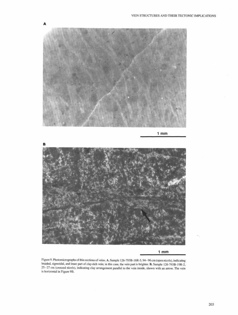
From these SEM studies and photomicrographs, it is known thatthe vein part is much richer in clay than the matrix, which includessome fragments. In these cases, clay minerals are sometimes arrangedparallel to the walls of the vein (Fig. 9B).
Thus, we conclude that the veins were preferentially formed in moreradiolarian-dominant claystone or mudstone, and the vein part was
occupied by clay minerals arranged parallel to the extension of thevein. These observations suggest that clay minerals were depositedeither by clay mineral injection or recrystallization within the veins.
Vein Shape and Arrangement
Veins were generally formed parallel to each other, and the mostprimitive style in the incipient stage is a fish style (Fig. 10). However,
200

VEIN STRUCTURES AND THEIR TECTONIC IMPLICATIONS
0.2 mm
Figure 7. A. SEM photograph of nonvein part illustrating radiolarian-dominant mudstone (Sample 126-793B-12R-1, 21-23 cm). B. Vein part illustrating parallel arrangement of clay minerals and spine(same sample as in Figure 7A).
in many cases the vein develop in an anastomosing manner. Theanastomosing angles are mostly 10° to 20° (Fig. 9A). We usually didnot see displacements along the vein of the incipient stage, suggestingthat the vein is just an extensional fracture, particularly in the centralpart. Sometimes, however, veins displace the bedding trace or pre-vious veins, indicating shear fractures. In the latter case, there are twotypes of shear fracture.
In one type, bifurcation occurs at both ends (the top and bottomof the vein), even in fish-style veins (Fig. 10; see fig. 3 in Ogawa andMiyata, 1985). The bifurcation may represent conjugate shear frac-tures. In the other case, the veins have two or more stages. Clear-cutrelations between the first and second stages are few, but it is alwayssuggested that the central bolder part is older than the thin parts, whichare seen as braiding from the central part that occurred in the second
201

Y. OGAWA, J. ASHI, K. FUJIOKA
0-01 mm
Figure 8. A, B. SEM photographs of vein part (Sample 126-787B-8R-1, 11-13 cm). The arrow inFigure 8 A indicates the wall of the vein enlarged in Figure 8B.
stage (Fig. 10; Knipe, 1986). In most cases, veins of the second stageare more vertical than in the first stage, which has rotated around thecentral part, opposing the previously mentioned vein obliqueness tothe bedding, unlike the examples of Knipe (1986) or Saito andNagahama(1989).
Sometimes, a bedding subparallel fault gouge was observed, asexplained by Kimura et al. (1989). The feature inside of the fault is
very similar to that of the vein structure, but the former never thinsout and is almost parallel to the bedding plane and is straighten Thefault gouge has a Cataclastic texture, as indicated in Ogawa and Miyata(1985), suggesting that arather strong breaking of the grains occurredby strain hardening. Sometimes veins cut the fault gouge and some-times vice versa, indicating that the vein formed both before and afterthe bedding plane sliding.
202
VEIN STRUCTURES AND THEIR TECTONIC IMPLICATIONS
1 mm
•
1 mm
Figure 9. Photomicrographs of thin sections of veins. A. Sample 126-793B-16R-5,94-96 cm (open nicols), indicatingbraided, sigmoidal, and inner part of clay-rich vein; in this case, the vein part is brighter. B. Sample 126-793B-19R-2,25-27 cm (crossed nicols), indicating clay arrangement parallel to the vein inside, shown with an arrow. The veinis horizontal in Figure 9B.
203

Y. OGAWA, J. ASHI, K. FUJIOKA
σ,
α
_α
Bedding trace
Incipient stage
Sigmoidal vein
Figure 10. The incipient stage of vein, indicating a fish style (left), and the developed stage,indicating a sigmoidal style (right). <^ and α are discussed in Figure 13.
ATTITUDE OF VEIN BY MAGNETICMEASUREMENT
Procedure
The cores are almost vertical, so that samples in the tube have anorientation within a horizontal X-Y plane; then the arrow is almostvertical in an X-Z plane (Fig. 2). However, in this case, we do notknow the real north direction in an X-Y plane. Therefore, we firstassumed that X = magnetic north; then we measured the strike anddip of the vein plane within this coordinate. Natural remanentmagnetization (NRM) was done with the Schonstedt spinner mag-netometer (SSM-1A) at the Ocean Research Institute, Universityof Tokyo. The NRM intensities of the samples range from 7.31 × I0"6
to 4.55 × 10""* emu/gr. The intensity was fairly stable after alternat-ing-field (AF) demagnetization. We used a Schonstedt two-axis tum-bler demagnetizer with a maximum AF up to 100 or 600 mT until thesample showed a constant direction of magnetic orientation. Anexample of the demagnetization path is shown in Figure 11.
Results
The results of the above experiments are given in Table 1, and theattitude of each vein (calculated using the constant direction demagneti-zation) is projected in Figure 12. The processes may contain systematicerrors that arose during the various stages. The greatest error was fromthe measurement of the vein plane at the beginning relative to theX-Yplane, because most of the veins were anastomosing in two dominantdirections. In all cases, we measured the general direction of the veins,so this may account for an error of about 5° in the strike and dip. Inaddition, too few samples were measured. We usually need at least threesamples from each location; however, because of the sampling policy, wewere limited to one sample per core.
If we look at Figure 12, we can see that the strikes of the vein varyfrom 275° to 360° (i.e., 315° ± 40°), and the dips are very steep(more than 70°). Furthermore, most are vertical at Site 793. Thestrong NRM measurements were taken at either the point of sedimen-tation or veining. The sedimentary magnetism was possibly convertedat the time of the clay mineral recrystallization, or it remained still
E, up
N rπ—r~r
• Horizontalo Vertical
W, down
Figure 11. Example of change of orthogonal components of magnetization withAF demagnetization, Sample 126-793B-19R-2, 25-27 cm; 0-40 mT; scale =10 mA/ra per division.
Table 1. Remanence properties of discrete samples, Holes 787B and 793B.
Core, section,interval (cm)
126-787B-8R-1, 11-139R-1, 11-1310R-1,11-1311R-1, 21-23
126-793B-12R-1, 21-2316R-5,94-9617R-2,73-7518R-3,82-841 9 R Λ 25-27
Optimum AF(mT)
40.010.020.0
7.5
30.010.07.5
15.040.0
Declination(degrees)
110.7106.9101.8-89.4
98.592.2
243.9123.1
11.6
Inclination(degrees)
43.355.619.0
-65.0
-35.958.6
-28.1
-60.6
70(mA/m)
316.80482.40115.20205.20
265.3233.12
145.2612.83
127.98
/AF(mA/m)
29.7567.9718.7566.18
31.554.75
23.069.60
11.97
204

VEIN STRUCTURES AND THEIR TECTONIC IMPLICATIONS
Hole 787B
787B-9R N 787B-8R
Hole 793B
793B-19R
793B-18R793B-17R
793B-16R
793B-12R
Figure 12. Calculated and projected direction of the vein plane, for the strongest NRM stage, using theWulf's net, lower hemisphere. For sample numbers, refer to Figure 3.
strong until this time. This needs to be checked in the future. However,our tentative results imply that the veins formed with a dominantlynorthwest-southeast strike and subvertical dips.
DISCUSSION
Tectonic Significance of Vein Structure Formation
These kinds of vein structure were first described on land asfracture cleavages at the time of dewatering, called "beardlike veinletstructure" by Ogawa (1980) in the Miura and Boso peninsulas to thenorthern extension of the Izu-Bonin forearc in central Honshu. Henoticed that the vein structures were associated with normal faultingunder horizontally extensional conditions and acted as a dewateringpath. From the sea bottom, similar structures were found from theJapan Trench landward slope by Arthur et al. (1980) and later Leggettet al. (1987); they concluded that this was a dewatering phenomena.However, most of the veins are constrained within a zone so that theyform an array within a single bed. Each vein thins out to both sides,suggesting that it was not formed by dehydration. A dewatering veinthat serves as a pipe or that dewaters along a fault plane differs fromthese vein structures. We think that the vein structures in these sampleswere not effectively dewatering.
Vein structures from the landward-slope sediments of the MiddleAmerica Trench have been extensively described by Cowan (1982)and Ogawa and Miyata (1985). They concluded that these veinstructures were formed as fracture cleavages under horizontal exten-sion and were later modified into sigmoidal shapes by downslopesliding. On the other hand, Helm and Vollbrecht (1985) hypothesizedthat these same sites were formed by antithetic Riedel shearing.
Vein structures seen within the Oceanic Formation of BarbadosIsland occur in the forearc basin. Also, they were found in both theseaward and landward slopes of the accretionary margin in theBarbados Ridge accretionary prism in ODP Leg 110 (Moore, Mascle,et al., 1989). In the latter case, the veins were thought to be formedby horizontal shearing around the incipient decollement zone beforebeing incorporated into the accretionary prism (Behrmann et al.,1988; Brown and Behrmann, 1990). However, Ogawa's preliminaryhypothesis during Leg 110 was that the veins were formed by verticalcompression around the normal fault in the downgoing slab in anoceanic plate realm.
Kimura et al. (1989) discovered a vein structure from the pistoncore taken from the seaward slope of the Yap Trench and concludedthat it was formed by Riedel shearing in conjunction with subhori-zontal shearing planes. They thought that the vein structures neededslope instability to form a sliding plane and that the shearing associ-ated with such a sliding regime would cause the vein structures to beRiedel or anti-Riedel shear planes.
Beside these forearc settings, the occurrence of vein structures inthe backarc settings have also been reported significantly. Iwamatsu(1979) included a picture of a vein structure in the Pliocene NishiyamaMudstone Formation on the Japan Sea side, central Honshu, thatcorresponds to a backarc setting. Some siliceous deposits from theMiocene Onnagawa Formation in the backarc area of the northernHonshu also yielded vein structures (T.Tsuji, pers. comm., 1990).
Thus, several tectonic settings exist for the formation of veinstructures in the world. Generally, however, it can be stated that veinstructures were formed on trench-landward-slope settings, with someexceptions that formed in the lower position of the incipient subduc-tion zone decollement, as has been thought in the Barbados case andthe backarc setting in central and northern Honshu. All of thesesettings favor a horizontal stretching of the strain field rather than ashortening of it.
Similar ideas about shear stress conditions on slopes have beensuggested by such authors as Ritger (1985), Knipe (1986), ShipboardScientific Party (1990), Saito and Nagahama (1989), and Brown andBehrmann (1990). Most of these authors have suggested that thesubhorizontal shear plane may rotate around the original tension gashthat developed from an extensional fracture or from a Riedel shear toa sigmoidal pattern. Sometimes these authors have claimed that thesubhorizontal shear planes have penetrated the central vein structureparts as a result of strong shearing.
Formation of Vein Structures
Clay mineral formation within the veins is thought to occur asfollows: The veins may originally form as either extension or shearfractures. With regard to extension fractures, they can be formed byhydraulic fracturing under high pore pressures. Even if differentialstresses are not large, fluid pressures can be high enough to cause theMohr's circle to contact the Mohr envelope surface in the diagram(Fig. 13) and extensional fractures can occur. If the differentialstresses are small enough, σ< 4 To (To=extensional strength) (Suppe,1985). On the other hand, a conjugate shear fracture would be formedif σ< -4ΛT^~ TO, as indicated by Suppe (1985). A hydraulic fracturecan occur in nature when high pore pressure results from eithertectonic pumping (Price, 1978; Moore, 1989) or compaction, whichmay prevent water escaping through low or no permeability. The lattercase may preferentially occur when a lot of clayey sediments are present.When high pore pressure conditions continue during fracturing withinthe vein, the veining formation may be the last structure to develop.
When fluid pressures are equal to lithostatic pressures, parallelbedding slides may be caused even by low oblique tangential stresseson the bedding plane because that part is weak enough. In this case,the vein could be still subvertical to the bedding plane. Thus, these
205

Y. OGAWA, J. ASHI, K. FUJIOKA
Mohr envelope
σ
Figure 13. Simple representation of vein formation at the time of pore fluidincreasing to produce hydraulic fracturing, and slip along a plane, whosenormal is at an angle α to the σ, direction. Diagonal line is the failure line forcollapsed sediment. See Figure 10.
two planes—the subvertical vein and the bedding parallel slip—canbe explained by the same stress field, as discussed by Mount andSuppe (1987) and Byrne and Fisher (1990). This case is illustrated inFigure 13.
When the stress drop occurs at the time of fracturing, the surround-ing pore fluids, which might be rich in suspended clay contents,invade the vein, and then clay minerals such as montmorillonite aredeposited. These clay minerals are sometimes arranged parallel to thevein and sometimes at random. In the former case, this is because flowalong the vein may have brought the clay grains.
At Site 784 (Leg 125), vein structures are present even in thePliocene section. The cored samples are very soft and are called "clay"instead of claystone. This means that the veining might have occurredwhen the sediment became just barely compacted and were onlyslightly strengthened. The clay is coherent because of its clay mineralcoherency; more radiolarian or vitric ash content could possibly bemore rapidly cemented by the recrystallization of those materials. Thefracturing needs a certain strength, either extensional or shear, beforeit can flow. This is one of the reasons that a definite Lithology andhorizon contain the vein structures.
It is known that veins are sometimes formed vertical to the beddingplane and have symmetrical braided tails on each of the edges. Usuallyno displacement occurs in the central part, although some displace-ment in a normal fault sense is seen in the braided parts. This suggeststhat veins originated as extension fractures from the central part andthen became shear fractures at the edges, both associated with thevertical plane. On the other hand, sometimes veins are either slightlyor considerably inclined to the bedding plane, which suggests thatthey are the result of subvertical or inclined fractures. Sometimes aslight dislocation is observed, suggesting that shear motion occurredalong the vein plane. In this case, the vein originated from a normalfault (or possibly an extensional or shear joint at first) and wasdislocated later in association with anastomosation and rotation. Thesigmoidal vein shapes indicate that rotation is necessary during theirdevelopment. The shearing sense for the bedding slip can coexist withthe development of veins as a tension gash.
Thus, although there are two types of vein structures, it is notablethat veins can occur as either tension gashes or shear fractures. In bothcases, they usually must be vertical or subvertical to the beddingplane. The differential stress must be very small under fairly shallowdepths. Several stages of vein formation are explained by the rotationof veins caused by shearing. In most cases, the sense of shear isdownslope for normal faulting as it is for the vein array, as indicated
in many places (Ogawa and Miyata, 1985; Shipboard Scientific Party,1990). This strongly supports the fact that a horizontal stretchingstress field occurs in the near-surface of most forearc regions.
As described in the thin section chapter, the materials within theveins are mostly clay minerals. This indicates that they were depositedin the fluid filling the vein. As discussed in Ogawa and Miyata (1985)and suggested in Shipboard Scientific Party (1990) and Knipe (1986),the stress drop (reduced stress) at the time of fracture formation mightevacuate the surrounding water, which is rich in clay content, toprecipitate the clay mineral. Such a hypothesis for vein formation ismost preferable.
Tectonic Implication of Vein Structures
The on-land example in the Miura-Boso peninsulas was takenfrom the Miocene to Pliocene accretionary prism in central Honshu(Ogawa et al., 1985, 1989). In this case, the accreted sediments werethought to be deposited originally on the trench landward slope of theIzu-Bonin island arc and then incorporated landward by the subdue-tion and accretion of the Philippine Sea Plate.
The two sites for the vein structures covered in this study are locatedin the outer part of the forearc basin of the Izu-Bonin island arc. This basinoriginated from the "failed rift" that opened along the volcanic frontduring the early Oligocene for a short period (Taylor, Fujioka, et al., 1990,pp. 315-403). Sediments were deposited first as volcaniclastic rocksduring the Oligocene; scarce volcanic materials were then depositedduring the Miocene. North-trending normal faulting occurred within theforearc basin to stretch the sediments; it is not yet known exactly whenthe stretching occurred in the forearc basin.
Even if the veins were formed as extensional fractures subverticalto the bedding plane or as shear tension gashes under shear stress, ourresults (i.e., that most vein planes trend northwest) substantiate ourinterpretation that the veins were formed under the northeast-stretch-ing stress field. The veins may have formed at an early stage aftersedimentation, possibly during late Oligocene to Miocene time. It issaid that the Izu-Bonin island arc was once connected to the presentKyushu-Palau Ridge to form a proto Izu-Bonin-Mariana island arcbefore the opening of the Shikoku-Parece Vela basin (before 30 Ma;i.e., late Oligocene). We do not know the exact stage of the veinformation, but it may have occurred when the Izu-Bonin Arc was stilltrending northwest, or during the change from a northwest to a northtrend between 30 and 16 or 12 Ma (Seno and Maruyama, 1984;Chamot-Rooke et al., 1987; Jolivet et al., 1989). This interpretationmust still be checked by various points of view, but if correct, thenthe veins formed during extension are perpendicular to the arc.
ACKNOWLEDGMENTS
We are grateful to the onboard staff who took the vein samples.Critical reviews and suggestions by Brian Taylor, Darrel S. Cowan,Gaku Kimura, and an anonymous reviewer are greatly appreciated. Apart of the study was supported by the funds from the CooperativeProgram (No. 90011) provided by the Ocean Research Institute,University of Tokyo, to Y. Ogawa.
REFERENCES
Arthur, M. A., Carson, B., and von Huene, R., 1980. Initial tectonic deforma-tion of hemipelagic sediment at the leading edge of the Japan convergentmargin. In Langseth, M., Okada, H., et al., Init. Repts. DSDP, 56, 57, Pt. 1:Washington (U.S. Govt. Printing Office), 569-613.
Behrmann, J., Brown, K., Moore, J. C, Mascle, A., Taylor, E., Alvarez, F.,Andreieff, P., Barnes, R., Beck, C, Blanc, G., Clark, M., Dolan, J. F.,Fisher, A., Gieskes, J., Hounslow, M. W., McLellan, P., Moran, K., Ogawa, Y.,Sakai, T., Schoonmaker, J., Vrolijk, P., Wilkens, R. H., Williams, C. F.,1988. Evolution of structures and fabrics in the Barbados AccretionaryPrism: insights from Leg 110 of the Ocean Drilling Program. J. Struct.Geol., 10:577-591.
206

VEIN STRUCTURES AND THEIR TECTONIC IMPLICATIONS
Brown, K. ML, and Behrmann, J., 1990. Genesis and evolution of small-scalestructures in the toe of the Barbados Ridge accretionary wedge. In Moore,J. C, Mascle, A., et al., Proc. ODP, Sci. Results, 110: College Station, TX(Ocean Drilling Program), 229-244.
Byrne, T., and Fisher, D., 1990. Evidence for a weak and overpressureddecollement beneath sediment-dominated accretionary prisms. J. Geo-phys. Res., 95:9081-9097.
Chamot-Rooke, N., Renard, V, and Le Pichon, X., 1987. Magnetic anomalies inthe Shikoku basin: anew interpretation. Earth Planet. Sci. Lett., 83:214-228.
Cowan, D. S., 1982. Origin of "Vein Structure" in slope sediments on the innerslope of the Middle America Trench off Guatemala. In Aubouin, J., vonHuene, R., et al, Init. Repts. DSDP, 67: Washington (U.S. Govt. PrintingOffice), 645-650.
Helm, R., and Vollbrecht, A., 1985. Brittle-ductile shear zones in slopesediments off Guatemala, Site 568 and 569, Deep Sea Drilling ProjectLeg 84. In von Huene, R., Aubouin, J., et al., Init. Repts. DSDP, 84: Washington(U.S. Govt. Printing Office), 625-632.
Iwamatsu, A., 1979. Cleavages in rock. In Uemura, T. (Ed.), Geologic Struc-tures and Their Developments: Tokyo (Iwanami Book Co.), 161-185.
Jolivet, L., Huchon, P., and Rangin, C, 1989. Tectonic setting of WesternPacific marginal basins. Tectonophysics, 160:23-47.
Kimura, G., Koga, K., and Fujioka, F., 1989. Deformed soft sediments at thejunction between the Mariana and Yap trenches. J. Struct. Geol, 11:463-472.
Knipe, R. J., 1986. Microstructural evolution of vein arrays preserved in DeepSea Drilling Project cores from the Japan Trench, Leg 57. In Moore, J. C.(Ed.), Structural Fabrics Preserved in Deep Sea Drilling Project Coresfrom Forearcs. Mem. Geol. Soc. Am., 166:75-87.
Leggett, J. K., Lundberg, N., Bray, C. J., Cadet, J. P., Karig, D. E., Knipe, R. J.,and von Huene, R., 1987. Extensional tectonics in the Honshu forearc,Japan: integrated results of Deep Sea Drilling Project Legs 57, 87, andreprocessed seismic reflection profiles. Spec. Publ., Geol. Soc. London,28:593-609.
Lundberg, N., and Moore, J. C, 1986. Macroscopic structural features in DeepSea Drilling Project cores from forearc regions. In Moore, J. C. (Ed.),Structural Fabrics Preserved in Deep Sea Drilling Project Cores fromForearcs. Mem. Geol. Soc. Am., 166:13-44.
Moore, J. C, 1989. Tectonics and hydrogeology of accretionary prisms: roleof the decollement zone. J. Struct. Geol., 11:95-106.
Moore, J. C, Mascle, A., Taylor, E., Alvarez, F, Andreieff, P., Barnes, R., Beck, C,Behrmann, J., Blanc, G., Brown, K. M., Clark, M., Dolan, J. F, Fisher, A.,Gieskes, J. M., Hounslow, M., McLellan, P., Moran, K, Ogawa, Y, Sakai, T.,Schoonmaker, J., Vrolijk, P., Wilkens, R. H., and Williams, C, 1988.Tectonics and hydrogeology of the northern Barbados Ridge: results fromOcean Drilling Program Leg 110. Geol. Soc. Am. Bull., 100:1578-1593.
Mount, V. S., and Suppe, J., 1987. State of stress near the San Andreas fault:implications for wrench tectonics. Geology, 15:1143-1146.
Ogawa, Y, 1980. Beard-like veinlet structure as fracture cleavage in theNeogene siltstone in the Miura and Boso peninsulas, central Japan. 5c/.Rep. Dept. Geol., Kyushu Univ., 13:321-327.
Ogawa, Y, Horiuchi, K., Taniguchi, H., and Naka, J., 1985. Collision of theIzu Arc with Honshu and the effects of oblique subduction in the Miura-Boso peninsulas. Tectonophysics, 119:349-379.
Ogawa, Y, and Miyata, Y, 1985. Vein structure and its deformation history inthe sedimentary rocks of the Middle America Trench slope off Guatemala,Deep Sea Drilling Project Leg 84. In von Huene, R., Aubouin, J., et al.,Init. Repts. DSDP, 84: Washington (U.S. Govt. Printing Office), 811-529.
Ogawa, Y, Seno, T, Akiyoshi, H., Tokuyama, H., Fujioka, K., and Taniguchi, H.,1989. Structure and development of the Sagami trough and the Boso triplejunction. Tectonophysics, 160:135-150.
Price, N. J., 1978. Permeability, hydraulic fracture and elasticity. In Fyfe, W. S.,Price, N. J., and Thompson, A. B. (Eds.), Fluids in the Earth's Crust:Amsterdam (Elsevier), 253-273.
Ritger, S. D., 1985. Origin of vein structures in the slope deposits of modernaccretionary prisms. Geology, 33:437-439.
Saito, S., and Nagahama, H., 1989. Geometry and geological significance of"vein structure" in soft sediment. /. Tecton. Res. Group Jpn., 34:27-36.
Seno, T, and Maruyama, S., 1984. Paleogeographic reconstruction and originof the Philippine Sea. Tectonophysics, 102:53-84.
Shipboard Scientific Party, 1990. Site 784. In Fryer, P., Pearce, J. A., et al.,Proc. ODP, Init. Repts., 125: College Station, TX (Ocean Drilling Pro-gram),. 273-305.
Suppe, J., 1985. Principles of Structural Geology. Englewood Cliffs, NJ(Prentice-Hall).
Taylor, B., Fujioka, K., et al., 1990. Proc. ODP, Init. Repts., 126: CollegeStation, TX (Ocean Drilling Program).
Taylor, B., Moore, G., Klaus, A., Systrom, M., Cooper, P., and MacKay, M.,1990. Multichannel seismic survey of the central Izu-Bonin Arc. In Taylor, B.,Fujioka, K., et al., Proc. ODP, Init. Repts., 126: College Station, TX (OceanDrilling Program), 51-60.
Date of initial receipt: 2 November 1990Date of acceptance: 29 May 1991Ms 126B-128
207