13 SEER CONDENSING UNIT INSTALLER'S ... 13 SEER CONDENSING UNIT INSTALLER'S INFORMATION MANUAL...
9
816010 13 SEER CONDENSING UNIT INSTALLER'S INFORMATION MANUAL ATTENTION, INSTALLER! After installing the system, show the user how to turn off electricity to the unit. Point out control and switch locations for turning off electricity. Make sure the user understands the importance of following all safety precautions, including what could happen if they don't. Keep the following documents in a safe, accessible location. Tell the user where these documents are located: • Installer's Information Manual • Parts List • Warranty Information While these instructions have been written as accurately and thoroughly as possible, they may not cover every system variation or contingency. Questions of interpretation may arise. For more information, solutions to particular problems or clarification, contact your local distributor or the manufacturer. ATTENTION, USER! Your equipment installer should give you the important documents listed above. You should become familiar with these instructions, as it will be helpful in avoiding any needless service costs or operational problems. Keep these instructions as long as you keep your equipment for future reference. If any of the documents are missing or illegible, contact your installer or equipment manufacturer for replacement. Throughout this manual, when we use the word "you" we refer to the qualified service technician who is responsible for application, installation and service of your equipment. While these instructions are addressed primarily to the installer, useful maintenance information is included. Have your installer acquaint you with the operating characteristics of the product and periodic maintenance requirements. WARNING: Individuals who install this equipment, must have the training and experience necessary to install comfort air conditioning appliances. Before performing any work on this equipment, the power supply must be turned off at the household service box. Improper installation could void the warranty; create a hazard, resulting in the possibility of damage, injury or death.
Transcript of 13 SEER CONDENSING UNIT INSTALLER'S ... 13 SEER CONDENSING UNIT INSTALLER'S INFORMATION MANUAL...

816010
13 SEER CONDENSING UNIT INSTALLER'S INFORMATION MANUAL
ATTENTION, INSTALLER! After installing the system, show the user how to turn off electricity to the unit. Point out control and switch locations for turning off electricity. Make sure the user understands the importance of following all safety precautions, including what could happen if they don't.
Keep the following documents in a safe, accessible location. Tell the user where these documents are located: • Installer's Information Manual • Parts List • Warranty Information
While these instructions have been written as accurately and thoroughly as possible, they may not cover every system variation or contingency. Questions of interpretation may arise. For more information, solutions to particular problems or clarification, contact your local distributor or the manufacturer.
ATTENTION, USER! Your equipment installer should give you the important documents listed above. You should become familiar with these instructions, as it will be helpful in avoiding any needless service costs or operational problems. Keep these instructions as long as you keep your equipment for future reference. If any of the documents are missing or illegible, contact your installer or equipment manufacturer for replacement.
Throughout this manual, when we use the word "you" we refer to the qualified service technician who is responsible for application, installation and service of your equipment.
While these instructions are addressed primarily to the installer, useful maintenance information is included. Have your installer acquaint you with the operating characteristics of the product and periodic maintenance requirements.
WARNING: Individuals who install this equipment, must have the training and experience necessary to install comfort air conditioning appliances. Before performing any work on this equipment, the power supply must be turned off at the household service box. Improper installation could void the warranty; create a hazard, resulting in the possibility of damage, injury or death.
Page 2 Installer’s Information Manual
TABLE OF CONTENTS SECTION 1. GENERAL INFORMATION ................................................................................ 2 SECTION 2. MEETING CODES ............................................................................................. 3 SECTION 3. DETERMINING CONDENSER LOCATION ....................................................... 3 SECTION 4. REFRIGERANT PIPING CONNECTIONS ......................................................... 4 SECTION 5. ELECTRICAL CONNECTION ............................................................................ 5 SECTION 6. REFRIGERANT CHARGE.................................................................................. 6 SECTION 7. CHECKOUT PROCEDURE................................................................................ 7 SECTION 8. MAINTENANCE ................................................................................................. 7 SECTION 9. TROUBLE-SHOOTING CHART......................................................................... 9
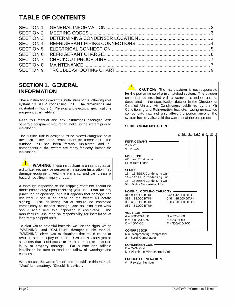
SECTION 1. GENERAL INFORMATION These instructions cover the installation of the following split system 13 SEER condensing unit. The dimensions are illustrated in Figure 1. Physical and electrical specifications are provided in Table 2.
Read this manual and any instructions packaged with separate equipment required to make up the system prior to installation.
The outside unit is designed to be placed alongside or at the back of the home, remote from the indoor coil. The outdoor unit has been factory run-tested and all components of the system are ready for easy, immediate installation.
WARNING: These instructions are intended as an aid to licensed service personnel. Improper installation may damage equipment, void the warranty, and can create a hazard, resulting in injury or death.
A thorough inspection of the shipping container should be made immediately upon receiving your unit. Look for any punctures or openings, and if it appears that damage has occurred, it should be noted on the freight bill before signing. The delivering carrier should be contacted immediately to inspect damage, and no installation work should begin until this inspection is completed. The manufacturer assumes no responsibility for installation of incorrectly shipped units.
To alert you to potential hazards, we use the signal words "WARNING" and "CAUTION" throughout this manual. "WARNING" alerts you to situations that could cause or result in serious injury or death. "CAUTION" alerts you to situations that could cause or result in minor or moderate injury or property damage. For a safe and reliable installation be sure to read and follow all warnings and cautions.
We also use the words "must" and "should" in this manual. "Must" is mandatory. "Should" is advisory.
CAUTION: The manufacturer is not responsible for the performance of a mismatched system. The outdoor unit must be installed with a compatible indoor unit as designated in the specification data or in the Directory of Certified Unitary Air Conditioners published by the Air Conditioning and Refrigeration Institute. Using unmatched components may not only affect the performance of the system but may also void the warranty of the equipment
SERIES NOMENCLATURE
2 AC 13 042 A S M 1
REFRIGERANT 2 = R22 4 = R410a UNIT TYPE AC = Air Conditioner HP = Heat Pump SERIES 13 = 13 SEER Condensing Unit 14 = 14 SEER Condensing Unit 16 = 16 SEER Condensing Unit 5# = 50 Hz Condensing Unit NOMINAL COOLING CAPACITY 018 = 18,000 BTUH 042 = 42,000 BTUH 024 = 24,000 BTUH 048 = 48,000 BTUH 030 = 30,000 BTUH 060 = 60,000 BTUH 036 = 36,000 BTUH VOLTAGE A = 208/230-1-60 D = 575-3-60 B = 208/230-3-60 E = 230-1-50 C = 460-3-60 F = 380/415-3-50 COMPRESSOR R = Reciprocating Compressor S = Scroll Compressor CONDENSER COIL C = Cu/Al Coil M = Aluminum Microchannel Coil PRODUCT GENERATION # = Revision Number


Page 4 Installer’s Information Manual
A minimum clearance of 18 inches is required for service at the control panel access. A 12 inch clearance is required for the air inlet to the outdoor coil around the perimeter of the unit. The air discharge of the unit requires a 60 inch clearance between the top of the unit and any obstruction. See Figure 2.
The length of the refrigerant tubing, between the outdoor unit and indoor coil, should be as short as possible to avoid capacity and efficiency loss. Excessive spacing of the outdoor unit from the home can lead to the refrigerant lines being restricted by trampling or by being punctured by lawn mowers. Locate the outdoor unit away from bedroom windows or other rooms where sound might not be desirable.
Provide sufficient clearance from shrubs to allow adequate air to pass across the outdoor coil without leaves or branches being pulled into the coil.
Consideration should be given to the distance and routing of electrical service that would have to be run to connect the outdoor unit.
The outdoor unit may be installed at ground level on a solid base that will not shift or settle, causing strain on the refrigerant lines and possible leaks. Isolate the base from the structure to avoid noise or vibration transmission. When installing units on a roof, a structure should be used to minimize the transmission of sound or vibration into the conditioned space. Thought should be given to water drainage away from the outdoor unit. Drain holes in the base pan must be kept clear.
12" Clearancearound unit
18" Clearancefor Service Area
60" Clearance Above Unit
To Indoor Coil
NEC Class 1 Wiring
Power Supply
NEC Class 2Wiring
ThermostatTo Indoor Air Handler or Furnace
Figure 2. Typical Location and Clearances
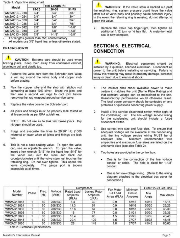
SECTION 4. REFRIGERANT PIPING CONNECTIONS Undersized line sets will increase the refrigerant pressure drop between the indoor evaporator and outdoor unit, resulting in a decrease in system capacity. Over sizing the line sets may result in excessive refrigerant charge, thereby making the system more susceptible to liquid migration. Slope horizontal vapor lines at least 1” every 20 feet toward the outdoor unit to facilitate proper oil return.
Use only refrigerant grade (dehydrated and sealed) copper tubing of the size indicated in Table 1 to interconnect the condensing unit with the indoor evaporator. Take extreme
care to keep the refrigerant tubing clean and dry prior to and during installation. All outdoor unit and evaporator coil connections are copper to copper and should be brazed with a phosphorous-copper alloy material such as Silfos-5 or equivalent instead of soft solder. The outdoor units have re-usable service valves on both the liquid and vapor connections. Precautions should be taken to prevent heat damage to the valve by wrapping a wet rag around it when brazing.
Do not remove plugs from ends of tubing until connection is ready to be made. Suction line insulation is necessary to prevent condensation from forming on and dropping from suction line. Apply suction line insulation by sliding it on the sealed tubing before cutting and making connections. See Table 1 for correct vapor line size.

Page 6 Installer’s Information Manual
5. Be sure to ground the condensing unit by securing the ground wire to the grounding lug inside the control box.
6. Be sure to follow National Electrical Code and all local codes
NOTE: Use copper conductors only.
CAUTION: Casing or cabinet must be permanently grounded in accordance with National Electric Code or other applicable local codes.
SECTION 6. REFRIGERANT CHARGE Condensing units are supplied with a refrigerant charge (R-22) sufficient for typical matching evaporator and approximately 25 feet of interconnecting tubing. Condensing unit liquid and suction valves are closed to contain the charge within the unit.
MEASUREMENT
If a calibrated charging cylinder or accurate weighing device is available, add refrigerant accordingly.
CAUTION: Refrigerant charging should only be carried out by a qualified air conditioning contractor.
FIELD CHARGING
Depending on the type of restricting device that is installed on the system (TXV, piston, capillary tubes, etc.), the subcooling or superheat charging method can be used for field charging or checking the existing refrigerant charge in a system. Because each installation is different in terms of indoor air flow, refrigerant line length, and duct variations, etc., the factory charge may not be correct for every application. To assure the best performance from the air conditioner, the refrigerant charge should be checked and adjusted when needed on each installation.
CAUTION: Compressor damage will occur if system is improperly charged. On new system installations, charge the system per refrigerant charge information label and follow guidelines in these instructions.
WARNING: Refrigerant is under pressure. Guard against refrigerant spraying into the face or on skin. Always wear protective equipment, i.e. safety glasses or goggles and gloves when working with refrigerant.
SUBCOOLING CHARGING METHOD
The subcooling charging method is to be used on units which have Thermostatic Expansion Valve (TXV) as the expansion device. For proper subcooling readings, a standard high side gauge is required for pressure readings.
1. Measure the outdoor air temperature. (T1)
2. Measure the liquid line pressure at the outdoor unit and determine condenser refrigerant temperature by the scale on the high side pressure gauge. (T2)
3. Measure the liquid line temperature on the liquid line at the outdoor unit. (T3)
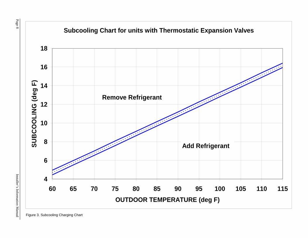
4. Subtract T3 from T2. (T2 – T3) This is the subcooling value. Compare this value and the outdoor temperature (T1), to the chart on page 8 (Figure 3). If the value is below the line, add refrigerant. If the value is above the line, remove refrigerant charge.
NOTE: When removing refrigerant, always use standard reclaim procedures.
NOTE: On cooler days (65degF or lower), attempts to operate the air conditioner and take gauged pressure readings may be unsuccessful, as unusually low pressures will be observed on the suction line. This type of operation may give the impression of an undercharged unit. Such is NOT necessarily the case. The low-pressure reading may exist because of the large condenser surface area and the cold ambient air removing so much heat from the refrigerant. Sub-cooling occurs and results in very low pressures. Adding refrigerant in cold weather will result in an overcharged unit, which may then trip out on high pressure limit during warm or hot weather. Line pressures should not be taken for test purposes when the outdoor temperature is below 70degF since a false reading may occur. Do not attempt to operate the air conditioner on a day of 45degF or cooler.
Installer’s Information Manual Page 7
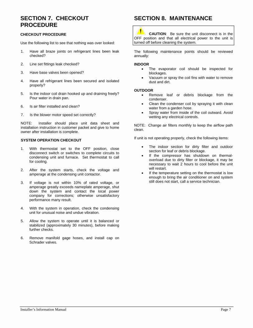
SECTION 7. CHECKOUT PROCEDURE CHECKOUT PROCEDURE
Use the following list to see that nothing was over looked:
1. Have all braze joints on refrigerant lines been leak checked?
2. Line set fittings leak checked?
3. Have base valves been opened?
4. Have all refrigerant lines been secured and isolated properly?
5. Is the indoor coil drain hooked up and draining freely? Pour water in drain pan.
6. Is air filter installed and clean?
7. Is the blower motor speed set correctly?
NOTE: Installer should place unit data sheet and installation instruction in customer packet and give to home owner after installation is complete.
SYSTEM OPERATION CHECKOUT
1. With thermostat set to the OFF position, close disconnect switch or switches to complete circuits to condensing unit and furnace. Set thermostat to call for cooling.
2. After the system starts, check the voltage and amperage at the condensing unit contactor.
3. If voltage is not within 10% of rated voltage, or amperage greatly exceeds nameplate amperage, shut down the system and contact the local power company for corrections; otherwise unsatisfactory performance many result.
4. With the system in operation, check the condensing unit for unusual noise and undue vibration.
5. Allow the system to operate until it is balanced or stabilized (approximately 30 minutes), before making further checks.
6. Remove manifold gage hoses, and install cap on Schrader valves.
SECTION 8. MAINTENANCE
CAUTION: Be sure the unit disconnect is in the OFF position and that all electrical power to the unit is turned off before cleaning the system.
The following maintenance points should be reviewed annually:
INDOOR • The evaporator coil should be inspected for
blockages. • Vacuum or spray the coil fins with water to remove
dust and dirt.
OUTDOOR • Remove leaf or debris blockage from the
condenser. • Clean the condenser coil by spraying it with clean
water from a garden hose. • Spray water from inside of the coil outward. Avoid
wetting any electrical controls.
NOTE: Change air filters monthly to keep the airflow path clean.
If unit is not operating properly, check the following items:
• The indoor section for dirty filter and outdoor section for leaf or debris blockage.
• If the compressor has shutdown on thermal-overload due to dirty filter or blockage, it may be necessary to wait 2 hours to cool before the unit will restart.
• If the temperature setting on the thermostat is low enough to bring the air conditioner on and system still does not start, call a service technician.
Page 8
Installer’s Information M
anual
Subcooling Chart for units with Thermostatic Expansion Valves
4
6
8
10
12
14
16
18
60 65 70 75 80 85 90 95 100 105 110 115
OUTDOOR TEMPERATURE (deg F)
SU
BC
OO
LIN
G (d
eg F
)
Remove Refrigerant
Add Refrigerant
Figure 3. Subcooling Charging Chart
Installer’s Information Manual Page 9
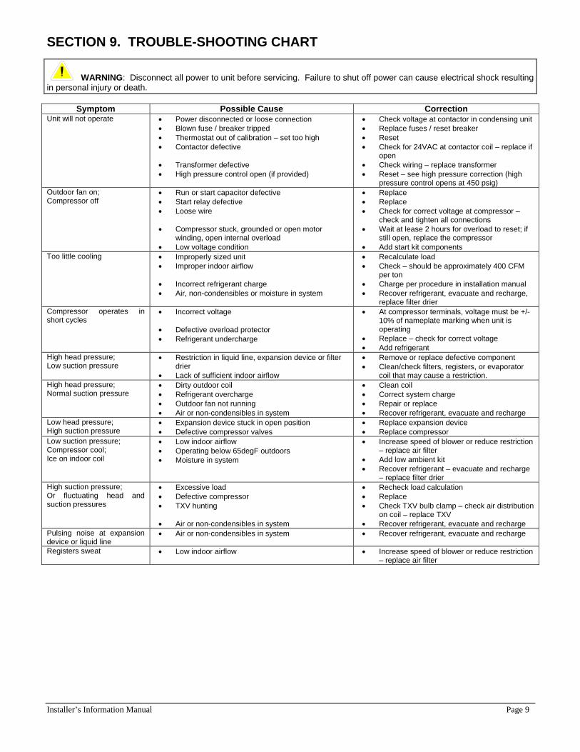
SECTION 9. TROUBLE-SHOOTING CHART
WARNING: Disconnect all power to unit before servicing. Failure to shut off power can cause electrical shock resulting in personal injury or death.
Symptom Possible Cause Correction Unit will not operate • Power disconnected or loose connection
• Blown fuse / breaker tripped • Thermostat out of calibration – set too high • Contactor defective • Transformer defective • High pressure control open (if provided)
• Check voltage at contactor in condensing unit • Replace fuses / reset breaker • Reset • Check for 24VAC at contactor coil – replace if
open • Check wiring – replace transformer • Reset – see high pressure correction (high
pressure control opens at 450 psig) Outdoor fan on; Compressor off
• Run or start capacitor defective • Start relay defective • Loose wire • Compressor stuck, grounded or open motor
winding, open internal overload • Low voltage condition
• Replace • Replace • Check for correct voltage at compressor –
check and tighten all connections • Wait at lease 2 hours for overload to reset; if
still open, replace the compressor • Add start kit components
Too little cooling • Improperly sized unit • Improper indoor airflow • Incorrect refrigerant charge • Air, non-condensibles or moisture in system
• Recalculate load • Check – should be approximately 400 CFM
per ton • Charge per procedure in installation manual • Recover refrigerant, evacuate and recharge,
replace filter drier Compressor operates in short cycles
• Incorrect voltage • Defective overload protector • Refrigerant undercharge
• At compressor terminals, voltage must be +/- 10% of nameplate marking when unit is operating
• Replace – check for correct voltage • Add refrigerant
High head pressure; Low suction pressure
• Restriction in liquid line, expansion device or filter drier
• Lack of sufficient indoor airflow
• Remove or replace defective component • Clean/check filters, registers, or evaporator
coil that may cause a restriction. High head pressure; Normal suction pressure
• Dirty outdoor coil • Refrigerant overcharge • Outdoor fan not running • Air or non-condensibles in system
• Clean coil • Correct system charge • Repair or replace • Recover refrigerant, evacuate and recharge
Low head pressure; High suction pressure
• Expansion device stuck in open position • Defective compressor valves
• Replace expansion device • Replace compressor
Low suction pressure; Compressor cool; Ice on indoor coil
• Low indoor airflow • Operating below 65degF outdoors • Moisture in system
• Increase speed of blower or reduce restriction – replace air filter
• Add low ambient kit • Recover refrigerant – evacuate and recharge
– replace filter drier High suction pressure; Or fluctuating head and suction pressures
• Excessive load • Defective compressor • TXV hunting • Air or non-condensibles in system
• Recheck load calculation • Replace • Check TXV bulb clamp – check air distribution
on coil – replace TXV • Recover refrigerant, evacuate and recharge
Pulsing noise at expansion device or liquid line
• Air or non-condensibles in system • Recover refrigerant, evacuate and recharge
Registers sweat • Low indoor airflow • Increase speed of blower or reduce restriction – replace air filter