128824400 Unisab III Operating en Logo
42
Compressor type: ____________________ Refrigerant: _____________ Shop no.: ________________________________________ Password: ________________________________________ Software version: ________________________________________ Operating manual - Unisab III Control Control system for refrigerating compressors Version 1.00 Operating manual - Unisab III 002672-en 2007.09 1/37
-
Upload
wilson-rodriguez-bustamante -
Category
Documents
-
view
688 -
download
70
Transcript of 128824400 Unisab III Operating en Logo

Compressor type: ____________________ Refrigerant: _____________
Shop no.: ________________________________________
Password: ________________________________________
Software version: ________________________________________
Operating manual - Unisab III Control
Control system for refrigerating compressors
Version 1.00
Operating manual - Unisab III002672-en 2007.09
1/37
Preface
This Unisab III Operating manual covers reciprocating as well as screw compressors, unlessotherwise stated. The manual offers a description of the Unisab III control system includingfunction, application and service.
This manual is produced by:
Johnson Controls Denmark ApSChristian X's Vej 2018270 Hoejbjerg, DenmarkPhone +45 87 36 70 00Fax +45 87 36 70 05CVR No 19 05 61 71
Copyright © 2007 Johnson Controls Denmark ApS
This manual must not be copied without the written permission of Johnson Controls DenmarkApS and the contents must not be imparted to any third parties nor be used for any unauthorisedpurposes. Contravention will be prosecuted.
Please read the manual carefully so that you fully understand the Unisab III control system andknow how to operate it correctly. Damage occurring as a result of incorrect operation is notcovered by Johnson Controls Denmark's guarantee.
Note the version number of this manual. The version number is printed on the preceding page.It is important that this number is identical to the Unisab III version number, which is shown inthe picture Service/Diagnosis/Software/Software version. Never use a manual with lower ver-sion number than Unisab III.
Warning!
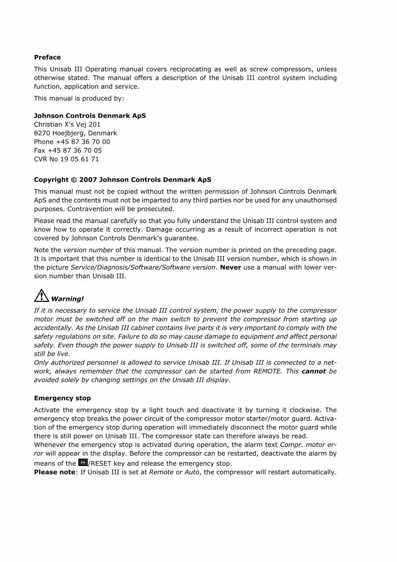
If it is necessary to service the Unisab III control system, the power supply to the compressormotor must be switched off on the main switch to prevent the compressor from starting upaccidentally. As the Unisab III cabinet contains live parts it is very important to comply with thesafety regulations on site. Failure to do so may cause damage to equipment and affect personalsafety. Even though the power supply to Unisab III is switched off, some of the terminals maystill be live.Only authorized personnel is allowed to service Unisab III. If Unisab III is connected to a net-work, always remember that the compressor can be started from REMOTE. This cannot beavoided solely by changing settings on the Unisab III display.
Emergency stop
Activate the emergency stop by a light touch and deactivate it by turning it clockwise. Theemergency stop breaks the power circuit of the compressor motor starter/motor guard. Activa-tion of the emergency stop during operation will immediately disconnect the motor guard whilethere is still power on Unisab III. The compressor state can therefore always be read.Whenever the emergency stop is activated during operation, the alarm text Compr. motor er-ror will appear in the display. Before the compressor can be restarted, deactivate the alarm by
means of the /RESET key and release the emergency stop.Please note: If Unisab III is set at Remote or Auto, the compressor will restart automatically.

Technical dataPower supply: Nominal VAC Tolerance Hz 85-250 47-63Consumption: 32 VA Ambient temperature: 0-55°C (during operation)Humidity: 10-90% relative humidity (not condensing)Tightness: IP 54
Operating manual - Unisab III002672-en 2007.09
3/37

Contents
1. Operating Unisab III control 5
1.1. Introduction 5
1.1.1. Start-up 5
1.1.2. Display 7
1.1.3. Front panel 7
1.1.4. Menu structure 9
1.1.5. Session 16
1.1.6. Changing set values 18
1.1.7. Favourites 20
1.1.8. Manual and auto operation 21
1.1.9. Shutdown and alarm acknowledgement 23
1.1.10. Factory setting 23
1.1.11. Set values 24
1.2. Pressure levels and temperatures 25
1.2.1. Measured and calculated pressure levels - screws 25
1.2.2. Measured and calculated temperatures - screws 26
1.2.3. Measured and calculated pressure levels - recips. 27
1.2.4. Measured and calculated temperatures - recips. 27
1.2.5. Measured/calculated pressure levels/temp. - HPO/HPC 28
1.2.6. Notes 29
1.2.7. Oil pressure calculations 31
1.3. Timers 32
1.3.1. Timer values - screw compressors 32
1.3.2. Timer values - reciprocating compressors 35
1.4. Spare parts 36
1.4.1. Spare parts for Unisab III 36
Operating manual - Unisab III002672-en 2007.09
4/37

1. Operating Unisab III control
1.1. Introduction
The purpose of the Unisab III control system is to monitor, protect, control and regulate recip-rocating and screw compressors. The control cabinet as well as the electrical components havebeen connected from factory. Thus, only a few connections are needed to link to the electricalinstallations on site.
Unisab III is programmed according to the type of compressor it is going to control. See sectionSetup (Engineering manual).
Unisab III offers different ways of controlling/regulating compressor capacity according to pres-sure levels or temperatures. Compressor capacity can be regulated both manually and auto-matically.
Furthermore, a number of limiting functions have been incorporated. In periods of overloadingthese limiting functions will intervene and limit compressor capacity until the situation has re-turned to normal. Consequently, the number of undesirable operational stops will be reducedas well as the need for supervision.
Compressors fitted with Unisab III Control can be linked via the built-in communication system,Multisab. In this way compressors can work in a common refrigerating system, thus optimizingthe operation of the entire compressor plant.
The communication system further allows Unisab III to be connected to a PLC or PC centralmonitoring, control and data logging system. Unisab III can be linked to and communicate withformer Sabroe control units such as Unisab II.
Unisab III is operated by means of a front panel as shown in Fig. 3. The front panel is well-arranged with only a few keys and a distinct display.
Unisab III does not lose its preset or changed values in the event of a temporary power failure.It contains a battery which is used by the built-in timer to ensure that time and date are alwayscorrect even if power has been disconnected. The hour counter and any stored alarm values willmaintain the correct time.
1.1.1. Start-upOn delivery all electrical components in the compressor are connected to Unisab III. On site itis only necessary to add the correct supply voltage from the local installations. The electric wiringmust be carried out according to the wiring diagrams for Unisab III at the end of this manual.
Note in particular that
• no outside voltage must be applied to the digital inputs of Unisab III.
• the supply voltage must be between 85 VAC and 250 VAC.
Before any voltage is applied to Unisab III, the emergency stop switch must be activa-ted. When voltage is applied to Unisab III, the default picture shown below will appear in thedisplay and Unisab III will be ready for operation.
Operating Unisab III control
Operating manual - Unisab III002672-en 2007.09
5/37

Fig. 1: Default picture
As Unisab III has been programmed with values for alarm limits, shutdown limits, set points,etc., the compressor can be started immediately.
However, some of the values must be adapted to the actual operating situation. It is also rec-ommended to read this manual carefully to acquire a thorough knowledge of how to operateUnisab III.
Unisab III is operated exclusively by means of the front panel keys. Reading of operating con-ditions as well as changing limiting values and set points is carried out via the display. Thedisplay contains a number of different pictures.
The control panel is usually closed and locked with two screws at the bottom of the front panel.When turning the screws, the front panel is loosened and can be lifted to an open position, yetstill fastened to the cabinet. See Fig. 2.
-
Fig. 2: Unisab III with front open
This way the front panel remains easy to operate and easy access to the cabinet interior isobtained. When Unisab III is open, it is still fully operational.
Operating Unisab III control
Operating manual - Unisab III002672-en 2007.09
6/37

1.1.2. Display
Top bar
Content area
Info barF-key area
Fig. 3: Unisab III front
DisplayThe display has a background illumination with screen saver function. It consists of a top barwith navigation information, a content area with 7-11 lines of information, an info bar withmode and status information and an F-key area with information about the active functionkeys. Pressure levels, temperatures, set points as well as alarm and shutdown limits can be readin the display. The contrast is factory set but may be adjusted, if required. See subsectionContrast (display) in the Engineering manual.
Compressor mode
Compressor status
Passwordsecurity
Information aboutactive timer
Compressor no. (if remote connected)
Actualcapacity
1
“Smiley” status:
OK
Alarm
Shutdown
Fig. 4: Info bar in Unisab III display
1.1.3. Front panelThe Unisab III front panel is divided into three sections:The control section - to control the compressor.The menu section - to select menu pictures and change values.The F-key section - to operate function keys.
Operating Unisab III control
Operating manual - Unisab III002672-en 2007.09
7/37
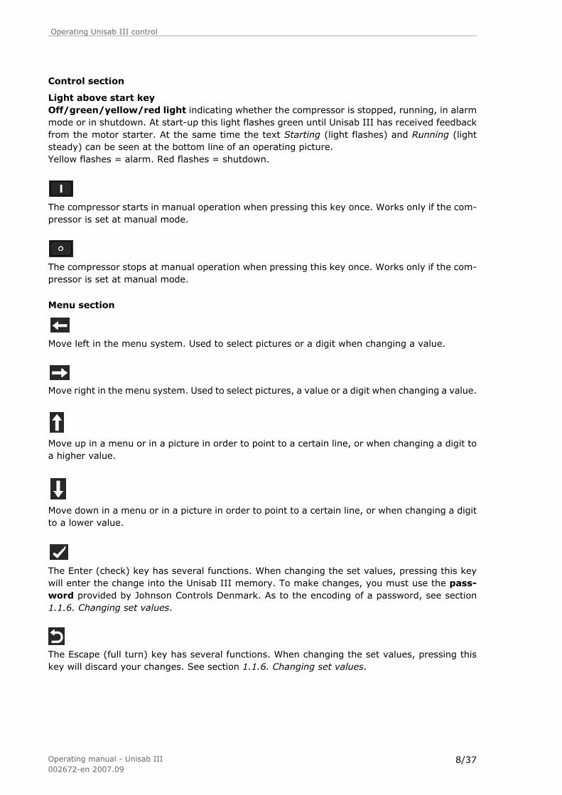
Control section
Light above start keyOff/green/yellow/red light indicating whether the compressor is stopped, running, in alarmmode or in shutdown. At start-up this light flashes green until Unisab III has received feedbackfrom the motor starter. At the same time the text Starting (light flashes) and Running (lightsteady) can be seen at the bottom line of an operating picture.Yellow flashes = alarm. Red flashes = shutdown.
The compressor starts in manual operation when pressing this key once. Works only if the com-pressor is set at manual mode.
The compressor stops at manual operation when pressing this key once. Works only if the com-pressor is set at manual mode.
Menu section
Move left in the menu system. Used to select pictures or a digit when changing a value.
Move right in the menu system. Used to select pictures, a value or a digit when changing a value.
Move up in a menu or in a picture in order to point to a certain line, or when changing a digit toa higher value.
Move down in a menu or in a picture in order to point to a certain line, or when changing a digitto a lower value.
The Enter (check) key has several functions. When changing the set values, pressing this keywill enter the change into the Unisab III memory. To make changes, you must use the pass-word provided by Johnson Controls Denmark. As to the encoding of a password, see section1.1.6. Changing set values.
The Escape (full turn) key has several functions. When changing the set values, pressing thiskey will discard your changes. See section 1.1.6. Changing set values.
Operating Unisab III control
Operating manual - Unisab III002672-en 2007.09
8/37

F-key section
Function key 1. Has several functions, eg bringing the menu to the display.
Function key 2. Has several functions, eg increasing capacity during manual operation.
Function key 3. Has several functions, eg decreasing capacity during manual operation.
Function key 4. Has several functions, eg shutdown reset.
The function of each key will always be shown in the display above the key.
1.1.4. Menu structureUnisab III includes a number of different pictures for compressor operation, set values, config-uration, etc. These pictures are built up in a menu system where a certain picture can be selectedby means of the arrow keys. The menu tree shows the structure and the number of pictures inthe menu systems for:
- Screw compressors
- Single-stage reciprocating compressors
- Two-stage reciprocating compressors
In the menu tree, the selection of pictures is carried out by means of the arrow keys on the frontpanel.
The and keys allow you to move left or right in the menu tree.
The and keys allow you to move up or down in the menu tree by moving the dark cursorfrom line to line.
Press /MENU to get to the main menu consisting of the following menus:
• Favourites - a number of user definable operational pictures
• Alarm - list of active alarms
• Shutdown - list of active shutdowns
• Control values - all operational values with limits and set points
• History - historical shutdown information
• Service - maintenance and diagnosis information
• Setup - all compressor set up, configuration, timers, session etc.
Operating Unisab III control
Operating manual - Unisab III002672-en 2007.09
9/37

Unisab III HMI menu tree
Bold text = menuNormal text = a selectable picture
Menu level 1 Menu level 2 Menu level 3 Menu level 4
Favourites Default
User 1
User 2
User 3
User 4
User 5
User 6
Manage
favourites
Alarms
Shutdown
Control values Suction Values
Pressure Bar
Pressure Deg.
Temperature
Superheat
Limits
Control
Limits
Control
Limits
Control
Limits
Control
Table 1: Unisab III HMI menu tree
Operating Unisab III control
Operating manual - Unisab III002672-en 2007.09
10/37

Menu level 1 Menu level 2 Menu level 3 Menu level 4
Control values Discharge Values
Pressure Bar
Pressure Deg.
Temperature
Superheat
Limits
Control
Limits
Control
Limits
Control
Limits
Control
Oil Values
Pressure
Filter
pressure
Temperature
Separator temp.
Limits
Control
Limits (screws only)
Control
Limits
Control
Limits (UniScrew only)
Control
Motor Values
Current
Power
Revolutions
Limits
Control
Limits
Control
Limits (VFD only)
Control
Capacity Values
Capacity
Cap. slide pos.
Vi slide pos.
Yield
Control (Not VFD)
(Not recip.)
Control (Auto Vi only)
Table 2: Unisab III HMI menu tree
Operating Unisab III control
Operating manual - Unisab III002672-en 2007.09
11/37
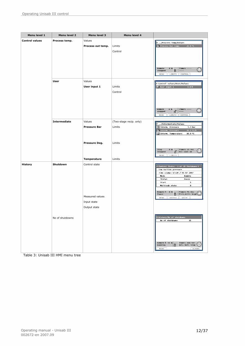
Menu level 1 Menu level 2 Menu level 3 Menu level 4
Control values Process temp. Values
Process out temp. Limits
Control
User Values
User input 1 Limits
Control
Intermediate Values
Pressure Bar
Pressure Deg.
Temperature
(Two-stage recip. only)
Limits
Limits
Limits
History Shutdown
No of shutdowns
Control state
Measured values
Input state
Output state
Table 3: Unisab III HMI menu tree
Operating Unisab III control
Operating manual - Unisab III002672-en 2007.09
12/37

Menu level 1 Menu level 2 Menu level 3 Menu level 4
Service Maintenance Service timers
Diagnosis Hardware
Software
Analog inputs
Analog outputs
Digital inputs
Digital outputs
Software version
Power on
Zero cap. pos. (screws only)
COP
Proficom
Rotatune piston (rota rec. only)
Sep. velocity (Screws only)
Misc. functions
Superuser password
Examine all parameters
Setup Compr. Control
Sequencing
Table 4: Unisab III HMI menu tree
Operating Unisab III control
Operating manual - Unisab III002672-en 2007.09
13/37

Menu level 1 Menu level 2 Menu level 3 Menu level 4
Configuration Drive
Compressor Block
Plant
Oil system
Communication
Dig. in via Profibus
Measuring
External input
Aux. output
Aux. limits
R000
Calibration
Factory reset
(If Profibus Yes)
(If Aux output)
Pressure
Process temperature
Position
Frequency
Analog input
Analog output
Digital input
Digital output
Timers Timer list
Timer setup
Date - Time
Oil charging
Motor fan
P band factor
Transfer
Take-over
(Recip./Screw)
(Recip./Screw)
(Screws only)
(VFD only)
(Recip. only)
(Recip. only)
Table 5: Unisab III HMI menu tree
Operating Unisab III control
Operating manual - Unisab III002672-en 2007.09
14/37
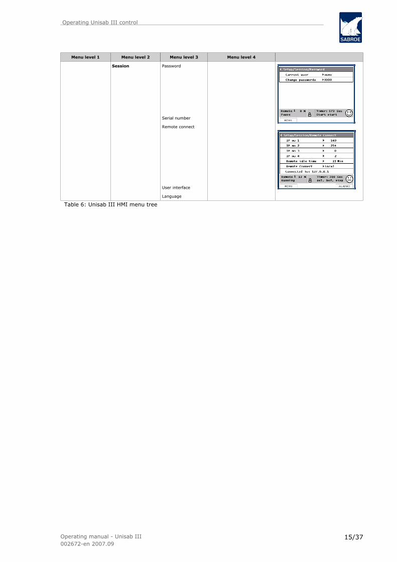
Menu level 1 Menu level 2 Menu level 3 Menu level 4
Session Password
Serial number
Remote connect
User interface
Language
Table 6: Unisab III HMI menu tree
Operating Unisab III control
Operating manual - Unisab III002672-en 2007.09
15/37

1.1.5. SessionWhen selecting the menu Session, the following picture appears:
Fig. 5: Session menu
Password
When you want to change a parameter you must enter a four digit password.
In Unisab III there are 4 password levels:
• Monitoring (no password) - monitoring access only
• User - access to change set points linked to normal operation
• Superuser - access to change configuration and critical set points
• Supervisor - Johnson Controls Denmark supervisor level
Switch between the password levels with and . Choose the appropriate level with andenter the four digit password using the arrow keys. When you have entered the four digits, press
and then /OK.
If the password is accepted you will return to the picture where you wanted to change a pa-
rameter and may change the parameter value with the and keys.
In section 1.1.6. Changing set values, you will find a detailed example of how to change a pa-rameter, eg a limit value.
You can always log into Unisab III even if you are not prompted for a password. Simply chooseCurrent user in the Password picture in the Session menu.
Operating Unisab III control
Operating manual - Unisab III002672-en 2007.09
16/37

You may change the predefined password for a password level. Choose Change passwords inthe Password picture in the Session menu. Log in at the level where you want to change yourpassword and enter your new password. Make sure you remember your new password as youwill need to contact Johnson Controls Denmark in order to have the password re-established ifyou forget it.
User interface
The user interface appearance can be changed (see section 1.1.6. Changing set values). Thismay be carried out even when the compressor is running.
Menu Auto Expand. If this feature is set to “No” the automatic expansion and collapse of themenu tree will be disabled. The menu system will no longer automatically open to a lower menulevel or close a lower level when you continue to the next higher level.
Menu Auto Continue. If this feature is set to “No” you will not automatically continue from alower level menu into the next higher level menu, without using the level up (left) arrow key.
Languages
Like any other function setting (see section 1.1.6. Changing set values) the language can bechanged to any of the following, even when the compressor is running:
en=English fi=Finnish fr=French es=Spanish da=Danish de=German cs=Czechsv=Swedish ru=Russian pl=Polish pt=Portuguese nl=Dutch it=Italian no=Norwegianhu=Hungarian el=Greek tr=Turkish
When Unisab III is switched on for the first time the set language will be English (en).
Operating Unisab III control
Operating manual - Unisab III002672-en 2007.09
17/37

1.1.6. Changing set valuesThis example illustrates how to change set values, ie alarm limits, shutdown limits, set points,timer starting value etc. First you must position the (dark) cursor on the value you want tochange. In this example it is the low shutdown limit for suction pressure. Proceed as follows:
In the menu illustrated below, move the cursor to Control values with the and keys. Press to go to Suction and once again to go to (suction) Values and again to get to the Suction/
Values picture.
In the next picture, move the cursor down to Suction pressure with the key and then press
/LIMITS to get to the (suction) limits picture.
Press four times to get to the Low shutdown value.To change the low shutdown limit, press .
You must enter a password to continue. To change this low shutdown limit you must choose aSuperuser (or higher level) password.
Operating Unisab III control
Operating manual - Unisab III002672-en 2007.09
18/37

Switch between the password levels with the and keys. When you have selected the ap-propriate level with the key, you must enter in this case the four digit Superuser passwordusing the arrow keys.
When you have entered the four digits, press and /OK.
If the password is accepted, you are now back in the Suction pressure limits picture and may
change the Low shutdown limit with the and keys.
When you have set the limit value, press to store the value in the memory. Before pressing
you have the possibility to undo the parameter change by pressing instead of . By doingso, the changes you have just made will not be stored in the memory.
Operating Unisab III control
Operating manual - Unisab III002672-en 2007.09
19/37
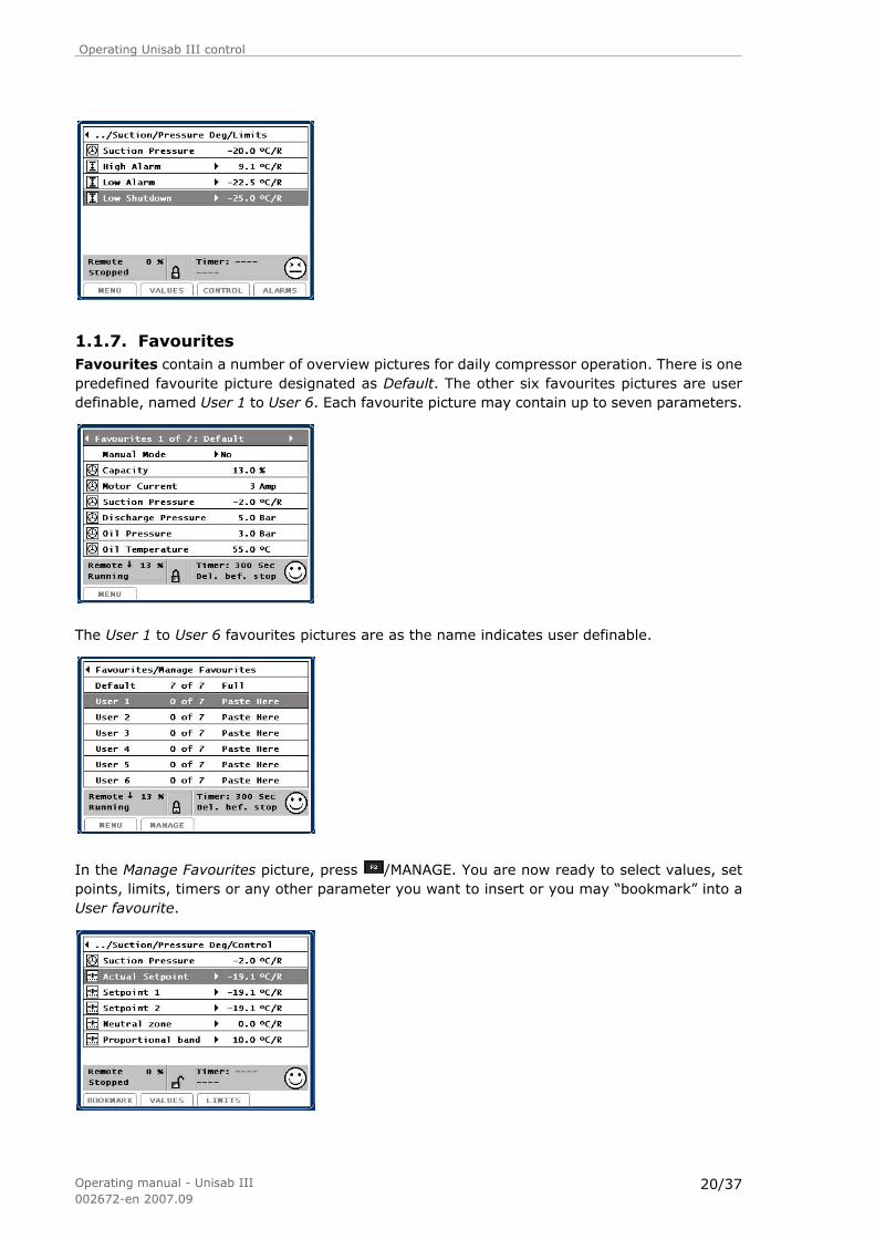
1.1.7. FavouritesFavourites contain a number of overview pictures for daily compressor operation. There is onepredefined favourite picture designated as Default. The other six favourites pictures are userdefinable, named User 1 to User 6. Each favourite picture may contain up to seven parameters.
The User 1 to User 6 favourites pictures are as the name indicates user definable.
In the Manage Favourites picture, press /MANAGE. You are now ready to select values, setpoints, limits, timers or any other parameter you want to insert or you may “bookmark” into aUser favourite.
Operating Unisab III control
Operating manual - Unisab III002672-en 2007.09
20/37

Place the cursor on the value you want to insert from (almost) any picture, eg a suction pressure
set point, and press /BOOKMARK.
Unisab III automatically skips back to the Manage Favourites picture. In this picture, place thecursor on the user picture you want to insert the value into, eg. the User 1 favourite. Press
/CONFIRM to insert the actual setpoint into User 1.
Press /OK to continue bookmarking. Repeat this operation up to seven times, ie until theUser 1 picture is full as shown below.
You can change the order of the parameters by using the arrow keys to move parameters up
and down in the User 1 picture. When satisfied with the order, press /DONE in the ManageFavourites picture to terminate.
1.1.8. Manual and auto operation
Select compressor control mode
Compressor control mode, ie Stopped, Manual, Auto or Remote operation, is selected in theSetup menu in the Compr Control picture.
Operating Unisab III control
Operating manual - Unisab III002672-en 2007.09
21/37

Alternate between manual and auto/remote control mode
In the Default or any User favourites picture (if set up by the user) you may set Manual Modeto “Yes”, ie switch from remote or auto to manual operation. You can always switch betweenManual and Auto/Remote – even during operation.
In Manual operation, the compressor operation (ie starting/stopping and regulating capacity)is entirely controlled by the operator overruled only by the built-in capacity limiters and thealarm/shutdown supervision. In Auto operation, the compressor operation is controlled by thebuilt-in regulator - depending on its configuration during commissioning. In Remote operation,the compressor operation is controlled by a remote regulator/sequence controller - dependingon configuration during commissioning. The built-in capacity limiters and the alarm/shutdownsupervision are also active in Auto and Remote.
Manual loading or unloading of capacity
In manual mode and can be used for manual loading or unloading of capacity. Pressing
increases capacity and pressing decreases capacity. All manual compressor operationmust be carried out from one of the seven favourite pictures.
Manual start
In manual mode and if the compressor is ready you can start the compressor by pressing .Compressor status in the info bar will be prelubrication, starting or running depending on com-pressor type. During the starting period the light diode above the start key will flash green. Afterfeedback from the motor starter, the light diode changes to a steady green light.
Manual stop
You can stop the compressor immediately by pressing . Compressor status in the info bar willbe cap. slide down or pause depending on compressor type. The light diode above the start keywill be off.
Operating Unisab III control
Operating manual - Unisab III002672-en 2007.09
22/37

1.1.9. Shutdown and alarm acknowledgement
A compressor shutdown is acknowledged by pressing /RESET. If the cause of shutdown isno longer present the shutdown message will disappear from the shutdown queue. A shutdownstops the compressor immediately and is indicated by quick red flashes in the light diode abovethe start key. An acknowledged shutdown where the alarm cause is still present is indicated byslow red flashes in the light diode.
A compressor alarm is automatically acknowledged when the alarm cause is no longer presentand the alarm message will disappear from the alarm queue. An alarm does not stop the com-pressor. It is indicated by quick yellow flashes in the light diode above the start key.
1.1.10. Factory settingOn delivery Unisab III is preset with factory settings for all appropriate points. Although othervalues may have been entered from factory or after delivery, Unisab III can always be reset toits factory settings. A factory reset affects the following points:
• Alarm and shutdown limits
• Regulator settings
• Timer setup
• Control mode
The factory settings are stated in the tables in the sections Alarm and shutdown, Timers andCompressor regulation (Engineering manual). Before performing a factory reset, always stopthe compressor for safety reasons. Select Setup/Configuration/Factory Reset and change Fac-tory Reset from No to Yes.
Now press and within a few seconds Unisab III will display the Favourites/Default pictureshown in Fig. 1. The reset operation is complete and Unisab III is now restored to its factorysettings. Unisab III must then be adjusted to the actual operating conditions. Remember to fillin the forms for actual settings before making a factory reset. These forms (Settings for UnisabIII 1.00) are included in the back of this manual.
Operating Unisab III control
Operating manual - Unisab III002672-en 2007.09
23/37

1.1.11. Set valuesThe following tables show the different set values for pressures, temperatures and timers re-spectively. The stated values are minimum, maximum and factory settings.
Operating Unisab III control
Operating manual - Unisab III002672-en 2007.09
24/37

1.2. Pressure levels and temperatures
1.2.1. Measured and calculated pressure levels - screws
Measuring Min. Max. Factory Note
Suction pressure(bar)
High shutdownHigh alarmLow alarmLow shutdown
-1.5-1.0-1.0
-9.06.06.0
-5.01.51.0
-3+4+53+4+53+4+5
Discharge pressure(bar)
High shutdownHigh alarmLow alarmLow shutdown
4.03.0-
-1.0
24.022.0
--1.0
16.015.0
--1.0
1+61+6
-1+5
Oil pressure (bar)Calculated valueSAB Mk 1 compressors
Low alarmLow shutdown
1.51.0
6.05.0
4.02.5
2+72+7
Oil pressure (bar)Calculated valueSAB Mk 2 compressors
Low alarmLow shutdown
0.00.0
6.05.0
0.00.0
2+92+9
Oil pressure (bar)Calculated valueSAB Mk 3, Mk 4 compressorsSAB 202, 283 Mk1, 330, 355Mk1, FV 19, SV 24/26, FV 24/26
Low alarmLow shutdownSet point 1Set point 2
1.00.50.00.0
6.05.010.010.0
1.51.22.54.0
2+92+92121
Oil pressure (bar)Calculated valueVMY Mk 2-2.5 compressor
Low alarmLow shutdown
1.51.0
6.05.0
2.01.5
2+9+172+9+17
Oil pressure (bar)Calculated valueVMY Mk 3 compressors
Low alarmLow shutdownSet point 1Set point 2
1.51.00.00.0
6.05.010.010.0
4.03.05.57.0
2+92+92222
Oil pressure (bar)Calculated valueSAB 120-151 and SAB 193-355
Low alarmLow shutdownSet point 1Set point 2
1.51.00.00.0
6.05.010.020.0
2.01.52.53.0
2+92+92121
Diff. pressureacross oil filter (bar)Calculated valueAll types except SAB 80,SAB 120-151 and SAB 193-355
High shutdownHigh alarm
0.00.0
1.51.3
1.00.7
2+11a2+11a
Diff. pressureacross oil filter (bar)Calculated valueSAB 120-151 and SAB 193-355
High shutdownHigh alarm
0.00.0
4.04.0
1.72.0
2+11b2+11b
Oil pressure (bar)Calculated valueSAB 80
Low alarmLow shutdownSet point 1Set point 2
1.51.00.00.0
6.05.010.020.0
2.01.50.516.0
2+92+92020
Diff. pressureacross oil filter (bar)Calculated valueSAB 80
High shutdownHigh alarm
0.00.0
2.52.5
1.61.4
2+11a+19
2+11a+19
Table 7: Measured and calculated pressure levels - screw compressors
Operating Unisab III control
Operating manual - Unisab III002672-en 2007.09
25/37

1.2.2. Measured and calculated temperatures - screws
Measuring Min. Max. Factory Note
Discharge temperature (°C)
High shutdownHigh alarmLow alarmLow shutdown
60.050.0-65.0
-
130.0120.0-65.0
-
100.090.0-65.0
-
1+61+6
--
Oil temperature (°C)All types except SAB 120-151and SAB 193-355
High shutdownHigh alarmLow alarmLow shutdown
40.030.010.00.0
80.070.050.040.0
65.060.025.020.0
2+72+72+72+7
Oil temperature (°C)SAB 120-151 and SAB 193-355
High shutdownHigh alarmLow alarmLow shutdown
40.030.010.00.0
110.0110.050.040.0
75.070.025.020.0
2+72+72+72+7
Oil separator temperatureSAB 120-151 and SAB 193-355
High shutdownHigh alarmLow alarmLow shutdown
40.030.00.00.0
80.070.050.040.0
65.060.015.010.0
Process out temperature (°C)
High shutdownHigh alarmLow alarmLow shutdown
-60.0-60.0-100.0-100.0
100.0100.0100.0100.0
60.050.04.02.0
1+61+61+61+6
Suction gas superheat (°C)Calculated value
High shutdownHigh alarmLow alarmLow shutdown
6.05.50.00.0
120.0120.040.040.0
110.0100.02.00.0
2+7+122+7+122+7+102+7+10
Discharge gas superheat (°C)Calculated value
Low alarmLow shutdownSet point 1Set point 2
5.00.00.00.0
40.040.0999.9999.9
10.00.05.010.0
2+7+102+7+10
2323
Table 8: Measured and calculated temperatures - screw compressors
Measuring Min. Max. Factory Note
User input 1(4-20 mA)
High shutdownHigh alarmLow alarmLow shutdown
-999.9-999.9-999.9-999.9
999.9999.9999.9999.9
0.00.00.00.0
3+183+183+183+18
Table 9: 4-20 m User input 1 signal
Operating Unisab III control
Operating manual - Unisab III002672-en 2007.09
26/37
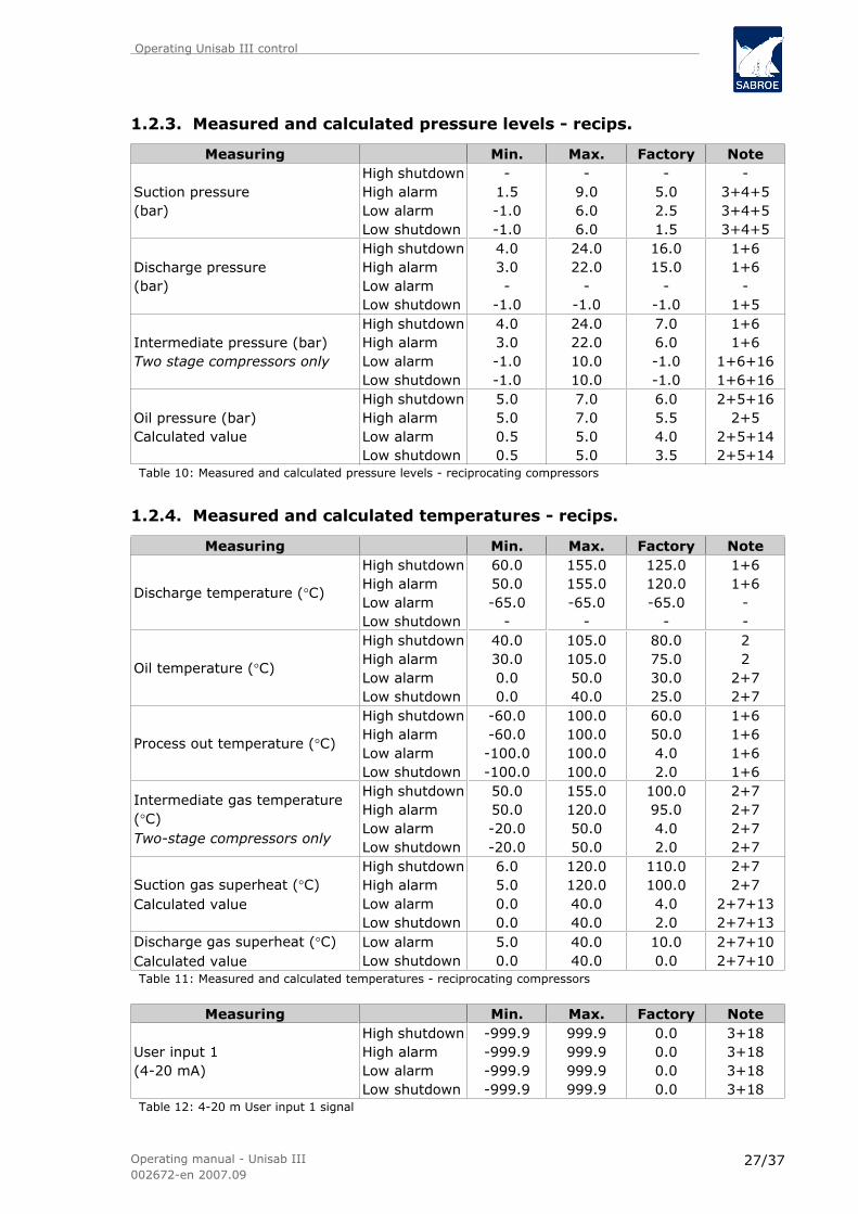
1.2.3. Measured and calculated pressure levels - recips.
Measuring Min. Max. Factory Note
Suction pressure(bar)
High shutdownHigh alarmLow alarmLow shutdown
-1.5-1.0-1.0
-9.06.06.0
-5.02.51.5
-3+4+53+4+53+4+5
Discharge pressure(bar)
High shutdownHigh alarmLow alarmLow shutdown
4.03.0-
-1.0
24.022.0
--1.0
16.015.0
--1.0
1+61+6
-1+5
Intermediate pressure (bar)Two stage compressors only
High shutdownHigh alarmLow alarmLow shutdown
4.03.0-1.0-1.0
24.022.010.010.0
7.06.0-1.0-1.0
1+61+6
1+6+161+6+16
Oil pressure (bar)Calculated value
High shutdownHigh alarmLow alarmLow shutdown
5.05.00.50.5
7.07.05.05.0
6.05.54.03.5
2+5+162+5
2+5+142+5+14
Table 10: Measured and calculated pressure levels - reciprocating compressors
1.2.4. Measured and calculated temperatures - recips.
Measuring Min. Max. Factory Note
Discharge temperature (°C)
High shutdownHigh alarmLow alarmLow shutdown
60.050.0-65.0
-
155.0155.0-65.0
-
125.0120.0-65.0
-
1+61+6
--
Oil temperature (°C)
High shutdownHigh alarmLow alarmLow shutdown
40.030.00.00.0
105.0105.050.040.0
80.075.030.025.0
22
2+72+7
Process out temperature (°C)
High shutdownHigh alarmLow alarmLow shutdown
-60.0-60.0-100.0-100.0
100.0100.0100.0100.0
60.050.04.02.0
1+61+61+61+6
Intermediate gas temperature(°C)Two-stage compressors only
High shutdownHigh alarmLow alarmLow shutdown
50.050.0-20.0-20.0
155.0120.050.050.0
100.095.04.02.0
2+72+72+72+7
Suction gas superheat (°C)Calculated value
High shutdownHigh alarmLow alarmLow shutdown
6.05.00.00.0
120.0120.040.040.0
110.0100.04.02.0
2+72+7
2+7+132+7+13
Discharge gas superheat (°C)Calculated value
Low alarmLow shutdown
5.00.0
40.040.0
10.00.0
2+7+102+7+10
Table 11: Measured and calculated temperatures - reciprocating compressors
Measuring Min. Max. Factory Note
User input 1(4-20 mA)
High shutdownHigh alarmLow alarmLow shutdown
-999.9-999.9-999.9-999.9
999.9999.9999.9999.9
0.00.00.00.0
3+183+183+183+18
Table 12: 4-20 m User input 1 signal
Operating Unisab III control
Operating manual - Unisab III002672-en 2007.09
27/37

1.2.5. Measured/calculated pressure levels/temp. - HPO/HPC
Measuring Min. Max. Factory Note
Suction pressure(bar)
High shutdownHigh alarmLow alarmLow shutdown
-1.5-1.0-1.0
-25.025.025.0
-10.03.52.5
-3+4+53+4+53+4+5
Discharge pressure(bar)
High shutdownHigh alarmLow alarmLow shutdown
4.03.0-
-1.0
40.040.0
--1.0
35.033.0
--1.0
1+61+6
-1+5
Oil pressure (bar)Calculated value
High shutdownHigh alarmLow alarmLow shutdown
5.05.00.50.5
7.07.05.05.0
6.05.54.03.5
2+72+7
--
High diff. pressurePc - Pe (bar)Calculated value
High shutdownHigh alarm
--
--
26.025.2
1+15-
Discharge temperature(°C)
High shutdownHigh alarmLow alarmLow shutdown
60.050.0-65.0
-
170.0170.0-65.0
-
160.0155.0-65.0
-
1+61+6
--
Oil temperature(°C)
High shutdownHigh alarmLow alarmLow shutdown
40.030.00.00.0
105.0105.070.070.0
80.075.020.015.0
2+242+24
2+7+242+7+24
Process out temperature(°C)
High shutdownHigh alarmLow alarmLow shutdown
-20-20-20-20
100.0100.0100.0100.0
75.070.04.02.0
1+61+61+61+6
Suction gas superheat(°C)Calculated value
High shutdownHigh alarmLow alarmLow shutdown
6.05.00.00.0
120.0120.040.040.0
110.0100.04.02.0
2+72+7
2+10+132+10+13
Discharge gas superheat(°C)Calculated value
Low alarmLow shutdown
5.00.0
40.040.0
10.00.0
2+7+102+7+10
Table 13: Measured and calculated pressure levels and temperatures - HPO/HPC
Measuring Min. Max. Factory Note
User input 1(4-20 mA)
High shutdownHigh alarmLow alarmLow shutdown
-999.9-999.9-999.9-999.9
999.9999.9999.9999.9
0.00.00.00.0
3+183+183+183+18
Table 14: 4-20 mA User input 1 signal
Operating Unisab III control
Operating manual - Unisab III002672-en 2007.09
28/37

1.2.6. Notes
Note 1 Shutdown cannot be switched off until the problem has been solved.
Note 2 Shutdown can be switched off immediately ( /RESET key).
Note 3 Shutdown is switched off automatically.
Note 4 Safety limits can be entered in bar or °C/R.
Note 5 Shutdown monitoring active when digital output "compressor starting signal" hasbeen selected.
Note 6 Shutdown monitoring always active - except when Blocked has been selected inthe picture Compressor ctrl mode.
Note 7 Shutdown monitoring delayed 300 sec. after compressor start.
Note 8 Shutdown monitoring delayed 180 sec. after compressor start.
Note 9 Shutdown monitoring delayed 45 sec. after compressor start.
Note 10 A 0.0 setting prevents monitoring.
Note 11a 300 sec. delay, regardless of when limits are exceeded.
Note 11b 600 sec. delay, regardless of when limits are exceeded.
Note 12 The compressor must have been above 5% capacity.When below 5% capacity monitoring is prevented.
Note 13 Shutdown monitoring delayed 15 sec. after compressor start.
Note 14 60 sec. delay, regardless of when limits are exceeded.
Note 15 HPO and HPC compressors only.
Note 16 Shutdown monitoring delayed 20 sec. after compressor start.
Note 17 For VMY Mk 2-2.5, calculate the following: (see Fig. 6) Oil pressure = Oil pressure3 (after oil filter) - Discharge pressure 2. For all other compressor types (exceptSAB 80, see Note 20), calculate the following: Oil pressure = Oil pressure 3 (afteroil filter) - Suction pressure 1.
Note 18 The limits are not active until Ext. inp. s. has been selected in the menu Setup /Configuration/External input.
Note 19 For SAB 80 the differential pressure across the oil filter is calculated as follows:(see Fig. 6) Oil filter diff. pressure = Discharge pressure 2 - Oil pressure 4 (afteroil filter).The stated oil filter pressure will thus be 0.1 to 0.7 bar higher than the actualpressure loss across the filter due to the pressure loss across the oil separator andthe oil cooler.
Operating Unisab III control
Operating manual - Unisab III002672-en 2007.09
29/37

The maximum allowed pressure drop across the oil filter is 1.2 bar. Consequently,the alarm limit should be set between 0.8 and 1.4 bar or lower. The shutdown limitshould be set between 1.1 and 1.7 bar or lower.
Note 20 Set points 1 and 2 are used for shutdown monitoring of the mechanical oil pump,see Engineering manual. For SAB 80, the oil pressure is calculated as follows: (seeFig. 6) Oil pressure = Oil pressure 3 (after pump) - Suction pressure 1.
Note 21 The set points are only used if the compressor is equipped with an electrical oilpump. The set points are used to control the oil pump. When the differential pres-sure falls below set point 1, the oil pump will start. When the differential pressureexceeds set point 2 for 60 seconds, the oil pump will stop.
Note 22 The set points are used to control the full flow pump. When the pressure falls belowset point 1, the full flow pump will start. When the pressure exceeds set point 2for 60 seconds, the full flow pump will stop.
Note 23 The set points are used for liquid slugging, alarm and shutdown. This alarm/shut-down is released by a sudden decrease in discharge temperature which is greaterthan the liquid slugging alarm/shutdown set point for a fixed 5-second period. Setpoint 1 = alarm set point. Set point 2 = shutdown set point.
Note 24 Oil temperature settings on heat pumps should be increased to:High shutdown: 95High alarm: 90Low alarm: 55Low shutdown: 50
Note 25 For SABCube, the differential pressure across the oil filter is calculated as follows:(see Fig. 6): Oil filter diff.pressure = Discharge pressure 2 - Oil pressure 3 (afteroil filter). The shown oil filter pressure will thus be 0.1 to max. 0.5 bar higher thanthe actual pressure loss across the filter due to the pressure loss across the oilseparator and the oil cooler.
Operating Unisab III control
Operating manual - Unisab III002672-en 2007.09
30/37

1.2.7. Oil pressure calculations
Oil filter
Oil pump Compressor
Oil separator
Oil cooler
SAB 80
Others
SABCube
Oil pump
Oil filter
Compressor
Oil cooler
Oil separator
Oil filter
Compressor
Oil separator
Oil cooler
Suction pressure
Oil pressure(before compressor)
Discharge pressure
Oil pressure 2(between pump and filter)
Fig. 6: Oil pressure calculations
Operating Unisab III control
Operating manual - Unisab III002672-en 2007.09
31/37
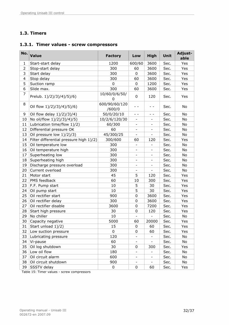
1.3. Timers
1.3.1. Timer values - screw compressors
No.Value Factory Low High Unit
Adjust-able
1 Start-start delay 1200 600/60 3600 Sec. Yes2 Stop-start delay 300 60 3600 Sec. Yes3 Start delay 300 0 3600 Sec. Yes4 Stop delay 300 60 3600 Sec. Yes5 Suction ramp 0 0 1200 Sec. Yes6 Slide max. 300 60 3600 Sec. Yes7
Prelub. 1)/2)/3)/4)/5)/6)10/60/0/6/50/
00 120 Sec. Yes
8Oil flow 1)/2)/3)/4)/5)/6)
600/90/60/120/600/0
- - - - Sec. No
9 Oil flow delay 1)/2)/3)/4) 50/0/20/10 - - - - Sec. No10 No oil/flow 1)/2)/3)/4)/5) 10/2/6/120/30 - - Sec. No11 Lubrication time/flow 1)/2) 60/300 - - Sec. No12 Differential pressure OK 60 - - Sec. No13 Oil pressure low 1)/2)/3) 45/300/25 - - Sec. No14 Filter differential pressure high 1)/2) 300/600 60 120 Sec. Yes15 Oil temperature low 300 - - Sec. No16 Oil temperature high 300 - - Sec. No17 Superheating low 300 - - Sec. No18 Superheating high 300 - - Sec. No19 Discharge pressure overload 300 - - Sec. No20 Current overload 300 - - Sec. No21 Motor start 45 5 120 Sec. Yes22 PMS feedback 60 10 300 Sec. Yes23 F.F. Pump start 10 5 30 Sec. Yes24 Oil pump start 10 5 30 Sec. Yes25 Oil rectifier start 900 0 3600 Sec. Yes26 Oil rectifier delay 300 0 3600 Sec. Yes27 Oil rectifier disable 3600 0 7200 Sec. Yes28 Start high pressure 30 0 120 Sec. Yes29 No chiller 10 - - Sec. No30 Capacity negative 5000 60 20000 Sec. Yes31 Start unload 1)/2) 15 0 60 Sec. Yes32 Low suction pressure 0 0 60 Sec. Yes33 Lubricating pressure 120 - - Sec. No34 Vi-pause 60 - - Sec. No35 Oil log shutdown 30 0 300 Sec. Yes36 Low oil flow 180 - - Sec. No37 Oil circuit alarm 600 - - Sec. No38 Oil circuit shutdown 900 - - Sec. No39 SSSTV delay 0 0 60 Sec. YesTable 15: Timer values - screw compressors
Operating Unisab III control
Operating manual - Unisab III002672-en 2007.09
32/37

Notes
Timer 7
1. For SAB 202, SAB Mk3 and VMY Mk3.
2. For SAB 163 Mk1.
3. For SV 10/20, FV 10/20, SAB 110 SR/LR, SAB 128 HR and SAB 163 HR.
4. For SAB 283 Mk1, SAB 355 Mk1, GSV, RWF and SAB 330 B. (“B” is short for Booster,which can be selected in the Config. menu).
5. For SAB 330 HP. (HP means Booster = No).
6. For SAB 120→151 and SAB 193→355 prelubrication is not used.
Timer 8
1. For SAB 202, SAB Mk3 and VMY Mk3.
2. For SAB 163 Mk1.
3. For SV 10/20 and FV 10/20
4. For SAB 283, SAB 355, GSV, RWF and SAB 330 B. (“B” is short for Booster, which canbe selected in the Config. menu).
5. For SAB 330 HP. (HP means Booster = No).
6. For SAB 120→151 and SAB 193→355 prelubrication is not used.
Timer 9
1. For SAB Mk2 110/128/163, SAB 80 and SABCube.
2. For compressors with prelubrication delay = 0 sec.
3. For SV 10/20 and FV 10/20.
4. SAB 120→151 and SAB 193→355.
Timer 10
1. For SAB 110, 128, 163, 202 and VMY compressors.
2. For SV 10/20 and FV 10/20.
3. For GSV/RWF.
4. For SAB 80.
5. SAB 120→151 and SAB 193→355.
Timer 11
1. For SAB 202, SAB Mk3 and VMY Mk3, SV 10/20 and FV 10/20.
2. For SAB 163 Mk1.
Timer 13
1. For SAB 202, SAB Mk2, SAB Mk3, VMY, SAB 80, SAB 283 Mk1, SAB 355 Mk1, SV 10/20and FV 10/20.
2. For SAB 163 Mk1
3. SAB 120→151 and SAB 193→355.
Operating Unisab III control
Operating manual - Unisab III002672-en 2007.09
33/37

Timer 14
1. For all compressors except SAB 120→151 and SAB 193→355.
2. For SAB 120→151 and SAB 193→355.
Timer 31
1. For FV17/19 and FV25/26.
2. For SAB xxx HR/SABCube.
Operating Unisab III control
Operating manual - Unisab III002672-en 2007.09
34/37

1.3.2. Timer values - reciprocating compressors
No. Value Factory Low High Unit Adjustable1 Start-start delay 1200 600/60 3600 Sec. Yes2 Stop-start delay 300 60 3600 Sec. Yes3 Start delay 300 0 3600 Sec. Yes4 Stop delay 300 5 3600 Sec. Yes5 Suction ramp 0 0 1200 Sec. Yes6 Delay up 600 5 1200 Sec. Yes7 Delay down 60 5 1200 Sec. Yes8 Take-over max. 0 0 3600 Sec. Yes9 Take-over delay 300 300 300 Sec. No10 Intermediate pressure low 20 - - Sec. No11 Filter differential pressure high 300 - - Sec. No12 Total unload 300 - - Sec. No13 Oil pressure low 60 - - Sec. No14 Oil pressure high 20 - - Sec. No15 Oil temperature low 300 - - Sec. No16 Oil temperature high 0 - - Sec. No17 Superheating low 15 15 600 Sec. 1)No 2)Yes18 Superheating high 300 - - Sec. No19 Discharge pressure overload 300 - - Sec. No20 Current overload 300 - - Sec. No21 Motor start 15 5 120 Sec. Yes22 PMS feedback 60 10 300 Sec. Yes23 Oil cooling on 60 60 1500 Sec. Yes24 Oil return 600 0 1200 Sec. Yes25 Oil rectifier start 900 0 3600 Sec. Yes26 Oil rectifier delay 300 0 3600 Sec. Yes27 Oil rectifier disable 3600 0 7200 Sec. Yes28 Start high pressure 30 0 120 Sec. Yes29 No chiller 10 - - Sec. No30 Not used - - - - -31 Not used - - - - -32 Low suction pressure 0 0 60 Sec. Yes33 Not used - - - - -34 Not used - - - - -35 Not used - - - - -36 Not used - - - - -37 Not used - - - - -38 Not used - - - - -39 Not used - - - - -Table 16: Timer values - reciprocating compressors
Notes
1. For discharge superheat
2. For suction superheat
Operating Unisab III control
Operating manual - Unisab III002672-en 2007.09
35/37
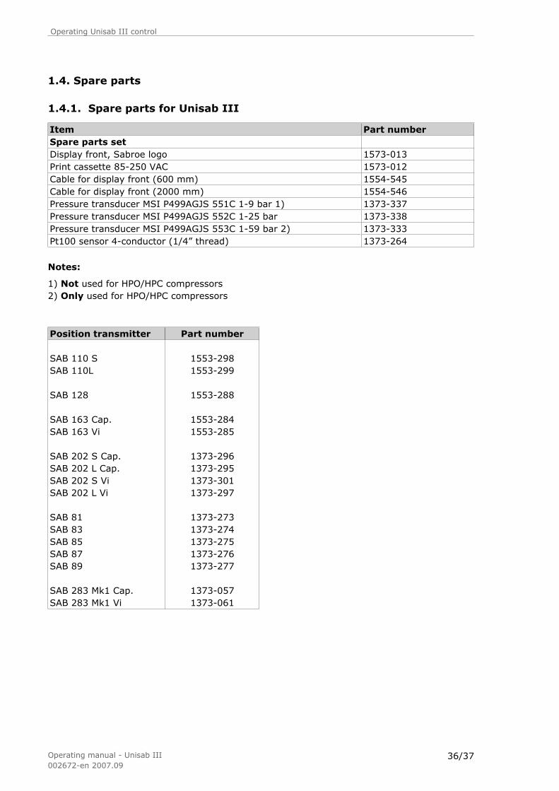
1.4. Spare parts
1.4.1. Spare parts for Unisab III
Item Part numberSpare parts set Display front, Sabroe logo 1573-013Print cassette 85-250 VAC 1573-012Cable for display front (600 mm) 1554-545Cable for display front (2000 mm) 1554-546Pressure transducer MSI P499AGJS 551C 1-9 bar 1) 1373-337Pressure transducer MSI P499AGJS 552C 1-25 bar 1373-338Pressure transducer MSI P499AGJS 553C 1-59 bar 2) 1373-333Pt100 sensor 4-conductor (1/4” thread) 1373-264
Notes:
1) Not used for HPO/HPC compressors2) Only used for HPO/HPC compressors
Position transmitter Part number
SAB 110 S 1553-298SAB 110L 1553-299
SAB 128 1553-288
SAB 163 Cap. 1553-284SAB 163 Vi 1553-285
SAB 202 S Cap. 1373-296SAB 202 L Cap. 1373-295SAB 202 S Vi 1373-301SAB 202 L Vi 1373-297
SAB 81 1373-273SAB 83 1373-274SAB 85 1373-275SAB 87 1373-276SAB 89 1373-277
SAB 283 Mk1 Cap. 1373-057SAB 283 Mk1 Vi 1373-061
Operating Unisab III control
Operating manual - Unisab III002672-en 2007.09
36/37

Position transmitter for new SAB (RWF) compressors
Description SAB 193 SAB 233 SAB 283 SAB 355Capacitytransmitters
Aluminiumtube for LSLinear trans-mitter (2) LS
534D1251H02534D1251H03
534D1251H02534D1251H02
534D1251H02534D1251H02
534D1251H02534D1251H02
Volume trans-mitters
Indicator rodfor SSLinear trans-mitter (1) SS
534C1314H01534C1478H02
534C1314H01534C1478H02
534C1314H02534C1478H02
534C1314H03534C1478H02
(1) Short stroke, without well.Short stroke linear transmitter assembly, with well: 534C1478H01.
(2) Long stroke, without well.Long stroke linear transmitter assembly, with well: 534D1251H01.
Position transmitter for new SAB (XJS, SJF) compressors
Description SAB 120 SAB 151Indicator rod for SS 534B0987H01 534B0872H01Linear transmitter (3) SS 534C1552H02 534C1552H02
(3) Short stroke, without well.Short stroke linear transmitter assembly, with well: 534C1552H01.
Operating Unisab III control
Operating manual - Unisab III002672-en 2007.09
37/37

Page 1/4
Date: __________ Init.: __________
Settings for Unisab III 1.00 Customer: End user: Compressor shop no.: Local compr. no. : ROC no.: Order no.: Plant type: Compressor type: Software version/date:
Set up >Compr. Control Set up >Sequencing
No Function Setting No Function Setting 1 Mode 1 Start no 2 Control On 2 System no 3 Capacity controller 3 System controller 4 Auto Start 5 Auto Stop 6 Cold Store 7 Climate Compensation 8 Multisab master
Setup> Configuration>Calibrate
>Press transducer >Process out Temp. >Position >Motor Freq
Suction Adjust Process out Adj Cap. Pos Motor Freq Discharge Adjust Cap. Zero Ad Frq. Zero Adj Oil Adjust Cap. 100 Adj Freq. 100 Adj Diff./Imed Adjust Vi Position Oil. Adjust Vi. Zero Adj Eco Adjust Vi. 100 Adj

Page 2/4
Settings for Unisab III 1.00
Setup>Configuration >Drive >Oil system >Communication
No. Function Setting No. Function Setting No. Function Setting 1 Motor range Amp 1 Oil pump 1 Compressor 2 Motor range KW 2 Full Flow Pump 2 Baud rate 3 Motor nom kW 3 Oil Cooling 3 Profibus 4 Display 4 Oil controller 4 Profi. node no. 5 Motor input signal 5 Water Cooling 5 Profi. baud rate 6 Rotatune 6 Oil Rectifier 6 GSD file no. 7 Motor rpm min. 7 Sep.Vel.Ref 8 Motor rpm max. 8 Sep.Vel.CR
>Compressor block No. Function Setting >Measuring 1 Compressor Type No. Function Setting 2 Swept Volume 1 Press./Temp. 3 Volume Ratio 2 Pressure range 4 Vi Low Range 3 Low Suct. Press 5 Vi Mode % 4 Capacity signal 6 Mech. Zero 7 Manual Zero >Aux output >Dig. In Via Profibus 8 Booster No. Function Setting No. Function 9 Economizer 1 Activate when 1 Dig. Input 1
10 Eco Low Cap. 2 Signal Low 2 Dig. Input 2 11 Neutral zone 3 Signal High 3 Dig. Input 3 12 Eco High Suction 4 Dig. Input 4 13 Unloading >External (user 1) input 5 Dig. Input 5 14 Unload assist 1 Function 6 Dig. Input 6 15 Cap.decr.assist rate 2 4 mA 7 Dig. Input 7 16 Volume dead band 3 20 mA 8 Dig. Input 8
9 Dig. Input 9 >Plant 10 Dig. Input 10
No. Function Setting 11 Dig. Input 11 1 Refrigerant 12 Dig. Input 12 2 Compressor Setup>Session 13 Dig. input 13 3 Start 1 Language 14 Dig. Input 14 4 System
5 Common Evap/Cond
6 HP on Two Stage 7 High Limit >Factory reset 8 Take Over No. Function Setting 9 COP Active 1 Factory reset
10 Chiller 11 Flow factor 12 Liquid subcool
Setup>Configuration>R000
Temp °C/R Press Bar Temp °C/R Press Bar Temp °C/R Press Bar -90 -30 30 -85 -25 35 -80 -20 40 -75 -15 45 -70 -10 50 -65 -05 55 -60 00 60 -55 05 65 -50 10 70 -45 15 75 -40 20 80 -35 25

Page 3/4
Settings for Unisab III 1.00
Setup>Timers>Timers Setup (1)
No. Function Setting No. Function Setting No. Function Setting Oil Pressure Low (*S) 45/300/25
01 Start-Start Delay
13 Oil Pressure Low (*R) 60
25 Oil Rect. Start
Filter diff high (*S) 300 02 Stop-Start Delay 14 Oil press high (*R) 20
26 Oil Rect. Pause
03 Start Delay 15 Oil Temp Low 300 27 Oil Rect. Disable
04 Stop Delay 16 Oil Temp High 300 0 28 Start HP
05 Suction Ramp 17 Superheat Low 300 15 29 No Chiller 10
Slide Max (*S) 06
Delay Up (*R) 18
Superheat High 300 30 Cap. Negative (*S)
Pre lubrication (*S)
10/60/0/6/50/0 07
Delay Down (*R) 19 Disch Press
O/load 300 31 Start Unload (*S)
Oil Flow (*S)
600/90/60/120/600/0 08
Transfer max (*R) 20 Current Overload 300 32 Low suct. press
Oil Flow Delay (*S) 50/0/20/10
09 Take Over Delay (*R) 300
21 Motor Start
33 Lub Pressure (*S) 145
No Oil Flow (*S)
10/2/6/120/30 10
Interm Press Low (*R) 20
22
PMS Feedback
34 Vi pause (*S) 60
Lub time/flow (*S) 60/300 F.F. Pump
Start(*S) 35 Oil Log Shutdown
(*S) 60 11
Filter Diff High (*R) 300
23 Oil Cool On
(*R) 36 Low Oil Flow (*S) 180
Diff press OK (*S) 60 Oil Pump Start(*S) 37 Oil Cir. Alm (*S) 600 12
Total unload (*R) 24
Oil Return (*R) 38 Oil Cir. Shutdown (*S) 900
39 SSSTV delay
Setup>Timers>P Band Factor (1)
Setup>Timers>Transfer (1)
Setup>Timers>Take Over (1)
Delay Up (*R) Factor Down (*R) Factor Up (*R)
Delay Down (*R) Zone (*R) Factor Start (*R)
Start Delay Zone (*R)
Stop Delay
Setup>Service>Maintenance
Estimated compressor main service
Hour counter
Time to next main service C
Time to next part service B
Time to next part service A

Page 4/4
Settings for Unisab III 1.00
Control values>
Alarm-/Shutdown Limits & Regulator Settings (1)
High Shut down
High Alarm
Low Alarm
Low Shut down
SP No. 1
SP No. 2
NZ PB T. Integ.
T. Diff.
MIN PULS
RUN TIME
Suction>Suction pressure [ºC/R]
Suction>Suction superheat
Discharge>Disch. pressure [ºC/R] Discharge>Disch. Temperature
Discharge>Disch. Superheat
Oil>Oil pressure
Oil>Oil filter pressure (*S)
Oil>Oil temperature
Oil>Oil separator temperature (*S)
Motor>Motor current
Motor>Motor Power
Capacity>Capacity (*S) Capacity>Vi Position (*S) Process temp>Process out temp
User> User input 1
Intermediate>Interm. pres. [ºC/R] (*R) Intermediate>Interm. temperature (*R) Notes: (*S) = Screw, (*R) = Reciprocating (1) The value(s) will be changed to factory settings by a “Factory reset”.

Date: _____________ Init.: _____________
2007.07
Diagnosis for Unisab III
Customer: __________________ Order no.: _____________
Compressor shop no. __________________ Compressor type: _____________
History ► Shutdowns ► Control state Current operating conditions UnitAlarm text(type of alarm)
Text
Date and time of alarm TextCompressor mode TextCompressor status TextStart 0-14Multisab state Text
History ► shutdowns ►Measured values
Currentoperatingconditions
UnitDiagnosis
No. InputOut-put
Digitalinput
Digitaloutput
Suction temp. °C 1 Suction press. °C/R 2 Suctionsuperheat
°C 3
Discharge temp. °C 4 Discharge press. °C/R 5 Dischargesuperheat
°C 6
Oil temp. °C 7 Oil press. Bar 8 Capacity % 9 Vi slide pos. (S) % 10 Motor rev. rpm 11 Motor current Amp. 12 Motor power kW 13 Oil filter press. (S) Bar 14 Process out temp. °C 15 User input 1 % 16 Oil sep. temp. °C 17 Intermediate press.(R)
°C/R 18
Intermediate temp.(R)
°C 19
Notes:(S) = Screw compressors(R) = Reciprocating compressors
1/1