123/145kV SF Gas-Insulated Switchgear incorporating VCB · · 2016-01-18123/145kV SF6...
7
123/145kV SF6 Gas-Insulated Switchgear incorporating VCB 145kV-1250~2000A-31.5kA
Transcript of 123/145kV SF Gas-Insulated Switchgear incorporating VCB · · 2016-01-18123/145kV SF6...
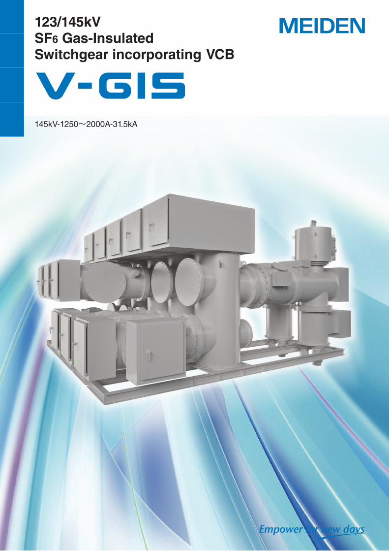
123/145kVSF6 Gas-InsulatedSwitchgear incorporating VCB
145kV-1250~2000A-31.5kA
1. General
Concept
Drastic saving for installation space*1
Highly resistant to adverse environments, high safety
Easy to maintain
Increased reliability by applying VCBNote: *1 comparison with Conventional Substation
Features
145kV single-break vacuum circuit breaker
I. VCB has a extremely low contact erosion and a long service life 1) 10,000 operations at the rated current 2) 30 operations at the rated short-current breaking current
II. Excellent fault current breaking capability against multiple-lightning strikes
III. No decomposed SF6 produced during the current breaking process *Focus on VCB, recorded up to 204kV Live tank Type CB
High quality and reliability
I. Manufactured under Meidensha's time-proven quality control systems
II. Minimum site assembly work required
III. Designed and developed based on many years of Meidensha's technical experience and expertise in design and manufacture of GIS/C-GIS incorporating VCBs
Easy to maintain and Environment-friendly
I. Easy to maintain and a long service life High-quality and long-life grease and O-rings
II. Enviornment-friendly. Minimum use of SF6 gas at a low pressure for insulation only
The circuit breaker technology has evolved along with that of the power systems as their transmission volt-age has become higher and short-circuit capacity has increased. When we summarize this process we see the technology have developed to meet the following new requirements among others: higher transmission voltage in larger short-circuit capacity, higher speed, compactness, improved reliability that reduces mainte-nance requirements, and complexing site requirements.From the perspective of the circuit breaker technology, this is a history of an obsessive quest for a high-insula-tion medium with a superior arc extinguishing capabili-ty. In other words, the fault current breaking conditions have become tougher as the transmission voltage has become higher and networking of power systems have become more common, and circuit breakers must now have among its essential requirements less arc energy
properties and faster insulation recovery capabilities when breaking fault currents.The Vacuum Circuit Breaker (VCB) possesses the most effective insulation medium and the fastest insulation recovery of any type of circuit breakers, and satisfies all fault current breaking requirements.
Additionally, the features unique to the VCB can be summarized as follows.
1. A complete self-extinguishing property that makes the VCB the only breaker capable of handling an evolving fault.
2. Low arc energy property offers a long service life of the contacts.
3. Easy maintenance results in the lowest running (maintenance) cost of any type of breakers.
Of particular interest in Table 1 is that when the ne-cessity of circuit breakers was first conceived, it was considered that the ideal circuit breaker that was arc-free could be made in perfect vacuum and research on this ideal circuit breaker has continued non-stop all the way up to the present.Also, the trend towards an oil-less, arc distinguishing high-insulation medium is evident. That is, development has advanced from oil to compressed air to SF6 gas
and finally to vacuum.Global trends now require circuit breakers that meets the requirements for resource conservation and en-vironmentally friendly performance, and the VCB an-swers these concerns.Against such background and history, Meidensha has constantly been making VCB history and taking the lead in the VCB development. Most recently, we have introduced a GIS incorporating the VCB.
Table 1 summarizes the history of the VCB and important events in the circuit breaker technology.Year VCB development Important events
1890 Patent for arc extinguishing in a vacuum Formation period of the electricity industry, up to 1000V. A combination of fuses and air-break switches
1900 1920
Parallel switching OCBs developed (hydroelectric power at 10kV or above). OCBs explosions were common Arc-extinguishing chamber OCBs developed
1926 Solensen conducts power system experiments and discovers more breaking capacity in vacuum than expected
1930 Cell-type OCBs developedMagnetic blow-out circuit breaker developed
1935 Air-blast circuit breaker developed
1950 GE selects electrode materials and establishes processing tech-nology (Lee, Cobine)
Ultra-high voltage transmission network builtTank OCBs with BCTs developedMulti-break air-blast circuit breaker developedSF6 Gas Circuit Breakers (GCBs) developed (single pressure system)
1960 US based Jennings develops a 10kV-250A vacuum switch
Ultra-extra high voltage transmission systems builtMulti-break minimum-oil OCB developedDual-direction blow nozzle continuous air-charge system resistance air-blast circuit breakers developed
1965 3.6kV / 7.2kV VCB developed (single-break) Dual pressure multi-break GCBs developed
1970 36kV VCB developed (single-break)*
1973 84kV VCB developed (single-break)* 168kV single-break single-pressure GCBs developed
1977 145kV VCB developed (double-break)*
1978 168kV VCB developed (double-break)*
1979 Single-break 120/123kV VI developed*
1989 204kV VCB developed (double-break)*
1995 Miniaturized high-voltage VI* Axial magnetic-field electrode method improves the breaker performanceMiniaturization advances
2002 84kV high-voltage ceramic VI developed* High-voltage vacuum insulated compatible 84kV ceramic VI developed
2010 Advances in 84kV high-voltage ceramic VI miniaturization and increased capacity*
New electrode materials developedAxial magnetic-field vacuum arc optimized
2014 145kV single break ceramic VI developed* Electric field analysis, magnetic field analysis
Note: Items marked with an * indicate that the development for higher voltage applications has been undertaken by Meidensha after 1970.
1 2
2. Technical Specification
Table 2 Gas Insulated Switchgear (GIS)
Model GKS-14V
Rated voltage (kV) 123 145
Rated current (A) 1250/2000
Rated frequency (Hz) 50/60
Rated breaking current (kA) 31.5
Rated short time withstand current (kA-sec) 31.5-3
Insulation level (Between phases, phase to earth)
1min power frequency (kV rms) 230 275
Lightning impulse (kV peak) 550 650
Insulation level (for DS) (Across the isolating dis-tance)
1min power frequency (kV rms) 265 315
Lightning impulse (kV peak) 630 750
Rated control/operating voltage (Vdc) Control voltage: 110 Operating voltage: 110
Rated gas pressure (at 20ºC) SF6 gas insulation
VCB, bus bar 0.16MPa・G
Other 0.5MPa・G
Applicable standards IEC62271-203(2011)
Installation location Indoor/outdoor
Table 3 Vacuum Circuit Breaker (VCB)
Model VBU-120732B
Rated voltage (kV) 123/145
Rated current (A) 1250/2000
Rated breaking current (kA) 31.5
Rated short time withstand current (kA-sec) 31.5-3
Rated making current (kA) 80
Operating duty 0-0.3s-CO-3min-CO
Operating mechanismOpening Spring
Closing Motor charged spring
Applicable standards IEC62271-100(2008)
Table 4 Disconnecting Switch (DS)
Model GDT-120732MA
Rated voltage (kV) 123/145
Rated current (A) 1250/2000
Rated short time withstand current (kA-sec) 31.5-3
Operating mechanism Manual / Motor-drive
Applicable standards IEC62271-102(2003)
Table 5 Maintenance Earthing Switch (ES)
Model GEF-12032HA
Rated voltage (kV) 123/145
Rated short time withstand current (kA-sec) 31.5-3
Operating mechanism Manual
Applicable standards IEC62271-102(2003)
Table 6 High Speed Earthing Switch (HSES)
Model GECF-12032BA
Rated voltage (kV) 123/145
Rated short time withstand current (kA-sec) 31.5-3
Rated making current (kA) 80
Operating mechanism Motor charged spring
Applicable standards IEC62271-102(2003)
3 4
3. Equipment Design
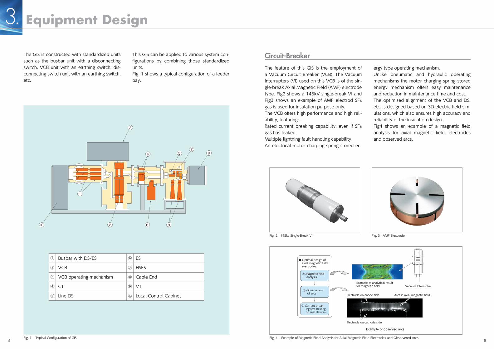
The GIS is constructed with standardized units such as the busbar unit with a disconnecting switch, VCB unit with an earthing switch, dis-connecting switch unit with an earthing switch, etc.
This GIS can be applied to various system con-figurations by combining those standardized units.Fig. 1 shows a typical configuration of a feeder bay.
The feature of this GIS is the employment of a Vacuum Circuit Breaker (VCB). The Vacuum Interrupters (VI) used on this VCB is of the sin-gle-break Axial Magnetic Field (AMF) electrode type. Fig2 shows a 145kV single-break VI and Fig3 shows an example of AMF electrod SF6
gas is used for insulation purpose only.The VCB offers high performance and high reli-ability, featuring:-Rated current breaking capability, even if SF6 gas has leakedMultiple lightning fault handling capabilityAn electrical motor charging spring stored en-
ergy type operating mechanism.Unlike pneumatic and hydraulic operating mechanisms the motor charging spring stored energy mechanism offers easy maintenance and reduction in maintenance time and cost.The optimised alignment of the VCB and DS, etc. is designed based on 3D electric field sim-ulations, which also ensures high accuracy and reliability of the insulation design.Fig4 shows an example of a magnetic field analysis for axial magnetic field, electrodes and observed arcs.
3
57
9
86210
1
4
① Busbar with DS/ES ⑥ ES
② VCB ⑦ HSES
③ VCB operating mechanism ⑧ Cable End
④ CT ⑨ VT
⑤ Line DS ⑩ Local Control Cabinet
Fig. 1 Typical Configuration of GIS
Fig. 2 145kv Single-Break VI Fig. 3 AMF Electrode
Fig. 4 Example of Magnetic Field Analysis for Axial Magnetic Field Electrodes and Observered Arcs.
Circuit-Breaker
Electrode on cathode side
Electrode on anode side Arcs in axial magnetic field
● Optimal design of axial magnetic fieldelectrodes
① Magnetic field analysis
Example of analytical resultfor magnetic field
Example of observed arcs
Vacuum Interrupter② Observation of arcs
③ Current break- ing test (testing on real device)
5 6
Name of unit
Circuit-breaker unit
Rated gas pressure(MPa・g)
Alarm gas Pressure(MPa・g)
0.14
GAS PRESSURE (at 20℃)
Busbar unit0.16 0.140.16
0.45Others 0.50
DS
ES
VCB
CT
ES
DS
ES
CH
VT
Stop valve (Normally open)
Stop valve (Normally close)
GAS BOUNDARY SYMBOLS
Gas supply inlet
Gas density monitorwith temperature compensation
Gas sealing spacer
3. Equipment Design
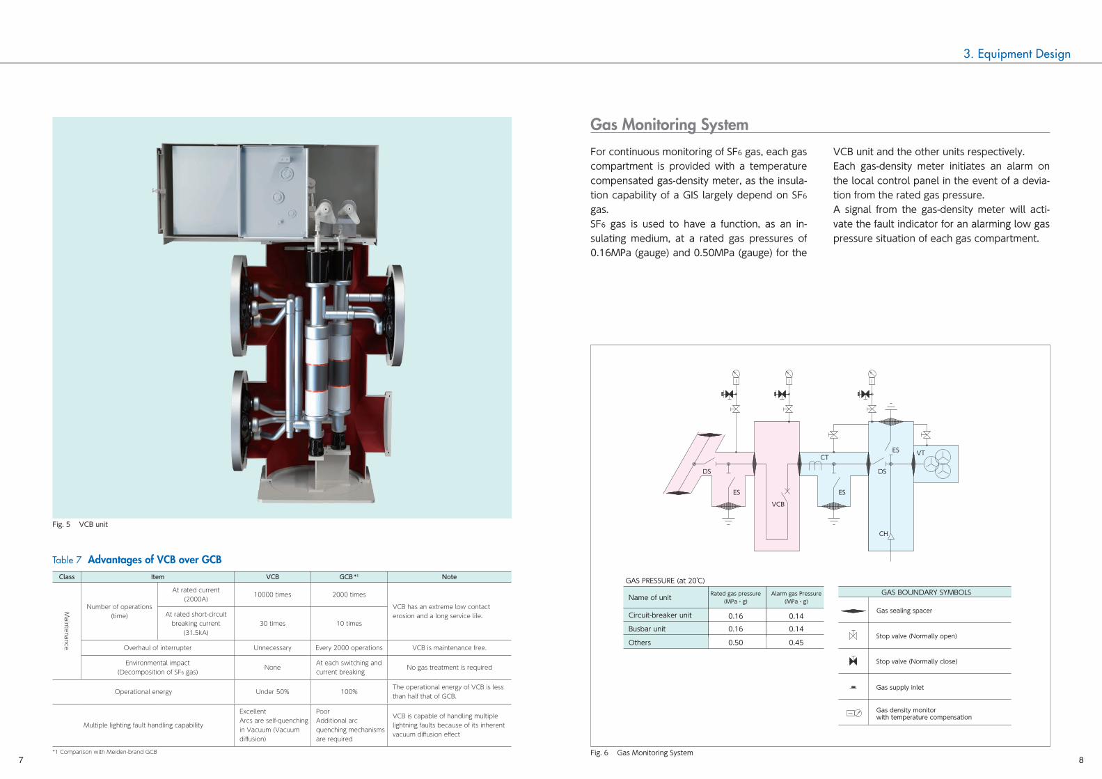
Table 7 Advantages of VCB over GCBClass Item VCB GCB *1 Note
Maintenance
Number of operations (time)
At rated current(2000A)
10000 times 2000 times
VCB has an extreme low contact erosion and a long service life.At rated short-circuit
breaking current(31.5kA)
30 times 10 times
Overhaul of interrupter Unnecessary Every 2000 operations VCB is maintenance free.
Environmental impact(Decomposition of SF6 gas)
NoneAt each switching and current breaking
No gas treatment is required
Operational energy Under 50% 100%The operational energy of VCB is less than half that of GCB.
Multiple lighting fault handling capability
ExcellentArcs are self-quenching in Vacuum (Vacuum diffusion)
PoorAdditional arc quenching mechanisms are required
VCB is capable of handling multiple lightning faults because of its inherent vacuum diffusion effect
*1 Comparison with Meiden-brand GCB
Fig. 5 VCB unit
Fig. 6 Gas Monitoring System
Gas Monitoring System
For continuous monitoring of SF6 gas, each gas compartment is provided with a temperature compensated gas-density meter, as the insula-tion capability of a GIS largely depend on SF6 gas.SF6 gas is used to have a function, as an in-sulating medium, at a rated gas pressures of 0.16MPa (gauge) and 0.50MPa (gauge) for the
VCB unit and the other units respectively.Each gas-density meter initiates an alarm on the local control panel in the event of a devia-tion from the rated gas pressure.A signal from the gas-density meter will acti-vate the fault indicator for an alarming low gas pressure situation of each gas compartment.
7 8
4. Maintenance
All live parts in SF6 Gas Insulated Switchgear are not affected by external environmental con-ditions such as air pollution, excessive mois-ture, salty air, etc.Therefore, no inspection/maintenance for equipment/devices inside the SF6 gas compart-ments is usually required until the number of operations of a switching device reaches to the specified number of operations.Only external inspection/maintenance such as checking of gas pressure monitors, greasing of the operating mechanism, etc. is normally re-quired without opening the gas compartments.On the other hand, the contents of inspection /maintenance vary depending upon the operati-ing conditions, thus, the frequency and type of inspections needs to be determined to suit the operating conditions.
Recommended inspection/maintenance:(1) In the Routine Inspection, which is recom-
mended to be made every six (6) years, each SF6-gas-filled area should be checked and confirmed that the specified gas pres-sure is maintained. Also, an operating char-acteristic test of the operating mechanism must be done.
(2) In the Periodic Inspection, which is rec-ommended to be made every twelve (12) years, the same inspection as the above routine inspection should be done and any worn parts should be replaced with new parts.
(3) A special inspection must be made when a fault is found, and when the specified max-imum number of operations is reached. It is recommended to make inspection/mainte-nance on primary components such as the VCB when 30 times of full fault current inter-ruptions is reached, and the DS when 2000 times of mechanical operations is reached.
Details of inspections/maintenance are described in the instruction manual.
Table 8 Recommended inspection/maintenance
Type of inspection Frequency ofInspection What is to be made in inspection / maintenance
Patrol inspection Daily External visual inspection with the breaker being kept in service.
Routine inspection Every six (6) years
The GIS must be taken out of service before inspection/maintenance is carried out.・Operating mechanism check・Operating characteristic test of the operating mechanism・External inspection
Periodic inspection Every twelve (12) years
The GIS must be taken out of service before inspection/maintenance is carried out.・Operating mechanism check・Operating characteristic test of the operating mechanism・External inspection・Replacement of worn parts with new ones, such as door-sealing packings etc.
Special inspection
When the spec-ified maximum number of opera-tion is reached
Before starting inspection, ensure to:・Take out the GIS out of service・Evacuate SF6 gas・Open the gas compartment・Dismantle the current breaking section for inspection (Replace the whole parts)・Replace any worn parts with new ones
Life Cycle Cost (LCC)
Maintenance Low Life Cycle Cost !■ Overhaul of Interrupter (Circuit Breaker Portion) VCB is maintenance free.
Item
Overhaul of Interrupter
VCB
VCB GCB*1
UnnecessaryGCB*1
Every 2,000 Operationsor 18th Years
Maintenance schedule (period) of various CB
6th years
12th years
18th years
24th years
30th years
Purpose General General
Routine
Periodic
Routine
Periodic
OverhaulRoutine
Periodic Periodic
End of life
GCB
GCB
VCB
GCB :Overhaul timing
VCB
VCB : Overhaul Unnecessary
Maintenance time interval /year
Mai
nten
ance
Cos
t (Re
lativ
e va
lue
%)
(End of life)6th 12th 18th 24th 30th
0
20
40
60
80
100
120
*1 Comparison with Meiden-brand GCB
Therefore, VCB is superior to the conventional GCB in Labor Cost & Time Saving.
7100
49
50
33
00
5200
VCBES CT
ESDS
VT
HSESVD
LCC
SINGLE LINE DIAGRAM
VD
ESVT
DS
ES
CT
CT
CT
ES
VCB
Fig. 8 Configulation example
Fig. 7 Maintenance cost (VCB and GCB)
9 10
BA89-3263 As of Dec., 20152015-12ME 1L