1212.8 18 EN - KSB
68
Standardised Pump Etachrom L Installation/Operating Manual
Transcript of 1212.8 18 EN - KSB
Standardised Pump
Etachrom L
Installation/Operating Manual

Legal information/Copyright
Installation/Operating Manual Etachrom L
Original operating manual
All rights reserved. The contents provided herein must neither be distributed, copied, reproduced,edited or processed for any other purpose, nor otherwise transmitted, published or made available to athird party without the manufacturer's express written consent.
Subject to technical modification without prior notice.
© KSB SE & Co. KGaA, Frankenthal 19/09/2018

Contents
3 of 68Etachrom L
Contents
Glossary .................................................................................................................................................. 6
1 General.................................................................................................................................................... 71.1 Principles ........................................................................................................................................................... 71.2 Installation of partly completed machinery.................................................................................................... 71.3 Target group..................................................................................................................................................... 71.4 Other applicable documents............................................................................................................................ 71.5 Symbols ............................................................................................................................................................. 71.6 Key to safety symbols/markings....................................................................................................................... 8
2 Safety...................................................................................................................................................... 92.1 General.............................................................................................................................................................. 92.2 Intended use ..................................................................................................................................................... 92.3 Personnel qualification and training............................................................................................................... 92.4 Consequences and risks caused by non-compliance with this manual ....................................................... 102.5 Safety awareness ............................................................................................................................................ 102.6 Safety information for the operator/user ..................................................................................................... 102.7 Safety information for maintenance, inspection and installation .............................................................. 102.8 Unauthorised modes of operation................................................................................................................ 112.9 Explosion protection ...................................................................................................................................... 11
2.9.1 Marking .............................................................................................................................................. 112.9.2 Temperature limits............................................................................................................................. 112.9.3 Monitoring equipment...................................................................................................................... 122.9.4 Operating limits ................................................................................................................................. 12
3 Transport/Temporary Storage/Disposal............................................................................................. 133.1 Checking the condition upon delivery .......................................................................................................... 133.2 Transport......................................................................................................................................................... 133.3 Storage/preservation...................................................................................................................................... 143.4 Return to supplier........................................................................................................................................... 143.5 Disposal ........................................................................................................................................................... 15
4 Description of the Pump (Set) ............................................................................................................. 164.1 General description ........................................................................................................................................ 164.2 Product Information as per Regulation No. 547/2012 (for water pumps with a maximum shaft power of
150 kW) implementing "Ecodesign" Directive 2009/125/EC........................................................................ 164.3 Designation..................................................................................................................................................... 164.4 Name plate...................................................................................................................................................... 184.5 Design details.................................................................................................................................................. 184.6 Configuration and function........................................................................................................................... 204.7 Noise characteristics ....................................................................................................................................... 204.8 Scope of supply............................................................................................................................................... 214.9 Dimensions and weights ................................................................................................................................ 21
5 Installation at Site ................................................................................................................................ 225.1 Checks to be carried out prior to installation............................................................................................... 225.2 Installing the pump set .................................................................................................................................. 22
5.2.1 Installation on the foundation.......................................................................................................... 235.2.2 Installation without foundation ....................................................................................................... 24
5.3 Piping .............................................................................................................................................................. 245.3.1 Connecting the piping....................................................................................................................... 245.3.2 Permissible forces and moments at the pump nozzles.................................................................... 265.3.3 Vacuum balance line.......................................................................................................................... 27
5.4 Enclosure/insulation ....................................................................................................................................... 275.5 Checking the coupling alignment ................................................................................................................. 285.6 Aligning the pump and motor ...................................................................................................................... 29
5.6.1 Motors with adjusting screw............................................................................................................. 29
Contents
4 of 68 Etachrom L
5.6.2 Motors without adjusting screw....................................................................................................... 305.7 Electrical connection ...................................................................................................................................... 31
5.7.1 Setting the time relay ........................................................................................................................ 315.7.2 Earthing .............................................................................................................................................. 315.7.3 Connecting the motor ....................................................................................................................... 32
5.8 Checking the direction of rotation................................................................................................................ 32
6 Commissioning/Start-up/Shutdown................................................................................................... 336.1 Commissioning/Start-up................................................................................................................................. 33
6.1.1 Prerequisites for commissioning/start-up ......................................................................................... 336.1.2 Filling in lubricants............................................................................................................................. 336.1.3 Priming and venting the pump......................................................................................................... 336.1.4 Final check .......................................................................................................................................... 346.1.5 Start-up............................................................................................................................................... 346.1.6 Checking the shaft seal...................................................................................................................... 356.1.7 Shutdown ........................................................................................................................................... 35
6.2 Operating limits.............................................................................................................................................. 366.2.1 Ambient temperature........................................................................................................................ 366.2.2 Frequency of starts............................................................................................................................. 366.2.3 Fluid handled ..................................................................................................................................... 37
6.3 Shutdown/storage/preservation .................................................................................................................... 386.3.1 Measures to be taken for shutdown ................................................................................................ 38
6.4 Returning to service ....................................................................................................................................... 38
7 Servicing/Maintenance........................................................................................................................ 407.1 Safety regulations........................................................................................................................................... 407.2 Servicing/Inspection........................................................................................................................................ 41
7.2.1 Supervision of operation ................................................................................................................... 417.2.2 Inspection work.................................................................................................................................. 437.2.3 Lubrication and lubricant change of rolling element bearings ...................................................... 44
7.3 Drainage/cleaning .......................................................................................................................................... 457.4 Dismantling the pump set.............................................................................................................................. 46
7.4.1 General information/Safety regulations........................................................................................... 467.4.2 Preparing the pump set..................................................................................................................... 477.4.3 Removing the motor.......................................................................................................................... 477.4.4 Removing the back pull-out unit ...................................................................................................... 477.4.5 Removing the impeller ...................................................................................................................... 477.4.6 Removing the mechanical seal.......................................................................................................... 487.4.7 Dismantling the bearings .................................................................................................................. 48
7.5 Reassembling the pump set ........................................................................................................................... 487.5.1 General information/Safety regulations........................................................................................... 487.5.2 Fitting the bearings ........................................................................................................................... 497.5.3 Installing the mechanical seal ........................................................................................................... 497.5.4 Fitting the impeller ............................................................................................................................ 507.5.5 Installing the back pull-out unit ....................................................................................................... 517.5.6 Mounting the motor ......................................................................................................................... 51
7.6 Tightening torques......................................................................................................................................... 527.6.1 Tightening torques for the pump..................................................................................................... 527.6.2 Tightening torques for the pump set ............................................................................................... 53
7.7 Spare parts stock............................................................................................................................................. 547.7.1 Ordering spare parts.......................................................................................................................... 547.7.2 Recommended spare parts stock for 2 years' operation to DIN 24296 .......................................... 557.7.3 Interchangeability of Etachrom L and Etachrom B pump components ......................................... 56
8 Trouble-shooting.................................................................................................................................. 57
9 Related Documents .............................................................................................................................. 599.1 Exploded views with list of components....................................................................................................... 59
9.1.1 Design for shaft unit 25.1.................................................................................................................. 599.1.2 Design for shaft unit 25.2.................................................................................................................. 609.1.3 Design for shaft unit 35..................................................................................................................... 61

Contents
5 of 68Etachrom L
10 EU Declaration of Conformity ............................................................................................................. 62
11 Certificate of Decontamination........................................................................................................... 63
Index ..................................................................................................................................................... 64

Glossary
6 of 68 Etachrom L
Glossary
ACSFrench drinking water regulations (ACS =Attestation de Conformité Sanitaire)
Back pull-out designThe complete back pull-out unit can be pulled outwithout having to remove the pump casing fromthe piping.
Back pull-out unitPump without pump casing; partly completedmachinery
Certificate of decontaminationA certificate of decontamination is enclosed by thecustomer when returning the product to themanufacturer to certify that the product has beenproperly drained to eliminate any environmentaland health hazards arising from components incontact with the fluid handled.
Discharge lineThe pipeline which is connected to the dischargenozzle
Hydraulic systemThe part of the pump in which the kinetic energyis converted into pressure energy
Pool of pumpsCustomers/operators’ pumps which are purchasedand stored regardless of their later use.
PumpMachine without drive, additional components oraccessories
Pump setComplete pump set consisting of pump, drive,additional components and accessories
Suction lift line/suction head lineThe pipeline which is connected to the suctionnozzle
UBAGerman drinking water regulations to GermanEnvironment Agency
WRASApproved by all water suppliers in the UK (WRAS =Water Regulations Advisory Scheme)

1 General
7 of 68Etachrom L
1 General
1.1 PrinciplesThis operating manual is supplied as an integral part of the type series and variantsindicated on the front cover.
The manual describes the proper and safe use of this equipment in all phases ofoperation.
The name plate indicates the type series and size, the main operating data, the ordernumber and the order item number. The order number and order item numberclearly identify the pump set and serve as identification for all further businessprocesses.
In the event of damage, immediately contact your nearest KSB Service centre tomaintain the right to claim under warranty.
1.2 Installation of partly completed machineryTo install partly completed machinery supplied by KSB refer to the sub-sections underServicing/Maintenance. (ð Section 7.5.5, Page 51)
1.3 Target groupThis operating manual is aimed at the target group of trained and qualified specialisttechnical personnel. (ð Section 2.3, Page 9)
1.4 Other applicable documents
Table 1: Overview of other applicable documents
Document Contents
Data sheet Description of the technical data of the pump (set)
General arrangement drawing/outline drawing
Description of mating and installation dimensionsfor the pump (set), weights
Drawing of auxiliary connections Description of auxiliary connections
Hydraulic characteristic curve Characteristic curves showing head, NPSHrequired, efficiency and power input
General assembly drawing1) Sectional drawing of the pump
Sub-supplier product literature1) Operating manuals and other product literaturedescribing accessories and integrated machinerycomponents
Spare parts lists1) Description of spare parts
Piping layout1) Description of auxiliary piping
List of components1) Description of all pump components
Drawing for assembly1) Sectional drawing of the installed shaft seal
For accessories and/or integrated machinery components observe the relevantmanufacturer's product literature.
1.5 Symbols
Table 2: Symbols used in this manual
Symbol Description
✓ Conditions which need to be fulfilled before proceeding with thestep-by-step instructions
⊳ Safety instructions
⇨ Result of an action
⇨ Cross-references
1) If agreed upon in scope of supply

1 General
8 of 68 Etachrom L
Symbol Description
1.
2.
Step-by-step instructions
NoteRecommendations and important information on how to handlethe product
1.6 Key to safety symbols/markings
Table 3: Definition of safety symbols/markings
Symbol Description
! DANGER DANGER This signal word indicates a high-risk hazard which, if not avoided,will result in death or serious injury.
! WARNING WARNING This signal word indicates a medium-risk hazard which, if notavoided, could result in death or serious injury.
CAUTION CAUTION This signal word indicates a hazard which, if not avoided, couldresult in damage to the machine and its functions.
Explosion protection This symbol identifies information about avoiding explosions inpotentially explosive atmospheres in accordance with EU Directive2014/34/EU (ATEX).
General hazard In conjunction with one of the signal words this symbol indicates ahazard which will or could result in death or serious injury.
Electrical hazard In conjunction with one of the signal words this symbol indicates ahazard involving electrical voltage and identifies information aboutprotection against electrical voltage.
Machine damage In conjunction with the signal word CAUTION this symbol indicatesa hazard for the machine and its functions.

2 Safety
9 of 68Etachrom L
2 Safety
! DANGER All the information contained in this section refers to hazardous situations.
In addition to the present general safety information the action-related safetyinformation given in the other sections must be observed.
2.1 GeneralThis operating manual contains general installation, operating and maintenanceinstructions that must be observed to ensure safe operation of the system andprevent personal injury and damage to property.
The safety information in all sections of this manual must be complied with.
The operating manual must be read and understood by the responsible specialistpersonnel/operators prior to installation and commissioning.
The contents of this operating manual must be available to the specialist personnelat the site at all times.
Information attached directly to the product must always be complied with and keptin a perfectly legible condition at all times. This applies to, for example:
▪ Arrow indicating the direction of rotation
▪ Markings for connections
▪ Name plate
The operator is responsible for ensuring compliance with all local regulations nottaken into account in this operating manual.
2.2 Intended use▪ The pump (set) must only be operated in the fields of application and within the
use limits specified in the other applicable documents. (ð Section 1.4, Page 7)
▪ Only operate pumps/pump sets which are in perfect technical condition.
▪ Do not operate the pump (set) in partially assembled condition.
▪ Only use the pump to handle the fluids described in the data sheet or productliterature of the pump model or variant.
▪ Never operate the pump without the fluid to be handled.
▪ Observe the minimum flow rates indicated in the data sheet or product literature(to prevent overheating, bearing damage, etc).
▪ Observe the minimum flow rate and maximum flow rate indicated in the datasheet or product literature (to prevent overheating, mechanical seal damage,cavitation damage, bearing damage, etc).
▪ Do not throttle the flow rate on the suction side of the pump (to preventcavitation damage).
▪ Consult the manufacturer about any use or mode of operation not described inthe data sheet or product literature.
2.3 Personnel qualification and trainingAll personnel involved must be fully qualified to transport, install, operate, maintainand inspect the machinery this manual refers to.
The responsibilities, competence and supervision of all personnel involved intransport, installation, operation, maintenance and inspection must be clearlydefined by the operator.
Deficits in knowledge must be rectified by means of training and instructionprovided by sufficiently trained specialist personnel. If required, the operator cancommission the manufacturer/supplier to train the personnel.
Training on the pump (set) must always be supervised by technical specialistpersonnel.

2 Safety
10 of 68 Etachrom L
2.4 Consequences and risks caused by non-compliance with this manual▪ Non-compliance with these operating instructions will lead to forfeiture of
warranty cover and of any and all rights to claims for damages.
▪ Non-compliance can, for example, have the following consequences:
– Hazards to persons due to electrical, thermal, mechanical and chemicaleffects and explosions
– Failure of important product functions
– Failure of prescribed maintenance and servicing practices
– Hazard to the environment due to leakage of hazardous substances
2.5 Safety awarenessIn addition to the safety information contained in this manual and the intended use,the following safety regulations shall be complied with:
▪ Accident prevention, health regulations and safety regulations
▪ Explosion protection regulations
▪ Safety regulations for handling hazardous substances
▪ Applicable standards, directives and laws
2.6 Safety information for the operator/user▪ Fit protective equipment (e.g. contact guards) supplied by the operator for hot,
cold or moving parts, and check that the equipment functions properly.
▪ Do not remove any protective equipment (e.g. contact guards) during operation.
▪ Provide the personnel with protective equipment and make sure it is used.
▪ Contain leakages (e.g. at the shaft seal) of hazardous fluids handled (e.g.explosive, toxic, hot) so as to avoid any danger to persons and the environment.Adhere to all relevant laws.
▪ Eliminate all electrical hazards. (In this respect refer to the applicable nationalsafety regulations and/or regulations issued by the local energy supplycompanies.)
▪ If shutting down the pump does not increase potential risk, fit an emergency-stop control device in the immediate vicinity of the pump (set) during pump setinstallation.
2.7 Safety information for maintenance, inspection and installation▪ Modifications or alterations of the pump (set) are only permitted with the
manufacturer's prior consent.
▪ Use only original spare parts or parts/components authorised by themanufacturer. The use of other parts/components can invalidate any liability ofthe manufacturer for resulting damage.
▪ The operator ensures that maintenance, inspection and installation is performedby authorised, qualified specialist personnel who are thoroughly familiar withthe manual.
▪ Only carry out work on the pump (set) during standstill of the pump.
▪ Only perform work on the pump set when it has been disconnected from thepower supply (de-energised).
▪ The pump (set) must have cooled down to ambient temperature.
▪ Pump pressure must have been released and the pump must have been drained.

2 Safety
11 of 68Etachrom L
▪ When taking the pump set out of service always adhere to the proceduredescribed in the manual. (ð Section 6.1.7, Page 35) (ð Section 6.3, Page 38)
▪ Decontaminate pumps which handle fluids posing a health hazard.(ð Section 7.3, Page 45)
▪ As soon as the work has been completed, re-install and re-activate any safety-relevant devices and protective devices. Before returning the product to service,observe all instructions on commissioning. (ð Section 6.1, Page 33)
2.8 Unauthorised modes of operationNever operate the pump (set) outside the limits stated in the data sheet and in thismanual.
The warranty relating to the operating reliability and safety of the supplied pump(set) is only valid if the equipment is used in accordance with its intended use.(ð Section 2.2, Page 9)
2.9 Explosion protection
! DANGER Always observe the information on explosion protection given in this section whenoperating the product in potentially explosive atmospheres.
Only pumps/pump sets marked as explosion-proof and identified as such in the datasheet may be used in potentially explosive atmospheres.
Special conditions apply to the operation of explosion-proof pump sets to EUDirective 2014/34/EU (ATEX). Especially adhere to the sections in this manual marked with the symbol opposite andthe following sections, (ð Section 2.9.1, Page 11) to (ð Section 2.9.4, Page 12) The explosion-proof status of the pump set is only assured if the pump set is used inaccordance with its intended use. Never operate the pump set outside the limits stated in the data sheet and on thename plate.Prevent impermissible modes of operation at all times.
2.9.1 Marking
Pump The marking on the pump refers to the pump part only.
Example of such marking: II 2 G c TX (EN 13463-1) or II 2G Ex h IIC T5-T1 Gb (ISO 80079-36)
Refer to the individual Temperature Limits table for the temperatures permitted forthe individual pump variants. (ð Section 2.9.2, Page 11)
The pump complies with the requirements of type of protection constructional safety"c" to ISO 80079-37.
Shaft coupling An EC manufacturer's declaration is required for the shaft coupling; the shaftcoupling must be marked accordingly.
Motor The motor must be considered separately.
2.9.2 Temperature limits
In normal pump operation, the highest temperatures are to be expected on thesurface of the pump casing, at the shaft seal and in the bearing areas. The surface temperature at the pump casing corresponds to the temperature of thefluid handled. If the pump is heated in addition, the operator of the system isresponsible for observing the specified temperature class and fluid temperature(operating temperature). The table below lists the temperature classes and the resulting theoreticaltemperature limits of the fluid handled (a possible temperature rise in the shaft sealarea has already been taken into account).
The temperature class specifies the maximum permissible temperature at the surfaceof the pump set during operation.
For the permissible operating temperature of the pump in question refer to the datasheet.

2 Safety
12 of 68 Etachrom L
Table 4: Temperature limits
Temperature class to EN 13463-1 or ISO80079-36
Maximum permissible fluid temperature
T1 Temperature limit of the pump
T2 280 °C
T3 185 °C
T4 120 °C
T5 85 °C
T6 Only after consultationwith the manufacturer
In the following cases and if ambient temperatures are higher, contact themanufacturer.
Temperature class T5 Compliance with temperature class T5 is warranted for the area of the rollingelement bearings based on an ambient temperature of 40 °C, assuming that thepump set is properly serviced and operated and that the surfaces in the bearing areaare freely exposed to the atmosphere.
Temperature class T6 If temperature class T6 has to be complied with, special measures may have to betaken with regard to the bearing temperature.
Misuse, malfunctions or non-compliance with the instructions may result insubstantially higher temperatures.
If the pump is to be operated at a higher temperature, if there is no data sheet or ifthe pump is part of a pool of pumps, contact KSB for the maximum permissibleoperating temperature.
2.9.3 Monitoring equipment
The pump (set) must only be operated within the limits specified in the data sheetand on the name plate. If the system operator cannot warrant compliance with these operating limits,appropriate monitoring devices must be used. Check whether monitoring equipment is required to ensure that the pump setfunctions properly.
Contact KSB for further information about monitoring equipment.
2.9.4 Operating limits
The minimum flows indicated in (ð Section 6.2.3.1, Page 37) refer to water andwater-like fluids handled. Longer operating periods with these fluids and at the flowrates indicated will not cause an additional increase in the temperatures at the pumpsurface. However, if the physical properties of the fluids handled are different fromwater, it is essential to check whether an additional heat build-up may occur and ifthe minimum flow rate must therefore be increased. The calculation formula in (ð Section 6.2.3.1, Page 37) can be used to check whether additional heat build-upmay lead to a dangerous temperature increase at the pump surface.

3 Transport/Temporary Storage/Disposal
13 of 68Etachrom L
3 Transport/Temporary Storage/Disposal
3.1 Checking the condition upon delivery1. On transfer of goods, check each packaging unit for damage.
2. In the event of in-transit damage, assess the exact damage, document it andnotify KSB or the supplying dealer and the insurer about the damage in writingimmediately.
3.2 Transport
DANGER
The pump (set) could slip out of the suspension arrangement
Danger to life from falling parts!
▷ Always transport the pump (set) in the specified position.
▷ Never attach the suspension arrangement to the free shaft end or the motoreyebolt.
▷ Observe the information about weights, centre of gravity and fastening points.
▷ Observe the applicable local accident prevention regulations.
▷ Use suitable, permitted lifting accessories, e.g. self-tightening lifting tongs.
To transport the pump/pump set or back pull-out unit suspend it from the liftingtackle as shown.
Fig. 1: Transporting the back pull-out unit
Fig. 2: Transporting the pump
≤ 90 °
Fig. 3: Transporting the pump set

3 Transport/Temporary Storage/Disposal
14 of 68 Etachrom L
≤ 90 °
Fig. 4: Transporting the pump on the baseplate
3.3 Storage/preservationIf commissioning is to take place some time after delivery, we recommend that thefollowing measures be taken for pump (set) storage.
CAUTION
Damage during storage due to humidity, dirt or vermin
Corrosion/contamination of the pump (set)!
▷ For outdoor storage cover the pump (set) or the packaged pump (set) andaccessories with waterproof material.
CAUTION
Wet, contaminated or damaged openings and connections
Leakage or damage to the pump!
▷ Clean and cover pump openings and connections as required prior to puttingthe pump into storage.
Store the pump (set) in a dry, protected room where the atmospheric humidity is asconstant as possible.
Rotate the shaft by hand once a month, e.g. via the motor fan.
If properly stored indoors, the pump set is protected for a maximum of 12 months.New pumps/pump sets are supplied by our factory duly prepared for storage.
For storing a pump (set) which has already been operated, the shutdown measuresmust be adhered to. (ð Section 6.3.1, Page 38)
3.4 Return to supplier1. Drain the pump as per operating instructions. (ð Section 7.3, Page 45)
2. Flush and clean the pump, particularly if it has been used for handling noxious,explosive, hot or other hazardous fluids.
3. If the pump has handled fluids whose residues could lead to corrosion damagein the presence of atmospheric humidity or could ignite upon contact withoxygen also neutralise the pump and blow through with anhydrous inert gas toensure drying.
4. Always complete and enclose a certificate of decontamination when returningthe pump.Indicate any safety measures and decontamination measures taken.(ð Section 11, Page 63)
NOTE
If required, a blank certificate of decontamination can be downloaded from thefollowing web site: www.ksb.com/certificate_of_decontamination

3 Transport/Temporary Storage/Disposal
15 of 68Etachrom L
3.5 Disposal
WARNING
Fluids handled, consumables and supplies which are hot and/or pose a healthhazard
Hazard to persons and the environment!
▷ Collect and properly dispose of flushing fluid and any fluid residues.
▷ Wear safety clothing and a protective mask if required.
▷ Observe all legal regulations on the disposal of fluids posing a health hazard.
1. Dismantle the pump (set).Collect greases and other lubricants during dismantling.
2. Separate and sort the pump materials, e.g. by:- Metals- Plastics- Electronic waste- Greases and other lubricants
3. Dispose of materials in accordance with local regulations or in anothercontrolled manner.

4 Description of the Pump (Set)
16 of 68 Etachrom L
4 Description of the Pump (Set)
4.1 General description▪ Standardised water pump with shaft seal
▪ Handling clean or aggressive fluids not chemically and mechanically aggressive tothe pump materials.
4.2 Product Information as per Regulation No. 547/2012 (for water pumpswith a maximum shaft power of 150 kW) implementing "Ecodesign"Directive 2009/125/EC
▪ Minimum efficiency index: see name plate, key to name plate (ð Section 4.4, Page 18)
▪ The benchmark for the most efficient water pumps is MEI ≥ 0.70.
▪ Year of construction: see name plate, key to name plate (ð Section 4.4, Page 18)
▪ Manufacturer’s name or trade mark, commercial registration number and placeof manufacture: see data sheet or order documentation
▪ Product’s type and size identificator: see name plate, key to name plate (ð Section 4.4, Page 18)
▪ Hydraulic pump efficiency (%) with trimmed impeller: see data sheet
▪ Pump performance curves, including efficiency characteristics: see documentedcharacteristic curve
▪ The efficiency of a pump with a trimmed impeller is usually lower than that of apump with full impeller diameter. Trimming of the impeller will adapt the pumpto a fixed duty point, leading to reduced energy consumption. The minimumefficiency index (MEI) is based on the full impeller diameter.
▪ Operation of this water pump with variable duty points may be more efficientand economic when controlled, for example, by the use of a variable speed drivethat matches the pump duty to the system.
▪ Information on dismantling, recycling and disposal after decommissioning: (ð Section 3.5, Page 15)
▪ Information on benchmark efficiency or benchmark efficiency graph forMEI = 0.70 (0.40) for the pump based on the model shown in the Figure areavailable at: http://www.europump.org/efficiencycharts
4.3 Designation
Table 5: Designation examplePosition
1 2 3 4 5 6 7 8 9 10 11 12 13 14 15 16 17 18 19 20 21 22 23 24 25 26 27 28 29 30 31 32 33 34 35 36 37 38 39 40 41 42 43 44
E T C L 0 5 0 - 0 2 5 - 1 2 5 C C S A A 0 7 D 2 0 1 0 0 2 e x B P D 2 M K S B I E 4
See name plate and data sheet See data sheet
Table 6: Designation key
Position Code Description
1-4 Pump type
ETCL Etachrom L
5-16 Size, e.g.
050 Nominal suction nozzle diameter [mm]
025 Nominal discharge nozzle diameter [mm]
125 Nominal impeller diameter [mm]
17 Pump casing material
C Stainless steel 1.4571
18 Impeller material

4 Description of the Pump (Set)
17 of 68Etachrom L
Position Code Description
18 C Stainless steel 1.4571/1.4408
19 Design
E EGV 1935/2004
F Bottle rinser variant
H Approved for drinking water to ACS
K Approved for drinking water to KSB Standard
S Standard
U Approved for drinking water to UBA
W Approved for drinking water to WRAS
X Non-standard (BT3D, BT3)
20-21 Casing cover
AA Single mechanical seal with conical seal chamber (A-type cover)
AS Single mechanical seal with seal chamber (A-type cover), dischargecover with anti-swirl baffles
AV Single mechanical seal with vented conical seal chamber (A-typecover)
EA Single mechanical seal with external circulation
ES Single mechanical seal with external circulation, discharge coverwith anti-swirl baffles
FA Single mechanical seal with external flushing
FS Single mechanical seal with external flushing, discharge cover withanti-swirl baffles
22-23 Seal code, single mechanical seal
01 Q1Q1VGG 1 (ZN1181)
05 Q1Q1M1GG ZNI 393
07 Q1Q1EGG 1A (ZN1181)
09 U3U3VGG MG13G60
10 Q1Q1X4GG 1 (ZN1181)
11 BQ1EGG-WA 1 (ZN1181)
12 Q12Q1M1GG M37GN83
17 Q1BVGG M7N
26 XYHY2VY Roten Uniten 3
66 Q7Q7EGG MG13G6
67 Q6Q6X4GG MG13G60
24 Scope of supply
A Pump, without motor
B Pump, baseplate, without motor
C Pump, baseplate, coupling, coupling guard, without motor
D Pump, baseplate, coupling, coupling guard, motor
25 Shaft unit
1 Shaft unit 25.1
2 Shaft unit 25.2
3 Shaft unit 35
26-29 Motor rating PN [kW]
0750 7,50
... ...
0100 10,00
30 Number of motor poles
31-32 Explosion protection
ex With explosion-proof motor
4 Description of the Pump (Set)
18 of 68 Etachrom L
Position Code Description
31-32 -- Without explosion-proof motor
33 Product generation
B Etachrom L 08/2015
34-37 PumpDrive
PD2 PumpDrive 2
PD2E PumpDrive 2 Eco
38 PumpMeter
M PumpMeter
39-41 Motor manufacturer
KSB KSB
SIE Siemens
LOH Loher
HAL Halter
42-44 Efficiency class
4.4 Name plate
KSB SE & Co. KGaAJohann-Klein-Straße 967227 Frankenthal
ZN 3823 - 217Mat. No. 01216137
ETCL 050-025-125 CC A07D247123456 Ø 156 mm
9971234567 000100 / 01Q 60,00 m³/h H 32,00 mv 1,0 mm²/s n 2900 1/min 2018
MEI ≥ 0,60 η --,-%
12345
6
7891011
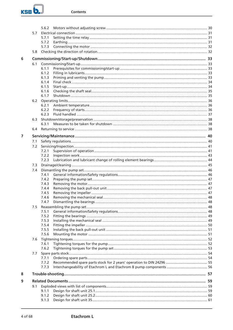
Fig. 5: Etachrom L name plate (example)
1 Type series, size and version 2 Material number (optional)
3 KSB order No., order item No. andconsecutive No.
4 Flow rate
5 Kinematic viscosity of the fluidhandled
6 Minimum efficiency index
7 Impeller diameter 8 Head
9 Speed 10 Year of construction
11 Efficiency (see data sheet)
4.5 Design details
Design
▪ Design with materials to Regulation (EC) No. 1935/2004 can be provided.
▪ Design to ATEX
Design
▪ Annular casing pumps
▪ Back pull-out design
▪ Flanges to EN 1092-1

4 Description of the Pump (Set)
19 of 68Etachrom L
▪ Horizontal installation
▪ Single-stage
▪ Dimensions and ratings to EN 733
▪ Pump and motor connected by shaft coupling
Pump casing
▪ Annular casing with welded-on or bolted-on pump feet
▪ Replaceable casing wear rings
Drive
Standard design:
▪ KSB surface-cooled IEC three-phase current squirrel-cage motor
▪ 50 Hz winding, 220 - 240 V / 380 - 420 V ≤ 2.20 kW
▪ 50 Hz winding, 380 - 420 V / 660 - 725 V ≥ 3.00 kW
▪ 60 Hz winding, 440 - 480 V ≤ 2.60 kW
▪ 60 Hz winding, 440 - 480 V ≥ 3.60 kW
▪ Type of construction B3
▪ Duty cycle: continuous duty S1
▪ Enclosure IP55
▪ Thermal class F
▪ 3 PTC thermistors
or
▪ KSB surface-cooled IEC frame three-phase current squirrel-cage motor asdescribed above, but West European make to our choice
or
Explosion-proof version:
▪ Surface-cooled IEC three-phase current squirrel-cage motor
▪ 50 Hz winding, 220 - 240 V / 380 - 420 V ≤ 1.85 kW
▪ 50 Hz winding, 380 - 420 V / 660 - 725 V ≥ 2.50 kW
▪ Enclosure IP55 or IP54
▪ Type of protection EEx e II
▪ Temperature class T3
Shaft seal
▪ Single mechanical seal to EN 12756
▪ The shaft is fitted with a replaceable shaft sleeve in the shaft seal area (sizes080-065-250, 100-080-200, 100-080-250)
Impeller type
▪ Closed radial impeller with multiply curved vanes
Bearings
▪ Grease-packed radial ball bearing
Automation
Automation options:
▪ PumpDrive
▪ PumpMeter
4 Description of the Pump (Set)
20 of 68 Etachrom L
4.6 Configuration and function
1 2 543
6 7 1098
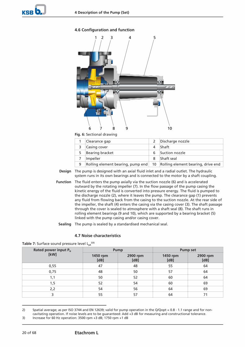
Fig. 6: Sectional drawing
1 Clearance gap 2 Discharge nozzle
3 Casing cover 4 Shaft
5 Bearing bracket 6 Suction nozzle
7 Impeller 8 Shaft seal
9 Rolling element bearing, pump end 10 Rolling element bearing, drive end
Design The pump is designed with an axial fluid inlet and a radial outlet. The hydraulicsystem runs in its own bearings and is connected to the motor by a shaft coupling.
Function The fluid enters the pump axially via the suction nozzle (6) and is acceleratedoutward by the rotating impeller (7). In the flow passage of the pump casing thekinetic energy of the fluid is converted into pressure energy. The fluid is pumped tothe discharge nozzle (2), where it leaves the pump. The clearance gap (1) preventsany fluid from flowing back from the casing to the suction nozzle. At the rear side ofthe impeller, the shaft (4) enters the casing via the casing cover (3). The shaft passagethrough the cover is sealed to atmosphere with a shaft seal (8). The shaft runs inrolling element bearings (9 and 10), which are supported by a bearing bracket (5)linked with the pump casing and/or casing cover.
Sealing The pump is sealed by a standardised mechanical seal.
4.7 Noise characteristics
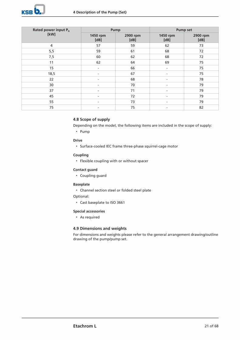
Table 7: Surface sound pressure level LpA2)3)
Rated power input PN
[kW]Pump Pump set
1450 rpm [dB]
2900 rpm[dB]
1450 rpm[dB]
2900 rpm[dB]
0,55 47 48 55 64
0,75 48 50 57 64
1,1 50 52 60 64
1,5 52 54 60 69
2,2 54 56 64 69
3 55 57 64 71
2) Spatial average; as per ISO 3744 and EN 12639; valid for pump operation in the Q/Qopt = 0.8 - 1.1 range and for non-cavitating operation. If noise levels are to be guaranteed: Add +3 dB for measuring and constructional tolerance.
3) Increase for 60 Hz operation: 3500 rpm +3 dB; 1750 rpm +1 dB
4 Description of the Pump (Set)
21 of 68Etachrom L
Rated power input PN
[kW]Pump Pump set
1450 rpm [dB]
2900 rpm[dB]
1450 rpm[dB]
2900 rpm[dB]
4 57 59 62 73
5,5 59 61 68 72
7,5 60 62 68 72
11 62 64 69 75
15 - 66 - 75
18,5 - 67 - 75
22 - 68 - 78
30 - 70 - 79
37 - 71 - 79
45 - 72 - 79
55 - 73 - 79
75 - 75 - 82
4.8 Scope of supplyDepending on the model, the following items are included in the scope of supply:
▪ Pump
Drive
▪ Surface-cooled IEC frame three-phase squirrel-cage motor
Coupling
▪ Flexible coupling with or without spacer
Contact guard
▪ Coupling guard
Baseplate
▪ Channel section steel or folded steel plate
Optional:
▪ Cast baseplate to ISO 3661
Special accessories
▪ As required
4.9 Dimensions and weightsFor dimensions and weights please refer to the general arrangement drawing/outlinedrawing of the pump/pump set.
5 Installation at Site
22 of 68 Etachrom L
5 Installation at Site
5.1 Checks to be carried out prior to installation
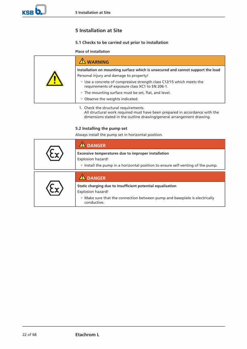
Place of installation
WARNING
Installation on mounting surface which is unsecured and cannot support the load
Personal injury and damage to property!
▷ Use a concrete of compressive strength class C12/15 which meets therequirements of exposure class XC1 to EN 206-1.
▷ The mounting surface must be set, flat, and level.
▷ Observe the weights indicated.
1. Check the structural requirements.All structural work required must have been prepared in accordance with thedimensions stated in the outline drawing/general arrangement drawing.
5.2 Installing the pump setAlways install the pump set in horizontal position.
DANGER
Excessive temperatures due to improper installation
Explosion hazard!
▷ Install the pump in a horizontal position to ensure self-venting of the pump.
DANGER
Static charging due to insufficient potential equalisation
Explosion hazard!
▷ Make sure that the connection between pump and baseplate is electricallyconductive.

5 Installation at Site
23 of 68Etachrom L
5.2.1 Installation on the foundation
L1
32Fig. 7: Fitting the shims
L Bolt-to-bolt distance 1 Shim
2 Shim if (L) > 800 mm 3 Foundation bolt
ü The foundation has the required strength and characteristics.
ü The foundation has been prepared in accordance with the dimensions given inthe outline drawing/general arrangement drawing.
1. Position the pump set on the foundation and level it with the help of a spiritlevel placed on the shaft and discharge nozzle.Permissible deviation: 0.2 mm/m
2. Use shims (1) for height compensation, if necessary. Always fit shims, if any, immediately to the left and right of the foundationbolts (3) between the baseplate/foundation frame and the foundation.For a bolt-to-bolt distance (L) > 800 mm fit additional shims (2) halfway betweenthe bolt holes. All shims must lie perfectly flush.
3. Insert the foundation bolts (3) into the holes provided.
4. Use concrete to set the foundation bolts (3) into the foundation.
5. Wait until the concrete has set firmly, then level the baseplate.
6. Tighten the foundation bolts (3) evenly and firmly.
NOTE
For baseplates more than 400 mm wide grouting the baseplate with low-shrinkageconcrete is recommended.
NOTE
For baseplates made of grey cast iron grouting the baseplate with low-shrinkageconcrete is recommended.
NOTE
For low-noise operation contact the manufacturer to check whether the pump setcan be installed on anti-vibration mounts.
NOTE
Expansion joints can be fitted between the pump and the suction/discharge line.
5 Installation at Site
24 of 68 Etachrom L
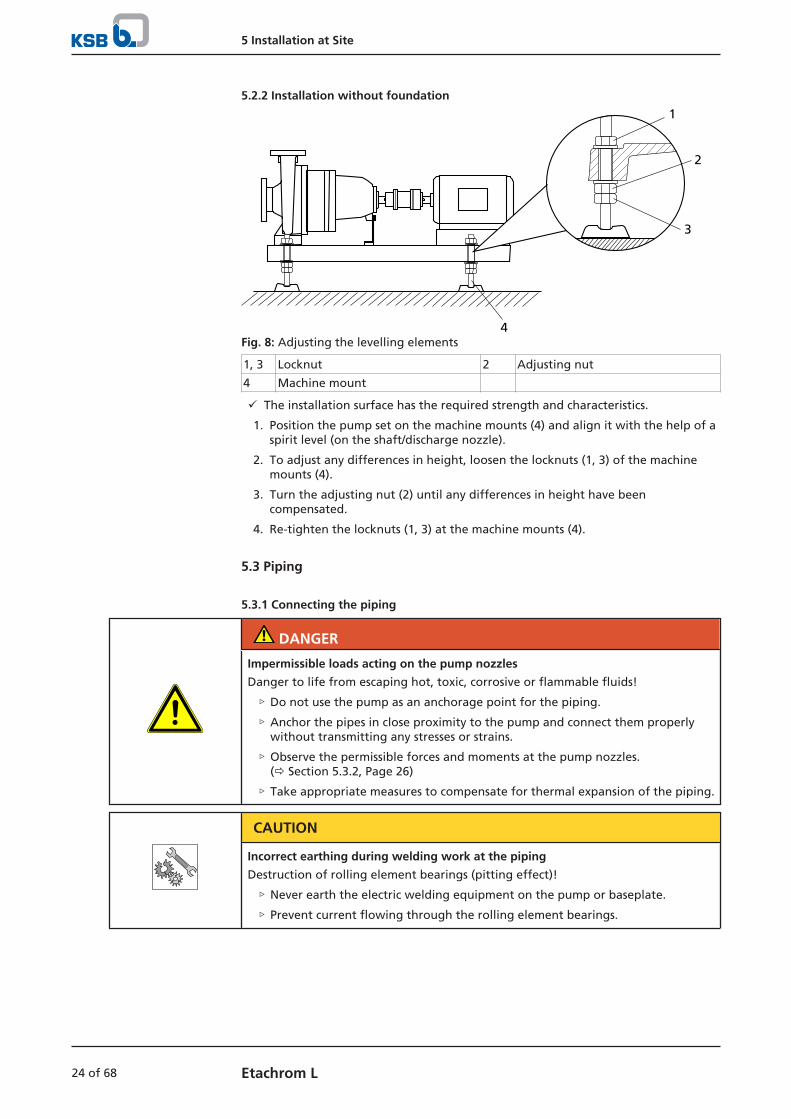
5.2.2 Installation without foundation
4
1
2
3
Fig. 8: Adjusting the levelling elements
1, 3 Locknut 2 Adjusting nut
4 Machine mount
ü The installation surface has the required strength and characteristics.
1. Position the pump set on the machine mounts (4) and align it with the help of aspirit level (on the shaft/discharge nozzle).
2. To adjust any differences in height, loosen the locknuts (1, 3) of the machinemounts (4).
3. Turn the adjusting nut (2) until any differences in height have beencompensated.
4. Re-tighten the locknuts (1, 3) at the machine mounts (4).
5.3 Piping
5.3.1 Connecting the piping
DANGER
Impermissible loads acting on the pump nozzles
Danger to life from escaping hot, toxic, corrosive or flammable fluids!
▷ Do not use the pump as an anchorage point for the piping.
▷ Anchor the pipes in close proximity to the pump and connect them properlywithout transmitting any stresses or strains.
▷ Observe the permissible forces and moments at the pump nozzles.(ð Section 5.3.2, Page 26)
▷ Take appropriate measures to compensate for thermal expansion of the piping.
CAUTION
Incorrect earthing during welding work at the piping
Destruction of rolling element bearings (pitting effect)!
▷ Never earth the electric welding equipment on the pump or baseplate.
▷ Prevent current flowing through the rolling element bearings.

5 Installation at Site
25 of 68Etachrom L
NOTE
Installing check and shut-off elements in the system is recommended, depending onthe type of plant and pump. However, such elements must not obstruct properdrainage or hinder disassembly of the pump.
ü Suction lift lines have been laid with a rising slope, suction head lines with adownward slope towards the pump.
ü A flow stabilisation section having a length equivalent to at least twice thediameter of the suction flange has been provided upstream of the suction flange.
ü The nominal diameters of the pipelines are equal to or greater than the nominaldiameters of the pump nozzles.
ü Adapters to larger nominal diameters are designed with a diffuser angle ofapprox. 8° to avoid excessive pressure losses.
ü The pipelines have been anchored in close proximity to the pump and connectedwithout transmitting any stresses or strains.
CAUTION
Welding beads, scale and other impurities in the piping
Damage to the pump!
▷ Remove any impurities from the piping.
▷ If necessary, install a filter.
▷ Observe the information in (ð Section 7.2.2.3, Page 44) .
1. Thoroughly clean, flush and blow through all vessels, pipelines and connections(especially of new installations).
2. Before installing the pump in the piping, remove the flange covers on thesuction and discharge nozzles of the pump.
3. Check that the inside of the pump is free from any foreign objects. Remove anyforeign objects.
4. If required, install a filter in the piping (see drawing: Filter in the piping).
1
2Fig. 9: Filter in the piping
1 Differential pressure gauge 2 Filter
NOTE
Use a filter with laid-in wire mesh (mesh width 0.5 mm, wire diameter 0.25 mm) ofcorrosion-resistant material.Use a filter with a filter area three times the cross-section of the piping.Conical filters have proved suitable.
5. Connect the pump nozzles to the piping.

5 Installation at Site
26 of 68 Etachrom L
CAUTION
Aggressive flushing liquid and pickling agent
Damage to the pump!
▷ Match the cleaning operation mode and duration of flushing and pickling tothe casing materials and seal materials used.
5.3.2 Permissible forces and moments at the pump nozzles
FV
FVmax
2FH
FHmax
2
Mtmax
Mt
2
+ + - 1
FV
FH
FH
FVFH
FH
Fig. 10: Forces and moments at the pump nozzles
The following condition must be met:
∑IFVI, ∑IFHI, and ∑IMtI are the sums of the absolute values of the respective loadsacting on the nozzles. Neither the load direction nor the load distribution among thenozzles are taken into account in these sums.
Table 8: Forces and moments at the pump nozzles4)
Size FVmax FHmax Mtmax
[kN] [kN] [kNm]
050-025-125.1 2,6 1,8 0,55
050-025-125 2,6 1,8 0,55
050-025-160 2,5 1,7 0,5
050-025-200 2,5 1,7 0,5
050-025-250 2,5 1,7 0,5
050-032-125.1 2,6 1,8 0,55
050-032-125 2,6 1,8 0,55
050-032-160 2,5 1,7 0,5
050-032-200 2,5 1,7 0,5
050-032-250 2,5 1,7 0,5
065-040-125 2,6 1,8 0,6
065-040-160 2,6 1,8 0,6
065-040-200 2,6 1,8 0,6
065-040-250 2,6 1,8 0,6
065-050-125 2,7 2,0 0,75
065-050-160 2,7 1,9 0,7
065-050-200 2,7 1,9 0,7
065-050-250 2,7 1,9 0,7
080-065-200 3,0 2,2 0,85
080-065-250 3,2 2,4 1,05
100-080-200 4,0 2,9 1,45
100-080-250 4,0 2,9 1,45
4) The indicated values apply to pumps made of chrome nickel molybdenum steel 1.4571 on non-grouted baseplates.

5 Installation at Site
27 of 68Etachrom L
5.3.3 Vacuum balance line
NOTE
Where fluid has to be pumped out of a vessel under vacuum, installing a vacuumbalance line is recommended.
The following rules apply to vacuum balance lines:
▪ Minimum nominal line diameter 25 mm.
▪ The line extends above the highest permissible fluid level in the vessel.
1 2
5
43
6Fig. 11: Vacuum balance system
1 Vessel under vacuum 2 Vacuum balance line
3 Shut-off element 4 Swing check valve
5 Main shut-off element 6 Vacuum-tight shut-off element
NOTE
An additional line fitted with a shut-off valve (from the pump discharge nozzle tothe balance line) facilitates venting of the pump before start-up.
5.4 Enclosure/insulation
DANGER
Risk of potentially explosive atmosphere due to insufficient venting
Explosion hazard!
▷ Make sure the space between the casing cover/discharge cover and the bearingcover is sufficiently vented.
▷ Never close or cover the perforation of the bearing bracket guards (e.g. byinsulation).
WARNING
The volute casing and casing/discharge cover take on the same temperature as thefluid handled
Risk of burns!
▷ Insulate the volute casing.
▷ Fit protective equipment.
5 Installation at Site
28 of 68 Etachrom L
CAUTION
Heat build-up in the bearing bracket
Damage to the bearing!
▷ Never insulate the bearing bracket, bearing bracket lantern and casing cover.
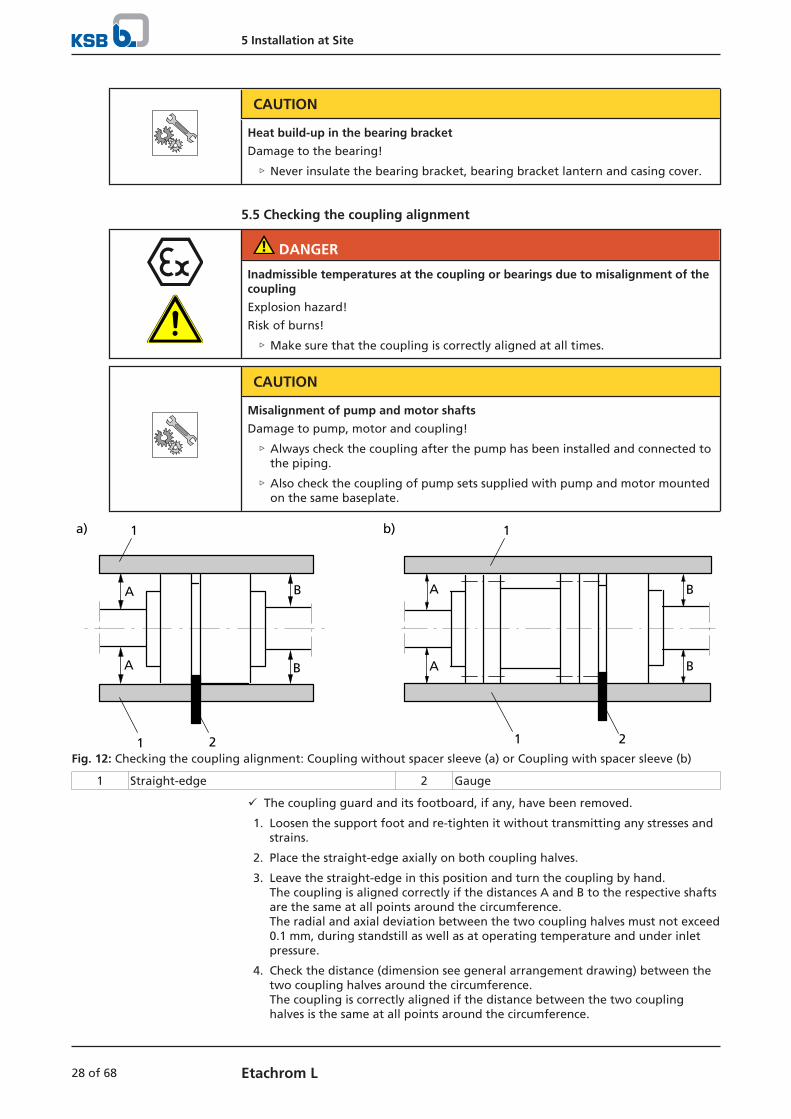
5.5 Checking the coupling alignment
DANGER
Inadmissible temperatures at the coupling or bearings due to misalignment of thecoupling
Explosion hazard!
Risk of burns!
▷ Make sure that the coupling is correctly aligned at all times.
CAUTION
Misalignment of pump and motor shafts
Damage to pump, motor and coupling!
▷ Always check the coupling after the pump has been installed and connected tothe piping.
▷ Also check the coupling of pump sets supplied with pump and motor mountedon the same baseplate.
BA
A B
a) b)
B
B
A
A
1
1 2 21
1
Fig. 12: Checking the coupling alignment: Coupling without spacer sleeve (a) or Coupling with spacer sleeve (b)
1 Straight-edge 2 Gauge
ü The coupling guard and its footboard, if any, have been removed.
1. Loosen the support foot and re-tighten it without transmitting any stresses andstrains.
2. Place the straight-edge axially on both coupling halves.
3. Leave the straight-edge in this position and turn the coupling by hand. The coupling is aligned correctly if the distances A and B to the respective shaftsare the same at all points around the circumference.The radial and axial deviation between the two coupling halves must not exceed0.1 mm, during standstill as well as at operating temperature and under inletpressure.
4. Check the distance (dimension see general arrangement drawing) between thetwo coupling halves around the circumference. The coupling is correctly aligned if the distance between the two couplinghalves is the same at all points around the circumference.

5 Installation at Site
29 of 68Etachrom L
The radial and axial deviation between the two coupling halves must not exceed0.1 mm, during standstill as well as at operating temperature and under inletpressure.
5. If alignment is correct, re-install the coupling guard and its footboard, if any.
Checking the coupling alignment with a laser tool
Coupling alignment may also be checked with a laser tool. Observe thedocumentation provided by the manufacturer of the measuring instrument.
5.6 Aligning the pump and motorAfter having installed the pump set and connected the piping, check the couplingalignment and, if required, re-align the pump set (at the motor).
5.6.1 Motors with adjusting screw
1
3
2
Fig. 13: Motor with adjusting screw
1 Hexagon head bolt 2 Adjusting screw
3 Locknut
ü The coupling guard and its footboard, if any, have been removed.
1. Check the coupling alignment.
2. Unscrew the hexagon head bolts (1) at the motor and the locknuts (3) at thebaseplate.
3. Turn the adjusting screws (2) by hand or by means of an open-end wrench untilthe coupling alignment is correct and all motor feet rest squarely on thebaseplate.
4. Re-tighten the hexagon head bolts (1) at the motor and the locknuts (3) at thebaseplate.
5. Check proper functioning of coupling/shaft. Check that coupling/shaft can easily be rotated by hand.
WARNING
Unprotected rotating coupling
Risk of injury by rotating shafts!
▷ Always operate the pump set with a coupling guard.If the customer specifically requests not to include a coupling guard in KSB'sdelivery, then the operator must supply one!
▷ Observe all relevant regulations for selecting a coupling guard.

5 Installation at Site
30 of 68 Etachrom L
DANGER
Risk of ignition by frictional sparks
Explosion hazard!!
▷ Choose a coupling guard material that is non-sparking in the event ofmechanical contact.
6. Fit the coupling guard and its footboard, if any.
7. Check the distance between coupling and coupling guard.The coupling guard must not touch the coupling.
5.6.2 Motors without adjusting screw
Any differences in the centreline heights of the pump and motor shafts arecompensated by means of shims.
1Fig. 14: Pump set with shim
1 Shim
ü The coupling guard and its footboard, if any, have been removed.
1. Check the coupling alignment.
2. Loosen the hexagon head bolts at the motor.
3. Insert shims underneath the motor feet until the difference in shaft centrelineheight has been compensated.
4. Re-tighten the hexagon head bolts.
5. Check proper functioning of coupling/shaft. Check that coupling/shaft can easily be rotated by hand.
WARNING
Unprotected rotating coupling
Risk of injury by rotating shafts!
▷ Always operate the pump set with a coupling guard.If the customer specifically requests not to include a coupling guard in KSB'sdelivery, then the operator must supply one!
▷ Observe all relevant regulations for selecting a coupling guard.
DANGER
Risk of ignition by frictional sparks
Explosion hazard!!
▷ Choose a coupling guard material that is non-sparking in the event ofmechanical contact.
6. Fit the coupling guard and its footboard, if any.
7. Check the distance between coupling and coupling guard.The coupling guard must not touch the coupling.
5 Installation at Site
31 of 68Etachrom L
5.7 Electrical connection
DANGER
Electrical connection work by unqualified personnel
Risk of fatal injury due to electric shock!
▷ Always have the electrical connections installed by a trained and qualifiedelectrician.
▷ Observe regulations IEC 60364 and, for explosion-proof models, EN 60079.
WARNING
Incorrect connection to the mains
Damage to the mains network, short circuit!
▷ Observe the technical specifications of the local energy supply companies.
1. Check the available mains voltage against the data on the motor name plate.
2. Select an appropriate starting method.
NOTE
A motor protection device is recommended.
5.7.1 Setting the time relay
CAUTION
Switchover between star and delta on three-phase motors with star-delta startingtakes too long.
Damage to the pump (set)!
▷ Keep switch-over intervals between star and delta as short as possible.
Table 9: Time relay settings for star-delta starting:
Motor rating Y time to be set
[kW] [s]
≤ 30 < 3
> 30 < 5
5.7.2 Earthing
DANGER
Electrostatic charging
Explosion hazard!
Damage to the pump set!
▷ Connect the PE conductor to the earthing terminal provided.
▷ Provide for potential equalisation between the pump set and foundation.

5 Installation at Site
32 of 68 Etachrom L
5.7.3 Connecting the motor
NOTE
In compliance with IEC 60034-8, three-phase motors are always wired for clockwiserotation (looking at the motor shaft stub).
The pump's direction of rotation is indicated by an arrow on the pump.
1. Match the motor's direction of rotation to that of the pump.
2. Observe the manufacturer's product literature supplied with the motor.
5.8 Checking the direction of rotation
DANGER
Temperature increase resulting from contact between rotating and stationarycomponents
Explosion hazard!
Damage to the pump set!
▷ Never check the direction of rotation by starting up the unfilled pump set.
▷ Separate the pump from the motor to check the direction of rotation.
WARNING
Hands inside the pump casing
Risk of injuries, damage to the pump!
▷ Always disconnect the pump set from the power supply and secure it againstunintentional start-up before inserting your hands or other objects into thepump.
CAUTION
Incorrect direction of rotation with non-reversible mechanical seal
Damage to the mechanical seal and leakage!
▷ Separate the pump from the motor to check the direction of rotation.
CAUTION
Drive and pump running in the wrong direction of rotation
Damage to the pump!
▷ Refer to the arrow indicating the direction of rotation on the pump.
▷ Check the direction of rotation. If required, check the electrical connection andcorrect the direction of rotation.
The correct direction of rotation of the motor and pump is clockwise (seen from thedrive end).
1. Start the motor and stop it again immediately to determine the motor'sdirection of rotation.
2. Check the direction of rotation. The motor's direction of rotation must match the arrow indicating the directionof rotation on the pump.
3. If the motor is running in the wrong direction of rotation, check the electricalconnection of the motor and switchgear, if any.

6 Commissioning/Start-up/Shutdown
33 of 68Etachrom L
6 Commissioning/Start-up/Shutdown
6.1 Commissioning/Start-up
6.1.1 Prerequisites for commissioning/start-up
Before commissioning/starting up the pump set, make sure that the followingconditions are met:
▪ The pump set has been mechanically connected as specified.
▪ The pump set has been properly connected to the power supply and is equippedwith all protection devices. (ð Section 5.7, Page 31)
▪ The pump has been primed with the fluid to be handled. The pump has beenvented.
▪ The direction of rotation has been checked. (ð Section 5.8, Page 32)
▪ All auxiliary connections required are connected and operational.
▪ The lubricants have been checked. (ð Section 6.1.2, Page 33)
▪ After prolonged shutdown of the pump (set), the activities required for returningthe equipment to service have been carried out. (ð Section 6.4, Page 38)
6.1.2 Filling in lubricants
Grease-lubricated bearings have been packed with grease at the factory.
6.1.3 Priming and venting the pump
DANGER
Risk of potentially explosive atmosphere inside the pump
Explosion hazard!
▷ The pump internals in contact with the fluid to be handled, including the sealchamber and auxiliary systems must be filled with the fluid to be handled at alltimes.
▷ Provide sufficient inlet pressure.
▷ Provide an appropriate monitoring system.
CAUTION
Increased wear due to dry running
Damage to the pump set!
▷ Never operate the pump set without liquid fill.
▷ Never close the shut-off element in the suction line and/or supply line duringpump operation.
1. Vent the pump and suction line and prime both with the fluid to be handled.
2. Fully open the shut-off element in the suction line.
3. Fully open all auxiliary feed lines (barrier fluid, flushing liquid, etc.), if any.
4. Open the shut-off element, if any, in the vacuum balance line and close thevacuum-tight shut-off element, if any. (ð Section 5.3.3, Page 27)
NOTE
For design-inherent reasons some unfilled volume in the hydraulic system cannot beexcluded after the pump has been primed for commissioning/start-up. However,once the motor is started up the pumping effect will immediately fill this volumewith the fluid handled.

6 Commissioning/Start-up/Shutdown
34 of 68 Etachrom L
6.1.4 Final check
1. Remove the coupling guard and its footboard, if any.
2. Check the coupling alignment; re-align the coupling, if required.(ð Section 5.5, Page 28)
3. Check proper functioning of coupling/shaft.Check that coupling/shaft can be easily rotated by hand.
4. Fit the coupling guard and its footboard, if any.
5. Check the distance between coupling and coupling guard.The coupling guard must not touch the coupling.
6.1.5 Start-up
DANGER
Non-compliance with the permissible pressure and temperature limits if the pumpis operated with the suction and/or discharge line closed.
Explosion hazard!
Hot or toxic fluids escaping!
▷ Never operate the pump with the shut-off elements in the suction line and/ordischarge line closed.
▷ Only start up the pump set with the discharge-side shut-off element slightly orfully open.
DANGER
Excessive temperatures due to dry running or excessive gas content in the fluidhandled
Explosion hazard!
Damage to the pump set!
▷ Never operate the pump set without liquid fill.
▷ Prime the pump as per operating instructions.
▷ Always operate the pump within the permissible operating range.
CAUTION
Abnormal noises, vibrations, temperatures or leakage
Damage to the pump!
▷ Switch off the pump (set) immediately.
▷ Eliminate the causes before returning the pump set to service.
ü The system piping has been cleaned.
ü The pump, suction line and inlet tank, if any, have been vented and primed withthe fluid to be pumped.
ü The lines for priming and venting have been closed.

6 Commissioning/Start-up/Shutdown
35 of 68Etachrom L
CAUTION
Start-up against open discharge line
Motor overload!
▷ Make sure the motor has sufficient power reserves.
▷ Use a soft starter.
▷ Use speed control.
1. Fully open the shut-off element in the suction head/suction lift line.
2. Close or slightly open the shut-off element in the discharge line.
3. Start up the motor.
4. Immediately after the pump has reached full rotational speed, slowly open theshut-off element in the discharge line and adjust it to comply with the dutypoint.
CAUTION
Misalignment of pump and coupling
Damage to pump, motor and coupling!
▷ When the operating temperature has been reached, switch off the pump setand check the coupling alignment.
5. Check the coupling alignment and re-align the coupling, if required.
6.1.6 Checking the shaft seal
Mechanical seal The mechanical seal only leaks slightly or invisibly (as vapour) during operation.Mechanical seals are maintenance-free.
6.1.7 Shutdown
CAUTION
Heat build-up inside the pump
Damage to the shaft seal!
▷ Depending on the type of installation, the pump set requires sufficient after-run time – with the heat source switched off – until the fluid handled hascooled down.
ü The shut-off valve in the suction line is and remains open.
1. Close the shut-off valve in the discharge line.
2. Switch off the motor and make sure the pump set runs down smoothly to astandstill.
NOTE
If the discharge line is equipped with a non-return or check valve, the shut-offelement may remain open provided that the system conditions and systemregulations are considered and observed.
For prolonged shutdown periods:
1. Close the shut-off valve in the suction line.
2. Close the auxiliary connections.

6 Commissioning/Start-up/Shutdown
36 of 68 Etachrom L
CAUTION
Risk of freezing during prolonged pump shutdown periods
Damage to the pump!
▷ Drain the pump and the cooling/heating chambers (if any) or otherwise protectthem against freezing.
6.2 Operating limits
DANGER
Non-compliance with operating limits for pressure, temperature, fluid handled andspeed
Explosion hazard!
Hot or toxic fluid could escape!
▷ Comply with the operating data indicated in the data sheet.
▷ Never use the pump for handling fluids it is not designed for.
▷ Avoid prolonged operation against a closed shut-off element.
▷ Never operate the pump at temperatures, pressures or rotational speedsexceeding those specified in the data sheet or on the name plate unless thewritten consent of the manufacturer has been obtained.
DANGER
Formation of a potentially explosive atmosphere inside the pump
Explosion hazard!
▷ When draining tanks take suitable measures to prevent dry running of thepump (e.g. fill level monitoring).
6.2.1 Ambient temperature
CAUTION
Operation outside the permissible ambient temperature
Damage to the pump (set)!
▷ Observe the specified limits for permissible ambient temperatures.
Observe the following parameters and values during operation:
Table 10: Permissible ambient temperatures
Permissible ambient temperature Value
Maximum 40 °C
Minimum See data sheet.
6.2.2 Frequency of starts
DANGER
Excessive surface temperature of the motor
Explosion hazard!
Damage to the motor!
▷ In case of explosion-proof motors, observe the frequency of starts specified inthe manufacturer's product literature.

6 Commissioning/Start-up/Shutdown
37 of 68Etachrom L
The frequency of starts is usually determined by the maximum temperature increaseof the motor. This largely depends on the power reserves of the motor in steady-state operation and on the starting conditions (DOL, star-delta, moments of inertia,etc). If the starts are evenly spaced over the period indicated, the pump set can bestarted up six times per hour (h) with the discharge-side gate valve slightly open.
CAUTION
Re-starting while motor is still running down
Damage to the pump (set)!
▷ Do not re-start the pump set before the pump rotor has come to a standstill.
6.2.3 Fluid handled
6.2.3.1 Flow rate
Table 11: Flow rate
Temperature range (t) Minimum flow rate Maximum flow rate
-30 to +70 ℃ ≈ 15 % of QOpt5) See hydraulic curves
> 70 to +110 °C ≈ 25 % of QOpt5)
The calculation formula below can be used to check if an additional heat build-upcould lead to a dangerous temperature increase at the pump surface.
××
×
Table 12: Key
Symbol Description Unit
c Specific heat capacity J/kg K
g Gravitational constant m/s²
H Pump discharge head m
Tf Fluid temperature °C
TO Temperature at the casing surface °C
Pump efficiency at duty point -
Temperature difference K
6.2.3.2 Density of the fluid handled
The pump input power changes in proportion to the density of the fluid handled.
CAUTION
Impermissibly high density of the fluid handled
Motor overload!
▷ Observe the information about fluid density in the data sheet.
▷ Make sure the motor has sufficient power reserves.
5) Best efficiency point

6 Commissioning/Start-up/Shutdown
38 of 68 Etachrom L
6.2.3.3 Abrasive fluids
The fluid handled may contain abrasive particles up to a maximum content of 5 g/dm³ and a maximum particle size of 0.5 mm. When the pump handles fluidscontaining abrasive substances, increased wear of the hydraulic system and the shaftseal are to be expected. In this case, reduce the commonly recommended inspectionintervals.
DANGER
Abraded casing wall
Explosion hazard!
▷ Use a pump with anti-swirl baffle.
▷ Adjust the inspection intervals to the increased abrasion.
▷ For combustible fluids: The fluids must not contain any abrasive particles.
6.3 Shutdown/storage/preservation
6.3.1 Measures to be taken for shutdown
The pump (set) remains installed
ü Sufficient fluid is supplied for the functional check run of the pump.
1. For prolonged shutdown periods, start up the pump (set) regularly betweenonce a month and once every three months for approximately five minutes.
ð This will prevent the formation of deposits within the pump and the pumpintake area.
The pump (set) is removed from the pipe and stored
ü The pump has been properly drained. (ð Section 7.3, Page 45)
ü The safety instructions for dismantling the pump have been observed.(ð Section 7.4.1, Page 46)
1. Spray-coat the inside wall of the pump casing and, in particular, the impellerclearance areas with a preservative.
2. Spray the preservative through the suction nozzle and discharge nozzle.It is advisable to then close the pump nozzles (e.g. with plastic caps).
3. Oil or grease all exposed machined parts and surfaces of the pump (withsilicone-free oil or grease, food-approved if required) to protect them againstcorrosion.Observe the additional instructions on preservation. (ð Section 3.3, Page 14)
If the pump set is to be stored temporarily, do not preserve the wetted componentsmade of alloy materials.
Observe any additional instructions and information provided. (ð Section 3, Page 13)
6.4 Returning to serviceFor returning the equipment to service observe the sections on commissioning/start-up and the operating limits. (ð Section 6.1, Page 33) (ð Section 6.2, Page 36)
In addition, carry out all servicing/maintenance operations before returning thepump (set) to service. (ð Section 7, Page 40)
WARNING
Failure to re-install or re-activate protective devices
Risk of injury from moving parts or escaping fluid!
▷ As soon as the work is completed, re-install and re-activate any safety-relevantdevices and protective devices.

6 Commissioning/Start-up/Shutdown
39 of 68Etachrom L
NOTE
If the pump has been out of service for more than one year, replace all elastomerseals.

7 Servicing/Maintenance
40 of 68 Etachrom L
7 Servicing/Maintenance
7.1 Safety regulations
DANGER
Improper cleaning of coated pump surfaces
Explosion hazard by electrostatic discharge!
▷ When cleaning coated pump surfaces in atmospheres of Explosion group IIC,use suitable anti-static equipment.
DANGER
Sparks produced during servicing work
Explosion hazard!
▷ Observe the safety regulations in force at the place of installation!
▷ Always perform maintenance work at an explosion-proof pump (set) outside ofpotentially explosive atmospheres.
DANGER
Improperly serviced pump set
Explosion hazard!
Damage to the pump set!
▷ Service the pump set regularly.
▷ Prepare a maintenance schedule with special emphasis on lubricants, shaft sealand coupling.
The operator ensures that maintenance, inspection and installation is performed byauthorised, qualified specialist personnel who are thoroughly familiar with themanual.
WARNING
Unintentional starting of the pump set
Risk of injury by moving components and shock currents!
▷ Ensure that the pump set cannot be started unintentionally.
▷ Always make sure the electrical connections are disconnected before carryingout work on the pump set.
WARNING
Fluids handled, consumables and supplies which are hot and/or pose a healthhazard
Risk of injury!
▷ Observe all relevant laws.
▷ When draining the fluid take appropriate measures to protect persons and theenvironment.
▷ Decontaminate pumps which handle fluids posing a health hazard.

7 Servicing/Maintenance
41 of 68Etachrom L
WARNING
Insufficient stability
Risk of crushing hands and feet!
▷ During assembly/dismantling, secure the pump (set)/pump parts to preventtilting or tipping over.
A regular maintenance schedule will help avoid expensive repairs and contribute totrouble-free, reliable operation of the pump, pump set and pump parts with aminimum of servicing/maintenance expenditure and work.
NOTE
All maintenance work, service work and installation work can be carried out by KSBService or authorised workshops. For contact details please refer to the enclosed"Addresses" booklet or visit "www.ksb.com/contact" on the Internet.
Never use force when dismantling and reassembling the pump set.
7.2 Servicing/Inspection
7.2.1 Supervision of operation
DANGER
Risk of potentially explosive atmosphere inside the pump
Explosion hazard!
▷ The pump internals in contact with the fluid to be handled, including the sealchamber and auxiliary systems must be filled with the fluid to be handled at alltimes.
▷ Provide sufficient inlet pressure.
▷ Provide an appropriate monitoring system.
DANGER
Incorrectly serviced shaft seal
Explosion hazard!
Hot, toxic fluid escaping!
Damage to the pump set!
Risk of burns!
Fire hazard!
▷ Regularly service the shaft seal.
DANGER
Excessive temperatures as a result of bearings running hot or defective bearingseals
Explosion hazard!
Fire hazard!
Damage to the pump set!
▷ Regularly check the rolling element bearings for running noises.

7 Servicing/Maintenance
42 of 68 Etachrom L
DANGER
Incorrectly serviced barrier fluid system
Explosion hazard!
Fire hazard!
Damage to the pump set!
Hot and/or toxic fluids escaping!
▷ Regularly service the barrier fluid system.
▷ Monitor the barrier fluid pressure.
CAUTION
Increased wear due to dry running
Damage to the pump set!
▷ Never operate the pump set without liquid fill.
▷ Never close the shut-off element in the suction line and/or supply line duringpump operation.
CAUTION
Impermissibly high temperature of fluid handled
Damage to the pump!
▷ Prolonged operation against a closed shut-off element is not permitted(heating up of the fluid).
▷ Observe the temperature limits in the data sheet and in the section onoperating limits. (ð Section 6.2, Page 36)
While the pump is in operation, observe and check the following:
▪ The pump must run quietly and free from vibrations at all times.
▪ Check the shaft seal. (ð Section 6.1.6, Page 35)
▪ Check the sealing elements for leakage.
▪ Check the rolling element bearings for running noises.Vibrations, noise and an increase in current input occurring during unchangedoperating conditions indicate wear.
▪ Monitor the correct functioning of any auxiliary connections.
▪ Monitor the stand-by pump.To make sure that the stand-by pumps are ready for operation, start them uponce a week.
▪ Monitor the bearing temperature.The bearing temperature must not exceed 90 °C (measured at the motorhousing).
CAUTION
Operation outside the permissible bearing temperature
Damage to the pump!
▷ The bearing temperature of the pump (set) must never exceed 90 °C (measuredon the outside of the motor housing).

7 Servicing/Maintenance
43 of 68Etachrom L
NOTE
After commissioning, increased temperatures may occur at grease-lubricated rollingelement bearings due to the running-in process. The final bearing temperature isonly reached after a certain period of operation (up to 48 hours depending on theconditions).
7.2.2 Inspection work
DANGER
Excessive temperatures caused by friction, impact or frictional sparks
Explosion hazard!
Fire hazard!
Damage to the pump set!
▷ Regularly check the coupling guard, plastic components and other guards ofrotating parts for deformation and sufficient distance from rotating parts.
DANGER
Static charging due to insufficient potential equalisation
Explosion hazard!
▷ Make sure that the connection between pump and baseplate is electricallyconductive.
7.2.2.1 Checking the coupling
Check the flexible elements of the coupling. Replace the relevant parts in due time ifthere is any sign of wear and check the alignment.
7.2.2.2 Checking the clearances
For checking the clearances remove the impeller, if required.(ð Section 7.4.5, Page 47) If the clearance is larger than permitted, fit a new casing wear ring 502.01 and/or502.02 and/or 502.06 (WS35).The clearances given refer to the diameter.
Table 13: Clearances between impeller and casing [mm]
Size Suction side Pressure side Nominal impeller diameter [mm]
125 160 200 250
25 ✘ - 0,6 0,6 0,6 0,5
- ✘ - - 0,5 0,5
32 ✘ - 0,6 0,6 0,6 0,5
- ✘ - - 0,5 0,5
40 ✘ - 0,6 0,6 0,6 0,5
- ✘ - 0,5 0,5 0,5
50 ✘ - 0,6 0,6 0,5 0,5
- ✘ - 0,5 0,5 0,5
65 ✘ - - - 0,5 0,5
- ✘ - - 0,5 0,5
80 ✘ - - - 0,5 0,5
- ✘ - - 0,5 0,5
Maximum permissible enlargement: 1.2 mm

7 Servicing/Maintenance
44 of 68 Etachrom L
7.2.2.3 Cleaning filters
CAUTION
Insufficient inlet pressure due to clogged filter in the suction line
Damage to the pump!
▷ Monitor contamination of filter with suitable means (e.g. differential pressuregauge).
▷ Clean filter at appropriate intervals.
7.2.2.4 Checking the bearing seals
DANGER
Excessive temperatures caused by mechanical contact
Risk of explosion!
Damage to the pump set!
▷ Check correct seating of axial seal rings mounted on the shaft.Only gentle contact of the sealing lip shall be established.
7.2.3 Lubrication and lubricant change of rolling element bearings
DANGER
Excessive temperatures as a result of bearings running hot or defective bearingseals
Explosion hazard!
Fire hazard!
Damage to the pump set!
▷ Regularly check the condition of the lubricant.
7.2.3.1 Grease lubrication
The bearings are supplied packed with high-quality lithium-soap grease.
7.2.3.1.1 Intervals
Under normal conditions the grease-lubricated bearings will run for 15,000 operatinghours or 2 years. Under unfavourable operating conditions (e.g. high roomtemperature, high atmospheric humidity, dust-laden air, aggressive industrialatmosphere etc.), check the bearings earlier and clean and relubricate them ifrequired.
7.2.3.1.2 Grease quality
Optimum grease properties for rolling element bearings
Table 14: Grease quality to DIN 51825
Soap basis NLGI grade Worked penetration at25° C in mm/10
Drop point
Lithium 2 to 3 220-295 ≥ 175 °C
▪ Free of resin and acid
▪ Not liable to crumble
▪ Rust-preventive characteristics
If required, the bearings may be lubricated with greases of other soap bases.Make sure to remove any old grease and rinse the bearings thoroughly.

7 Servicing/Maintenance
45 of 68Etachrom L
7.2.3.1.3 Grease quantity
Table 15: Grease quantity per grease-lubricated DIN 625 radial ball bearing
Size
Dri
ve e
nd
Pum
p e
nd
Nominal impeller diameter [mm]
125 160 200 250
Code Greaseper
bearing
Code Greaseper
bearing
Code Greaseper
bearing
Code Greaseper
bearing
[g] [g] [g] [g]
25 ✘ - 6305 2Z C3 5 6305 2Z C3 5 6305 2Z C3 5 6305 2Z C3 5
- ✘ 6305 2Z C3 5 6305 2Z C3 5 6305 2Z C3 5 6306 2Z C3 8
32 ✘ - 6305 2Z C3 5 6305 2Z C3 5 6305 2Z C3 5 6305 2Z C3 5
- ✘ 6305 2Z C3 5 6305 2Z C3 5 6305 2Z C3 5 6306 2Z C3 8
40 ✘ - 6305 2Z C3 5 6305 2Z C3 5 6305 2Z C3 5 6305 2Z C3 5
- ✘ 6305 2Z C3 5 6305 2Z C3 5 6305 2Z C3 5 6306 2Z C3 8
50 ✘ - 6305 2Z C3 5 6305 2Z C3 5 6305 2Z C3 5 6305 2Z C3 5
- ✘ 6305 2Z C3 5 6305 2Z C3 5 6306 2Z C3 8 6306 2Z C3 8
65 ✘ - - - - - 6305 2Z C3 5 6307 2Z C3 10
- ✘ - - - - 6306 2Z C3 8 6307 2Z C3 10
80 ✘ - - - - - 6307 2Z C3 10 6307 2Z C3 10
- ✘ - - - - 6307 2Z C3 10 6307 2Z C3 10
7.2.3.1.4 Changing the grease
CAUTION
Mixing greases of differing soap bases
Changed lubricating qualities!
▷ Thoroughly clean the bearings.
▷ Adjust the re-lubrication intervals to the grease used.
ü The pump has been dismantled for changing the grease.
1. Only half-fill the bearing cavities with grease.
7.3 Drainage/cleaning
WARNING
Fluids handled, consumables and supplies which are hot and/or pose a healthhazard
Hazard to persons and the environment!
▷ Collect and properly dispose of flushing fluid and any fluid residues.
▷ Wear safety clothing and a protective mask if required.
▷ Observe all legal regulations on the disposal of fluids posing a health hazard.
1. Use connection 6B to drain the fluid handled (see drawing of auxiliaryconnections).
2. Always flush the system if it has been used for handling noxious, explosive, hotor other hazardous fluids.Always flush and clean the pump before transporting it to the workshop.Provide a certificate of decontamination for the pump. (ð Section 11, Page 63)
7 Servicing/Maintenance
46 of 68 Etachrom L
7.4 Dismantling the pump set
7.4.1 General information/Safety regulations
DANGER
Insufficient preparation of work on the pump (set)
Risk of injury!
▷ Properly shut down the pump set. (ð Section 6.1.7, Page 35)
▷ Close the shut-off elements in the suction line and discharge line.
▷ Drain the pump and release the pump pressure. (ð Section 7.3, Page 45)
▷ Shut off any auxiliary feed lines.
▷ Allow the pump set to cool down to ambient temperature.
WARNING
Unqualified personnel performing work on the pump (set)
Risk of injury!
▷ Always have repair work and maintenance work performed by specially trained,qualified personnel.
WARNING
Hot surface
Risk of injury!
▷ Allow the pump set to cool down to ambient temperature.
WARNING
Improper lifting/moving of heavy assemblies or components
Personal injury and damage to property!
▷ Use suitable transport devices, lifting equipment and lifting tackle to moveheavy assemblies or components.
Always observe the safety instructions and information. (ð Section 7.1, Page 40)
For any work on the motor, observe the instructions of the relevant motormanufacturer.
For dismantling and reassembly observe the exploded views and the generalassembly drawing.
In case of damage you can always contact KSB Service.
NOTE
All maintenance work, service work and installation work can be carried out by KSBService or authorised workshops. For contact details please refer to the enclosed"Addresses" booklet or visit "www.ksb.com/contact" on the Internet.
NOTE
After a prolonged period of operation the individual components may be hard topull off the shaft. If this is the case, use a brand name penetrating agent and/or - ifpossible - an appropriate puller.

7 Servicing/Maintenance
47 of 68Etachrom L
7.4.2 Preparing the pump set
1. Interrupt the power supply and secure the pump against unintentional start-up.
2. Disconnect and remove all auxiliary pipework.
3. Remove the coupling guard.
4. Remove the coupling spacer, if any.
7.4.3 Removing the motor
NOTE
On pump sets with spacer-type couplings, the back pull-out unit can be removedwhile the motor remains bolted to the baseplate.
WARNING
Motor tipping over
Risk of crushing hands and feet!
▷ Suspend or support the motor to prevent it from tilting.
1. Disconnect the motor from the power supply.
2. Unbolt the motor from the baseplate.
3. Shift the motor to separate it from the pump.
7.4.4 Removing the back pull-out unit
ü The notes and steps stated in (ð Section 7.4.1, Page 46) to (ð Section 7.4.3, Page 47) have been observed/carried out.
ü On pump sets without spacer-type coupling, the motor has been removed.
WARNING
Back pull-out unit tilting
Risk of crushing hands and feet!
▷ Suspend or support the bearing bracket at the pump end.
1. Secure bearing bracket 330 against tipping over, if required, e.g. by supportingor suspending it.
2. Unbolt support foot 183 from the baseplate.
3. Undo nut 920.01 and hexagon head bolt 901.99 at the pump casing.
4. Pull the bearing bracket with the discharge cover and the complete rotor out ofthe casing (back pull-out unit).
5. Place the back pull-out unit on a clean and level surface.
6. Pull off O-ring 412.35. Check for any damage. Dispose of any damaged O-rings.
7.4.5 Removing the impeller
ü The notes and steps stated in (ð Section 7.4.1, Page 46) to (ð Section 7.4.4, Page 47) have been observed/carried out.
ü The back pull-out unit has been placed in a clean and level assembly area.
1. Undo impeller nut 920.95 (right-hand thread).
2. Remove impeller 230 with an impeller removal tool.
3. Place impeller 230 on a clean and level surface.
4. Remove key 940.01 from shaft 210.

7 Servicing/Maintenance
48 of 68 Etachrom L
7.4.6 Removing the mechanical seal
ü The notes and steps stated in (ð Section 7.4.1, Page 46) to (ð Section 7.4.5, Page 47) have been observed/carried out.
ü The back pull-out unit has been placed in a clean and level assembly area.
1. Remove the rotating assembly of the mechanical seal (primary ring) from shaftsleeve 523 (shaft unit 35) or shaft 210.
2. Remove gasket 400.75, if any, from shaft 210 and dispose of it.
3. Remove discharge cover 163 from bearing bracket 330 or intermediate piece132.01.
4. Remove the stationary assembly of the mechanical seal, consisting of themechanical seal's mating ring and the elastomer, from discharge cover 163.
7.4.7 Dismantling the bearings
ü The notes and steps stated in (ð Section 7.4.1, Page 46) to (ð Section 7.4.6, Page 48) have been observed/carried out.
ü The bearing bracket has been placed in a clean and level assembly area.
1. Undo the hexagon socket head cap screw in the coupling hub.
2. Pull the coupling hub off shaft 210 with a puller.
3. Remove key 940.02.
4. Remove axial seal rings 411.77/.786).
5. Remove bearing covers 360.01/.02.
6. Remove circlips 932.01/.02.
7. Press shaft 210 out of the bearing seats.
8. Remove radial ball bearings 321.01/.02. Place them on a clean and level surface.
7.5 Reassembling the pump set
7.5.1 General information/Safety regulations
WARNING
Improper lifting/moving of heavy assemblies or components
Personal injury and damage to property!
▷ Use suitable transport devices, lifting equipment and lifting tackle to moveheavy assemblies or components.
CAUTION
Improper reassembly
Damage to the pump!
▷ Reassemble the pump (set) in accordance with the general rules of soundengineering practice.
▷ Use original spare parts only.
Sequence Always reassemble the pump in accordance with the corresponding general assemblydrawing or exploded view.
Sealing elements Check O-rings for any damage and replace by new O-rings if required.
Always use new gaskets, making sure that they have the same thickness as the oldones.
Always fit gaskets of asbestos-free materials or graphite without using lubricants(e.g. copper grease, graphite paste).
6) If any

7 Servicing/Maintenance
49 of 68Etachrom L
Assembly adhesives Avoid the use of assembly adhesives if possible.
Should an assembly adhesive be required after all, use a commercially availablecontact adhesive (e.g. Pattex) or sealant (e.g. HYLOMAR or Epple 33).
Only apply adhesive at selected points and in thin layers.
Never use quick-setting adhesives (cyanoacrylate adhesives).
Coat the locating surfaces of the individual components with graphite or similarbefore reassembly.
Prior to reassembly, screw back any forcing screws and adjusting screws.
Tightening torques For reassembly, tighten all screws and bolts as specified in this manual. (ð Section 7.6, Page 52)
7.5.2 Fitting the bearings
ü The individual parts have been placed in a clean and level assembly area.
ü All dismantled parts have been cleaned and checked for wear.
ü Any damaged or worn parts have been replaced by original spare parts.
ü The sealing surfaces have been cleaned.
1. Press radial ball bearings 321.01/.02 onto shaft 210.
2. Slide the pre-assembled shaft into bearing bracket 330.
3. Fit circlips 932.01/.02.
4. Fit bearing cover 360.
5. Fit axial seal rings 411.77/.787).
6. Insert key 940.02.
7. Fit the coupling half on the drive-end shaft stub.
8. Secure the coupling hub with a hexagon socket head cap screw.
7.5.3 Installing the mechanical seal
Installing themechanical seal
The following rules must be observed when installing the mechanical seal:
▪ Work cleanly and accurately.
▪ Only remove the protective wrapping of the contact faces immediately beforeinstallation takes place.
▪ Prevent any damage to the sealing surfaces or O-rings.
ü The notes and steps stated in (ð Section 7.5.1, Page 48) to (ð Section 7.5.2, Page 49) have been observed/carried out.
ü The bearing assembly as well as the individual parts have been placed in a cleanand level assembly area.
ü All dismantled parts have been cleaned and checked for wear.
ü Any damaged or worn parts have been replaced by original spare parts.
ü The sealing surfaces have been cleaned.
1. Clean shaft sleeve 5238) or shaft 210, and touch up any score marks or scratcheswith a polishing cloth.If the score marks or scratches are still visible, replace shaft sleeve 5238) or shaft210.
2. Slide shaft sleeve 523 (if any) onto shaft 210 with new gasket 400.75.
3. Clean the mating ring location in discharge cover 163.
7) If any8) If any

7 Servicing/Maintenance
50 of 68 Etachrom L
CAUTION
Elastomers in contact with oil/grease
Shaft seal failure!
▷ Use water as assembly lubricant.
▷ Never use oil or grease as assembly lubricant.
4. Carefully fit the stationary ring of the mechanical seal.Make sure to apply pressure evenly.
NOTE
Fit the double PTFE encapsulated O-ring with the joint of the outer sheath pointingoutwards.
1773:16/4
Fitting direction
1
Fig. 15: PTFE encapsulated O-ring
1 Joint of the outer PTFE sheath
5. Fit discharge cover 163 into the locating fit of bearing bracket 330 orintermediate piece 132.01.
NOTE
To reduce friction forces when assembling the mating, wet the shaft sleeve and themating ring location with water.
6. Fit the rotating assembly of the mechanical seal (primary ring) on shaft sleeve5238) or shaft 210.
7.5.4 Fitting the impeller
ü The notes and steps stated in (ð Section 7.5.1, Page 48) to (ð Section 7.5.3, Page 49) have been observed/carried out.
ü The assembled bearing bracket as well as the individual parts have been placedin a clean and level assembly area.
ü All dismantled parts have been cleaned and checked for wear.
ü Any damaged or worn parts have been replaced by original spare parts.
ü The sealing surfaces have been cleaned.
1. Insert key 940.01. Slip impeller 230 onto shaft 210.
2. Fasten impeller nut 920.95 and safety device 930.95. Observe the tighteningtorques.

7 Servicing/Maintenance
51 of 68Etachrom L
7.5.5 Installing the back pull-out unit
WARNING
Back pull-out unit tilting
Risk of crushing hands and feet!
▷ Suspend or support the bearing bracket at the pump end.
ü The notes and steps stated in (ð Section 7.5.1, Page 48) to (ð Section 7.5.4, Page 50) have been observed/carried out.
ü Any damaged or worn parts have been replaced by original spare parts.
ü The sealing surfaces have been cleaned.
ü For back pull-out units without coupling, fit the coupling in accordance with themanufacturer's instructions.
1. Prevent the back pull-out unit9) from tipping over, e.g. by suspending orsupporting it. Then fit new or undamaged O-ring 412.35 on discharge cover 163.
2. Tighten nut 920.01 and hexagon head bolt 901.99 at the volute casing.
3. Bolt support foot 183 to the baseplate.
7.5.6 Mounting the motor
NOTE
Steps 1 and 2 do not apply to versions with spacer-type coupling.
1. Shift the motor to connect it to the pump via the coupling.
2. Fasten the motor to the baseplate.
3. Align pump and motor. (ð Section 5.6, Page 29)
4. Connect the motor to the power supply (refer to manufacturer's productliterature).
9) If any

7 Servicing/Maintenance
52 of 68 Etachrom L
7.6 Tightening torques
7.6.1 Tightening torques for the pump
A X
B
A
C
D
UG1543921_D01_102
Fig. 16: Tightening points for impeller diameters 125, 160, 200, except 065-050-200,080-065-200, 100-080-200
X
B
A
C
D
UG1542651_D01_102
Fig. 17: Tightening points for impeller diameter 250 and sizes 065-050-200,080-065-200, 100-080-200
Table 16: Tightening torques for bolted/screwed connections at the pump
Position Thread Tightening torque
[Nm]
A M10 38
M12 55

7 Servicing/Maintenance
53 of 68Etachrom L
Position Thread Tightening torque
[Nm]
B M12 × 1,5 55
M16 × 1,5 55
M24 × 1,5 130
M30 × 1,5 170
C M8 20
M10 38
D M12 125
E M8 20
M10 38
M12 55
M16 130
F M6 15
M8 38
M10 38
M12 55
X 1/8 25
1/4 55
3/8 80
1/2 130
3/4 220
7.6.2 Tightening torques for the pump set
6
5
1 2 3 4Fig. 18: Position of bolts/screws at the pump set
Table 17: Tightening torques for bolted/screwed connections at the pump set
Position Thread size Tightening torque Comments
[Nm]
1 M12 30 Pump on baseplate
M16 75
M20 75
2 M12 30
3 M24 × 1,5 140 Adjusting screws inbaseplateM36 × 1,5 140
4 M6 10 Motor on baseplate ormotor on adjustingscrews or bases
M8 10
M10 15
7 Servicing/Maintenance
54 of 68 Etachrom L
Position Thread size Tightening torque Comments
[Nm]
4 M12 30 Motor on baseplate ormotor on adjustingscrews or bases
M16 75
M20 140
M24 140
5 M6 13 Coupling (only forspacer-type couplingmade by Flender)
M8 18
M10 44
6 M6 10 Coupling guard
7.7 Spare parts stock
7.7.1 Ordering spare parts
Always quote the following data when ordering replacement or spare parts:
▪ Order number
▪ Order item number
▪ Consecutive number
▪ Type series
▪ Size
▪ Material variant
▪ Seal code
▪ Year of construction
Refer to the name plate for all data. (ð Section 4.4, Page 18)
Also specify the following data:
▪ Part number and description
▪ Quantity of spare parts
▪ Shipping address
▪ Mode of dispatch (freight, mail, express freight, air freight)
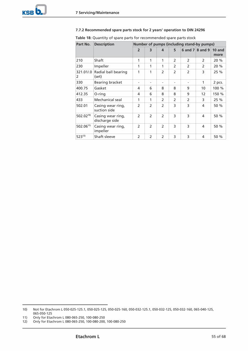
7 Servicing/Maintenance
55 of 68Etachrom L
7.7.2 Recommended spare parts stock for 2 years' operation to DIN 24296
Table 18: Quantity of spare parts for recommended spare parts stock
Part No. Description Number of pumps (including stand-by pumps)
2 3 4 5 6 and 7 8 and 9 10 andmore
210 Shaft 1 1 1 2 2 2 20 %
230 Impeller 1 1 1 2 2 2 20 %
321.01/.02
Radial ball bearing(set)
1 1 2 2 2 3 25 %
330 Bearing bracket - - - - - 1 2 pcs.
400.75 Gasket 4 6 8 8 9 10 100 %
412.35 O-ring 4 6 8 8 9 12 150 %
433 Mechanical seal 1 1 2 2 2 3 25 %
502.01 Casing wear ring,suction side
2 2 2 3 3 4 50 %
502.0210) Casing wear ring,discharge side
2 2 2 3 3 4 50 %
502.0611) Casing wear ring,impeller
2 2 2 3 3 4 50 %
52312) Shaft sleeve 2 2 2 3 3 4 50 %
10) Not for Etachrom L 050-025-125.1, 050-025-125, 050-025-160, 050-032-125.1, 050-032-125, 050-032-160, 065-040-125,065-050-125
11) Only for Etachrom L 080-065-250, 100-080-25012) Only for Etachrom L 080-065-250, 100-080-200, 100-080-250

7 Servicing/Maintenance
56 of 68 Etachrom L
7.7.3 Interchangeability of Etachrom L and Etachrom B pump components
Table 19: Pump components13) Etachrom L
Size
Pum
p c
asin
g
Inte
rmed
iate
pie
ce
Dis
char
ge
cove
r
Foo
t
Sup
po
rt f
oo
t
Shaf
t
Imp
elle
r
Rad
ial b
all b
eari
ng
Dri
ve e
nd
Rad
ial b
all b
eari
ng
Pum
p e
nd
Bea
rin
g b
rack
et
Bea
rin
g c
ove
r D
rive
en
d
Bea
rin
g c
ove
r Pu
mp
en
d
Gas
ket
Join
t ri
ng
Join
t ri
ng
O-r
ing
Mec
han
ical
sea
l
Cas
ing
wea
r ri
ng
Suct
ion
sid
e
Cas
ing
wea
r ri
ng
D
isch
arg
e si
de
Shaf
t sl
eeve
101
132.
01
163
182
183
210
230
321.
02
321.
01
330
360.
02
360.
01
400.
75
411.
77
411.
78
412.
35
433
502.
01
502.
02
523
050-025-125.1 1 ✘ 1* 1 1 1 1* 1 1 1 1 1 ✘ ✘ ✘ 1* 1* 1* ✘ ✘050-025-125 1 ✘ 1* 1 1 1 2* 1 1 1 1 1 ✘ ✘ ✘ 1* 1* 1* ✘ ✘050-025-160 ○ ✘ 5* 2 2 1 3* 1 1 2 1 1 ✘ ✘ ✘ 2* 1* 1* ✘ ✘050-025-200 ○ ✘ 2* 3 3 1 4* 1 1 3 1 1 ✘ ✘ ✘ 3* 1* 7* 1* ✘050-025-250 ○ 1* 3* ✘ 4 2 5* 1 3 4 1 3 ✘ ✘ ✘ 4* 2* 6* 2* ✘050-032-125.1 2 ✘ 1* 1 1 1 1* 1 1 1 1 1 ✘ ✘ ✘ 1* 1* 1* ✘ ✘050-032-125 2 ✘ 1* 1 1 1 2* 1 1 1 1 1 ✘ ✘ ✘ 1* 1* 1* ✘ ✘050-032-160 ○ ✘ 5* 2 2 1 3* 1 1 2 1 1 ✘ ✘ ✘ 2* 1* 1* ✘ ✘050-032-200 ○ ✘ 2* 3 3 1 4* 1 1 3 1 1 ✘ ✘ ✘ 3* 1* 7* 1* ✘050-032-250 ○ 1* 3* ✘ 4 2 5* 1 3 4 1 3 ✘ ✘ ✘ 4* 2* 6* 2* ✘065-040-125 ○ ✘ 1* ○ 1 1 ○* 1 1 1 1 1 ✘ ✘ ✘ 1* 1* 2* ✘ ✘065-040-160 ○ ✘ ○* 2 2 1 ○* 1 1 2 1 1 ✘ ✘ ✘ 2* 1* 8* 1* ✘065-040-200 ○ ✘ 2* ○ 3 1 ○* 1 1 3 1 1 ✘ ✘ ✘ 3* 1* 8* 1* ✘065-040-250 ○ 1* 3* ✘ 4 2 ○* 1 3 4 1 3 ✘ ✘ ✘ 4* 2* 3* 2* ✘065-050-125 ○ ✘ ○* 2 2 1 ○* 1 1 2 1 1 ✘ ✘ ✘ 2* 1* 2* ✘ ✘065-050-160 ○ ✘ ○* ○ 3 1 ○* 1 1 2 1 1 ✘ ✘ ✘ 2* 1* 8* 1* ✘065-050-200 ○ ○* ○* ✘ 3 2 ○* 1 3 4 1 3 ✘ ✘ ✘ ○* 2* 3* 2* ✘065-050-250 ○ 1* 3* ✘ 4 2 ○* 1 3 4 1 3 ✘ ✘ ✘ 4* 2* 3* 2* ✘080-065-200 ○ 1* ○* ✘ 4 2 ○* 1 3 4 1 3 ✘ ✘ ✘ 4* 2* 4* ○* ✘080-065-250 ○ 2* 4* ✘ 5 3 ○* 2 2 5 2 2 1* 1 1 4* 3* 4* 3* 1*
100-080-200 ○ 2* 4* ✘ ○ 3 ○* 2 2 5 2 2 1* 1 1 4* 3* 5* 3* 1*
100-080-250 ○ 2* 4* ✘ 5 3 ○* 2 2 5 2 2 1* 1 1 4* 3* 5* 3* 1*
Table 20: Symbols key
Symbol Description
* Component interchangeable with Etachrom B
○ Components differ
✘ Component not fitted
13) Pump components featuring the same number in a column are interchangeable, i.e. same number = same component

8 Trouble-shooting
57 of 68Etachrom L
8 Trouble-shooting
WARNING
Improper work to remedy faults
Risk of injury!
▷ For any work performed to remedy faults, observe the relevant informationgiven in this operating manual and/or in the product literature provided by theaccessories manufacturer.
If problems occur that are not described in the following table, consultation with theKSB customer service is required.
A Pump delivers insufficient flow rate
B Motor is overloaded
C Excessive discharge pressure
D Increased bearing temperature
E Leakage at the pump
F Excessive leakage at the shaft seal
G Vibrations during pump operation
H Impermissible temperature increase in the pump
Table 21: Trouble-shooting
A B C D E F G H Possible cause Remedy14)
✘ - - - - - - - Pump delivers against an excessivelyhigh pressure.
Re-adjust to duty point.Check system for impurities.Fit a larger impeller.15)
Increase the speed (turbine, I.C. engine).
✘ - - - - - ✘ ✘ Pump or piping are not completelyvented or primed.
Vent or prime.
✘ - - - - - - - Supply line or impeller clogged Remove deposits in the pump and/or piping.
✘ - - - - - - - Formation of air pockets in the piping Alter piping layout.Fit vent valve.
✘ - - - - - ✘ ✘ Suction lift is too high/NPSHavailable
(positive suction head) is too low.Check/alter fluid level.Install pump at a lower level.Fully open the shut-off element in the suctionline.Change suction line, if the friction loss in thesuction line is too high.Check any strainers installed/suction opening.Observe permissible speed of pressure fall.
✘ - - - - - - - Air intake at the shaft seal Fit new shaft seal.
✘ - - - - - - - Wrong direction of rotation Check the electrical connection of the motorand the control system, if any.
✘ - - - - - - - Speed is too low.15)
- Operation with frequency inverter
- Operation without frequency inverter
- Increase voltage/frequency at the frequencyinverter in the permissible range.- Check voltage.
✘ - - - - - ✘ - Wear of internal components Replace worn components by new ones.
- ✘ - - - - ✘ - Pump back pressure is lower thanspecified in the purchase order.
Re-adjust to duty point.In the case of persistent overloading, turndown impeller.15)
- ✘ - - - - - - Density or viscosity of fluid handledhigher than stated in purchase order
Contact KSB.
14) Pump pressure must be released before attempting to remedy faults on parts which are subjected to pressure.15) Contact KSB.

8 Trouble-shooting
58 of 68 Etachrom L
A B C D E F G H Possible cause Remedy14)
- - - - - ✘ - - Use of unsuitable shaft seal materials Change the material combination.15)
- ✘ ✘ - - - - - Speed is too high. Reduce speed.15)
- - - - ✘ - - - Tie bolts/sealing element defective Fit new seal between volute casing anddischarge cover.Re-tighten the bolts.
- - - - - ✘ - - Worn shaft seal Fit new shaft seal.
✘ - - - - ✘ - - Score marks or roughness on shaft sleeve Fit new shaft sleeve. Fit new shaft seal, ifrequired.
- - - - - ✘ - - Dismantle to find out. Correct.Fit new shaft seal, if required.
- - - - - ✘ - - Vibrations during pump operation Correct the suction conditions.Re-align the pump set.Re-balance the impeller.Increase pressure at the pump suction nozzle.
- - - ✘ - ✘ ✘ - Pump set is misaligned. Re-align pump set.
- - - ✘ - ✘ ✘ - Pump is warped or sympatheticvibrations in the piping.
Check piping connections and secure fixing ofpump. Reduce distances between pipe clamps.Fasten the pipes using anti-vibration material.
- - - ✘ - - - - Increased axial thrust15) Clean balancing holes in the impeller.Replace the casing wear rings.
- - - ✘ - - - - Insufficient or excessive quantity oflubricant or unsuitable lubricant
Top up, reduce or change lubricant.
- - - ✘ - - - - Non-compliance with specified couplingdistance
Correct the distance according to generalarrangement drawing.
✘ ✘ - - - - - - Motor is running on 2 phases only. Replace the defective fuse.Check the electric cable connections.
- - - - - - ✘ - Rotor out of balance Clean the impeller.Re-balance the impeller.
- - - - - - ✘ - Defective bearing(s) Replace.
- - - ✘ - - ✘ ✘ Flow rate is too low. Increase the minimum flow rate.

9 Related Documents
59 of 68Etachrom L
9 Related Documents
9.1 Exploded views with list of components
9.1.1 Design for shaft unit 25.1
This view applies to the following pump sizes:
050-025-125.1050-025-125050-025-160050-025-200
050-032-125.1050-032-125050-032-160050-032-200
065-040-125065-040-160065-040-200
065-050-125065-050-160
[ Supplied in packaging units only
1212:12/5
920.95
182 580.02 901.05
930.95
182
6B411.01903.01
580.02901.05
940.01
210 920.95 930.95 940.01/.02
210940.02
321.02
901.99
210 321.01/.02 330 360.01/.02 914.02 920.95 930.95 932.01/.02 940.01/.02
330
360.02
914.02
932.02901.04
183
920.01
502.01
230
433
502.02
101
101 411.01 502.01 903.01
412.35163
163 502.02
360.01
932.01
321.01
732
Table 22: List of components
Part No. Description Part No. Description
101 Pump casing 580.02 Cap
163 Discharge cover 73216) Holder
182 Foot 901.04/.05/.99 Hexagon head bolt
183 Support foot 903.01 Screw plug
210 Shaft 914.02 Round-head screw
230 Impeller 920.01/.95 Nut
321.01/.02 Radial ball bearing 930.95 Safety device
330 Bearing bracket 932.01/.02 Circlip
360.01/.02 Bearing cover 940.01/.02 Key
411.01 Joint ring
412.35 O-ring
433 Mechanical seal Connections
502.01/.0217) Casing wear ring 6B Fluid drain
16) Only for versions with mechanical seal type C1917) Not for Etachrom L 050-025-125.1, 050-025-125, 050-025-160, 050-032-125.1, 050-032-125, 050-032-160, 065-040-125,
065-050-125

9 Related Documents
60 of 68 Etachrom L
9.1.2 Design for shaft unit 25.2
This view applies to the following pump sizes:
050-025-250 050-032-250 065-040-250 065-050-200065-050-250
080-065-200
[ Supplied in packaging units only
901.99
101
101 411.01 502.01 903.01 920.01
920.95230 502.02
163163 502.02
132.01132.01 902.06 920.06
901.99902.06 920.06
914.02
330
210 321.01/.02 330 360.01/.02 901.31 914.02 920.95 930.95 940.01/.02
732
412.35
321.01932.01
360.01901.05
901.31 183
901.04
903.01
411.01
6B
502.01930.95
433
940.01 940.02932.02
321.02
360.02210
210 920.95 930.95 940.01/.02
UG1544581_D01_201/01
Table 23: List of components
Part No. Description Part No. Description
101 Pump casing 73218) Holder
132.01 Intermediate piece 901.04/.05/.31/.99 Hexagon head bolt
163 Discharge cover 902.06 Stud
183 Support foot 903.01 Screw plug
210 Shaft 914.02 Round-head screw
230 Impeller 920.01/.06/.95 Nut
321.01/.02 Radial ball bearing 930.95 Safety device
330 Bearing bracket 932.01/.02 Circlip
360.01/.02 Bearing cover 940.01/.02 Key
411.01 Joint ring
412.35 O-ring
433 Mechanical seal Connections
502.01/.02 Casing wear ring 6B Fluid drain
18) Only for versions with mechanical seal type C19
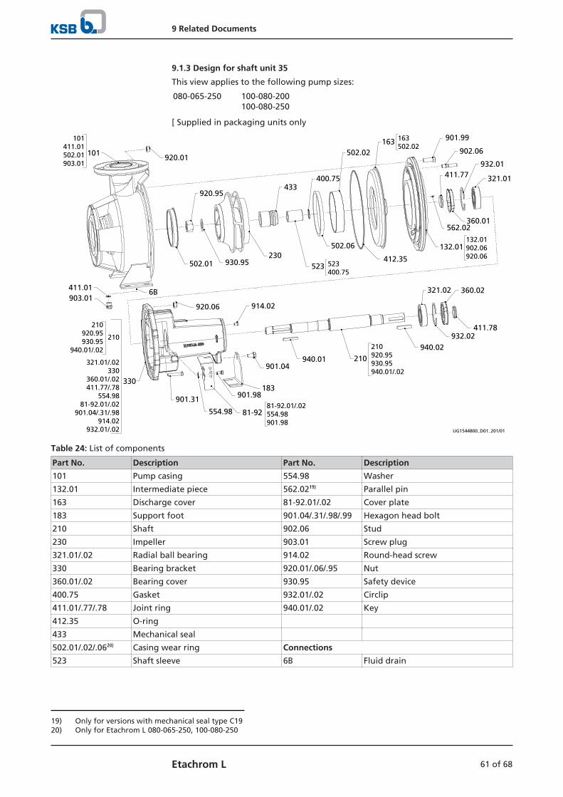
9 Related Documents
61 of 68Etachrom L
9.1.3 Design for shaft unit 35
This view applies to the following pump sizes:
080-065-250 100-080-200100-080-250
[ Supplied in packaging units only
101
101 411.01 502.01 903.01
920.01
920.95433
400.75
502.02163 163
502.02901.99
902.06
411.77932.01
321.01
360.01562.02
132.01132.01 902.06 920.06
502.01 930.95230
502.06
412.35523 523
400.75
321.02 360.02
940.02932.02
411.78
210
210 920.95 930.95 940.01/.02
920.06 914.02
901.31
554.98
901.04
183901.98
81-9281-92.01/.02 554.98 901.98
940.01
411.01903.01
6B
330
210 920.95 930.95
940.01/.02
210
321.01/.02 330
360.01/.02 411.77/.78
554.98 81-92.01/.02
901.04/.31/.98 914.02
932.01/.02 UG1544800_D01_201/01
Table 24: List of components
Part No. Description Part No. Description
101 Pump casing 554.98 Washer
132.01 Intermediate piece 562.0219) Parallel pin
163 Discharge cover 81-92.01/.02 Cover plate
183 Support foot 901.04/.31/.98/.99 Hexagon head bolt
210 Shaft 902.06 Stud
230 Impeller 903.01 Screw plug
321.01/.02 Radial ball bearing 914.02 Round-head screw
330 Bearing bracket 920.01/.06/.95 Nut
360.01/.02 Bearing cover 930.95 Safety device
400.75 Gasket 932.01/.02 Circlip
411.01/.77/.78 Joint ring 940.01/.02 Key
412.35 O-ring
433 Mechanical seal
502.01/.02/.0620) Casing wear ring Connections
523 Shaft sleeve 6B Fluid drain
19) Only for versions with mechanical seal type C1920) Only for Etachrom L 080-065-250, 100-080-250

10 EU Declaration of Conformity
62 of 68 Etachrom L
10 EU Declaration of Conformity
Manufacturer: KSB SE & Co. KGaAJohann-Klein-Straße 9
67227 Frankenthal (Germany)
The manufacturer herewith declares that the product:
Etabloc, Etabloc SYT, Etaline, Etaline SYT, Etaline Z, Etachrom B,Etachrom L, Etanorm, Etanorm SYT, Etanorm V, Etaprime L,
Etaprime B, Vitachrom
KSB order number: ...................................................................................................
▪ is in conformity with the provisions of the following Directives as amended from time to time:
– Pump (set): Machinery Directive 2006/42/EC
The manufacturer also declares that
▪ the following harmonised international standards have been applied:
– ISO 12100
– EN 809
Person authorised to compile the technical file:
NameFunction Address (company)Address (Street, No.)Address (post or ZIP code, city) (country)
The EU Declaration of Conformity was issued in/on:
Place, date
..............................21).............................
Name
Function
CompanyAddress
21) A signed, legally binding EU Declaration of Conformity is supplied with the product.
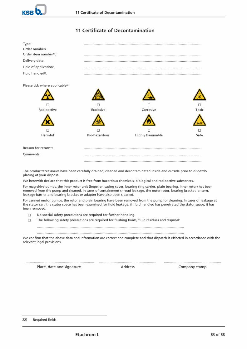
11 Certificate of Decontamination
63 of 68Etachrom L
11 Certificate of Decontamination
Type: ................................................................................................................................
Order number/
Order item number22): ................................................................................................................................
Delivery date: ................................................................................................................................
Field of application: ................................................................................................................................
Fluid handled22): ................................................................................................................................
Please tick where applicable22):
⃞ ⃞ ⃞ ⃞Radioactive Explosive Corrosive Toxic
⃞ ⃞ ⃞ ⃞Harmful Bio-hazardous Highly flammable Safe
Reason for return22): ................................................................................................................................
Comments: ................................................................................................................................
................................................................................................................................
The product/accessories have been carefully drained, cleaned and decontaminated inside and outside prior to dispatch/placing at your disposal.
We herewith declare that this product is free from hazardous chemicals, biological and radioactive substances.
For mag-drive pumps, the inner rotor unit (impeller, casing cover, bearing ring carrier, plain bearing, inner rotor) has beenremoved from the pump and cleaned. In cases of containment shroud leakage, the outer rotor, bearing bracket lantern,leakage barrier and bearing bracket or adapter have also been cleaned.
For canned motor pumps, the rotor and plain bearing have been removed from the pump for cleaning. In cases of leakage atthe stator can, the stator space has been examined for fluid leakage; if fluid handled has penetrated the stator space, it hasbeen removed.
⃞ No special safety precautions are required for further handling.
⃞ The following safety precautions are required for flushing fluids, fluid residues and disposal:
...............................................................................................................................................................
...............................................................................................................................................................
We confirm that the above data and information are correct and complete and that dispatch is effected in accordance with therelevant legal provisions.
.................................................................... ....................................................... .......................................................
Place, date and signature Address Company stamp
22) Required fields
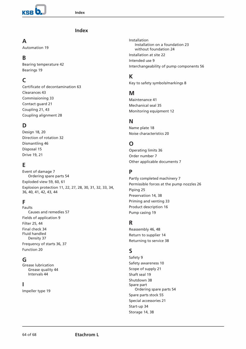
Index
64 of 68 Etachrom L
Index
AAutomation 19
BBearing temperature 42
Bearings 19
CCertificate of decontamination 63
Clearances 43
Commissioning 33
Contact guard 21
Coupling 21, 43
Coupling alignment 28
DDesign 18, 20
Direction of rotation 32
Dismantling 46
Disposal 15
Drive 19, 21
EEvent of damage 7
Ordering spare parts 54
Exploded view 59, 60, 61
Explosion protection 11, 22, 27, 28, 30, 31, 32, 33, 34,36, 40, 41, 42, 43, 44
FFaults
Causes and remedies 57
Fields of application 9
Filter 25, 44
Final check 34Fluid handled
Density 37
Frequency of starts 36, 37
Function 20
GGrease lubrication
Grease quality 44Intervals 44
IImpeller type 19
InstallationInstallation on a foundation 23without foundation 24
Installation at site 22
Intended use 9
Interchangeability of pump components 56
KKey to safety symbols/markings 8
MMaintenance 41
Mechanical seal 35
Monitoring equipment 12
NName plate 18
Noise characteristics 20
OOperating limits 36
Order number 7
Other applicable documents 7
PPartly completed machinery 7
Permissible forces at the pump nozzles 26
Piping 25
Preservation 14, 38
Priming and venting 33
Product description 16
Pump casing 19
RReassembly 46, 48
Return to supplier 14
Returning to service 38
SSafety 9
Safety awareness 10
Scope of supply 21
Shaft seal 19
Shutdown 38Spare part
Ordering spare parts 54
Spare parts stock 55
Special accessories 21
Start-up 34
Storage 14, 38

Index
65 of 68Etachrom L
TTemperature limits 11
Tightening torques 52, 53
Transport 13
WWarnings 8
Warranty claims 7


KSB SE & Co. KGaA
Johann-Klein-Straße 9 • 67227 Frankenthal (Germany)
Tel. +49 6233 86-0
www.ksb.com
1212
.8/1
8-EN
(010
3939
7)


![VENTS KSB EC - folheto187 VENTS. Industrial and commercial ventilation 02201 Point Power [W] KSB 100 EC KSB 125 EC KSB 150 EC KSB 160 EC KSB 200 EC KSB 250 EC KSB 315 EC 1 83 83 83](https://static.fdocuments.net/doc/165x107/5e921ded45cff356a6235202/vents-ksb-ec-folheto-187-vents-industrial-and-commercial-ventilation-02201-point.jpg)