
120214 IEEE Energy Harvesting Vibration
7
Vibration Energy Scavenging and Management for Ultra Low Power Applications * Lu Chao, Chi-Ying Tsui and Wing-Hung Ki Department of Electronic and Computer Engineering The Hong Kong University of Science and Technology Hong Kong SAR., P. R. China {eeluchao, eetsui and eeki}@ee.ust.hk ABSTRACT In this work, the design of a mechanical vibration energy scavenging and management system is presented for ultra low power applications. A new maximum power point tracking (MPPT) scheme is proposed for piezoelectric conversion. This scheme consumes very little power and is especially suitable for ultra low power energy harvesting applications. This design is capable of self-starting and self-powered, thus eliminates external battery integration and significantly reduces the system volume. System modeling, analysis, and VLSI implementation were developed. Various simulations were carried out and the simulation results show that the proposed MPPT scheme can achieve an energy harvesting efficiency higher than 90%. Categories and Subject Descriptors B.7.1 [Integrated Circuits]: Types and Design Styles – Advanced technologies, Algorithms i mplemented in hardware. General Terms Algorithms, Management, Design, Verification. Keywords Energy scavenging and management, MPPT, batteryless 1. INTRODUCTION Ubiquitous applications have potential to be used in many areas, where ubiquitous computing, sensing, and perception facilitate the interaction between human and the environment. Wireless sensor network is a good example. Providing the required supply voltage and power to hundreds or thousands of distributed sensor nodes is a challenge. The conventional solution is to use electrochemical batteries. However, battery has limited energy capacity, relatively large volume with respect to the electronic circuits, finite recharging cycle and is difficult to be replaced regularly in many cases. All the above disadvantages pose a big li mitation on the wide dep loyment of such syste ms. In some ultra low power applications (e.g. picoradio [1], smart dust [2]) that demand compact, low cost, long lifetime and high integration, eliminating the battery is much desirable. For some ubiquitous applications, the average power consumption can be down to the level of hundreds or even tens of microwatts. Power scavenged from the environment can be used as an alternative power source to provide a virtually infinite lifetime [3]. Mechanical energy conversion is one of the feasible approaches for these ultra low power applications [5][6]. Low level vibrations commonly occur in various household or industrial environments, such as machinery or air-conditioning vibration. It is estimated that mechanical vibrations inherent in the environment can provide a power density of tens to hundreds of microwatt per cubic centimeter [4], which is sufficient to sustain operations of many ubiquitous applications [5][6]. Therefore, vibration-based energy scavenging systems have drawn many attentions in the research communities [3]-[7]. Previous studies have found that for piezoelectric conversion, under a given vibration status (magnitude and frequency), there is an optimal output voltage point where maximum harvested electrical power can be obtained [9]. Vibration status is often unstable and varying, and heavily depends on the environment in which the application is located. Hence, the optimal voltage point is also changing. In order to harvest as much energy as possible, a run-time adaptive mechanism is required to track the optimal output voltage with the environmental change. At the same time, this tracking mechanism should have as low power overhead as possible since the ene rgy harvested is alrea dy very small. A vibration based self-powered wireless sensor using a fixed voltage band-band control scheme was proposed in [7]. Existing MPPT schemes for piezoelectric conversion [9][10] are not designed for low power applications because they employed complex circuit components and computation-intensive control algorithms. Hence, they are very inefficient in such low power level and the power overhead could be higher than the maximum power harvested from the environment. In [9], MPPT was controlled by a DSP through comparing the harvested power before and after a change in the duty cycle of a buck converter. The power overhead of the MPPT scheme was not presented. In [10], an expression for the optimal duty cycle of a buck converter operating in discontinuous conduction mode was developed and it revealed that as the level of vibration excitation increases, the optimal duty cycle becomes relatively constant. Based on the above analysis results, a simpler and improved MPPT scheme was developed. The reported power overhead of the tracking unit is 5.74mW and is too much for ultra-low power applications. From this, we can see that in order to facilitate the use of piezoelectric conversion in ultra low power applications, it is necessary to Permission to make digital or hard copies of all or part of this work for personal or classroom use is g ranted without fee provi ded that copies are not made or distributed for profit or commercial advantage and that copies bear this notice and the full citation on the first page. To copy otherwise, or republish, to post on servers or to redistribute to lists, requires prior specific permission and/or a fee. ISLPED’07 , August 27–29, 2007, Portland, Oregon, USA. Copyright 2007 ACM 978-1-59593-709-4/07/0008 …$5.00. * This work was supported in part by the Hong Kong Research Grants Council under Grant CERG 620305. 316
-
Upload
carlo-scoccia -
Category
Documents
-
view
217 -
download
0
Transcript of 120214 IEEE Energy Harvesting Vibration
7/31/2019 120214 IEEE Energy Harvesting Vibration
http://slidepdf.com/reader/full/120214-ieee-energy-harvesting-vibration 1/6
Vibration Energy Scavenging and Managementfor Ultra Low Power Applications *
Lu Chao, Chi-Ying Tsui and Wing-Hung KiDepartment of Electronic and Computer Engineering
The Hong Kong University of Science and TechnologyHong Kong SAR., P. R. China
{eeluchao, eetsui and eeki}@ee.ust.hk
ABSTRACT
In this work, the design of a mechanical vibration energyscavenging and management system is presented for ultra low
power applications. A new maximum power point tracking
(MPPT) scheme is proposed for piezoelectric conversion. This
scheme consumes very little power and is especially suitable for
ultra low power energy harvesting applications. This design iscapable of self-starting and self-powered, thus eliminates external
battery integration and significantly reduces the system volume.
System modeling, analysis, and VLSI implementation weredeveloped. Various simulations were carried out and the
simulation results show that the proposed MPPT scheme can
achieve an energy harvesting efficiency higher than 90%.
Categories and Subject Descriptors
B.7.1 [Integrated Circuits]: Types and Design Styles –
Advanced technologies, Algorithms implemented in hardware.
General Terms
Algorithms, Management, Design, Verification.
Keywords
Energy scavenging and management, MPPT, batteryless
1. INTRODUCTIONUbiquitous applications have potential to be used in many
areas, where ubiquitous computing, sensing, and perceptionfacilitate the interaction between human and the environment.
Wireless sensor network is a good example. Providing the
required supply voltage and power to hundreds or thousands of
distributed sensor nodes is a challenge. The conventional solution
is to use electrochemical batteries. However, battery has limited
energy capacity, relatively large volume with respect to theelectronic circuits, finite recharging cycle and is difficult to be
replaced regularly in many cases. All the above disadvantages
pose a big limitation on the wide deployment of such systems. In
some ultra low power applications (e.g. picoradio [1], smart dust
[2]) that demand compact, low cost, long lifetime and high
integration, eliminating the battery is much desirable.
For some ubiquitous applications, the average power
consumption can be down to the level of hundreds or even tens of
microwatts. Power scavenged from the environment can be usedas an alternative power source to provide a virtually infinite
lifetime [3]. Mechanical energy conversion is one of the feasible
approaches for these ultra low power applications [5][6]. Low
level vibrations commonly occur in various household or
industrial environments, such as machinery or air-conditioningvibration. It is estimated that mechanical vibrations inherent in the
environment can provide a power density of tens to hundreds of
microwatt per cubic centimeter [4], which is sufficient to sustain
operations of many ubiquitous applications [5][6]. Therefore,
vibration-based energy scavenging systems have drawn many
attentions in the research communities [3]-[7].
Previous studies have found that for piezoelectric conversion,under a given vibration status (magnitude and frequency), there is
an optimal output voltage point where maximum harvested
electrical power can be obtained [9]. Vibration status is often
unstable and varying, and heavily depends on the environment in
which the application is located. Hence, the optimal voltage point
is also changing. In order to harvest as much energy as possible, arun-time adaptive mechanism is required to track the optimal
output voltage with the environmental change. At the same time,
this tracking mechanism should have as low power overhead as possible since the energy harvested is already very small.
A vibration based self-powered wireless sensor using a fixed
voltage band-band control scheme was proposed in [7]. ExistingMPPT schemes for piezoelectric conversion [9][10] are not
designed for low power applications because they employed
complex circuit components and computation-intensive control
algorithms. Hence, they are very inefficient in such low power
level and the power overhead could be higher than the maximum
power harvested from the environment. In [9], MPPT wascontrolled by a DSP through comparing the harvested power
before and after a change in the duty cycle of a buck converter.
The power overhead of the MPPT scheme was not presented. In
[10], an expression for the optimal duty cycle of a buck converter
operating in discontinuous conduction mode was developed and itrevealed that as the level of vibration excitation increases, the
optimal duty cycle becomes relatively constant. Based on the
above analysis results, a simpler and improved MPPT scheme was
developed. The reported power overhead of the tracking unit is
5.74mW and is too much for ultra-low power applications. From
this, we can see that in order to facilitate the use of piezoelectricconversion in ultra low power applications, it is necessary to
Permission to make digital or hard copies of all or part of this work for
personal or classroom use is granted without fee provided that copies are
not made or distributed for profit or commercial advantage and that
copies bear this notice and the full citation on the first page. To copy
otherwise, or republish, to post on servers or to redistribute to lists,
requires prior specific permission and/or a fee.
ISLPED’07 , August 27–29, 2007, Portland, Oregon, USA.
Copyright 2007 ACM 978-1-59593-709-4/07/0008 …$5.00.* This work was supported in part by the Hong Kong Research
Grants Council under Grant CERG 620305.
316
7/31/2019 120214 IEEE Energy Harvesting Vibration
http://slidepdf.com/reader/full/120214-ieee-energy-harvesting-vibration 2/6
develop a new MPPT method that has very little power loss and
the corresponding circuit implementation should be simple.
For batteryless vibration based energy harvesting applications,
the feature of self-starting is very crucial since the vibration
sources can be very unstable. Sometimes, there is no vibration or
the vibration excitation is too weak to be used. Thus, no energy
can be harvested. The system will dissipate all the energy storedin the system and stop working. As there is no external battery as
the backup power source, later even the vibration excitation
becomes strong enough again; the system cannot be started up as
there is no power left in the system. Thus the capability of self-
starting is crucial for batteryless applications.
In this paper, we tackle the above design challenges. We present anew MPPT scheme and circuit implementation that have a very
low power overhead, which is in the order of microwatts. This is
about three orders of magnitude lower than the existing MPPT
approaches. Based on this MPPT scheme, a batteryless vibration
based energy scavenging and management system is presented.
The system is capable of self-starting and self-powered. It wasimplemented using a 0.35μm 5V CMOS process. Post-layout
simulations were carried out to verify the functionality and the
efficiency of the proposed MPPT scheme and the overall system.
The rest of the paper is organized as follows. Section 2
introduces the proposed MPPT scheme, and the circuit
implementations of the energy harvester and the vibrationtracking unit. Section 3 describes the proposed batteryless
vibration based energy scavenging and management system. In
addition, the circuit implementation of each functional block is
presented in detail. Various simulation results are presented in
Section 4. Finally, the conclusion is provided in Section 5.
2. The PROPOSED MPPT SCHEME
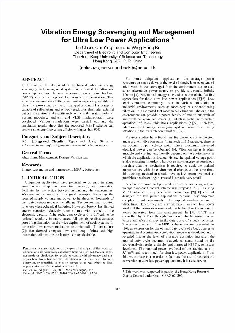
2.1 Electrical Model of Piezoelectric Material
pC p R
0 2 4 6 8 100
1
2
3
4
5
Load Resistance (M Ohms)
O u t p u t v o l t a g e ( V )
Measured
Electrical model
Figure 1 Piezoelectric film model and experimental
verification
Fig. 1(a) shows an equivalent electrical model of a
piezoelectric thin film. It consists of a sinusoidal current source
i(t)=I psin(2πft), where I p depends on the vibration magnitude, size
and material of the film, f is the vibration frequency, C p
and R p
are the internal capacitance and resistance of the film,respectively. Measurement results show that C p is almost constant
under a wide range of vibration frequencies. R p is usually very
large and can be ignored. The output voltage of a piezoelectric
film thus depends on the material’s geometry, piezoelectric
properties, the mechanical vibration strength, and the outputimpedance. We used a commercial piezoelectric thin film [8] to
conduct experiments to verify the above model. A piece of
1.3cm×2.5cm×0.2mm piezoelectric film with C p=0.5nF was
mounted on a variable vibration platform. Various resistive loads
were connected to the film and the peak-to-peak output voltages
were recorded. The measured data are marked in Fig. 1(b). The
output voltages predicted by the model are also plotted. It is clear
that the model fits well with the measurement data. In the rest of
the paper, we use this model for analysis and optimization.
2.2 Energy Harvester
The output of the piezoelectric film is an AC signal. For energyharvesting usage on most CMOS applications, we need an AC-
DC rectifier to convert the input to a DC voltage source for
powering up the circuit. Fig. 2 shows the basic structure of theenergy harvester, which consists of a rectifier and a storage
capacitor Cs. The instantaneously harvested power is small and
may not be able to sustain continuous operations of the
application. Hence, Cs is inserted to accumulate the harvested
power. From [9], it is shown that the time-averaging harvested
power <p(t)> and the output voltage Vs at the maximum input power point are given by
π
π
π
π
π
p s p s s p fC V V fC V V I t p
Δ−−>=<
842)(
2
(1)
V fC
I
V p
p
optimal s Δ−=π 4
, (2)
where ΔV is the forward voltage drop of the diode. For low level
vibration cases, the output voltage of the energy harvester is
comparable to the voltage drop ΔV. The passive diode rectifier causes a significant reduction in the output voltage of the rectifier
and hence the overall power efficiency. In [11], an active diode,
which consists of a large PMOS transistor and a comparator, was
used to reduce the voltage drop and power loss for piezoelectric
conversion. However, an external 3.3V voltage supply was stillrequired for the power supply of the comparator [11]. Thus, this
design is not suitable for batteryless applications since it is not
capable of self-starting. In this work, we propose a hybrid scheme
which uses both passive and active diodes to solve this problem.
The passive diode rectifier is used for the self-starting purpose,while the active diode rectifier kicks in to replace the passivediode when the harvester has started up and it can provide a
smaller voltage drop and higher power efficiency.
)2sin()( ft I t i p π =
Figure 2 Energy Harvester
)2sin()( ft I t i p π =
Figure 3 Schematic of the proposed energy harvester
Fig. 3 shows the schematic of the proposed rectifier [12]. Itintegrates the passive and active diode structures together. During
317

7/31/2019 120214 IEEE Energy Harvesting Vibration
http://slidepdf.com/reader/full/120214-ieee-energy-harvesting-vibration 3/6
the starting up of the system, vibration starts to occur at the
piezoelectric film and AC voltage is generated at the output of the
film. Initially Vs is still zero and cannot drive the operation of the
amplifiers (AMP1, AMP2) and thus the active diodes are not
working. At this time, the PMOS cross-coupled, NMOS diode-connected passive diode rectifier operates and provides
rectification for the AC voltage. The current generated from the
piezoelectric film charges up Cs through the passive rectifier andVs starts to increase. When Vs reaches a level that the amplifiers
can operate, the active diode rectifier is activated. The active
diode will bypass the diode-connected NMOS and reduce thevoltage drop across the rectifier. For the proposed active rectifier,
ΔV is close to zero. Substituting ΔV=0 into (1) and (2), <p(t)>
and optimal Vs are equal to
π
π
π
p s s p fC V V I t p
242
)( >=< (3) p
p
optimal s fC
I V
π 4, = (4)
Expression (4) indicates that the optimal voltage for maximum power harvesting depends on the vibration magnitude I p and
frequency f, which vary with the deployment environment and
time. Thus, the maximum power point is also changing with the
vibration status.2.3 Tracking Unit
The tracking unit is designed to detect the vibration variations
and generate a reference voltage Vref for the MPPT control.Vibration usually does not change very fast and it is not necessary
to track the vibration status continuously. Here we propose a
time-multiplexing scheme to track the vibration status. A tracking
unit, which can reflect the vibration status, is periodically
connected to the piezoelectric material to update the referencevoltage Vref . It is time-multiplexed with the AC-DC rectifier that
during tracking, the power is not harvested from the piezoelectric
film through the rectifier, as the rectifier is disconnected from the
film. To reduce the power overhead of the tracking unit, we use a
very low duty cycle for tracking purpose so that most of the time
the film is providing power through the rectifier. Themultiplexing structure is shown in Fig. 4(a). When the tracking
signal Φ is low, the rectifier is connected to the film and the
system performs energy harvesting. When Φ goes high, the
tracking unit will connect to the film to perform vibration tracking.
The equivalent circuit in this mode is shown in Fig. 4(b).
)2sin()( ft I t i p π = )2sin()( ft I t i p π =
Figure 4 (a) The time-multiplexed structure for the energy
harvester and the tracking unit (b) The vibration tracking
circuit
Figure 5 Illustrative waveforms for the tracking process
In the tracking mode, suppose initially the direction of the
piezoelectric current flow is along the dashed line, as shown in
Fig. 4(b). C p and Cd are discharged, and finally Vd decreases to
zero due to the reverse biased active diode D3. In the next half
cycle, the direction of the current flow is reversed. Hence, C p andCd is charged up again until Vd reaches its peak value. This
positive peak value is maintained as Vref by the capacitor Cr and
the active diode D5, which is similar to the active diode used inthe AC-DC rectifier. Fig. 5 illustrates the tracking process. During
the time period T1, the piezoelectric current discharges Cd. Vd is
reduced and maintained at zero by the active diode D3. Then, inthe next half cycle T2, the current reverses its flow direction, and
Vd is charged up again. At the end of T2, Vd is charged up to its
positive peak value and this value is maintained at Vref .
Let us denote the time instant that i(t) starts to reverse the
flow direction as t=0. The transient response of Vd is analyzed
and expressed as (5),
C Rt
d
C Rt p p
d p p eV e
fC
I ft
fC
I t V
//)0(
2)
22sin(
2)(
−−++−=
π
π
π
π
(5)
where C is the sum of C p and Cd, and Vd(0) is zero. Since R p is
very large and R pC is also very large, the peak value of Vd can beobtained at t=T/2, where T is the cycle time of the vibration and
equation (5) becomes
fC
I t V
p
peak d π
=)( (6)
If we use Cd=15C p, we have V ref = V d (t ) peak =1/4V s,optimal . The time
needed to wait for the piezoelectric current to reverse the flow
direction is at most one vibration cycle. In addition, one half of
the cycle time is needed to obtain the positive peak value of Vd.
Therefore, the minimum duration that the tracking unit needs to be connected to the piezoelectric film (i.e., the pulse width of the
tracking signal Φ) is 1.5T.
3. OVERVIEW of the PROPOSED SYSTEMFig.6 shows the block diagram of the proposed batteryless
vibration based energy scavenging and management system [13].
As we mentioned before, MOS switches (N1, N2, P1) are used toimplement the time-multiplexing MPPT. The duty cycle directly
affects the time that the piezoelectric material can be used for
energy harvesting. Therefore, the duty cycle should be kept as
low as possible. The control unit implements a band-band control
strategy to maintain the output voltage of the energy harvester Vs
at the optimal voltage value by turning on/off the switch S1. The buck converter is used to convert the unregulated voltage Vs into
a regulated output voltage Vout, for the operation of the
application load. Vs is used as the supply voltage for the control
unit, the pulse generator, the tracking unit and the buck converter.
If the harvested power is larger than the power overhead of these blocks, the system can be self-powered without the need of a
battery.
318

7/31/2019 120214 IEEE Energy Harvesting Vibration
http://slidepdf.com/reader/full/120214-ieee-energy-harvesting-vibration 4/6
AC-DC
Rectifier
Buck
Converter
Load
Control
Unit
Vibration
Tracking
Unit
Vs
Cs
S1Piezo
Film
Environmental
Vibration
Vout
con
Vref
enable
. .Vin
Pulse
Generator
.
.
R 1
R 2
Voltage Dividers
Energy Harvester
Tracking
Signal
N1
P1
Refreshing
Unit
.
R 3
R 4
V1
V2
.
.
R 5
R 6
V3
V4
Figure 6 Block diagram of the proposed system
3.1 Tracking Pulse GeneratorSince the vibration frequency varies with the environment, so it
is a challenge to generate a tracking signal Φ with a fixed duty
cycle, while at the same time consuming very low power. In thisdesign, we directly use the AC signals from the piezoelectric film
to generate the tracking signal. The tracking pulse generator is
shown in Fig. 7. We connect one end of the piezoelectric film to a
comparator with a DC bias voltage that is generated by a bandgap
reference and a resistor divider. A clock-like signal, which has thesame frequency as the environmental vibration, is then generatedat the output of the comparator. A counter and combinational
logic gates are used to generate a tracking pulse with a fixed duty
cycle of 1/64, i.e., around 1.56%. In addition, the tracking pulse
width is generated to be 2T to satisfy the minimum requirement of
1.5T for normal tracking.
)2sin()( ft I t i p π =
Figure 7 Block diagram of the tracking pulse generator
3.2 Refreshing UnitIn Fig. 6, there is a refreshing unit located between the tracking
unit and the control unit. It is used to periodically refresh the
stored reference voltage Vref and provide a correctly updatedvoltage V4 to the control unit. As shown in Fig. 4, Vref is kept and
maintained by a capacitor Cr and Vref is updated through an active
diode D5. When the vibration becomes weaker, the active diode is
cut off; and the Vref cannot decrease to reflect the variations of the
vibration. Therefore, we need to refresh the value V ref so that the
tracking unit can generate a correct value of V4 to the control unit.
Fig. 8(a) shows the proposed refreshing unit, which consist of
five MOS switches and an internal capacitor C0. Fig. 8(b) shows
the sequence of control signals that turn on/off the switches.When a new tracking starts, MN2 is on and charge sharing occurs
between Cr and C0. The value of C0 is chosen to be much less than
that of Cr and hence the voltage at C0 is very close to Vref . Note
that the control signal for MN2 is driven by Vs which is about 4
times higher than Vref and hence there is no threshold drop across
the NMOS switch. Before the charge sharing action, C0 isdischarged to 0 by the switch MN1 driven by Con1. After the
charge sharing is completed, the output of the refreshing unit is
connected to C0 through MN4. Cr is cut off from the output. A
Con3 signal is generated to turn on MN3 to discharge Cr . After it
is discharged, it is ready for another tracking update. The tracking
pulse width is 2T and the above action occurs in the first 0.5T.
This leaves enough time for Cr to be charged up to a new V ref .
When the tracking process finishes, i.e., tracking pulse Φ returns
to zero, Vref is already updated and kept by Cr . The output of therefreshing unit is connected back to Cr through MP1 and
disconnected from C0 by turning off MN4.
Figure 8 Schematic of the refreshing circuit and control
signals
3.3 Control UnitThe control unit implements a band-band control strategy to
maintain the output voltage Vs of the energy harvester at theoptimal value. It mainly consists of a Schmitt trigger and a
voltage comparator, as shown in Fig. 9(a). Resistors R 1~R 6 of Fig.
6 form 3 voltage dividers to provide V1= (1/3.95)Vs, V2=
(1/4.05)Vs and V3= (1/3.96)Vs to the control unit. Note that the
refreshing unit provides a reference voltage V4 = (1/4)Vs, optimal tothe control unit as well. Two control signals “con” and “enable”
are generated to turn on/off the switch S1 to track the output
voltage of energy harvester to be optimal and to enable the
application, respectively. When Cs is charged up to a value higher
than 1.0125Vs, optimal, “con” becomes low and turns on S1. It will
trigger the application to wake up from sleep mode and starts an
atomic operation. Power is then transferred to the load through the buck converter. When Vs is lower than 0.99Vs, optimal, “enable”
becomes low to disable the application, which should store the
operation state for next operation before going to sleep mode
again. When Vs is lower than 0.9875Vs, optimal, “con” becomeshigh and turns off S1. Power transfer to the buck converter is
stopped and one operation round is finished. Once the harvested
power charges up Cs and Vs reaches 1.0125Vs, optimal, the operation
cycle repeats again. The control unit maintains Vs between
0.9875~1.0125Vs,optimal.
Figure 9 (a) Control unit diagram (b) Comparator
architecture
The speed of the control unit does not need to be very high and
low power consumption is the most important design factor. Thecomparators are operated in subthreshold region [11], and its
schematic is shown in Fig. 9(b). It contains a two-stage
319

7/31/2019 120214 IEEE Energy Harvesting Vibration
http://slidepdf.com/reader/full/120214-ieee-energy-harvesting-vibration 5/6
operational amplifier and a current source, where the bias current
remains constant even when the power supply changes. Thus, it
guarantees that the bias current of the comparator is small enough
for normal subthreshold operation, even when the supply voltage
changes in a wide range. The operating current for eachcomparator is 60nA. Assume the supply voltage changes in the
range of 2V~6.5V, then, the power dissipation of each comparator
is 120nW to 390nW and the total power overhead of the proposedcontrol unit is about 360nW to 1.17μW.
3.4 Micropower Buck ConverterThe power consumption of ubiquitous applications is in the
range of tens to hundreds of microwatts, while conventional buck converters, which are dedicated for existing portable electronics,
usually consume several hundred milliwatts. Conventional buck
converters are very inefficient in ultra low power level due to
their complicated control algorithms, high power control circuits
and large conduction loss. Consequently, it is necessary to
optimize the structure of buck converters for ultra low power applications.
In this work, an optimized structure for ultra low power
applications is proposed and shown in Fig. 10. Since PWM
control has large power overhead and is inefficient for low power level, so PFM control scheme is used. A ring oscillator is adopted
to perform current-limiting function to reduce the conduction
power loss by the ESR of the inductor. As the averaged current
through the power transistors is only tens or hundreds of microamperes, the sizes of power transistors have to be carefully
chosen to reduce the switching and conduction power loss. In this
design, the optimal W/L ratio of power transistors is
500μm/0.5μm. Besides, the current source is carefully designed to
reduce the static biasing power loss.
Figure 10 Micropower buck converter
3.5 System Start-up and Regular OperationThe self-starting of the energy harvester has been described in
Section 2.2. Fig. 11 illustrates the voltage waveforms for system
starting up and regular operation. When Vs is high enough todrive the tracking pulse generator, the tracking process is
activated and the corresponding V4
is provided to the control unit.
This time instance is marked as t in Fig. 11. From then on, the
system begins the regular operation. In each operation cycle, the
energy transferred to the buck converter and the load can be
estimated as E = ½Cs[(4×1.0125V4)2 – (4×0.9875V4)
2]. Cs should be sized such that it is large enough for the execution of an atomic
operation of the application even under the worst case (i.e. the
lowest allowable output voltage from the rectifier).
Figure 11 Illustrative graphs for overall system operation
4. SIMULATION RESULTSThe proposed energy scavenging and management system was
implemented in AMS 5V 0.35μm CMOS technology and the
layout is shown in Fig. 12(a). We used a piezoelectric film with a
dimension of 1.6cm×6.15cm×3mm. C p is measured to be 33.36nF
and Cs is 5μF. A 47μH inductor was used for the buck converter.The output voltage of the buck converter is set to 1.2V and the
output ripple requirement is less than 25mV. In the active mode,the power consumption of the load is assumed to be 144μW.
4.1 Power Harvesting EfficiencyTo verify the expressions (3) and (4), we simulated the
proposed energy harvester with various resistive loads to find its
power harvesting characteristics. Two sets of vibration status, i.e.,
(60Hz, 70µA) and (60Hz, 100µA) were used and the simulation
results are marked in Fig. 12(b). The harvested power values
predicted by the expression (3) are also plotted in Fig. 12(b). It
can be concluded that the expressions (3) and (4) fit well with the
circuit simulation results.
Buckconverter
Energy
Harvester
Tracking
Unit
Pulse
Generator
0 1 2 3 4 5 6 7 8
0
20
40
60
80
100
120
140
Output Voltage of the Energy Harvester (V)
H a r v e s t e d
P o w e r ( u w )
Power Harvesting Characteristics
(a) (b)
Figure 12 (a) Layout of the proposed overall system (b) Power
harvesting characteristics of the energy harvester
The power harvesting efficiency is defined as the ratio of the
actual harvested power divided by the theoretical maximum
harvested power from the energy harvester. Different sets of
vibration status were used for measuring the power harvestingefficiency. For each set of vibration status, the theoretical
maximum power point was achieved by using the corresponding
optimal resistive load as the load and disabling the MPPT control
blocks and the buck converter. The actual harvested power is
obtained by enabling the MPPT control blocks and providing a
non-optimal resistor as the load. Post-layout HSPICE simulationsof the design were carried to obtain the actual harvested power.
Two vibration status, i.e., (60Hz, 100μA) and (60Hz, 70μA), were
simulated, and the resultant voltage waveforms are shown in Fig.
320

7/31/2019 120214 IEEE Energy Harvesting Vibration
http://slidepdf.com/reader/full/120214-ieee-energy-harvesting-vibration 6/6
13. The harvested power and efficiencies are summarized in
Table 1. The proposed MPPT scheme is also compared with a
fixed voltage band-band control scheme. Here, fixed optimal Vs is
used and it is set at 2.8V that is the optimal voltage for the
vibration status of (60Hz, 70µA). Table 1 shows its actualharvested power.
Figure 13 Vibration tracking waveforms
From Fig. 13 and Table 1, we can see that the tracking unit
tracks well with the vibration status and the obtained optimalvoltages are within 5% of the theoretical values. The power
harvesting efficiency of the proposed MPPT scheme is above
90%. It is also verified that the system is capable of self-starting.
Comparing with the fixed voltage control, the efficiency of the
proposed MPPT scheme is about the same when the fixed voltageis also the optimal voltage. It has about 7% improvement in
efficiency for the case (60Hz, 100μA) that the fixed voltage is not
the optimal voltage. For some other vibration status, the
improvement will be higher. This shows the advantage of the
proposed MPPT that the power overhead of is not high.
Table 1 Tracking Performance of the proposed MPPT scheme
60Hz,100µA 60Hz,70µA
Desired optimal Vs 3.98v 2.78v
Obtained Vs 3.95v 2.81v
Theoretical maximum harvested power 118.1µw 60.07µw
Actual harvested power and energy
harvesting efficiency
110.05µw
93.18%
55.09µw
91.71%
Actual harvested power by fixing Vs=2.8V
and energy harvesting efficiency
102.3µw
86.62%
55.6µw
92.56%
4.2 Performance of the micropower converterThe definition of the power conversion efficiency of the
converter is given by η =loss power power output
power output+
. As the power
dissipation of the ubiquitous applications is usually in the range of
hundreds of microwatts, therefore, very little power overhead canseriously degrade the efficiency of micropower converter. The
buck converter was simulated at various input voltages from 2.5V
to 6V and the power loss curves are plotted in Fig. 14. The power
loss is mainly due to the current source, the conduction loss and
the switching loss of the power transistors. Fig. 14 indicates thatthe power conversion efficiency is about 70%.
2.5 3 3.5 4 4.5 5 5.5 60
20
40
60
80
100
120
140
160
supply voltage (V)
p o w e r ( u w )
Power Characteristics
total power loss
conduction loss
biasing lloss
switching loss
output power
Figure 14 Power loss performance of the buck converter
5. CONCLUSIONWe present a vibration-based power scavenging and
management system for ultra low power ubiquitous applications.
This system is capable of completely self-powered by the
harvested energy and starting up automatically. Circuit
implementation and simulations were carried out to verify the
tracking performance and the feasibility of the proposed platform.
Post-layout simulation shows that the power harvesting efficiency
of the proposed MPPT system is higher than 90%.
6. REFERENCES[1] J. Rabaey, et al., “PicoRadios for wireless sensor networks: the
next challenge in ultra-low-power design”, IEEE Int'l Solid-State
Ckts. Conf., pp.200-201, 2002.
[2] “Smart dust”: Brett Warneke, Berkeley User Archive, April, 2004,
www.bsac.eecs.berkeley.edu/archive/users/warneke-
brett/SmartDust
[3] L. Mateu and F. Moll, “Review of energy harvesting techniques
and applications for microelectronics”, SPIE Microtechnologies
for the New Millennium, pp.359-373, 2005.
[4] S. Roundy, et al., “A study of low level vibrations as a power
source for wireless sensor nodes”, Computer Communications,
pp.1131-1144, 2003.
[5] S. Roundy, P. K. Wright, and J. M. Rabaey, “Energy scavenging
for wireless sensor networks with special focus on vibrations”,Kluwer Academic Publishers, 2004
[6] S. Roundy, et al., “A 1.9GHz RF transmit beacon using
environmentally scavenged energy”, IEEE Int'l Symp. on Low
Power Elec. Device,2003
[7] Eli S. Leland, Elaine M. Lai, et al., “A self-powered wireless
sensor for indoor environment monitoring”, 2004 Wireless
Networking Symposium, 2004
[8] Measurement Specialties, technical manual for piezoelectric film,
http://www.meas-spec.com/.
[9] G.K. Ottman et al., “Adaptive piezoelectric energy harvesting
circuit for wireless remote power supply”, IEEE Trans. on Power
Electronics, vol.17, pp.669-676, 2002
[10] G.K. Ottman et al., “Optimized piezoelectric energy harvesting
circuit using step-down converter in discontinuous conduction
mode”, IEEE Trans. on Power Electronics, pp.696-703, 2003
[11] T. T. Le, J. Han, A. von Jouanne, K. Mayaram and T. S. Fiez,“Piezoelectric micro-power generation interface circuits”, IEEE J.
of Solid-State Circuits, Vol.41, No.6, pp.1411-1420, June 2006.
[12] Yat Hei Lam, Wing Hung Ki, and Chi-Ying Tsui, “Integrated
low-loss CMOS active rectifier for wirelessly power devices”,
IEEE Trans. On Circuits and System II , vol. 53, no. 12, pp. 1378-
1382, Dec. 2006
[13] Lu Chao, Chi-Ying Tsui and Wing Hung Ki, “A batteryless
vibration-based energy harvesting system for ultra low power
ubiquitous applications”, IEEE International Symposium on
Circuits and Systems, May 2007
321


