12000 PG 0706 - Smith Crane & Construction Ltd M12000 - Manufacturer... · model 12000 product ......
28
3 6 10 11 12 13 14 16 25 26 contents Specifications Outline Dimensions Transport Data Crane Assembly Performance Data Load Chart Notes Boom Combinations Range Diagrams and Load Charts Clamshell Crane CARE model 12000 product guide features • 110 t (120 USt) Lift Capacity • 397 mton-m (2,880 ft-kips) Maximum Load Moment • 70,1 m (230 ft) Heavy-Lift Boom • 82,3 m (270 ft) Fixed Jib on Heavy-Lift Boom • 94,5 m (310 ft) Luffing Jib on Heavy-Lift Boom • 247 kW (332 HP) engine • 163 mpm (535 fpm) line speed • 21 180 kg (46,700 lb) Maximum Line Pull • 11 400 kg (25,100 lb) Rated Line Pull • 10 000 kg (25,000 lb) Material Rehandling Clamshell capacity • Fast, efficient self-assembly and disassembly • Manitowoc Crane CARE comprehensive support www.manitowoccranegroup.com
Transcript of 12000 PG 0706 - Smith Crane & Construction Ltd M12000 - Manufacturer... · model 12000 product ......

3
6
10
11
12
13
14
16
25
26
contents
Specifications
Outline Dimensions
Transport Data
Crane Assembly
Performance Data
Load Chart Notes
Boom Combinations
Range Diagrams andLoad Charts
Clamshell
Crane CARE
model 12000productguide
features• 110 t (120 USt) Lift Capacity
• 397 mton-m (2,880 ft-kips)Maximum Load Moment
• 70,1 m (230 ft) Heavy-Lift Boom
• 82,3 m (270 ft) Fixed Jibon Heavy-Lift Boom
• 94,5 m (310 ft) Luffing Jibon Heavy-Lift Boom
• 247 kW (332 HP) engine
• 163 mpm (535 fpm) line speed
• 21 180 kg (46,700 lb) MaximumLine Pull
• 11 400 kg (25,100 lb) Rated LinePull
• 10 000 kg (25,000 lb) MaterialRehandling Clamshell capacity
• Fast, efficient self-assemblyand disassembly
• Manitowoc Crane CAREcomprehensive support
www.manitowoccranegroup.com

notes
2
model12000

specifications
model12000
3Upperworks
Engine
Hino P11C-UN, 6 cylinder, water-cooled diesel, directfuel injection with turbocharger, 247 kW (332 HP) at2000 high-idle RPM. Maximum torque 1300 N•m(959 lb•ft) net at 1,500 rpm (SAE J 1349).
One diesel fuel tank, 400 liters (105 gallons) capacity.
Two 12 volt 136 AH capacity batteries, 24 volt systemand 50 amp alternator.
All wiring harnesses and connectors are numbered foreasier servicing. Machine is equipped with individualfused branch circuits.
Controls
Full-flow hydraulic control system for constant variablepressure to front and rear drums, boom hoist brakesand clutches. Controls respond instantly to the touch,delivering smooth function operation.
Relief valve pressures:Load hoist, boom hoistand propel system . . . . . . . . . . 315kg/cm2 (4,480 psi)Swing system . . . . . . . . . . . . . 280 kg/cm2, (3,980psi)Control system . . . . . . . . . . . . . . 80 kg/cm2 (1,140 psi)
Hydraulic System
All four variable displacement piston-type pumps aredriven by a heavy-duty pump drive. One of thesepumps is used in the right propel circuit and hookhoist circuit, and can accommodate an optional thirdcircuit. Another is used in the left propel circuit andhook hoist circuit. The third variable displacementpump is used in the boom hoist circuit. The fourthvariable displacement pump is used in the swingcircuit. In addition, two gear pumps are used in thecontrol system and auxiliary equipment, and two gearpumps serve the brake cooling system.
Maximum pressure rating . . . . 325 kg/cm2 (4,640 psi)
Load hoist, boom hoist and propel . . . 2 Piston pumpsBoom Hoist . . . . . . . . . . . . . . . . . . . . . . . 1 Piston pumpSwing . . . . . . . . . . . . . . . . . . . . . . . . . 1 Piston pumpControl system and auxiliary . . . . . . . . 2 Gear pumpsBrake cooling system. . . . . . . . . . . . . . 2 Gear pumps
Reservoir capacity: . . . . . . . 460 liter (121 US gallon).
Cooling: Oil-to-air heat exchanger (plate-fin type).
Filtration: Full-flow and bypass type with replaceablepaper element.
Drums
Front and rear drums for load hoist powered byhydraulic variable displacement piston-type motors,driven through planetary reducers. Poweredhoisting/lowering and free-fall operation is standard.Drum turn indicators for front and rear drums are alsostandard.
Brake & Clutches (compatible): Forced-circulation oil-cooled wet-type multi-disc brakes, each using positiveand negative actuation. An external ratchet is fitted forlocking the drums.
Drums: (front and rear) 613 mm (24.1") P.C.D. X 622mm (24.5") wide drums, grooved for 26.0 mm (1.02")wire rope.
Wire rope capacity:Front drum 260 m (853 ft) working lengthRear drum 230 m (754 ft) working lengthStorage length (each drum) 253 m (830')
Line speed: Single line on the first drum layerHoisting: . . . . . . . . . . . . . . . . . . . 120m/min (394 ft/min)Lowering: . . . . . . . . . . . . . . . . . . 120m/min (394 ft/min)
Optional third drum: same dimensions andspecifications as front and rear drums. Wire rope
working length is 240 m (787').
Swing System
Swing unit: Powered by a hydraulic piston-type motordriving spur gears through planetary reducers, theswing system provides 360° rotation.
Swing brake: A spring-set, hydraulically releasedmultiple-disc brake is internally fitted in swing motor.
Swing lock: 2 Position lock for transportation.
Rotating bed turntable: Single-row ball bearing withan integral internally cut swing gear.
Swing speed: 2.7 rpm
Boom Support System
Single drum powered by a hydraulic axial piston motorthrough a planetary reducer.
Brake: A spring-set, hydraulically released multiple-disc brake is internally fitted in the boom hoist motorand operated through a counter-balance valve. Anexternal ratchet is fitted for locking the drum.
Drum: Single drum, grooved for 20 mm (13/16") dia.wire rope. Boom Hoist reeving is 10-part line.

specificationsmodel12000
4Wire Rope Capacity:Drum 155 m (508 ft) working length.
Line speed: Single line on the first drum layer
Hoisting . . . . . . . . . . . . . . . . . . . . 48m/min (157 ft/min)Lowering . . . . . . . . . . . . . . . . . . . . 48m/min (157 ft/min)
Gantry
This high folding type gantry is fitted with a sheaveframe for boom hoist reeving. It provides full up, fulldown positions.
Counterweight
Operator’s Cab
Totally enclosed, full vision cab fitted with tinted safetyglass. A fully adjustable, highbacked seat with armrests permits operators to set their ideal workingposition. Side mounted console for auxiliary controlsand instruments. An air conditioner, a signal horn,cigarette lighter, windshield wiper and inspection lampsocket are standard features.
Controls
In front of operator are the foot pedals for front, rearand third drum (option) brakes and foot throttle pedal.At operator’s right side are the travel (propel) controllevers and the function lock lever. To the operator’sright front are the boom hoist control lever, front andrear winch control levers and the free-fall selectswitches for the front and rear winches and drum turnindicators (front/rear drum). To the operators left frontare the swing control lever and third drum (option)control lever. To the operator’s left are the crawlerextend/retract lever and the positive swing lock. Theleft-hand console contains switches for the anti-two-block/boom overhoist. Directly in front of the consoleare the drum pawl lock for boom, front, rear and thirddrum (option) and the engine ignition key. The swingparking brake and signal horn are mounted on theswing control lever.
GaugesFuel gauge, engine water temperature gauge, hourmeter and tachometer are located on the monitordisplay.
Warning display
All potential warnings, including battery charge,engine oil pressure, air cleaner, engine oil filter,control main pressure, and hydraulic oil temperaturewill appear on the monitor display when a fault occurs.
Safety deviceFunction lock lever, anti-two-block, boom over hoistlimit switch, boom angle indicator, signal horn, boomhoist drum lock, front and rear drum lock, swing lock,swing alarm (buzzer and lamps), boom backstopsand load moment indicator.
Lowerworks
Carbody
The durable carbody features steel weldedconstruction with extendible axles.
Crawlers
Crawler assemblies can be hydraulically extended forwide-track operation or retracted for transportation.Crawler belt tension adjusted with hydraulic jack andmaintained by shims between idler block and frame.
Crawler driveThe independent hydraulic propel drive is built intoeach crawler side frame. Each drive consists of ahydraulic motor driving a propel sprocket through aplanetary gearbox. The hydraulic motor and gearboxare built into the crawler side frame within the shoewidth. The track rollers are sealed for maintenance-free operation.
Crawler brakesSpring set, hydraulically released, multiple disc-typeparking brakes are built into each propel drive.
Steering mechanismThe hydraulic propel system provides both skidsteering (driving one track only) and counter-rotatingsteering (driving each track in opposite direction) anddifferential track speed.
Crawler shoes66 shoes per side, 914 mm (36") wide each crawler.
Travel speed (High/Low) 1.4/1.0 km/h (0.87/0.62 mph)
Attachments
Boom
Welded lattice construction using tubular, high-tensilesteel chords with pin connections between sections.Boom tip is open throat construction. Two idlersheaves and four point sheaves are standard.
UNIT WEIGHT TOTAL WEIGHTQTY. ITEM kg lb kg lb1 Counterweight A 10 000 22,050 10 000 22,0502 Counterweight B 7 000 15,435 14 000 30,8701 Counterweight C 10 000 22,050 10 000 22,050
Counterweight TOTAL 34 000 74,970
specifications
model12000
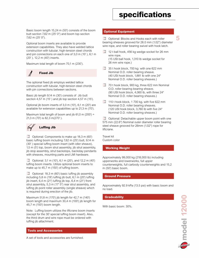
5Basic boom length 15,24 m (50') consists of the boombutt section 7,62 m (25' 0") and boom top section7,62 m (25' 0").
Optional boom inserts are available to provideextension capabilities. They also have welded latticeconstruction with tubular, high-tension steel chordsand pin connections on each one of 3,0 m (10' ), 6,1 m(20' ), 12,2 m (40') inserts.
Maximum total length of boom 70,1 m (230’).
Fixed Jib
The optional fixed jib employs welded latticeconstruction with tubular, high-tension steel chordswith pin connections between sections.
Basic jib length 9,14 m (30') consists of Jib buttsection 4,57 m (15' ) and jib top section 4,57 m (15').
Optional jib boom inserts of 3,0 m (10'), 6,1 m (20') areavailable for extension capabilities up to 21,3 m (70').
Maximum total length of boom and jib 61,0 m (200') +21,3 m (70') is 82,3 m(270' ).
Luffing Jib
Optional: Components to make up 18,3 m (60')basic luffing boom including 7,62 m (25') butt, 9,14 m(30' ) special luffing boom insert (with idler sheave),1,5 m (5') top, boom strut assembly, jib strut assembly,jib stop assembly, strut backstops, backstay pendantswith sheaves, mounting parts and LMI hardware.
Optional: 3,1 m (10'), 6,1 m (20'), and 12,2 m (40')luffing boom inserts. Utilize optional boom inserts tomake up to 45,7 m (150') of luffing boom.
Optional: 18,3 m (60') basic luffing jib assemblyincluding 5,8 m (19') luffing jib butt, 6,1 m (20') luffingjib insert, 6,4 m (21') luffing jib top, 6,4 m (21') frontstrut assembly, 5,3 m (17' 5") rear strut assembly, andluffing jib point roller assembly (single sheave) whichis required during erection of the jib.
Maximum 51,8 m (170') jib length for 42,7 m (140')boom length and maximum 30,4 m (100') jib length for45,7 m (150') boom length.
Note: Luffing boom utilizes the liftcrane boom inserts(except for the 30' special luffing boom insert). Also,the third drum and wire rope must be ordered withluffing jib attachment.
Tools and Accessories
A set of tools and accessories are furnished.
Optional Equipment
Optional: Blocks and Hooks each with rollerbearing sheaves grooved for 26.0 mm (1.02") diameterwire rope, and roller bearing swivel with hook latch.
12 t ball hook, 456 kg wedge socket for 26 mmwire rope.(15 USt ball hook, 1,310 lb wedge socket for26 mm wire rope.)
35 t hook block, 700 kg with one 622 mmNominal O.D. roller bearing sheave.(40 USt hook block, 1,881 lb with one 24"Nominal O.D. roller bearing sheaves.)
70 t hook block, 900 kg, three 622 mm NominalO.D. roller bearing bearing sheave.(90 USt hook block, 4,060 lb, with three 24"Nominal O.D. roller bearing sheaves.)
110 t hook block, 1 700 kg, with five 622 mmNominal O.D. roller bearing sheaves.(120 USt hook block, 3,760 lb with five 24"Nominal O.D. roller bearing sheaves.)
Optional: Detachable upper boom point with one575 mm (22.6") Nominal outer diameter roller bearingsteel sheave grooved for 26mm (1.02") rope forliftcrane.
Travel kitCustom color
Working Weight
Approximately 99,000 kg (218,000 lb) includingupperworks and lowerworks, full uppercounterweights, full carbody counterweights and 15,2m (50') basic boom.
Ground Pressure
Approximately 92.9 kPa (13.5 psi) with basic boom andno load.
Gradeability
With basic boom: 30%.

outline dimensionsmodel12000
6
24'3
"(7
,38
m)
11'6
"(3
,50
m)
19' 0" (5,80 m)
22' 2" (6,77 m)
BasicBoom
50' (15,24 m)
3' 7"
(1,10 m)
R=16' 5" (5,00 m)
19' 11" (6,07 m)
11' 3"
(3,42 m)
7'3"
(2,2
0m
)
4'2"
(1,2
6m
)
13' 6" (4,21 m) Retracted17' 5" (5,30 m) Extended
1' 1" (,33 m)
10' 6" (3,2 m)
11'5
"(3
,50
m)
3' (0,90 m)

Option
outline dimensions
model12000
7Upperworks without Crawlers x 1Length 15,12 m 49' 7"Width 3,24 m 10' 8"Height 3,15 m 10' 4"Weight 42 661 kg 94,052 lb
Note: Weight includes base machine, gantry, maximum hoistand whip lines on drums, boom butt, full hydraulic fluidreservoir, and one third tank of fuel. rweighounterweight
Crawlers x 2Length 6,77 m 22' 3"Width 0,90 m 3' 0"Height 1,15 m 3' 9"Weight 11 830 kg 26,085 lb
Hydraulic Jack (if removed) x 4Length 1,36 m 4' 5"Width 0,32 m 1' 1"Height 0,96 m 3' 2"Weight 430 kg 950 lb
Upper Counterweight A x 1Length 3,20 m 10' 5"Width 0,58 m 1' 11"Height 1,94 m 6' 4"Weight 10 000 kg 22,050 lb
Upper Counterweight B x 2Length 3,20 m 10' 5"Width 0,49 m 1' 7"Height 1,92 m 6' 3"Weight 7 000 kg 15,435 lb
Upper Counterweight C x 1Length 3,20 m 10' 5"Width 0,69 m 2' 3"Height 1,92 m 6' 3"Weight 10 000 kg 22,050 lb
Optional 3rd Drum & Wire Rope x 1Weight 2 660 kg 5,865 lb
Boom Butt 7.6m (25') x 1Length 7,79 m 26' 3"Width 1,68 m 5' 6"Height 2,06 m 6' 9"Weight 2 110 kg 4,652 lb
L
H
L
H
L
H
W
H
L
L
W
H
WL
H
L
H

Option
outline dimensionsmodel12000
8Boom Top 7.6m (25') x 1Length 8,32 m 27' 4"Width 1,68 m 5' 6"Height 1,69 m 5' 7"Weight 1 525 kg 3,362 lb
Boom Insert 3,0 m (10') x 1, 2Length 3,17 m 10' 5"Width 1,68 m 5' 6"Height 1,69 m 5' 7"Weight 380 kg 838 lb
Boom Insert 6,1m (20') x 1, 2Length 6,22 m 20' 5"Width 1,68 m 5' 6"Height 1,69 m 5' 7"Weight 655 kg 1,445 lb
Boom Insert 12,2 m (40') x 1, 2, 3Length 12,31 m 40' 5"Width 1,68 m 5' 6"Height 1,69 m 5' 7"Weight 1 195 kg 2,635 lb
Note: Use one “A” type insert with lug required for any boomcombinations that require a 12,2 m (40') insert.
Fixed Jib Butt x 1Length 4,81 m 15' 9"Width 0,80 m 2' 8"Height 0,80 m 2' 8"Weight 200 kg 440 lb
Fixed Jib Top x 1Length 4,91 m 16' 1"Width 0,80 m 2' 8"Height 0,80 m 2' 8"Weight 280 kg 617 lb
Fixed Jib Insert 3,0 m (10') x 1, 2Length 3,12 m 10' 3"Width 0,80 m 2' 8"Height 0,80 m 2' 8"Weight 100 kg 220 lb
Fixed Jib Insert 6,1 m (20') x 1, 2Length 6,16 m 20' 3"Width 0,80 m 2' 8"Height 0,80 m 2' 8"Weight 180 kg 395 lb
Fixed Jib Strut x 1Length 3,62 m 11' 11"Height 0,62 m 2' 0"Weight 250 kg 550 lb
L
H
L
H
L
H
L
H
L
H
L
H
L
H
L
H
L
H
Option
outline dimensions
model12000
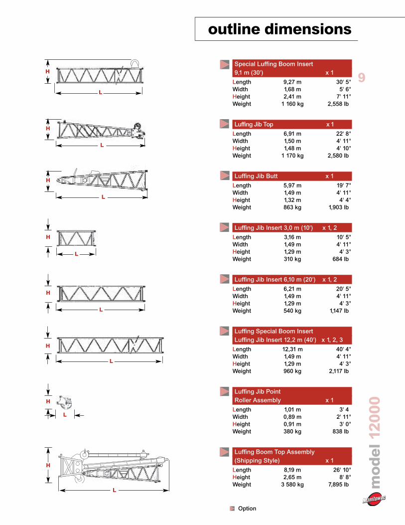
9Special Luffing Boom Insert9,1 m (30') x 1Length 9,27 m 30' 5"Width 1,68 m 5' 6"Height 2,41 m 7' 11"Weight 1 160 kg 2,558 lb
Luffing Jib Top x 1Length 6,91 m 22' 8"Width 1,50 m 4' 11"Height 1,48 m 4' 10"Weight 1 170 kg 2,580 lb
Luffing Jib Butt x 1Length 5,97 m 19' 7"Width 1,49 m 4' 11"Height 1,32 m 4' 4"Weight 863 kg 1,903 lb
Luffing Jib Insert 3,0 m (10') x 1, 2Length 3,16 m 10' 5"Width 1,49 m 4' 11"Height 1,29 m 4' 3"Weight 310 kg 684 lb
Luffing Jib Insert 6,10 m (20') x 1, 2Length 6,21 m 20' 5"Width 1,49 m 4' 11"Height 1,29 m 4' 3"Weight 540 kg 1,147 lb
Luffing Special Boom InsertLuffing Jib Insert 12,2 m (40') x 1, 2, 3Length 12,31 m 40' 4"Width 1,49 m 4' 11"Height 1,29 m 4' 3"Weight 960 kg 2,117 lb
Luffing Jib PointRoller Assembly x 1Length 1,01 m 3' 4Width 0,89 m 2' 11"Height 0,91 m 3' 0"Weight 380 kg 838 lb
Luffing Boom Top Assembly(Shipping Style) x 1Length 8,19 m 26' 10"Height 2,65 m 8' 8"Weight 3 580 kg 7,895 lb
L
H
L
H
L
H
L
H
L
H
L
H
L
H
L
H

10
model12000
transport data
Item
No. 12000 Basic Cranewith Crawlers Removed
Crawler Frame
Crawler Frame
Counterweight A
Counterweight B
Counterweight B
Counterweight C
12,2 m (40') No. 12000Boom Insert, Pendants
12,2 m (40') No. 12000Boom Insert, Pendants
12,2 m (40') No. 12000Boom Insert, Pendants
6,1 m (20') No. 12000Boom Insert, Pendants
6,1 m (20') No. 12000Boom Insert, Pendants
3,0 m (10') No. 12000Boom Insert, Pendants
3,0 m (10') No. 12000Boom Insert, Pendants
Standard Boom Top7,6 m (25')
Upper BoomPoint
4,6 m (15’) No. 12000Fixed Jib Top
4,6 m (15’) No. 12000Fixed Jib Butt
6,1 m (20’) No. 12000Fixed Jib Insert
6,1 m (20’) No. 12000Fixed Jib Insert
kg (lb)
42 661(94,052)
11 832(26,085)
12 832(26,085)
10 000(22,050)
7 000(15,435)
7 000(15,435)
10 000(22,050)
1 209(2,635)
1 209(2,635)
1 209(2,635)
655(1,445)
655(1,445)
380(838)
380(838)
1,525(3,362)
501(1,105)
280(617)
134(440)
179(395)
179(395)
1
1
42661
(94,052)
2
1
1
1
13594
(29,558)
3
1
1
1
4
1
1
1
1
5
1
1
1
1
6
1
1
1
1
1
13528
(29,825)
8655
(19,082)
18038
(39,768)
12561
(27,692)Approximate Total
Shipping Weight kg (lb)
Trailer Load Out Summary
Model 12000No. 12000 Luffing Jib 39,6 m (130') on No. 260 Boom 38,1 m (125')
Weight Quantity oneach Item Trailer Load #

11
model12000
crane assembly

performance datamodel12000
12

13
model12000
load chart notes
1. Rated loads included in the charts are the maximum allowable
freely suspended loads at a given boom length, boom angle
and load radius, and have been determined for the machine
standing level on firm supporting surface under ideal operating
conditions. The user must limit or de-rate rated loads to allow
for adverse conditions (such as soft or uneven ground, out-of-
level conditions, wind, side loads, pendulum action, jerking or
sudden stopping of loads, inexperience of personnel, multiple
machine lifts, and traveling with a load).
2. Capacities do not exceed 75% of minimum tipping loads.
Capacities based on factors other than machine stability such
as structural competence are shown by asterisk * in the chartslocated in the operator’s crane cab.
3. The machine must be reeved and set-up as stated in the
operation manual and all the instruction manuals. If these
manuals are missing, obtain replacements. Boom backstops
are required for all boom lengths. Gantry must be in the fully
raised position for all operations. Crawlers must be fully
extended and be locked in position. The crane must be
leveled to within 1% on a firm supporting surface.
4. Do not attempt to lift where no radius or load is listed as crane
may tip or collapse.
5. Attempting to lift more than rated loads may cause machine
to tip or collapse. Do not tip machine to determine capacity.
6. Weight of hooks, hook blocks, slings and other lifting devices
are a part of the total load. Their total weight must be subtract-
ed from the rated load to obtain the weight that can be lifted.
7. When lifting over boom point with jib or upper boom point
installed, rated loads for the boom must be deducted as
shown below.
8. The total load that can be lifted by the fixed jib is limited by
rated jib loads. The total load that can be lifted with the upper
boom point is limited by rated upper boom point loads.
9. Boom lengths for fixed jib mounting are 27,4 m (90 ft) to 61,0 m
(200 ft).
10. The total load that can be lifted by the upper boom point is: the
rated load for the luffing jib (without upper boom point installed)
minus 386 kg (850 lbs); however, the upper boom point rated load
should not exceed 11 300 kg (25,000 lbs).
11. An upper boom point cannot be used on a 70,1 m (230 ft)
boom length.
12. The boom should be erected over the front of the crawlers,
not IateraIIy.
13. Least stable position is over the side.
14. Maximum hoist load for number of reeving parts of line for
hoist rope.
Maximum Load for Main Boom
Maximum Load for Upper Boom Point (On Luffing Jib)
Maximum Load for Upper Boom Point (On Liftcrane Boom)
15. Lifting capacities listed apply only to the machine as originally
manufactured for and supplied by Manitowoc Cranes, Inc.
Modifications to this machine or use of equipment other than
that specified can reduce operating capacity.
16. Designed and rated to comply with ANSI Code B30.5.
Operation of this equipment in excess of rated loads or
disregard of instruction voids the warranty.
Maximum Load for Luffing Jib
Luffing Jib Point Roller Pin Connected Boom Point Sheave
Deduct kg (lbs) 386 (850) 218 (480)
When lifting over luffing jib point with luffing jib roller assembly or pin
connected boom point sheave (on the luffing boom top) attached,
rated loads for the jib and sheave must be deducted as shown below.
Minimum Weight of Hook Block Required for Lowering.(Luffing Jib Use)
Maximum Load for Fixed Jib
Jib length m Upper Boom 9,1 12,2 15,2 18,3 21,3(ft) Point (30) (40) (50) (60) (70)
Deduct kg 318 1 100 1 500 2 000 2 400 2 900(lbs) (700) (2,400) (3,200) (4,200) (5,200) (6 200)
No. of Parts of Line 1 2 3 4 5
Maximum Loads kg 11 300 22 600 33 900 45 200 56 500(Ibs) (25,000) (50,000) (75,000) (100,000) (125,000)
No. of Parts of Line 6 7 8 9 10
Maximum Loads m 67 800 79 100 90 400 101 700 110 000(Ibs) (150,000) (175,000) (200,000) (225,000) (240,000)
Maximum Loads kg 11 300 22 600 33 900 36 200(Ibs) (25,000) (50,000) (75,000) (80,000)
No. of Parts of Line 1 2 3 4
(Ibs) (24,000)
No. of Parts of Line 1
Maximum Loads m 10 800
Maximum Loads kg 11 300 22 600(Ibs) (25,000) (50,000)
No. of Parts of Line 1 2
Maximum Loads kg 11 300(Ibs) (25,000)
No. of Parts of Line 1
No. of Parts of Line 1 2 3 4
Maximum Loads m 272 544 680 800(Ibs) (600) (1,200) (1,500) (1,800)

boom combinationsmodel12000
143,1m(10 ft)
–
1
–
1
–
6,1m(20 ft)
–
–
1
1
2
12000
Boom Lengthm (ft)
15,2 (50)
18,3 (60)
21,3 (70)
24,4 (80)
27,4 (90)
30,5 (100)
33,5 (110)
36,6 (120)
39,6 (130)
42,7 (140)
45,7 (150)
48,8 (160)
51,8 (170)
54,9 (180)
57,9 (190)
61,0 (200)
64,0 (210)
67,0 (220)
70,1 (230)
3,1 m(10 ft)
–
1
2
1
2
1
2
1
2
1
2
1
2
1
2
1
2
1
2
6,1 m(20 ft)
–
–
1
1
1
2
2
1
1
2
2
1
1
2
2
1
1
2
2
12,2 m(40 ft)
–
–
–
–
–
–
–
1*
1*
1*
1*
2*
2*
2*
2*
3*
3*
3*
3*
Boom Inserts
Model 12000Main Boom
70,1 m (230 ft)
7,6 m (25 ft)Boom Butt
12,2 m (40 ft)Boom Insert
6,1 m (20 ft)Boom Insert
3,0 m (10 ft)Boom Insert
12,2 m (40 ft)Boom Insert
12,2 m (40 ft)Boom Insert
7,6 m (25 ft)No. 12000Boom Top
Model 12000Main Boom
70,1 m (230 ft)
12000
Model 12000Fixed Jib on Main Boom
82,3 m (270 ft)
4,6 m (15 ft)Jib Top
4,6 m (15 ft)Jib Butt
Model 12000Fixed Jib
21,3 m (70 ft)
3,0 m (10 ft)Boom Insert
12,2 m (40 ft)Boom Insert
6,1 m (20 ft)Boom Insert
12,2 m (40 ft)Boom Insert
12,2 m (40 ft)Boom Insert
7,6 m (25 ft)Boom Top
*Note: One 40 ft. (12,2 m) boom insert withlug (40A) is required for fixed jib. When no jibis installed a 40 ft (12,2 m) boom can be usedinstead of 40A.
6,1 m (20 ft)Jib Insert
Jib Lengthm (ft)
9,1 (30)
12,2 (40)
15,2 (50)
18,3 (60)
21,3 (70)
No. 12000 Fixed JibCombinations
Fixed Jib Inserts
7,6 m (25 ft)Boom Butt
Model 12000Main Boom
61,0 m (200 ft)
3,0 m (10 ft)Boom Insert
6,1 m (20 ft)Boom Insert
6,1 m (20 ft)Jib Insert
No. 12000 Heavy-LiftBoom Combinations

boom combinations
model12000
15
12000
Model 12000Luffing Jib onLuffing Boom94,5 m (310 ft)
3,0 m (10 ft)Jib Insert
2,1 m (5 ft)Jib Top
5,79 m (19 ft)Jib Butt
Model 12000Luffing Jib
51,8 m (170 ft)
9,1 m (30 ft)Special Luffing BoomInsert
12,2 m (40 ft)Boom Insert
Model 12000Luffing Boom42,7 m (140 ft)
6,1 m (20 ft)Jib Insert
7,6 m (25 ft)Boom Butt
6,4 m (21 ft)Jib Top
12,2 m (40 ft)Boom Insert
6,1 m (20 ft)Jib Insert
Luffing
Jib Lengthm (ft)
18,3 (60)
21,3 (70)
24,4 (80)
27,4 (90)
30,5 (100)
33,5 (110)
36,6 (120)
39,6 (130)
42,7 (140)
45,7 (150)
48,8 (160)
51,8 (170)
3,0 m(10 ft)
–
1
2
1
2
1
2
1
2
1
2
1
6,1 m(20 ft)
–
–
–
1
1
–
–
1
1
–
–
1
12,2 m(40 ft)
–
–
–
–
–
1
1
1
1
2
2
2
Boom Inserts
No. 12000 Luffing JibCombinations
Luffing
Boom Lengthm (ft)
18,3 (60)
21,3 (70)
24,3 (80)
27,4 (90)
30,5 (100)
33,5 (110)
36,6 (120)
39,6 (130)
42,7 (140)
45,7 (150)
3,0 m(10 ft)
–
1
2
1
2
1
2
1
2
1
6,1 m(20 ft)
–
–
–
1
1
2
2
1
1
2
9,1 m(30 ft)
1*
1*
1*
1*
1*
1*
1*
1*
1*
1*
Boom Inserts
No. 12000 Luffing BoomCombinations
*Note: One 9,14 m (30') special luffing boominsert is required for luffing boom.
12,2 m(40 ft)
–
–
–
–
–
–
–
1
1
1
12,2 m (40 ft)Boom Insert
12,2 m (40 ft)Boom Insert
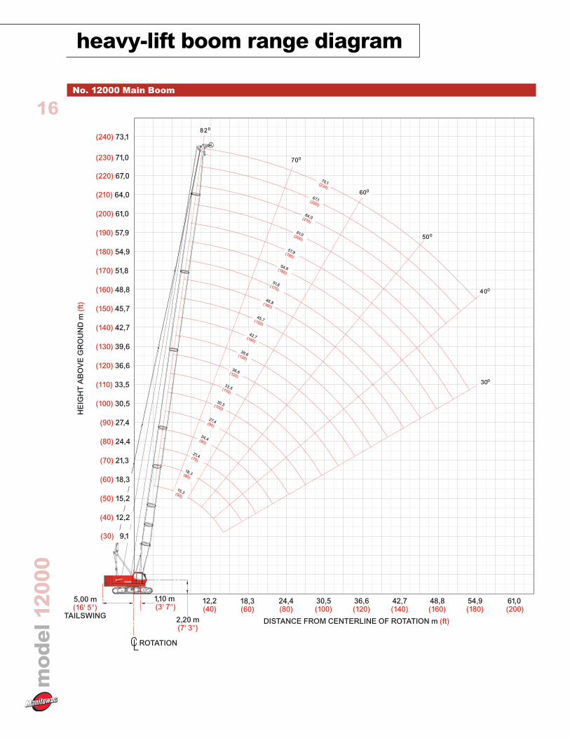
heavy-lift boom range diagrammodel12000
16No. 12000 Main Boom
12000
TAILSWING
5,00 m(16' 5")
2,20 m(7' 3")
1,10 m(3' 7")
ROTATION
HE
IGH
TA
BO
VE
GR
OU
ND
m(f
t)
(40) 12,2
(30) 9,1
(200) 61,0
(180) 54,9
(160) 48,8
(140) 42,7
(120) 36,6
(100) 30,5
(80) 24,4
(60) 18,3
(190) 57,9
(210) 64,0
(220) 67,0
(230) 71,0
(240) 73,1
(170) 51,8
(150) 45,7
(130) 39,6
(110) 33,5
(90) 27,4
(70) 21,3
(50) 15,2
DISTANCE FROM CENTERLINE OF ROTATION m (ft)
48,8(160)
54,9(180)
61,0(200)
42,7(140)
36,6(120)
30,5(100)
24,4(80)
18,3(60)
12,2(40)
820
700
600
500
400
300
39,6(130)
42,7(140)
45,7(150)
48,8(160)
36,6(120)
33,5(110)
30,5(100)
61,0(200)
64,0(210)
67,1(220)
70,1(230)
57,9(190)
54,9(180)
51,8(170)
27,4(90)
24,4(80)
21,4(70)
18,3(60)
15,3(50)
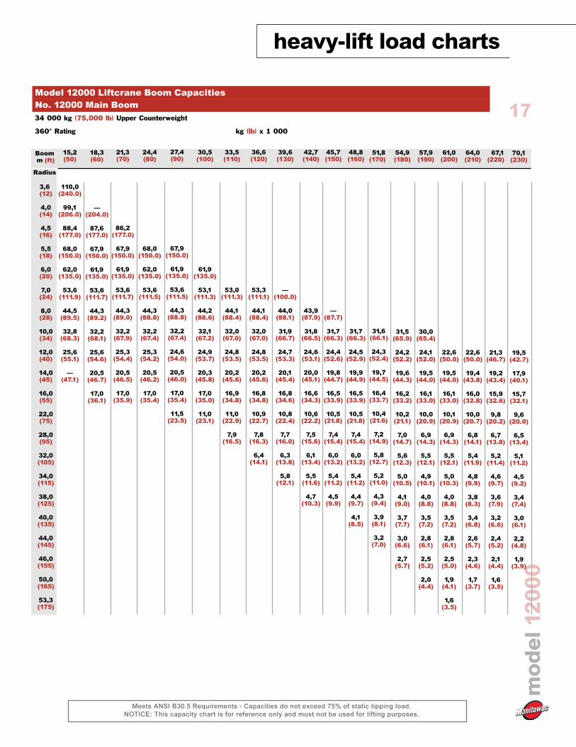
heavy-lift load charts
model12000
Meets ANSI B30.5 Requirements - Capacities do not exceed 75% of static tipping load.NOTICE: This capacity chart is for reference only and must not be used for lifting purposes.
17
Boomm (ft)
Radius
3,6(12)
4,0(14)
4,5(16)
5,5(18)
6,0(20)
7,0(24)
8,0(28)
10,0(34)
12,0(40)
14,0(45)
16,0(55)
22,0(75)
28,0(95)
32,0(105)
34,0(115)
38,0(125)
40,0(135)
44,0(145)
46,0(155)
50,0(165)
53,3(175)
15,2(50)
110,0(240.0)
99,1(206.0)
88,4(177.0)
68,0(150.0)
62,0(135.0)
53,6(111.9)
44,5(89.5)
32,8(68.3)
25,6(55.1)
—(47.1)
18,3(60)
—(204.0)
87,6(177.0)
67,9(150.0)
61,9(135.0)
53,6(111.7)
44,3(89.2)
32,2(68.1)
25,6(54.6)
20,5(46.7)
17,0(36.1)
21,3(70)
86,2(177.0)
67,9(150.0)
61,9(135.0)
53,6(111.7)
44,3(89.0)
32,2(67.9)
25,3(54.4)
20,5(46.5)
17,0(35.9)
Model 12000 Liftcrane Boom CapacitiesNo. 12000 Main Boom34 000 kg (75,000 lb) Upper Counterweight
360° Rating kg (lb) x 1 000
70,1(230)
19,5(42.7)
17,9(40.1)
15,7(32.1)
9,6(20.0)
6,5(13.4)
5,1(11.2)
4,5(9.2)
3,4(7.4)
3,0(6.1)
2,2(4.8)
1,9(3.9)
51,8(170)
31,6(66.1)
24,3(52.4)
19,7(44.5)
16,4(33.7)
10,4(21.6)
7,2(14.9)
5,8(12.7)
5,2(11.0)
4,3(9.4)
3,9(8.1)
3,2(7.0)
54,9(180)
31,5(65.9)
24,2(52.2)
19,6(44.3)
16,2(33.2)
10,2(21.1)
7,0(14.7)
5,6(12.3)
5,0(10.5)
4,1(9.0)
3,7(7.7)
3,0(6.6)
2,7(5.7)
57,9(190)
30,0(65.4)
24,1(52.0)
19,5(44.0)
16,1(33.0)
10,0(20.9)
6,9(14.3)
5,5(12.1)
4,9(10.1)
4,0(8.8)
3,5(7.2)
2,8(6.1)
2,5(5.2)
2,0(4.4)
61,0(200)
22,6(50.0)
19,5(44.0)
16,1(33.0)
10,1(20.9)
6,9(14.3)
5,5(12.1)
5,0(10.3)
4,0(8.8)
3,5(7.2)
2,8(6.1)
2,5(5.0)
1,9(4.1)
1,6(3.5)
64,0(210)
22,6(50.0)
19,4(43.8)
16,0(32.8)
10,0(20.7)
6,8(14.1)
5,4(11.9)
4,8(9.9)
3,8(8.3)
3,4(6.8)
2,6(5.7)
2,3(4.6)
1,7(3.7)
24,4(80)
68,0(150.0)
62,0(135.0)
53,6(111.5)
44,3(88.8)
32,2(67.4)
25,3(54.2)
20,5(46.2)
17,0(35.4)
27,4(90)
67,9(150.0)
61,9(135.0)
53,6(111.5)
44,3(88.8)
32,2(67.4)
24,6(54.0)
20,5(46.0)
17,0(35.4)
11,5(23.5)
30,5(100)
61,9(135.0)
53,1(111.3)
44,2(88.6)
32,1(67.2)
24,9(53.7)
20,3(45.8)
17,0(35.0)
11,0(23.1)
39,6(130)
—(100.0)
44,0(88.1)
31,9(66.7)
24,7(53.3)
20,1(45.4)
16,8(34.6)
10,8(22.4)
7,7(16.0)
6,3(13.8)
5,8(12.1)
45,7(150)
—(87.7)
31,7(66.3)
24,4(52.6)
19,8(44.7)
16,5(33.9)
10,5(21.8)
7,4(15.4)
6,0(13.2)
5,4(11.2)
4,5(9.9)
48,8(160)
31,7(66.3)
24,5(52.9)
19,9(44.9)
16,5(33.9)
10,5(21.8)
7,4(15.4)
6,0(13.2)
5,4(11.2)
4,4(9.7)
4,1(8.5)
42,7(140)
43,9(87.9)
31,8(66.5)
24,6(53.1)
20,0(45.1)
16,6(34.3)
10,6(22.2)
7,5(15.6)
6,1(13.4)
5,5(11.6)
4,7(10.3)
33,5(110)
53,0(111.3)
44,1(88.4)
32,0(67.0)
24,8(53.5)
20,2(45.6)
16,9(34.8)
11,0(22.9)
7,9(16.5)
67,1(220)
21,3(46.7)
19,2(43.4)
15,9(32.6)
9,8(20.2)
6,7(13.8)
5,2(11.4)
4,6(9.7)
3,6(7.9)
3,2(6.6)
2,4(5.2)
2,1(4.4)
1,6(3.5)
36,6(120)
53,3(111.1)
44,1(88.4)
32,0(67.0)
24,8(53.5)
20,2(45.6)
16,8(34.8)
10,9(22.7)
7,8(16.3)
6,4(14.1)

fixed jib range diagram
18
model12000
No. 12000 Fixed Jib on Main Boom
12000
TAILSWING
5,09 m(16' 5")
2,20 m(7' 3")
1,10 m (3' 7")
ROTATION
HE
IGH
TA
BO
VE
GR
OU
ND
m(f
t)
(40) 12,2
(200) 61,0
(220) 67,1
(240) 73,2
(260) 79,2
(270) 82,3
(280) 85,3
(180) 54,9
(160) 48,8
(140) 42,7
(120) 36,6
(100) 30,5
(80) 24,4
(60) 18,3
(190) 57,9
(210) 64,0
(230) 70,1
(250) 76,2
(170) 51,8
(150) 45,7
(130) 39,6
(110) 33,5
(90) 27,4
(70) 21,3
(50) 15,2
DISTANCE FROM CENTERLINE OF ROTATION m (ft)
48,8(160)
54,9 (180)
60,1 (200)
42,7(140)
36,6(120)
30,5 (100)
24,4 (80)
18,3 (60)
12,2 (40)
(30) 9,1
61,0(200)
64,0(210)
67,1(220)
70,1(230)
57,9(190)
54,9(180)
51,8(170)
48,8(160)
45,7(150)
42,7(140)
39,6(130)
36,6(120)
70 0
80 0
60 0
50 0
40 0
73.2(240)
67,1(250)
79,2(260)
82,3(270)
30 0
30 0
10 0
21,3(70)
15,2(50)
9,1(30)
18.3(60)
12,2(40)

fixed jib load charts
19
model12000
Meets ANSI B30.5 Requirements - Capacities do not exceed 75% of static tipping load.NOTICE: This capacity chart is for reference only and must not be used for lifting purposes.
Model 12000 Series 2 Liftcrane Fixed Jib CapacitiesNo. 12000 Fixed Jib on Main Boom34 000 kg (75,000 lb) Counterweight
360° Rating kg (lb) x 1 000
10˚ Offset 30˚ Offset
27,4(90)
10,8(24.0)
10,8(24.0)
10.8(24.0)
10.8(24.0)
10,1(21.9)
7,4(16.1)
36,6(120)
10,8(24.0)
10,8(24.0)
10,8(24.0)
9,7(21.1)
7,1(15.3)
5,3(11.6)
48,8(160)
10,8(24.0)
10,8(24.0)
9,3(20.1)
6,6(14.2)
4,8(10.4)
3,6(7.8)
2,7(5.8)
2,2(—)
Boomm (ft)
Radius
10,0(30)
12,0(40)
14,0(50)
18,0(60)
24,0(80)
30,0(100)
36,0(120)
42,0(140)
48,0(160)
52,0(175)
56,0(185)
Jib9,1m(30ft)
54,9(180)
—(24.0)
10,8(24.0)
9,0(19.8)
6,3(13.6)
4,5(9.8)
3,3(7.1)
2,3(4.9)
1,7(3.6)
61,0(200)
—(24.0)
10,8(24.0)
8,8(19.0)
6,1(13.1)
4,3(9.3)
3,0(6.5)
2,0(4.2)
1,5(—)
27,4(90)
—(21.0)
9,5(21.0)
9,5(21.0)
8,6(18.9)
36,6(120)
9,5(21.0)
9,5(21.0)
9,4(20.8)
7,2(15.6)
48,8(160)
9,5(21.0)
9,4(20.8)
6,8(14.7)
5,0(10.7)
Boomm (ft)
Radius
10,0(30)
12,0(40)
14,0(50)
18,0(60)
24,0(80)
30,0(100)
36,0(120)
42,0(140)
48,0(160)
52,0(175)
56,0(185)
Jib9,1m(30ft)
54,9(180)
9,5(21.0)
9,2(20.2)
6,5(14.1)
4,7(10.2)
3,4(7.4)
61,0(200)
—(21.0)
9,1(19.9)
6,4(13.7)
4,5(9.7)
3,2(7.0)
2,3(—)
27,4(90)
9,0(—)
9,0(20.0)
9,0(20.0)
9,0(20.0)
7,7(16.8)
6,2(13.6)
5,2(11.5)
36,6(120)
9,0(—)
9,0(20.0)
9,0(20.0)
8,9(19.5)
7,2(15.7)
5,5(11.9)
4,3(9.3)
48,8(160)
9,0(20.0)
9,0(20.0)
9,0(20.0)
6,8(14.7)
5,0(10.8)
3,8(8.2)
2,9(6.2)
2,3(4.9)
1,8(4.1)
Boomm (ft)
Radius
10,0(30)
12,0(40)
14,0(50)
18,0(60)
24,0(80)
30,0(100)
36,0(120)
42,0(140)
48,0(160)
52,0(175)
58,0(185)
Jib15,2m(50ft)
54,9(180)
9,0(20.0)
9,0(20.0)
6,5(14.1)
4,7(10.2)
3,5(7.5)
2,5(5.4)
1,9(4.0)
61,0(200)
9,0(20.0)
8,9(19.7)
6,3(13.6)
4,5(9.8)
3,3(7.1)
2,2(4.7)
1,6(3.3)
27,4(90)
5,1(11.4)
5,1(11.2)
4,4(9.8)
36,6(120)
5,1(11.4)
5,1(11.2)
4,8(10.6)
4,3(9.6)
48,8(160)
5,1(—)
5,1(11.4)
5,1(11.4)
4,7(10.4)
4,0(8.6)
Boomm (ft)
Radius
10,0(30)
12,0(40)
14,0(50)
18,0(60)
24,0(80)
30,0(100)
36,0(120)
42,0(140)
48,0(160)
52,0(175)
58,0(185)
Jib15,2m(50ft)
54,9(180)
5,1(11.4)
5,1(11.4)
4,9(10.8)
3,7(8.1)
2,7(5.9)
61,0(200)
5,1(11.4)
5,1(11.4)
4,9(10.6)
3,6(7.7)
2,5(5.3)
1,9(3.8)

fixed jib load charts
20
model12000
Meets ANSI B30.5 Requirements - Capacities do not exceed 75% of static tipping load.NOTICE: This capacity chart is for reference only and must not be used for lifting purposes.
Model 12000 Series 2 Liftcrane Fixed Jib CapacitiesNo. 12000 Fixed Jib on Main Boom34 000 kg (75,000 lb) Counterweight
360° Rating kg (lb) x 1 000
10˚ Offset 30˚ Offset
27,4(90)
7,1(15.7)
6,7(14.8)
6,4(13.9)
5,5(11.5)
4,4(9.4)
3,7(7.9)
3,2(7.1)
36,6(120)
6,8(15.1)
6,6(14.4)
6,3(13.3)
5,1(10.9)
4,3(9.2)
3,7(8.2)
3,2(6.8)
48,8(160)
6,9(15.4)
6,7(14.8)
6,5(14.3)
6,0(12.7)
4,7(9.7)
3,6(7.9)
2,7(5.6)
2,2(4.8)
2,0(4.0)
1,6(3.3)
Boomm (ft)
Radius
12,0(45)
18,0(60)
22,0(75)
26,0(90)
32,0(110)
38,0(130)
44,0(145)
50,0(170)
54,0(180)
56,0(190)
60,0(200)
Jib21,3m(70ft)
54,9(180)
7,0(15.6)
6,8(15.0)
6,6(14.4)
6,0(12.3)
4,4(9.1)
3,3(7.2)
2,4(4.7)
1,8(3.9)
1,6(—)
61,0(200)
7,1(15.7)
6,9(15.1)
6,7(14.6)
5,8(11.9)
4,2(8.6)
3,1(6.8)
2,0(4.1)
27,4(90)
3,6(—)
3,6(8.1)
3,5(7.6)
3,0(6.5)
2,7(—)
36,6(120)
3,6(8.1)
3,6(8.1)
3,3(7.0)
2,9(6.3)
2,6(5.9)
48,8(160)
3,6(8.1)
3,5(7.6)
3,1(6.9)
2,9(6.4)
2,6(5.9)
Boomm (ft)
Radius
12,0(45)
18,0(60)
22,0(75)
26,0(90)
32,0(110)
38,0(130)
44,0(145)
50,0(170)
54,0(180)
56,0(190)
60,0(200)
Jib21,3m(70ft)
54,9(180)
3,6(8.1)
3,6(7.8)
3,2(7.1)
3,0(6.6)
2,7(5.5)
2,1(4.5)
61,0(200)
3,6(8.1)
3,6(8.0)
3,3(7.3)
3,0(6.8)
2,5(4.9)
1,8(3.9)
1,6(—)
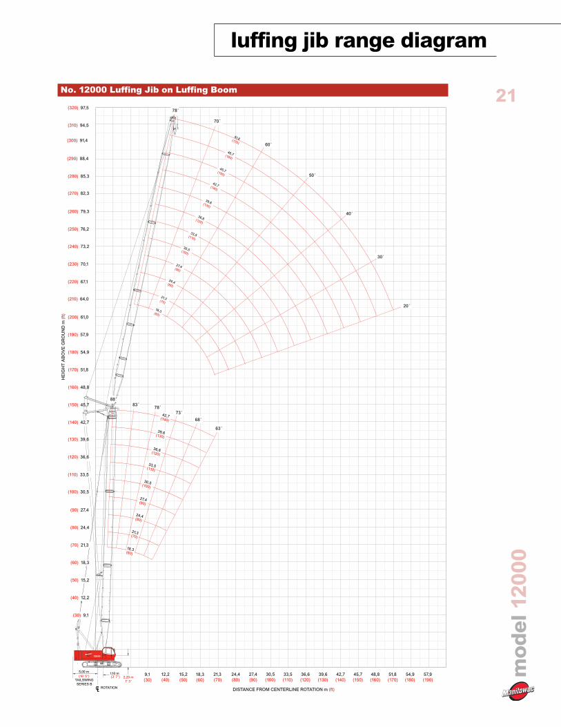
luffing jib range diagram
model12000
21No. 12000 Luffing Jib on Luffing Boom
12000
1,10 m (3' 7")(16' 5")
5,00 m
TAILSWINGSERIES B
2,20 m7' 3"
ROTATION
57,9(190)
88 ˚
78 ˚73 ˚
83 ˚
68 ˚
63 ˚
33,5(110)
30,5(100)
21,3(70)
27,4(90)
24,4(80)
36,6(120)
42,7(140)
39,6(130)
18,3(60)
45,7(150)
48,7(160)
51,8(170)
(200) 61,0
(210) 64,0
(230) 70,1
(220) 67,1
(240) 73,2
(250) 76,2
(260) 79,3
(190) 57,9
(180) 54,9
(170) 51,8
(160) 48,8
(150) 45,7
(140) 42,7
(90) 27,4
(100) 30,5
(120) 36,6
(110) 33,5
(130) 39,6
(80) 24,4
(70) 21,3
(60) 18,3
(50) 15,2
(40) 12,2
(30) 9,1
45,7(150)
48,8(160)
51,8(170)
54,9(180)
42,7(140)
39,6(130)
36,6(120)
33,5(110)
30,5(100)
27,4(90)
24,4(80)
21,3(70)
18,3(60)
15,2(50)
12,2(40)
9,1(30)
DISTANCE FROM CENTERLINE ROTATION m (ft)
HE
IGH
TA
BO
VE
GR
OU
ND
m(f
t)
(270) 82,3
(280) 85,3
(290) 88,4
(300) 91,4
(310) 94,5
(320) 97,5
20 ˚
30 ˚
40 ˚
50 ˚
60 ˚
70 ˚
78 ˚
18,3(60)
21,3(70)
24,4(80)
27,4(90)
42,7(140)
33,5(110)
30,5(100)
36,6(120)
39,6(130)

luffing jib load chartsmodel12000
Meets ANSI B30.5 Requirements - Capacities do not exceed 75% of static tipping load.NOTICE: This capacity chart is for reference only and must not be used for lifting purposes.
22
18,2(60)
36,2(80.0)
31,9(69.3)
28,8(57.7)
20,4(46.2)
14,1(—)
11,2(—)
24,4(80)
—(80.0)
31,9(69.3)
28,7(57.7)
20,5(46.2)
14,4(26.9)
11,3(—)
30,5(100)
31,9(69.3)
28,7(57.7)
20,5(46.2)
14,6(27.3)
11,5(—)
36,6(120)
31,9(69.3)
28,7(57.7)
20,5(46.2)
14,8(27.6)
11,8(—)
Boomm (ft)
Radius
7,9(26)
9,0(30)
10,0(36)
14,0(45)
18,0(65)
20,0(80)
24,0(80)
30,0(100)
36,0(120)
44,0(145)
LuffingJibLength18,3m(60ft)
Model 12000 Series 2 Liftcrane Luffing Jib CapacitiesNo. 12000 Luffing Jib on Luffing Boom34 000 kg (75,000 lb) Counterweight
360° Rating kg (lb) x 1 000
88 ˚ Boom Angle
18,2(60)
—(57.7)
20,5(46.2)
14,7(28.0)
9,4(20.3)
6,4(13.7)
24,4(80)
20,5(46.2)
15,0(28.4)
9,4(20.3)
6,4(13.7)
30,5(100)
20,5(46.2)
15,2(28.9)
9,5(20.5)
6,4(13.7)
5,4(—)
36,6(120)
20,5(46.2)
15,4(29.1)
9,6(20.7)
6,4(13.7)
5,5(—)
Boomm (ft)
Radius
7,9(26)
9,0(30)
10,0(36)
14,0(45)
18,0(65)
24,0(80)
30,0(100)
32,0(120)
36,0(120)
44,0(145)
LuffingJibLength
30,5m(100ft)
18,2(60)
20,7(46.2)
17,7(36.8)
10,9(22.7)
7,3(15.2)
5,0(10.6)
3,4(8.2)
24,4(80)
20,7(46.2)
17,9(37.5)
11,0(22.9)
7,4(15.4)
5,1(10.6)
3,4(8.2)
30,5(100)
20,7(46.2)
17,9(37.5)
11,2(23.1)
7,4(15.4)
5,1(10.6)
3,4(8.2)
Boomm (ft)
Radius
14,0(45)
16,0(55)
22,0(75)
28,0(95)
34,0(115)
40,0(130)
44,0(150)
50,0(165)
52,0(175)
56,0(190)
LuffingJibLength
39,6m(130ft)
18,2(60)
—(30.0)
10,3(21.6)
6,8(14.1)
4,6(9.7)
3,2(7.3)
2,6(4.9)
—(2.2)
24,4(80)
—(30.2)
10,4(21.8)
6,9(14.3)
4,6(9.7)
3,2(7.3)
2,6(4.0)
30,5(100)
10,4(22.0)
6,9(14.3)
4,7(9.7)
3,2(7.3)
1,6(—)
Boomm (ft)
Radius
14,0(45)
16,0(55)
22,0(75)
28,0(95)
34,0(115)
40,0(130)
44,0(150)
50,0(165)
52,0(175)
56,0(190)
LuffingJibLength
51,8m(170ft)
45,7(150)
19,5(42.5)
17,9(36.4)
12,9(29.1)
9,5(18.3)
7,9(—)
45,7(150)
12,6(28.4)
9,6(19.0)
6,6(14.3)
4,5(9.7)
3,9(—)
36,6(120)
17,1(36.4)
11,3(23.4)
7,5(15.7)
5,1(10.8)
3,4(8.2)
36,6(120)
10,6(22.3)
7,0(14.6)
4,7(9.7)
2,6(6.2)

luffing jib load charts
Meets ANSI B30.5 Requirements - Capacities do not exceed 75% of static tipping load.NOTICE: This capacity chart is for reference only and must not be used for lifting purposes.
23Model 12000 Series 2 Liftcrane Luffing Jib CapacitiesNo. 12000 Luffing Jib on Luffing Boom34 000 kg (75,000 lb) Counterweight
360° Rating kg (lb) x 1 000
73˚ Boom Angle
18,2(60)
—(35.9)
13,0(29.1)
11,5(24.0)
24,4(80)
12,4(27.6)
11,0(23.1)
8,5(19.6)
30,5(100)
10,4(22.3)
8,4(18.7)
7,4(—)
36,6(120)
—(20.3)
8,0(17.9)
7,2(15.2)
Boomm (ft)
Radius
16,0(55)
20,0(65)
22,0(75)
26,0(85)
28,0(95)
32,0(105)
34,0(115)
38,0(125)
40,0(135)
42,0(140)
LuffingJibLength18,3m(60ft)
18,2(60)
8,8(19.6)
7,9(16.8)
6,6(14.6)
5,9(12.8)
24,4(80)
8,1(17.9)
7,5(15.9)
6,2(13.7)
5,6(11.9)
4,7(—)
30,5(100)
6,9(15.0)
5,8(13.0)
5,3(11.2)
4,5(9.9)
36,6(120)
—(13.0)
5,4(12.1)
4,9(10.4)
4,1(9.0)
3,8(7.9)
Boomm (ft)
Radius
16,0(55)
20,0(65)
22,0(75)
26,0(85)
28,0(95)
32,0(105)
34,0(115)
38,0(125)
40,0(135)
42,0(140)
LuffingJibLength
30,5m(100ft)
18,2(60)
—(15.2)
6,3(13.9)
5,7(12.1)
4,8(10.6)
4,4(9.3)
3,7(8.2)
24,4(80)
5,8(13.0)
5,3(11.2)
4,5(9.9)
4,1(8.6)
3,5(7.7)
3,2(—)
30,5(100)
—(11.2)
5,0(10.6)
4,2(9.3)
3,8(7.9)
3,1(6.8)
2,8(6.0)
2,6(—)
Boomm (ft)
Radius
28,0(95)
32,0(105)
34,0(115)
38,0(125)
40,0(135)
44,0(145)
46,0(155)
48,0(160)
52,0(175)
56,0(185)
LuffingJibLength
39,6m(130ft)
18,2(60)
—(10.1)
4,3(9.5)
3,9(8.4)
3,2(7.1)
2,9(6.2)
2,7(5.7)
2,2(4.6)
1,7(—)
24,4(80)
3,8(8.4)
3,6(7.5)
2,9(6.4)
2,6(5.5)
2,4(5.1)
1,8(4.0)
1,5(3.3)
30,5(100)
—(6.6)
2,9(6.6)
2,5(5.5)
2,2(4.6)
1,9(4.2)
1,5(3.3)
Boomm (ft)
Radius
28,0(95)
32,0(105)
34,0(115)
38,0(125)
40,0(135)
44,0(145)
46,0(155)
48,0(160)
52,0(175)
56,0(185)
LuffingJibLength
51,8m(170ft)
36,6(120)
4,2(9.3)
3,7(8.2)
3,4(7.1)
2,8(6.2)
2,5(5.3)
2,3(4.9)
36,6(120)
2,2(4.9)
2,1(4.6)
1,8(4.0)
1,7(3.5)
45,7(150)
6,9(15.4)
6,6(13.9)
5,3(11.9)
45,7(150)
4,2(9.3)
4,1(9.0)
3,5(7.7)
3,1(6.6)
2,8(6.2)
model12000

luffing jib load chartsmodel12000
Meets ANSI B30.5 Requirements - Capacities do not exceed 75% of static tipping load.NOTICE: This capacity chart is for reference only and must not be used for lifting purposes.
24Model 12000 Series 2 Liftcrane Luffing Jib CapacitiesNo. 12000 Luffing Jib on Luffing Boom34 000 kg (75,000 lb) Counterweight
360° Rating kg (lb) x 1 000
63˚ Boom Angle
18,2(60)
—(22.5)
9,7(21.2)
8,6(19.4)
24,4(80)
7,9(17.6)
7,4(15.7)
30,5(100)
—(13.7)
5,5(12.3)
36,6(120)
4,7(10.4)
4,6(9.7)
Boomm (ft)
Radius
22,0(75)
24,0(80)
26,0(85)
28,0(95)
32,0(105)
34,0(115)
38,0(125)
40,0(135)
44,0(145)
46,0(150)
LuffingJibLength18,3m(60ft)
18,2(60)
6,0(13.4)
5,5(11.7)
4,7(10.4)
24,4(80)
4,8(10.6)
4,2(9.3)
3,9(8.2)
30,5(100)
3,5(7.9)
3,3(7.1)
2,8(6.2)
36,6(120)
2,4(5.3)
2,2(4.9)
2,0(4.4)
Boomm (ft)
Radius
22,0(75)
24,0(80)
26,0(85)
28,0(95)
32,0(105)
34,0(115)
38,0(125)
40,0(135)
44,0(145)
46,0(150)
LuffingJibLength
30,5m(100ft)
18,2(60)
—(9.7)
4,4(9.7)
4,0(9.0)
3,6(7.9)
3,4(7.1)
2,9(—)
24,4(80)
3,2(7.1)
3,1(6.8)
2,9(6.0)
2,4(5.1)
2,1(—)
30,5(100)
—(4.6)
2,0(4.6)
1,9(4.0)
1,7(3.3)
1,5(3.1)
Boomm (ft)
Radius
36,0(120)
38,0(125)
40,0(130)
42,0(140)
44,0(150)
48,0(160)
50,0(170)
52,0(175)
54,0(180)
58,0(190)
LuffingJibLength
39,6m(130ft)
18,2(60)
—(5.1)
2,2(4.9)
2,0(4.0)
1,7(3.7)
1,6(3.3)
—(2.9)
Boomm (ft)
Radius
36,0(120)
38,0(125)
40,0(130)
42,0(140)
44,0(150)
48,0(160)
50,0(170)
52,0(175)
54,0(180)
58,0(190)
LuffingJibLength
51,8m(170ft)
45,7(150)
—(6.4)
2,9(6.4)

25
model12000
clamshell
1. Figures represent maximum allowable capacity, and assume level ground and ideal working conditions.2. Capacities are calculated at 66% of the minimum tipping loads.3. Capacities are maximum recommended by PCSA Standard #4. Allowances must be made by the user for such unfavorable
conditions as a soft or uneven supporting surface, rapid cycle operations, or bucket suction.4. The combined weight of the bucket and load must not exceed these capacities.5. Boom length for clamshell operation should not exceed 30,5 m (100 ft).
Boom Component Chart
Boom length ft (m) Boom arrangement15,2 (50) Base-Tip18,3 (60) Base-A-Tip21,3 (70) Base-A-A-Tip, Base-B-Tip24,4 (80) Base-A-B-Tip27,4 (90) Base-A-A-B-Tip, Base-B-B-Tip, Base-C-Tip
30,5 (100) Base-A-B-B-Tip, Base-A-C-Tip
Base = 7,6 m (25 ft)Insert: A = 3,05 m (10 ft )
B = 6,10 m (20 ft)C = 12,2 m (40 ft)
Tip = 7,2 m (25 ft)
Boom:Welded lattice construction using tubular, high-tensile steelchords with pin connections between sections.Basic boom length: 15,2 m (50 ft)Max. boom length: 30,5 m (100 ft)Limit on clamshell bucket weight: 2 100 kg (4,600 lbs)
Load Radius
Centerof
Rotation
Clamshell Capacities10 000 kg (22,050 lb) Counterweight (One UpperCounterweight, Crawlers Extended)
kg (lb) x 1 00015,2(50)
10,0(25.0)
10,0(25.0)
10,0(25.0)
10,0(25.0)
10,0(23.1)
18,3(60)
10,0(25.0)
9,7(25.0)
7,8(22.9)
6,6(19.8)
5,7(12.5)
Boomm (ft)
Radius
7,0(22)
8,0(26)
9,0(30)
10,0(34)
14,0(45)
15,0(50)
17,0(55)
18,0(60)
21,0(70)
24,0(80)
25,0(85)
27,0(90)
21,3(70)
9,7(25.0)
7,8(22.7)
6,6(19.6)
5,7(17.2)
5,0(15.2)
24,4(80)
7,8(22.5)
6,6(19.4)
5,7(17.0)
5,0(15.0)
4,4(11.9)
27,4(90)
7,8(21.6)
6,6(19.2)
5,7(16.8)
5,0(14.8)
4,3(11.7)
—(9.5)
30,5(100)
6,6(18.5)
5,7(16.5)
5,0(14.6)
4,2(11.5)
—(9.3)
—(8.4)
—(7.7)

Crane CARE is Manitowoc’s comprehensive service andsupport program. It includes classroom and on-sitetraining, prompt parts availability, expert field service,technical support and documentation — for every one ofthe more than 7,000 Manitowoc cranes currently in usethroughout the world.
That’s commitment you won’t find anywhere else.
That’s Crane CARE.
Service Training
Manitowoc specialists work with you in our trainingcenter and in the field to make sure you know how to getmaximum performance, reliability and life from yourcranes.
Manitowoc Cranes Technical Training Center providesvaluable multi-level training, which is available for allmodels and attachments, in the following format:
• Basic – Provides technicians with the basic skillsrequired in our Level I and II classes coveringhydraulic and electrical theory and schematics, pump,motor, control, and LMI operation, and the use of metersand gauges.
• Level 1 – This model-specific class covers theoryand offers hands-on training and trouble shooting forall crane systems.
• Level 2 – This model-specific class provides indepth coverage of all crane systems and components,and advanced troubleshooting of simulated faults.(Requires Level 1.)
• Level 3/Master – Covering all EPIC models and the4100W, this class stresses high level system knowledgeand trouble shooting of simulated faults.(Requires Level 2.)
Parts Availability
Genuine Manitowoc replacement parts are accessiblethrough your distributor 24 hours a day, 7 days a week,365 days a year.
Service Interval KitsProvides all the parts required by Manitowoc’sPreventative Maintenance Checklist.
Hydraulic Filter Kit
Consists of the following:• Filter Element - Hydraulic in Tank (4)
Cummins Model QSZ15-C600 Diesel
– Service Interval Kits
200 Hour KitConsists of the following:
Engine• Filter Oil (1)• Filter Water (1)• Filter Fuel (1)
1,000 Hour KitConsists of the following:
Engine• Filter Air Cleaner - Primary (1)• Filter Oil (1)• Filter Water (14)• Filter Fuel (1)
Hydraulic• Filter Element - Hydraulic in Tank (4)• Element - Hydraulic Tank Breather (1)
2,000 Hour KitConsists of the following:
Engine• Filter, Air Cleaner - Primary (1)• Filter, Air Cleaner - Safety (1)• Filter, Oil (1)• Filter, Water (1)• Filter, Fuel (1)• Ether, (Bottle) (1)• Sensor, Coolant Level (10)• Belt, Fan (1)• Belt, Alternator (set of two) (1)• Filter, Element (1)
Hydraulic• Filter Element - No substitutions allowed• Filter - Hydraulic In-Tank Suction (4)
Kit, Engine Coolant Additive (SCA) Test (1)Kit, Seal (for hydraulic in tank filter) (1)Seal, Radial (for air cleaner) (1)
Hydraulic Test KitProtect your investment by demanding GenuineManitowoc Parts Service Kits. The Hydraulic Service Kitconsist of the following:• All hydraulic fittings to access all pressures andflows.• Hydraulic flow meters and pressure gauges torecord hydraulic data.• Electrical “Break out” harnesses to accessvoltages on all electrical circuits on all
machines.• Fluke Digital volt ohm meter, as used in allManitowoc service literature.
26
model12000
Manitowoc Crane CARE
Hydraulic Test Kit with caseThe above kit plus a custom heavy-duty carrying case.
U.S. Standard Tools KitAll standard tools needed to properly maintain and serviceyour crane. (Does not include torque wrench.)
Field Service
Factory-trained service experts are always ready to helpmaintain your crane’s peak performance.
For a worldwide listing of dealer locations, please consultour website at: www.manitowoccranegroup.com
Technical Support
Manitowoc’s dealer network and factory personnel areavailable 24 hours a day, 7 days a week, 365 days a year toanswer your technical questions and more, with the helpof computerized programs that simplify crane selection,lift planning, and ground-bearing calculations.
For a worldwide listing of dealer locations, please consultour website at: www.manitowoccranegroup.com
Technical Documentation
Manitowoc has the industry’s most extensivedocumentation, and the easiest to understand, available inmajor languages and formats that include print, disk andvideotape.
Additional copies available through your AuthorizedManitowoc Distributor.• Crane Operator’s Manual• Crane Parts Manual• Crane Capacity Manual• Crane Vendor Manual• Service Manual (EPIC)• Luffing Jib Operator’s/Parts Manual• Capacity Chart Manual - Attachments
CD rom versions of the Operator’s and Parts Manuals areshipped with each crane.Also available are the following CDs:• Crane CARE Owner CD –• Ground Bearing Pressure Estimator CD• Crane Selection and Planning Software
(CompuCRANE©)• EPIC® Crane Library CD consisting of
capacity charts, range diagrams, wire ropespecifications, travel specifications, craneweights, counterweight arrangements, luffingjib raising procedures, operating range diagrams,drum and lagging charts, boom riggingdrawings, jib rigging drawings, outlinedimensions and wind condition charts.
Available from your Authorized Manitowoc CranesDistributor, these VHS videos are available in NTSC,PAL and SECAM formats.• Your Capacity Chart Video• Respect the Limits Video• Crane Safety Video• Boom Inspection/Repair Video
Crane CARE PackageManitowoc has assembled all of the available literature,CD’s and videos listed above plus several Manitowocpremiums into one complete Crane CARE Package.
27
model12000
Manitowoc Crane CARE
Constant improvement and engineeringprogress make it necessary that we reserve theright to make specification, equipment and pricechanges without notice. Illustrations shown mayinclude optional equipment and accessories, andmay not include all standard equipment.
AmericasBrazilAlphavilleTel: +55 11 4688 2716Fax: +55 11 4191 1471
MexicoMonterreyTel: +52 81 8124 0128Fax: +52 81 8124 0129
Europe, Middle East, AfricaAlgeriaHydraTel: +21 3 21 48 1173Fax: +21 3 21 48 1454
Czeck RepublicNetvoriceTel: +420 317 78 9313Fax: +420 317 78 9314
FranceBaudemontTel: +33 385 28 2589Fax: +33 385 28 0430
CergyTel: +33 130 31 3150Fax: +33 130 38 6085
DecinesTel: +33 472 81 5000Fax: +33 472 81 5010
GermanyLangenfeldTel: +49 21 73 8909-0Fax: +49 21 73 8909 30
HungaryBudapestTel: +36 13 39 8622Fax: +36 13 39 8622
ItalyParabiagoTel: +390 331 49 3311Fax: +390 331 49 3330
NetherlandsBredaTel: +31 76 578 3999Fax: +31 76 578 3978
PolandWarsawTel: +48 22 843 3824Fax: +48 22 843 3471
PortugalAlfenaTel: +351 229 69 8840Fax: +351 229 69 8848
LisbonTel: +351 212 109 340Fax: +351 212 109 349
RussiaMoscowTel: +7 495 641 2359Fax: +7 495 641 2358
U.A.E.DubaiTel: +971 4 3381 861Fax: +971 4 3382 343
U. K.MiddlesexTel: +44 1 895 43 0053Fax: +44 1 895 45 9500
SunderlandTel: +44 191 522 2000Fax: +44 191 522 2052
Asia – PacificAustraliaMelbourneTel: +61 3 9 336 1300Fax: +61 3 9 336 1322
SydneyTel: +61 2 9 896 4433Fax: +61 2 9 896 3122
ChinaBeijingTel: +86 10 58674761Fax: +86 10 58674760
Xi’anTel: +86 29 87891465Fax: +86 29 87884504
KoreaSeoulTel: +82 2 3439 0400Fax: +82 2 3439 0405
PhilippinesMakati CityTel: +63 2 844 9437Fax: +63 2 844 4712
FactoriesU.S.A.ManitowocShady Grove
BrazilAlphaville
FranceCharlieuLa ClayetteMoulins
IndiaCalcuttaPuna
ItalyNiella Tanaro
GermanyWilhelmshaven
PortugalFânzeres
ChinaZhangjiagang
Regional Offices
AmericasManitowoc, Wisconsin, USATel: +1 920 684 6621Fax: +1 920 683 6278
Shady Grove, Pennsylvania, USATel: +1 717 597 8121Fax: +1 717 597 4062
Europe, Middle East, AfricaEcully, FranceTel: +33 472 18 2020Fax: +33 472 18 2000
Asia – PacificShanghai, ChinaTel: +86 21 51113579Fax: +86 21 51113578
SingaporeTel: +65 6264 1188Fax: +65 6862 4142
Regional Headquarters
©2007 MANITOWOC 0907-12000-PG-US-Ewww.manitowoccranegroup.com