(12) United States Patent Lampe-Onnerud et al. (45) Date ... · 2002/0012841 A1 1/2002 Kurose et...
50
(12) United States Patent Lampe-Onnerud et al. US00781 1707B2 US 7,811,707 B2 *Oct. 12, 2010 (10) Patent No.: (45) Date of Patent: (54) (75) (73) (*) (21) (22) (65) (63) (60) (51) LITHIUM-ON SECONDARY BATTERY Inventors: Christina M. Lampe-Onnerud, Framingham, MA (US); Per Onnerud, Framingham, MA (US); Yanning Song, Chelmsford, MA (US); Richard V. Chamberlain, II, Fairfax Station, VA (US) Assignee: Boston-Power, Inc., Westborough, MA (US) Notice: Subject to any disclaimer, the term of this patent is extended or adjusted under 35 U.S.C. 154(b) by 751 days. This patent is Subject to a terminal dis claimer. Appl. No.: 11/485,068 Filed: Jul. 12, 2006 Prior Publication Data US 2007/OO26315A1 Feb. 1, 2007 Related U.S. Application Data Continuation-in-part of application No. 1 1/474,056, filed on Jun. 23, 2006, now abandoned, which is a continuation-in-part of application No. PCT/US2005/ 047383, filed on Dec. 23, 2005. Provisional application No. 60/639,275, filed on Dec. 28, 2004, provisional application No. 60/680,271, filed on May 12, 2005, provisional application No. 60/699,285, filed on Jul 14, 2005. (52) U.S. Cl. ............... 429/231.95; 429/224; 429/231.6; 29/623.1; 29/623.5 (58) Field of Classification Search ................... 429/66, 429/120, 223-224; 29/623.1-623.5 See application file for complete search history. (56) References Cited U.S. PATENT DOCUMENTS 5,567,539 A 10, 1996 Takahashi et al. (Continued) FOREIGN PATENT DOCUMENTS CN 1372341 10, 2002 (Continued) OTHER PUBLICATIONS Deng, B., et al., “Greatly improved elevated-temperature cycling behavior of Li,Mg,Mn2Oas spinels with controlled oxygen stiochiometry.” Electrochimica Acta (49) 11:1823-1830 (2004). (Continued) Primary Examiner Dah-Wei D. Yuan Assistant Examiner Claire L Rademaker (74) Attorney, Agent, or Firm—Hamilton, Brook, Smith & Reynolds, P.C. (57) ABSTRACT A lithium-ion battery includes a cathode that includes an active cathode material. The active cathode material includes a cathode mixture that includes a lithium cobaltate and a manganate spinel a manganate spinel represented by an empirical formula of Lili (Mn-A2)-2O. The lithium cobaltate and the manganate spine? are in a weight ratio of lithium cobaltate:manganate spinel between about 0.95:0.05 to about 0.55:0.45. A lithium-ion battery pack employs a cathode that includes an active cathode material as described above. A method of forming a lithium-ion battery includes the steps of forming an active cathode material as described above; forming a cathode electrode with the active cathode material; and forming an anode electrode in electrical contact with the cathode via an electrolyte. 14 Claims, 8 Drawing Sheets Int. C. HOLM 4/58 (2010.01) HOLM 4/50 (2010.01) HOLM 4/505 (2010.01) HOLM 4/52 (2010.01) HOLM 4/525 (2010.01) HOLM 4/82 (2006.01) 4.5 4.0 s 3.5 s 3.0 it 2.5 2.0 E 1.5 & 1.0 is '' 0.5 12O 1OO % Manganate Spinel
Transcript of (12) United States Patent Lampe-Onnerud et al. (45) Date ... · 2002/0012841 A1 1/2002 Kurose et...

(12) United States Patent Lampe-Onnerud et al.
US00781 1707B2
US 7,811,707 B2 *Oct. 12, 2010
(10) Patent No.: (45) Date of Patent:
(54)
(75)
(73)
(*)
(21)
(22)
(65)
(63)
(60)
(51)
LITHIUM-ON SECONDARY BATTERY
Inventors: Christina M. Lampe-Onnerud, Framingham, MA (US); Per Onnerud, Framingham, MA (US); Yanning Song, Chelmsford, MA (US); Richard V. Chamberlain, II, Fairfax Station, VA (US)
Assignee: Boston-Power, Inc., Westborough, MA (US)
Notice: Subject to any disclaimer, the term of this patent is extended or adjusted under 35 U.S.C. 154(b) by 751 days.
This patent is Subject to a terminal dis claimer.
Appl. No.: 11/485,068
Filed: Jul. 12, 2006
Prior Publication Data
US 2007/OO26315A1 Feb. 1, 2007
Related U.S. Application Data Continuation-in-part of application No. 1 1/474,056, filed on Jun. 23, 2006, now abandoned, which is a continuation-in-part of application No. PCT/US2005/ 047383, filed on Dec. 23, 2005. Provisional application No. 60/639,275, filed on Dec. 28, 2004, provisional application No. 60/680,271, filed on May 12, 2005, provisional application No. 60/699,285, filed on Jul 14, 2005.
(52) U.S. Cl. ............... 429/231.95; 429/224; 429/231.6; 29/623.1; 29/623.5
(58) Field of Classification Search ................... 429/66, 429/120, 223-224; 29/623.1-623.5
See application file for complete search history. (56) References Cited
U.S. PATENT DOCUMENTS
5,567,539 A 10, 1996 Takahashi et al.
(Continued) FOREIGN PATENT DOCUMENTS
CN 1372341 10, 2002
(Continued) OTHER PUBLICATIONS
Deng, B., et al., “Greatly improved elevated-temperature cycling behavior of Li,Mg,Mn2Oas spinels with controlled oxygen stiochiometry.” Electrochimica Acta (49) 11:1823-1830 (2004).
(Continued) Primary Examiner Dah-Wei D. Yuan Assistant Examiner Claire L Rademaker (74) Attorney, Agent, or Firm—Hamilton, Brook, Smith & Reynolds, P.C.
(57) ABSTRACT
A lithium-ion battery includes a cathode that includes an active cathode material. The active cathode material includes a cathode mixture that includes a lithium cobaltate and a manganate spinel a manganate spinel represented by an empirical formula of Lili (Mn-A2)-2O. The lithium cobaltate and the manganate spine? are in a weight ratio of lithium cobaltate:manganate spinel between about 0.95:0.05 to about 0.55:0.45. A lithium-ion battery pack employs a cathode that includes an active cathode material as described above. A method of forming a lithium-ion battery includes the steps of forming an active cathode material as described above; forming a cathode electrode with the active cathode material; and forming an anode electrode in electrical contact with the cathode via an electrolyte.
14 Claims, 8 Drawing Sheets
Int. C. HOLM 4/58 (2010.01) HOLM 4/50 (2010.01) HOLM 4/505 (2010.01) HOLM 4/52 (2010.01) HOLM 4/525 (2010.01) HOLM 4/82 (2006.01)
4.5
4.0 s 3.5 s 3.0 it 2.5
2.0 E 1.5 & 1.0 is ''
0.5
12O 1OO
% Manganate Spinel

US 7,811,707 B2 Page 2
U.S. PATENT DOCUMENTS 2006/0222936 A1 10/2006 Yamaguchi et al. 5.677,083. A 10/1997 Tomiyama 2007/0O82265 A1 4/2007 Itou et al. 5,683,634 A 1 1/1997 Fujii et al. 2007/0111098 A1 5/2007 Yang Kook et al. 5,879,834 A 3, 1999 Mao FOREIGN PATENT DOCUMENTS 5,993,998 A 11/1999 Yasuda 6,033,797 A 3, 2000 Mao et al. CN 1435908 8, 2003 6,074,523 A 6, 2000 Mizobuchi et al. CN 1493522 5, 2004 6,087.036 A * 7/2000 Rouillard et al. .............. 429,66 CN 1495945 5, 2004 6,159,636 A 12/2000 Wang et al. CN 1700498 11, 2005 6,265,107 B1 7/2001 Shimizu et al. EP 0 762521 A2 3, 1997 6,267,943 B1 7/2001 Manev et al. EP O9497O2 B1 10, 1999 6,333,128 B1 12/2001 Sunagawa et al. EP O 973 217 A2 1, 2000 6,395.426 B1 5, 2002 Imachi et al. EP O999 604 A1 5, 2000
6,521,379 B2 2/2003 Nishida et al. EP O997 957 B1 8, 2001 6,534,216 B1* 3/2003 Narukawa et al. ........... 429,224 6,551,744 B1 4/2003. Ohzuku et al. EP 1237 213 A2 9, 2002
EP 1296 391 A1 3, 2003 6,582,854 B1 6/2003 Qi et al. EP 1309 O22 A2 5, 2003 6,653,021 B2 11/2003 Kweon et al. 6,677,080 B2 1/2004 Tanizaki et al. EP 1309 O22 A3 5, 2003 6,677,082 B2 1/2004 Thackeray et al. EP O949 702 B1 8/2003 6,682,850 B1 1/2004 Numata et al. EP 1 383 183 A1 1/2004 6,746,800 B1 6/2004 Sunagawa et al. EP 1 100 133 A2 5, 2004 6,808,848 B2 10/2004 Nakanishi et al. EP 1487 O39 A1 12/2004 6,818,351 B2 11/2004 Sunagawa et al. EP 1538 686 A1 6, 2005 7,014,954 B2 3/2006 Yamaguchi et al. JP 5082131 A 4f1993 7,138,207 B2 11/2006 Yamaguchi et al. JP 2000-012030 1, 2000 7,198,871 B2 4/2007 Kitao et al. JP 2001-195353 A T 2001 7,258,948 B2 8/2007 Miyamoto et al. JP 2001-243943 A 9, 2001 7.309,546 B2 12/2007 Kweon et al. JP 2001-319647 11, 2001 7,338,734 B2 3/2008 Chiang et al. JP 2001.3288.18 A 11, 2001 7,402.360 B2 7/2008 Imachi et al. JP 2002-042815 2, 2002
2001/0020927 A1 9, 2001 Ikawa et al. JP 2002-075369 A 3, 2002 2002fOOO4169 A1 1/2002 Yamada et al. JP 2002216745. A 8, 2002 2002/0012841 A1 1/2002 Kurose et al. JP 200225.1996 A 9, 2002 2002/0061443 A1 5, 2002 Nakanishi et al. JP 2003-197180 T 2003 2003.0054251 A1 3, 2003 Ohzuku et al. JP 2004-006094 A 1, 2004 2003/OO730O2 A1 4/2003 Imachi et al. WO WO 98.24131 A 6, 1998 2003/00871.54 A1 5, 2003 OhZuku et al. WO WO 99.53556 10, 1999
2003. O148183 A1 8, 2003 Yamasaki WO WOO3,O26047 A1 3, 2003 2003/0170540 A1 9, 2003 OhZuku et al. WO WOO3,O75376 A1 9, 2003
2003. O180616 A1 9, 2003 Johnson et al. WO WO 2004/O19433 A1 3, 2004
2004/0081888 A1 4, 2004 Thackeray et al. WO WO 2004/105162 A1 12, 2004
2004/O126660 A1 7/2004. Ohzuku et al. WO WO 2006/07 1972 A2 T 2006 2004/O197650 A1 10, 2004 Kubota et al. 2004/O197654 A1 10, 2004 Barker et al. OTHER PUBLICATIONS 2004/0202933 A1 10, 2004 Yamaki et al. & G 2005/0026040 A1 2/2005 Thackeray et al. Ohzuku, T. et al., “Electrochemistry of Manganese Dioxide 2005, 0079416 A1 4/2005 Ohzuku et al. in Lithium Nonacqueous Cell. J. Electrochemical Society, 2005, 0142442 A1 6, 2005 Yuasa et al. (137)3:769-775 (Mar. 1, 1990). 2005, 0147889 A1 7/2005 OhZuku et al. Cho, J., et al., “Zero-Strain Intercalation Cathode for 2005/0170250 A1 8, 2005 Ohzuku et al. Rechargeable Li-Ion Cell.” Angew. Chem. Int. Ed. 2005, 0186474 A1 8/2005 Jiang et al. (40) 18:3367-3367 (2001). 2006.0035151 A1 2, 2006 Kumeuchi et al. 2006/0063073 A1 3f2006 Kawashima * cited by examiner

U.S. Patent Oct. 12, 2010 Sheet 1 of 8 US 7811,707 B2
10 Y Top Cap (Postive Terminal) 5b
Steel-Can (Negative Terminal) 4
Uga Cathode 1 Bottom insulator 9
Cathode 1
F.G. 1

U.S. Patent Oct. 12, 2010 Sheet 2 of 8 US 7,811,707 B2
Top Cap 20 Y
FIG. 2
Control Control Control TV ElectronicS 3 V ElectronicS 2 V ElectronicS 1
F.G. 3

U.S. Patent Oct. 12, 2010 Sheet 3 of 8 US 7811,707 B2
U.S. Patent Oct. 12, 2010 Sheet 4 of 8 US 7,811,707 B2
C- 2r-b C-2r-D
Used Cell Space = tr' + 4r Used Cell Space = 2ntr? Total Space = tr? + 4r? Total Space = tr? + 4r? %Utilization = 100.0% %Utilization = (27t)/(t + 4)
= 88.0%
FIG. 5a FIG. 5b.
KC-2r-D
r
Used Cell Space = Tir' + 4r? Used Cell Space = 8r Total Space = 8r? Total Space =8r? %Utilization = (at +4)/8 %Utilization = 100.0%
FIG. 5C FIG. 5d.

US 7811,707 B2 Sheet 5 of 8 Oct. 12, 2010 U.S. Patent
Time (Hr.)
FIG. 6
100 -
500 400 300 2OO 100 Cycle No.
FIG. 7
U.S. Patent Oct. 12, 2010 Sheet 6 of 8 US 7,811,707 B2
O 50 100 150 200 Cycle No.
FIG. 8
100.5%
100.0%
99.5%

U.S. Patent Oct. 12, 2010 Sheet 7 of 8 US 7,811,707 B2
% Manganate Spinel
FIG 10
% Manganate Spinel
FIG 11
US 7,811,707 B2 Sheet 8 of 8 Oct. 12, 2010 U.S. Patent
O CO CO <r CN O OO (O <r CN o
30 40 50 60
%Manganate Spinel 20 10
FIG. 12
800 1000 600 Cycle No.
FIG. 13
400 200

US 7,811,707 B2 1.
LITHIUM-ON SECONDARY BATTERY
RELATED APPLICATIONS
This application is a continuation-in-part of U.S. patent application Ser. No. 1 1/474,056, filed on Jun. 23, 2006, now abandoned which is a continuation-in-part of Intl. App. No. PCT/US2005/047383, which designated the U.S. and was filed on Dec. 23, 2005 published in English, which claims the benefit of U.S. Provisional Application No. 60/639,275 filed on Dec. 28, 2004, U.S. Provisional Application No. 60/680, 271 filed on May 12, 2005; and U.S. Provisional Application No. 60/699,285 filed on Jul. 14, 2005. The entire teachings of the above-mentioned applications are incorporated herein by reference.
BACKGROUND OF THE INVENTION
Rechargeable batteries, such as lithium-ion rechargeable batteries, are widely used as electrical power for battery powered portable electronic devices, such as cellular tele phones, portable computers, camcorders, digital cameras, PDAs and the like. A typical lithium-ion battery pack for such portable electronic devices employs multiple cells that are configured in parallel and in series. For example, a lithium ion battery pack may include several blocks connected in series where each block includes one or more cells connected in parallel. Each block typically has an electronic control that monitors Voltage levels of the block. In an ideal configuration, each of the cells included in the battery pack is identical. However, when cells are aged and cycled, cells tend to deviate from the initial ideal conditions, resulting in an unbalanced cell pack tend to deviate from the initial ideal conditions, resulting in an unbalanced cell pack (e.g., unidentical capac ity, impedance, discharge and charge rate). This unbalance among the cells may cause over-charge or over-discharge during normal operation of the rechargeable batteries, and in turn can impose safety concerns, such as explosion (i.e., rapid gas release and possibility for fire).
Traditionally, the conventional lithium-ion rechargeable batteries have employed LiCoO-type materials as the active component of lithium-ion battery cathodes. For Such a lithium-ion cell employing LiCoO-type active cathode materials to be fully charged, the charge Voltage is usually 4.20V. With lower charging voltage, the capacity is lower, which corresponds to lower utilization of active LiCoO. materials. On the other hand, with higher charging Voltage, the cell is less safe. In general, it is a challenge for LiCoO based lithium-ion cells to have a high capacity, for example higher than about 3 Ah due to a high safety concern. In order to minimize the safety concern, lowering the charge Voltage is one option. However, this will lower the cell capacity, and in turn lower cell energy density. To obtain high capacity, increasing the number of cells in one battery pack may be another option rather than increasing the charge Voltage. However, the increase in the number of cells can result in increased probability of unbalance among the cells, which can cause over-charge or over-discharge during normal operation, as discussed above. The largest mainstream cell that is typically used in the
industry currently is a so-called “18650 cell. This cell has an outer diameter of about 18 mm and a length of 65 mm. Typically, the 18650 cell utilizes LiCoO, and has a capacity between 1800 mAh and 2400 mAh but cells as high as 2600 mAh are currently being used. It is generally believed that it is not safe to use LiCoO in a larger cell than the 18650 cell because of a safety concern associated with LiCoO. Other
5
10
15
25
30
35
40
45
50
55
60
65
2 cells larger than the 18650 cells exist in the art, for example, “26650 cells having an outer diameter of about 26 mm and a length of 65 mm. The 26650 cells typically do not contain LiCoO and have worse performance characteristics in terms of Wh/kg and Wh/L than the 18650 cells employing LiCoO.
Therefore, there is a need to develop new active cathode materials for lithium-ion batteries that minimize or overcome the above-mentioned problems. In particular, there is a need to develop new active cathode materials that can enable manufacturing large batteries, for example, larger than the conventional LiCoO-based batteries (e.g., 18650 cells) in Volume and/or Ah/cell.
SUMMARY OF THE INVENTION
The present invention is generally directed to (1) an active cathode material that includes a mixture of at least one of a lithium cobaltate and a lithium nickelate; and at least one of a manganate spinel and an olivine compound, (2) a lithium-ion battery having Such an active cathode material, (3) a method of forming such a lithium-ion battery, (4) a battery pack comprising one or more cells, each of the cells including Such an active cathode material, and (5) a system that includes Such a battery pack or lithium-ion battery and a portable electronic device.
In one embodiment, the present invention is directed to an active cathode material that includes a mixture of electrode materials. The mixture includes: at least one of a lithium cobaltate and a lithium nickelate; and at least one of a man ganate spinel and an olivine compound. The manganate spinel is represented by an empirical formula of Li (Mn-1A2)2-2O-1 where:
X1 and X2 are each independently equal to or greater than 0.01 and equal to or less than 0.3:
y1 and y2 are each independently greater than 0.0 and equal to or less than 0.3:
Z1 is equal to or greater than 3.9 and equal to or less than 4.1; and
A' is at least one member of the group consisting of mag nesium, aluminum, cobalt, nickel and chromium. The olivine compound is represented by an empirical for
mula of Li-2A",2MPO, where: X2 is equal to or greater than 0.05 and equal to or less than
0.2, or X2 is equal to or greater than 0.0 and equal to or less than
0.1; and M is at least one member of the group consisting of iron,
manganese, cobalt and magnesium; and A" is at least one member of the group consisting of
Sodium, magnesium, calcium, potassium, nickel and nio bium.
In another embodiment, the present invention is directed to an active cathode material that includes a mixture including: a lithium nickelate selected from the group consisting of LiCoO-coated LiNiosCools Aloloso2. and LiONiCoMn)O; and a manganate spinel represented by an empirical formula of Liz Mn., O-7 where x7 and y7 are each independently equal to or greater than 0.0 and equal to or less than 1.0, and Z7 is equal to or greater than 3.9 and equal to or less than 4.2. The present invention is also directed to a lithium-ion bat
tery having a cathode that includes an active cathode material. The active cathode material includes a mixture of electrode materials. The mixture includes: at least one of a lithium cobaltate and a lithium nickelate; and at least one of a man

US 7,811,707 B2 3
ganate spinel and an olivine compound. The manganate spinel is represented by an empirical formula of Li (Mn 1-A2)2-2O, where:
X1 and X2 are each independently equal to or greater than 0.01 and equal to or less than 0.3:
y1 and y2 are each independently equal to or greater than 0.0 and equal to or less than 0.3:
Z1 is equal to or greater than 3.9 and equal to or less than 4.1; and
A' is at least one member of the group consisting of mag nesium, aluminum, cobalt, nickel and chromium. The olivine compound is represented by an empirical for
mula of Li-2A",2MPO, where: X2 is equal to or greater than 0.05 and equal to or less than
0.2, or X2 is equal to or greater than 0.0 and equal to or less than
0.1; and M is at least one member of the group consisting of iron,
manganese, cobalt and magnesium; and A" is at least one member of the group consisting of
Sodium, magnesium, calcium, potassium, nickel and nio bium.
In one embodiment, the mixture includes: at least one of a lithium cobaltate and a lithium nickelate; and at least one of a manganate spinel and an olivine compound. The manganate spinel and olivine compound are as described above. In another embodiment, the mixture includes: a lithium nick elate selected from the group consisting of a lithium cobal tate, LiCoO-coated LiNiosCools AlolosQ2. and LiONiCoMn)O; and a manganate spinel as described above. The battery has a capacity greater than about 3.0 Ah/cell.
In yet another embodiment, the present invention is directed to a lithium-ion battery having a cathode that includes an active cathode material, the active cathode mate rial comprising a cathode mixture that includes a lithium cobaltate and a manganate spinel represented by an empirical formula of Lili (Mn-1A,2)-2O, where y1 and y2 are each independently equal to or greater than 0.0 and equal to or less than 0.3, and the other variables are as described above. The lithium cobaltate and the manganate spinel are in a weight ratio of lithium cobaltate:manganate spinel between about 0.95:0.05 to about 0.55:0.45.
Also included in the present invention is a battery pack that includes one or more cells, preferably a plurality of cells. The cell(s) of the battery pack are as described above for the lithium-ion batteries of the invention. In one embodiment, the mixture includes: at least one of a lithium cobaltate and a lithium nickelate; and at least one of a manganate spinel and an olivine compound. The manganate spineland olivine com pound are as described above for the lithium-ion batteries of the invention. In another embodiment, the mixture includes a lithium nickelate selected from the group consisting of a lithium cobaltate, LiCoO-coated LiNiCoos Alos.O. and Li(NiaCola Mnia)O2, and a manganate spinel as described above. Preferably the battery pack includes a plu rality of cells and at least one cell of the cells has a capacity greater than about 3.0 Ah/cell. In yet another embodiment, the mixture includes a lithium cobaltate and a manganate spinel represented by an empirical formula of Li,(Mn A")--O, wherein the variables are as described above, and the lithium cobaltate and the manganate spinel are in a weight ratio of lithium cobaltate:manganate spinel between about 0.95:0.05 to about 0.55:0.45. A method of forming a lithium-ion battery having a cath
ode that includes an active cathode material as described above is also included in the present invention. The method
10
15
25
30
35
40
45
50
55
60
65
4 includes forming an active cathode material as described above. The method further includes the steps of forming a cathode electrode with the active cathode material; and form ing an anode electrode in electrical contact with the cathode electrode via an electrolyte, thereby forming a lithium-ion battery A system that includes a portable electronic device and a
battery packas described above is also included in the present invention. The lithium-ion batteries of the invention, which employ a
novel blend of two or more different types of active cathode materials in the positive electrode, have safer chemistry char acteristics than conventional lithium-ion batteries that solely employ LiCoO, as the active material of the lithium-ion bat tery cathodes. In particular, an active cathode material of the invention enables manufacturing of large batteries, e.g., larger than the 18650 cells, for use in these mobile devices partly due to its safety and high capacity in terms of energy density and power density. The present invention also allows for economical manufacturing of larger cells compared to what is common in today’s industry (e.g., the 18650 cells), in part due to lower cathode costs and in part due to lower electronics costs. These higher capacity type cells allow lower cost without sacrificing overall safety. These higher capacity type cells can in turn minimize the number of elec tronic components needed for charge control, which allows lowering of electronic component costs overall for a battery pack utilizing multiple cells connected in series or parallel. The present invention can be used in mobile electronic
devices such as portable computers, cellphones and portable power tools. The present invention can also be used in batter ies for hybrid electric vehicles.
BRIEF DESCRIPTION OF THE DRAWINGS
FIG. 1 is a sectional view of a cylindrical-shaped lithium ion battery typical of that used commercially today and spe cifically representative of an 18650 type lithium-ion battery.
FIG. 2 is a schematic representation of an example of an oblong-shaped can for a lithium-ion battery of the invention.
FIG. 3 is a schematic circuitry showing how cells in the invention are preferably connected when arranged together in a battery pack.
FIG. 4 is a photographic top, see-through view of a battery pack of the invention.
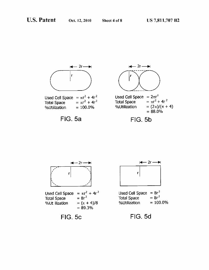
FIGS. 5(a)-5(d) are schematic drawings comparing differ ent spatial utilizations of different battery form factors includ ing the battery of this invention (FIG. 5(a)) and comparison examples typical of commercial batteries used today includ ing two 18650 cells in parallel (FIG. 5(b)), a prismatic cell containing a woundjelly roll electrode structure (FIG. 5(c)) and a prismatic cell containing a stacked electrode structure (FIG. 5(d)).
FIG. 6 is a graph showing typical charge curves of a battery of the invention and a control battery at room temperature.
FIG. 7 is a graph showing relative capacity retention during charge-discharge cycling at room temperature of a battery of the invention and two control batteries: cycling conditions: constant charge constant Voltage (CCCV) charging using 0.7 C constant charge followed by constant Voltage charge at 4.2 V and then 1 C discharge to 2.75 V.
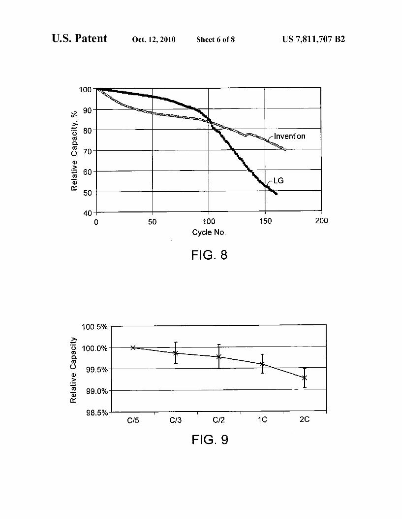
FIG. 8 is a graph showing relative capacity retention during charge-discharge cycling at 60° C. of a battery of the inven tion and a control battery under the conditions described in FIG. 7.
FIG. 9 is a graph showing the rate capability for an average and standard deviation of eight batteries of the invention and

US 7,811,707 B2 5
two control commercial 18650 batteries where the batteries are charged under the charge conditions described in FIG. 7 and discharged to 2.75 V at the rates indicated in the figure.
FIG. 10 is a graph showing the total heat of reaction of cathode mixtures of the invention, which includes a lithium cobaltate and a manganate spinel, and of the lithium cobal tate- and the manganate spinel, in DSC tests.
FIG. 11 is a graph showing the maximum heat flow during reaction of cathode mixtures of the invention, which includes a lithium cobaltate and a manganate spinel, in DSC tests.
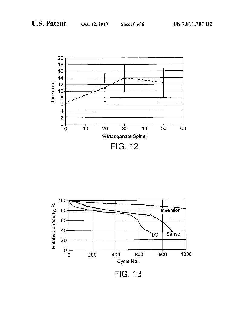
FIG. 12 is a graph showing time spent by a lithium-ion battery of the invention, which includes a cathode mixture that includes a lithium cobaltate and a manganate spinel, prior to rapid cell reaction (e.g., fire or explosion) during abuse testing.
FIG. 13 is a graph showing cyclability of a lithium-ion battery of the invention, which includes 70 wt % of LiCoO. and 30 wt % of Li Mn2O as an active cathode material, and showing cyclability of two commercially available 18650 batteries with 100 wt % of LiCoO as an active cathode material.
DETAILED DESCRIPTION OF THE INVENTION
The foregoing and other objects, features and advantages of the invention will be apparent from the following more particular description of preferred embodiments of the inven tion, as illustrated in the accompanying drawings in which like reference characters refer to the same parts throughout the different views. The drawings are not necessarily to scale, emphasis instead being placed upon illustrating the principles of the invention.
In one embodiment, the present invention relates to an active cathode material mixture that can be employed in an electrode of a lithium-ion battery that allows lithium to be reversibly intercalated and extracted. The active cathode material comprises a mixture that includes: at least one of a lithium cobaltate and a lithium nickelate; and at least one of a manganate spinel and an olivine compound. A lithium nickelate that can be used in the invention
includes at least one modifier of either the Liatom or Niatom, or both. As used herein, a “modifier” means a substituent atom that occupies a site of the Liatom or Niatom, or both, in a crystal structure of LiNiO. In one embodiment, the lithium nickelate includes only a modifier of Liatom (“Limodifier”). In another embodiment, the lithium nickelate includes only a modifier of Ni atom (“Ni modifier”). In yet another embodi ment, the lithium nickelate includes both of the Li and Ni modifiers. Examples of the Limodifier include barium (Ba), magnesium (Mg), calcium (Ca) and strontium (Sr). Examples of the Ni modifier include those modifiers for Li and in addition aluminum (Al), manganese (Mn) and boron (B). Other examples of the Nimodifier include cobalt (Co) and titanium (Ti). Preferably, the lithium nickelate is coated with LiCoO. The coating can be a gradient coating or a spot-wise coating. One particular type of a lithium nickelate that can be used
in the invention is represented by an empirical formula of LiNiMO, where 0.05<x3<1.2 and 0<z3<0.5, and M' is one or more elements selected from a group consisting of Co, Mn, Al, B, Ti, Mg, Ca and Sr. Preferably, M' is one or more elements selected from a group consisting of Mn, Al, B, Ti, Mg, Ca and Sr.
Another particular type of a lithium nickelate that can be used in the invention is represented by an empirical formula of Lia A, sNia Co...O.O., where X4 is equal to or greater than about 0.1 and equal to or less than about 1.3; x5
5
10
15
25
30
35
40
45
50
55
60
65
6 is equal to or greater than 0.0 and equal to or less than about 0.2; y4 is equal to or greater than 0.0 and equal to or less than about 0.2; Z4 is equal to or greater than 0.0 and equal to or less than about 0.2; a is greater than about 1.5 and less than about 2.1; A* is at least one member of the group consisting of barium (Ba), magnesium (Mg) and calcium (Ca); and Q is at least one member of the group consisting of aluminum (Al), manganese (Mn) and boron (B). Preferably, y4 is greater than Zero. In one preferred embodiment, X5 is equal to Zero, and Z4 is greater than 0.0 and equal to or less than about 0.2. In another embodiment, Z4 is equal to Zero, and X5 is greater than 0.0 and equal to or less than about 0.2. In yet another embodiment, X5 and Z4 are each independently greater than 0.0 and equal to or less than about 0.2. In yet another embodi ment, X5, y4 and Z4 are each independently greater than 0.0 and equal to or less than about 0.2. Various examples of lithium nickelates where X5, y4 and Z4 are each indepen dently greater than 0.0 and equal to or less than about 0.2 can be found in U.S. Pat. Nos. 6,855.461 and 6,921,609 (the entire teachings of which are incorporated herein by reference). A specific example of the lithium nickelate is
LiNios Coos AloosO2. A preferred specific example is LiCoO-coated LiNiCoos Alos.O. The spot-wise coated cathode has LiCoO not fully coated on top of a nickelate core particle, so that the higher reactivity nickelate is deactivated and hence safer. The composition of LiNios Coos Aloos.O. coated with LiCoO can naturally deviate slightly in compo sition from the 0.8:0.15:0.05 weight ratio between Ni:Co:Al. Deviation may be approximately 10-15% for the Ni, 5-10% for Co and 2-4% for Al.
Another specific example of the lithium nickelate is Lice,Mgolo NicoCool O. A preferred specific example is LiCoO-coated Lio,Mgolo NicoCool O. The spot-wise coated cathode has LiCoO not fully coated on top of a nick elate core particle, so that the higher reactivity nickelate is deactivated and hence safer. The composition of Liolo,Mgolos NiocCool O2 coated with LiCoO2 can naturally deviate slightly in composition from the 0.03:0.9:0.1 weight ratio between Mg:Ni:Co. Deviation may be approximately 2-4% for Mg, 10-15% for Ni and 5-10% for Co.
Another preferred nickelate that can be used in the present invention is Li(NiCoMn)O, which is also called “333-type nickelate.” This 333-type nickelate can be option ally coated with LiCoO as described above.
Suitable examples of lithium cobaltates that can be used in the invention include LiCoO, that is modified by at least one of modifiers of Li and Coatoms. Examples of the Limodifiers are as described above for Li for LiNiO. Examples of the Co modifiers include the modifiers for Li and aluminum (Al), manganese (Mn) and boron (B). Other examples include nickel (Ni) and titanium (Ti). Particularly, lithium cobaltates represented by an empirical formula of Li, McCoo M"O, where x6 is greater than 0.05 and less than 1.2: yo is equal to or greater than 0 and less than 0.1, Z6 is equal to or greater than 0 and less than 0.5; M' is at least one member of magnesium (Mg) and sodium (Na) and M" is at least one member of the group consisting of manganese (Mn), alumi num (Al), boron (B), titanium (Ti), magnesium (Mg), calcium (Ca) and strontium (Sr), can be used in the invention.
Another example of lithium cobaltates that can be used in the invention includes LiCoO.
It is particularly preferred that the compounds have a spherical-like morphology as this improves packing and pro duction characteristics.
Preferably, a crystal structure of each of the lithium cobal tate and lithium nickelate is independently a R-3m type space group (rhombohedral, including distorted rhombohedral).

US 7,811,707 B2 7
Alternatively, a crystal structure of the lithium nickelate can be in a monoclinic space group (e.g., P2/m or C2/m). In a R-3m type space group, the lithium ion occupies the "3a site (x=0, y=0 and Z=0) and the transition metal ion (i.e., Ni in a lithium nickelate and Co in a lithium cobaltate) occupies the “3b' site (x=0, y=0, Z=0.5). Oxygen is located in the “6a” site (x=0, y=0, Z Z0, where Z0 varies depending upon the nature of the metal ions, including modifier(s) thereof).
Olivine compounds that can be used in the invention are generally represented by a general formula LiA"MPO, where X2 is equal to or greater than 0.05, or X2 is equal to or greater than 0.0 and equal to or greater than 0.1; M is one or more elements selected from a group consisting of Fe, Mn, Co, or Mg, and A" is selected from a group consisting of Na, Mg, Ca, K, Ni, Nb. Preferably, M is Fe or Mn. More prefer ably, LiFePO or LiMnPO or both are used in the invention. In a preferred embodiment, the olivine compounds are coated with a material having high electrical conductivity, Such as carbon. In a more preferred embodiment, carbon-coated LiFePO or carbon-coated LiMnPO is used in the invention. Various examples of olivine compounds where M is Fe or Mn can be found in U.S. Pat. No. 5,910,382 (the entire teachings of which are incorporated herein by reference). The olivine compounds have typically a small change in
crystal structure upon charging/discharging, which makes the olivine compounds Superior in terms of cycle characteristic. Also, safety is generally high even when a battery is exposed to a high temperature environment. Another advantage of the olivine compounds (e.g., LiFePO and LiMnPO) is their relatively low cost.
Manganate spinel compounds have a manganese base, such as LiMn2O. While the manganate spinel compounds typically have low specific capacity (e.g., in a range of about 120 to 130 mAh/g), they have high power delivery when formulated into electrodes and are typically safe in terms of chemical reactivity at higher temperatures. Another advan tage of the manganate spinel compounds is their relatively low cost. One type of manganate spinel compounds that can be used
in the invention is represented by an empirical formula of Lili (Mn-1A,2)-2O, where A' is one or more of Mg, Al, Co, Ni and Cr; x1 and x2 are each independently equal to or greater than 0.01 and equal to or less than 0.3;y 1 and y2 are each independently equal to or greater than 0.0 and equal to or less than 0.3; Z1 is equal to or greater than 3.9 and equal to or less than 4.1. Preferably, A' includes a M." ion, such as Al", Co", Ni" and Cr", more preferably Al". The manganate spinel compounds of Lili (Mn-A2)2O. can have enhanced cyclability and power compared to those of LiMn2O4.
In some embodiments where the cathode mixtures of the invention include a manganate spinel, the manganate spinel for the invention includes a compound represented by an empirical formula of Li(Mn-A2)2O, where y1 andy2 are each independently greater than 0.0 and equal to or less than 0.3, and the other values are the same as described above.
In other embodiments where the cathode mixtures of the invention include a manganate spinel, the manganate spinel for the invention includes a compound represented by an empirical formula of Li, MnO, where x1 and z1 are each independently the same as described above.
Alternatively, the manganate spinel for the invention includes a compound represented by an empirical formula of Li,Mn2,O-7 where x7 and y7 are each independently equal to or greater than 0.0 and equal to or less than 1.0; and Z7 is equal to or greater than 3.9 and equal to or less than 4.2.
5
10
15
25
30
35
40
45
50
55
60
65
8 Specific examples of the manganate spinel that can be used
in the invention include LiMn. Alo, O, Li MnO, Li,Mn2,Oa, and their variations with Al and Mg modi fiers. Various other examples of manganate spinel compounds of the type Lili (Mn-A2)2O. can be found in U.S. Pat. Nos. 4.366,215; 5,196,270; and 5,316,877 (the entire teachings of which are incorporated herein by reference). The active cathode materials of the invention can be pre
pared by mixing two or more active cathode components described above (i.e., a lithium cobaltate, a lithium nickelate, a manganate spineland an olivine compound), preferably in a powdered form. Generally, the olivine compounds, such as LiFePO4, manganate spinel compounds, such as Lili (Mn-1A,2)-2O, and lithium nickelates, such as LiONiCo, Mn).O., have high safety. Generally, lithium cobaltates, such as LiCoO and lithium nickelates, such as Li(Ni, Col/Mn/s)O, and Li, Nila Co, Q O-type compounds have a high-energy density. General properties of Some cathode components for the cathode materials of the invention are summarized in Table 1.
TABLE 1
Typical Attributes of Active Cathode Materials of the Invention
1. Cycle Cathode Density C20 Capacity 1C Capacity Efficiency Material (g/cc) (mAh/g) (mAh/g) (%)
lithium cobaltate 5.05 150 145 96 lithium nickelate 4.8O 210 18O 92 olivine (M = Fe) 3.30 155 140 95 manganate spinel 4.2O 120 115 94
Characteristics of the cathode materials of the invention relate to capacity, cyclability, and safety. For example, the cathode materials of the invention can exhibit different capacities depending on the charge/discharge rate and other external conditions, such as electrolyte choice and electrode formulation. “Capacity' is defined herein as the number of Li ions that can reversibly be removed from the crystal structures of lithium-based materials, such as those of the invention. “Reversibility,” as defined herein, means that the structure Substantially maintains its integrity and that Li can be inter calated back to restore the initial crystal structure. In theory, this is the definition of capacity at an infinitely small rate. “Safety, as defined herein, means structural stability or struc tural integrity; if a material decomposes during cycling or is easily decomposed or causes gassing at elevated tempera tures, the material is considered unsafe, particularly if the decomposition or gassing leads to initiation of thermal run away behavior inside the cell or produces high internal pres sure. Polarization behavior adds yet another dimension to capacity and the effects of polarization behavior to perfor mance of a lithium-ion battery are determined by the interac tion between the lithium-ion cell and the control electronics of the battery pack or application device using the lithium-ion cell.
Formulation of an electrode suitable for high energy and power, and Sufficient safety, can be achieved by a specific ratio of components (i.e., a lithium cobaltate, a lithium nick elate, a manganate spinel and an olivine compound) of the active cathode materials of the invention.
In one embodiment, an active cathode material of the invention includes a lithium nickelate that includes at least one modifier of either the Li atom or Ni atom, or both. Pref erably, the lithium nickelate is represented by an empirical formula of Li, Nis,MO, described above. Alterna
US 7,811,707 B2 9
tively, the lithium nickelate is represented by an empirical formula of LiA’ sNia CoQ-O, described above. In a specific example, the lithium nickelate is represented by an empirical formula of Li, A*, sNia Co-O-O, where X5, y4 and Z4 are each independently greater than 0.0 and equal to or less than about 0.2. Specific examples of the lithium nickelate are as described above.
In a second embodiment, an active cathode material of the invention includes a lithium cobaltate represented by an empirical formula of Lic Co-M"...O., described above. Specific examples of the lithium cobaltate are as described above.
In a third embodiment, an active cathode material of the invention includes an olivine compound represented by an empirical formula of Li-2A"...MPO described above. Specific examples of the olivine compound are as described above. In a preferred embodiment, Mis iron or magnesium. In a preferred embodiment, the olivine compound is coated with carbon.
In a fourth embodiment, an active cathode material of the invention includes a lithium cobaltate, such as LiCoO, and a manganate spinel. The lithium cobaltate and manganate spinel, including specific examples thereof, are as described above. Preferably, the lithium cobaltate, and manganate spinel are in a weight ratio of lithium cobaltate:manganate spinel between about 0.8:0.2 to about 0.4:0.6. In one example of the fourth embodiment, the manganate spinel is repre sented by Lil (Mn-A2)2O. In another example of the fourth embodiment, the manganate spinel is represented by Li,Mn2-, O-7, preferably Li,Mn2O-7 (e.g., LiMn2O). In yet another example of the fourth embodi ment, the manganate spinel is represented by Li Mn2O. In a fifth embodiment, an active cathode material of the inven tion includes a lithium nickelate and a manganate spinel represented by Lili (Mn-A',2)-2O. described above. The lithium nickelate and manganate spinel, including spe cific examples thereof, areas described above. Preferably, the lithium nickelate and manganate spinel are in a weight ratio of lithium nickelate:manganate spinel between about 0.9:0.1 to about 0.3:0.7. In one example of the fifth embodiment, the lithium nickelate is Li(NiaCola Mnia)O2. LiNiosCooos.AloosC or Liolo,Mgolos NiocCool O. Prefer ably, the lithium nickelate is LiCoO-coated, LiNiosCoolis AlolosQ2 or Lio97Mgolos NiogCooloC2. When LiCoO-coated, LiNios Cools.Aloos C2 O Liolo,Mgolos NiocCool O2 is used, the lithium nickelate and manganate spinel are preferably in a weight ratio of lithium nickelate-to-manganate spinel between about 0.9:0.1 to about 0.3:0.7. When Li(NiCo,Mn)O, is used, the lithium nickelate and manganate spinel are preferably in a weight ratio of lithium nickelate:manganate spinel between about 0.7:0.3 to about 0.3:0.7.
In a sixth embodiment, an active cathode material of the invention includes at least one lithium nickelate selected from the group consisting of Li(NiCoMn)O and LiCoO coated LiNios Coos AloosO, and a manganate spinel repre sented by Li,Mn2-, O-7, preferably Li Mn2O4. Such as LiMnO. Preferably, the lithium nickelate and manganate spinel are in a weight ratio of lithium nickelate:manganate spinel between about 0.9:0.1 to about 0.3:0.7. When LiONiCoMn)O is used, the lithium nickelate and manganate spinel are in a weight ratio of lithium nickelate: manganate spinel between about 0.9:0.1 to about 0.5:0.5.
In a seventh embodiment, the active cathode material of the invention includes a lithium cobaltate. Such as LiCoO, a manganate spinel and a lithium nickelate. The lithium cobal tate, manganate spinel and lithium nickelate, including spe
10
15
25
30
35
40
45
50
55
60
65
10 cific examples thereof, areas described above. Preferably, the lithium cobaltate, manganate spineland lithium nickelate are in a weight ratio of lithium cobaltate:manganate spinel: lithium nickelate between about 0.05 and about 0.8: between about 0.05 and about 0.7 (e.g., between about 0.05 and about 0.3, or between about 0.3 and about 0.7): between about 0.05 and about 0.9 (e.g., between about 0.4 and about 0.9, or between about 0.05 and about 0.8). In one example, the lithium nickelate is represented by Li, A* is Ni---a CoQ.O. In a second example, the lithium nickelate is represented by Li, Ni, M.O., more preferably LiNios Coos AloosO2 that is gradient- or spot-wise coated with LiCoO. In a third example, the lithium nickelate is LiONiCoMn)O. In a fourth example, the lithium nickelate includes at least one modifier of both the Li and Ni
atoms, such as LiA’ sNia Co-Q-O, where X5, y4 and Z4 are each independently greater than 0.0 and equal to or less than about 0.2, and the manganate spinel is represented by Lili (Mn-1A,2)-2O. Preferably, when Li,4A'sNi(1-4-4Co,4Q-4O, and Lili (Mn A',2)-2O. are used, the lithium cobaltate, manganate spinel and lithium nickelate are in a weight ratio of lithium cobal tate:manganate spinel: lithium nickelate between about 0.05 and about 0.30: between about 0.05 and about 0.30: between about 0.4 and about 0.9. In a fifth example, the lithium nick elate is Li(NiCoMn)O or optionally LiCoO-coated LiNios Coos AloosO2, and the manganate spinel is repre sented by Li,(Mn-A',2)-2O. In this fifth example, when Li(NiCoMn)O is used, Li(NiCo, Mn.) O2, Lili (Mn-1A2)-2O, and lithium cobaltate are in a weight ratio of Li(Ni, Cola Mnia)O:Li,(Mn A',2)-2O: lithium cobaltate between about 0.05 and about 0.8; between about 0.3 and about 0.7: between about 0.05 and about 0.8.
In an eighth embodiment, an active cathode material of the invention includes two or more lithium nickelates and a man ganate spinel. The lithium nickelates and manganate spinel, including specific examples thereof, are as described above. Preferably, lithium nickelates and manganate spinel are in a weight ratio of lithium nickelates: manganate spinel between about 0.05 and about 0.8: between about 0.05 and about 0.9. Preferably, the manganate spinel is represented by Li (Mn-1A,2)-2O. In one example, the lithium nickelates include a lithium nickelate represented by Lia As Nia Co-O-O. In another example, the lithium nick elates includes a lithium nickelate represented by LiNis, MO. Alternatively, the lithium nickelates includes a lithium nickelate including at least one modifier of both the Li and Ni atoms, such as Li, A*, sNia a CoQ-O, where X5, y4 and Z4 are each independently greater than 0.0 and equal to or less than about 0.2. In a specific example, the lithium nickelates include LiONiCo,Mn)O and a lithium nickelate represented by Lia A', sNia Co, Q-O. In another specific example, the lithium nickelates include Li(NiCo, Mn.) O; and a lithium nickelate that includes at least one modifier of both the Li and Ni atoms, such as Li, A*sNia a CoQ-O, where X5, y4 and Z4 are each independently greater than 0.0 and equal to or less than about 0.2. In yet another specific example, the lithium nickelates include LiONiCoMn)O and a lithium nickelate represented by Li,4A's Ni----4Co,4Q-4O and the manganate spinel is represented by Lili,(Mn-1A,2)-2O. In this specific example, the lithium nickelates and manganate spinel are in a weight ratio of Li(Ni/CoaMn/s)O3. Li, A* is Ni---a
US 7,811,707 B2 11
CoQ.O., Lili,(Mn-1A,2)-2O, between about 0.05 and about 0.8: between about 0.05 and about 0.7: between about 0.05 and about 0.9.
In a ninth embodiment, an active cathode material of the invention includes a lithium cobaltate. Such as LiCoO, and an olivine compound represented by Li-2A"...MPO, described above, preferably coated with carbon. The lithium cobaltate and olivine compound, including specific examples thereof, areas described above. Preferably, the lithium cobal tate and olivine compound are in a weight ratio of lithium cobaltate:olivine compound between about 0.9:0.1 to about 0.3:0.7. In one example, the olivine compound is represented by Li-2A"2MPO, where M is iron or manganese, such as LiFePO and LiMnPO. In this example, preferably, the lithium cobaltate and olivine compound are in a weight ratio of lithium cobaltate:olivine compound between about 0.8:0.2 to about 0.4:0.6.
In a tenth embodiment, an active cathode material of the invention includes a lithium nickelate, and an olivine com pound represented by Li-2A"2MPO described above, preferably coated with carbon. The lithium nickelate and olivine compound, including specific examples thereof, areas described above. Preferably, the lithium nickelate and olivine compound are in a weight ratio of lithium nickelate:olivine compound between about 0.9:0.1 to about 0.3:0.7. In one example, the olivine compound is represented by Li-2, A"MPO where M is iron or manganese, such as LiFePO and LiMnPO. In a second example, the lithium nickelates include a lithium nickelate represented by LiA’s Nia Co-O-O. In a third example, the lithium nick elates includes a lithium nickelate represented by Li Ni-M' O. Alternatively, the lithium nickelates includes a lithium nickelate including at least one modifier of both the Li and Ni atoms, such as Li, A* is Nila Co-O-O, where X5, y4 and Z4 are each independently greater than 0.0 and equal to or less than about 0.2. In a specific example, the lithium nickelate is Li(NiCoMn)O and the olivine compound is represented by Li-2A"2MPO, where M is iron or manganese. Preferably, in the second example, the lithium nickelate and olivine compound are in a weight ratio of lithium nickelate:olivine compound between about 0.9:0.1 to about 0.5:0.5. In a second specific example, the lithium nickelate is represented by Li, A*, sNia Co-Q-O. preferably Li, A* is Ni-CoQ-O, where X5, y4 and Z4 are each independently greater than 0.0 and equal to or less than about 0.2, and the olivine compound is represented by LiA", MPO, where M is iron or manganese. In a third specific example, the lithium nickelate is LiNiosCools AlolosQ2. preferably LiCoO-coated LiNio sCoos AloosC2, and the olivine compound is repre sented by Li-2A"...MPO, where M is iron or manganese. Preferably, in the third specific example, the lithium nickelate and olivine compound are in a weight ratio of lithium nick elate:olivine compound between about 0.9:0.1 to about 0.3: 0.7.
In an eleventh embodiment, an active cathode material of the invention includes two or more lithium nickelates, and an olivine compound, preferably an olivine compound repre sented by Li-2A"...MPO, where M is iron or manganese. The lithium nickelates and olivine compound, including spe cific examples thereof, areas described above. Preferably, the olivine compound is coated with carbon. In this embodiment, the lithium nickelates and olivine compound are in a weight ratio of lithium nickelates: olivine compound between about 0.05 and about 0.9: between about 0.05 and 0.9. In one example, the lithium nickelates include a lithium nickelate represented by Li, A*, sNia Co...Q.-O. In another
5
10
15
25
30
35
40
45
50
55
60
65
12 example, the lithium nickelates includes a lithium nickelate represented by Li, Nis, MO. Alternatively, the lithium nickelates includes a lithium nickelate including at least one modifier of both the Li and Ni atoms, such as LiA’s Nia Co, Q-O, where X5, y4 and Z4 are each indepen dently greater than 0.0 and equal to or less than about 0.2. In a specific example, the lithium nickelate is represented by an empirical formula of Li, A*, sNia Co-Q-O, where X5, y4 and Z4 are each independently greater than 0.0 and equal to or less than about 0.2. In one specific example, the olivine compound is represented by Li-2A",2MPO, where M is iron or manganese, such as LiFePO and LiMnPO, and the lithium nickelates include Li(NiCoMn)O and a lithium nickelate including at least one modifier of both the Li and Niatoms, such as LiA’ sNia Co..Q.O., where X5, y4 and Z4 are each independently greater than 0.0 and equal to or less than about 0.2. In this example, the lithium nickelates and olivine compound are preferably in a weight ratio of Li(NiCoMn)O: lithium nickelate: olivine compound between about 0.05 and about 0.8: between about 0.05 and about 0.7: between about 0.05 and about 0.9.
In a twelfth embodiment, an active cathode material of the invention includes a lithium nickelate, a lithium cobaltate, Such as LiCoO, and an olivine compound represented by Li-A"...MPO described above. The lithium nickelate, lithium cobaltate and olivine compound, including specific examples thereof, are as described above. In this embodi ment, the lithium nickelate, lithium cobaltate and olivine compound are preferably in a weight ratio of lithium cobal tate:olivine compound:lithium nickelate between about 0.05 and about 0.8: between about 0.05 and about 0.7: between about 0.05 and about 0.9. In one example, the lithium nick elates include a lithium nickelate represented by LiAs Nia Co, Q-O. In another example, the lithium nick elates includes a lithium nickelate represented by LisNils M.O.. Alternatively, the lithium nickelates includes a lithium nickelate including at least one modifier of both the Li and Ni atoms, such as Li, A*, sNia a CoQ-O, where X5, y4 and Z4 are each independently greater than 0.0 and equal to or less than about 0.2. In one specific example, the lithium nickelate is represented by Li,4A'sNi(1-4-4Co,4Q-4O. preferably Lia A's Nia Co, Q-O, where X5, y4 and Z4 are each indepen dently greater than 0.0 and equal to or less than about 0.2, and the olivine compound is represented by Li-2A",2MPO, where M is iron or manganese. In this specific example, the lithium nickelate, lithium cobaltate and olivine compound are preferably in a weight ratio of lithium cobaltate:olivine com pound: lithium nickelate between about 0.05 and about 0.30: between about 0.05 and about 0.30: between about 0.4 and about 0.9. In a second specific example, the lithium nickelate is Li(NiCoMn)O, and the olivine compound is rep resented by Li-2A"...MPO, where M is iron or manga nese. In the second specific example, preferably the lithium nickelate, lithium cobaltate and olivine compound are in a weight ratio of lithium nickelate:olivine: lithium cobaltate between about 0.05-0.8: about 0.3-0.7: about 0.05-0.8. In a third specific example, the lithium nickelate is LiNiosCools AlolosQ2. preferably LiCoO-coated LiNios Coos AloosO2, and the olivine compound is repre sented by Li-2A"MPO, where M is iron or manganese.
In a thirteenth embodiment, an active cathode material of the invention includes a manganate spinel, an olivine com pound, preferably an olivine compound represented by Li-2A"...MPO, where M is iron or manganese, and a lithium nickelate. The manganate spinel, olivine compound and lithium nickelate, including specific examples thereof,

US 7,811,707 B2 13
are as described above. In this embodiment, manganate spinel, olivine compound and lithium nickelate are preferably in a weight ratio of manganate spinel:olivine: lithium nick elate between about 0.05-0.9: about 0.05-0.9: about 0.05-0.9. In one example, the manganate spinel is represented by Lic)(Mn-1A2)2-2O. In another example, the manga nate spinel is represented by Li,Mn., O-7. In yet another example, the manganate spinel is represented by Li MnO, such as LiMn2O. In one specific example, the manganate spinel is represented by Lili (Mn A',2)-2O, and the lithium nickelate includes at least one modifier of both the Li and Ni atoms, such as a lithium nickelate represented by Li, A*, sNia CoQ-O, where X5, y4 and Z4 are each independently greater than 0.0 and equal to or less than about 0.2. In a second specific example, the manganate spinel is represented by Lil (Mn-A,2)-2O, and the lithium nickelate is represented by LisNi--M.O. preferably LiNiosCools.AloosC). more preferably LiCoO-coated LiNios Coos Alos.O. In a third specific example, the manganate spinel is represented by Lili,(Mn-A'). O. and the lithium nickelate is LiONiCoMn)O. In a fourth specific example, the manganate is represented by Li,Mn2O, or LiMnO, or is a variation thereof modified with Al and Mg, and the lithium nickelate is selected from the group consisting of Li(NiCo,Mn)O, and LiCoO-coated LiNiosCoolis AloosC2.
In a fourteenth embodiment, an active cathode material of the invention includes two or more lithium nickelates as described above. In one example, the active cathode material includes Li(NiCoMn)O. In a specific example, the active cathode material includes Li(NiCoMn)O and a lithium nickelate including at least one modifier of both the Li and Ni atoms, such as a lithium nickelate represented by LiA’ sNia Co, Q-O, where X5, y4 and Z4 are each independently greater than 0.0 and equal to or less than about 0.2. Preferably, in this example, the lithium nickelates are in a weight ratio of Li(Ni, Cois Mn/s).O.LiA’ sNia a CoQ. O, between about 0.7:0.3 to about 0.3:0.7. In another specific example, the active cathode material includes Li(NiaCola Mn/s)Q2 and LiNiosCoolis AloosC2, more preferably LiCoO-coated LiNiCoos Alos.O. Prefer ably, in this example, the lithium nickelates are in a weight ratio of Li(NiaCola Mn/s)O2:LiNios Coos AloosO2 between about 0.8:0.2 to about 0.2:0.8.
In a fifteenth embodiment, an active cathode material of the invention includes a lithium cobaltate and a manganate spinel, as described above. In a preferred embodiment, the manganate spinel is represented by an empirical formula of Lili (Mn-1A,2)-2O, wherein the variables are as described above. Examples of the lithium cobaltate, includ ing preferred values, areas described above. In this embodi ment, the lithium cobaltate and the manganate spinel are in a weight ratio of lithium cobaltate:manganate spinel between about 0.95:0.05 to about 0.55:0.45, preferably between about 0.9:0.1 to about 0.6:0.4, more preferably between about 0.8: 0.2 to about 0.6:0.4, even more preferably between about 0.75:0.25 to about 0.65:0.45, such as about 0.7:0.3.
In the fifteenth embodiment, preferably, the lithium cobal tate is represented by an empirical formula of LiMo Co-M"...O., where: x6 is greater than 0.05 and less than 1.2: yo is greater than or equal to 0 and less than 0.1; Z6 is equal to or greater than 0 and less than 0.5; M' is at least one of magnesium (Mg) and Sodium (Na) and M" is at least one member of the group consisting of manganese, aluminum, boron, titanium, magnesium, calcium and strontium. In one specific embodiment, the lithium cobaltate is LiCoO doped
10
15
25
30
35
40
45
50
55
60
65
14 with Mg and/or coated with a refractive oxide or phosphate, such as ZrO or Al(PO). In another specific embodiment, the lithium cobaltate is LiCoO with no modifiers.
In the fifteenth embodiment, preferably, the manganate spinel does not have the A' modifier, i.e., y2 is equal to Zero in the formula of Lili,(Mn-1A,2)-2O. In a specific embodiment, the manganate spinel includes a compound rep resented by an empirical formula of Li,Mn2O, where the variables are as described above. In another specific embodiment, the manganate spinel includes a compound rep resented by an empirical formula of Li, Mn., O-7 where the variables are as described above, preferably Li, Mn2,Oa. Alternatively, the manganate spinel includes a compound represented by an empirical formula of Li (Mn-1A,2)-2O, where y1 and y2 are each indepen dently greater than 0.0 and equal to or less than 0.3, and other values are the same as described above.
In a even more preferred embodiment where the active cathode material includes a lithium cobaltate and a mangan ate spinel, the lithium cobaltate is LiCoO with no modifiers and the manganate spinel does not have the A modifier.
Another aspect of the present invention is directed to a lithium-ion battery that employs the active cathode materials of the invention described above. Preferably, the battery has a greater than about 2.2 Ah/cell capacity. More preferably, the battery has a greater than about 3.0 Ah/cell capacity. Such as equal to or greater than about 3.3 Ah/cell; equal to or greater than about 3.5 Ah/cell; equal to or greater than about 3.8 Ah/cell; equal to or greater than about 4.0 Ah/cell; equal to or greater than about 4.2 Ah/cell; between about 3.0 Ah/cell and about 6 Ah/cell; between about 3.3 Ah/cell and about 6 Ah/cell; between about 3.3 Ah/cell and about 5 Ah/cell; between about 3.5Ah/celland about 5Ah/cell; between about 3.8 Ah/cell and about 5 Ah/cell; and between about 4.0 Ah/cell and about 5 Ah/cell.
In one embodiment, the batteries of the invention include an active cathode material including a mixture that includes: at least one of a lithium cobaltate and a lithium nickelate; and at least one of a manganate spinel represented by an empirical formula of Lili (Mn-A',2)-2O. described above and an olivine compound represented by an empirical formula of Li-A"...MPO described above. In another embodiment, the batteries of the invention include an active cathode mate rial including a mixture that includes: at least one of a lithium cobaltate and a lithium nickelate selected from the group consisting of LiCoO2-coated LiNio sCoos AloosC2, and LiONiCo,Mn)O; and a manganate spinel having an empirical formula of Liz Mn., O-7 described above. In yet another embodiment, the batteries of the invention include an active cathode material including a mixture that includes: a lithium nickelate selected from the group consisting of LiCoO-coated LiNiosCools Aloloso2. and LiONiaCola Mnis)O2, and a manganate spinel having an empirical formula of Liz Mn.,.O., described above. The batteries each independently have a capacity as described above, preferably greater than about 3.0 Ah/cell.
In a preferred embodiment, cell building for the batteries of the invention utilize a larger format in terms of Ah/cell than is currently used in the industry such as in the case for 18650 cells.
FIG. 1 shows a cylindrical shape lithium-ion battery (10), which includes a positive electrode (1), coated onto an alu minum foil, a negative electrode (2), coated onto a copper foil, a separator positioned between the positive and negative electrodes (3), a can containing the wound components (4), an electrically insulated (5a) (from can) top that is crimped onto the can (5b) (top may contain a current-interrupt-device CID,

US 7,811,707 B2 15
and a vent (5c)), nickel lead that is electrically connecting the anode with the top, and an aluminum lead that is electrically connecting the cathode with the can (6). APTC switch (7) can be located inside or outside the can. Insulators are also located at the top (8) and the bottom (9) of the can that keep foils from 5 touching each other and insulates foil ends from can.
The negative active material (anode) can include any mate rial allowing lithium to be inserted in or removed from the material. Examples of Such materials include carbonaceous materials, for example, non-graphitic carbon, artificial car- 10 bon, artificial graphite, natural graphite, pyrolytic carbons, cokes such as pitch coke, needle coke, petroleum coke, graph ite, vitreous carbons, or a heat treated organic polymer com pound obtained by carbonizing phenol resins, furan resins, or similar, carbon fibers, and activated carbon. Further, metallic 15 lithium, lithium alloys, and an alloy or compound thereof are usable as the negative active materials. In particular, the metal element or semiconductor element allowed to form an alloy or compound with lithium may be a group IV metal element or semiconductor element, such as but not limited to, silicon 20 or tin. In particular amorphous tin, that is doped with a tran sition metal. Such as cobalt or iron/nickel, is a metal that has high promise for anode material in these type batteries. Oxides allowing lithium to be inserted in or removed from the oxide at a relatively low potential. Such as iron oxide, ruthe- 25 nium oxide, molybdenum oxide, tungsten oxide, titanium oxide, and tin oxide, and nitrides can be similarly usable as the negative active materials.
The positive electrode of the batteries or cells of the inven tion include the active cathode materials of the invention 30 described above. In particular, the batteries of the invention employ the active cathode materials including two or more advantages of high specific capacity of the lithium nickelates (e.g., Li(NiaCo?s Mn/s)O2 or LiNiosCoolis AloosC2) or lithium cobaltates (e.g., LiCoO); relatively high safety of the 35 olivine compounds (e.g., LiFePO) or manganate spinels (e.g., Li MnO, or LiMn2O). When the active cathode materials of the invention are used in a positive electrode structure for use in the lithium batteries of the invention, the resulting batteries are sufficiently safe and have high capacity 40 in terms of Wh/kg and/or Wh/L. The cells of the invention typically have a form factor that is larger, both in terms of absolute volume and Ah/cell, compared to currently available 18650 cells (i.e., 183665 form factor). The increased cell size and capacity are made possible at least partly by the relatively 45 higher safety of the mixed cathode. The cells of the invention for lithium batteries can have safer properties than corre sponding cells utilizing solely LiCoO as the cathode mate rial, although the cells have similar or higher capacities.
Since each one of the cathode components in the mixture 50 has unique chemistry it is particularly important to have an electrolyte that has additives suitable for SEI formation of each chemical. For instance, a suitable electrolyte for batter ies having cathodes containing manganate spineland lithium cobaltate and anodes containing graphite may contain addi- 55 tives of LiBOB (lithium bis(oxalato)borate), PS (propylene sulfite), and VC (vinyl carbonate), which are suitable for these types of compounds.
Examples of the non-aqueous electrolytes include a non aqueous electrolytic solution prepared by dissolving an elec- 60 trolyte salt in a non-aqueous solvent, a solid electrolyte (inor ganic electrolyte or polymer electrolyte containing an electrolyte salt), and a solidor gel-like electrolyte prepared by mixing or dissolving an electrolyte in a polymer compound or the like. 65
The non-aqueous electrolytic Solution is prepared by dis Solving a salt in an organic solvent. The organic solvent can
16 include any suitable type that has been generally used for batteries of this type. Examples of Such organic solvents include propylene carbonate, ethylene carbonate, diethyl car bonate, dimethyl carbonate, 1,2-dimethoxyethane, 1,2-di ethoxyethane, Y-butyrolactone, tetrahydrofuran, 2-methyl tetrahydrofuran, 1.3-dioxolane, 4-methyl-1,3-dioxolane, diethyl ether, sulfolane, methylsulfolane, acetonitrile, propi onitrile, anisole, acetate, butyrate, propionate and the like. It is preferred to use cyclic carbonates Such as propylene car bonate, or chain carbonates Such as dimethyl carbonate and diethyl carbonate. These organic solvents can be used singly or in a combination of two types or more.
Additives or stabilizers may also be present in the electro lyte, such as VC (vinyl carbonate), VEC (vinyl ethylene car bonate), EA (ethylene acetate), TPP (triphenylphosphate), phosphaZenes, LiBOB (lithium bis(oxalato)borate), LiBETI, LiTFSI, BP (biphenyl), PS (propylene sulfite), ES (ethylene sulfite), AMC (allylmethylcarbonate), and APV (divinyladi pate). These additives are used as anode and cathode stabiliz ers or flame retardants, which may make a battery have higher performance in terms of formation, cycle efficiency, safety and life. Since each one of the cathode components in the mixture has unique chemistries it is particularly important to have an electrolyte that has additives suitable for SEI forma tion of each chemical. For instance a suitable electrolyte for a Li-ion battery having a spinel and cobaltate mixed cathode and a graphite anode may contain additives of LiBOB, PS and VC stabilizers, which respectively are suitable for the indi vidual compounds SEI formations. The Solid electrolyte can include an inorganic electrolyte, a
polymer electrolyte and the like insofar as the material has lithium-ion conductivity. The inorganic electrolyte can include, for example, lithium nitride, lithium iodide and the like. The polymer electrolyte is composed of an electrolyte salt and a polymer compound in which the electrolyte salt is dissolved. Examples of the polymer compounds used for the polymer electrolyte include ether-based polymers such as polyethylene oxide and cross-linked polyethylene oxide, polymethacrylate ester-based polymers, acrylate-based poly mers and the like. These polymers may be used singly, or in the form of a mixture or a copolymer of two kinds or more. A matrix of the gel electrolyte may be any polymer insofar
as the polymer is gelated by absorbing the above-described non-aqueous electrolytic solution. Examples of the polymers used for the gel electrolyte include fluorocarbon polymers such as polyvinylidene fluoride (PVDF), polyvinylidene-co hexafluoropropylene (PVDF-HFP) and the like.
Examples of the polymers used for the gel electrolyte also include polyacrylonitrile and a copolymer of polyacryloni trile. Examples of monomers (vinyl based monomers) used for copolymerization include vinyl acetate, methyl methacry late, butyl methacylate, methyl acrylate, butyl acrylate, ita conic acid, hydrogenated methyl acrylate, hydrogenated ethyl acrylate, acrylamide, vinyl chloride, vinylidene fluo ride, and vinylidene chloride. Examples of the polymers used for the gel electrolyte further include acrylonitrile-butadiene copolymer rubber, acrylonitrile-butadiene-styrene copoly mer resin, acrylonitrile-chlorinated polyethylene-propylene diene-styrene copolymer resin, acrylonitrile-vinyl chloride copolymer resin, acrylonitrile-methacylate resin, and acry lonitrile-acrylate copolymer resin.
Examples of the polymers used for the gel electrolyte include ether based polymers such as polyethylene oxide, copolymer of polyethylene oxide, and cross-linked polyeth ylene oxide. Examples of monomers used for copolymeriza tion include polypropylene oxide, methyl methacrylate, butyl methacylate, methyl acrylate, butyl acrylate.
US 7,811,707 B2 17
In particular, from the viewpoint of oxidation-reduction stability, a fluorocarbon polymer is preferably used for the matrix of the gel electrolyte. The electrolyte salt used in the electrolyte may be any
electrolyte salt suitable for batteries of this type. Examples of the electrolyte salts include LiClO, LiAsF LiPF, LiBF, LiB(CH), LiB(CO), CHSO, Li, CFSO.Li, LiCl, LiBr and the like.
Referring back to FIG. 1, in one embodiment of the inven tion, the separator 3 separates the positive electrode 1 from the negative electrode 2. The separator 3 can include any film-like material having been generally used for forming separators of non-aqueous electrolyte secondary batteries of this type, for example, a microporous polymer film made from polypropylene, polyethylene, or a layered combination of the two. In addition, if a solid electrolyte or gel electrolyte is used as the electrolyte of the battery 10, the separator 3 does not necessarily need to be provided. A microporous separator made of glass fiber or cellulose material can in certain cases also be used. Separator thickness is typically between 9 and 25um.
Positive electrode 2 is typically produced by mixing the cathode material at about 94 wt % together with about 3 wt % of a conductive agent (e.g. acetylene black), and about 3 wt % of a binder (e.g., PVDF). The mix is dispersed in a solvent (e.g., N-methyl-2-pyrrolidone (NMP)), in order to prepare a slurry. This slurry is then applied to both surfaces of an aluminum current collector foil, which typically has a thick ness of about 20um, and dried at about 100-150°C. The dried electrode is then calendared by a roll press, to obtain a com pressed positive electrode. The negative electrode is typically prepared by mixing
about 93 wt % of graphite as a negative active material, about 3 wt % of conductive carbon (e.g. acetylene black), and about 4 wt % of a binder (e.g. PVDF). The negative electrode is then prepared from this mix in a process similar to that described above for positive electrode except that a copper current collector foil, typically of 10-15 um thickness, is used. The negative and positive electrodes and a separator
formed of a polymer film (e.g., polyethylene) with micro pores, of thickness about 25 um, are laminated and spirally wound to produce a spiral type electrode element. Preferably this roll has an oblong shape. One or more positive lead current carrying tabs are
attached to the positive current collector and then welded to the battery top. A vent is also available, for example, at the top of the battery. A negative lead, made of nickel metal, connects the negative current collector to the bottom of the battery can. An electrolyte containing for instance PC, EC, DMC, DEC
solvents with 1M LiPF and suitable additives at 0.5-3 wt.% each, such as VC, LiBOB, PF, LiTFSI, BP, is vacuum filled in the battery can 4 having the spirally wound jelly roll', and the battery is then sealed via an insulating seal gasket 8. A safety valve 5c, current interrupt device, and a PTC device may also be present at the battery top to enhance safety. A cylindrical non-aqueous electrolyte lithium-ion secondary battery having an outer diameter of 18 mm and a height of 65 mm as shown in FIG. 1 is typical of lithium-ion cells used in the industry.
For a cell having an oblong shape as shown in FIG. 2, a similar method as described above for a cylindrical cell of the invention can be used except that the electrodes are prepared and wound to form a cell having an oblong shape, for example, with a thickness of about 17 mm or about 18 mm, a width of about 44 mm or about 36 mm, a height of about 64 mm or about 65 mm. In some specific embodiments, the cell (or battery) has a thickness of about 17 mm, a width of about
5
10
15
25
30
35
40
45
50
55
60
65
18 44 mm and a height of about 64mm; a thickness of about 18 mm, a width of about 36 mm and a height of about 65 mm; or a thickness of about 18 mm, a width of about 27 mm and a height of about 65 mm. The cells or batteries of the invention can be cylindrical or
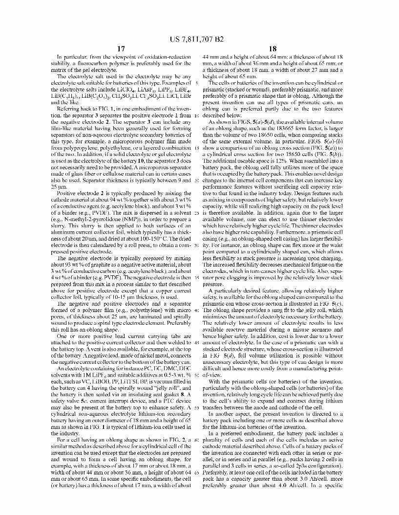
prismatic (stacked or wound), preferably prismatic, and more preferably of a prismatic shape that is oblong. Although the present invention can use all types of prismatic cans, an oblong can is preferred partly due to the two features described below. As shown in FIGS. 5(a)-5(d), the available internal volume
of an oblong shape, such as the 183665 form factor, is larger than the volume of two 18650 cells, when comparing stacks of the same external volume. In particular, FIGS. 5(a)-(b) show a comparison of an oblong cross section (FIG. 5(a)) to a cylindrical cross section for two 18650 cells (FIG. 5(b)). The additional useable space is 12%. When assembled into a battery pack, the oblong cell fully utilizes more of the space that is occupied by the battery pack. This enables novel design changes to the internal cell components that can increase key performance features without sacrificing cell capacity rela tive to that found in the industry today. Design features such as mixing in components of higher safety, but relatively lower capacity, while still realizing high capacity on the pack level is therefore available. In addition, again due to the larger available Volume, one can elect to use thinner electrodes which have relatively higher cycle life. The thinner electrodes also have higher rate capability. Furthermore, a prismatic cell casing (e.g., an oblong-shaped cell casing) has larger flexibil ity. For instance, an oblong shape can flex more at the waist point compared to a cylindrically shaped can, which allows less flexibility as stack pressure is increasing upon charging. The increased flexibility decreases mechanical fatigue on the electrodes, which in turn causes higher cycle life. Also, sepa rator pore clogging is improved by the relatively lower stack pressure. A particularly desired feature, allowing relatively higher
safety, is available for the oblong shaped can compared to the prismatic can whose cross-section is illustrated in FIG. 5(c). The oblong shape provides a snug fit to the jelly roll, which minimizes the amount of electrolyte necessary for the battery. The relatively lower amount of electrolyte results in less available reactive material during a misuse scenario and hence higher safety. In addition, cost is lower due to a lower amount of electrolyte. In the case of a prismatic can with a stacked electrode structure, whose cross-section is illustrated in FIG. 5(d), full volume utilization is possible without unnecessary electrolyte, but this type of can design is more difficult and hence more costly from a manufacturing point of-view.
With the prismatic cells (or batteries) of the invention, particularly with the oblong-shaped cells (or batteries) of the invention, relatively long cycle life can beachieved partly due to the cell’s ability to expand and contract during lithium transfers between the anode and cathode of the cell.
In another aspect, the present invention is directed to a battery pack including one or more cells as described above for the lithium-ion batteries of the invention.
In a preferred embodiment, the battery pack includes a plurality of cells and each of the cells includes an active cathode material described above. Cells of a battery packs of the invention are connected with each other in series or par allel, or in series and in parallel (e.g., packs having 2 cells in parallel and 3 cells in series, a so-called 2p3s configuration). Preferably, at least one cell of the cells included in the battery pack has a capacity greater than about 3.0 Ah/cell, more preferably greater than about 4.0 Ah/cell. In a specific

US 7,811,707 B2 19
embodiment, each cell of the battery pack of the invention includes an active cathode material including a mixture that includes: at least one of a lithium cobaltate and a lithium nickelate, as described above; and at least one of a manganate spinel represented by an empirical formula of Li (Mn-A,2)-2O. described above and an olivine com pound represented by an empirical formula of Li-2, A"MPO described above. In another specific embodiment, each cell of the battery pack includes a cathode mixture that includes: at least one of a lithium cobaltate and a lithium nickelate selected from the group consisting of LiCoO coated LiNios Coos AloosO2, and Li(NiaCo/Mn/s)O2: and a manganate spinel having an empirical formula of Liz Mn.,.O., as described above. In this specific embodiment, at least one cell of the battery pack has a capac ity greater than about 3.0 Ah/cell. In yet another specific embodiment, each cell of the battery pack includes a cathode mixture that includes: a lithium nickelate selected from the group consisting of LiCoO2-coated LiNiosCoos AloosC2. and Li(NiaCo?sMinis)O2; and a manganate spinel having an empirical formula of Liz Mn., O-7 as described above. In yet another specific embodiment, each cell of the battery pack includes a cathode mixture that includes a lithium cobaltate as described above and a manganate spinel a manganate spinel represented by an empirical formula of Lili (Mn-1A,2)-2O. described above. The lithium cobaltate and the manganate spinel are in a weight ratio of lithium cobaltate:manganate spinel between about 0.95:0.05 to about 0.55:0.45.
In a more preferred embodiment, the battery pack includes a plurality of cells, and the cells of a battery pack of the invention are connected only in series and no cells are con nected in parallel. Such a configuration is demonstrated sche matically in FIG.3 and FIG. 4. The non-parallel feature of the packallows less expensive individual control and monitoring of each cell in the pack, without having to incorporate extra circuitry for detection of individual cell parameters for cells connected in parallel, which is costly and cumbersome due to incorporation of extra algorithms in Software and probe ter minals.
FIG. 3 shows one embodiment of the invention showing three cells of the invention connected in series. These cells, due to their safer performance characteristics, can be made larger compared to cells employing LiCoO as the choice of cathode active material. This allows connecting cells into packs, having fewer cells connected in parallel.
FIG. 4 shows a top, see-through view of battery pack 30 of the invention where three cells 32 of the invention are con nected in series with each other.
In one specific embodiment, the battery packs of the inven tion have a 2p3s configuration where cells are assembled in packs having 2 cells in parallel and 3 cells in series, as can be seen in the conventional 18650 type cells typically used for laptop markets currently. In other embodiments, the battery packs of the invention have 3 S or 4 S configurations, taking advantage of the larger cell capacity enabled by the invention to simplify, and therefore lower cost and improve safety, the resulting battery pack.
Preferably, the cells included in the battery pack have oblong-shaped can 20 as shown generally in FIG. 2. The preference for this shape is illustrated in FIG. 5 and includes full volume utilization, no unnecessary electrolyte inside the cell can, and relative ease of manufacturing. The capacity of the cells in the battery packis typically equal to or greater than about 3.3 Ah. The internal impedance of the cells is preferably less than about 50 milliohms, more preferably less than 30 milliohms.
10
15
25
30
35
40
45
50
55
60
65
20 A new battery design of the invention described above can
use a larger cell sizes and can potentially replace two parallel 18650 cells (2p block). An advantage of using this configu ration is that control electronics can monitor only one cell in the block instead of two, which is the case for a 2p block of 18650 cells. This type of monitoring can allow detection of defects, such as shorts, in the cells, errors that may not be detected for a block having one defect and one non-defect cell. In addition, cost advantages can be realized by using relatively less battery components such as PTC and CID devices and electronic wiring, which connects cells in parallel and to control circuitry, per battery pack.
In order to raise capacity in 18650 cells, companies such as Sony, Sanyo, MBI (Panasonic), LG, and Samsung have been gradually increasing the packing level of active material (graphite and cobaltate) in the cell since their implementation in the early 90’s. The higher degree of packing has in part been accomplished by increasing electrode dimensions in terms of electrode width, increased densification of elec trodes, increased thickness of the electrodes, less tolerance on the overcapacity of the anode capacity/cathode capacity ratio, and a tighter fit of the jelly roll in the battery steel can. However, one drawback of these approaches has been less safety as seen by an increased level of safety incidents in the field lately. Another drawback is a decreased cycle life. Also, a typical 18650 cell can is made by steel. As capacity of this type cell has increased, so has the density and thickness of electrodes, along with the degree of packing of the jelly roll in the can. The graphite and metal oxide particulates in the anode and cathode electrodes of the 18650 cell continuously change their dimensions as lithium is intercalated and de intercalated upon charging and discharging. Many metal oxide materials increase their size, due to increase in lattice parameters, when lithium is removed from the structure. LiCoO, and LiNiO, are two examples of cathode materials that increase their c-axis when lithium is gradually removed from the structure. Similarly, when lithium is inserted into graphite the c-axis lattice parameter is increased. This means that upon charging, a battery containing LiCoO- and graph ite-based electrodes, both the anode and the cathode elec trodes increase their thickness. This generally leads to an increased Stack pressure in the cell, as the steel can limit expansion. Two typical types of degradation in the cylindri cal, conventional LiCoO-based lithium cells are believed to be: (1) increased stack pressure imposed by the Sturdy cylin drical steel can causes electrodes to clog the separator pores, and (2) mechanical fatigue of relatively thick electrodes causes the electrodes to degrade earlier due to poor connec tivity leading to decreased electronic conductivity. On the other hand, the invention described herein realizes
that combinations of electrode materials for the cathode hav ing two or more active material components, one having high capacity, the other having a relatively higher safety, can allow for lithium-ion batteries of high safety while at the same time achieving high capacity in battery packs employing those cells, in particular oblong-shaped cells. In addition, not only are the cells safe enough and of high enough capacity for commercialization objectives, but they also exhibit signifi cantly high cycle life. For example, oblong-shaped cells hav ing an external dimension of about 64 mm in height, about 36 mm in width and about 18 mm in thickness (see Example 4) showed higher voltage, better cycle life and better rate capa bility than commercially available 18650 cells from LG and SANYO (see Example 6). Lager cells having superior cycle life, high safety, and high capacity can also be made by utilizing the present invention. Even for powercells, it is believed that the present invention can replace power cells of

US 7,811,707 B2 21
18650-type or 26 mm diameter in the art. Also HEV-type batteries can benefit from the present invention.
In yet another aspect, the present invention also includes a system that includes a portable electronic device and a cell or battery (e.g., lithium-ion battery), and battery pack as described above. Examples of the portable electronic devices include portable computers, power tools, toys, portable phones, camcorders, PDAs and hybrid-electric vehicles. In one embodiment, the system includes a battery pack of the invention. Features of the battery packareas described above. The invention is illustrated by the following examples
which are not intended to be limiting in any way.
EXEMPLIFICATION
Example 1-3 and a Comparative Example
Using known active cathode material performance proper ties that include discharge capacity, average discharge Volt age, first discharge vs. first charge efficiency, and material density, performance features can be compared for batteries resulting from mixtures of cathode materials. For a lithium ion battery as described above, a cathode is used that consists of a mixture of active cathode materials that includes lithium cobaltate (X %), manganate spinel (y 96), and lithium nick elate (Z%). The manganate spinel and lithium nickelate cath ode materials are of the preferred type mentioned in the descriptive text above. Performance features for these cath ode materials are representative of individual cathode mate rials in their representative class and for capacity, average discharge Voltage, first cycle efficiency, and density are: lithium cobaltate-145 mAh/g, 3.70 V, 96.0%, 4.9 g/cm; manganate spinel—115 mAh/g, 3.80 V. 94.0%, 4.1 g/cm; lithium nickelate-180 mAh/g, 3.50 V.92.0%.4.6 g/cm. For the case when x=40, y=60, and Z=0, the resulting active cathode material of this example has the properties of 127 mAh/g, 3.75 V, 94.8%, and 4.4 g/cm.
Designing a fixed capacity 5 Ah lithium-ion cell and allow ing the weight of the battery to vary in order that the capacity requirement is achieved, allows calculation of key battery performance and cost features for comparison under different cathode scenarios. Additional key parameters that must be fixed in the battery design include cell cross-sectional area (4.4x6.4 cm), cell thickness (1.85 cm), cathode coating area (2079 cm), cathode electrode area (2x1099 cm), anode coating area (218.1 cm), anode electrode area (2x1127 cm), separator area (2416 cm), Al case thickness (500 um) and density (3.70 g/cm), coated cathode formulation (94% active material, 3% conductive carbon, 3% binder), cathode con ductive carbon material density (1.50 g/cm), cathode binder material density (1.80 g/cm), cathode porosity (20%), cath ode Alfoil thickness (15um) and density (2.70 g/cm), coated anode formulation (93% active material, 2% conductive car bon, 5% binder), anode active material capacity (330 mAh/g) and density (2.20 g/cm), anode first discharge vs. first charge efficiency (93%), anode conductive carbon material density (1.50 g/cm), anode binder material density (1.80 g/cm), anode porosity (30%), Cuanode foil thickness (12 um) and density (8.90 g/cm), anode/cathode capacity ratio (1.1), separator thickness (25um) and porosity (45%), electrolyte density (1.20 g/cm), cell insulator and tab weight (1.00 g), coating solvent identity (NMP) and fraction (60% by vol ume), and associated material cost parameters.
The lithium-ion battery resulting from use of the cathode material described in this example has properties as shown in Table 2.
5
10
15
25
30
35
40
45
50
55
60
65
22
TABLE 2
Energy Cell Material Density Cost Cost for Pack Advantage
Cathode Material (Wh/L) (SWh) of 3 Cells (S) vs. LiCoO.
Example 1 407 O.176 13.76 Energy (X = 40, y = 60, Density, Cost, Z = 0) Safety Example 2 406 O.162 12.64 Energy (X = 15, y = 15, Density, Cost, Z = 70) Safety Example 3 404 O.166 12.85 Energy (X = 20, y = 60, Density, Cost, Z = 20) Safety Comparative 401 O.208 15.97 Example 1 (x = 100)
Example 4
An Oblong Cell with High Capacity Having an Active Cathode Material Including LiCoO/
LiMnO,
94 wt.% mixed cathode with a weight ratio of 70:30 for LiCoO: LiMnO, 3 wt.% of carbon black and 3 wt.% of PVDF were mixed in NMP under stirring. The electrode slurry was coated onto a 15 micrometer thick Al current collector. The Al current collector had a dimension of width of 56 mm and length of 1568 mm. The slurry was coated on both sides of the Al current collector. The coating length was 1510 and 1430 mm for side 1 and side 2. The process media NMP was removed by heating the coated electrode at 150° C. for a few minutes. The electrode was pressed to control the coated density. The 2-side coating was identical in every aspect. The thickness of the total electrode was 140 micrometers. The composite cathode density was 3.6 g/cc. Two Al tabs with about a width of 3 mm, length of 55 mm and thickness of 0.2 mm were welded onto the uncoated Al current collector.
93 wt.% of graphite, 2 wt.% of carbon black and 5 wt.% of PVDF binder were mixed in NMP under stirring. The electrode slurry was coated onto a 12 micrometer thick Cu current collector. The Cucurrent collector had a dimension of width of 57.5 mm and length of 1575 mm. The slurry was coated on both sides of the Cu current collector. The coating length was 1495 and 1465 mm for side 1 and side 2 respec tively. The process media NMP was removed by heating the coated electrode at 150° C. for a few minutes. The electrode was pressed to control the coated density. The 2-side coating was identical in every aspect. The thickness of the total elec trode was 130 micrometers. The composite anode density was 1.8 g/cc. Two Nitabs with about a width of 3 mm, length of 55 mm and thickness of 0.2 mm was welded onto the uncoated Cu current collector. The cathode and anode were separated by a microporous
separator, with a thickness of 25 micrometers, width of 60 mm and length of 310 cm. They were wounded into a jelly roll. The jelly-roll was pressed into a prismatic format. The pressedjelly-roll was inserted into a prismatic Al case,
with Althickness of 0.4 mm. The case had an external dimen sion of about 64 mm in height, 36 mm in width and 18 mm in thickness. The positive tab was welded on to the top Al cap, and the negative tab was welded onto a connection passing through the Al case. An Al cap was welded onto the Al case. Approximately 10g 1M LiPF EC/PC/EMC/DMC electro lyte solution was added into the cell under vacuum. After formation, the cell was completely sealed.

US 7,811,707 B2 23
This cell had a capacity of 4.4 Ahat C/5 discharge rate. The nominal voltage was 3.7V. The total cell weight was approxi mately 89 g. The cell energy density was approximately 183 Wh/kg and 440 Wh/liter.
Example 5A (Prophetic Example)
A Cell with an Active Cathode Material Including LiCoO/LiMno Alo. O.
In this example, a prismatic cell with an active cathode material including LiCoO/LiMno Alo, O is designed. This cell can be made by a similar procedure as described above in Example 4. For this example, the cathode mix includes 94 wt.% of mixed cathode with a weight ratio of 70:30 for LiCoO: LiMn. Alo, O3 wt.% of carbon black and 3 wt.% of PVDF. The electrode slurry is coated onto a 15 micrometer thick Al current collector. The Al current collector has a dimension of width of 56 mm and length of 1913 mm. The slurry is coated on both sides of the Al current collector. The coating length is 1913 and 1799 mm for side 1 and side 2. The process media NMP is removed by heating the coated elec trode at 150° C. for a few minutes. The electrode is pressed to control the porosity of 25% volume. The 2-side coating is identical in every aspect. The thickness of the single coating layer is 50 micrometers. The composite cathode density is 3.36 g/cc. An Al tab with a width of 5 mm, length of 64 mm and thickness of 0.1 mm is welded onto the uncoated Al current collector.
93 wt.% of graphite, 2 wt.% of carbon black and 5 wt.% of PVDF binder is mixed in NMP under stirring. The elec trode slurry is coated onto a 12 micrometer thick Cu current collector. The Cu current collector has a dimension of width of 58 mm and length of 1940 mm. The slurry is coated on both sides of the Cu current collector. The coating length is 1903 and 1857 mm for side 1 and side 2 respectively, leaving 10 mm Cu uncoated. The process media NMP is removed by heat the coated electrode at 150° C. for a few minutes. The electrode is pressed to control the porosity of 37% volume. The 2-side coating is identical in every aspect. And the thick ness of the single coating layer is 53 micrometers. The cal culated composite anode density is 1.35 g/cc. A Nitab with a width of 5 mm, length of 64 mm and thickness of 0.5 mm can be welded onto the uncoated Cu current collector.
The cathode and anode are separated by a microporous separator, with a thickness of 25 micrometers, width of 60 mm and length of 4026 mm. They are then wounded into a jelly-roll. The jelly-roll is pressed into a prismatic format.
The pressedjelly-roll is inserted into a rectangular Al case, with Althickness of 0.5 mm. The case has an external dimen sion of 64 mm in height, 44 mm in width and 17 mm in thickness. The positive tab is welded on to the top Al cap, and the negative tab is welded onto the Al case. An Al cap is welded onto the Al case. Approximately 12.3 g 1M LiPF EC/EMC/DMC electrolyte solution is added into the cell under vacuum. After formation, the cell is completely sealed.
This cell has a calculated capacity of 4.5 Ah at C/5 dis charge rate. The calculated nominal voltage is 3.7V. The total calculated cell weight is approximately 96 g. The calculated cell energy density is approximately 174 Wh/kg and 350 Wh/L.
10
15
25
30
35
40
45
50
55
60
65
24 Example 5B (Prophetic Example)
A Cell with an Active Cathode Material Including LiCoO2/LiMno Alo. O/LiNios.AloosCoosC)
In this example, a prismatic cell with an active cathode material including LiCoO/LiMn. Alo, O/ LiNios AloosCoos O is designed. This cell can be made by a similar procedure as described above in Example 4:
94 wt.% of mixed cathode with a weight ratio of 10:50:40 for LiCoO:LiMnoAlo, O:LiNicsAloosCoos O., 3 wt.% of carbon black and 3 wt.% of PVDF are mixed in NMP under stirring. The electrode slurry is coated onto a 15 micrometer thick Al current collector. The Al current collec tor has a dimension of width of 56 mm and length of 1913 mm. The slurry is coated on both sides of the Al current collector. The coating length is 1913 and 1799 mm for side 1 and side 2. The process media NMP is removed by heat the coated electrode at 150° C. for a few minutes. The electrode is pressed to control the porosity of 25% volume. The 2-side coating is identical in every aspect. And the thickness of the single coating layer is 56 micrometers. The calculated com posite cathode density is 3.2 g/cc. An Al tab with a width of 5 mm, length of 64 mm and thickness of 0.1 mm is welded onto the uncoated Al current collector.
93 wt.% of graphite, 2 wt.% of carbon black and 5 wt.% of PVDF binder are mixed in NMP under stirring. The elec trode slurry is coated onto a 12 micrometer thick Cu current collector. The Cu current collector has a dimension of width of 58 mm and length of 1940 mm. The slurry is coated on both sides of the Cucurrent collector. The coating length is 1903 and 1857 mm for side 1 and side 2 respectively, leaving 10 mm Cu uncoated. The process media NMP is removed by heat the coated electrode at 150° C. for a few minutes. The electrode is pressed to control the porosity of 37% volume. The 2-side coating is identical in every aspect. The thickness of the single coating layer is 60 micrometers. The calculated composite anode density is 1.35 g/cc. A Nitab with a width of 5 mm, length of 64 mm and thickness of 0.5 mm is welded onto the uncoated Cu current collector. The cathode and anode are separated by a microporous
separator, with a thickness of 25 micrometers, width of 60 mm and length of 4026 mm. They are wounded into a jelly roll. The jelly-roll is then pressed into a prismatic format. The pressedjelly-roll is inserted into a rectangular Al case,
with Althickness of 0.5 mm. The case has an external dimen sion of 64 mm in height, 44 mm in width and 17 mm in thickness. The positive tab is welded on to the top Al cap, and the negative tab is welded onto the Al case. An Al cap is welded onto the Al case. Approximately 12.3 g 1M LiPF EC/EMC/DMC electrolyte solution is added into the cell under vacuum. After formation, the cell is completely sealed.
This cell has a calculated capacity of 5 Ah at C/5 discharge rate. The calculated nominal voltage is 3.67V. The total cal culated cell weight is approximately 101 g. The calculated cell energy density is approximately 181 Wh/kg and 362 Wh/L.
Example 6
Cell Tests
The cell of Example 4 was cycled (i.e. charged and dis charged) as follows: The cell was charged with a constant current of 0.7 C to a
Voltage of 4.2V and then was charged using a constant Volt age of 4.2V. The constant Voltage charging was ended when

US 7,811,707 B2 25
the current reached 44 mA. After resting at the open circuit state for 30 minutes, it was discharged with a constant current of C/5. The discharge ended when the cell voltage reached 2.75 V. These procedures were repeated for 3 times.
Then the cell was charged with a constant current of 0.7C to a Voltage of 4.2V and then Subsequently was charged using a constant Voltage of 4.2V. The constant Voltage charging was ended when the current reached 44 mA. After resting at the open circuit state for 30 minutes, it was discharged with a constant current of 1 C. The discharge ended when the cell voltage reached 2.75 V. These procedures repeated continu ously to obtain cycle life data.
For rate capability testing, eight cells were charged as described about and discharge was performed to 2.75V using different current rates ranging in value from C/5 to 2 C. As a comparison example, an LG 18650 of LG in Seoul,
Korea (“LG”) and a SANYO 18650 cell were tested with the procedures described above. Cells were typically tested at 23° C. (room temperature) and 60° C. Results of the cell tests were shown in FIGS. 6-9. As can be seen in FIGS. 6-9, a cell of the present invention showed higher voltage (FIG. 6). better cycle life at room temperature (FIG. 7), better cycle life at 60° C., (FIG. 8) and better rate capability (FIG.9).
Example 7
Safety Tests for Lithium-Ion Batteries Including a Mixture of Lithium Cobaltate and Manganate Spinel
The safety of a lithium-ion battery, consisting of a single or multiple cells, is generally dependent on the chemistry inter nal to the lithium-ion cell(s). In all cases, a lithium-ion cell will contain materials with some given amount of energy, that energy being capable of release through certain abuse sce narios that may cause fire or explosion from the cell. Typi cally, lithium-ion cells are designed for acceptable safety performance through one or more of the followings: (1) care ful selection of materials, (2) proper engineering design of internal cell chemicals and components, (3) incorporation of safety devices into the cell, and (4) control electronics (i.e. pack electronics, software control) that maintain safe opera tion of cell(s). In addition, preferably, manufacturing envi ronment is carefully controlled to avoid defects and foreign particulates that may cause internal shorts, which can initiate rapid heating and thermal runaway.
Preferably, the lithium-ion cells (batteries) of the invention are designed to withstand abuse scenarios that might be encountered during their use. One reference for the abuse scenarios is the UL safety testing protocols for lithium-ion cells, UL 1642. General categories of abuse include mechani cal abuse, electronic abuse and temperature abuse. DSC Tests DSC tests were run on cathode mixtures that included
LiCoO and Li Mino Mgolo Oa. DSC tests were also run on the individual cathode materials. For the DSC testing, the cathodes were prepared by mixing LiCoO, Li Mino Mgolos O (in the designed ratios), carbon black and polyvinylidene fluoride (93:3.5:3.5, w:w:w) in n-methyl 2-pyrrolidone. The slurry was then cast on aluminum foil and dried at 110°C. for overnight. And the coated electrode was then calendared to the controlled thickness with a target load ing density of 3.3 to 3.7 g/cc depending on the ratio of LiCoO, to the manganate spinel to ensure the same porosity for all the electrodes. Disks were then punched out of the foil. Lithium foil was used as an anode. The electrolyte was 1M LiPF6 in a mixture of EC, PC and DEC. The coin cells made were tested
10
15
25
30
35
40
45
50
55
60
65
26 at C/5 for two cycles between 3.0 V and 4.3 V, then fully charged to 4.3V before DSC study. The cells were then opened in an Ar-filled glove box. The electrode materials were recovered from the aluminum foil and sealed into a gold plated Stainless steel pan. The measurements were carried out using a temperature scan rate of 5°C/min.
FIG. 10 shows the total heat of reaction for different cath ode material samples (diamonds in FIG. 10) where the amount of the manganate spinel material was varied from 0 to 100%. This data was a measure of the chemical safety of a Li-ion cell, with lower total heat indicating increased safety. Also plotted in FIG. 10 is a theoretical prediction for the total heat based on a simple combination of the pure materials (open circles in FIG. 10). As shown in FIG. 10, the actual measured values showed unexpected enhanced improvement over the predicted value in the safety of the cells.
Rate of Heat Release Tests
Another measure of safety is generally the rate at which the available energy can be released. For two cathode samples with similar amounts of energy, the sample that releases heat at a slower rate would be expected to be safer. FIG. 11 shows data for a range of cathode samples with varying the amount of Li MinoMgolo O. Based on this data, there appears to be an optimum range for safety based on maximum rate of reaction. The data shown in FIG. 11 suggested that a mixture of approximately 20-50% of Li MinoMgooO and 80-50% of LiCoO, was optimal.
FIG. 12 shows data for different cathode materials used in full-sized Li-ion cells. The cathode materials included an undoped manganate spinel (Li MnO) and LiCoO. The amount of an undoped manganate spinel (Li Mn2O4) was varied from 0-50%. Based on a temperature environment test of subjecting the cell to 150° C., a test that typically would result in fire/explosion of Li-ion cells, the time at 150° C. before fire/explosion was measured. The data of FIG. 12 indicates an advantage associated with the cathode sample containing from 20-50% of the manganate spinel. In these cases, the cells were able to withstand the high temperature treatment for longer time, indicating increased chemical sta bility.
Cell Temperature During Discharge Under high loading conditions, the temperature of Li-ion
cells will generally increase significantly. The maximum tem perature is typically related to the cell chemistry, and engi neering of the cells. As shown in Table 3, the maximum temperatures measured at the Surface of cells of the invention, which included 70% LiCoO and 30% of Li MnO, as the cathode materials of the cells, under different discharge rate were lower than the comparable cells with cathode of pure LiCoO, from SANYO, Japan.
TABLE 3
Maximum Temperature (C.) at Discharge Rates from CIS (VS of a cycle) to 2C (2 cycles
CS C3 C2 1C 2C
Invention 2S.O 27.6 28.7 36.3 49.7 Comparable cell 25.6 26.2 29.2 37.7 52.5

US 7,811,707 B2 27
Example 8
Cycle Life for Lithium-Ion Batteries Including a Mixture of Lithium Cobaltate and Manganate Spinel
One of the important performance parameters of Li-ion cells is the capacity and the retention of the capacity (cycle life) in the service life of the cells. The cycle life was typically measured by the number of cycles when the cell capacity is 80% of the initial capacity. FIG. 13 shows that the cells of the invention with cathode of 70% LiCoO, and 30% of LiMnO have much longer cycle life than those compa rable, commercially available cells with cathode of pure LiCoO, from LG, Korea (“LG”) and from SANYO, Japan (“Sanyo').
EQUIVALENTS
While this invention has been particularly shown and described with references to preferred embodiments thereof, it will be understood by those skilled in the art that various changes in form and details may be made therein without departing from the scope of the invention encompassed by the appended claims. What is claimed is: 1. A lithium-ion battery having a cathode that includes an
active cathode material, the active cathode material compris ing a cathode mixture that includes:
a) a lithium cobaltate; and b) a manganate spinel represented by an empirical formula
of Lic)(Mn-1A2)2-2O, where: X1 and x2 are eachindependently equal to or greater than
0.01 and equal to or less than 0.3: y1 and y2 are eachindependently equal to or greater than
0.0 and equal to or less than 0.3: Z1 is equal to or greater than 3.9 and equal to or less than
4.1; and A' is at least one member of the group consisting of
magnesium, aluminum, cobalt, nickel and chromium, wherein the lithium cobaltate and the manganate spinel are
in a weight ratio of lithium cobaltate:manganate spinel between about 0.95:0.05 to about 0.55:0.45.
2. The lithium-ion battery of claim 1, wherein the lithium cobaltate and manganate spinel are in a weight ratio of lithium cobaltate:manganate spinel between about 0.9:0.1 to about 0.6:0.4.
3. The lithium-ion battery of claim 2, wherein the lithium cobaltate and manganate spinel are in a weight ratio of lithium cobaltate:manganate spinel between about 0.8:0.2 to about 0.6:0.4.
4. A method of forming a lithium-ion battery, comprising: a) forming an active cathode material including a cathode
mixture that includes: i) a lithium cobaltate; and ii) a manganate spinel represented by an empirical for mula of Lili (Mn-1A,2)-2O, where:
10
15
25
30
35
40
45
50
28 X1 and X2 are eachindependently equal to or greater than
0.01 and equal to or less than 0.3: y1 and y2 are eachindependently equal to or greater than
0.0 and equal to or less than 0.3: Z1 is equal to or greater than 3.9 and equal to or less than
4.1; and A' is at least one member of the group consisting of
magnesium, aluminum, cobalt, nickel and chromium, wherein the lithium cobaltate and the manganate spinel are
in a weight ratio of lithium cobaltate:manganate spinel between about 0.95:0.05 to about 0.55:0.45;
b) forming a cathode electrode with the active cathode material; and
c) forming an anode electrode in electrical contact with the cathode via an electrolyte, thereby forming a lithium-ion battery.
5. The method of claim 4, wherein the lithium-ion battery is formed to have a capacity greater than about 3.0 Ah/cell.
6. The method of claim 5, wherein the lithium-ion battery is formed to have a capacity greater than about 4.0 Ah/cell.
7. A battery pack comprising a plurality of cells, wherein each of the cells includes an active cathode material including a cathode mixture that includes:
a) a lithium cobaltate; and b) a manganate spinel represented by an empirical formula
of Lic)(Mn-1A2)2-2O, where: X1 and X2 are eachindependently equal to or greater than
0.01 and equal to or less than 0.3: y1 and y2 are eachindependently equal to or greater than
0.0 and equal to or less than 0.3: Z1 is equal to or greater than 3.9 and equal to or less than
4.1; and A' is at least one member of the group consisting of
magnesium, aluminum, cobalt, nickel and chromium, wherein the lithium cobaltate and the manganate spinel are
in a weight ratio of lithium cobaltate:manganate spinel between about 0.95:0.05 to about 0.55:0.45.
8. The battery pack of claim 7, wherein the capacity of the cells is equal to or greater than about 3.3 Ah/cell.
9. The battery pack of claim 7, wherein the internal imped ance of the cells is less than about 50 milliohms.
10. The battery pack of claim 7, wherein the cells are in series and no cells are connected in parallel.
11. The battery pack of claim 7, wherein at least one cella prismatic cross-sectional shape.
12. The battery pack of claim 11, wherein the prismatic cross-sectional shape is an oblong shape.
13. The battery pack of claim 7, wherein the lithium cobal tate is LiCoO, and the manganate spinel is Lili,Mn2O.
14. The battery pack of claim 13, wherein the lithium cobaltate and the manganate spinel are in a weight ratio of lithium cobaltate:manganate spinel between about 0.8:0.2 to about 0.6:0.4.

UNITED STATES PATENT AND TRADEMARK OFFICE
CERTIFICATE OF CORRECTION
PATENT NO. : 7,811,707 B2 Page 1 of 26 APPLICATIONNO. : 1 1/485068 DATED : October 12, 2010 INVENTOR(S) : Lampe-Onnerud et al.
It is certified that error appears in the above-identified patent and that said Letters Patent is hereby corrected as shown below:
Please delete Patent 7,811,707 in its entirety and insert Patent 7,811,707 as attached.
Signed and Sealed this Twenty-ninth Day of November, 2011
David J. Kappos Director of the United States Patent and Trademark Office

CERTIFICATE OF CORRECTION (continued)
(12) United States Patent Lampe-Onnerud et al.
Page 2 of 26
US 7811,707 B2 *Oct. 12, 2010
(10) Patent No.: (45) Date of Patent:
(54)
(75)
(73)
(*)
(2)
(22)
(65)
(63)
(60)
(51)
LTHUM-ON SECONDARY BATTERY
Inventors: Christina M. Lampe-Onnerud, Framingham, MA (US); Per Onnerud, framingham, MA (US); Yanning Song, Chelmsford, MA (US); Richard W. Chamberlain, II, Fairfax Station, WA (US)
Assignee: Boston-Power, Inc., Westborough, MA (US)
Notice: Subject to any disclaimer, the term of this patent is extended or adjusted under 35 U.S.C. 154(b) by 751 days, This patent is subject to a terminal dis claimer.
Appl. No.: 111485,068
Filed: Jul. 2, 2006
Prior Publication Data
US 200700263.15. A Feb. 1, 2007
Related U.S. Application Data Continuation-in-part of application No. 1474,056, filed on Jun, 23, 2006, now abandoned, which is a continuation-in-part of application N. PCT/US2005/047383, filed on Dec. 23, 2005. Provisional application No. 60/639,275, fifed on Dec. 28, 2004, provisional application No. 60/680,271, filed on May 12, 2005, provisional application No. 601699,285, fied on Jul. 4, 2005.
nt. C. HMA58 (200.01) HMAS (2000) AAS (2010.01)
A2 (2010.01) is (2010.0) A (2006.01)
(52) U.S. Cl. ................ 429/23.95; 429,224; 429,231.6; 29/623.1; 29,623.5
(58) Field of Classification Search ..................., 429/66, 429/20, 223-224; 29.623, 1–623.5
See application file for complete search history,
(56) References Cited
U.S. PATENT DOCUMENTS 3,567,539 A O996 Takahashi et al.
(Continued)
FOREIGN PATENT DOCUMENTS CN 3234 OOO
(Continued)
OTHER PUBLICATIONS Deng, B, et al., “Greatly improved elevated-temperature cycling behavior of LiMg,MnO., spinels with controlled oxygen stiochiometry" Electrochinica Acia (49)il:1823-1830 (2004).
Continued)
Primary Examiner - Dah-Wei D. Yuan Assistant Examiner - Claire L Radcnaker (74). Attorney, Agent, or Firm - Hamilton, Brook, Smith & Reynolds, P.C.
(57) ABSTRACT
A lithium-ion battery includes a cathode that includes an active cathode materia. The active cathode nateria includes a cathode mixture that includes a lithium cobaltate and a manganate spinela Inanganate spinel represented by an empirical formula of Li (Mini-A).-O. The lithium cobaltate and the Inanganate spinel are in a weight ratio of lithium cobaltate:manganate spinel between about 0.95:005 to about 0.55:0.45. A lithium-ion battery pack employs a cathode that includes an active cathode material as described above. A method of forming a lithium-ion battery includes the steps of forming an active cathode material as described above; forming a cathode electrode with the active cathode material; and forming an anode electrode in electrical contact with the cathodic via an electrolyte.
28 Clains, 8 Drawing Sheets
% Manganate Spinel

CERTIFICATE OF CORRECTION (continued) Page 3 of 26
US 7,81,707 B2 Page 2
U.S. PATENT DOCUMENTS 38: A. 3,2006 Kawashima O2 Of2006 Yamaguchi et al. 3:3: A32; Egy, 2008.2ss A 4200 to et al.
E." 20071011098 All 5/2007 Yang Kook et al. : 3: Mia FOREIGN PATENT DOCUMENTS 6,074,523 A 6/2000 Mizobuchict al. CN 43598 8, 2003 6,087.036 A * 7/2000 Rouillardeal....... 429,66 CN 49.3522 5,204 6, 59,636 A 12.2000 Wang et al. CN 1495945 5,004 6,265,107 BE 72001 Shimizu et al. CN 498 iOS 6,267,943 B 7/2001 Marlev et al. EP 35. A 399 6,333,128 Bl 12/2001 Sunagawa et al. EP 09:49.702 B (1999 6,395,426 El 5/2002 Inachi tal. EP O932. A 2000 6,482,550 B1 1. If?002 Hachietal. EP O999 SO4. A SO 6,52379 B2 2/2003 Nishida et al. EP 102.92. A 2000 6,534.216 B1 3f2003 Naukawa et al. ............ 429,224 EP O 9995 B 820 6,55,744 Bl 4, 2003 Ohizuku et al. EP 323 A2 9200 6,582,854 B1 6/2003 Qi et al. EP 2939. A 32003 6,653,021 B2 1/2003 Kweon et al. EP 3092, A2 SO3 6,67080 B2 1/2004 Tanzaki et al. EP 309 (22 A3 5/2003 6,677,082 B2 1/2004 Thackeray et al. EP 9492 B 82003 6,682,850 B1 A2004 Nunata et al. EP 383 183 Al 2004 6,746,800 Bl 6/2004 Sunagawa et ai. EP OO 133 A S004 6,308,848 B2 10/2004 Nakanishi et al. EP 48 O39. A 2004 6.88,351 B2 l l 2004 Sunagawa et al. EP 538. 686 A 2005 7,014.954 B2 3/2006 Yanaguchi et al. P 5083. A 4,993 7,138.207 B2 11/2006 Yamaguchi et al. P 2000-02O3 Li2OOO 7, 198,871 E32 4/2007 Kitao et al. P OO-95.353 A. OO1 7,258,948 B2 8/2007 Miyamoto et al. P O-43943 A. OO1 7,309,546 B2 122007 Kweon et al., P 1.31964 O 7,338,734 B2 3f2008 Chiang et al. FP ODE32888 A .2001 7,402,360 B2 72008 machi et al. JF 2002-0428S 20
2OOOO2C927. A 9.2001. kawa et al. JP 2002-05369 A 3,200 2020469 A 12 Yamada et al. JP 20216745 A. 82002 20020284. A la Kurse et al. JP 2002.251996 A 9,202 2002-00443 A 5,202 Nakarishi et al. JP O3-98 2003 23005425. A 320 Ohizuku et al. JP 2004-0694. A A2004 2003007002. A 4/2003 machi et al. W WO 98.2.13. A 1998 203008,154 A. 5.003 Ozuku et al. WO WO99.53555 O999 2030.138699 A. FO3 Kweon et al. WO WOOOSS A1 COO 20031488 A . Yarrasaki WO WOO3O4. A 32003 O3OO540 A SiO3 Cheuku et al. WO WOO3,0753.76 Al 9, 2003
2031805. A 9/2003 Johnson et al. WO WOO3999. A 2003 2O3O86. A 9,203 Johnson et al. WO WO 2004O9433 A1 3f2004 2004/058243 At 3:2004. Ohzuku et al. WO WO 2004O97964 A2 1/2004 2004,008 1838. A 42004 Thackeray et al. WO WO 2004,10562. A 2, 2004 2004,964. A 504 Okae etal, WO WO 2005.03892 A2 4.2005 2004O16660 A 24 Ohki et al. WO WCOO609. A 72006 2004O9.5SO A. 204 Kubota et al. 2004O97654 A. O.4 Barker et al. OTHER PUBLICATIONS 2004O2O2933 A. E.2004 Yanaki et al. Ohizuku, E., et al., "Electrochemistry of Manganese Dioxide in 205064.) A 2/2005 Thackeray et al. 2COSOO. 946 A. 4,205 Ohizuku et al. Lithium Nonaqueous Cell". Electrochemical Society, (137)3:769 2000142442 A. 2005 Yuasa et al. 775 (Mar. 1, 1990). 2005O147889 Al 7/2005 Ohizuki et al. Cho, J., et al., "Zero-Strain Intercalation Cathode for Rechargeable 2005/01702SO A 8/2005 Ohizuku et al. Li-Ion Cell." Angew, Chen, int. Ed. (40) 18:3367-3367 (2001). 2005 8644 A. 8/2005 Jiang et al. 06.0355 A. 2006 Knechi et al. * cited by examiner

CERTIFICATE OF CORRECTION (continued) Page 4 of 26
U.S. Patent Oct. 12, 2010 Sheet 1 of 8 7,811,707 B2
10- Top Cap (Postive Terminal) 5b
Steel-Can (Negative Terminal) 4
Bottorn insulator 9
Cathode 1
F.G. 1

CERTIFICATE OF CORRECTION (continued) Page 5 of 26
U.S. Patent Oct. 12, 2010 Sheet 2 of 8 7,811,707 B2
Top Cap
F.G. 2
Control Control ElectronicS 3 Electronics 1
Control T TElectronics 2
Device O
Charger
F.G. 3
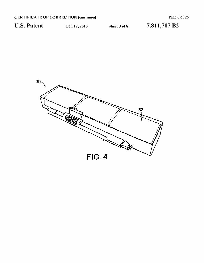
CERTIFICATE OF CORRECTION (continued) Page 6 of 26
U.S. Patent Oct. 12, 2010 Sheet 3 of 8 7,811,707 B2

CERTIFICATE OF CORRECTION (continued) Page 7 of 26
U.S. Patent Oct. 12, 2010 Sheet 4 of 8 7,811,707 B2
H 2r-b 1- 2r-b
Used Cell Space = 7tr + 4r Used CellSpace = 2itr 2 Total Space = cr' + 4r Total Space = tri-- 4r
Utilization - 100.0% %Utilization = (21)/(1 + 4) = 88.096
F.G. 5a FIG. 5b
K- 2r-b
Used Cell Space = Er' + 4r Used Cell Space = r Total Space = 8r Total Space = 8r %Utilization = (at +4)/8 %Utilization = 100.0%
F.G. 5C F.G. 5d.

CERTIFICATE OF CORRECTION (continued) Page 8 of 26
U.S. Patent Oct. 12, 2010 Sheet 5 of 8 7,811,707 B2
Time (Hr.)
F.G. 6
1 O O
9 O
7 O

CERTIFICATE OF CORRECTION (continued) Page 9 of 26
U.S. Patent Oct. 12, 2010 Sheet 6 of 8 7,811,707 B2
O 50 100 150 2OO
Cycle No
FG. 8
100.5%
2 100.0%
L
P 99.5% 2
99.0% Y

CERTIFICATE OF CORRECTION (continued)
Oct. 12, 2010 Sheet 7 of 8 7,811,707 B2 U.S. Patent
g 700 O
500 O 2O 40 60 8O 1OO
% Manganate Spinel
F.G. 10
2O 40 60 8O 100 120
% Manganate Spinel
FIG. 11
O
Page 10 of 26

CERTIFICATE OF CORRECTION (continued) Page 11 of 26
U.S. Patent Oct. 12, 2010 Sheet 8 of 8 7,811,707 B2
%Manganate Spinel
FIG. 12
S. as
2
Y
O 2OO 400 6OO 800 1OOO Cycle No.
FIG. 13

CERTIFICATE OF CORRECTION (continued) Page 12 of 26
US 7,811,707 B2
LITHIUM-ON SECONDARY BATTERY
RELATED APPLICATIONS
This application is a continuation-in-part of U.S. patent 5 application Ser, No. 1474,056, filed on Jun. 23, 2006, now abandoned which is a continuation-in-part of Int'l.App. No. PCT/l JS2005/047383, which designated the U.S. and was fied on Dec. 23, 2005 published in English, which claims the benefit of U.S. Provisional Application No. 60/639,275 filed 10 on Dec. 28, 2004, U.S. Provisional Application No. 60/680, 271 filed on May 12, 2005; and U.S. Provisional Application No. 60699,285 filed on Jul 14, 2005. The entire teachings of the above-mentioned applications are incorporated herein by reference. s
BACKGROUND OF THE INVENTION
Rechargeable batteries, such as lithium-ion rechargeable batteries, are widely used as electrical power for battery- 20 powered portable electronic devices, such as cellular tele phones, portable computers, camcorders, digital cameras, PDAs and the like. A typical lithium-ion batterypack for such portable electronic devices employs multiple cells that are configured in parallel and in series. For example, a lithium- 2's ion battery pack may include several blocks connected in series where each block includes one or more cells connected in paratel. Each block typically has an electronic control that monitors voltage levels of the block. In an ideal configuration, each of the cells included in the battery pack is identical. 30 However, when cells are aged and cycled, cells tend to deviate from the initial ideal conditions, resulting in an unbalanced cell pack tend to deviate from the initial ideal conditions, resulting in an unbalanced cell pack (e.g., unidentical capac ity, impedance, discharge and charge rate). This unbalance 35 among the cells may cause over-charge or over-discharge during normal operation of the rechargeable batteries, and in turn can impose safety concerns, such as explosion (i.e., rapid gas release and possibility for fire).
Traditionally, the conventional lithium-ion rechargeable 40 batteries have employed LiCoO-type materials as the active component of lithium-ion battery cathodes. For such a lithium-ion cell employing LiCoO-type active cathode materials to be fully charged, the charge voltage is usually 4.20W. With lower charging voltage, the capacity is lower, 45 which corresponds to lower utilization of active liCo0. materials. On the other hand, with higher charging voltage, the cell is less safe. In general, it is a challenge for LiCo0 based lithium-ion cells to have a high capacity, for example higher than about 3 Ah due to a high safety concera. In order 50 to minimize the safety concern, lowering the charge voltage is one option. However, this willower the cell capacity, and in turn lower cell energy density, To obtain high capacity, increasing the number of cells in one battery pack may be another option rather than increasing the charge voltage. 55 However, the increase in the number of cells car result in increased probability of unbalance among the cells, which cal cause over-charge or over-discharge during normal operation, as discussed above. The largest Trainstream cell that is typically used in the 60
industry currently is a so-called "8650" cell. This celi has an outer diameter of about 8 mm and a length of 65 mm. Typically, the 3650 cell utilizes LiCoO, and has a capacity between 1800 mAh and 2400 mAh but cells as high as 2600 mAh are currently being used. It is generally believed that it 55 is not safe to use LiCoO, in a larger cell than the l8650 cell becaust of a safety concern associated with LiCoO. Other
2 cells larger than the 18650 cells exist in the art, for example, "26650" cells having an outer diameter of about 26mm and a length of 65 mm. The 26650 cells typically do not contain LiCoO, and have worse performance characteristics interns of Wh/kg and Wh/L than the 18650 cells employing LiCo0
Therefore, there is a need to develop new active cathode materials for lithium-ion batteries that minimize of overcome the above-mentioned problems. In particular, there is a need to develop new active cathode materials that can enable manufacturing large batteries, for example, larger than the conventional LiCoO-based batteries (e.g., 8650 cells) in volume and/or Ah/cell,
SlMMARY OF THE INVENTION
The present invention is generally directed to (l) an active cathode material that includes a mixture of at least one of a lithium cobaltate and a lithium nickelate, and at least one of a manganate spineland an olivine compound, (2) a lithium-ion battery having such an active cathode material, (3) a method of forming such a lithium-ion battery, (4) a battery pack comprising one or more cells, each of the cells including such an active cathode material, and (5) a system that includes such a batterypack or lithium-ion battery and a portableclectronic device,
In one embodiment, the present invention is directed to an active cathode material that includes a mixture of electrode materials. The mixture includes; at least one of a lithiuan cobaltate and a lithium nickelate; and at least one of a man ganate spinel and an olivine compound. The manganate spinel is represented by an empirical for nula of Liu (Mn-A2)-20 where:
x and x2 are each independently equal to or greater than 0.0 and equal to or less than 0.3;
y! and y2 are each independently greater than 0.0 and equal to otless than 0.3;
21 is equal to or greater than 3.9 and equal to or less than 4, 1; and
A" is at least one member of the group consisting of mag nesium, aluminum, cobalt, nickel and chromium. The olivine compound is represented by an empirical for
Inula of Li-A"...MPO, where; x2 is equal to or greater than 0.05 and equal to or less than
0.2, or x2 is equal to or greater than 0.0 and equal to or less than
()., and M is at least one member of the group consisting of iron,
manganese, cobalt and magnesium; and A" is at least one member of the group consisting of
sodium, magnesium, calcium, potassium, nickel and nio bium,
In another embodiment, the present invention is directed to an active cathode material that includes a mixture including: a lithium nickelate selected from the group consisting of LiCoO-coated LiNiCoos Alaos02, and Li(NiaCons Mn)0; and a manganate spinel represented by an empiri cal formula of LMn-O, where x7 and y1 art each independently equats or greater than 0.0 and equato or less than 1.0; and z7 is cqual to or greater than 3.9 and equal to or less than 4.2. The present invention is also directed to a lithium-ion bat
tery having a cathode that includes an active cathode raterial. The active cathode material includes a mixture of electrode materials. The mixture includes: at least one of a lithium cobaltate and a lithium nickelate; and at least one of a man

CERTIFICATE OF CORRECTION (continued) Page 13 of 26
US 7,811,707 B2 3.
ganate spinel and an olivine compound. The Tanganate spine is represented by an empirical formula of Lic (Mn-1A)-O, where:
xl and x2 are each independentiy equal to or greater than 0.0 and equal to or less than 0.3; S
yi and y2 are each independently equal to or greater than 0.0 and equal to or less than 0.3;
Zl is equal to or greater than 3.9 and equal to or less than 4.); and
A' is at least one member of the group consisting of mag- 10 nesium, aluminun, cobait, nickel and chromiurn. The olivine compound is represented by an empirical for
mula of Li-A"MPO. where: x2 is equal to or greater than 0.05 and equal to or less than
0.2, or s x2 is equal to or greater than 0.0 and equal to or less than
(, ; and M is at least one member of the group consisting of iron,
manganese, cobalt and magnesium; and A" is at least one member of the group consisting of 20
Sodiun, magnesium, calcium, potassiurn, nickel and nio biu E.
in one embodiment, the mixture includes: at least one of a lithium cobalitate and a lithium nickelate; and at east one of a manganate spinel and an olivine compound. The manganate 25 spinel and olivine compound are as described above. In another embodiment, the mixture includes: a lithiun nick elate selected from the group consisting of a lithium cobal tate, LiCoO-coated LiNiascootsAlooso, and LiON Cola Mn)0; and a manganate spinel as described above, 30 The battery has a capacity greater than about 3,0Ah/cell.
In yet another embodiment, the present invention is directed to a lithium-ion battery having a cathode that includes an active cathoxie material, the active cathode mate rial comprising a cathode mixture that includes a lithium 35 cobaltate and a manganate spinel represented by an empirical formula of Li (Mini-A)-O, where y land y2 are each independently equal to or greater than 0.0 and equatoor less than 0.3, and the other variables are as described above. The lithium cobaltate and the manganate spinel are in a 40 weight ratio of lithium cobaltate:manganate spine between about 0.95:005 to about 0.55:045.
Also included in the present invention is a battery pack that includes one or more cells, preferably aplurality of cells. The cell(s) of the battery pack are as described above for the 45 lithium-ion batteries of the invention. In one embodiment, the tmixture includes: at least one of a lithium cobaltate and a lithium nickellate; and at least one of a manganate spinel and an olivine compound. The manganate spineland olivine com pound are as described above for the lithium-ion batteries of 50 the invention. In another embodiment, the mixture includes a lithium nickelate selected from the group consisting of a lithium cobaltate, LiCoO-coated LiNiCoosalsO, and Li(NiCoMnO, and a mangamate spinel as described above. Preferably the battery pack includes a plu- SS rality of cells and at least one cell of the cells has a capacity greater than about 3.0Ah/cell. In yet another embodiment, the mixture includes a lithium cobaltate and a manganate spinel represented by an empirical formula of Li(Mn A")-O, wherein the variables are as described above, 60 and the lithium cobaltate and the manganate spinel are in a weight ratio of lithium cobaltate:manganate spinel between about 0.95:0.05 to about 0.55:0.45. A method of forming a lithium-ion battery having a cath
ode that includes an active cathode material as described 65 above is also included in the present invention. The method includes forning an active cathode material as described
4 above. The method further includes the steps of forming a cathode electrode with the active cathode material; and form ing an anode electrode in electrical contact with the Cathode electrode via an electrolyte, thereby forming a lithium-ion battery A system that includes a portable electronic device and a
batterypack as described above is also included in the present invertion. The lithium-ion batteries of the invention, which employ a
novel blend of two or more different types of active cathode materials in the positive electrode, have safer chemistry char acteristics than conventional lithium-ion batteries that solely employ LiCoC, as the active material of the lithium-ion bat tery cathodes. In particular, an active cathode material of the invention enables manufacturing of large batterics, e.g., larger than the 18650 cells, for use in these mobile devices partly due to its safety and high capacity in terms of energy density and power density. The present invention also allows for economical manufacturing of larger cells compared to what is common in today's industry (e.g., the 18650 cells), in part due to lower cathode costs and in part due to lower electronics costs. These higher capacity type cells allow lower cost without sacrificing overall safety. These higher capacity type cells can in turn minimize the number of elec tronic components needed for charge control, which allows lowering of electronic component costs overall for a battery pack utilizing multiple cells connected in series or parallel. The present invention can be used in mobile electronic
devices such as portable computers, cellphones and portable power tools. The present invention can also be used in batter ies for hybrid electric vehicles.
BRIEF DESCRIPTION OF THE DRAWINGS
FIG. is a sectional view of a cylindrical-shaped lithium ion battery typical of that used commercially today and spe cifically representative of an 18650 type lithium-ion battery.
FIG. 2 is a schematic representation of an example of an oblong-shaped can for a lithium-ion battery of the invention.
FIG. 3 is a schematic circuity showing how cells in the invention are preferably connected when arranged together in a battery pack.
FIG. 4 is a photographic top, see-through view of a battery pack of the invention.
FIGS. 5(a)-5(d) are schematic drawings comparing differ ent spatial utilizations of different battery form factors includ ing the battery of this invention (FIG. 5(a)) and comparison examples typical of commercial batteries used today includ ing two 18650 cells in parallel (FIG. 5(b)), a prismatic cell containing a woundjelly roll electrode structure (FIG. 5(c)) and a prismatic cell containing a stacked electrode structure (FIG, 5(d)).
FIG. 6 is a graph showing typical charge curves of a battcry of the invention and a control battery at room temperature.
FIG. 7 is a graph showing relative capacity retention during charge-discharge cycling at room temperature of a battery of the invention and two control batteries: cycling conditions: constant charge constant voltage (CCCV) charging using 0.7 C constant charge followed by constant voltage charge at 4.2 v and then C discharge to 2.75 W.
F.G. 8 is a graph showing Telative capacity retention during charge-discharge cycling at 60° C. of a battery of the inven tion and a control battery under the conditions described in FG. T. FIG.9 is a graph showing the rate capability for an average
and standard deviation of eight batteries of the invention and two control commercial 8650 batteries where the batteries

CERTIFICATE OF CORRECTION (continued) Page 14 of 26
US 7,811,707 B2 5
are charged under the charge conditions described in FIG. 7 and discharged to 2.75 W at the rates indicated in the figure.
FIG. 10 is a graph showing the total heat of reaction of cathode mixtures of the invention, which includes a lithium Cobaltate and a manganate spinel, and of the lithium cobal tatt- and the manganate spinel, in DSC tests.
Flg. 11 is a graph showing the maximum heat flow during reaction of cathode mixtures of the invention, which includes a lithium cobaltate and a manganate spine, in DSC tests.
FIG, 12 is a graph showing time spent by a lithium-ion battery of the invention, which includes a cathode mixture that includes a lithium cobaltate and a manganate spinel, prior to rapid cell reaction (e.g., fire or explosion) during abuse testing.
FIG. 13 is a graph showing cyclability of a lithium-ion battery of the invention, which includes 70 wt % of LiCoO, and 36 wa of Li MnO, as an active cathode material, and showing cyclability of two commercially available 18650 batteries with 100 wt % of LiCoO, as an active cathode material.
DETAILED DESCRIPTION OF THE INVENTON
The foregoing and other objects, features and advantages of the invention will be apparent from the following more particular description of preferred embodiments of the inven tion, as illustrated in the accompanying drawings in which like reference characters refer to the same parts throughout the different views. The drawings are not necessarily to scale, emphasis instead being placed upon illustrating the principles of the irivetition.
In one embodiment, the present invention relates to an active cathode material mixture that can be employed in an clectrode of a lithium-ion battery that allows lithium to be reversibly intercalated and extracted. The active cathode material comprises a mixture that includes: at least one of a lithium cobaltate and a lithium nickelate; and at least one of a manganate spinel and an olivine compound, A lithium nickelate that can be used in the invention
includes at least one modifier of either the Liatom or Niatom, or both. As used herein, a "modifier" means a substituent atom that occupies a site of the Liatom or Niatom, or both, in a crystal structure of LiNiC. In one embodiment, the lithium nickelate includes only a modifier of Liatom ("Limodifier'). In another embodiment, the lithiurn nickelate includes only a modifier of Niatom (Nimodifier'). In yet another embodi ment, the tithiun nickelate includes both of the Li and Ni modifiers. Examples of the Li modifier include barium (Ba), magnesium (Mg), calcium (Ca)and strontium (Sr). Examples of the Ni modifier include those modifics for Li and in addition aluminum (Al), manganese (Mn) and boron (B). Other examples of the Nimodifier include cobalt (Co) and titanium (Ti). Preferably, the lithium nickelate is coated with LiCoO). The coating can be a gradient coating or a spot-wise coating. One particular type of a lithium nickelate that can be used
in the invention is represented by an empirical formula of LiNi-M'O where 0.053x3<1.2 and 0<z3<0.5, and M' is one or Enore elements selected from a group consisting of Co, Mn, A, B, Ti, Mg, Ca and Sr, Preferably, M' is one or more elements selected from a group consisting of Mn, A, B, Ti, Mg, Ca. and Sr.
Another particular type of a lithium nickelate that can be used in the invention is represented by an empirical formula of li. As Ni-CoQO, where x4 is equal to or greater than about 0.1 and equal to or less than about .3; x5 is equal to or greater than 0-0 and equal to or less than about
O
s
20
25
3.
35
SO
s
s
6 0.2; y4 is equal to or greater than 0.0 and equal to or less than about 0.2; 24 is equato orgreater than 0.0 and equal to or less than about 0.2; a is greater than about 1.5 andless than about 2.; A is at least one member of the group consisting of barium (Bay, magnesium (Mg) and calcium (Ca); and Q is at least one member of the group consisting of aluminum (Al), manganese(Mn) and boron (B). Preferably, y4 is greater than zero. In one preferred embodiment, X5 is equal to zero, and 24 is greater than 0.0 and equai to or less than about 0.2. In another embodiment, 24 is equal to zero, and x5 is greater than 0.0 and equal to or less than about 0.2. In yet another embodiment, x5 and 24 are each independently greater than 0.0 and equal to or less than about 0.2. In yet another embodi ment, x5,y4 and z4 are each independently greater than 0.0 and equal to or less than about 0.2. Warious examples of lithium nickelates where x5, y4 and 24 are each indepen dently greater than 0.0 and equal to or less than about 0.2 can be found in U.S. Pat. Nos. 6,855,461 and 6,921,609 (the entire teachings of which are incorporated herein by reference), A specific example of the lithium nicketate is
LiNiCoosalooso. A preferred specific example is LiCoO-coated LiNiCoos Aloo,0,. The spot-wise coated cathode has LiCoO not fully coated on top of a nickelate core particle, so that the higher reactivity nickelate is deactivated and hence safer. The composition of LiNiCo. Alps coated with LiCoO can naturally deviate slightly in compo sition from the 0.8:0.15:005 weight ratio between Ni:Co:Al. Deviation may be approximately 10-15% for the Ni, 5-10% for Co and 2.4% for A.
Another specific example of the lithiu), nickelate is LiMgolo NiCo. O. A preferred specific example is LiCoO-coated Lio,Mgolo Nio Coo. O. The spot-wist coated cathode has LiCoO, not fully coated on top of a nick elate core particle, so that the higher reactivity nickelate is deactivated and hence safer. The composition of Loo,MgooNiCo, O, coated with LiCoO, can naturally deviate slightly in composition from the 0.03:09:0.1 weight ratio between Mg:Ni:Co. Deviation may bc approximately 2-4% for Mg, 10-15% for Niand 5-10% for Co.
Another preferred nickelate that can be used in the present invention is Li(Ni,Co.Mn)0, which is also called "333-type nickelate.” This 333-type nickelate can be option ally coated with LiCoO, as described above.
Suitable examples of lithium cobaltates that can be used in the invention include LiCo0 that is modified by at least one of modifiers of Li and Coatoms. Examples of the Limodifiers are as described above for Li for LiNiO. Examples of the Co modifiers include the modifiers for Li and aluminum (Al), manganese (Mn) and boron (B). Other examples include nickel (Ni) and titanium (Ti). Particularly, lithium cobaltates represented by an empirical formula of Lism-scot-s) M"O, where x6 is greater than 0.05 and less than .2; yé is equal to or greater than 0 and less than 0.126 is equal to ot greater than 0 and less than 0.5; M' is at least one member of magnesium (Mg) and sodium (Na) and M" is at least one member of the group consisting of manganese (Mn), alumi rum (Al), boron (B), titanium(Ti), Inagnesium (Mg), calcium (Ca) and strontium (Sr), can be used in the invention.
Another example of lithium cobaltates that can be used in the invention includes LiCo0.
It is particularly preferred that the compounds have a spherical-like morphology as this improves packing and pro duction characteristics.
Preferably, a crystal structure of each of the lithium cobal tate and lithium nickelate is independently a R-3m type space group (rhombohedral, including distorted rhombohedral). Alternatively, a crystal structure of the lithium nickelate can
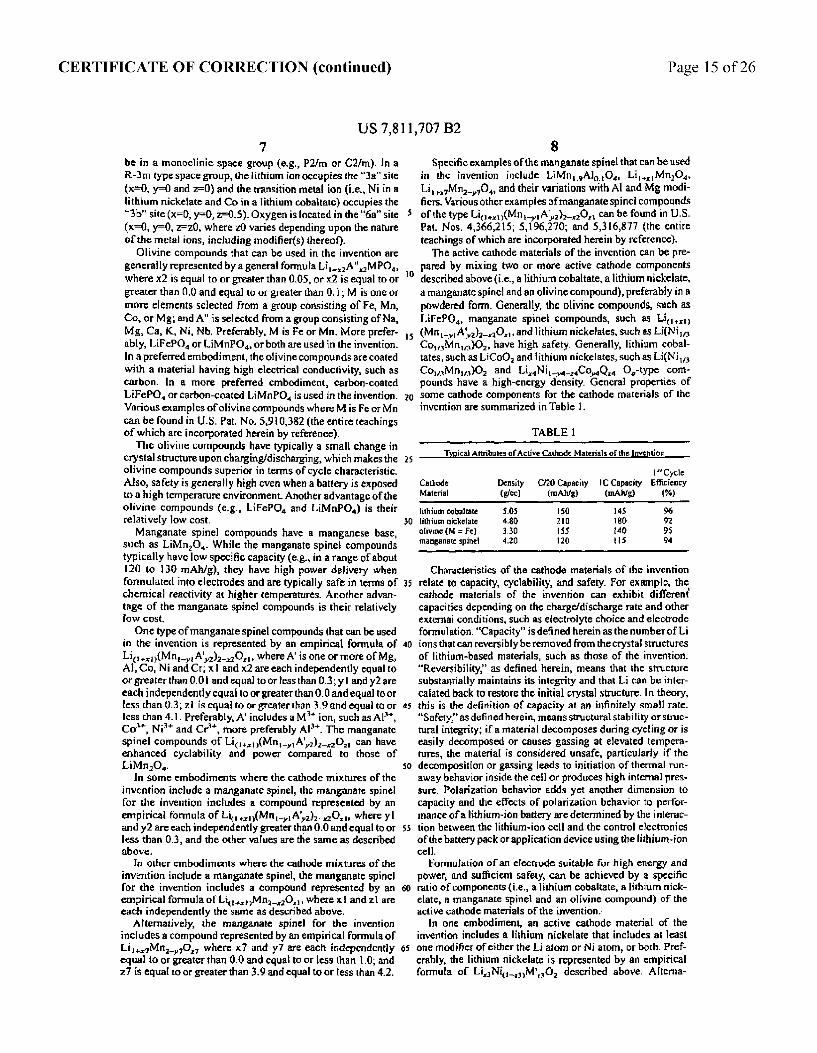
CERTIFICATE OF CORRECTION (continued) Page 15 of 26
US 7,811,707 B2 7
be in a monoclinic space group (e.g., P2fm or C2/m). In a R-3T type space group, the lithium ion occupies the "3a' site (xe-0, y=0 and z=0) and the transition metal ion (i.e., Ni in a lithium nickelate and Co in a lithium cobalitate) occupies the "3b' site (x-0, y0, z=0.5). Oxygen is located in the "6a" site (x=0, y0, z=z0, where z0 varies depending upon the nature of the metal tons, including modifier(s) thereof).
Olivine compounds that can be used in the invention are generally represented by a general formula Li-A"MPO, where x2 is equal to or greater than 0.05, or x2 is equal to or greater than 0.0 and equal to or greater than 0, i, M is one or more elements selected from a group consisting of Fe, Mn, Co, or Mg; and A" is selected from a group consisting of Na, Mg, Ca, K, Ni, Nb. Preferably, M is Fe or Mn. More prefer ably, LiFePO oriMnPO or both are used in the invention. In a preferTed embodiment, the olivine compounds are coated with a material having high electrical conductivity, such as carbon. In a more preferTed embodiment, carbon-coated LifePO or carbon-coated LiMnPO is used in the invention. Warious examples of olivine compounds where M is Fe or Mn can be found in J.S. Pat, No. 5,910,382 (the entire teachings of which are incorporated herein by reference). The olivine compounds have typically a small change in
crystal structure upon charging/discharging, which makes the olivine compounds superior in terms of cycle characteristic. Also, safety is generally high even when a battery is exposed to a high temperature environment. Another advantage of the olivine compounds (e.g., LiFePO and LiMnPO) is their relatively low cost. Manganate spinel compounds have a manganese base,
such as LiMnO. While the manganate spinel compounds typically have low specific capacity (e.g., in a range of about 120 to 130 mAh/g), they have high power delivery when formulated into electrodes and are typically safe in terms of chemical reactivity at higher temperatures. Another advan tage of the manganate spinel compounds is their relatively low cost, One type of manganate spinel compounds that can be used
in the invention is represented by an empirical formula of Lic (Mn-A2)-O, where A' is one or more of Mg, Al, Co, Ni and Cr;xl and x2 are each independently equal to or greater than 0.01 and equal to or less than 0.3;yl and y2 are each independently equato or greater than 0.0 and equal to or less than 0.3; Z is equal to or greater than 3.9 and equal to or less than 4.1. Preferably, A' includes a M ion, such as Al', Co, Ni and Cr', more preferably Al'. The manganate spinel compounds of Li (Mini-A)-O. can have enhanced cyclability and power compared to those of LiMnO.
In some embodiments where the cathode mixtures of the invention include a manganate spinel, the manganate spinel for the invention includes a compound represented by an empirical formula of li(Mn-A2)-O, where y andy2 are each independently greater than 0.0 and equal to or less than 0.3, and the other values are the same as described above.
In other embodiments where the cathode mixtures of the invention include a manganate spinet, the manganate spinel for the invention includes a compound represented by an empirical formula of Li-MnO, where x and zl are each independently the same as described above.
Alternatively, the nanganate spine for the invention includes a compound represented by an empirical formula of LiMnO, where x7 and y7 are each independently equal to or greater than 0.0 and equal to or less than l.0; and z7 is equal to or greater than 3.9 and equal to or tess than 4.2.
O
s
RS
30
35
4.
as
SO
SS
6
5
8 Specific examples of the manganate spinel that can be used
in the invention include LiMn. AlO, Li Mn2O4. LiMnO, and their variations with Al and Mg modi fiers. Warious other examples of manganate spinel compounds of the type Li(Mn-1A).-O. can be found in U.S. Pat. Nos. 4,366,25; 5,196,270; and 5,316,877 (the entire teachings of which are incorporated herein by reference). The active cathode materials of the invention can be pre
pared by mixing two or more active cathode components described above (i.e., a lithium cobaltate, a lithium nickelate, a manganate spineland an olivine compound), preferably in a powdered form. Generally, the olivine compounds, such as LiFe?pO, manganate spinel compounds, such as Lili (MEA)-O, and lithium nickelates, such as Ei(Nila CoMn)0, have high safety. Generally, lithium cobal tates, such as LiCoO, and lithium nickelates, such as Li(Nila CoMn)O and LiNi--CoQ O-type comi pounds have a high-energy density, General properties of some cathode components for the cathode materials of the invention are summarized in Table 1.
TABLE
Typical Attributes of Active Cathode Materials of the Invention I'Cycle
Cathode Density C20 Capacity C Capacity Efficiency Matetia (gic) Ahlg) (IAg) (%)
lithium cobacate SS 4S 9. lithiurn ticktilate 4.80 BO 92 olivine (M = Fe) 30 s 4. 95 Targanate spire 4.20 120 s
Characteristics of the cathode materials of the invention relate to capacity, cyclability, and safety. For example, the cathode materials of the invention can exhibit different capacities depending on the chargeldischarge rate and other external conditions, such as electrolyte choice and electrode formulation. "Capacity" is defined herein as the number of Li ions that can reversibly be removed from the crystal structures of lithium-based materials, such as those of the invention. "Reversibility as defined herein, means that the structure substantially maintains its integrity and that i can be int caiated back to restore the initial cystal structure. In theory, this is the definition of capacity at an infinitely small Tafe. "Safety" as defined herein, means structural stability or struc tural integrity, if a material decomposes during cycling or is easily decomposed or causes gassing at elevated tempera tures, the material is considered unsafe, particularly if the decomposition orgassing leads to initiation of thernal Tun away behavior inside the ceil or produces high internal pres sure. Polarization behavior adds yet another dimension to capacity and the effects of polarization behavior to perfor mance of a lithium-ion battery are determined by the interac tion between the lithium-ion cell and the control electronics of the battery pack or application device using the lithium-ion cell,
Formulation of an electode suitable for high energy and power, and sufficient safety, can be achieved by a specific ratio of components (i.e., a lithium cobaltate, a lithiurn nick elate, a mangariate spinel and an olivine compound) of the active cathode materials of the invention.
ln one embodiment, an active cathode naterial of the invention includes a lithium nickelate that includes at least one modifier of either the Liatom or Natom, or both. Pref erably, the lithium nickelate is represented by an empirical formula of LiNi-MO, described above. Alterna

CERTIFICATE OF CORRECTION (continued) Page 16 of 26
US 7,811,707 B2
tively, the lithium nickelate is represented by an empirical formula of LiA"Ni--CoOO, described above. In a specific example, the lithium nickelate is represented by an empirical formula of LiA"Ni-CoQ.O. where x5, y4 and 24 are each independently greater than 0.0 and equal to or less than about 0.2. Specific examples of the lithium nickclate are as described above.
in a second embodiment, an active cathode material of the invention includes a lithium cobaltate represented by an empirical formula of LiCo-M"O. described above. Specific examples of the lithium cobaltate are as described above,
In a third embodiment, an active cathode material of the invention includes an olivine compound represented by an empirical formuia of Li-A"MPO described above. Specific examples of the olivine compound are as described above. ln apreferredcmbodiment, Misiron or magnesium, in a Prefer Ted embodiment, the olivine compound is coated with carbon.
lin a fourth embodiment, an active cathode material of the invention includes a lithium cobaltate, such as LiCoO, and a manganate spinel. The lithium cobaltate and manganate spinel, including specific examples thereof, are as described
s
above. Preferably, the lithium cobaltate, and manganate spine are in a weight ratio of lithium cobaltate:manganate spine? between about 0.8:02 to about 0.4:0.6. In one example of the fourth embodiment, the manganate spinel is repre sented by Li (Mini-A)-O, in another example of the fourth embodiment, the Tanganate spinel is represented by Li-Min-O, preferably Li,MnO, (e.g., Li MO). In yet another example of the fourth embodiment, the manganate spinel is represented by Li MnO, in a fifth embodiment, an active cathode material of the invention includes a lithium nicketate and a manganate spinel repre Sented by Li(Mn-A2)-O, described above. The lithium nickelate and manganate spinel, including specific exampics thereof, are as described above. Preferably, the lithium nickelate and manganate spinel are in a weight ratio of lithium nickelate:manganate spinel between about 0.9.0.4 to about 0.3.0,7. In one example of the fifth embodiment, the lithiu nickellate is LiNts Cola Mn).O., LiNio gCooosAloos02 or Lio,Mgoloniosco. O. Prefer ably, the lithium nickelate is LiCoO-coated, LiNios Coolis Alaogo, or Liog,MgosNio Coooo... When LiCoO-coated, LiNio Cools.Alooso, o Lics, Mg,NigCo.O. is used, the lithium nickelate and Tanganate spinel are preferably in a weight ratio of lithiun nickelate-to-manganate spinel between about 0.9:0.1 to about 0.3:0.7. When LiNiCoMn)O, is used, the lithium nickellatt and manganate spinel are preferably in a weight ratio of lithium nickelate:manganate spinel between about O. :03 to about 0.3:O..
In a sixth embodiment, an active cathode material of the invention includes at least one lithium (nickelate selected from the group consisting of Li(NiCoMn)O and LiCoO Coated LiNioscools Aloso; and a manganate spinel repre sented by Li. Mn-O, preferably Li MnO, such as LiMnO, Preferably, the lithium nickelate and manganate spinel are in a weight ratio of lithium nickelate:Inanganate spine between about 0.9:0. to about 0.3:0.7. When Li(Ni CoMn)O is used, the lithium nickelate and manganate spinei are in a weight ratio of lithium nickelate:manganate spine between about 0.9:0. to about 0.5:0.5.
In a Seventher bodiment, the active cathode material of the invention includes a lithium cobaltate, such as LiCo0, a manganate spinel and a lithium nickelate. The lithium cobal tate, manganate spinel and lithium nickelate, including spe
s
30
35
45
5
SS
5
10 cific examples thereof, areas described above. Preferably, the lithium cobaltate, manganate spinel and lithium nickelate are in a weight ratio of lithium cobaltate:manganate spinel: lithium nickelate between about 0.05 and about 0.8; between about 0.05 and about 0.7 (e.g., between about 0.05 and about 0.3, or between about 0.3 and about 0.7): between about 0.05 and about 0.9 (e.g., between about 0.4 and about 0.9, or between about 0.05 and about 0.8). In one example, the lithiurn nickeiate is represented by Lia A's Nic CoQo in a second example, the lithium nickelate is represented by lini-M.O. Llore preferably LiNiCo. Alo,0, that is gradient- or spot-wise coated with LiCoO. In a third example, the lithium nickelate is Li(NiCoMn).O. En a fourth example, the lithium nickelate includes at least one modifier of both the Li and Ni atoms, such as Li, A's.Ni-CoQ.O. where x.5, y4 and z4 are each independently greater than 0.0 and equal to or less than about 0.2, and the manganate spinel is Tepresented by Li (Mini-A):-O, Preferably, when Lia.A. Ni--4CoQ.40 and Li-Min-yi Ay2)-2 O are used, the tithium cobaltate, manganate spinel and lithium nickeiate are in a weight ratio of lithium cobaltate: manganate spinel: lithiun nickelate between about 0.05 and about 0.30; between about 0.05 and about 0.30; between about 0.4 and about 0.9. In a fifth example, the lithium nick elate is Li(NiCo,Mn)0, or optionally LiCoO-coated LiNiCo. Also, and the Tanganate spinel is repre sented by Li(Mn-A2).-O. In this fifth example, when LiNiCoaMnO, is used, LiNiCoaMn) O, Li(Mn-A):-O and lithium coballate are in a weight ratio of Li(NiCo,Mri)O, Li(Mn A)-O, lithium cobaltate between about 0.05 and about---08 between about 0.3 and about-0.7: between about 0.05 and-about 0.8.
In an eighth embodiment, an active cathode material of the invention includes two or more lithiui in nickellates and a man ganate spinel. The lithium nickelates and manganate spinel, including specific examples thereof, are as described above. Preferably, lithium nickelates and manganate spiriel are in a weight ratio of lithium nickelates:manganate spinel between about 0.05 and about 0.8: between about 0.05 and about 0.9. Preferably, the manganate spinel is represented by Li (Mn-A).-O. In one example, the lithium nickelates include a lithium nickelate represented by LiA's Ni-CoQ10 in another example, the lithium nick elates includes a lithium nickelate represented by LiNi M.O. Alternatively, the lithium nickelates includes a lithium nickelate including at least one modifier of both the Li and Niatoms, such as Eli A. Ni--CoQO where x5, y4 and 24 are each independently greater than 0.0 and equal to or less than about 0.2. En a specific example, the lithium nickelates include Li(NiCoME}O and a lithium nickelate represented by LiA's Ni-- CoQ.O. in another specific example, the tithium nick elates include Li(NiCo, Mn.)0, and a lithium nickelate that includes at least one modifier of both the Liand Niatoms, such as LiANi - CoQ10 where x5, y4 and 24 are each independently greater than 0.0 and equal to or less than about 0.2. In yet another specific example, the lithium nickelates include LiNiCoMn)0 and a lithium nick elate represented by LiA", Ni-CoQ.C., and the manganate spinel is represented by Li-Mn-1A)-2 O. In this specific example, the lithium nickelates and man ganate spinel are in a weight ratio of Li(NiCoMn)O: LiA"Nii-CoQ.O.Li (Mini-y:A-2)-2O. betweeabloidao 08 elabof 665 and about 0.7: between about 0.05 and about 0.9.

CERTIFICATE OF CORRECTION (continued) Page 17 of 26
US 7,311,707 B2
In a ninth embodiment, an active cathode material of the invention includes a lithium cobaltate, such as LCo0, and an olivine compound represented by Li-A"...MPO. described above, preferably coated with carbon. The lithium cobaitate and olivine compound, including specific examples thereof, areas described above. Preferably, the lithium cobal tate and olivine compound are in a weight ratio of lithium cobaltate:olivine compound between about 0.9.0.1 to about 0.3:0.7. In one example, the olivinc cornpound is represented by Li-A"...MPO where M is iron or manganese, such as LifePO, and LiMnPO in this example, preferably, the lithium cobaltate and olivine compound are in a weight ratio of lithium cobaltate:olivine compound between about 0.8:0.2 to about 0.4:06,
In a tenth embodiment, an active cathode material of the invention includes a lithiun nickeiate, and an olivine comr pound represented by Li-A"MPO described above, preferably coated with carbon. The lithium nickelate and olivine compound, including specific examples thereof, areas described above. Preferably, the lithium nickellate and olivine compound are in a weight ratio of lithium nickelate:olivine compound between about 0.9.0. to about 0.3:0.7. In one example, the olivine compound is represented by Li A"...MPO where M is iron or Inanganese, such as LiFePO and LiMnPO. In a second example, the lithium nickelates include a lithium nickelate represented by LiA", Ni--CoOO. In a third example, the lithium nick clates includes a lithium nickelate represented by LN MO. Alteratively, the lithium nickelates includes a lithium nickelate including at teast one modifier of both the Li and Niatons, such as L.A's Ni-CoQO, where x5, y4 and 24 are each independlygat: than .O and equal to or less than about 0.2. In a specific example, the lithium nicketate is Li(NiCoMn)O, and the olivine compound is represented by Li-A"MPO, where M is iron or manganese. Preferably, in the second example, the lithium nickelate and olivine compound are in a weight ratio of lithium nickelate:olivine compound between about 0.9:0. to about 0.5:0.5. In a second specific example, the lithium nickelate is represented by LiA"Ni--CoQ.O. Preferably LiA's Ni-CoQC, where x5, y4 and 24 are each independently greater than 0.0 and equal to or less than about 0.2, and the olivine compound is represented by LiA"MPO, where M is iron or manganese. In a third specific example, the lithium nickelate is LiNiosCools Aloioso, preferably LiCoO-coated LiNiosCoo. Alois0, and the olivine compound is repre sented by Li-A"...MPO where M is iron or manganese. Preferably, in the third specific example, the lithium nickelate and olivine compound are in a weight ratio of lithium nick elate:olivine compound between about 0.9:0.) to about 0.3: 0.7.
In an eleventh embodiment, an active cathode material of the invention includes two or more lithium nickelates, and an olivine compound, preferably an olivine compound repre sented by Li-A"MPO, where M is iron or manganese. The lithiur nickeiates and olivine compound, including spe cific examples thereof, areas described above. Preferably, the olivine compound is coated with carbon. In this embodiment, the lithium nickelates and olivine compound are in a weight ratio of lithium nickelates:olivine compound between about 0.05 and about 0.9; between about 0.05 and 0.9. In one example, the lithium nickelates include a lithium nickelate represented by Li. AsNi-CoQO. In another example, the tithium nickellates includes a lithium nickelate represented by Li, Ni-MO. Alternatively, the lithium nickelates includes a lithium nickelate including at least one
s
s
35
s
SS
SS
12 modifier of both the Li and Ni atoms, such as Li. As Ni-CoQ0, where x5,y4 and 24 are each indepen dently greater than 0.0 and equal to or less than about 0.2. In a specific example, the lithium nickelate is represented by an empirical formula of li.A.Ni----Co, QC where x5, y4 and 24 are each independently greater than 0.0 and equal to or less than about 0.2. In one specific example, the olivine compound is represented by Li-2A"MPO where M is iron or manganese, such as lifeb. and LiMnPO, and the lithium nickeiates include Li(NiCoMnO and a lithium nickelate including at leastone modifier of both the Li and Niatoms, such as LiA's Ni-CoOO, where x5, y4 and 24 are each independently greater than 0.0 and equal to or less than about 0.2. In this example, the lithium nickelates and olivine compound are preferably in a weight ratio of Li(NiCo,Mn)0: lithium nickelate: olivine compound between about 0.05 and about 0.8: between about 0.05 and about 0.7: between about 0.05 and about 0.9.
In a twelfth embodiment, an active cathode material of the invention includes a lithium nickelate, a lithium cobaltate, such as LiCoO, and an olivine compound represented by Li-A"...MPO described above. The lithium nickelate, lithium cobaltate and olivine compound, including specific examples thereof, are as described above. In this embodi ment, the lithium nickelate, lithium cobaltate and olivine compound are preferably in a weight ratio of lithium cobal tate:olivine compound:lithium nickelate between about 0.05 and about 0.8; betweers about 0.05 and about 0.7: between about 0.05 and about 0.9. in one exampfe, the lithium nick elates include a lithium nickelate represented by LiA's Nia--C-Q-9. in another example, the lithium nick elates includes a lithium nickelate represented by Li, Ni MO, Aternatively, the lithium nickelates includes a lithium nickelate including at leastone modifier of both the Li and Ni atoms, such as LiA's Ni----CoOO, where x5, y4 and 24 are each independently greater than 0.0 and equal to or less than about 0.2. In one specific example, the lithium nickelate is represented by LiA's Ni-- CoQ.O. preferably Lisa's Ni--CoQ.O. where x5, y4 and 24 are each independently greater than 0.0 and equal to or tess than about 0.2, and the olivine compound is represented by Li-A"MPO, where M is iron or manga nese in this specific example, the lithium nickelate, lithium cobaitate and olivine compound are preferably in a weight ratio of lithium cobaltate:olivine compound: lithium nick elate between about 0.05 and about 0.30: between about 0.05 and about 0.30; between about 0.4 and about 0.9. In a second specific example, the lithium nickelate is Li(NiCo Mn)0, and the olivine compound is represented by LiA"MPO, where M is iron or manganese. In the second specific example, preferably the lithium nickelate, lithium cobaltate and olivine compound are in a weight ratio of lithium nickelate:olivine; lithium cobaltate between about 0.05-08: about 0.3-0.7: about 0.05-08. In a third specific example, the lithium nickelate is LiNiascoots Alooso, pref erably LiCoO-coated LiNioacoots Alood, and the olivine compound is represented by Li-A"MPO, where M is iron or Tanganese.
in a thirteenth embodiment, an active cathode material of the invention includes a manganate spinel, an olivine com pound, preferably an olivine compound represented by LA"MPO, where M is iron or manganese, and a lithium nickelate. The manganate spinel, olivine compould and lithium nickelate, including specific examples thereof, are as described above. In this ebodiment, Finanganate spine), olivine compound and lithium nickelate are preferably in a weight ratio of manganate spinel:olivine; lithium nick elate
CERTIFICATE OF CORRECTION (continued) Page 18 of 26
US 7,811,707 B2 13
between about 0.05-09: about 0.05-09: about 0.05-09. In one example, the manganate spinel is represented by Li (Mn-A), O.. In another example, the manganate spinel is represented by Li,Mn2O. In yet another example, the manganate spinel is represented by Li is MnO, such as LiMnO. In one specific example, the man ganate spinel is represented by Liu (Mini-A)-O. and the lithium nickeiate includes at leastone modifier of both the Li and Ni atoms, such as a lithium nicketate represented by Li. As Ni--CoQ.O. where x5, y4 and z4 are each independently greater than 0.0 and equal to or less than about 0.2. In a second specific example, the manganate spinel is represented by Li-i(Mn-A2)-O, and the lithium nickelate is represented by Li. Ni-M'0, preferably s iNioacools AloosQ, more preferably LiCoO-coated
liNio Coos Aloos0. In a third specific example, the man ganate spinel is represented by Liu (Mini-A)-O. and the lithium nickelate is Li(NiCoMnO, In a fourth specific example, the manganate is represented by 20 iMn-70 or Li MnO, or is a variation thereof
modified with A and Mg, and the lithium nickelatcissclected from the group consisting of Li(NiCoMn)O, and LiCoO2-coated LiNioscoots Alois0.
En a fourteenth embodiment, an active cathode material of 25 the invention includes two or more lithium nickelates as described above. In one example, the active cathode material includes Li(NiCo,Mn)O. In a specific example, the active cathode material includes Li(NiCoMnO, and a lithium nickelate including at least one modifier of both the 30 Li and Ni atoms, such as a lithium nickelate represented by i.A.Ni-CoQO, where x5, y4 and 24 are each
independently greater than 0.0 and equal to or less than about 0.2. Preferably, in this example, the lithium nickelates are in a weight ratio of Li(NiCoMnia)0,:LiA"Ni-- 35 CoQ.O. between about 0.7:0.3 to about 0.3:0.7. Enanother specific example, the active cathode material includes Li(Nirs Colis Mn)2, and iNiocoon. Aloioso, more preferably iCoO-coated LiNiCoAO. Prefer ably, in this example, the lithium nickelates are in a weight 40 ratio of Li(NitraCoaMn)0:LiNiosCools.Aloso, between about 0.8:0.2 to about 0.2:0.8.
In a fifteenth embodiment, an active cathode material ofthe invention includes a lithium cobaltate and a manganate spinel, as described above. In a preferred embodiment, the 45 manganate spiel is represented by an empirical formula of li(Mn-1A)-O, wherein the variables are as described above, Examples of the lithium cobaltate, includ ing preferred values, are as described above. In this embodi ment, the lithium cobaltate and the manganate spinel are in a 50 weight ratio of lithium cobaltate:manganate spinel between about 0.95:0.05 to about 0.55:0.45, preferably between about 09:0. to about 0.6:0.4, more preferably between about 0.8: 0.2 to about 0.6:04, even more preferably between about 0.75:0.25 to about 0.65:0.45, such as about 0.7:0.3. 55
In the fifteenth embodiment, preferably, the lithium cobal tate is represented by an empirical formula of LiM's Co-M"O where x6 is greater than 0.05 and less than .2; ye is greater than or equal to 0 and less than 0.1; Z6 is
equal to or greater than 0 and less than 0.5; M' is at least one 60 of magnesium (Mg) and sodium (Na) and M" is at least one member of the group consisting of manganese, aluminum, boron, titanium, magnesiurn, calciurn and strontium. In one specific Inbodiment, the lithium cobaltate is LiCoO doped with Mg, and/or coated with a refractive oxide or phosphate, 65 such as ZrO, or Al(PO) in another specific embodiment, the lithium cobaltate is LiCoO, with no modifiers.
4 In the fifteenth embodiment, preferably, the manganate
spinel does not have the A' modifier, i.e., y2 is equal to zero in the formula of Li (Mn-1A)-01. In a specific embodiment, the manganate spinel includes a compound rep resented by an empirical formula of Li-MnO, where the variables are as described above. In another specific embodiment, the manganate spinel includes a compound rep resented by an empirical formula of iMn-O, where the variables are as described above, preferably Li, Mn.-O. Alternatively, the manganate spinel includes a compound represented by an empirical formula of Li (Mn-A), O... where y and y2 are each indepen dently greater than 0.0 and equal to or less than 0.3, and other values are the same as described above.
In a even more preferred embodiment where the active cathode material includes a lithiun cobaltate and a mangan ate spinel, the lithium cobaltate is LiCoO, with no modifiers and the manganate spinel does not have the A' modifier.
Another aspect of the present invention is directed to a lithium-ion battery that employs the active cathode materials of the invention described above, Preferably, the battery has a greater than about 2.2 Ahcell capacity, More preferably, the battery has a greater than about 3.0 Ah/cell capacity, such as equal to or greater than about 3.3Ah/cell; equal to or greater than about 3.5 Ah cell; equal to or greater than about 3.8 Ahlcell; equal to or greater than about 4.0 Ahcell; equal to or greater than about 4.2Ah/cell; between about 3.0Ah/cell and about 6 Ahcell; between about 3.3 Ah/cell and about 6 Ahlcell; between about 3.3 Ah/cell arid about 5 Ah/cell, between about 3.5Ahcell and about 5Ahcell between about 3.8 Ahcet and about 5 Ah cell, and between about 4.0 A?cell and about 5 Ah cell.
En one embodiment, the batteries of the invention include an active Cathode material including a mixture that includes: at leastone of a lithium cobaitate and a lithium nickelate; and at least one of a manganate spinel represented by an empirical formula of Li(Mn-A2).O. described above and an olivine compound represented by an empirical formula of Li-A"MPO described above. In another embodiment, the batteries of the invention include an active cathode Inate rial including a mixture that includes: at least one of a lithium cobaltate and a lithium nickelate selected from the group consisting of LiCoO-coated LiNioscos Alooso, and LicNiCoMn)O; and a manganate spinel having an empirical formula of Liu Min-Odescribed above. In yet another embodiment, the batteries of the invention include an active cathode materiai including a mixture that includes: a lithium nickelate selected from the group consisting of LiCoO-coated LiNioscos Alaos), and Li(NiCo Mn)O, and a manganate spinel having an empirical for mula of LiMnO, described above. The batteries each independently have a capacity as described above, pref erably greater than about 3.0 Ahlceil.
In a prefered embodiment, cell building for the batteries of the invention utilize a larger format interns of Ahfcell than is currently used in the industry such as in the case for 18650 ceils.
FIG, shows a cylindrical shape ithium-ion battery (10), which includes a positive electrode (1), coated onto an alu minum foil, a negative electrode (2), coated onto a copper foil, a separator positioned between the positive and negative electrodes (3), a can containing the wound components (4), an electrically insulated (5a) (from can) top that is climped onto the can (55) (top may contain a current-interrupt-device CID, and a vent (5c), nicket lead that is electrically connecting the anode with the top, and an aluminum lead that is electrically connecting the cathode with the can (6). APTCswitch (7) can
CERTIFICATE OF CORRECTION (continued) Page 19 of 26
US 781 1707 B2 5
be located inside or outside the can. Insulators are also located at the top (8) and the botton (9) of the can that keep foils from touching each other and insulates foil ends from can. The negative active material (anode) can include any mate
rial allowing lithium to be inserted in or rtnoved from the Thaterial. Examples of such materials include carbonaceous materials, for example, non-graphitic carbon, artificial car bon, artificial graphite, natural graphite, pyrolytic carbons, cokes such as pitch coke, needlecoke, petroleum coke, graph ite, vitreous carbons, or a heat treated organic polymer com pound obtained by carbonizing phenol resins, furan resins, or similar, carbon fibers, and activated carbon. Further, metallic lithium, lithium alloys, and an alloy or compound thereof are usable as thencgative active naterials. In particular, the metal element or semiconductor element allowed to form an alloy or compound with lithium may be a group IV metaf element or semiconductor cement, such as but not limited to, silicon or tin. In particular amorphoustin, that is doped with a tran sition metal, such as cobalt or iron nickel, is a metal that has high promise for anode material in these type batteries, Oxides allowing lithiun to be inserted in or removed from the oxide at a relatively low potential, such as iron oxide, ruthe nium oxide, molybdenum oxide, tungster oxide, titanium oxide, and tin oxide, and nitrides can be similarly usable as the negative active materials. The positive electrode of the batteries or cells of the inven
tion include the active cathode materials of the invention described above. In particular, the batteries of the invention employ the active cathode materials including two or more advantages of high specific capacity of the lithium nickelates (e.g., Li(NiCoMn)0 or LiNiCools AO) or lithium cobaltates (e.g., LiCoO); relatively high safety of the olivine compounds (e.g., LiFePO) or manganate spinels (e.g., Li MnO, or LiMnO). When the active cathode materials of the invention are used in a positive electrode structure for use in the lithium batteries of the invention, the resulting batteries are sufficiently safe and have high capacity in terms of Wh/kg and/or Wh/l. The cells of the invention typically have a form factor that is larger, both in terms of absolute volune and Ahlcell, compared to currently available 8650 cells (i.e., 83665 form factor). The increased cellsize
and capacity are made possible at least partly by the relatively higher safety of the mixed cathode. The cells of the invention for lithium batteries can have safer properties than corre sponding cells utilizing solely LiCoO, as the cathode mate Fial, although the cells have similar or higher capacities.
Since each one of the cathode components in the mixture has unique chemisty it is particularly important to have an electrolyte that has additives suitable for SE formation of each chemical. For instance, a suitable electrolyte for batter ies having cathodes containing manganate spinel and lithium cobaltate and anodes containing graphite may contain addi tives of liboB (lithium bis(oxalato)borate), PS (propylene sulfite), and VC (vinyl carbonate), which are suitable for these types of conpounds.
Examples of the non-aqueous electrolytes include a non aqueous electrolytic solution prepared by dissolving an elec trolyte salt in a non-aqueous solvent, a solid electrolyte (inor ganic electrolyte or polymer electrolyte containing an electrolyte salt), and a solidor gel-like electrolyte prepared by Inixing or dissolving an electrolytein a polymer compound or the like. The non-aqueous electrolytic solution is prepared by dis
solving a salt in an organic solvent. The organic solvent can include any suitable type that has been generally used for batteries of this type. Examples of such organic solvents include propylenecarbonate, ethylene carbonate, diethyl car
O
s
25
O
40
45
SO
16 bonate, dimethyl carbonate, 1,2-dimethoxyethane, 1,2-di ethoxyethane, Y-butyrolactone, tetrahydrofuran, 2-methyl tetrahydrofuran, 1,3-dioxolane, 4-methyl-1,3-dioxolant, diethyl ether, sulfolane, methylsulfolane, acetonitrile, propi onitrile, anisole, acetate, butyrate, propionate and the like. It is preferred to use cyclic carbonates such as propylene car bonate, or chain carbonates such as dimethyl carbonate and diethyl carbonate. These organic solvents can be used singly or in a combination of two types or more.
Additives or stabilizers may also be prescnt in the electro lyte, such as VC (vinyl carbonate), WEC (vinyl ethylene car bonate), EA (ethylene acetate), TPP (triphenylphosphate), phosphazenes, LiBOB (lithium bis(oxalato)borate), LiBETI, LiTFS, BP (biphenyl), PS (propylene sulfite), ES (ethylene sulfite), AMC (allyhmethylcarbonate), and APW (divinyladi pate). These additives are used as anode and cathode stabiliz ers or flame retardants, which may make a battery have higher performance in terms of formation, cycle efficiency, safety and life. Since each one of the cathode components in the mixture has unique chemistries it is particularly important to have an electrolyte that has additives suitable for SEI forma tion of each chemical. For instance a suitable electrolyte for a Li-ion battery having a spinel and cobaltate mixed cathode and agraphiteanode may contain additives of LiBOB, PS and WC stabilizers, which respectively are suitable for the indi vidual compounds' SEI formations. The solid electrolyte can include an inorganic electrolyte, a
polymer electrolyte and the like insofar as the Imaterial has lithium-ion conductivity, The inorganic electrolyte can include, for example, tithium nitride, lithium iodide and the like. The polymer electrolyte is composed of an electrolyte salt and a polymer compound in which the electrolyte salt is dissolved. Examples of the polymer compounds used for the polymer electrolyte include ether-based polymers such as polyethylene oxide and cross-linked polyethylene oxide, polymethacrylate ester-based polymers, acrylate-based poly mers and the like. These polyIners may be used singly, or in the form of a mixture or a copolymer of two kinds or more, A matrix of the gel electrolyte Finay be any polyneTinsofar
as the polymer is gelated by absorbing the above-described non-aqueous electrolytic solution. Examples of the polymers used for the gel electrolyte include fluorocarbon polymers such as polyvinylident fluoride (PWDF), polyvinylidene-co hexafluoropropylene (PVDF-HFP) and the Eike.
Examples of the polymers used for the gel electrolyte also include polyacrylonitrile and a copolytner of polyacryloni trile. Examples of monomers (vinyl based monomers) used for copolymerization include vinyl acetate, methyl methacry late, butyl methacylate, methyl acrylate, butyl acrylate, ita conic acid, hydrogenated methyl acrylate, hydrogenated ethyl acrylate, acrylamide, vinyl chloride, vinylidene fluo ride, and vinylidene chloride. Examples of the polymers used for the gel electrolyte further include acrylonitrile-butadiene copolymer rubber, acrylonitrile-butadiene-styrene copoly iner resin, acrylonitrile-chlorinated polyethylene-propylene dienc-styrene copolymer resin, acrylonitile-vinyl chloride copolymer resin, acrylonitrike-methacylate resin, and acry lonitrife-acrylate copolymer resin. Examples of the polymers used for the gel electrolyte
include ether based polymers such as polyethylene oxide, copolyner of polyethylene oxide, and cross-linked polyeth yiene oxide. Examples of monomers used for copolymeriza tion include polypropylene oxide, methyl methacrylate, butyl Tethacylate, methyl acrylate, butyl acrylate.
in particular, from the viewpoint of oxidation-reduction stability, a fluorocarbon polymer is preferably used for the matrix of the gel electrolyte.

CERTIFICATE OF CORRECTION (continued) Page 20 of 26
US 7,8: 1,707 B2 7
The electrolyte salt used in the electrolyte may be any electrolyte salt suitable for batteries of this type. Examples of the electrolyte salts include LiClO, LiAsF LiPF, LiBF, LiB(CH), lib(CO), CHSOLi, CFSO, Li, LiCl, LiBr and the like.
Referring back to FIG. , in one embodiment of the inven tion, the separator 3 separates the positive electrode 1 from the negative electrode 2. The separator 3 can include any fin-like material having been generally used for forming separators of non-aqueous electrolyte secondary batteries of this type, for example, a microporous polymer film made from polypropylene, polyethylene, or a layered combination of the two. In addition, if a solid electrolyte or gel electrolyte is used as the electrolyte of the battery 10, the separator 3 does not necessarily need to be provided. A microporous separator Tmade of glass fiber or cellulose material can in certain cases also be used. Separator thickness is typically between 9 and 25 r.
Positive electrode 2 is typically produced by mixing the cathode material at about 94 wt.% together with about 3 wt % of a conductive agent (e.g. acetylene black), and about 3 wt % of a binder (e.g., PWDF). The mix is dispersed in a solvent (e.g., N-methyl-2-pyrrollidone (NMP)), in order to prepare a slurry. This slurry is then applied to both surfaces of an aluminum current collector foil, which typically has a thick ness of about 20 un, and dried at about 100-150°C. The died electrode is ther calendared by a roll press, to obtain a con pressed positive electrode. The negative electrode is typically prepared by mixing
about 93 wt % of graphite as a negative active material, about 3 wita of conductive carbon (e.g. acetylene black), and about 4 with of a binder (e.g. PWDF). The negative electrode is then prepared from this mix in a process similar to that described above for positive electrode except that a copper current collector foil, typically of 0-25 in thickness, is used. The negative and positive electrodes and a separator
formed of a polymer film (e.g., polyethylene) with micro pores, of thickness about 25 un, are laminated and spirally wound to produce a spiral type electrode element. Preferably this roll has an oblong shape. One or more positive lead current carrying tabs are
attached to the positive current collector and then welded to the battery top. A went is also available, for example, at the top of the battery. A negative lead, made of nickelmetal, connects the negative current collector to the bottom of the battery can. An electrolyte containing for instance PC, EC, DMC, BEC
solvents with ly LiPF and suitable additives at 0.5-3 wt.% each, such as WC, LiBOB, PF, LTFSl, BP, is vacuurt filled in the battery can 4 having the spirally wound "jelly rol', and the battery is then sealed via an insulating seal gasket 8. A safety valve Sc, current interrupt device, and a PTC device may also be present at the battery top to enhance safety. A cylindrical non-aqueous electrolyte lithium-ion secondary battery having an outer diameter of 8 mm and a height of 65 mTm as shown in F.G. 1 is typical of lithium-ion cells used in the industry.
For a cell having an oblong shape as shown in FIG. 2, a similar method as described above for a cylindrical cell of the invention can be used except that the electrodes are prepared and wound to fom a cell having an oblong shape, for example, with a thickness of about 17 mm or about 18mm, a width of about 44 mm or about 36mm, a height of about 64 mm or about 65 mm. In some specific embodiments, the cell (or battery) has a thickness of about 17 mm, a width of about 44 mm and a height of about 64 mm; a thickness of about 18
5
O
s
20
25
30
AO
45
So
SS
s
18 mm, a width of about 36mm and a height of about 65 IIT, or a thickness of about 18 mm, a width of about 27 mm and a height of about 65 mill, The cells or batteries of the invention can be cylindrical or
prismatic (stacked or wound), preferably prismatic, and more preferably of a prismatic shape that is oblong. Although the present invention can use all types of prismatic cans, art oblong can is preferred partly due to the two features described below. As shown in FIGS. 5(a)-5(d), the available internal volume
of an oblong shape, such as the 183665 form factor, is larger than the volume of two 18650 cells, when comparing stacks of the same external volume. In particular, FICS. 5(a)-(b) show a comparison of an oblong cross section (FIG. 5(a)) to a cylindrical cross section for two 18650 cells (FIG, 5(b)). The additional useable space is 2%. When assembled into a battery pack, the oblong cell fully utilizes more of the space that is occupied by the battery pack. This enables novel design changes to the internal cell components that can increase key performance features without sacrificing cell capacity Tela tive to that found in the industry today. Design features such as mixing in components of higher safety, but relatively lower capacity, while still realizing high capacity on the pack level is therefore available. In addition, again due to the larger available volume, one can elect to use thinner electrodes which have relatively higher cycie life. The thinner electrodes also have higher rate capability. Furthermore, a prismatic cell casing (e.g., an oblong-shaped cell casing) has larger flexibil ity, For instance, an oblong shape can flex more at the waist point compared to a cylindrically shaped can, which allows less flexibility as stack pressure is increasing upon charging. The increased flexibility decreases mechanical fatigue on the electrodes, which in turn causes higher cycle life. Also, sepa rator pore clogging is improved by the relatively lower stack pressure. A particularly desired feature, allowing relatively higher
safety, is available for the oblong shaped can compared to the prismatic can whose cross-section is illustrated in FIG. 5(c). The oblong shape provides a snug fit to the jelly roll, which minimizes the amount of electrolyte necessary for the battery. The relatively lower amount of electrolyte results in less available reactive material during a misuse scenario and hence higher safety. In addition, cost is lower due to a lower amount of electrolyte. In the case of a prisinatic can with a stacked electrodestructure, whose cross-section is illustrated in FG, 5(d), full volume utilization is possible without unnecessary electrolyte, but this type of can design is more difficult and hence more costly from a manufacturing point of-view.
With the prismatic cells (or batteries) of the invention, particularly with the oblong-shaped cells (or batteries) of the invention, relatively long cycle life can be achieved partly due to the cell's ability to expand and contract during lithium transfers between the anode and cathode of the cell.
In another aspect, the present invention is directed to a battery pack including one or more cells as described above for the lithium-ion batteries of the invention.
in a preferred embodiment, the battery pack includes a plurality of cells and each of the cells includes an active cathode material described above. Cells of a battery packs of the invention are connected with each other in series or par allel, or in series and in parallel (e.g., packs having 2 cells in parallel and 3 cells in series, a so-called 2p3s configuration), Preferably, atteast one cell of the cells included in the battery pack has a capacity greater than about 3.0 Ah/cell, nore preferably greater than about 4.0 Ah/cell. In a specific embodiment, each cell of the battery pack of the invention
CERTIFICATE OF CORRECTION (continued) Page 21 of 26
US 7,811,707 B2 19
includes an active cathode material including a mixture that includes: at least one of a lithium cobaltate and a lithium nickeiate, as described above; and at east one of a manganate spinel represented by an empirical formula of Li (Mn-A), O, described above and an olivine com- 5 pound represented by an empirical formula of Li A"MPO described above. In anotherspecific embodiment, each cell of the battery pack includes a cathode mixture that includes: at least one of a lithium cobaltate and a lithium nickelate selected from the group consisting of LiCoO coated LiNioscoes Aloos0, and Li(NiCoaMn)0, and a manganate spinel having an empirical formula of LiMnO, as described above. In this specific embodiment, at least one cell of the battery pack has a capac ity greater than about 3.0 Ah/celi. in yet another specific embodiment, each cell of the battery pack includes a cathode 1 mixture that includes: a lithiurn nickelate selected from the group consisting of LiCoO-coated LiNiCo. Alood, and Li(NiCo,Mn)O, and a manganate spinel having an empirical formula of LiMn-O as described above. In yet another specific eII bodiment, each cell of the 20 battery pack includes a cathode mixture that includes a lithium Cobaitate as described above and a manganate spinel a tanganatc spinel represented by an empirical formula of Litt (Mini-1A2).-O. described above. The lithium cobaltate and the manganate spinel are in a weight ratio of 25 lithium cobaltate:manganate spinel between about 0.95:005 to about 0.55:0.45.
in a fore preferred embodiment, the battery pack includes a plurality of cells, and the cells of a battery pack of the invention are connected only in series and no cells are con- 30 nected in parallel. Such a configuration is demonstrated sche matically in FIG.3 and FIG, 4. The non-parallel feature of the pack allows less expensive individual control and monitoring of each cell in the pack, without having to incorporate extra circuitry for detection of individual cell parameters for cells 35 Connected in parallel, which is costly and cumbersome due to incorporation of extra algorithms in software and probe ter. ninas.
FEG, 3 shows one embodiment of the invention showing three cells of the invention connected in series. These cells, 40 due to their safer performance characteristics, can be made larger compared to cells employing LiCoO as the choice of cathode active material. This allows connecting cells into packs, having fewer cells connected in parallel.
FIG. 4 shows a top, see-through view of battery pack 30 of 45 the invention where three cells 32 of the invention are con nected in series with each other.
in one specific embodiment, the battery packs of the inven tion have a 2p3s configuration where cells are assembled in packs having 2 cells in parallel and 3 cells in series, as can be 50 seen in the conventional 18650 type cells typically used for laptop markets currently. In other embodiments, the battery packs of the invention have 3 s or 4s configurations, taking advantage of the larger cell capacity enabled by the invention to simplify, and therefore lower cost and improve safety, the 55 resulting battery pack.
Preferably, the cells included in the battery pack have oblong-shaped can 20 as shown generally in FG, 2. The preference for this shape is illustrated in FIG.S and includes full volume utilization, no unnecessary electrolyte inside the 60 cell can, and relative ease of manufacturing. The capacity of the cells in the battery pack is typically equal to orgreater than about 3.3 Ah. The internal impedance of the cells is preferably less than about 50 milliohins, more preferably tess than 30 milliohms. S. AncW battery design of the invention destribed above can
use a larger cell sizes and can potentially replace two parallel
l
20 18650 cells (2p block). An advantage of using this configul ration is that control electronics can monitor only one cell in the block instead of two, which is the case for a 2p block of 18650 cells. This type of monitoring can allow detection of defects, such as shorts, in the cells, errors that may not be detected for a block having one defect and one non-defect cell. In addition, cost advantages can be realized by using relatively less battery components such as PTC and CID devices and electronic wiring, which connects cells in parallel and to control circuitry, per battery pack.
In order to raise capacity in 18650 cells, companies such as Sony, Sanyo, MB (Panasonic), LG, and Samsung have been gradually increasing the packing level of active material (graphite and cobaltate) in the cell since their implementation in the early 90's. The higher degree of packing has in part been accomplished by increasing electrode dimensions in terms of electrode width, increased densification of elec trodes, increased thickness of the electrodes, less tolerancton the overcapacity of the anode capacity/cathode capacity ratio, and a tighter fit of the jelly roll in the battery steel can. However, one drawback of these approaches has been less safety as seen by an increased level of safety incidents in the field lately. Another drawback is a decreased cycle life. Also, a typical 18650 cell can is made by steel. As capacity of this type cell has increased, so has the density and thickness of electrodes, along with the degree of packing of the jelly roll in the can. The graphite and metal oxide particulates in the anode and cathode electrodes of the 18650 cell continuously change their dimensions as lithium is intercalated and de intercalated upon charging and discharging. Many metal oxide materials increase their size, due to increase in lattice parameters, when lithium is removed from the structure. LiCoC, and LiNiO, are two examples of cathode materials that increase their c-axis when lithium is gradually removed from the structure. Similarly, when lithium is inserted into graphite the c-axis lattice parameter is increased. This means that upon charging, a battery containing iCoO- and graph ite-based electrodes, both the anode and the cathode elec trodies increase their thickness. This generally leads to an increased stack pressure in the cell, as the steel can limit expansion. Two typical types of degradation in the cylindri cal, conventional LiCoO-based lithium cells are believed to be: (1) increased stack pressure imposed by the sturdy cylin drical steel can causes electrodes to clog the separator pores, and (2) mechanical fatigue of relatively thick clectrodes causes the electrodes to degrade earlier due to poor connec tivity leading to decreased electronic conductivity. On the other hand, the inventien described herein realizes
that combinations of electrode Imaterials for the cathode hav ing two or more active material components, one having high capacity, the other having a relatively higher safety, can allow for lithium-ion batteries of high safety while at the same time achieving high capacity in battery packs employing those cells, in particular oblong-shaped cells. In addition, not only are the cells safe enough and of high enough capacity for commercialization objectives, but they also exhibit signifi cantly high cycle life. For example, oblong-shaped cells hav ing an exterial dimension of about 64 mm in height, about 36 mm in width and about 8 mm in thickness (see Example 4) showed higher voltage, better cycle life and better rate capa bility than commercially available 86.50 cells from LG and SANYO (see Example 6). Lager cells having superior cycle life, high safety, and high capacity can also be made by utilizing the present invention. Even for power cells, it is believed that the present invention can replace power celis of 18650-type or 26 mm diameter in the art. Also HEV-type batteries can benefit from the present invention.
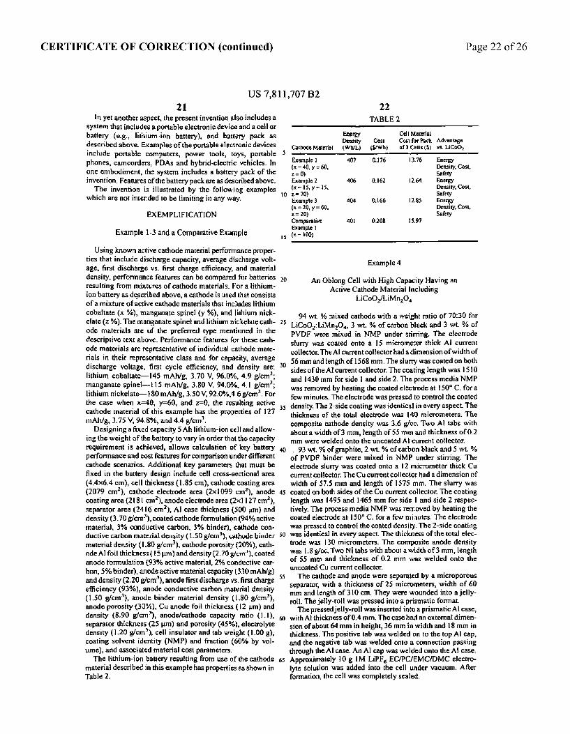
CERTIFICATE OF CORRECTION (continued) Page 22 of 26
US 7,811,707 B2 1.
in yet another aspect, the present invention also includes a Syster that includes a portable electronic device and a cellor battery (e.g., lithium-ion battery), and battery pack as described above. Examples of the portable electronic devices include portable computers, power tools, toys, portable phones, camcorders, PDAs and hybrid-electric vehicles. In one embodiment, the system includes a battery pack of the invention. Features of the battery pack are as described above. The invention is illustrated by the following examples
which are not intended to be limiting in any way.
EXEMPLIFICATION
Example 1-3 and a Comparative Example
Using known active cathode material performance proper ties that include discharge capacity, average discharge volt age, first discharge vs. first charge efficiency, and material density, performance features can be compared for batteries resulting from mixtures of cathode materials. For a lithium ion battery as described above, a cathode is used that consists of a mixture of active cathode materials that includes lithium cobatate (x %), manganate spinely 6), and lithium nick elate (za). The manganate spine and lithium nickelate cath ode materials are of the preferred type mentioned in the descriptive text above. Performance features for these cath ode materials are representative of individual cathode mate rials in their representative class and for capacity, average discharge voltage, first cycle efficiency, and density are: lithium cobaltate-145 mAh/g, 3.70 W, 96.0%, 4.9 g/cm; manganate spinel- 15 mAh/g, 3.80 V, 94.0%, 4.1 g/cm; lithium nickelate-80 mAh/g, 3.50 V, 92.0%,46g/cm. For the case when x=40, y=60, and z=0, the resulting active cathode material of this example has the properties of 127 mAh/g, 3.75 W, 94,8%, and 4.4 g/cm.
Designing a fixed capacity 5Ahithium-ion cell and allow ing the weight of the battery to way in order that the capacity requirement is achieved, allows calculation of key battery performance and cost features for comparison under different cathode scenarios, Additional key parameters that must be fixed in the battery design include cell cross-sectional area (4.4x6.4 cm), cell thickness (1.85 cm), cathode coating area (2079 cm), cathode electrode area (2x1099 cm), anode coating area (281 cm), anode electrode area (2x1127 cm), separator area (2416 cm), Al case thickness (500 um) and density (3.70 g/cm), coated cathode formulation (94% active naterial, 3% conductive carbor, 3% binder, cathode con ductive carbon material density (1.50 g/cm), cathode binder material density (1.80 g/cm), cathode porosity (20%), cath ode Alfoil thickness (15um) and density (2.70 g/cm), coated anode formulation (93% active material, 2% conductive car bon, 5% binder), anode active material capacity (330 mAh/g) and density (2.20 g/cm), anode first discharge vs. first charge efficiency (93%), anode conductive carbon material density (1.50 g/cm), anode binder material density (1.80 g/cm), anode porosity (30%), Cuanode foil thickness (12 m) and density (8.90 g/cin), anode/cathode capacity ratio (1.1), separator thickness (25m) and porosity (45%), electrolyte density (I.20 g/cm), cell insulator and tab weight (.00 g), coating solvent identity (NMP) and fraction (60% by vol une), and associated material cost parameters. The lithium-ion battery resulting fron use of the cathode
material described in this example has properties as shown in Table 2.
3.
s
25
3.
40
43
SS
22 TABLE
Energy Cell Material Density Cost Cosfor Pack Advantage
Cathod Material Wh (SWh) of Cells (S. vs. LiCo0.
Example 1 40 , 3. Energy (x = 40, y = 50, density, Cost, z = 0) Safety Example 2 40s . 2.64 Energy (x = 5, re 15. ensity, Cost, z = 0) Safety Example 3 04 O16 2.85 Energy (x = 20, y = 60 Density, Cost, z = 20) Safety Comparative 40 0.08 5.9 Exsuple l (x = 00)
Example 4
An Oblong Cell with High Capacity Having an Active Cathode Material Including
LiCoOLiMnO,
94 wit. 9% mixed cathode with a weight ratio of 70:30 for LiCoO:LiMnO, 3 wt.% of carbon black and 3 wt.% of PWDF were mixed in NMP under stirring. The electrode slurry was coated onto a 5 micrometer thick All current collector. The AI current collector had a dimension of width of 56mmand length of 1568 mm. The slurry was coated on both sides of the Acurrent collector. The coating length was 1510 and 1430 mm for side 1 and side 2. The process media NMP was removed by heating the coated electrode at 50 C. for a few minutes. The electrode was pressed to control the coated density. The 2-side coating was identical in every aspect. The thickness of the total electrode was 40 micrometers. The composite cathode density was 3.6 g/cc. Two Al tabs with about a width of 3 mm, length of 55 mm and thickness of 0.2 mm were welded onto the uncoated A current collector. 93 wt.% of graphite, 2 wt.% of carbon black and 5 wt.%
of PWDF binder were mixed in NMP under stiring. The electrode slurry was coated onto a 12 micrometer thick Cu current collector. The Cucurrent collector had a dimension of width of 57.5 Inn and length of 1575 mm. The slurry was coated on both sides of the Cu current collector. The coating length was 1495 and 1465 mm for side and side 2 respec tively. The process media NMP was removed by heating the coated electrode at 50°C, for a few minutes. The electrode was pressed to control the coated density. The 2-side coating was identical in every aspect. The thickness of the total elec trode was 30 micrometers. The composite anode density was 1.8g/cc. Two Nitabs with about a width of 3 mm, length of 55 mm and thickness of 0.2 mm was welded onto the uncoated Cu current collector. The cathode and anode were separated by a microporous
separator, with a thickness of 25 micrometers, width of 60 mm and length of 30 cm. They were wounded into a jelly roll. The jelly-roll was pressed into a prismatic format. The pressedjelly-roll was inserted into a prisinatic Alcase,
with AEthickness of O.4 mm. The case had an external dimen sion of about 64 mm in height, 36 Inn in width and l8 mm in thickness. The positive tab was welded on to the top Al cap, and the negative tab was welded onto a connection passing through the Al case. An Al cap was welded onto the A case. Approximately 10 g M LiPF EC/PC/EMCDMC electro lyte solution was added into the cell under vacuum. After formation, the cell was completely sealed.
CERTIFICATE OF CORRECTION (continued) Page 23 of 26
US 7,81 1,707 B2 23
This cell had a capacity of 44 Ahat CS discharge rate. The nominal voltage was 3.7W. The total cell weight was approxi mately 89 g. The cell energy density was approximately 83 Wh/kg and 440 Wh/liter.
Example 5A (Prophetic Example)
A Cell with an Active Cathode Material including LiCoOLiMn. Alo. O.
In this example, a prismatic cell with an active cathode material including LiCoO/LiMn. AlO is designed, This cell can be made by a similar procedure as described above in Example 4. For this example, the cathode mix includes 94 wit, % of mixed cathode with a weight ratio of 70:30 for LiCoO, LiMn. Alo, O, 3 wt.% of carbon black and 3 wt.% of PWDF. The electrode slurry is coated onto a 5 micrometer thick Al current collector, The Al current collector has a dimension of width of 56 mm and length of 193 mm. The slunty is coated on both sides of the Al current collector. The coating length is l913 and 1799mm for side landside 2. The process media NMP is removed by heating the coated elec trode at 150 C. for a few minutes. The electrode is pressed to control the porosity of 25% volurae, The 2-side coating is identical in every aspect. The thickness of the single coating layer is 50 micrometers. The composite cathode density is 3.36 g/cc. An Al tab with a width of 5mm, length of 64 mm and thickness of 0.1 run is welded onto the uncoated Al current collector.
93 wt.% of graphite, 2 wt.% of carbon black and 5 wt.% of PVDF binder is mixed in NMP under stirring. The elec trode slurry is coated onto a 2 micrometer thick Cu current collector. The Cu current collector has a dimension of width of 58mm and length of 1940 mm. The slurry is coated on both sides of the Cu current collector. The coating length is 1903 and 857 mm for side and side 2 respectively, leaving 10 mm Cu uncoated. The process media NMP is removed by heat the coated electrode at 50 C. for a few minutes. The electrode is pressed to control the porosity of 37% volume, The 2-side coating is identical in every aspect. And the thick ness of the single coating layer is 53 micrometers, The cal culated composite anode density is 1.35 g/cc. A Nitab with a width of 5mm, length of 64 mm and thickness of 0.5 mm can be welded onto the uncoated Cu current collector.
The cathode and anode are separated by a microporous separator, with a thickness of 25 micrometers, width of 60 Inn and length of 4026 mm. They are then wounded into a jelly-roll. The jelly-roll is pressed into a prismatic format. The pressedjelly-rollis inserted into a rectangular Al case,
with A thickness of O.5 rrr, The case has an external dinner sion of 64 mm in height, 44 mm in width and 17 mm in thickness, The positive tab is welded on to the top Alcap, and the negative tab is welded onto the Al case. An A cap is welded onto the A case. Approximately 12.3 g M LiPF ECEMCDMC electrolyte solution is added into the cell under vacuum. After formation, the cell is completely sealed.
This cell has a calculated capacity of 4.5 Ah at C5 dis charge rate. The calculated nominal voltage is 3.7W. The total calculated cell weight is approximately 96 g. The calculated cell energy density is approximately 174 Wh/kg and 350 WL,
5
s
3.
d
SO
SS
5
24 Example 5B (Prophetic Example)
A Cell with an Active Cathode Material including LiCoO/LiMn. Alo OLiNios.Alooscootso
In this example, a prismatic cell with an active cathode material including LiCoO/LiMntsACLiNiagAlaos CoO, is designed. This cell can be made by a similar procedure as described above in Example 4: 94 wit.% of mixed cathode with a weight ratio of 10:50:40
for LiCoO,LiMn. AllO:LiNio Alooscoo 150, 3 wt.% of carbon black and 3 wt % of PWOF are mixed in NMP under stirting. The electrode slurry is coated onto a 15 Inicroneter thick Al current collector, The Al current collec tor has a dimension of width of 56 mm and length of 93 mm. The slurry is coated on both sides of the Al current collector. The coating length is 1913 and 1799 mm for side and side 2. The process media NMP is removed by heat the coated electrode at ISO C, for a few minutes. The electrode is pressed to control the porosity of 25% volume. The 2-side coating is identical in every aspect. And the thickness of the single coating layer is 56 micrometers. The calculated com posite cathode density is 3.2 g/cc. An Al tab with a width of 5 mm, length of 64 mm and thickness of 0. mm is welded onto the uncoated Al current collector.
93 wi.% of graphite, 2 wt.% of carbon black and 5 wt % of PVDF binder are mixed in NMP under stirring. The clec trode slurry is coated onto a 12 micrometer thick Cu current collector. The Cu current collector has a dimension of width of 58mm and length of 940mm. The slurry is coated on both sides of the Cu current collector. The coating length is 1903 and E857 mm for side l and side 2 respectively, leaving 10 mn Cu uncoated. The process media NMP is retTowed by heat the coated electrode at 150 C. for a few minutes. The electrode is pressed to control the porosity of 37% volume. The 2-side coating is identical in every aspect. The thickness of the single coating layer is 60 micrometers. The calculated composite anode density is t.35 gfcc. A Nitab with a width of 5 mm, length of 64 mm and thickness of 0.5 nm is welded onto the uncoated Cu current collector. The cathode and anode are separated by a microporous
separator, with a thickness of 25 micrometers, width of 60 mm and length of 4026 mm. They are wounded into a jelly rol. The jelly-roll is then pressed into a prismatic format. The pressed jelly-roll is inserted into a rectangular Al case,
with Al thickness of O.5 mm. The case has an external dimen sion of 64 nm in height, 44 mm in width and 7 mm in thickness. The positive tab is welded on to the top Al cap, and the negative tab is welded onto the Al case. An Al cap is welded onto the A case. Approximately 2.3 g M Liff EC/EMCDMC electrolyte solution is added into the cell under vacuum. After formation, the cell is completely sealed.
This cell has a calculated capacity of 5 Ahat C/5 discharge rate. The calculated nominal voltage is 3.67W, The total cal culated cell weight is approximately Olg. The calculated cell energy density is approximately 131 Wh/kg and 362 WL.
Example 6
CeTests
The cell of Example 4 was cycled (i.e. charged and dis charged) as follows: The cell was charged with a constant current of 0.7 C to a
voltage of 4.2W and then was charged using a constant volt age of 4.2W. The constant voltage charging was ended when

CERTIFICATE OF CORRECTION (continued) Page 24 of 26
US 7,811,707 B2 25
the current reached 44 mA. After resting at the open circuit state for 30 minutes, it was discharged with a constant current of C5. The discharge ended when the cell voltage reached 2.75 V. These procedures were repeated for 3 times. Then the cell was charged with a constant current of 0.7C
to a voltage of 4.2V and then subsequently was charged using a constant voltage of4.2V. The constant voltage charging was ended when the current reached 44 mA. After resting at the open circuit state for 30 minutes, it was discharged with a constant current of l C. The discharge ended when the cell voltage reached 2.75 W. These procedures repeated continu ously to obtain cycle life data.
For rate capability testing, eight cells were charged as described about and discharge was performed to 2.75W using different current rates ranging in value from C/5 to 2 C. As a comparison example, an LG 18650 of LG in Seoul,
Korea ("LG”) and a SANYO 18650 celwerc tested with the procedures described above, Cells were typically tested at 23 C. (room temperature) and 60° C. Results of the cell tests were shown in FIGS. 6-9. As can be seen in FIGS. 6-9, a cell of the present invention showed higher voltage (FIG. 6), better cycle life at room temperature (FIG.7), better cycle life at 60°C., (FIG. 8) and better rate capability (FIG.9).
Example 7
Safety Tests for Lithium-lon Batteries including a Mixture of Lithium Cobaitate and Manganate Spinel
The safety of a lithium-ion battery, consisting of a single or multiple ceils, is generally dependent on the chemistry inter nal to the lithium-ion cell(s). In all cases, a lithium-ion cell will contain materials with some given amount of energy, that energy being capable of release through certain abuse sce narios that may cause fire or explosion from the cell. Typi cally, lithium-ion cells are designed for acceptable safety performance through one or more of the followings: (1) care ful selection of materials, (2) proper engineering design of internal cell chemicals and components, (3) incorporation of Safety devices into the cell, and (4) control electronics (i.e. pack electronics, software control) that maintain safe opera tion of cell(s). In addition, preferably, manufacturing envi ronment is carefully controlled to avoid defects and foreign particulates that may cause internal shorts, which can initiate rapid heating and thermal runaway.
Preferably, the lithium-ion cells (batteries) of the invention are designed to withstand abuse scenarios that might be encountered during their use. One reference for the abuse scenarios is the UL safety testing protocols for lithium-ion cells, UL 1642. General categories of abuse include mechani cal abuse, electronic abuse and temperature abuse. DSC Tests DSC tests were run on cathode mixtures that included
LicoO and Li. Minis Mgolo. DSC tests were also run on the individual cathode materials. For the DSC testing, the cathodes were prepared by mixing LiCoO, Li. Mr. MgO (in the designed ratios), carbon black and polyvi nylidene fluoride (93.3.5:3.5, w:w:w) in n-methyl-2-pyrroli done, The slurry was then cast on aluminuin foil and dried at 10 C. for overnight, And the coated electrode was then
calendared to the controlled thickness with a target loading density of 3.3 to 3.7 g/cc depending on the ratio of LiCoO, to the manganate spinel to ensure the same porosity for all the electrodes. Disks were then punched out of the foil. Lithium foil was used as an anode. The electrolyte was MiPF6 in a mixture of EC, PC and DEC. The coin cells made were tested at C/S for two cycles between 3.0 W and 4.3 V, then fully
O
s
O
s
3.
35
O
45
SO
s
SS
26 charged to 4.3W before DSC study. The cells were then opened in an Ar-filled glove box. The electrode materials were recovered from the aluminum foil and sealed into a gold plated stainless steelpar. The measure aents were carried out using a temperature scan rate of 5 C.Amin.
FIG. Oshows the total heat of reaction for different cath ode material samples (diamonds in FIG, 10) where the amount of the manganate spinel material was varied from 0 to 100%. This data was a measure of the chemical safety of a Li-ion cell, with lower total heat indicating increased safety. Also plotted in FIG. 10 is a theoretical prediction for the total heat based on a simple combination of the pure materials (open circles in FIG. 10). As shown in FIG. 10, the actual measured values showed unexpected enhanced improvement over the predicted value in the safety of the cells. Rate of Heat Release Tests
Anothermeasure of safety is generally the rate at which the available energy can be released. For two cathode samples with similar amounts of energy, the sample that releases heat at a slower rate would be expected to be safer. FIG. 11 shows data for a range of cathode samples with varying the amount of Li MiniMgO Based on this data, there appears to be an optimum range for safety based on maximum rate of reaction. The data shown in FIG. 1 suggested that a mixture of approximately 20-50% of Li MinisMgO, and 80-50% of LiCoO was optimat.
FIG. 12 shows data for different cathode materials used in full-sized Li-ion cells. The cathode Iaterials included a undoped manganate spinel (Li MnO) and LiCoO). The amount of an undoped Tmanganate spinel (Li MnO) was varied from 0-50%. Based on a temperature environment test of subjecting the cell to 50 C., a test that typically would result in firefexplosion of Li-ion cells, the time at 150 C. before fire/explosion was measured. The data of FIG. 12 indicates an advantage associated with the cathode sample containing from 20-50% of the manganate spinel. In these cases, the cells were able to withstand the high temperature treatment for longer time, indicating increased chemical sta bility, Cell Temperature. During Discharge
Under high loading conditions, the temperature of Li-ion cells will generally increase significantly. The maximum ten perature is typically related to the cell chemistry, and engi neering of the cells. As shown in Table 3, the maximum temperatures measured at the surface of cells of the invention, which included 70% LiCoC, and 30% of Li MnO, as the cathode materials of the cells, under different discharge rate were lower than the comparable cells with cathode of pure LiCoO, from SANYO, Japan.
TABLE 3
Maximum emperature (C.) at Discharge Rates from CS (A of a cycle) to 2C (2 cycles)
CS C3 C 1C 2C
rwention S. . 2. S. 49, Comparable cell 55 26.2 9. 3. 5.5
Example 8
Cycle Life for Lithium-ton Batteries including a Mixture of Lithium Cobaltate and Manganate Spinel
One of the important performance parameters of Li-ion cells is the capacity and the retention of the capacity (cycle

CERTIFICATE OF CORRECTION (continued) Page 25 of 26
US 7,81 1707 B2 27
life) in the service life of the cells. The cycle life was typically measured by the number of cycles when the cell capacity is 80% of the initial capacity, FIG. 13 shows that the cells of the invention with cathode of 70% LiCoO, and 30% of Li MnO, have much longer cycle life than those comparable, commercially available cells with cathode of pure LiCoO, from LG, Korea ("LG") and from SANYO, Japan ("Sanyo").
EQUIVALENTS
While this invention has been particularly shown and described with references to preferred embodiments thereof, it will be understood by those skilled in the art that various changes in form and details may be made therein without departing from the scope of the invention encompassed by the appended claims.
What is claimed is: i. A lithium-ion battery having a cathode that includes an
active cathode material, the active cathode materia compris ing a cathode Enixture that includes:
a) a lithium cobaltate; and b) a manganate spinel represented by an empirical formula
of Li a (Mn- A2)-2O. where; xl and x2 are each independently equal to or greater than
0.01 and equal to or less than 0.3; yl and y2 are each independently equal to or greater than
0.0 and equal to or less than 0.3; zl is equal to or greater than 3.9 and equal to or less than
4.), and A' is at least one member of the group consisting of
magnesium, aluminum, cobalt, nickel and chromium, wherein the lithium cobaltate and the manganate spinel are
in a weight ratio offithium cobaltate:manganate spinel between about 0.95:0.05 to about 0.55:0.45.
2. The lithium-ion battery of claim 1, wherein the Eithium cobaltate and Tanganate spinei are in a weight ratio of lithium cobaltate:manganate spinel between about 0.9:0. to abour 0.6:0.4.
3. The lithium-ion battery of claim 2, wherein the lithium cobaltate and manganate spinel are in a weight ratio of lithium cobaltate:Inanganate spinel between about 0.8:0.2 to about 0.6:0.4.
4. The lithium-ion battery of claim 1, wherein the cathode material includes a modified lithium cobaltate: that is modi fied with at least one modifier selected from the group con sisting of a lithium modifier and a cobalt modifier of the lithium cobaltate, and wherein the lithium modifier is at least one member of the group consisting of magnesium (Mg) and sodium (Na), and wherein the cobalt modifier is at least one member of the group consisting of manganese (Mn), alumi num (Al), boron (B), titanium (Ti), magnesium (Mg), calcuin (Ca) and strontium (Sr).
5. The lithium-ion battery of claim 4, wherein at least one of the modifiers of lithium is magnesium,
6. The lithium-ion battery of claim 1, wherein the lithium cobaltate is LiCoO.
7. The lithium-ion battery of claim 6, wherein the lithiurn cobattate is liCoO coated with ZrO, or Al(PO).
8. The lithium-ion battery of clair. 1, wherein the manga nate spinel is Li. MinisMigo.oO.
9. The lithium-ion battery of claim 1, wherein the manga nate spinel is LiMnO.
10. The Eithium-ion battery of claim 9, wherein the Eithium cobaltate and manganate spinel are in a weight ratio of lithium cobatate:Tanganate spinel between about 08:0.2 to about 0.6:0.4.
O
s
O
s
45
SO
SS
ES
28 1. The lithium-ion battery of claim 1, wherein the lithium
ion battery has a capacity greater than about 3.0 Ahlcell. 12. The lithium-ion battery of claim 1, wherein the
lithium-ion battery has a capacity greater than about 4.0 Ahfice.
13. A lithium-ion battery having a cathode that includes an active cathode material, the active cathode material compris ing a cathode mixture that includes:
a) LiCoO, and b) LiMnO, where, x is equal to or greater than 0.01 and equal to or less
than 0.3; and zi is equal to or greater than 3.9 and equal to or less than
4.l., wherein LiCo0, and LiMnO, are in a weight ratio of lithium cobatate:manganate spinel between about 0.75:0.25 to about 0.65:0.45.
14. The lithium-ion battery of claim 13, wherein the LiCoO, is coated with ZrO, or ACPO).
15. The lithium-ion battery of claim 13, whicrcin the battery has a prismatic cross-sectional shape.
16. The lithium-ion battery of claim 15, wherein the battery has an oblong Cross-sectional shape.
17. The lithium-ion battery of claim 3, wherein the lithium-ion battery has a capacity greater than about 3.0 Ahfice.
18. A method offorting a lithium-ion battery, comprising: a) forming an active cathode material including a cathode
mixture that includes: i) a lithium cobaltate; and ii) a manganate spinel represented by an empirical for mula of Li (Mi-Az)-O where:
xl and x2 are each independently equal to or greater than 0.01 and equal to or less than 0.3,
y! and y2 are each independently equal to or greater than 0.0 and equal to or less than 0.3;
z is equal to or greater than 3.9 and equal to or less than 4. and
A' is at least one member of the group consisting of magnesium, aluminum, cobalt, nickel and chromiurn,
wherein the lithiun cobaltate and the manganate spinel are in a weight ratio of lithium cobaltate:manganate spinel between about 0.95:0.05 to about 0.55:0.45;
b) forming a cathode electrode with the active cathode material; and
c) forming an anode electrode in electrical contact with the cathode via an electrolyte, thereby forming a lithium-ion battery.
19. The method of claim: 18, wherein the lithium-ion bat tery is formed to have a capacity greater than about 3.0 Ahcell.
20. The method of clair 9, wherein the lithium-ion bat tery is formed to have a capacity greater than about 4.0 Ah/cell.
21. A battery pack comprising a plurality of cells, wherein each of the ceils includes an active cathode II laterial including a cathode mixture that includes:
a) a tithium cobaltatic; and b) a ranganate spine represented by an empirical fortula
of Li (Mn-1A2)-2O, where: xi and x2 are each independently equal to or greater than
0.04 and equal to or less than 0.3; y1 and y2 are eachindependently equal to or greater than
0.0 and equal to or less than 0.3; z is equal to or greater than 39 and equal to or less than
4, and

CERTIFICATE OF CORRECTION (continued) Page 26 of 26
US 7,811,707 B2 29 30
A' is at least one member of the group consisting of 25. The battery pack of claim 21, wherein at least one cell magnesium, aluminum, cobalt, nickel and chromium, a prismatic cross-sectional shape,
wherein the lithium cobaltate and the manganate spinel are 26. The battery pack of claim 25, wherein the prismatic . - cross-sectional shape is an oblong shape. ESSEE assignate ificately pack of claii, wherein the lithium
cobaltate is LiCoO and the manganate spine is li 22. The battery pack of claim 21, wherein the capacity of MnO.
the cells is equal to or greater than about 3.3 Ah/cell. 28. The battery pack of clairn 27, wherein the lithium 23. The battery pack of claim 21, wherein the internal cobaltate and the manganate spinel are in a weight ratio of
impedance of the cells is less than about 50 milliohms. lithium cobaltate:Inanganate spinel between about 0.8.0.2 to 24. The battery pack of claim 21, wherein the cells are in " 0.6:0.4.
series and no cells are connected in parallel. :