12 TON HYDRAULIC INSTALLING TOOL FOR COLOR … · 2018-04-16 · Pint Oil Hydraulic Mil-H-5606A (2...
4
12 TON HYDRAULIC INSTALLING TOOL FOR COLOR-KEYED ® and STA-KON ® CONNECTORS INSTRUCTION SHEET (Catalog Number: 13642M) IMPORTANT: Read and understand all of the instructions and safety information in this manual before operating or servicing this tool. TA01635 C Page 1 of 4 Table of Contents Page 1.0 GENERAL INFORMATION ...................... 2 WARNING NOTE ........................................... 2 1.1 Description .............................................. 2 1.2 Specifications .......................................... 2 2.0 INSTRUCTIONS ...................................... 2 2.1 To Install Dies .......................................... 2 2.2 Typical Crimping Procedure .................... 3 2.3 Field Service ............................................ 3 2.4 Available Dies .......................................... 4
Transcript of 12 TON HYDRAULIC INSTALLING TOOL FOR COLOR … · 2018-04-16 · Pint Oil Hydraulic Mil-H-5606A (2...

12 TON HYDRAULIC INSTALLING TOOLFOR COLOR-KEYED® and STA-KON® CONNECTORS
INSTRUCTION SHEET (Catalog Number: 13642M)
IMPORTANT: Read and understand all of the instructions and safetyinformation in this manual before operating or servicing this tool.
TA01635 CPage 1 of 4
Table of ContentsPage
1.0 GENERAL INFORMATION ...................... 2WARNING NOTE ........................................... 21.1 Description .............................................. 21.2 Speci�cations.......................................... 2
2.0 INSTRUCTIONS ...................................... 22.1 To Install Dies .......................................... 22.2 Typical Crimping Procedure .................... 32.3 Field Service............................................ 32.4 Available Dies .......................................... 4
TA01635 CPage 2 of 4
Yoke Cap
Rotate
Rotate
GuardOpen
Yoke
Ram
Locking Pin
FIGURE 1
FIGURE 2
FIGURE 3 FIGURE 4
Ram
Die Half
Yoke
CloseGuard
NotchesEngage
InsertLocking
PinDie Half
with Plate
Yoke Cap
Yoke
51 2 43
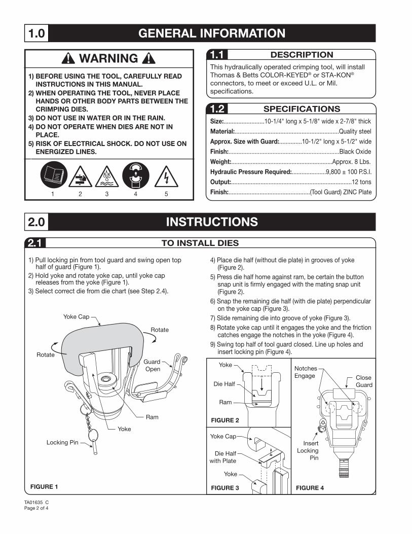
1.0 GENERAL INFORMATION
DESCRIPTION1.1This hydraulically operated crimping tool, will install Thomas & Betts COLOR-KEYED® or STA-KON® connectors, to meet or exceed U.L. or Mil. speci�cations.
SPECIFICATIONS1.2Size:.........................10-1/4" long x 5-1/8" wide x 2-7/8" thick
Material:................................................................Quality steel
Approx. Size with Guard:..............10-1/2" long x 5-1/2" wide
Finish:....................................................................Black Oxide
Weight:..............................................................Approx. 8 Lbs.
Hydraulic Pressure Required:.....................9,800 ± 100 P.S.I.
Output:..........................................................................12 tons
Finish:..................................................(Tool Guard) ZINC Plate
INSTRUCTIONS2.0
TO INSTALL DIES
1) Pull locking pin from tool guard and swing open top half of guard (Figure 1).
2) Hold yoke and rotate yoke cap, until yoke cap releases from the yoke (Figure 1).
3) Select correct die from die chart (see Step 2.4).
4) Place die half (without die plate) in grooves of yoke (Figure 2).
5) Press die half home against ram, be certain the button snap unit is �rmly engaged with the mating snap unit (Figure 2).
6) Snap the remaining die half (with die plate) perpendicular on the yoke cap (Figure 3).
7) Slide remaining die into groove of yoke (Figure 3).8) Rotate yoke cap until it engages the yoke and the friction
catches engage the notches in the yoke (Figure 4).9) Swing top half of tool guard closed. Line up holes and
insert locking pin (Figure 4).
2.1
1) BEFORE USING THE TOOL, CAREFULLY READ INSTRUCTIONS IN THIS MANUAL.
2) WHEN OPERATING THE TOOL, NEVER PLACE HANDS OR OTHER BODY PARTS BETWEEN THE CRIMPING DIES.
3) DO NOT USE IN WATER OR IN THE RAIN.4) DO NOT OPERATE WHEN DIES ARE NOT IN
PLACE.5) RISK OF ELECTRICAL SHOCK. DO NOT USE ON
ENERGIZED LINES.
WARNING

TA01635 CPage 3 of 4
FIGURE 5
TerminalStop and Locator
Ram
Bottom Die
Cable
Yoke Cap Top Die withDie Plate
Guard
1) Select terminal to be attached to the wire and insert stripped wire into barrel of terminal.
2) Place terminal, with wire inserted, in the movable die and push terminal up against the terminal locator (if available) and crimp (see Figure 5).NOTE: The COLOR-KEYED® connectors have color bands to show the position and number of crimps. In addition, the dies have engraved code numbers to match code numbers printed on the COLOR-KEYED® connectors.
TYPICAL CRIMPING PROCEDURE2.2
PINCH POINT! KEEP FINGERS CLEAR OF DIE AREA WHEN OPERATING TOOL.DO NOT OPERATE TOOL WITHOUT GUARD IN PROPER LOCKED POSITION.
CAUTION
CAUTIONNEVER OPERATE THIS TOOL WITHOUT THE GUARD IN PROPER LOCKED POSITION, AND WITHOUT A DIE SET IN THE TOOL AND THE CAP IN PLACE. WHEN OPERATING TOOL, ALWAYS KEEP MALE AND FEMALE PROTECTIVE CAPS COUPLED TOGETHER, TO KEEP HYDRAULIC SYSTEM FREE OF DIRT.
FIGURE 6
These are precision tools and must be handled accordingly. Therefore, all maintenance must be performed by quali�ed personnel only.
NOTES:1) Do not use on hardened objects such as steel.2) Do not use tool without guard in proper locked position.3) Repair Kit Catalog Number 11025 contains replacement
parts -7,-8,-10,-12,-14,-15,-16-and 19.4) Dies ordered separately.5) Travel .6875 inches displacement 1.7738 Cu. In. (0.0614
Pint Oil Hydraulic Mil-H-5606A (2 Cu. In.).6) Maximum oil pressure 10,000 P.S.I.
FIELD SERVICE2.3
25
26
17
731
34
20
6
19
10
21
12
8
1
2
29
7
8
4
28
30
5
15 1314
16
OR
AS ALTERNATE SECTION A-A
A
A
3332
ITEM NO.
SPARE PART NO.
FORMER DESIGNATION*
REQ’D PER UNIT
DESCRIPTION
1 R014501 13642-1 2 Friction—Catch
2 R206703 — 1 Cap, Yoke4 R205701 13642-4 1 Ram5 R002101 13642-5 1 Retaining Ring6 R205801 13642-6 1 Rod, Spring
7 R205901 13642-7 2 Button Unit, Snap, Female
8 R014402 13642-8 2 Screw10 R002201 13642-10 1 “O” Ring Packing12 R206001 13642-12 1 Screen13 R206101 13642-13 1 Plug, Retaining14 R002301 13642-14 1 Steel Ball15 R002901 13642-15 1 “O” Ring Gasket16 R002401 13642-16 1 Ring, Back-up17 R004814 13642-17 1 Set Screw. Socket19 R206201 13642-19 1 Ring, Back-up20 R206301 13642-20 1 Spring Compression21 R206401 13642-21 1 Support, Spring25 R206501 13642-25 1 Nameplate26 R000101 13642-26 4 Drive Screw, Nameplate27 R004815 13642-27 1 Screw, Set, Dog Point28 R003204 13642-28 1 Nut, Lock29 R206601 13642-29 1 Yoke, Head30 R206803 — 1 Cylinder
31 R017301 13691 1Bottom Snap Male (for 13642M Only) Replaces Item No’s. 7 & 8 in Yoke Cap
32 R228801 13599 1Hydraulic Coupler Assembly (Female) Blackhawk
33 R210903 13799 1Hydraulic Coupler Assembly (Female) Pioneer
34 255R001 — 1 Tool Guard— 297-15878 — 1 Steel Carrying Case
* Former designation of spare parts. Use spare part number when ordering.
For Parts or Service, contact the Tool Service Center at 1-800-284-TOOL (8665).

DIE CAT. NO.
WIRE RANGEINSTALLS TERMINAL
TYPEGAGING
11733 8 AWG D (Code) .222 / .234
11734 6 AWG E (Code) .282/ .294
11735 4 AWG F (Code) .326 / .337
11736 2, 1 AWG G (Code) .369 / .383
11737 1/0 AWG H (Code) .409 / .423
11738 2/0 AWG J (Code) .445 / .459
11739 3/0 AWG K (Code) .494 / .506
11770 4/0 AWG L (Code) .585 / .591
11771 250 MCM M (Code) .613 / .631
11781M 8 AN D (Aircraft) .208 / .212
11782M 6 AN E (Aircraft) .238 / .242
11783M 4 AN F (Aircraft) .297 / .301
11784M 2 AN G (Aircraft) .375 / .379
11785M 1 AN H (Aircraft) .415 / .419
11786M 1/0 AN J (Aircraft) .454 / .458
11787M 2/0 AN K (Aircraft) .498 / .502
11788M 3/0 AN L (Aircraft) .560 / .564
11789M 4/0 AN M (Aircraft) .616 / .620
13643 8 AWG D (Code) Nest .153 / .161
13644 6 AWG E (Code) Nest .183 / .191
13645 4 AWG F (Code) Nest .214 / .222
136508,6,4 AWG D, E, F (Indentor) —
2 to 4/0 AWG G to M (Indentor) —
13651 8 AN D (Aircraft) Nest .111 / .119
13652 6 AN E (Aircraft) Nest .151 / .159
13653 4 AN F (Aircraft) Nest .163 / .171
13654 2, 1 AWG / 2N G (Air. and Code) Nest .202 / .210
13655 1/0 AWG / 1 AN H (Air. and Code) Nest .230 / .238
13656 2/0 AWG / 1/0 AN J (Air. and Code) Nest .268 / .276
13657 3/0 AWG / 2/0 AN K (Air. and Code) Nest .246 / .254
13658 4/0 AWG / 3/0 AN L (Air. and Code) Nest .262 / .270
13659 250 MCM / 4/0 AN M (Air. and Code) Nest .308 / .316
21607 8 AWG RD (Code) .250 / .254
21608 6 AWG RE (Code) .272 / .276
21609 4 AWG RF (Code) .288 / .292
21610 1, 2AWG RG (Code) .337 / .341
21611 1/0 AWG RH (Code) .368 / .372
21612 2/0 AWG RJ (Code) .402 / .406
21613 3/0 AWG RK (Code) .436 / .440
21614 4/0 AWG RL (Code) .471 / .475
21615 250 MCM RM (Code) .519 / .523
21707 8 AN RD (Aircraft) .168 / .172
21708 6 AN RE (Aircraft) .200 / .204
21709 4 AN RF (Aircraft) .252 / .256
21710 2 AN RG (Aircraft) .310 / .314
21711M 1 AN RH (Aircraft) .337 / .341
21712 1/0 AN RJ (Aircraft) .368 / .372
21713 2/0 AN RK (Aircraft) .402 / .406
21714M 3/0 AN RL (Aircraft) .436 / .440
21715 4/0 AN RM (Aircraft) .471 / .475
21731 8, 6, 4 AN D, E, F, (Indentor Only) —
21732 2 to 250 MCM G to M (indentor Only) —
21733 8 AWG / 8 AN D Flag Terminals .147 / .153
21734 6 AWG / 6 AN E Flag Terminals .171 / .177
21735 4 AWG / 4 AN F Flag Terminals .194 / .200
21736 2, 1 AWG / 2 AN G Flag Terminals .262 / .269
21737 1/0 AWG / 1 AN H Flag Terminals .278 / .284
21738 2/0 AWG / 1/0 AN J Flag Terminals .309 / .315
21739 3/0 AWG / 2/0 AN K Flag Terminals .356 / .362
21740 4/0 AWG / 3/0 AN L Flag Terminals .382 / .388
21741 250 MCM / 4/0 AN M Flag Terminals .434 / .440
TYPE OF CRIMPS
Hex
Hex
Hex
Hex
Hex
Hex
Hex
Hex
Hex
Hex
Hex
Hex
Hex
Hex
Hex
Hex
Hex
Hex
Indented
Indented
Indented
Indented
Indented
Indented
Indented
Indented
Indented
Indented
Indented
Indented
Indented
Indented
Elliptical
Elliptical
Elliptical
Elliptical
Elliptical
Elliptical
Elliptical
Elliptical
Elliptical
Elliptical
Elliptical
Elliptical
Elliptical
Elliptical
Elliptical
Elliptical
Elliptical
Elliptical
Indented
Indented
Indented
Indented
Indented
Indented
Indented
Indented
Indented
Indented
Indented
DIE CAT. NO. COLOR CODE
WIRE RANGE*AL. CU.
DIE NO. orGAGING
11732 12-10 AWG 8 21 Red .191 / .207
11733 8 6 24 Blue .222 / .234
11734 6 4 29 Grey .282 / .294
11735 — 2 33 Brown .326 / .337
11736 4 1 37 Green .369 / .383
11737 2 1/0 42 Pink .409 / .423
11738 1 2/0 45 Gold/Black .445 /.459
11739 1/0 3/0 50 Tan/Orange .494 / .506
11740 2/0 4/0 54 Olive/Purple .535 / .553
11741 3/0 — 60 Ruby .587 / .605
11771 — 250 MCM 62 Yellow .613 / .631
11742 4/0 300 MCM 66H White .657 / .675
11743 250 MCM 350 MCM 71H Red .707 / .725
11744 300 MCM 400 MCM 76 Blue .751 / .769
11746-TB 350 MCM 500 MCM 87H Brown .861 / .879
11747-TB 400 MCM 600 MCM 94H Green .935 / .953
11748 500 MCM 700 MCM 99H Pink .979 / .997
11749 600 MCM 750 MCM 106H Black 1.049 / 1.071
11750 — 800 MCM 107H Orange 1.064 / 1.076
11751 700 MCM — 112H Purple 1.118 / 1.131
11753 750 MCM 900 MCM 115 Yellow 1.141 / 1.163
11761M 8 — — .283 / .293
11762M 6 — — .327 / .337
11763M 4 — — .395 / .405
11764M 2 — — .495 / .505
11765M 1 — — .515 / .525
11766M 1/0 — — .539 / .549
11767 2/0 — — .618 / .628
11768M 3/0 — — .651 / .661
11769 4/0 — — .737 / .747
11780 See Connector — Green .832 / .852
11790 Chart — Blue 1.110 / 1.130
STA-KON® DIES AVAILABLE COLOR-KEYED® DIES AVAILABLE
TA01635 CPage 4 of 4© 2014 Thomas & Betts. All Rights Reserved.
Thomas & Betts CorporationMemphis, Tennessee.
www.tnb.com
NOTE: To order the military version of the 13642, add an “M” suffix. EXAMPLE: 13642M, and suffix the die indentor catalog number with an “M”. EXAMPLE: 21731M, die nest catalog number does not change.
*EXCEPTION — Consult installation instruction sheets for connector Cat. No. Series 61900, 6110, 61300.
WARRANTY: Thomas & Betts sells this product with the understanding that the user will perform all necessary tests to determine the suitability of this product for the user's intended application. Thomas & Betts warrants that this product will be free from defects in materials or workmanship for a period of two (2) years following the date of purchase. Upon prompt noti�cation of any warranted defect, Thomas & Betts will, at its option, repair or replace the defective product. Misuse, misapplication or modi�cation of Thomas & Betts Products immediately voids all warranties.
Limitations and Exclusions: THE ABOVE WARRANTY IS THE SOLE WARRANTY CONCERNING THIS PRODUCT, AND IS IN LIEU OF ALL OTHER WARRANTIES EXPRESS OR IMPLIED, INCLUDING BUT NOT LIMITED TO ANY IMPLIED WARRANTY OF MERCHANTABILITY OR FITNESS FOR A PARTICULAR PURPOSE, WHICH ARE SPECIFICALLY DISCLAIMED. LIABILITY FOR BREACH OF THE ABOVE WARRANTY IS LIMITED TO COST OF REPAIR OR REPLACEMENT OF THE PRODUCT, AND UNDER NO CIRCUMSTANCES WILL THOMAS & BETTS BE LIABLE FOR ANY INDIRECT, SPECIAL, INCIDENTAL OR CONSEQUENTIAL DAMAGES.
AVAILABLE DIES2.4