12- Monochrome Display
59
Service Source K Macintosh 12 Monochrome Display
-
Upload
sergio-diaz-pereira -
Category
Documents
-
view
244 -
download
0
Transcript of 12- Monochrome Display
8/16/2019 12- Monochrome Display
http://slidepdf.com/reader/full/12-monochrome-display 1/58
Service SourceK
Macintosh 12 Monochrome
Display
8/16/2019 12- Monochrome Display
http://slidepdf.com/reader/full/12-monochrome-display 2/58
Service SourceK
Specifications
Macintosh 12" MonochromeDisplay
8/16/2019 12- Monochrome Display
http://slidepdf.com/reader/full/12-monochrome-display 3/58
Specifications Characteristics - 1
Characteristics
Picture Tube 12-in. diagonal screen
Combination phosphor EIA Type P104 and P193 (white),
provides “page-white” phospor screenHigh-contrast, anitglare surface; dark glass
Screen Resolution 640x480; 76 dpi
Displays up to 256 grays simultaneously
Scan Rates Vertical refresh rate: 66.75 Hz
Horizontal scan rate: 35.0 kHz
Rise and fall time: 16 ns maximum
8/16/2019 12- Monochrome Display
http://slidepdf.com/reader/full/12-monochrome-display 4/58
Specifications Characteristics - 2
Active Video
Display Area
8.35 in. by 6.26 in. (212 mm by 159 mm)
Input Signal Video: analog; RS-343 standard
8/16/2019 12- Monochrome Display
http://slidepdf.com/reader/full/12-monochrome-display 5/58
Specifications Controls - 3
Controls
User Controls Rear panel: power switch
Right side: brightness and contrast controls
8/16/2019 12- Monochrome Display
http://slidepdf.com/reader/full/12-monochrome-display 6/58
Specifications Physical and Electrical - 4
Physical and Electrical
Power Supply Universal power supply
Voltage: 90–132 and 190–270 VAC
Frequency: 47–63 Hz
Power: 30 W maximum
Size and Weight Height: 12.2 in. (310 mm)
Width: 14.4 in. (365 mm)
Depth: 10.2 in. (259 mm)
Weight: 16 lb. (7.3 kg)
8/16/2019 12- Monochrome Display
http://slidepdf.com/reader/full/12-monochrome-display 7/58
Specifications Operating Environment - 5
Operating Environment
Temperature 50°F–104°F (10°C–40°C)
Humidity 95% maximum, noncondensing
Altitude 10,000 ft. (3,048 m) maximum
8/16/2019 12- Monochrome Display
http://slidepdf.com/reader/full/12-monochrome-display 8/58
Service SourceK
Troubleshooting
Macintosh 12" MonochromeDisplay
8/16/2019 12- Monochrome Display
http://slidepdf.com/reader/full/12-monochrome-display 9/58
Troubleshooting General/ - 1
General
The Symptom Charts included in this chapter will help you
diagnose specific symptoms related to your product. Because cures
are listed on the charts in the order of most likely solution, try
the first cure first. Verify whether or not the product continues toexhibit the symptom. If the symptom persists, try the next cure.
(Note: If you have replaced a module, reinstall the original module
before you proceed to the next cure.)
If you are not sure what the problem is, or if the Symptom Charts
do not resolve the problem, refer to the Flowchart for the product
family.
For additional assistance, contact Apple Technical Support.
8/16/2019 12- Monochrome Display
http://slidepdf.com/reader/full/12-monochrome-display 10/58
Troubleshooting Symptom Charts/No Raster - 2
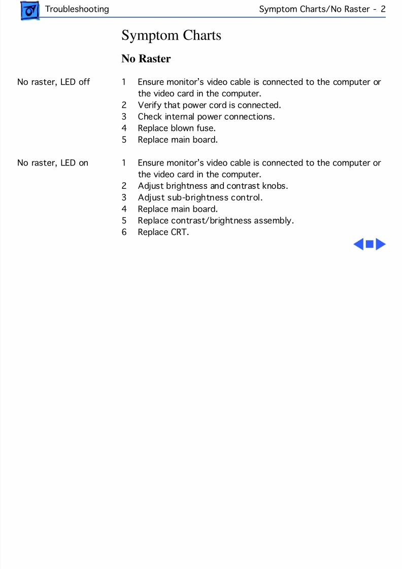
Symptom Charts
No Raster
No raster, LED off 1 Ensure monitor’s video cable is connected to the computer or
the video card in the computer.2 Verify that power cord is connected.
3 Check internal power connections.
4 Replace blown fuse.
5 Replace main board.
No raster, LED on 1 Ensure monitor’s video cable is connected to the computer or
the video card in the computer.
2 Adjust brightness and contrast knobs.3 Adjust sub-brightness control.
4 Replace main board.
5 Replace contrast/brightness assembly.
6 Replace CRT.
8/16/2019 12- Monochrome Display
http://slidepdf.com/reader/full/12-monochrome-display 11/58
Troubleshooting Symptom Charts/Geometry - 3
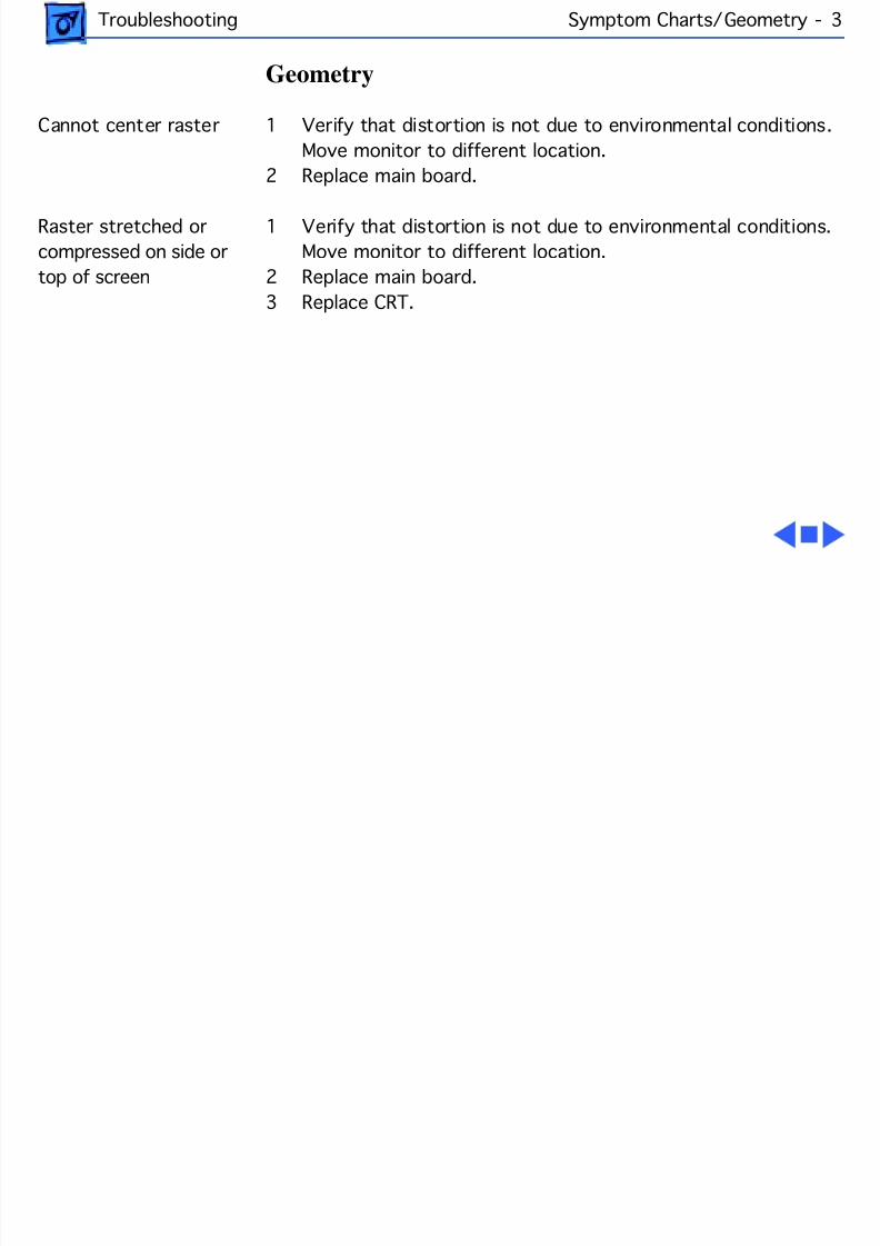
Geometry
Cannot center raster 1 Verify that distortion is not due to environmental conditions.
Move monitor to different location.
2 Replace main board.
Raster stretched or
compressed on side or
top of screen
1 Verify that distortion is not due to environmental conditions.
Move monitor to different location.
2 Replace main board.
3 Replace CRT.
8/16/2019 12- Monochrome Display
http://slidepdf.com/reader/full/12-monochrome-display 12/58
Troubleshooting Symptom Charts/Synchronization - 4
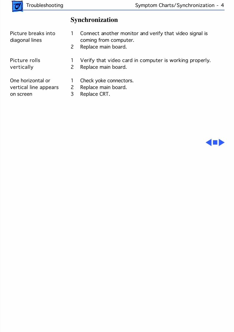
Synchronization
Picture breaks into
diagonal lines
1 Connect another monitor and verify that video signal is
coming from computer.
2 Replace main board.
Picture rolls
vertically
1 Verify that video card in computer is working properly.
2 Replace main board.
One horizontal or
vertical line appears
on screen
1 Check yoke connectors.
2 Replace main board.
3 Replace CRT.
8/16/2019 12- Monochrome Display
http://slidepdf.com/reader/full/12-monochrome-display 13/58
Troubleshooting Symptom Charts/Video - 5
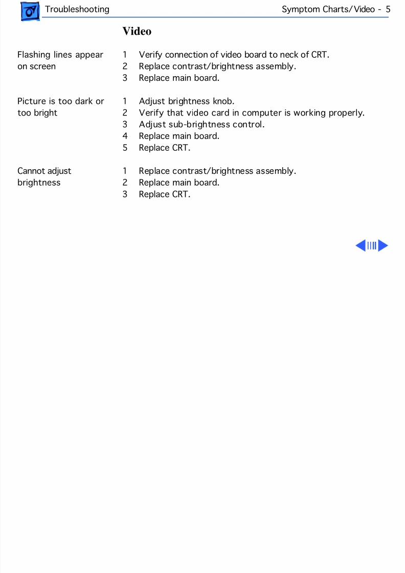
Video
Flashing lines appear
on screen
1 Verify connection of video board to neck of CRT.
2 Replace contrast/brightness assembly.
3 Replace main board.
Picture is too dark or
too bright
1 Adjust brightness knob.
2 Verify that video card in computer is working properly.
3 Adjust sub-brightness control.
4 Replace main board.
5 Replace CRT.
Cannot adjust
brightness
1 Replace contrast/brightness assembly.
2 Replace main board.
3 Replace CRT.
8/16/2019 12- Monochrome Display
http://slidepdf.com/reader/full/12-monochrome-display 14/58
Troubleshooting Symptom Charts/Video (Continued) - 6
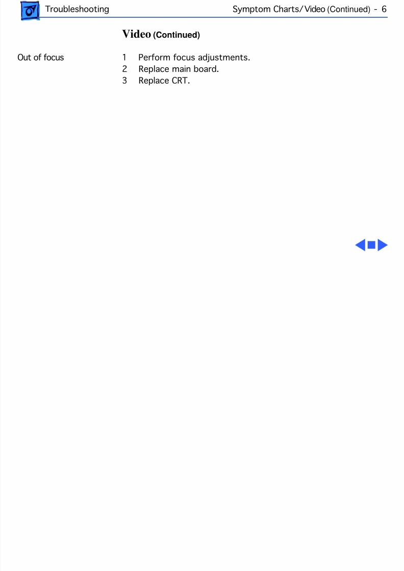
Video (Continued)
Out of focus 1 Perform focus adjustments.
2 Replace main board.
3 Replace CRT.
8/16/2019 12- Monochrome Display
http://slidepdf.com/reader/full/12-monochrome-display 15/58
Troubleshooting Symptom Charts/Miscellaneous - 7
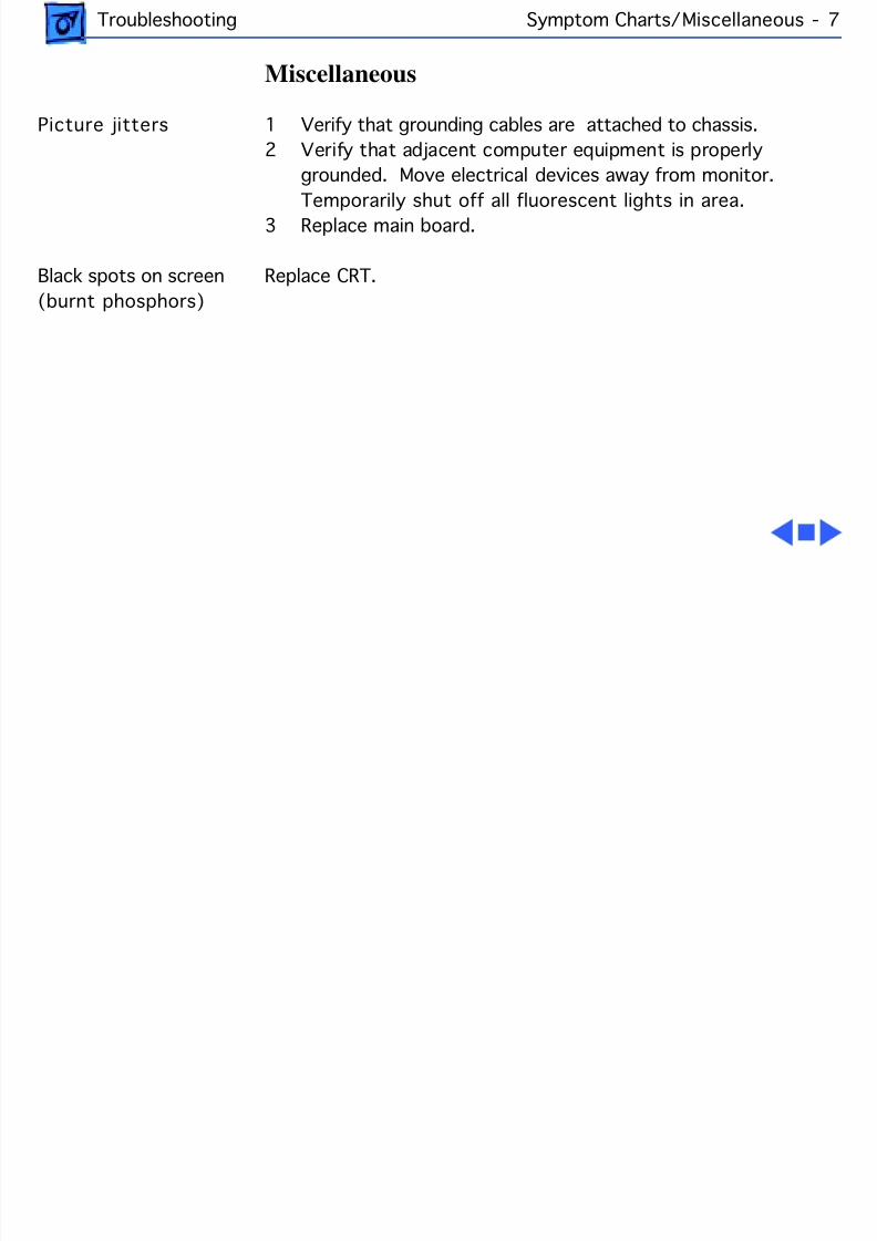
Miscellaneous
Picture jitters 1 Verify that grounding cables are attached to chassis.
2 Verify that adjacent computer equipment is properly
grounded. Move electrical devices away from monitor.
Temporarily shut off all fluorescent lights in area.3 Replace main board.
Black spots on screen
(burnt phosphors)
Replace CRT.
8/16/2019 12- Monochrome Display
http://slidepdf.com/reader/full/12-monochrome-display 16/58
Service SourceK
Take Apart
Macintosh 12" MonochromeDisplay
8/16/2019 12- Monochrome Display
http://slidepdf.com/reader/full/12-monochrome-display 17/58
Take Apart Rear Cover - 1
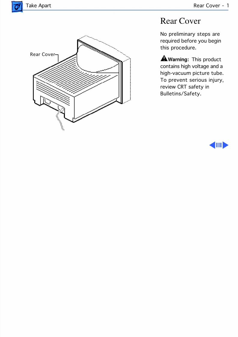
Rear Cover
No preliminary steps are
required before you begin
this procedure.
±Warning: This product
contains high voltage and a
high-vacuum picture tube.
To prevent serious injury,
review CRT safety in
Bulletins/Safety.
Rear Cover
8/16/2019 12- Monochrome Display
http://slidepdf.com/reader/full/12-monochrome-display 18/58
Take Apart Rear Cover - 2
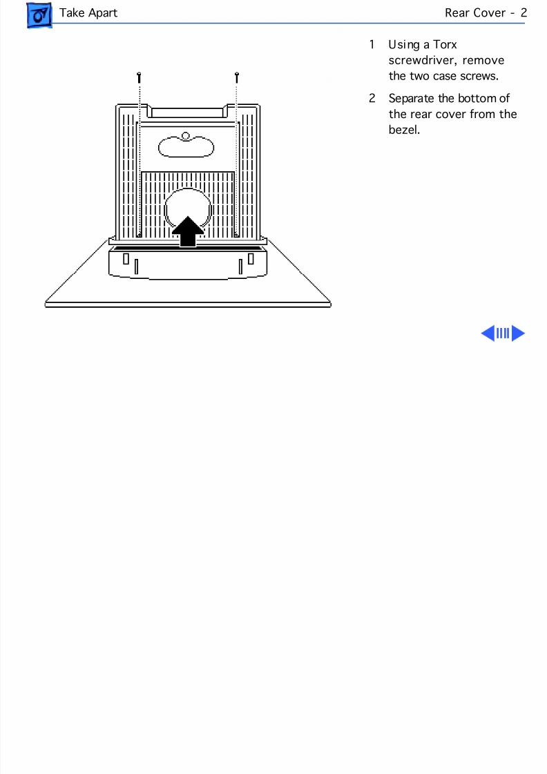
1 Using a Torx
screwdriver, remove
the two case screws.
2 Separate the bottom of
the rear cover from the
bezel.
8/16/2019 12- Monochrome Display
http://slidepdf.com/reader/full/12-monochrome-display 19/58
Take Apart Rear Cover - 3
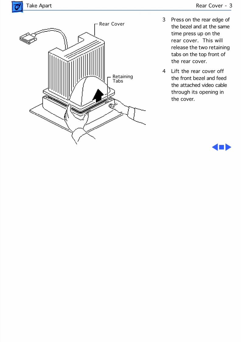
3 Press on the rear edge of
the bezel and at the same
time press up on the
rear cover. This will
release the two retaining
tabs on the top front ofthe rear cover.
4 Lift the rear cover off
the front bezel and feed
the attached video cable
through its opening in
the cover.
Rear Cover
Retaining Tabs
8/16/2019 12- Monochrome Display
http://slidepdf.com/reader/full/12-monochrome-display 20/58
Take Apart Main Board - 4
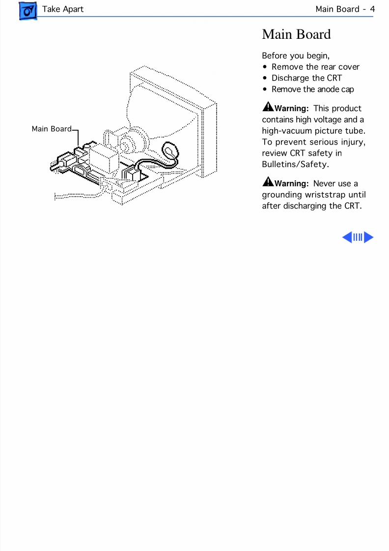
Main Board
Before you begin,
• Remove the rear cover
• Discharge the CRT
• Remove the anode cap
±Warning: This product
contains high voltage and a
high-vacuum picture tube.
To prevent serious injury,
review CRT safety in
Bulletins/Safety.
±Warning: Never use agrounding wriststrap until
after discharging the CRT.
Main Board
8/16/2019 12- Monochrome Display
http://slidepdf.com/reader/full/12-monochrome-display 21/58
Take Apart Main Board - 5
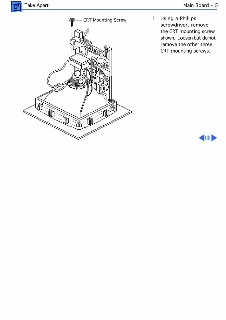
1 Using a Phillips
screwdriver, remove
the CRT mounting screw
shown. Loosen but do not
remove the other three
CRT mounting screws.
CRT Mounting Screw
8/16/2019 12- Monochrome Display
http://slidepdf.com/reader/full/12-monochrome-display 22/58
Take Apart Main Board - 6
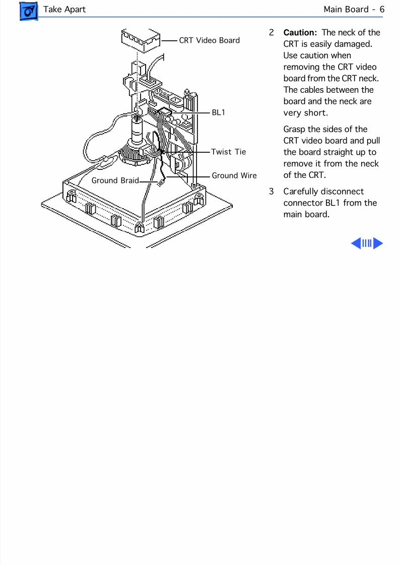
2 Caution: The neck of the
CRT is easily damaged.
Use caution when
removing the CRT video
board from the CRT neck.
The cables between theboard and the neck are
very short.
Grasp the sides of the
CRT video board and pull
the board straight up to
remove it from the neck
of the CRT.
3 Carefully disconnect
connector BL1 from the
main board.
CRT Video Board
BL1
Twist Tie
Ground WireGround Braid
8/16/2019 12- Monochrome Display
http://slidepdf.com/reader/full/12-monochrome-display 23/58
Take Apart Main Board - 7
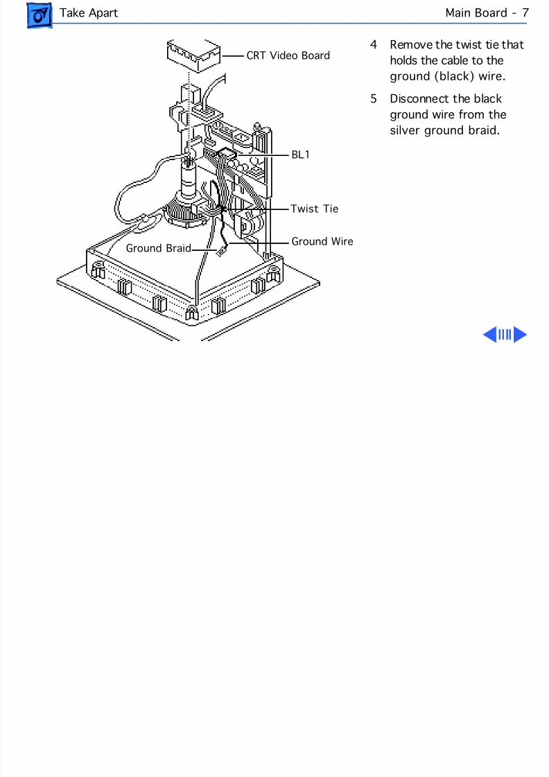
4 Remove the twist tie that
holds the cable to the
ground (black) wire.
5 Disconnect the black
ground wire from the
silver ground braid.
CRT Video Board
BL1
Twist Tie
Ground WireGround Braid
8/16/2019 12- Monochrome Display
http://slidepdf.com/reader/full/12-monochrome-display 24/58
Take Apart Main Board - 8
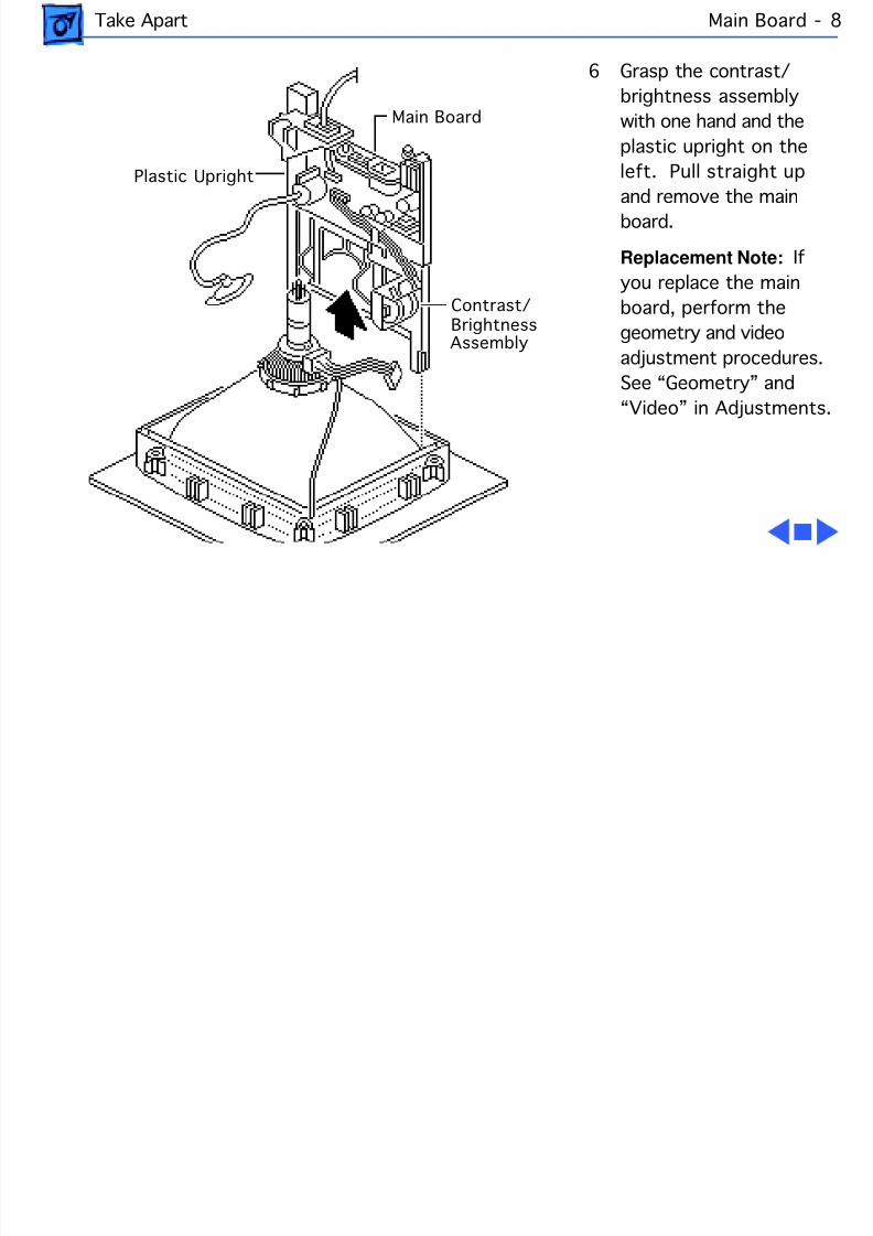
6 Grasp the contrast/
brightness assembly
with one hand and the
plastic upright on the
left. Pull straight up
and remove the mainboard.
Replacement Note: If
you replace the main
board, perform the
geometry and video
adjustment procedures.
See “Geometry” and
“Video” in Adjustments.
Plastic Upright
Main Board
Contrast/ Brightness Assembly
8/16/2019 12- Monochrome Display
http://slidepdf.com/reader/full/12-monochrome-display 25/58
Take Apart CRT - 9
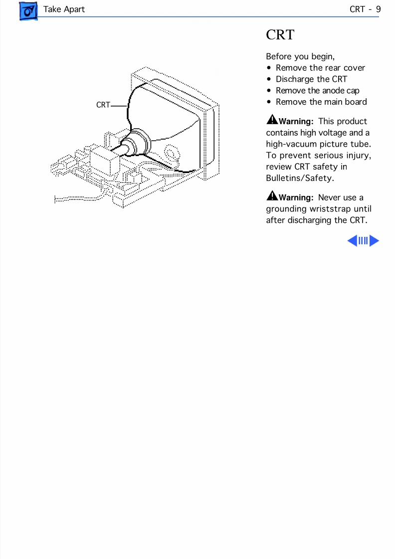
CRT
Before you begin,
• Remove the rear cover
• Discharge the CRT
• Remove the anode cap• Remove the main board
±Warning: This product
contains high voltage and a
high-vacuum picture tube.
To prevent serious injury,
review CRT safety in
Bulletins/Safety.
±Warning: Never use a
grounding wriststrap until
after discharging the CRT.
CRT
8/16/2019 12- Monochrome Display
http://slidepdf.com/reader/full/12-monochrome-display 26/58
Take Apart CRT - 10
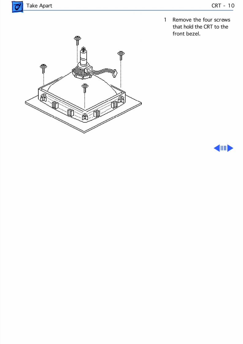
1 Remove the four screws
that hold the CRT to the
front bezel.
8/16/2019 12- Monochrome Display
http://slidepdf.com/reader/full/12-monochrome-display 27/58
Take Apart CRT - 11
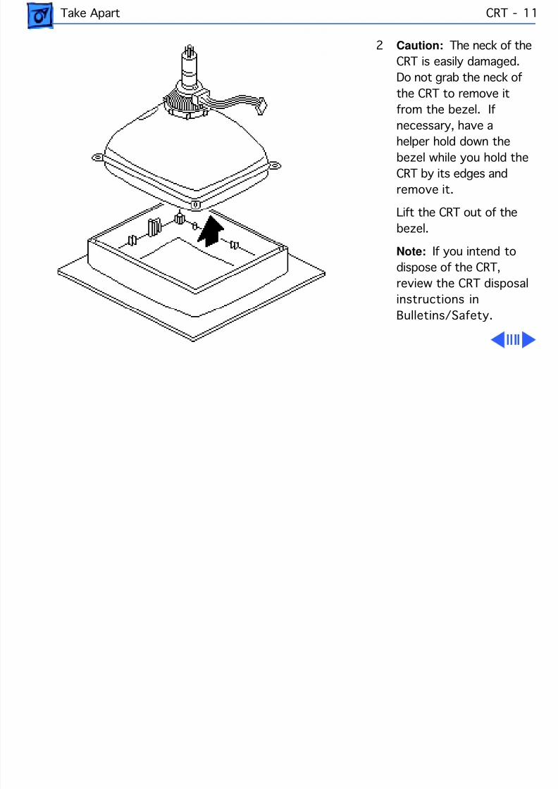
2 Caution: The neck of the
CRT is easily damaged.
Do not grab the neck of
the CRT to remove it
from the bezel. If
necessary, have ahelper hold down the
bezel while you hold the
CRT by its edges and
remove it.
Lift the CRT out of the
bezel.
Note: If you intend to
dispose of the CRT,
review the CRT disposal
instructions in
Bulletins/Safety.
8/16/2019 12- Monochrome Display
http://slidepdf.com/reader/full/12-monochrome-display 28/58
Take Apart CRT - 12
Replacement Note: If
you replace the CRT,
perform the video
adjustment procedure.
See “Video” in
Adjustments.
8/16/2019 12- Monochrome Display
http://slidepdf.com/reader/full/12-monochrome-display 29/58
Take Apart Contrast/Brightness Assembly - 13
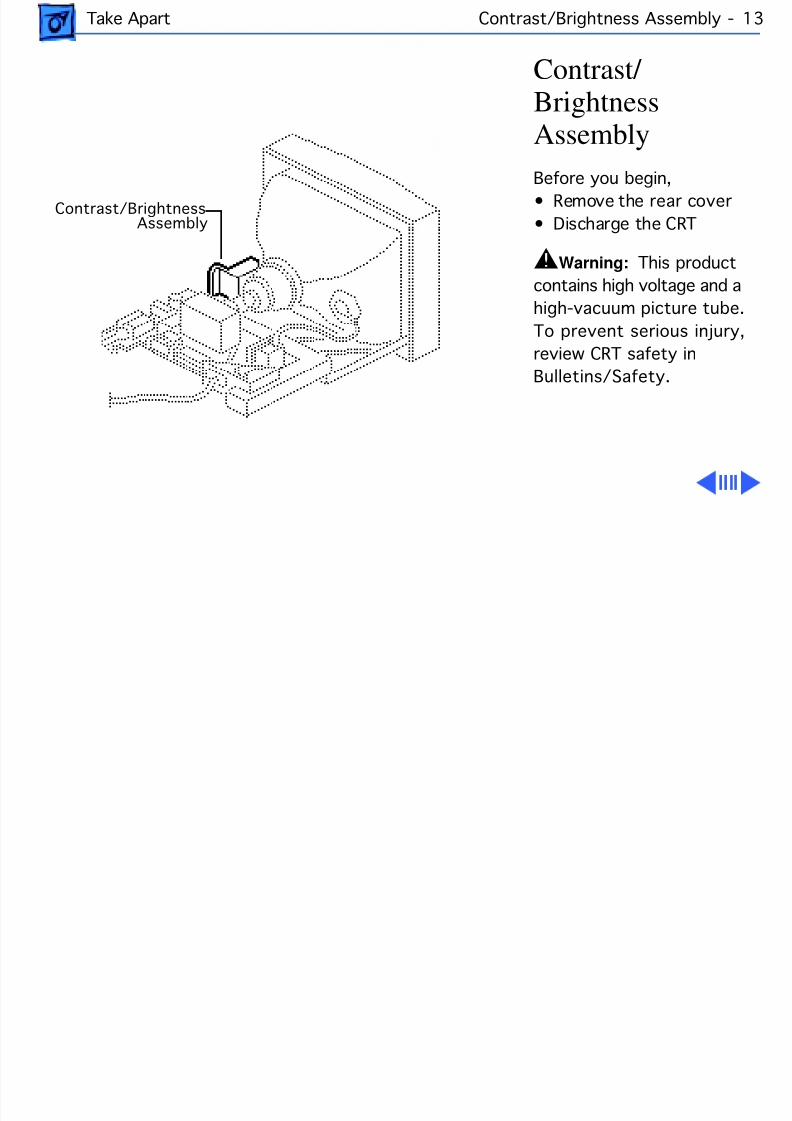
Contrast/ BrightnessAssembly
Before you begin,• Remove the rear cover
• Discharge the CRT
±Warning: This product
contains high voltage and a
high-vacuum picture tube.
To prevent serious injury,
review CRT safety in
Bulletins/Safety.
Contrast/Brightness Assembly
8/16/2019 12- Monochrome Display
http://slidepdf.com/reader/full/12-monochrome-display 30/58
Take Apart Contrast/Brightness Assembly - 14
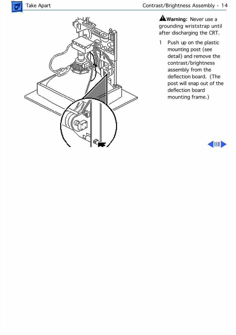
±Warning: Never use a
grounding wriststrap until
after discharging the CRT.
1 Push up on the plastic
mounting post (see
detail) and remove thecontrast/brightness
assembly from the
deflection board. (The
post will snap out of the
deflection board
mounting frame.)
8/16/2019 12- Monochrome Display
http://slidepdf.com/reader/full/12-monochrome-display 31/58
Take Apart Contrast/Brightness Assembly - 15
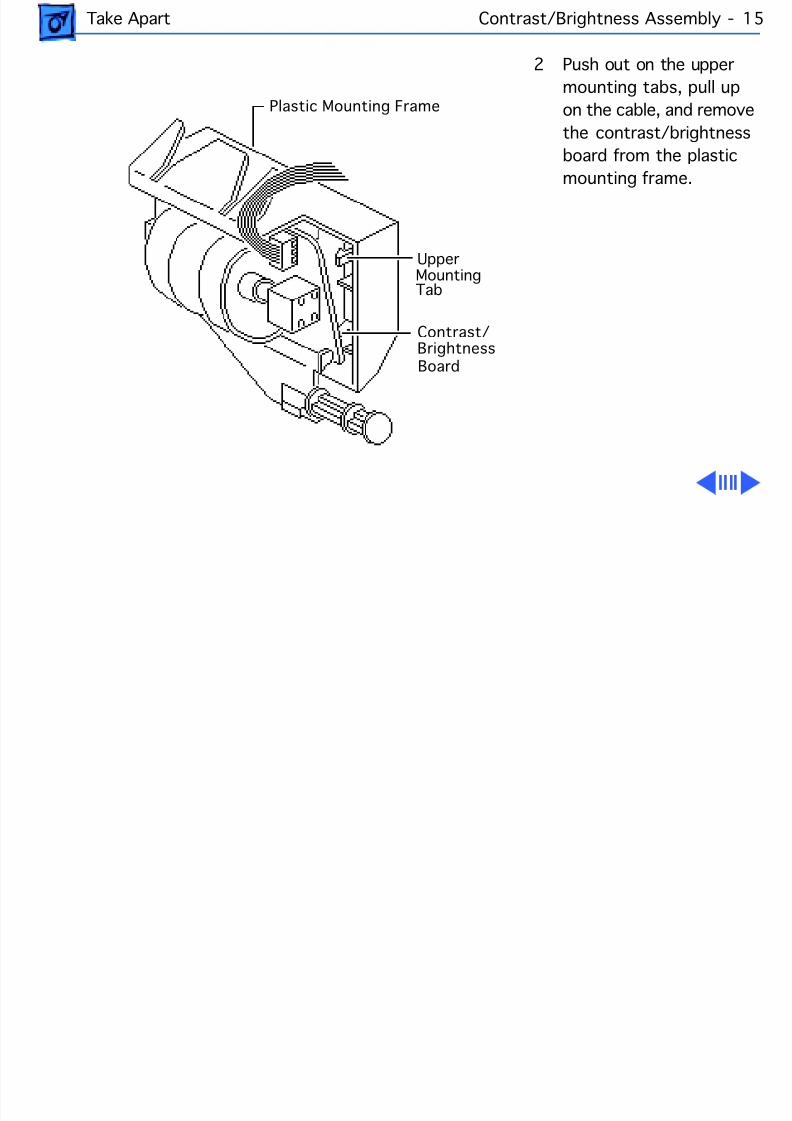
2 Push out on the upper
mounting tabs, pull up
on the cable, and remove
the contrast/brightness
board from the plastic
mounting frame.
Plastic Mounting Frame
UpperMountingTab
Contrast/Brightness
Board
8/16/2019 12- Monochrome Display
http://slidepdf.com/reader/full/12-monochrome-display 32/58
Take Apart Contrast/Brightness Assembly - 16
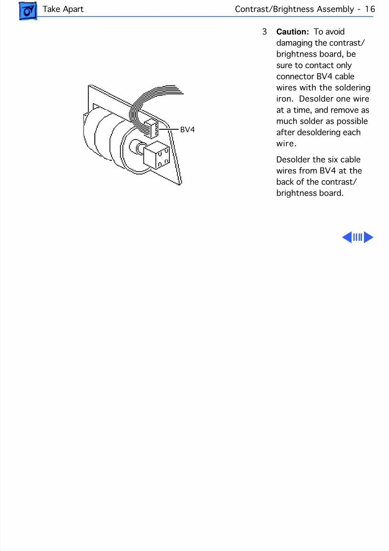
3 Caution: To avoid
damaging the contrast/
brightness board, be
sure to contact only
connector BV4 cable
wires with the solderingiron. Desolder one wire
at a time, and remove as
much solder as possible
after desoldering each
wire.
Desolder the six cable
wires from BV4 at the
back of the contrast/brightness board.
BV4
8/16/2019 12- Monochrome Display
http://slidepdf.com/reader/full/12-monochrome-display 33/58
Take Apart Contrast/Brightness Assembly - 17
4 Pull the six cable wires
loose from the board.
Using a desoldering tool,
remove all remaining
solder from the holes in
the board.
8/16/2019 12- Monochrome Display
http://slidepdf.com/reader/full/12-monochrome-display 34/58
Take Apart LED - 18
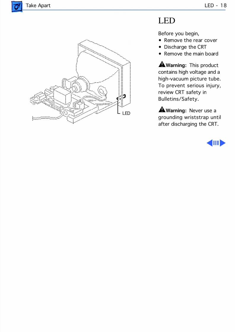
LED
Before you begin,
• Remove the rear cover
• Discharge the CRT
• Remove the main board
±Warning: This product
contains high voltage and a
high-vacuum picture tube.
To prevent serious injury,
review CRT safety in
Bulletins/Safety.
±Warning: Never use agrounding wriststrap until
after discharging the CRT.
LED
8/16/2019 12- Monochrome Display
http://slidepdf.com/reader/full/12-monochrome-display 35/58
Take Apart LED - 19
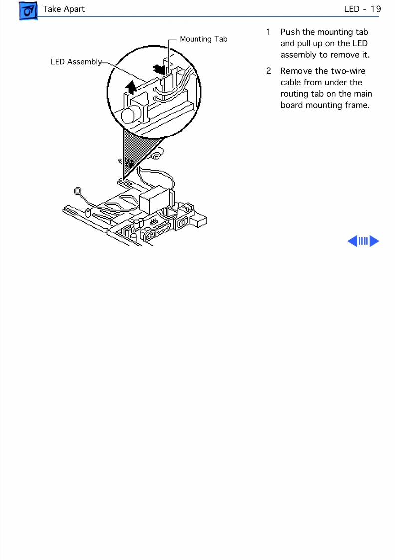
1 Push the mounting tab
and pull up on the LED
assembly to remove it.
2 Remove the two-wire
cable from under the
routing tab on the mainboard mounting frame.
Mounting Tab
LED Assembly
8/16/2019 12- Monochrome Display
http://slidepdf.com/reader/full/12-monochrome-display 36/58
Take Apart LED - 20
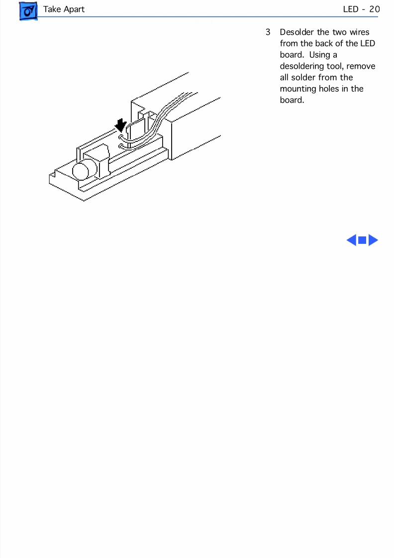
3 Desolder the two wires
from the back of the LED
board. Using a
desoldering tool, remove
all solder from the
mounting holes in theboard.
8/16/2019 12- Monochrome Display
http://slidepdf.com/reader/full/12-monochrome-display 37/58
Service SourceK
Adjustments
Macintosh 12 MonochromeDisplay
8/16/2019 12- Monochrome Display
http://slidepdf.com/reader/full/12-monochrome-display 38/58
Adjustments Geometry - 1
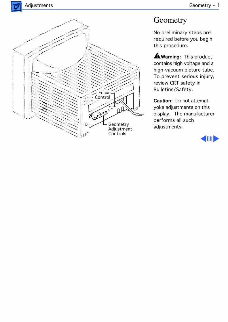
Geometry
No preliminary steps are
required before you begin
this procedure.
±Warning: This product
contains high voltage and a
high-vacuum picture tube.
To prevent serious injury,
review CRT safety in
Bulletins/Safety.
Caution: Do not attempt
yoke adjustments on thisdisplay. The manufacturer
performs all such
adjustments.
Focus
Geometry AdjustmentControls
Control
8/16/2019 12- Monochrome Display
http://slidepdf.com/reader/full/12-monochrome-display 39/58
Adjustments Geometry - 2
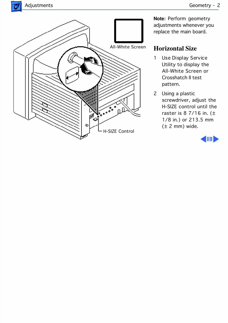
Note: Perform geometry
adjustments whenever you
replace the main board.
Horizontal Size
1 Use Display Service
Utility to display the
All-White Screen or
Crosshatch II test
pattern.
2 Using a plastic
screwdriver, adjust the
H-SIZE control until theraster is 8 7/16 in. (±
1/8 in.) or 213.5 mm
(± 2 mm) wide.
All-White Screen
H-SIZE Control
8/16/2019 12- Monochrome Display
http://slidepdf.com/reader/full/12-monochrome-display 40/58
Adjustments Geometry - 3
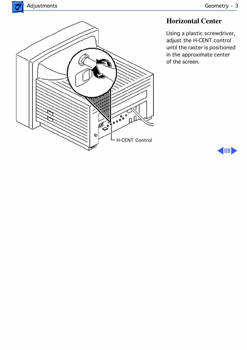
Horizontal Center
Using a plastic screwdriver,
adjust the H-CENT control
until the raster is positioned
in the approximate center
of the screen.
H-CENT Control
8/16/2019 12- Monochrome Display
http://slidepdf.com/reader/full/12-monochrome-display 41/58
Adjustments Geometry - 4
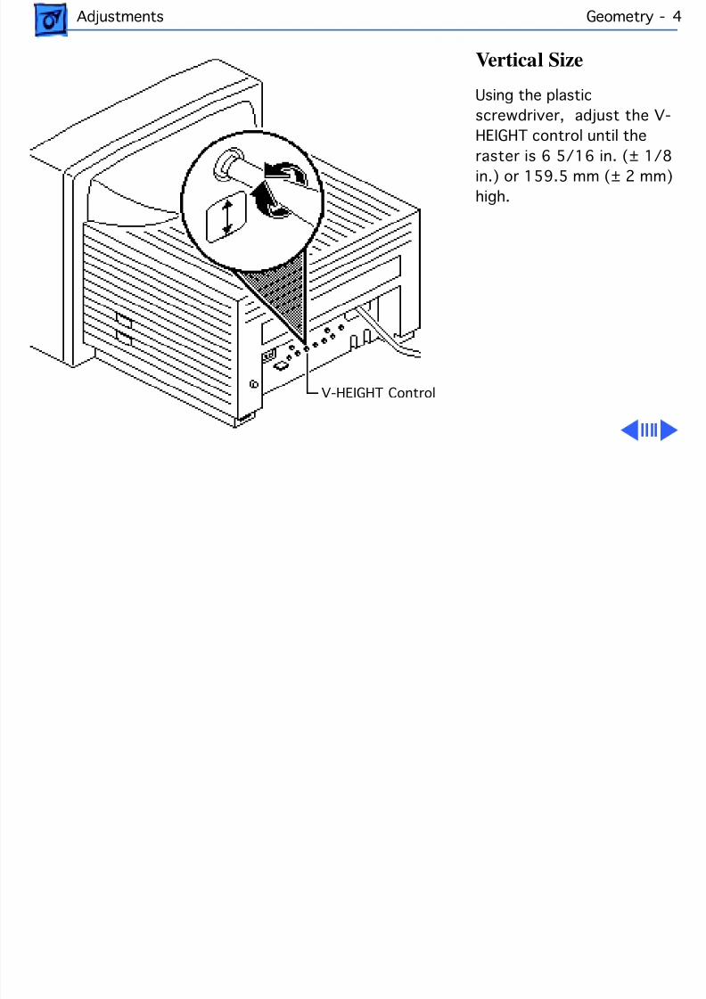
Vertical Size
Using the plastic
screwdriver, adjust the V-
HEIGHT control until the
raster is 6 5/16 in. (± 1/8
in.) or 159.5 mm (± 2 mm)
high.
V-HEIGHT Control

8/16/2019 12- Monochrome Display
http://slidepdf.com/reader/full/12-monochrome-display 42/58
Adjustments Geometry - 5
Vertical Center
1 Using the plastic
screwdriver, adjust the
V-CENT control until the
raster is positioned in
the approximate centerof the screen.
2 Verify that the raster
height is 6 5/16 in. (±
1/8 in.) or 159.5 mm
(± 2 mm) high. If not,
repeat the vertical size
and vertical center
adjustments.
V-CENTControl
8/16/2019 12- Monochrome Display
http://slidepdf.com/reader/full/12-monochrome-display 43/58
Adjustments Geometry - 6
Note: Vertical height
and horizontal size affect
each other. Recheck the
horizontal and vertical
specifications and, if
necessary, repeat theadjustments.
8/16/2019 12- Monochrome Display
http://slidepdf.com/reader/full/12-monochrome-display 44/58
Adjustments Geometry - 7
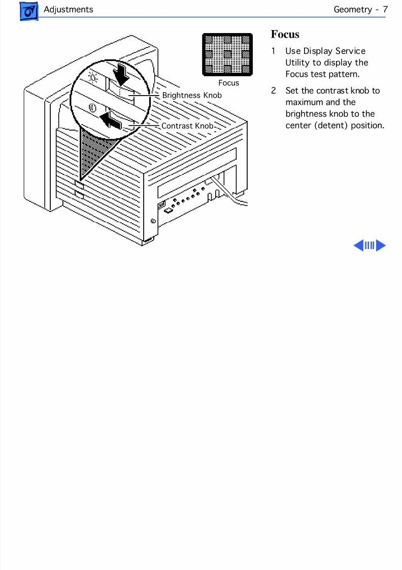
Focus
1 Use Display Service
Utility to display the
Focus test pattern.
2 Set the contrast knob tomaximum and the
brightness knob to the
center (detent) position.
Focus
Brightness Knob
Contrast Knob
8/16/2019 12- Monochrome Display
http://slidepdf.com/reader/full/12-monochrome-display 45/58
Adjustments Geometry - 8
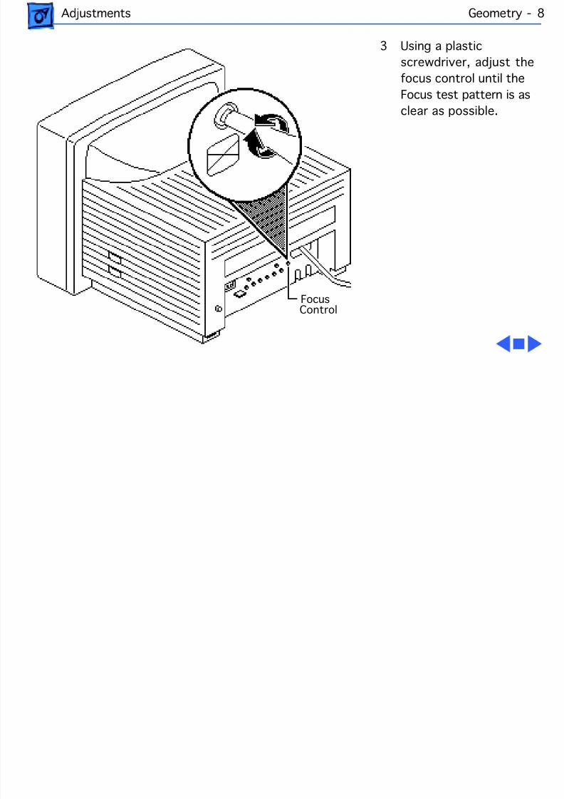
3 Using a plastic
screwdriver, adjust the
focus control until the
Focus test pattern is as
clear as possible.
FocusControl
8/16/2019 12- Monochrome Display
http://slidepdf.com/reader/full/12-monochrome-display 46/58
Adjustments Video - 9
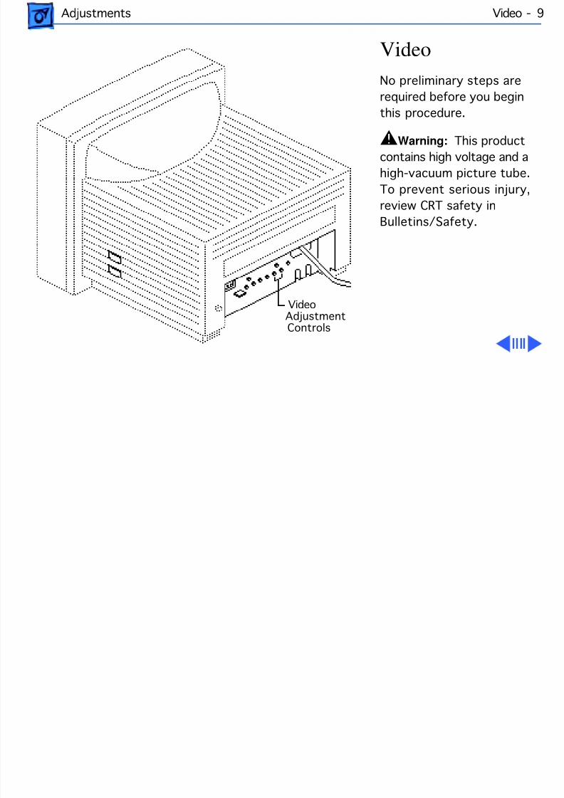
Video
No preliminary steps are
required before you begin
this procedure.
±Warning: This product
contains high voltage and a
high-vacuum picture tube.
To prevent serious injury,
review CRT safety in
Bulletins/Safety.
Video Adjustment Controls
8/16/2019 12- Monochrome Display
http://slidepdf.com/reader/full/12-monochrome-display 47/58
Adjustments Video - 10
±Warning: Because
adjustments are made from
the rear of the computer,
position a mirror to view
the computer screen. Do not
reach around the computerto adjust the controls.
Note: Perform video
adjustments whenever you
replace the CRT or video
board. You may need to
perform video adjustments
when you replace other
modules.
8/16/2019 12- Monochrome Display
http://slidepdf.com/reader/full/12-monochrome-display 48/58
Adjustments Video - 11
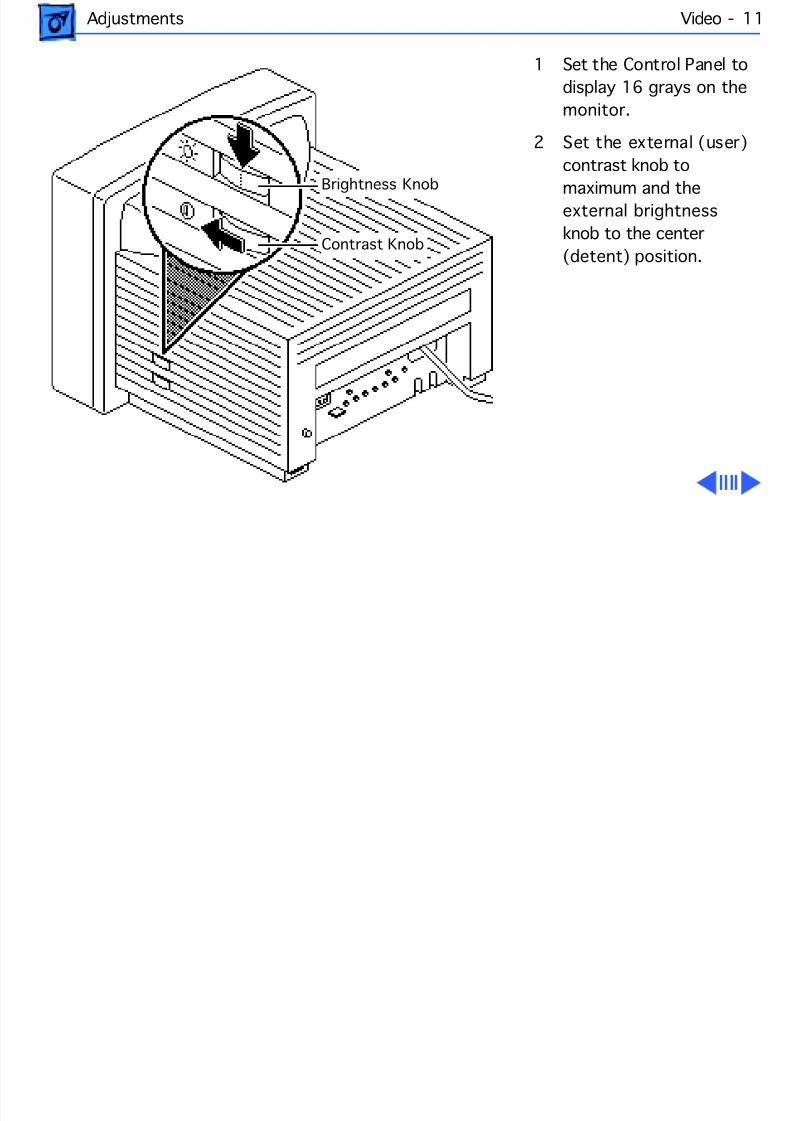
1 Set the Control Panel to
display 16 grays on the
monitor.
2 Set the external (user)
contrast knob to
maximum and theexternal brightness
knob to the center
(detent) position.
Brightness Knob
Contrast Knob
8/16/2019 12- Monochrome Display
http://slidepdf.com/reader/full/12-monochrome-display 49/58
Adjustments Video - 12
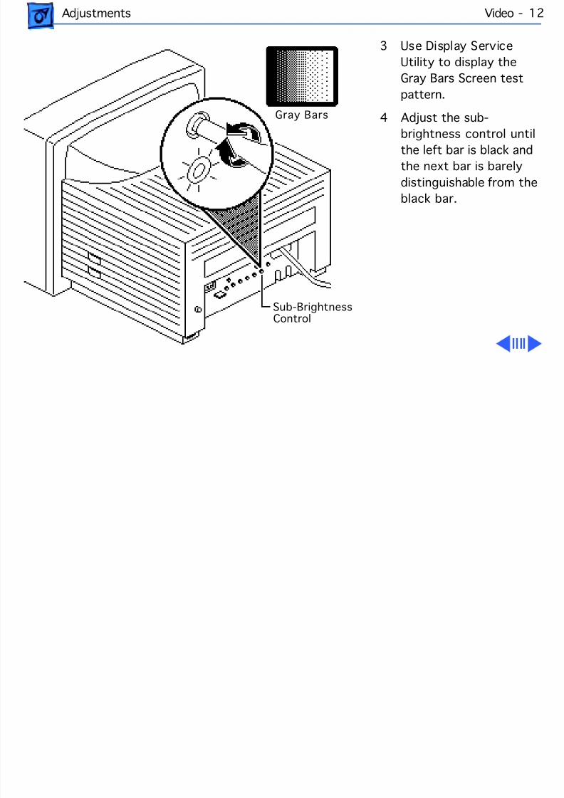
3 Use Display Service
Utility to display the
Gray Bars Screen test
pattern.
4 Adjust the sub-
brightness control untilthe left bar is black and
the next bar is barely
distinguishable from the
black bar.
Gray Bars
Sub-Brightness Control
8/16/2019 12- Monochrome Display
http://slidepdf.com/reader/full/12-monochrome-display 50/58
Adjustments Video - 13
Note: If you adjust the
sub-brightness control
too high, the edges of the
bars will appear dashed
or irregular. To correct
this problem, adjust thesub-brightness control
down about a quarter-
turn and then perform
the sub-brightness
adjustment.
8/16/2019 12- Monochrome Display
http://slidepdf.com/reader/full/12-monochrome-display 51/58
Adjustments Video - 14
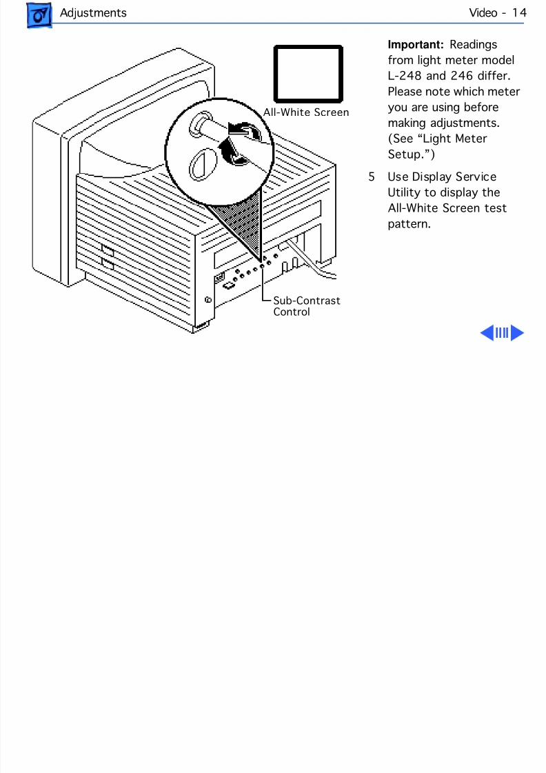
Important: Readings
from light meter model
L-248 and 246 differ.
Please note which meter
you are using before
making adjustments.(See “Light Meter
Setup.”)
5 Use Display Service
Utility to display the
All-White Screen test
pattern.
All-White Screen
Sub-Contrast Control
8/16/2019 12- Monochrome Display
http://slidepdf.com/reader/full/12-monochrome-display 52/58
Adjustments Video - 15
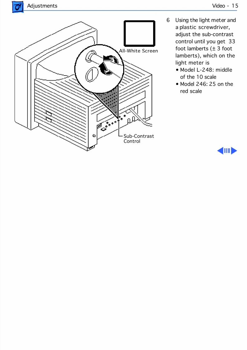
6 Using the light meter and
a plastic screwdriver,
adjust the sub-contrast
control until you get 33
foot lamberts (± 3 foot
lamberts), which on thelight meter is
• Model L-248: middle
of the 10 scale
• Model 246: 25 on the
red scale
All-White Screen
Sub-Contrast Control
8/16/2019 12- Monochrome Display
http://slidepdf.com/reader/full/12-monochrome-display 53/58
Adjustments Video - 16
Important: Over time,
light meter tolerances
can vary. If you doubt
your meter’s accuracy,
verify the readings with
a known-good lightmeter or photometer.
8/16/2019 12- Monochrome Display
http://slidepdf.com/reader/full/12-monochrome-display 54/58
Adjustments Light Meter Setup - 17
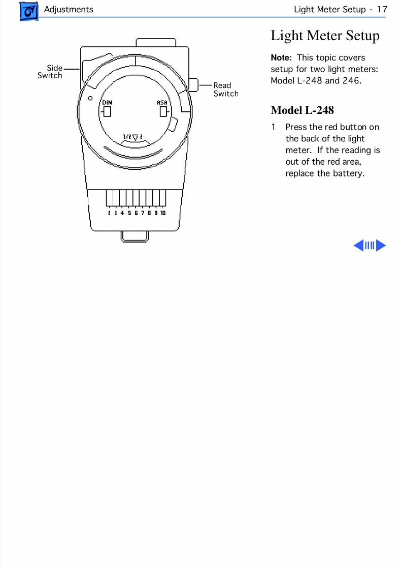
Light Meter Setup
Note: This topic covers
setup for two light meters:
Model L-248 and 246.
Model L-248
1 Press the red button on
the back of the light
meter. If the reading is
out of the red area,
replace the battery.
Read
Side Switch
Switch
8/16/2019 12- Monochrome Display
http://slidepdf.com/reader/full/12-monochrome-display 55/58
Adjustments Light Meter Setup - 18
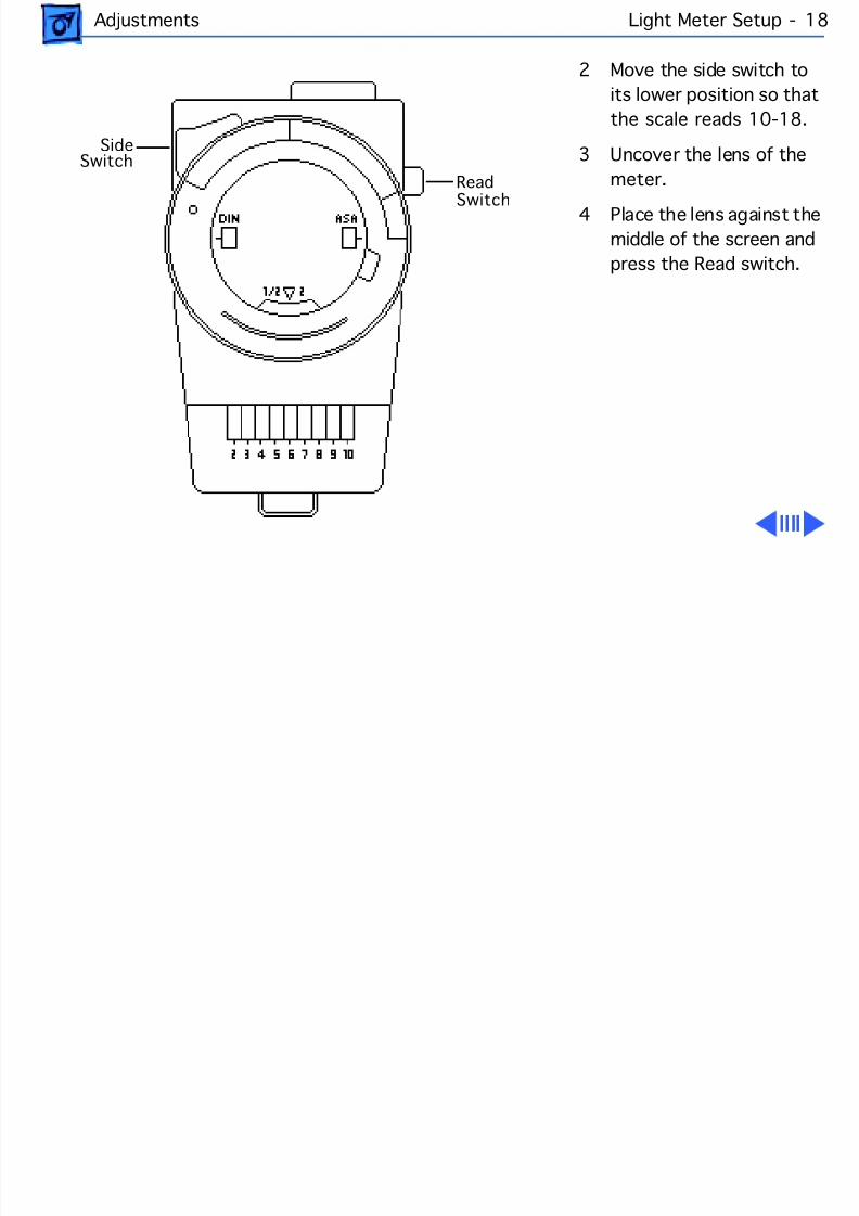
2 Move the side switch to
its lower position so that
the scale reads 10-18.
3 Uncover the lens of the
meter.
4 Place the lens against the
middle of the screen and
press the Read switch.
Read
Side Switch
Switch
8/16/2019 12- Monochrome Display
http://slidepdf.com/reader/full/12-monochrome-display 56/58
Adjustments Light Meter Setup - 19
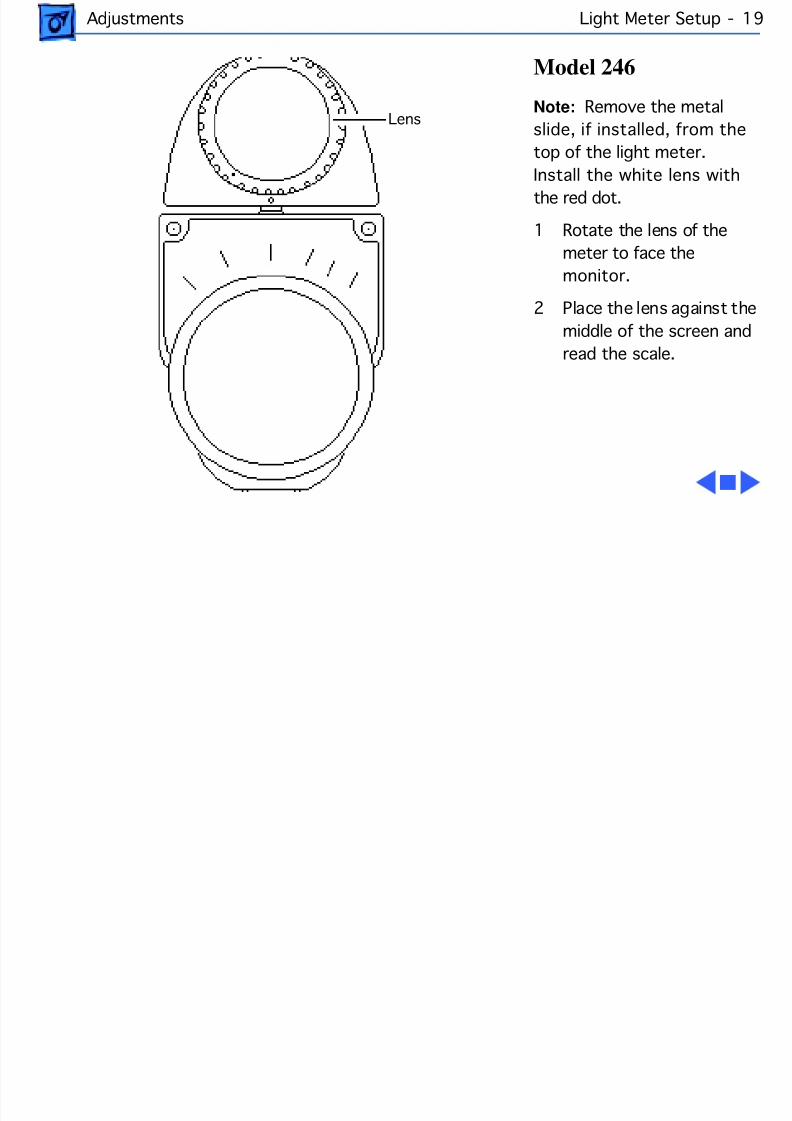
Model 246
Note: Remove the metal
slide, if installed, from the
top of the light meter.
Install the white lens with
the red dot.
1 Rotate the lens of the
meter to face the
monitor.
2 Place the lens against the
middle of the screen and
read the scale.
Lens
8/16/2019 12- Monochrome Display
http://slidepdf.com/reader/full/12-monochrome-display 57/58
Service SourceK
Exploded View
Macintosh 12 MonochromeDisplay
8/16/2019 12- Monochrome Display
http://slidepdf.com/reader/full/12-monochrome-display 58/58
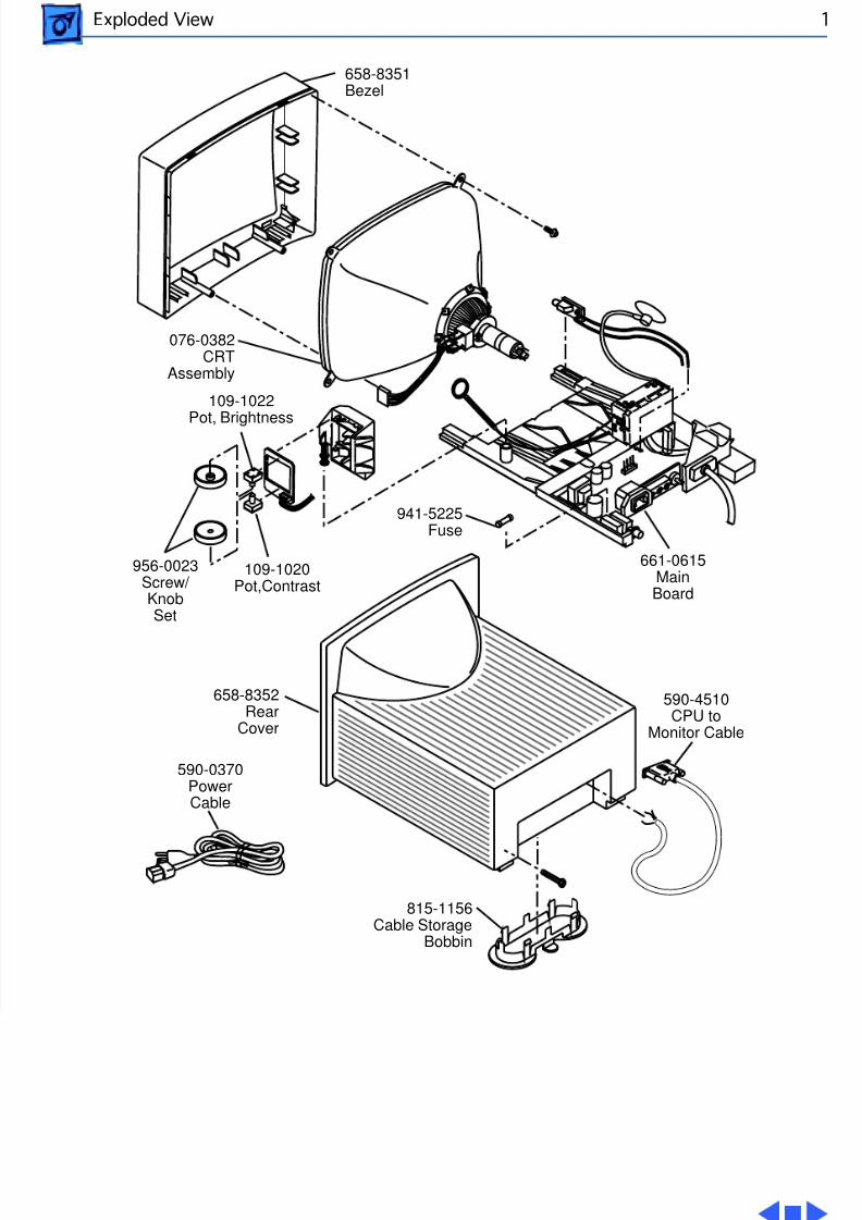
Exploded View 1
658-8351Bezel
590-0370PowerCable
658-8352Rear
Cover
076-0382CRT
Assembly
590-4510CPU to
Monitor Cable
815-1156Cable Storage
Bobbin
661-0615MainBoard
941-5225Fuse
109-1022Pot, Brightness
956-0023Screw/KnobSet
109-1020Pot,Contrast


![Macintosh 12'' Monochrome Display - 12_monochrome_display[1]](https://static.fdocuments.net/doc/165x107/577cc74b1a28aba711a09159/macintosh-12-monochrome-display-12monochromedisplay1.jpg)