12 Lead ECG Fundamentals: The Starting Place for … Lead ECG Fundamentals: The Starting Place for...
73
NTI 2009 Preconference Cynthia Webner, BSN, RN, CCRN-CMC www.cardionursing.com Presented By: Cynthia Webner, BSN, RN, CCRN-CMC Karen Marzlin, BSN, RN,CCRN-CMC www.cardionursing.com 1 12 Lead ECG Skills: Building Confidence for Clinical Practice NTI 2009 Preconference Session 803 2 12 Lead ECG Fundamentals: The Starting Place for The Starting Place for The Starting Place for The Starting Place for Linking Knowledge to Practice Linking Knowledge to Practice Linking Knowledge to Practice Linking Knowledge to Practice
Transcript of 12 Lead ECG Fundamentals: The Starting Place for … Lead ECG Fundamentals: The Starting Place for...

NTI 2009 Preconference
Cynthia Webner, BSN, RN, CCRN-CMC
www.cardionursing.com
Presented By:
Cynthia Webner, BSN, RN, CCRN-CMC
Karen Marzlin, BSN, RN,CCRN-CMC
www.cardionursing.com
1
12 Lead ECG Skills: Building Confidence for Clinical Practice
NTI 2009 Preconference
Session 803
2
12 Lead ECG Fundamentals: The Starting Place for The Starting Place for The Starting Place for The Starting Place for
Linking Knowledge to PracticeLinking Knowledge to PracticeLinking Knowledge to PracticeLinking Knowledge to Practice

NTI 2009 Preconference
Cynthia Webner, BSN, RN, CCRN-CMC
www.cardionursing.com
The journey of a thousand miles begins with one step.
- Lao Tsu
4
Framework for the Day
• Understand – don’t memorize
• Physiological basis
• Building blocks
• Start slow – fly wheel effect

NTI 2009 Preconference
Cynthia Webner, BSN, RN, CCRN-CMC
www.cardionursing.com
5
Electrical Conduction Electrical Conduction Electrical Conduction Electrical Conduction
PathwayPathwayPathwayPathway• SA Node
• Right and left Atrial Conduction
• AV Node
• Bundle of His
• Right and Left Bundle Branches
• Fascicles
• Purkinge Fibers
6
Normal 12 Lead ECGNormal 12 Lead ECGNormal 12 Lead ECGNormal 12 Lead ECGSTANDARD
LIMB LEADS
AUGMENTED
LIMB LEADS CHEST OR PRECORDIAL LEADS
2 Chest Electrodes One Chest Electrode

NTI 2009 Preconference
Cynthia Webner, BSN, RN, CCRN-CMC
www.cardionursing.com
7
Lead 1 aVR V1 V4
Lead 2 aVL V2 V5
Lead 3 aVF V3 V6
Two Sets of Leads Two Sets of Leads Two Sets of Leads Two Sets of Leads
• Limb LeadsLimb LeadsLimb LeadsLimb Leads
– Standard Limb
Leads
(I, II, and III)
– Augmented Limb
Leads
(aVR, aVL, aVF)
• Chest Leads Chest Leads Chest Leads Chest Leads
–Also called precordial leads
–V1 – V6

NTI 2009 Preconference
Cynthia Webner, BSN, RN, CCRN-CMC
www.cardionursing.com
9
Leads
Two Electrodes on Patient
• One positive electrode
• One negative electrode
• Records difference in electrical potential between selected electrodes
• Leads I, II, and III
One Electrode on Patient
• One positive electrode
• One reference point
– Zero electrical potential
– Center of heart
• Leads aVR, aVL, aVF
• V1- V6
+ -
Importance of the Positive Electrode
Reason 1
• Consider the positive electrode the “eye” or “the camera”
+RA
RV
LA
LV

NTI 2009 Preconference
Cynthia Webner, BSN, RN, CCRN-CMC
www.cardionursing.com
11
The Camera Looks at Different Parts of
the Myocardium
12
Electrode Placement
Limb Leads

NTI 2009 Preconference
Cynthia Webner, BSN, RN, CCRN-CMC
www.cardionursing.com
The Ground
• Note: Nothing travels toward the right leg as a positive electrode.
• The right leg is the ground used to absorb any excess electrical activity.
14
Standard Limb LeadsStandard Limb LeadsStandard Limb LeadsStandard Limb Leads
LeadsLeadsLeadsLeads I, II, IIII, II, IIII, II, IIII, II, III

NTI 2009 Preconference
Cynthia Webner, BSN, RN, CCRN-CMC
www.cardionursing.com
15
Standard Limb LeadsLead I
- + LEAD I
HIGH
LATERAL
WALL
16
Standard Limb Leads
Lead II
-
+
LEAD IIINFERIOR
WALL

NTI 2009 Preconference
Cynthia Webner, BSN, RN, CCRN-CMC
www.cardionursing.com
17
Standard Limb Leads
Lead III
-
+
LEAD III
INFERIOR WALL
18
Standard Limb Lead
Leads I, II, III
+/-
+
LEAD III
-LEAD I
LEAD II

NTI 2009 Preconference
Cynthia Webner, BSN, RN, CCRN-CMC
www.cardionursing.com
19
Augmented Limb LeadsAugmented Limb LeadsAugmented Limb LeadsAugmented Limb Leads
LeadsLeadsLeadsLeads aVR, aVL, aVFaVR, aVL, aVFaVR, aVL, aVFaVR, aVL, aVF
UNIPOLAR
20
Augmented Limb LeadsaVR
+
aVR
View of NOTHING related to
LV

NTI 2009 Preconference
Cynthia Webner, BSN, RN, CCRN-CMC
www.cardionursing.com
21
Augmented Limb LeadsaVL
+
aVL
High Lateral Wall
22
Augmented Limb LeadsaVF
+aVF
Inferior Wall

NTI 2009 Preconference
Cynthia Webner, BSN, RN, CCRN-CMC
www.cardionursing.com
23
Augmented Limb Leads
Lead Placement: Leads aVR, aVL, aVF
+
+
+aVR aVL
aVF
24
Einthoven’s Triangle
Label Leads I, II, III Then add aVR, aVL, aVF

NTI 2009 Preconference
Cynthia Webner, BSN, RN, CCRN-CMC
www.cardionursing.com
25
� AVR � AVL
AVF�
26
Chest (Precordial) Leads

NTI 2009 Preconference
Cynthia Webner, BSN, RN, CCRN-CMC
www.cardionursing.com
27
Electrode PlacementChest (Precordial) Leads
• Lead V1
– 4th ICS, RSB
• Lead V2
– 4th ICS, LSB
• Lead V3
– Midway Between V2 & V4
• Lead V4
– L midclavicular line, 5th ICS
• Lead V5
– L anterior axillary line, same level as V4
• Lead V6
– L midaxillary line, same level as V4
Used with permission from: Aehlert. B (2002). ECG’s made
easy (2nd ed.). St. Louis, MO: Mosby, Inc. Pg. 197.
28
Frontal vs. Horizontal Planes

NTI 2009 Preconference
Cynthia Webner, BSN, RN, CCRN-CMC
www.cardionursing.com
29
A Closer Look at Chest Leads
The Point of View of the Positive Electrode
• V1 – Septum (RV)
• V2 – Septum
30
A Closer Look at Chest Leads
The Point of View of the Positive Electrode
• V3 – Anterior
• V4 – Anterior

NTI 2009 Preconference
Cynthia Webner, BSN, RN, CCRN-CMC
www.cardionursing.com
31
A Closer Look at Chest Leads
The Point of View of the Positive Electrode
V5 – Low Lateral V6 – Low Lateral
32
Lead 1Left Arm
High Lateral Wall
aVRRight Arm
V14th ICS, RSB
Septal Wall
V4L MCL, 5th ICS
Anterior Wall
Lead 2Left Leg
Inferior Wall
aVLLeft Arm
High Lateral Wall
V24th ICS, LSB
Septal Wall
V5L anterior
axillary, same
level as V4
Low Lateral Wall
Lead 3Left Leg
Inferior Wall
aVFLeft Leg
Inferior Wall
V3Midway Between
V2 & V4
Anterior Wall
V6L midaxillary
line, same level
as V4
Low Lateral Wall

NTI 2009 Preconference
Cynthia Webner, BSN, RN, CCRN-CMC
www.cardionursing.com
33
Identifying Normal Complexes
ECG Paper – Horizontal AxisNormal speed 25 mm/
sec
• Smallest box 1mm x 1mm
• 1 small box 0.04 sec
• 1 large box 0.20 sec
• 5 large boxes 1.0 sec

NTI 2009 Preconference
Cynthia Webner, BSN, RN, CCRN-CMC
www.cardionursing.com
ECG Paper – Vertical Axis
• Voltage or amplitude
• Measured in millivolts(mV) or millimeters (mm)
• EKG machine calibrated so that 1 mV produces a deflection measuring exactly 10 mm tall
• 1 small box = 1 mm high
• 1 large box = 5 mm high
Measuring Rate on Irregular Rhythms
• Irregular rhythms
– Count number of R-R intervals in a 6 second strip and multiply by 10
1 2 3 4 5 6
6 X 10 = 60
36

NTI 2009 Preconference
Cynthia Webner, BSN, RN, CCRN-CMC
www.cardionursing.com
1 2 3 4
Measuring Rate on Regular Rhythms
• Regular rhythms
– Count number of large boxes between R waves and divide into 300:
1 = 300 6 = 50
2 = 150 7 = 43
3 = 100 8 = 37
4 = 75 9 = 33
5 = 60 10 = 30
300 ÷÷÷÷ 4 = 7537
Calculating Rate

NTI 2009 Preconference
Cynthia Webner, BSN, RN, CCRN-CMC
www.cardionursing.com
Rate Ruler
1 2 3 4
4 big boxes + 2 tiny boxes
4 big + 2 tiny = rate 68
39
ECG Waves and Intervals
40

NTI 2009 Preconference
Cynthia Webner, BSN, RN, CCRN-CMC
www.cardionursing.com
41
P Waves
• P waves represent atrial depolarization and spread of electrical impulse through the atria
• First half of P represents depolarization from the SA node though the RA to the AV node
• Down slope of P wave represents stimulation of the LA
42
Normal P Wave Criteria
• Smooth and
rounded
• No more than 2.5
mm in height
• No more than .11
seconds in duration

NTI 2009 Preconference
Cynthia Webner, BSN, RN, CCRN-CMC
www.cardionursing.com
43
QRS Complex• Not every QRS complex contains a Q
wave, R wave and S wave!!
• Q – always negative (below baseline)
• R – first positive above the baseline
• R’ – second positive above the baseline
• S – negative deflection following R wave or second component to entirely –complex
• S’ – second negative deflection
44
QS qR QR Qr qRs
R RS rS rSR’ Rs
LetLetLetLet’’’’s Practices Practices Practices Practice

NTI 2009 Preconference
Cynthia Webner, BSN, RN, CCRN-CMC
www.cardionursing.com
ST Segment
• In limb leads the ST segment is normally isoelectric but may be slightly elevated or depressed by less than 1mm
• In precordial leads ST segment is elevation is normally not more than 1 to 2 mm
ST SegmentThe “J Point”
• “Junction” where
the QRS complex
and the ST
segment meet.
NTI 2009 Preconference
Cynthia Webner, BSN, RN, CCRN-CMC
www.cardionursing.com
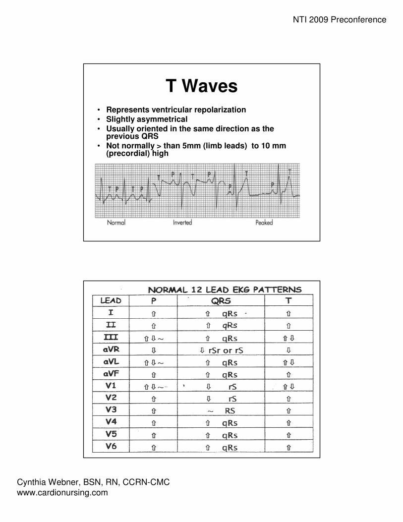
T Waves• Represents ventricular repolarization• Slightly asymmetrical• Usually oriented in the same direction as the
previous QRS• Not normally > than 5mm (limb leads) to 10 mm
(precordial) high
48

NTI 2009 Preconference
Cynthia Webner, BSN, RN, CCRN-CMC
www.cardionursing.com
49
The Importance of the Positive Electrode
Reason 2
• If a wave of depolarization moves TOWARDthe + electrode, the waveform on the ECG graph will be upright or +
50
The Importance of the Positive Electrode
Reason 2
• If a wave of depolarization moves TOWARD the – electrode, the waveform on the ECG graph will be downward or –

NTI 2009 Preconference
Cynthia Webner, BSN, RN, CCRN-CMC
www.cardionursing.com
51
The Importance of the Positive Electrode
Reason 2
A biphasic wave form occurs when the direction of depolarization is PERPENDICULAR to the +
electrode
Heart aVL
- +
52
A Closer Look at Lead I
• Lead 1 Normals– P waves: Upright and
gently rounded
– QRS Complex: Upright
– T Waves: Upright and
smaller than QRS

NTI 2009 Preconference
Cynthia Webner, BSN, RN, CCRN-CMC
www.cardionursing.com
53
A Closer Look at Lead II
• Lead II normals– P wave: upright and
gently rounded
– QRS: upright
– T wave: upright and smaller than QRS
54
A Closer Look at Lead III
• Lead III normals
– P wave: upright and
gently rounded
– QRS Complex: Upright
– T wave: Upright and
smaller than QRS

NTI 2009 Preconference
Cynthia Webner, BSN, RN, CCRN-CMC
www.cardionursing.com
55
A Closer Look at aVR
• aVR Normals– P wave: inverted
– QRS: inverted (rSr’ or
rS)
– T wave: inverted
56
A Closer Look at aVL
• aVL Normals– P waves: Upright or
inverted
– QRS: Upright or inverted
– T wave: Upright or inverted (but no down sloping of ST)

NTI 2009 Preconference
Cynthia Webner, BSN, RN, CCRN-CMC
www.cardionursing.com
57
A Closer Look at aVF
• aVF Normals– P waves: upright and
gently rounded
– QRS: Upright
– T wave: Upright and
smaller than QRS
58
A Closer Look at V1
• Normal V1
– P wave: inverted,
upright or biphasic
– QRS: inverted with rS
pattern
– T waves: inverted or
upright
NTI 2009 Preconference
Cynthia Webner, BSN, RN, CCRN-CMC
www.cardionursing.com
59
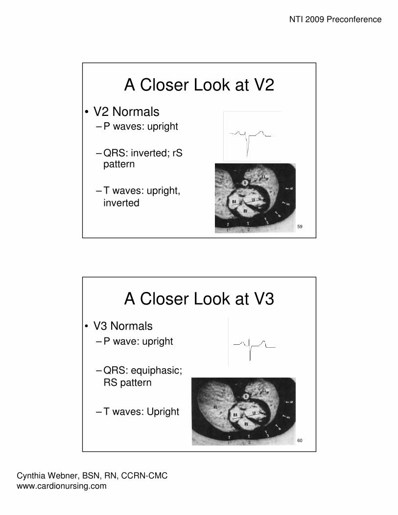
A Closer Look at V2
• V2 Normals– P waves: upright
– QRS: inverted; rSpattern
– T waves: upright,
inverted
60
A Closer Look at V3
• V3 Normals
– P wave: upright
– QRS: equiphasic;
RS pattern
– T waves: Upright
NTI 2009 Preconference
Cynthia Webner, BSN, RN, CCRN-CMC
www.cardionursing.com
61
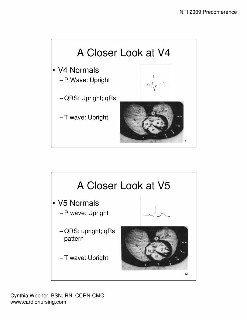
A Closer Look at V4
• V4 Normals– P Wave: Upright
– QRS: Upright; qRs
– T wave: Upright
62
A Closer Look at V5
• V5 Normals– P wave: Upright
– QRS: upright; qRs
pattern
– T wave: Upright

NTI 2009 Preconference
Cynthia Webner, BSN, RN, CCRN-CMC
www.cardionursing.com
63
A Closer Look at V6
• V6 Normals– P wave: upright
– QRS: upright; qRs
pattern
– T wave: upright
64
Normal V1-6: R Wave Progression
• The R wave becomes taller and the S wave becomes smaller as the electrode is moved from right to left
• This pattern is called R wave progression
NTI 2009 Preconference
Cynthia Webner, BSN, RN, CCRN-CMC
www.cardionursing.com
65
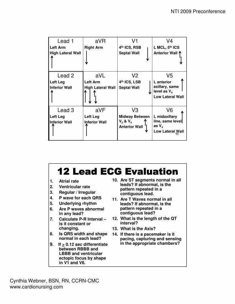
Lead 1Left Arm
High Lateral Wall
aVRRight Arm
V14th ICS, RSB
Septal Wall
V4L MCL, 5th ICS
Anterior Wall
Lead 2Left Leg
Inferior Wall
aVLLeft Arm
High Lateral Wall
V24th ICS, LSB
Septal Wall
V5L anterior
axillary, same
level as V4
Low Lateral Wall
Lead 3Left Leg
Inferior Wall
aVFLeft Leg
Inferior Wall
V3Midway Between
V2 & V4
Anterior Wall
V6L midaxillary
line, same level
as V4
Low Lateral Wall
12 Lead ECG Evaluation12 Lead ECG Evaluation12 Lead ECG Evaluation12 Lead ECG Evaluation1. Atrial rate
2. Ventricular rate
3. Regular / Irregular
4. P wave for each QRS
5. Underlying rhythm
6. Are P waves abnormal in any lead?
7. Calculate P-R Interval –is it constant or changing.
8. Is QRS width and shape normal in each lead?
9. If > 0.12 sec differentiate between RBBB and LBBB and ventricular ectopic focus by shape in V1 and V6.
10. Are ST segments normal in all leads? If abnormal, is the pattern repeated in a contiguous lead.
11. Are T Waves normal in all leads? If abnormal, is the pattern repeated in a contiguous lead?
12. What is the length of the QT interval?
13. What is the Axis?
14. If there is a pacemaker is it pacing, capturing and sensing in the appropriate chambers?

NTI 2009 Preconference
Cynthia Webner, BSN, RN, CCRN-CMC
www.cardionursing.com
67
68
NTI 2009 Preconference
Cynthia Webner, BSN, RN, CCRN-CMC
www.cardionursing.com
69
Utilizing the Bedside Monitor to
Provide 12 Lead ECG Information
70
Three Reasons for Bedside Cardiac Monitoring
Arrhythmia Detection
Ischemia Monitoring
QT Interval Monitoring

NTI 2009 Preconference
Cynthia Webner, BSN, RN, CCRN-CMC
www.cardionursing.com
71
Arrhythmia Monitoring
• Candidates • Primary purpose for all patients on cardiac monitor
• Purpose • Detection of and prompt intervention for life threatening
arrhythmias
• Leads of Choice • V1
• V6 (or MCL6)
72
Ischemia (ST) Monitoring
• Candidates
– Patients admitted with Acute Coronary Syndrome
– Patients post PCI
– Patients admitted to Chest Pain Center or Chest
Pain Center protocol
• Purpose
– To monitor changes in ST segments (compared to
baseline) in select leads
• Leads of Choice
– Based on area of known or potential ischemia
NTI 2009 Preconference
Cynthia Webner, BSN, RN, CCRN-CMC
www.cardionursing.com
73
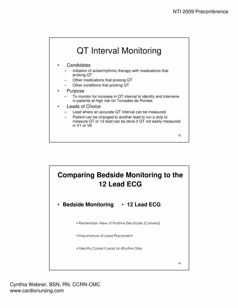
QT Interval Monitoring
• Candidates – Initiation of antiarrhythmic therapy with medications that
prolong QT
– Other medications that prolong QT
– Other conditions that prolong QT
• Purpose – To monitor for increase in QT interval to identify and intervene
in patients at high risk for Torsades de Pointes
• Leads of Choice – Lead where an accurate QT Interval can be measured
– Patient can be changed to another lead to run a strip to measure QT or 12 lead can be done if QT not easily measured in V1 or V6
74
Comparing Bedside Monitoring to the
12 Lead ECG
• Bedside Monitoring • 12 Lead ECG
�Remember View of Positive Electrode (Camera)
�Importance of Lead Placement
�Identify Correct Lead on Rhythm Strip

NTI 2009 Preconference
Cynthia Webner, BSN, RN, CCRN-CMC
www.cardionursing.com
75
Arrhythmia Monitoring
• When a patient has a wide complex tachycardia it is important to determine if the tachycardia is:
• Ventricular tachycardia
• Or… SVT (including atrial arrhythmias) with a co-existing bundle branch block
• Since both rhythms are wide and fast it is often difficult to differentiate
76
Why V1 and V6 (MCL6) for Arrhythmia
Monitoring
• V1 • Looks different for ventricular tachycardia and
bundle branch block
• Helps to determine if rhythm is ventricular
tachycardia (VT) or SVT with a bundle branch
block
• Position of V1 electrode
NTI 2009 Preconference
Cynthia Webner, BSN, RN, CCRN-CMC
www.cardionursing.com
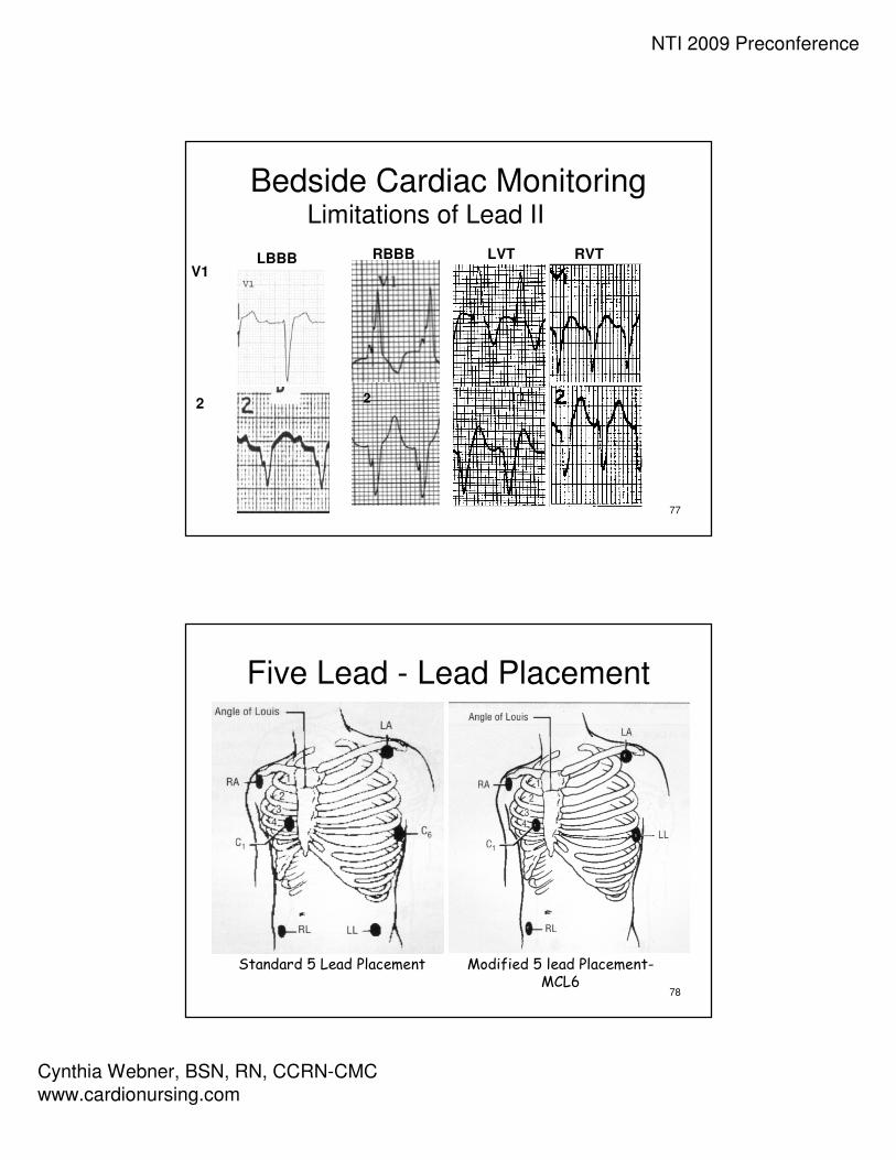
77
Bedside Cardiac MonitoringLimitations of Lead II
LBBB RBBB
2
V1
2
LVT RVT
78
Five Lead - Lead Placement
Standard 5 Lead Placement Modified 5 lead Placement-MCL6

NTI 2009 Preconference
Cynthia Webner, BSN, RN, CCRN-CMC
www.cardionursing.com
79
3 Lead Placement for MCL1
80
ECG Fundamentals
Calculating Cardiac Axis
NTI 2009 Preconference
Cynthia Webner, BSN, RN, CCRN-CMC
www.cardionursing.com
81
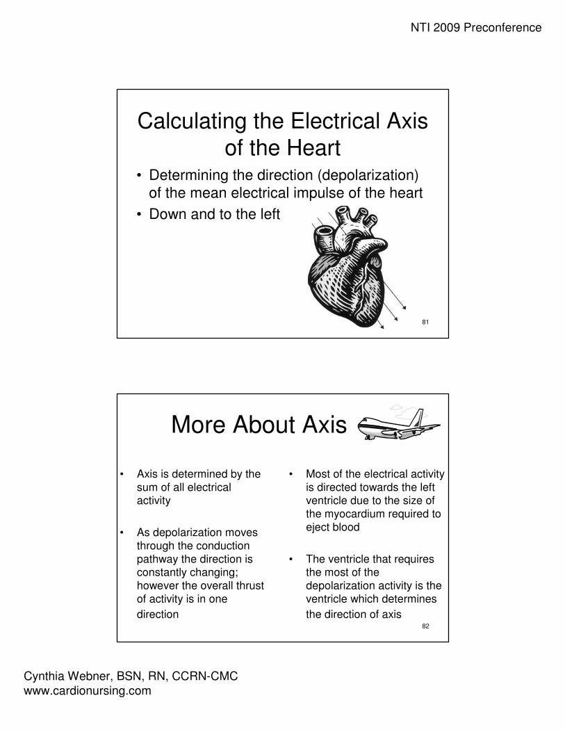
Calculating the Electrical Axis
of the Heart• Determining the direction (depolarization)
of the mean electrical impulse of the heart
• Down and to the left
82
More About Axis
• Axis is determined by the
sum of all electrical activity
• As depolarization moves
through the conduction
pathway the direction is constantly changing;
however the overall thrust
of activity is in one
direction
• Most of the electrical activity
is directed towards the left ventricle due to the size of
the myocardium required to
eject blood
• The ventricle that requires the most of the
depolarization activity is the
ventricle which determines
the direction of axis

NTI 2009 Preconference
Cynthia Webner, BSN, RN, CCRN-CMC
www.cardionursing.com
83
Axis Wheel
84
Bipolar Frontal Plane Leads
• Lead I– Left arm positive
– Right arm negative
• Lead II– Left leg positive
– Right arm negative
• Lead III– Left leg positive
– Left arm negative
I
II III

NTI 2009 Preconference
Cynthia Webner, BSN, RN, CCRN-CMC
www.cardionursing.com
85
Unipolar Frontal Plane Leads
Reference point in center of chest –“telephoto lens”
• aVR– Right arm positive
• aVL– Left arm positive
• aVF– “Foot” (left leg)
positive
AVR AVL
AVF
86
I
IIIII
AVRAVL
AVF

NTI 2009 Preconference
Cynthia Webner, BSN, RN, CCRN-CMC
www.cardionursing.com
87
88
Understanding the Axis Wheel
• Remember: The positive and
negative poles of the limb leads make
up the axis wheelNegative
Pole
Positive Pole

NTI 2009 Preconference
Cynthia Webner, BSN, RN, CCRN-CMC
www.cardionursing.com
89
A Closer Look at Your Axis Wheel
• Finding positive
and negative poles
of each lead
• Reading degrees
of axis
VERSUS
90
Axis Quadrants:
Normal Axis
NTI 2009 Preconference
Cynthia Webner, BSN, RN, CCRN-CMC
www.cardionursing.com
91
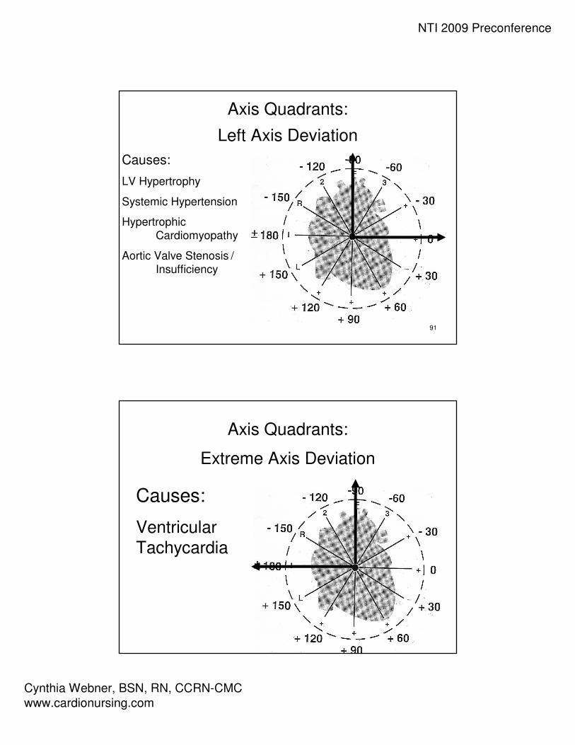
Axis Quadrants:
Left Axis Deviation
Causes:
LV Hypertrophy
Systemic Hypertension
Hypertrophic
Cardiomyopathy
Aortic Valve Stenosis /
Insufficiency
92
Axis Quadrants:
Extreme Axis Deviation
Causes:
Ventricular
Tachycardia

NTI 2009 Preconference
Cynthia Webner, BSN, RN, CCRN-CMC
www.cardionursing.com
93
Axis Quadrants:
Right Axis Deviation
Causes:
RV Hypertrophy
Pulmonary Hypertension
Pulmonic Valve Stenosis
Chronic Lung Disease
94
NTI 2009 Preconference
Cynthia Webner, BSN, RN, CCRN-CMC
www.cardionursing.com
95
96

NTI 2009 Preconference
Cynthia Webner, BSN, RN, CCRN-CMC
www.cardionursing.com
97
98
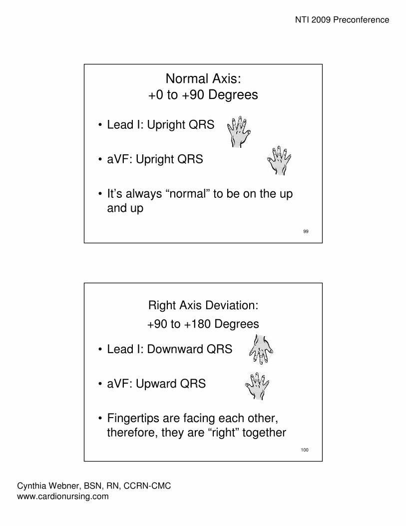
Let Your Hands Determine Axis
• Use Lead I and aVF
• Left hand represents QRS in Lead I
• Right hand represents QRS in aVF
• Fingertips will point in the same direction as the QRS complex
“Handy” Method of Axis Calculation developed by J. Cooper, PhD., American College of CV Nursing
NTI 2009 Preconference
Cynthia Webner, BSN, RN, CCRN-CMC
www.cardionursing.com
99
Normal Axis: +0 to +90 Degrees
• Lead I: Upright QRS
• aVF: Upright QRS
• It’s always “normal” to be on the up
and up
100
Right Axis Deviation:
+90 to +180 Degrees
• Lead I: Downward QRS
• aVF: Upward QRS
• Fingertips are facing each other,
therefore, they are “right” together

NTI 2009 Preconference
Cynthia Webner, BSN, RN, CCRN-CMC
www.cardionursing.com
101
Left Axis Deviation:
0 to –90 degrees
• Lead I: Upright QRS
• aVF: Downward QRS
• Fingertips are facing opposite
directions, therefore they are “left”
apart
102
Extreme Axis:
-90 to –180 Degrees
• Lead I: Downward QRS
• aVF: Downward QRS
• Fingertips are both facing downward
therefore the axis is down and out and
your fingers need to run for help
NTI 2009 Preconference
Cynthia Webner, BSN, RN, CCRN-CMC
www.cardionursing.com
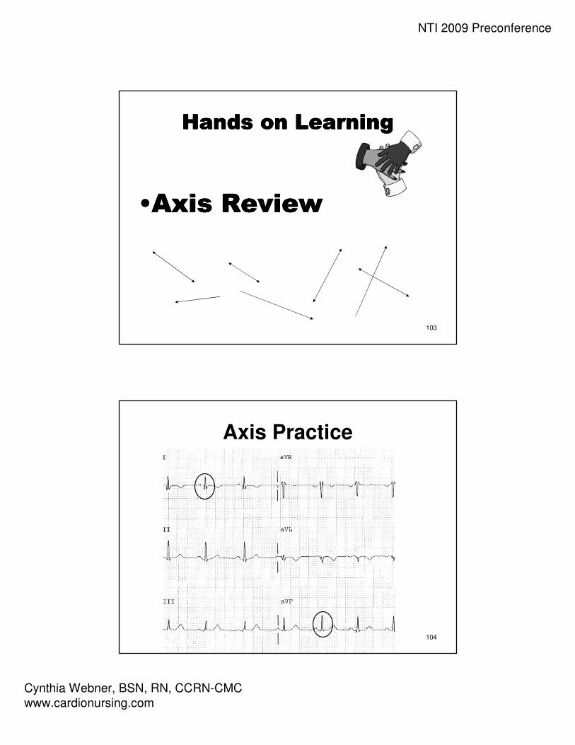
103
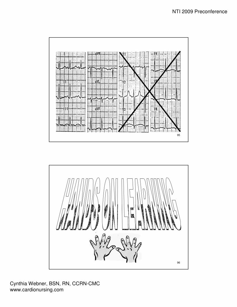
Hands on LearningHands on LearningHands on LearningHands on Learning
•Axis ReviewAxis ReviewAxis ReviewAxis Review
104
Axis Practice

NTI 2009 Preconference
Cynthia Webner, BSN, RN, CCRN-CMC
www.cardionursing.com
105
Axis Practice
106
Axis Practice

NTI 2009 Preconference
Cynthia Webner, BSN, RN, CCRN-CMC
www.cardionursing.com
107
Axis Practice
108
Calculating the Degree of Axis

NTI 2009 Preconference
Cynthia Webner, BSN, RN, CCRN-CMC
www.cardionursing.com
109
Calculating Degree of Axis “ESPN” Method – Step 1
• E=Equiphasic(First determine quadrant)
– Find the QRS complex in the limb leads which is the most equiphasic
OR
– Find the smallest QRS complex (height of R wave minus depth of S wave)
110
“ESPN” Method – Step 2
• S=Sister Lead
– Utilizing the “Criss-Cross”method Find the “Sister”lead to the lead with the most equiphasicQRS complex

NTI 2009 Preconference
Cynthia Webner, BSN, RN, CCRN-CMC
www.cardionursing.com
111
“ESPN” Method – Step 4
• If positive – locate the
positive pole of that lead
on the axis wheel to
determine degrees.
• If negative – locate the negative pole of that lead on the axis wheel to determine degrees.
112
Axis Practice
Calculating Degrees

NTI 2009 Preconference
Cynthia Webner, BSN, RN, CCRN-CMC
www.cardionursing.com
113
Calculate Degree of Axis
114
Calculate Degree of Axis
I
II
III

NTI 2009 Preconference
Cynthia Webner, BSN, RN, CCRN-CMC
www.cardionursing.com
115
Calculate Degree of Axis
116
Calculate Degree of Axis

NTI 2009 Preconference
Cynthia Webner, BSN, RN, CCRN-CMC
www.cardionursing.com
117
Lead 1Left Arm
High Lateral Wall
Axis Quadrant
aVRRight Arm
V14th ICS, RSB
Septal Wall
V4L MCL, 5th ICS
Anterior Wall
Lead 2Left Leg
Inferior Wall
aVLLeft Arm
High Lateral Wall
V24th ICS, LSB
Septal Wall
V5L anterior axillary,
same level as V4
Low Lateral Wall
Lead 3Left Leg
Inferior Wall
aVFLeft Leg
Inferior Wall
Axis Quadrant
V3Midway Between
V2 & V4
Anterior Wall
V6L midaxillary line,
same level as V4
Low Lateral Wall
118
ECG Fundamentals
Bundle Branch Blocks
NTI 2009 Preconference
Cynthia Webner, BSN, RN, CCRN-CMC
www.cardionursing.com
119
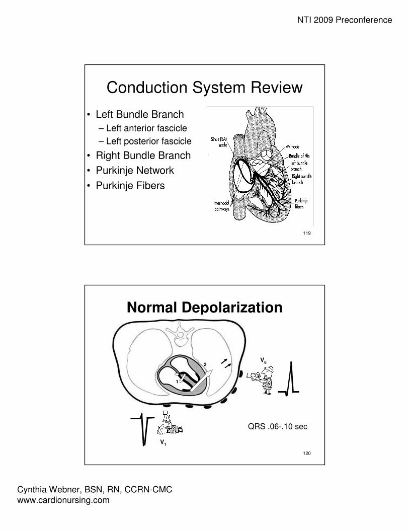
Conduction System Review
• Left Bundle Branch
– Left anterior fascicle
– Left posterior fascicle
• Right Bundle Branch
• Purkinje Network
• Purkinje Fibers
120
Normal Depolarization
V1
V6
QRS .06-.10 sec
1
2
NTI 2009 Preconference
Cynthia Webner, BSN, RN, CCRN-CMC
www.cardionursing.com
121
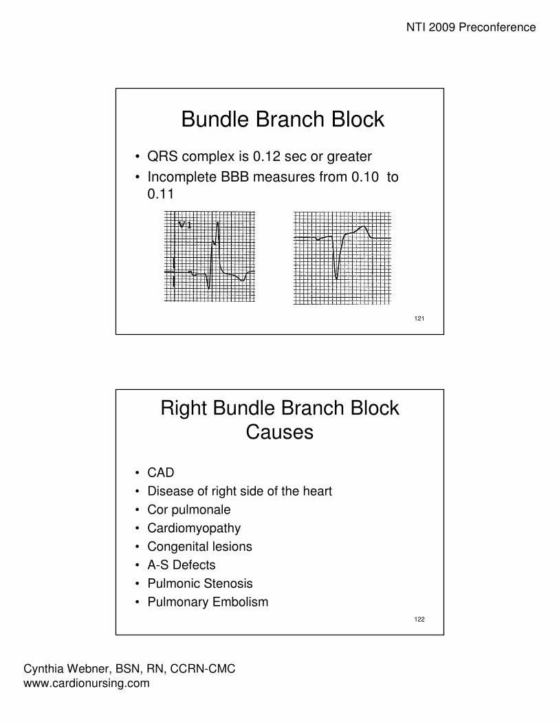
Bundle Branch Block
• QRS complex is 0.12 sec or greater
• Incomplete BBB measures from 0.10 to
0.11
122
Right Bundle Branch BlockCauses
• CAD
• Disease of right side of the heart
• Cor pulmonale
• Cardiomyopathy
• Congenital lesions
• A-S Defects
• Pulmonic Stenosis
• Pulmonary Embolism

NTI 2009 Preconference
Cynthia Webner, BSN, RN, CCRN-CMC
www.cardionursing.com
123
Normal Depolarization
V1
V6
QRS .06-.10 sec
1
2
124
Right Bundle Branch Block• V1
– Triphasic complex
rsR’ pattern - positive
– Or an M shaped R
wave with right peak
taller
– Or a qR pattern
• V6– Triphasic complex
– qRs with wide S waves
– Positive
V1V6
rSR’ qRs
V1
R qR

NTI 2009 Preconference
Cynthia Webner, BSN, RN, CCRN-CMC
www.cardionursing.com
125
Right Bundle Branch Block
• Secondary T wave changes: T wave should go in the opposite direction to the last part of the QRS complex –represents altered repolarization
• Primary T wave changes: T Waves that go in the
same direction as the last part of the QRS complex – indicate probable ischemia
126
Left Bundle Branch Block
Causes
• Left Ventricular Hypertrophy
• MI
• CAD
• Aortic Stenosis
• Cardiomyopathy
• Hypertensive cardiomyopathy

NTI 2009 Preconference
Cynthia Webner, BSN, RN, CCRN-CMC
www.cardionursing.com
127
Left Bundle Branch Block
V1 = QS
V6 = wide R
QRS = .12 sec or more
V1 = rS
128
Left Bundle Branch Block• V1
– Wide QS or rScomplex - negative
– Slick downstroke
– Nadir <0.06 sec
• V6– Wide R wave with
no initial septal q wave - - positive
V6

NTI 2009 Preconference
Cynthia Webner, BSN, RN, CCRN-CMC
www.cardionursing.com
129
Left Bundle Branch BlockNadir
• Measure from the
beginning of the
QRS complex to
the bottom valley
of the QRS
< 0.06 sec
130
Left Bundle Branch Block
Ischemia
• Secondary T wave changes: T waves
should be in the opposite direction from
the last part of the QRS complex –
represent altered repolarization
• Primary T wave Changes: T waves that
go in the same direction as the last part of
the QRS complex – represent probable
ischemia

NTI 2009 Preconference
Cynthia Webner, BSN, RN, CCRN-CMC
www.cardionursing.com
131
Left Bundle Branch Block
Injury
• An elevated J point is normal in the presence of a deep S wave as
long as ST remains concave – smile
• If ST becomes rounded then you may have
injury - frown
132
Left Bundle Branch Block
• Often have left axis deviation
• From normal to –60°
• Most often not more than –30°
• High mortality rate if left axis is present

NTI 2009 Preconference
Cynthia Webner, BSN, RN, CCRN-CMC
www.cardionursing.com
133
Left Anterior Hemiblock
Causes• Ischemia
• Valvular disease• Cardiomyopathy• Congenital heart disease• Rarely normal
• Blood supply received from septal branch of LAD (or AV nodal artery of RCA)
134
Left Anterior Hemiblock
• Block of anterior –superior fascicle of the LBB
• Left axis deviation– - 30°to –75°
– Become suspicious at -30°
– Definitive at – 40 to 45°
– Common at -60 °
• Commonly seen in anterior wall MI– Low mortality if
isolated
• Left anterior hemiblock in association with RBBB during AMI– Associated with left
main occlusion and high mortality
Key for recognizing -60°Axis
- aVR most equiphasic limb lead

NTI 2009 Preconference
Cynthia Webner, BSN, RN, CCRN-CMC
www.cardionursing.com
135
Left Anterior Hemiblock• Lead 2, Lead 3 and aVF
– rS pattern
– Small r waves
– Slightly wide / deep S waves
– Increased limb lead voltage
• Lead 1 and aVL
– qR pattern
• Normal QRS duration
136
Lead 1Left Arm
High Lateral Wall
Axis
aVRRight Arm
V14th ICS, RSB
Septal Wall
Right / Left BBB
V4L MCL, 5th ICS
Anterior Wall
Lead 2Left Leg
Inferior Wall
aVLLeft Arm
High Lateral Wall
V24th ICS, LSB
Septal Wall
V5L anterior axillary,
same level as V4
Low Lateral Wall
Lead 3Left Leg
Inferior Wall
aVFLeft Leg
Inferior Wall
Axis
V3Midway Between
V2 & V4
Anterior Wall
V6Low Lateral Wall
Right / Left BBB

NTI 2009 Preconference
Cynthia Webner, BSN, RN, CCRN-CMC
www.cardionursing.com
137
138

NTI 2009 Preconference
Cynthia Webner, BSN, RN, CCRN-CMC
www.cardionursing.com
139
140

NTI 2009 Preconference
Cynthia Webner, BSN, RN, CCRN-CMC
www.cardionursing.com
141
142
NTI 2009 Preconference
Cynthia Webner, BSN, RN, CCRN-CMC
www.cardionursing.com
143
144

NTI 2009 Preconference
Cynthia Webner, BSN, RN, CCRN-CMC
www.cardionursing.com
145
146