12 A Model-Based Mediator CHAPTER System for …users.sdsc.edu/~ludaesch/Paper/mbm-preprint.pdf ·...
36
Lacroix Lacroix-12 May 7, 2003 14:57 12 CHAPTER A Model-Based Mediator System for Scientific Data Management Bertram Lud ¨ ascher, Amarnath Gupta, Maryann E. Martone A database mediator system combines information from multiple existing source databases and creates a new virtual, mediated database that comprises the inte- grated entities and their relationships. When mediating scientific data, the techni- cally challenging problem of mediator query processing is further complicated by the complexity of the source data and the relationships between them. In partic- ular, one is often confronted with complex multiple-world scenarios in which the semantics of individual sources, as well as the knowledge to link them, require a deeper modeling than is offered by current database mediator systems. Based on experiences with federation of brain data, this chapter presents an extension called model-based mediation (MBM). In MBM, data sources export not only raw data and schema information but also conceptual models (CMs), including domain semantics, to the mediator, effectively lifting data sources to knowledge sources. This allows a mediation engineer to define integrated views based on (1) the local CMs of registered sources and (2) auxiliary domain knowledge sources called domain maps (DMs) and process maps (PMs), respectively, which act as sources of glue knowledge. For complex scientific data sources, semantically rich CMs are necessary to represent and reason with scientific rationale for linking a wide variety of heterogeneous experimental assumptions, observations, and con- clusions that together constitute an experimental study. This chapter illustrates the challenges using real-world examples from a complex neuroscience integra- tion problem and presents the methodology and some tools, in particular the knowledge-based integration of neuroscience data (KIND) mediator prototype for model-based mediation of scientific data.
Transcript of 12 A Model-Based Mediator CHAPTER System for …users.sdsc.edu/~ludaesch/Paper/mbm-preprint.pdf ·...

Lacroix Lacroix-12 May 7, 2003 14:57
12CHAPTER
A Model-Based MediatorSystem for Scientific Data
Management
Bertram Ludascher, Amarnath Gupta, Maryann E. Martone
A database mediator system combines information from multiple existing sourcedatabases and creates a new virtual, mediated database that comprises the inte-grated entities and their relationships. When mediating scientific data, the techni-cally challenging problem of mediator query processing is further complicated bythe complexity of the source data and the relationships between them. In partic-ular, one is often confronted with complex multiple-world scenarios in which thesemantics of individual sources, as well as the knowledge to link them, requirea deeper modeling than is offered by current database mediator systems. Basedon experiences with federation of brain data, this chapter presents an extensioncalled model-based mediation (MBM). In MBM, data sources export not onlyraw data and schema information but also conceptual models (CMs), includingdomain semantics, to the mediator, effectively lifting data sources to knowledgesources. This allows a mediation engineer to define integrated views based on (1)the local CMs of registered sources and (2) auxiliary domain knowledge sourcescalled domain maps (DMs) and process maps (PMs), respectively, which act assources of glue knowledge. For complex scientific data sources, semantically richCMs are necessary to represent and reason with scientific rationale for linking awide variety of heterogeneous experimental assumptions, observations, and con-clusions that together constitute an experimental study. This chapter illustratesthe challenges using real-world examples from a complex neuroscience integra-tion problem and presents the methodology and some tools, in particular theknowledge-based integration of neuroscience data (KIND) mediator prototypefor model-based mediation of scientific data.

Lacroix Lacroix-12 May 7, 2003 14:57
33612 A Model-Based Mediator System for Scientific Data Management
12.1 BACKGROUND
Seamless data access and sharing, handling of large amounts of data, federationand integration of heterogeneous data, distributed query processing and applica-tion integration, data mining, and visualization are among the common and recur-ring broad themes of scientific data management. A main stream of activity in thebioinformatics domain is concerned with sequence and structural databases suchas GenBank, Protein Data Bank (PDB), and Swiss-Prot, and much work is devotedto algorithmic challenges stemming from problems (e.g., efficient sequence align-ment and structure prediction). However, in addition to the well-known challengesof bioinformatics applications such as algorithmic complexity and scalability (e.g.,in genomics), there are other major challenges that are sometimes overlooked, par-ticularly when considering scientific data beyond the level of sequence and proteindata (e.g., brain imagery data). These challenges arise in the context of informationintegration of scientific data and have to do with the inherent semantic complex-ity of (1) the actual source data and (2) the glue knowledge necessary to link thesource data in meaningful ways. Traditional federated database system architec-tures, and those of the more recent database mediators developed by the databasecommunity, need to be extended to handle adequately information integration ofcomplex scientific data from multiple sources. This extension is a combination ofknowledge representation and mediator technology. In a nutshell:
Model-Based Mediation = Database Mediation + Knowledge Representation
With respect to their semantic heterogeneity (ignoring syntactic and systemaspects), information integration/mediation scenarios (scientific or otherwise) canbe roughly classified along a spectrum as follows: On one end, there are simpleone-world scenarios; somewhere in the middle are simple multiple-world scenar-ios; and at the other end of the spectrum are complex multiple-world scenarios.An example of a simple one-world scenario (i.e., in which the modeled real-worldentities can be related easily to one another and come from a single domain)is comparison shopping for books. A typical query is to find the cheapest pricefor a given book from a number of sources such as amazon.com and bn.com.An example of a simple multiple-world scenario is the integration of realtor andcensus data to annotate and rank real estate by neighborhood quality. Here, theapproach combines and relates quite different kinds of information, but the re-lations between the multiple worlds are simple enough to be understood withoutdeep domain knowledge. Examples of complex multiple-world scenarios are oftenfound in scientific data management and are the subject of this chapter. Thus,simple and complex here refer to the degree in which specific domain semantics

Lacroix Lacroix-12 May 7, 2003 14:57
12.1 Background337
is required to formalize or even state meaningful associations and linkages be-tween data objects of interest; it does not mean that the database and mediationtechnology for realizing such mediators is simple.1 For example, to state the prob-lem of what the result of an integrated comparison shopping view should be,a basic understanding of a books schema (title, authors, publisher, price, etc.)is sufficient. In particular, the association operation that links objects of inter-est across sources can be executed (at least in principle) as a syntactic join onthe ISBN. Similarly, in the realtor example, data can be joined based on ZIPcode, latitude and longitude, or street address (i.e., by spatial joins that can bemodeled as atomic function calls to a spatial oracle). To understand the basiclinkage of information objects, no insight into the details of the spatial join isrequired.
This is fundamentally different for complex multiple-world scenarios as foundin many scientific domains. There, even if data is stored in state-of-the-art (oftenWeb accessible) databases, significant domain knowledge is required to articulatemeaningful queries across disciplines (or within different micro-worlds of a singlediscipline); further examples are offered in the next section.
Outline
In this chapter, these challenges are illustrated with examples from ongoing col-laborations with users and providers of scientific data sets, in particular from theneuroscience domain (see Section 12.2). Then a methodology called model-basedmediation, which extends current database mediator technology by incorporatingknowledge representation (KR) techniques to create explicit representations of do-main experts’ knowledge that can be used in various ways by mediation engineersand by the MBM system itself, is presented in Section 12.3. The goal of MBMcould be paraphrased as:
Turning scientists’ questions into executable database queries.
Section 12.4 introduces some of the KR formalisms (e.g., for domain mapsand process maps) and describes their use in MBM. In Section 12.5 the KIND me-diator prototype and other tools being developed at the San Diego SupercomputerCenter (SDSC) and the University of California at San Diego (UCSD) are presentedprimarily in the context of the neuroscience domain. Section 12.6 discusses relatedwork and concludes the chapter.
1. Such simple mediation scenarios often pose very difficult technical challenges (e.g., query processingin the presence of limited source capabilities) [1, 2].

Lacroix Lacroix-12 May 7, 2003 14:57
33812 A Model-Based Mediator System for Scientific Data Management
12.2 SCIENTIFIC DATA INTEGRATION ACROSSMULTIPLE WORLDS: EXAMPLES ANDCHALLENGES FROM THE NEUROSCIENCES
Some of the challenges of scientific data integration in complex multiple-worldscenarios are illustrated using examples that involve different neuroscience worlds.Such examples occur regularly when trying to federate brain data across multiplesites, scales, and even species [3] and have led to new research and developmentprojects aimed at overcoming the current limitations of biomedical data sharingand mediation [4].
Example 12.2.1 (Two Neuroscience Worlds). Consider two neuro-science labora-tories, SYNAPSE and NCMIR2, that perform experiments on two different brainregions. The first laboratory, SYNAPSE, studies dendritic spines of pyramidal cellsin the hippocampus. The primary schema elements are thus the anatomical enti-ties reconstructed from 3D serial sections. For each entity (e.g., spines, dendrites),researchers make a number of measurements and study how these measurementschange across age and species under several experimental conditions.
In contrast, the NCMIR laboratory studies a different cell type, the Purkinjecells of the cerebellum. They inspect the branching patterns from the dendrites offilled neurons and the localization of various proteins in neuron compartments.The schema used by this group consists of a number of measurements of thedendrite branches (e.g., segment diameter) and the amount of different proteinsfound in each of these subdivisions. Assume each of the two schemas has a classC with a location attribute that has the value Pyramidal Cell dendrite andPurkinje Cell, respectively.
How are the schemas of SYNAPSE and NCMIR related? Evidently, they carrydistinctly different information and do not even enter the purview of the schemaconflicts usually studied in databases [5]. To the scientist, however, they are re-lated for the following reason: Like pyramidal neurons, Purkinje cells also possessdendritic spines. Release of calcium in spiny dendrites occurs as a result of neuro-transmission and causes changes in spine morphology (sizes and shapes obtainedfrom SYNAPSE). Propagation of calcium signals throughout a neuron depends onthe morphology of the dendrites, the distribution of calcium stored in a neuron,
2. Information about the two laboratories SYNAPSE and NCMIR is respectively available athttp://synapses.bu.edu and http://www-ncmir.ucsd.edu.

Lacroix Lacroix-12 May 7, 2003 14:57
12.2 Scientific Data Integration Across Multiple Worlds: Examples and Challenges339
and the distribution of calcium binding proteins, whose subcellular distributionfor Purkinje cells are measured by NCMIR.
Thus, a researcher who wanted to model the effects of neurotransmission inhippocampal spines would get structural information on hippocampal spines fromSYNAPSE and information about the types of calcium binding proteins foundin spines from NCMIR. Note that neither of the sources contains informationthat would allow a mediator system to bridge the semantic gap between them.Therefore, additional domain knowledge—independent of the observed experi-mental raw data of each source—is needed to connect the two sources. The domainexpert, here a neuroscientist, it is easy to provide the necessary glue knowledge
Purkinje cells and Pyramidal cells have dendrites that have higher-order branchesthat contain spines. Dendritic spines are ion (calcium) regulating components.Spines have ion binding proteins. Neurotransmission involves ionic activity(release). Ion-binding proteins control ion activity (propagation) in a cell. Ion-regulating components of cells affect ionic activity (release).
To capture such domain knowledge and make it available to the system, weemploy two kinds of ontologies, called domain maps and process maps, respec-tively. The former are aimed at capturing the basic domain terminology, and thelatter are used to model different process contexts. Ontologies, such as the do-main map in Figure 12.1, are often formalized in logic (in this case statementsin description logic [6]; see Section 12.4.1). Together with additional inferencerules (e.g., capturing transitivity of has), logic axioms like these formally capturethe domain knowledge and allow mediator systems to work with this knowl-edge (e.g., a concept or class hierarchy can be used to determine whether thesystem should retrieve objects of class C′ when the user is looking for instancesof C).
Domain maps not only provide a concept-oriented browsing and data explo-ration tool for the end user, but—even more importantly—they can be used fordefining and executing integrated view definitions (IVDs) at the mediator. Theprevious real-world example illustrates a fundamental difference in the natureof information integration as studied in most of the database literature and asis necessary for scientific data management. In the latter, seemingly unconnectedschema can be semantically close when situated in the scientific context, which,in this case, is the neuroanatomy and neurophysiological setting described previ-ously. Therefore, this is called mediation across multiple worlds and it is facilitatedusing domain maps such as the one shown (see Figure 12.1).
Unknown

Lacroix Lacroix-12 May 7, 2003 14:57
34012 A Model-Based Mediator System for Scientific Data Management
Branch
Shaft
Spine
has
Ion_Binding_Protein
contains
Ion_Regulating_Component
Compartment
Axon Dendrite Soma
has
Ion_Activity
Neurotransmission
subprocess
controls = , regulates
Neuron
has
AND
has
Spiny_Neuron
=
Purkinje_Cell Pyramidal_Cell
Protein
12.1
FIGURE
A domain map for SYNAPSE and NCMIR (left) and its formalization in descrip-tion logic (right). Unlabeled, gray edges ≈ “isa” ≈ “�”.
12.2.1 From Terminology and Static Knowledgeto Process Context
While domain maps are useful to put data into a terminological and thus some-what static knowledge context, a different knowledge representation has to bedevised when trying to put data into a dynamic or process context. Consider, forexample, groups of neuroscientists who study the science of mammalian memoryand learning. Many of these groups study a phenomena called long-term potentia-tion (LTP) in nerve cells, in which repeated or sustained input to nerves in specificbrain regions (such as the hippocampus) conditions them in such a manner thatafter some time, the neuron produces a large output even with a small amountof known input. Given this general commonality of purpose, however, individualscientists study and collect observational data for very different aspects of thephenomena.
Example 12.2.2(Capturing Process Knowledge). Consider a group [7] that studiesthe role of a specific protein N-Cadherin in the context of synapse formationduring late-phase long-term potentiation (L-LTP), a subprocess of LTP. The datacollected by the group consists of measurements that illustrate how the amount

Lacroix Lacroix-12 May 7, 2003 14:57
12.2 Scientific Data Integration Across Multiple Worlds: Examples and Challenges341
of N-Cadherin and the number of synapses (nerve junctions) both simultaneouslyincrease in cells during L-LTP. Now consider that a different group [8] studiesa new enzyme called CAMK-IV and its impact on a chemical reaction calledphosphorylation of a protein called CREB. Their data are collected to show howmodulating the amounts of CAMK-IV and other related enzymes affect the amountof CREB production, and how this, in turn, affects other products in the nucleus ofthe neurons. Ideally, the goal of mediating between experimental information fromthese two sources would be to produce an integrated view that enables an end-user scientist to get a deeper understanding of the LTP phenomena. Specifically, theend user should be able to ask queries (and get answers) that exploit the scientificinterrelationship between these experiments. In this way, the integrated accessprovided by a mediator system can lead to new observations and questions, thuseventually driving new experiments.
At the risk of oversimplification, the first group looks at synapse formationand is only interested in the fact that some proteins (including N-Cadherin) bringabout the formation of synapses. They do not look at the processes leading tothe production of these proteins. The second group looks at a specific chain ofevents leading up to the production of the proteins but does not identify whichproteins are produced. The semantic connection between these two sources canbe constructed in terms of the underlying event structure and the way the twogroups elaborate on different parts of it. Figure 12.2 depicts a simplified view ofthe relationship explained previously and shows the cyclic progression of eventsleading to synapse formation during LTP: Red edges situate the first source withrespect to the overall process, and blue edges situate the second source. In eithercase, the dashed lines show the subsequence of events the sources glossed over,or abstracted. Thus, the first source does not have any information pertaining tophosphorylates (CAMK-IV, CREB), and the second source does not have any datarelated to forms (protein, synapse). Neither source has any data about the (black)edge synthesizes (gene, protein).
Domain maps allow data providers to put their source data into a static/terminological context, and process maps allow them to do the same for a dy-namic/process context. Together, they capture valuable glue knowledge that residesat the mediator and facilitates integration of hard-to-correlate sources: in particu-lar, concept-oriented data discovery (semantic browsing) [9], view definition, andsemantic query optimization [10]. To make model-based mediation effective, it isalso necessary to hook the elements of the source schema to the domain map andthe process map. This process, which we call the contextualization mechanism, iscentral to the MBM framework.
Unknown

Lacroix Lacroix-12 May 7, 2003 14:57
34212 A Model-Based Mediator System for Scientific Data Management
0
1
r binitial_input
2
rbstarts(synapse_activity)
6
babstract_2
7
bforms(protein,synapse)
3
rbE-LTP
4
rb
sustained_input
5
bphosphorylates(CAMK-IV,CREB)
btranscribes(CREB,gene)
rabstract_1
synthesizes(gene,protein)
12.2
FIGURE
A simple process map. Blue and red edges (marked b and r , respectively) depictprocesses about which two data sources/research groups have observational data;dashed edges indicate abstractions (short cuts). No observational data is availablefor the edge 6–7; hence, this edge is shown in black.

Lacroix Lacroix-12 May 7, 2003 14:57
12.3 Model-Based Mediation343
12.3 MODEL-BASED MEDIATION
In mediator systems, differences in syntax and data models of sources S1, S2, . . .
are resolved by wrappers that translate the raw data into a common data format,typically extensible markup language (XML). In most current mediator systems,all other differences, in particular schema heterogeneities, are then handled by anappropriate integrated view definition (IVD), which is defined using an XML querylanguage [11, 12]. This architecture is extended by lifting exported source datafrom the level of uninterpreted, semistructured data in XML syntax to the seman-tically rich level of conceptual models (CMs) with domain knowledge. Then, themediator’s views can be defined in terms of CMs (i.e., IVDs are defined in a global-as-view fashion) and thus make use of a semantically richer model involving classhierarchies, complex object structure, and properties of relationships (relationalconstraints, cardinalities).
12.3.1 Model-Based Mediation: The Protagonists
The underlying methodology and procedures of MBM involve users in differentroles and at different levels:
✦ Data providers are typically domain experts, such as bench scientists whowould like to make their data from experimental studies available to the com-munity. In MBM, data providers can not only export an XML-queriable ver-sion of their data, but they can also export domain semantics by lifting the ex-ported data and schema information from a structural level (e.g., XML DTDs[Document Type Definitions]) to the level of CMs.3 Allowing data providersto situate or contextualize (see Section 12.3.5, Example 4) their primary datathemselves has significant benefits. First, data providers know best where theirdata fit on the glue maps. Second, even without the IVDs defined by mediationengineers, data are automatically associated across different sources via theirdomain/process map contexts.
✦ View providers specify integrated view definitions (IVDs), that is, they pro-gram complex views in an expressive, declarative rule language. The IVDsare defined over the registered complex sources CM(S1), CM(S2), . . . and theglue knowledge sources in the mediator’s repository. Thus, view providers are
3. The w3c working group XML Schema (http://www.w3.org/XML/Schema) and similar efforts likeRELAX NG (http://www.oasis-open.org/committees/relax-ng/) play an intermediate role betweenpurely structure-based models (DTDs) and richer semantic models with constraint mechanisms.

Lacroix Lacroix-12 May 7, 2003 14:57
34412 A Model-Based Mediator System for Scientific Data Management
the actual mediation engineers and they bring together (as a team or individ-ually) expertise in the application domain and in databases and knowledgerepresentation.
The new fused objects defined by an IVD can be contextualized, basedon the contexts provided by the source conceptual models (see right side ofFigure 12.6). In this way, an integrated, virtual view exported by the mediatorbecomes a first-class citizen of the federation; it is considered a conceptuallevel source CM(M) itself and can be used just like any original CM-wrappedsource.
✦ End users can start with semantic browsing of CMs, by navigating the domainand process ontologies in the style of topic maps, in which a user navigatesthrough a concept space by following certain relationships, going up and downconcept hierarchies and so on. Users may also focus their view by issuinggraph queries over domain or process maps, which return only the subgraphsof interest. Eventually, the user can access raw data from different sources,which is (due to contextualization) automatically organized by context [9],and access derived data resulting from user queries against the mediated views.
12.3.2 Conceptual Models and Registration of Sourcesat the Mediator
The following components of the conceptual model CM of a source S can bedistinguished:
CM(S) = OM(S) ∪ ONT(S) ∪ CON(S)
The different logical components and their dependencies are depicted inFigure 12.3:
✦ OM(S) is the object model of the source S and provides signatures for classes,associations between classes, and functions. OM(S) structures can be definedextensionally by facts (EDB), or intensionally via rules (IDB).
✦ ONT(S) is the local ontology of the source S. It defines concepts and theirrelationships from the source’s perspective.
✦ ONTG(S) is the ontological grounding of OM(S) in ONT(S), that is, a map-ping between the object model OM(S) (classes, attributes, associations) andthe concepts and relationships of ONT(S).
✦ CON(S) is the contextualization of the local source ontology relative to amediator ontology, ONT(M).

Lacroix Lacroix-12 May 7, 2003 14:57
12.3 Model-Based Mediation345
Object ModelOM(S)
IDB(S) EDB(S)
Source OntologyONT(S)
Conceptual ModelCM(S)
Contextualization CON(S) in CSL
Ontological GroundingONTG(S)
Mediator OntologyONT(M)
Integrated View DefinitionIVD(M)
GAV
LAV
12.3
FIGURE
Model-based mediation: dependencies among logical components.
✦ IVD(M) is the mediator’s integrated view definition and comprises logic viewdefinitions in terms of the sources’ object models OM(S) and the mediator’sontology ONT(M). By posing queries against the mediator’s IVD(M), the userhas the illusion of interacting with a single, semantically integrated sourceinstead of interacting with independent, unrelated sources.
In the following, the local parts of CM(S) (OM(S), ONT(S), and ONTG(S))are presented through a running example. For details on the contextualizationCON(S) see Example 4 and the related work on registering scientific data sources[13].
Example 12.3.1 (Cell-Centered Database [CCDB]). Figure 12.4 shows piecesof a simplified version of the conceptual model CM(CCDB) of a real-world sci-entific information source called the Cell-Centered Database [14]. The databaseconsists of a set of EXPERIMENTS objects. Each experiment collects a numberof cell IMAGES from one or more instruments. For each image, the scientistsmark out cellular STRUCTURES in the image and perform measurements on them[14]. They also identify a second set of regions, called DEPOSITs, in images thatshow the deposition of molecules of proteins or genetic markers. In general, aregion marked as deposit does not necessarily coincide with a region marked as astructure.

Lacroix Lacroix-12 May 7, 2003 14:57
34612 A Model-Based Mediator System for Scientific Data Management
12.4
FIGURE
Conceptual model for registering the Cell-Centered Database [14].
Lacroix Lacroix-12 May 7, 2003 14:57
12.3 Model-Based Mediation347
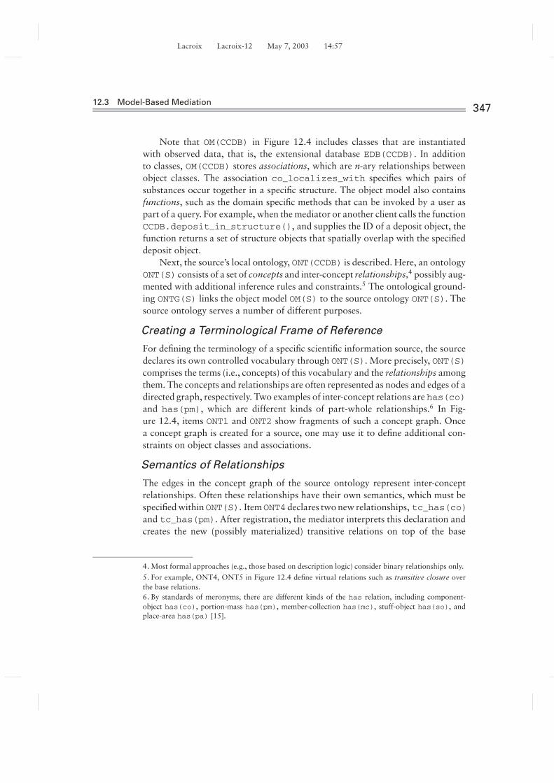
Note that OM(CCDB) in Figure 12.4 includes classes that are instantiatedwith observed data, that is, the extensional database EDB(CCDB). In additionto classes, OM(CCDB) stores associations, which are n-ary relationships betweenobject classes. The association co_localizes_with specifies which pairs ofsubstances occur together in a specific structure. The object model also containsfunctions, such as the domain specific methods that can be invoked by a user aspart of a query. For example, when the mediator or another client calls the functionCCDB.deposit_in_structure(), and supplies the ID of a deposit object, thefunction returns a set of structure objects that spatially overlap with the specifieddeposit object.
Next, the source’s local ontology, ONT(CCDB) is described. Here, an ontologyONT(S) consists of a set of concepts and inter-concept relationships,4 possibly aug-mented with additional inference rules and constraints.5 The ontological ground-ing ONTG(S) links the object model OM(S) to the source ontology ONT(S). Thesource ontology serves a number of different purposes.
Creating a Terminological Frame of Reference
For defining the terminology of a specific scientific information source, the sourcedeclares its own controlled vocabulary through ONT(S). More precisely, ONT(S)comprises the terms (i.e., concepts) of this vocabulary and the relationships amongthem. The concepts and relationships are often represented as nodes and edges of adirected graph, respectively. Two examples of inter-concept relations are has(co)and has(pm), which are different kinds of part-whole relationships.6 In Fig-ure 12.4, items ONT1 and ONT2 show fragments of such a concept graph. Oncea concept graph is created for a source, one may use it to define additional con-straints on object classes and associations.
Semantics of Relationships
The edges in the concept graph of the source ontology represent inter-conceptrelationships. Often these relationships have their own semantics, which must bespecified withinONT(S). ItemONT4 declares two new relationships, tc_has(co)and tc_has(pm). After registration, the mediator interprets this declaration andcreates the new (possibly materialized) transitive relations on top of the base
4. Most formal approaches (e.g., those based on description logic) consider binary relationships only.
5. For example, ONT4, ONT5 in Figure 12.4 define virtual relations such as transitive closure overthe base relations.6. By standards of meronyms, there are different kinds of the has relation, including component-object has(co), portion-mass has(pm), member-collection has(mc), stuff-object has(so), andplace-area has(pa) [15].

Lacroix Lacroix-12 May 7, 2003 14:57
34812 A Model-Based Mediator System for Scientific Data Management
relations has(co) and has(pm) provided by the source S. Similarly, the itemONT5 is interpreted by the mediator using a higher-order rule for chaining binaryrelations:
chain(R1,R2)(X,Y) if R1(X,Z), R2(Z,Y)
With this, ONT5 creates a new relationship has_co_pm(X,Y) provided that thereis a Z such that tc_has(co)(X,Z), and tc_has(pm)(Z,Y).
Ontological Grounding of OM(S)
A local domain constraint specifies additional properties of the given extensionaldatabase and thereby establishes an ontological grounding ONTG(S) between thelocal ontology ONT(S) and the object model OM(S) (see Figure 12.3). Items OG1–OG2 in Figure 12.4 refine the domains of the attributes EXPERIMENT.cell_typeand STRUCTURE.name from the original type declaration (STRING). The refine-ment constrains them to take values from those nodes of the concept graph thatare descendants of the concept cerebellum through the has(co) relationship.
This constraint illustrates an important role of the local ontology in a concep-tually lifted source. By constraining the domain of an attribute to be concept name,C, the corresponding object instance o is semantically about C. In addition, thisalso implies that o is about any ancestor concept, C', of C where ancestor is de-fined via has(co) edges only. Similarly, if a specific instance, STRUCTURE.name,has the value spine process, it is also about dendrite (ONT2 in Figure 12.4).
In addition to linking attributes to concept names, a constraint may also in-volve inter-concept relationships. Assume projects_to(cell, brain_region) is a relationship in the source ontology ONT(CCDB). A constraint mayassert that for all instances e of class EXPERIMENT, projects_to(e.cell_type, 'globus_pallidus') holds (OG3). The constraint thus refines theoriginal relationship projects_to to suit the specific semantics of OM(CCDB).Such constraint-defined correspondences between OM(S) and ONT(S) are usedin the contextualization process [13].
Intensional Definitions
In the CM wrapper of a source, S, we can define virtual classes and associationsthat can be exported to the mediator as first-class, queriable items by means ofan intensional database IDB(S). For example, we can create a new virtual classAu: s/b
“Intensional”? called DENATURED_PROTEIN in IDB(CCDB) via the rule:
DENATURED_PROTEIN(ProtName) if DEPOSIT(ID, ProtName,
protein, dark, _, _),deposit_in_structure(ID) �= ∅
Unknown
Unknown

Lacroix Lacroix-12 May 7, 2003 14:57
12.3 Model-Based Mediation349
Thus, an instance of a DENATURED_PROTEIN is created when a dark proteindeposit is recorded in an instance of DEPOSIT and there is some structure inwhich this deposit is found. As a general principle of creating a CM wrapper,such a definition will be supplemented by additional constraints to connect itto the local ontology. For example, assume that ONT(CCDB) already contains aconcept called process. Item ONT3 defines denaturation as a specializationof process. The constraint OG4 completes the semantic specification about thenew DENATURED_PROTEIN object.
Contextual References
It is a common practice for scientific data sources to tag object instances withattributes from a public standard and to use controlled vocabularies for the valuesof some of these attributes. For example, the source can specify that the domainof the DEPOSIT.id field can be accessed through an internal method, which,given a protein name, gets its id from a specific database. For example, we canuse get_expasy_protein_id to retrieve this information from the Swiss-Protdatabase on the Web. How the source enforces this integrity constraint is internalto the source and not part of its conceptual export schema.
12.3.3 Interplay between Mediator and Sources
To address the source registration issue, which components of an existing n-sourcefederation that can be seen, or accessed, by the new, n+1st source need to be spec-ified. A federation at the mediator consists of: (1) currently registered conceptualmodels CM(S) of each participating source S, (2) one or more global ontologiesONT(M) residing at the mediator that have been used in the federation, and (3)integrated views IVD(M) defined in a global-as-view (GAV) fashion.
Typical mediator ontologies ONT(M) are public, meaning they serve asdomain-specific expert knowledge and thus can be used to glue conceptual modelsfrom multiple sources. Examples of such ontologies are the Unified Medical Lan-guage System (UMLS) from the National Library of Medicine7 and the BiologicalProcess Ontology from the Gene Ontology Consortium.8 In the presence of multi-ple ontologies, articulations, (mappings between different source ontologies [16])
7. The Unified Medical Language System (UMLS) available at http://www.nlm.nih.gov/research/umls/is, strictly speaking, a metathesaurus, or a semi-formal ontology with a limited set of pre-definedrelationships such as broader-term/narrower-term.8. See http://www.geneontology.org/process.ontology for information about the Biological Processfrom the Gene Ontology Consortium.
Unknown

Lacroix Lacroix-12 May 7, 2003 14:57
35012 A Model-Based Mediator System for Scientific Data Management
Neostriatum
Medium_Spiny_Neuron
has
OR GABA
exp
Substance_P
exp
Dopamine_R
exp
Neuron
Spiny_Neuron
Compartment
has
DendriteAxonSoma
Substantia_nigra_pr
proj
Substantia_nigra_pc
proj
Globus_Pallidus_External
proj
Globus_Pallidus_Internal
proj
Neurotransmitter
MyNeuron
proj
MyDendrite
ALL: has
AND
=
exp
12.5
FIGURE
A domain map (DM) after situating new concepts MyNeuron and MyDendrite(dark).
can be used to register with the mediator information about inter-source relation-ships. Note that a source, S, usually cannot see all of the previously discussedcomponents (1–3) when defining its conceptual model: Although S sees the medi-ator’s ontologies, ONT(M), and thus can define its own conceptual model, CM(S),relative to the mediator’s ontology in a local-as-view (LAV) fashion, it cannot di-rectly employ another source’s conceptual model, CM(S'), nor can it query themediator’s integrated view, IVD(M), which is defined global-as-view (GAV) ontop of the sources. The former is no restriction because S' can register CM(S'),in particular ONT(S'), with the mediator, at which point S can indirectly refer toregistered concepts of S' via ONT(M). The latter guarantees that query processingin this setting does not involve recursion through the Web (i.e., between a sourceS and the mediator M). The dependency graph in Figure 12.3 is acyclic.9
Example 12.3.2 (Contextualization: Local-as-View). Consider the domainmap in Figure 12.5. Lighter-colored nodes correspond to concepts that the me-diator understands and a source can see. Now assume a source, S, wants to reg-ister information about specific neurons and their dendrites, but the mediatorontology (domain map) does not have dedicated names for those specific kindsof neurons and dendrites. In MBM this problem is solved by contextualizing
9. At the cost of loss of efficiency, the restriction no recursion through the Web could be lifted.

Lacroix Lacroix-12 May 7, 2003 14:57
12.4 Knowledge Representation for Model-Based Mediation351
the new local source concepts as views on the mediator’s global concepts: InFigure 12.5, the darker-colored source concepts are hooked to the mediator’sdomain map, thereby defining their meaning relative to the mediator’s concepts.This is achieved by sending the following first-order axioms (here in descriptionlogic syntax) to the mediator:
MyDendrite ≡ Dendrite � ∃exp.Dopamine_RMyNeuron � Medium_Spiny_Neuron
� ∃proj.Globus_pallidus_external� ∀has.MyDendrite
Thus instances of MyDendrite are exactly those dendrites that express Dopa-mine R(eceptor), and MyNeuron objects are medium spiny neurons projectingto Globus Pallidus External and only have MyDendrites. Assuming propertiesare inherited along the transitive closure of isa, it follows that MyNeuron, likeany Medium_Spiny_Neuron projects to certain structures (OR in Figure 12.5).With the newly registered knowledge, it follows that MyNeuron definitely projectsto Globus Pallidus External. To specify that it only projects to the latter, a non-monotonic inheritance (e.g., using F-logic (FL) with well-founded semantics) canbe employed.
Note that the intuitive graphical contextualization depicted in Figure 12.5is not unique; logically equivalent domain maps may have different graphicalrepresentations.10 For domain maps that can be completely axiomatized using adescription logic, a reasoning system such as Fast Classification of Terminologies(FaCT) [17] can be employed to compute the deductive closure and, in particular,to derive a unique concept hierarchy and check consistency of a domain map.
12.4 KNOWLEDGE REPRESENTATION FORMODEL-BASED MEDIATION
This section takes a closer look at the principal mechanisms for specifying glueknowledge: ontologies in the form of domain maps (DMs) and process maps(PMs).
10.This is similar to the fact that the same query can have many different syntactic representations. Ingeneral, equivalence of first-order (or SQL) queries is not decidable.

Lacroix Lacroix-12 May 7, 2003 14:57
35212 A Model-Based Mediator System for Scientific Data Management
12.4.1 Domain Maps
As is standard for ontologies, DMs name and specify relevant concepts by describ-ing the characteristic relationships among them [18]. In this way, DMs provide thebasic domain semantics needed to glue data across different sources in multiple-world scenarios. DMs can be depicted more intuitively in the form of labeled,directed graphs. In contrast to many other graph-based notations, however, DMshave a solid formal semantics via a translation to logic rules. The graph form ofDMs is defined as follows.
Definition 12.1 Domain Maps
Let C be a set of symbols called concepts and R a set of roles. A DM is a directed,labeled graph with nodes C. A concept C ∈ C can be understood as denoting aclass of objects sharing a set of common properties. To understand how a conceptC is defined relative to other concepts, we have to inspect its outgoing edges. c ∈ Cdenotes that c is an instance of concept C.11 Edges are distinguished in DMs asfollows:
1. Cisa→ D (short: C → D) defines that every C isa D, that is, c ∈ C implies
c ∈ D.The subconcept/subclass relation is very common in DMs, thus the isa labelis usually omitted and the shorthand notation C → D is used instead.
2. Cex:r→ D defines that for every c ∈ C, there exists some r -related d ∈ D.
Here, r ∈ R is a role, or, a binary relation r (c, d) between instances of C andD.
3. Call:r→ D defines that for every c ∈ C and all x that are r -related to c (i.e., for
which r (c, x) holds), x ∈ D holds.
4. Cr→ D defines that if c ∈ C and d ∈ D, then they are r -related, that is, r (c, d)
holds.
5. AND→i {D1, . . . , Dn} indicates that an AND-node with n outgoing edges toD1, . . . , Dn, respectively, defines an anonymous concept, the intersection ofconcepts D1, . . . , Dn.
6. OR→i {D1, . . . , Dn}, indicates that an OR-node with n outgoing edges toD1, . . . , Dn, respectively, defines an anonymous concept, the union of con-cepts D1, . . . , Dn.
11.Thus, C and D can be viewed as unary predicates.
Unknown

Lacroix Lacroix-12 May 7, 2003 14:57
12.4 Knowledge Representation for Model-Based Mediation353
7. C=→ Ddefines that C is equivalent to D, meaning every C isa Dand vice versa.
We could have denoted this also as C↔D. However, the directed edge keepsthe distinction between C (the definiendum) and its definition D (definiens).
Note that D can be an atomic or a defined concept. When unique, AND nodesare omitted and outgoing arcs directly attached to the concept being defined. InFigure 12.5, unlabeled, grey edges and edges labeled proj (projects-to) correspondto isa edges and ex:proj edges, respectively.
Reified Roles as Concepts
In DMs, as in description logics, the concepts are being defined, whereas the rolesare only a means to that end. To capture the semantics of roles, or define theirproperties in terms of each other, they need to be defined in terms of conceptsthemselves. In logic, this “quoting mechanism” is known as reification.
Example 12.4.1 (Roles as Concepts). Consider a DM involving the roles reg-ulates, activates, and inhibits, and assume that in the given domain, activates(C, D) and inhibits (C, D) are special cases of regulates (C, D). Instead of in-troducing a special notation for sub-roles12 and then defining the mechanics ofhow roles can be related to one another, roles are turned into first-class citizensby making them concepts using an operator, make-concept (mc). The modelingcapabilities of DMs can be applied to roles and, for example, simply state thatmc(activates)
isa→mc(regulates).
By modeling roles as concepts, more domain semantics can be formalized,leading to better knowledge engineering. In particular, during query processing,such formalized knowledge can be automatically employed by the system: Givena DM (formalized as logic rules), an MBM query or view definition involvingactivates and regulates knows that the former is a subconcept of the latter. Ifduring query processing a goal regulates('cAMP',Protein) is evaluated,the logic rules corresponding to the DM knowledge allow the system to deducethat any result for activates('cAMP',Protein) is also an answer for reg-ulates('cAMP',Protein). This is correct because a substitutability principleholds, which allows the system to replace a concept, D, with any of its subconcepts,C, that is, for which C
isa→ D holds.
12.RDF(S) has such a notion called subproperty; see http://www.w3.org/TR/rdf-schema/.
Unknown

Lacroix Lacroix-12 May 7, 2003 14:57
35412 A Model-Based Mediator System for Scientific Data Management
Generating the Role Hierarchy
When making a role into a concept, the isa hierarchy13 on concepts induces an isahierarchy on roles.
Domain Maps as Logic Rules
Domain maps borrow from description logics [19] the notions of concept androles. Indeed, while some of the previously mentioned constructs of DMs haveequivalent formalizations in description logic [20], the fact that we need additionalmechanisms such as roles as concepts and recursive and parameterized roles andconcepts, and the fact that we want executable DMs during query processing,requires a translation into a more general logic framework.
In the following, we formalize DMs in a minimal subset of FL [21]. Thesemantics of DMs could be formalized in other languages, in particular in otherdeductive database languages. The use of FL is convenient because a small subsetof it already matches nicely the minimal requirements established for a MBMsystem [20]. Moreover, implementations of FL are readily available [22, 23] andhave been used by the authors in different mediator prototypes before [24, 25, 26].
In FL, c : C and C :: D denote class membership (c ∈ C) and subclassing(C ⊆ D), respectively. Thus, there are logic rules of the form head if body thatexpress the FL semantics of “:” and “::”. Say that “::” is a reflexive, transitive,and antisymmetric14 relation.
Definition 12.2 Compilation of Domain Maps
The mapping � : DM → FL of domain maps to F-logic is defined as follows:
1. �(C) := {C : concept}, for all atomic concepts C ∈ C2. �(r ) := {r : role}, for all roles r ∈ R3. �(C
isa→ D) := {C :: �D} ∪ �(D)
4. �(Cex:r→ D) :=
(a) {r (c, _d), _d : �D if c : C, _d = skolD(c)} ∪ �(D)
(b) {F alse if c : C, ¬(r (c, _d), _d : �D))} ∪ �(D)
5. �(Call:r→ D) :=
(a) {d : �D if c : C, r (c, d)} ∪ �(D)
(b) {F alse if c : C, r (c, d), ¬d : �(D)} ∪ �(D)
13.Strictly speaking, the isa does not have to be a hierarchy but can be any directed acyclic graph.
14.Because concepts are implemented as FL classes, this avoids terminological cycles.
Unknown
Unknown
Unknown

Lacroix Lacroix-12 May 7, 2003 14:57
12.4 Knowledge Representation for Model-Based Mediation355
6. �(Cr→ D) := {r (c, d) if c : C, d : �(D)} ∪ �(D)
7. �(AND→i {D1, . . . , Dn}) := {d : skolAND if d : �(D1), . . . , d :�(Dn)} ∪ �(D1) ∪ · · · ∪ �(Dn)
8. �(OR→i {D1, . . . , Dn}) := {d : skolOR if d : �(D1) ∨ . . . ∨ d :�(Dn)} ∪ �(D1) ∪ · · · ∪ �(Dn)
9. �(C=→ D) := {C :: �(D), �(D) :: C if �(D)} ∪ �(D)
Remarks
Here, �(D) is defined similar to �(D), but it returns for a compound con-cept description D, a new auxiliary symbol �(D) representing the compound.For atomic D, we simply have �(D) = �(D). The symbols skolX produce newSkolem function symbols every time they are used in the translation �: Forexample, in 4(a), we invent a symbolic representation for the existentially quan-tified variable _d. Note that c, d, _d are logic variables, while C,D,Di ,False areconstants.15 The different variants (a) and (b) in the translations of DMs corre-spond to different intended uses: in 4(a), we create an anonymous object for the∃-quantified variable, in 5(a), we type coerce all C.r objects into instances of D.In contrast, the (b) translations only check whether the constraints induced bythe DM edges are indeed satisfied and signal an inconsistency (False) if they arenot.
Example 12.4.2 Roles as Concepts Continued. Consider a DM stating thatNProt
isa→ Protein, NProt regulates some Gene, and cfosisa→ Gene.16
The role regulates is conceptualized by asserting mc(regulates). When makingits hidden arguments visible, mc(regulates (C,D)) really denotes a family ofregulates concepts. The isa hierarchy on regulates concepts is derived fromthe isa hierarchy of its arguments. For example:
mc(regulates(NProt,cfos))isa→ mc(regulates(NProt, Gene))
isa→ mc(regulates(Protein, Gene))
Deriving the Role Hierarchy
Previously the unary operator, mc, which turns role literals into concepts wasintroduced. It is implemented in FL as a subclass of the (meta-)class concept byasserting mc::concept and adding further rules for deriving the role hierarchy
15.This is reversed from the usual convention used in the rest of the chapter to match our DM notation.
16.Here, NProt stands for nuclear protein.
Unknown
Unknown
Unknown
Lacroix Lacroix-12 May 7, 2003 14:57
35612 A Model-Based Mediator System for Scientific Data Management
from the concept hierarchy, which are given as set of mc-declarations such asr(C, D) : mc by the user:
r(C,D): mc, r(C',D'): mc, r(C,D)::r(C',D')
if (r(C,D): mc ∨ r(C',D'): mc),C:: C', D:: D' (up/down)
r(C,D): mc, r(C',D'): mc, r(C,D):: r(C',D')
if (r(C,D'): mc ∨ r(C',D): mc), C:: C', D::D' (mixed)
Observe that with these rules, the desired result is obtained in Example 6.
Recursive Concepts
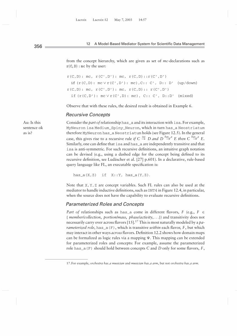
Consider the part of relationship has_a and its interaction with isa. For example,Au: Is thissentence okas is?
MyNeuron isa Medium_Spiny_Neuron, which in turn has_a Neostriatumtherefore MyNeuron has_a Neostriatum holds (see Figure 12.5). In the general
case, this gives rise to a recursive rule if Cisa→ D and D
has_a→ E then Chas_a→ E.
Similarly, one can define that isa and has_a are independently transitive and thatisa is anti-symmetric. For such recursive definitions, an intuitive graph notationcan be devised (e.g., using a dashed edge for the concept being defined to itsrecursive definition, see Ludascher et al. [27] p.601). In a declarative, rule-basedquery language like FL, an executable specification is:
has_a(X,Z) if X::Y, has_a(Y,Z).
Note that X,Y,Z are concept variables. Such FL rules can also be used at themediator to handle inductive definitions, such as ONT4 in Figure 12.4, in particular,when the source does not have the capability to evaluate recursive definitions.
Parameterized Roles and Concepts
Part of relationships such as has_a come in different flavors, F (e.g., F ∈{ member/collection, portion/mass, phase/activity, . . .}) and transitivity does notnecessarily carry over across flavors [15].17 This is most naturally modeled by a pa-rameterized role, has_a(F), which is transitive within each flavor, F , but whichmay interact in other ways across flavors. Definition 12.2 shows how domain mapscan be formalized as logic rules via a mapping �. This mapping can be extendedfor parameterized roles and concepts: For example, assume the parameterizedrole has_a(F) should hold between concepts C and D only for some flavors, F ,
17.For example, orchestra has a musician and musician has a arm, but not orchestra has a arm.

Lacroix Lacroix-12 May 7, 2003 14:57
12.4 Knowledge Representation for Model-Based Mediation357
satisfying a condition ϕ(F ). We can extend � and compile such a parameterizedDM edge into FL as follows:
�(Chas_a(F)‖ϕ(F)−→ D) = {has_a(F)c,d if c: C,d:�(D),ϕ(F)} ∪ �(D)
Note that a parameterized role such as has_a(F) has a first-order semantics inFL despite its higher-order syntax [28].
12.4.2 Process Maps
PMs provide abstractions of process knowledge, that is, temporal and/or causalrelationships between events that can be used for situating and linking data acrossdifferent sources. Like DMs, PMs are directed, labeled graphs, albeit with a verydifferent semantics: Nodes are used to model states and edges correspond to statetransitions, which are labeled with a process name describing the transition. Inthis way, data providers (e.g., bench scientists) can not only hook their raw datato the (given or refined) DMs but also to processes witnessed in their experimentalstudies databases (see Figure 12.2 and Figure 12.8).
Initial Process Semantics PM0
Intuitively, an edge of the form eπ = s{ϕ}π{ψ}−→ s ′ of a PM means that the process π
leads from state s to s ′; ϕ is a necessary precondition that must hold in s for π tohappen, and ψ is a postcondition, which holds in s ′ as a result of π . P M0 denotesthe set of all initial process semantics.
We call the edge eπ of a PM a process occurrence of π in PM. Thus, a processoccurrence specifies where in a PM a process occurs, and which pre- and postcon-ditions, ϕ and ψ , this occurrence satisfies. In addition to the semantics implied bythe occurrence of eπ in PM, a process π can have an initial semantics associatedwith the process name, π .
To allow for parameterization of processes, edge labels where process namesare first-order atoms (of the form π = π(T1, . . . , Tn) where each term Ti is a logicvariable or constant) are considered. For example, consider π =opens(Channel)as describing the opening process of an ion channel. Its initial semantics are definedby the expression:
{¬open(Channel)} opens(Channel) {open(Channel)}
meaning that any transition along a process occurrence of π = opens(Channel)in a PM must be from a state where open(Channel) was false. In the successorstate, however, (after π has happened), open(Channel) is true.
Unknown
Unknown
Lacroix Lacroix-12 May 7, 2003 14:57
35812 A Model-Based Mediator System for Scientific Data Management
From Process Maps to Domain Maps
The first-order predicates occurring in ϕ and ψ are called open(Channel), fluents,because their truth is state dependent. It is required that the set of fluent predicatesymbols, F , is disjointed from the set, P, of process names and the sets of conceptand role names C and R, respectively. In contrast, the constant parameters usedin process occurrences, such as Channel are allowed to be concepts from C.
For example, a DM may have that NMDA_receptorisa→ Calcium_channel
isa→channel in which case the process knowledge about the opening of channelsand the static knowledge from a DM are directly linked through the commonconcept Channel.
Similarly, just as roles are first-class citizens by reifying them into concepts, thesame can be done for processes, by specifying additional semantics of processesusing domain maps.
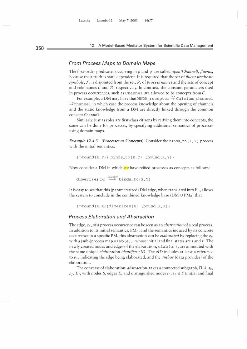
Example 12.4.3 (Processes as Concepts). Consider the binds_to(X,Y) processwith the initial semantics.
{¬bound(X,Y)} binds_to(X,Y) {bound(X,Y)}
Now consider a DM in which we have reified processes as concepts as follows:
dimerizes(X)isa‖X=Y−→ binds_to(X,Y)
It is easy to see that this (parameterized) DM edge, when translated into FL, allowsthe system to conclude in the combined knowledge base (DM ∪ PM0) that
{¬bound(X,X)}dimerizes(X) {bound(X,X)}.
Process Elaboration and Abstraction
The edge, eπ , of a process occurrence can be seen as an abstraction of a real process.In addition to its initial semantics, PM0, and the semantics induced by its concreteoccurrence in a specific PM, this abstraction can be elaborated by replacing the eπ
with a (sub-)process map elab(eπ), whose initial and final states are s and s ′. Thenewly created nodes and edges of the elaboration, elab(eπ), are annotated withthe same unique elaboration identifier eID. The eID includes at least a referenceto eπ , indicating the edge being elaborated, and the author (data provider) of theelaboration.
The converse of elaboration, abstraction, takes a connected subgraph, �(S, s0,s f , E), with nodes S, edges E, and distinguished nodes s0, s f ∈ S (initial and final
Unknown

Lacroix Lacroix-12 May 7, 2003 14:57
12.4 Knowledge Representation for Model-Based Mediation359
state), and abstracts � into a single edge eπ = abstract(�(S,s0,sf,E)).The abstracted edges E of � are marked with a unique abstraction identifier aID,which includes a reference to the new abstraction edge, eπ , and the author of theabstraction.
Definition 12.3 Process Maps
A PM �(S, s0, s f , E) is a connected, directed graph with nodes, S, labeled edges,E, and initial and final states s0, s f ∈ S. The edges eπ of E are of the form
s{ϕ}π{ψ}→ s'(eπ)
where the process name π is a first-order atom and ϕ and ψ are first-order formulas,called the precondition and postcondition of eπ , respectively.
Given an edge e = sa...→ sb of a process map �(S, s0, s f , E), the elaboration,
elab(e), of e is a process map �′(S′, sa , sb, E′) such that (1) the initial and finalstates are sa , sb, (2) S′ ∩ S = {sa , sb}, and (3) all e′ ∈ E′ are linked to e via acommon, unique identifier eid(e′, e).
A connected subgraph of a PM with distinguished initial and final state is calleda subprocess map (sub-PM). Given a PM �(S, s0, s f , E), the abstraction of a sub-PM �′(S′, sa , sb, E′) of �, denoted abstract (�′), is a new edge eπ ′ = sa
...→ sb,where (i) eπ ′ /∈ E, and (ii) all e′ ∈ E′ are linked to eπ ′ via a common, uniqueidentifier aid(e′, eπ ′ ).
Marking edges with elaboration and abstraction identifiers guarantees one-to-one mappings between an edge and its elaboration and similarly, between asub-PM and its abstraction. In this way, data providers can “double-click” on anedge, eπ , and elaborate the processes into a PM, �, to provide more precise linksto their data. Conversely, they may collapse a sub-PM, �, into a single edge, eπ , ifthe data does not provide information at the detailed level of � and hence is moreadequately hooked to the overall process, eπ .
Process Maps as Logic Rules
Similarly to DMs, we can translate PMs into a logic representation �(PM). Thedifference is that for DMs, our formalization in description logic or F-logic yields afirst-order logic semantics, whose unique minimal model, M(DM), interprets con-cepts and roles as unary and binary predicates over a set of individuals. The model,M, implies that data objects, which are linked as concept instances to a DM, havethe properties defined by the domain map (e.g., the neurons in the images linked toMyNeuron in Example 12.3.2 project to Globus_Pallidus_External). In contrast,the logic representation of a PM specifies only some process properties via pre- andpostconditions in the PM and the PM’s graph structure. We omit the details of the
Unknown
Unknown

Lacroix Lacroix-12 May 7, 2003 14:57
36012 A Model-Based Mediator System for Scientific Data Management
semantics, due to lack of space. The basic idea is that the graph structure of PMs(with its embedded hierarchy of elaborations and abstractions) is formalized viaa nested Kripke structure in which the nodes of PM (states) have associated first-order models and in which labeled process edges specify a temporal accessibilityrelation between states.18 In particular, a process elaboration of an edge, eπ , addsto the initial semantics, PM0, and the semantics of the pre- and postconditions ofthe concrete occurrence of eπ in PM, an elaboration semantics (i.e., a sequence ofintermediate states with first-order constraints along the paths of the elaboration).
12.5 MODEL-BASED MEDIATOR SYSTEM ANDTOOLS
At the core of the MBM framework is the KIND mediator system. Other impor-tant components are the Spatial Markup and Rendering Tool (SMART) Atlas forannotating, displaying, and relating data with brain atlases, the CCDB, definedin Example 12.3.1 as the primary source of experimental data, and the Knowl-edge Map Explorer (Know-ME) tool for concept-based navigation of source andmediated views. For a description of Know-ME, see Qian et al. [29]; the othercomponents are described in the following text.
12.5.1 The KIND Mediator Prototype
The architecture of the KIND mediator system is depicted on top in Figure 12.6.At the bottom, a snapshot of the prototype execution is shown: After the userissues a query against the integrated view, the system situates the results on adomain map, in this case ANATOM (simple ontology of brain anatomy). By clickingon the orange diamonds, the user can retrieve the actual result objects, groupedby concept (foreground).
In the first prototype [9, 30] the F-logic implementation FLORA [31] was usedas the only query processing and deduction engine. As part of a large, collaborativeproject [4] the prototype is being re-implemented as a modular, distributed medi-ator system that includes several additional components, including the following:
✦ Logic plan generator: Given a user query, Q, and an integrated view definitionIVD, Q◦ IVD is translated into a plan generator program PG(Q◦ IVD) that,when executed, produces an initial logic query plan for Q ◦ IVD. Here “◦”denotes query composition.
18. See Lausen et al., Section 6 [27] for a formalization of hierarchical processes using nested Kripkestructures.

Lacroix Lacroix-12 May 7, 2003 14:57
12.5 Model-Based Mediator System and Tools361
12.6
FIGURE
Top: Architecture of the KIND model-based mediator. Bottom: Snapshot of theprototype. Background left shows a mediator shell for issuing ad hoc queriesagainst CM(M); background right shows a generated subgraph having the re-quested result data shown in their anatomical context. Clicking on (diamond)result node retrieves the actual result data (see foreground center).

Lacroix Lacroix-12 May 7, 2003 14:57
36212 A Model-Based Mediator System for Scientific Data Management
✦ Query rewriter: This module takes a logic query plan and rewrites it intoan executable, distributed plan based on the capabilities of a source (e.g.,conjunctive queries with binding patterns or complete SQL).
✦ Execution plan compiler: For final execution, the rewritten plan is compiledinto a logic program whose run-time execution sends the corresponding sub-queries to wrapped sources, retrieves results, and post-processes them (e.g.,joins, group-bys, and unions across sources) before sending them to the user.
✦ SQL plan generator: For relational sources (those having SQL query capa-bilities), this wrapper module translates a logic query plan into an equivalentSQL statement, similar to Draxler’s tool [32].
A preliminary version of this new system has been recently demonstrated [13]and includes all of the modules previously listed. Plan generation and rewriting isimplemented using logic programming technology [33]. The SQL plan generatorhas been implemented in Java. It is planned that the final system will includespecialized inference engines such as FLORA and XSB [34] for handling deductiveand object-oriented database capabilities, and FaCT [17] for reasoning tasks overdomain maps that are formalized in description logics.
12.5.2 The Cell-Centered Database and SMART Atlas:Retrieval and Navigation Through Multi-ScaleData
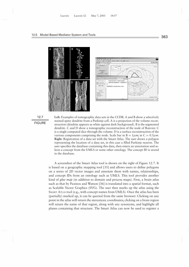
The CCDB mentioned earlier, in Example 12.3.1, houses different types of high-resolution, 3D light and electron microscopic reconstructions of cells and sub-cellular structures produced at the National Center for Microscopy and ImagingResearch19 [14]. It contains structural and protein distribution information de-rived from confocal, multiphoton, and electron microscopy, including correlatedmicroscopy. Many of the data sets are derived from electron tomography, a pow-erful technique for deriving 3D information from electron microscopic specimens.Electron tomography is similar in concept to medical imaging techniques like com-puterized axial tomography (CAT) scans and magnetic resonance imaging (MRI)in that it derives a 3D volume from a series of 2D projections through a structure.In this case, the structures are contained in sections prepared for electron mi-croscopy, which are tilted through a limited angular range. Examples of datasetsin the CCDB are shown on the left of Figure 12.7.
19.http://www.ncmir.ucsd.edu
Lacroix Lacroix-12 May 7, 2003 14:57
12.5 Model-Based Mediator System and Tools363
12.7
FIGURE
Left: Examples of tomographic data sets in the CCDB. A and B show a selectivelystained spiny dendrite from a Purkinje cell. A is a projection of the volume recon-struction (dendrite appears as white against dark background). B is the segmenteddendrite. C and D show a tomographic reconstruction of the node of Ranvier. Cis a single computed slice through the volume. D is a surface reconstruction of thevarious components comprising the node. Scale bar in B = 1µm; in C = 0.5µm.Right: Registration of a data set with the Smart Atlas. The user draws a polygonrepresenting the location of a data set, in this case a filled Purkinje neuron. Theuser specifies the database containing this data, then enters an annotation and se-lects a concept from the UMLS or some other ontology. The concept ID is storedin the database.
A screenshot of the Smart Atlas tool is shown on the right of Figure 12.7. Itis based on a geographic mapping tool [35] and allows users to define polygonson a series of 2D vector images and annotate them with names, relationships,and concept IDs from an ontology such as UMLS. This tool provides anotherkind of glue map (in addition to domain and process maps). First, a brain atlassuch as that by Paxinos and Watson [36] is translated into a spatial format, suchas Scalable Vector Graphics (SVG). The user then marks up the atlas using theSMART ATLAS tool (e.g., with concept names from UMLS). Once the atlas has been(partially) marked up, it can be queried from the same browser: Clicking on anypoint in the atlas will return the stereotaxic coordinates; clicking on a brain regionwill return the name of that region, along with any synonyms, and highlight allplanes containing that structure. The Smart Atlas can now be used to register a

Lacroix Lacroix-12 May 7, 2003 14:57
36412 A Model-Based Mediator System for Scientific Data Management
S
0
initial_input
15
forms(protein, synapse)
8
open(NMDA)
4
E-LTP
17
sustained_input
L-LTP
S
0
initial_input
1
{open(AMPA)}enters_Na[ion=sodium]{measure_of(depolarized_synapse,EPSP)}
2
binds_to(glutamate,NMDA)
8
{removed_magnesium}unplugs_NMDA
8
3
enters_Ca[ion=calcium]
9
opens(AMPA){open(AMPA)}
4
binds_to(Ca,CCal){active(CCal)} 5
activates(CCal,CaMKII){active(CaMKII)}
phosphorylates(AMPA){increased(sensitivity(AMPA))}
15
17
11
activates(CCal,adenylyl cyclase){active(adenylyl cyclase)}
12
creates_cAMP{active(cAMP)}
13
activates(cAMP,PKA){active(PKA)}
6
translocates(PKA,nucleus)
14
activates(PKA,MAPK){active(MAPK)}
phosphorylates(PKA, CREB){active(CREB)}
7
dimerizes(MAPK){dimerized(MAPK)}
16
translocates(dimerized(MAPK),nucleus)
phosphorylates(dimerized(MAPK),CREB){active(CREB)}
15
18
transcribes(CREB, gg:set(gene)){active(gg)}
19
synthesizes(g:member_of(gg), pp:set(protein))
S
forms(p:member_of(pp), synapse){more_synapses}
12.8
FIGURE
Process maps with elaborations and abstractions.
researcher’s data to a specific spatial location. This also links the registered dataautomatically to the UMLS ontology by virtue of the earlier semantic markupof spatial objects. To register source data, the user draws an arbitrary polygonrepresenting the approximate data location on one of the atlas planes (Figure 12.7,right). The user is then presented with a form that can be used to add annotationsor provide additional links to concepts of an ontology. Although the UMLS isused in the examples shown here, the user will eventually be able to use multipleontologies, including those of their own creation, for semantically indexing data.Tools are also being developed to define new terms and relationships in existingontologies. Another component of the system has been demonstrated and showshow spatial and conceptual information can be used together in a mediator system[37]; see also Martone et al.’s chapter in Neuroscience Databases [38] for furtherdetails on the use of the SMART Atlas.
12.6 RELATED WORK AND CONCLUSION
12.6.1 Related Work
Significant progress has been made in the general area of data mediation in recentyears, and several prototype mediator architectures have been designed by projectslike TSIMMIS [39], SIMS [40], Information Manifold [41], Garlic [42], and MIX[43]. While these approaches focus mostly on structural and schema aspects, theproblem of semantic mediation has also been addressed: In the DIKE system [44],

Lacroix Lacroix-12 May 7, 2003 14:57
12.6 Related Work and Conclusions365
the focus is on automatic extraction of mappings between semantically analogouselements from different schemas. A global schema is defined in terms of a con-ceptual model (SDR network), in which the nodes represent concepts and the (di-rected) edge labels represent their semantic distances, and a score called semanticrelevance measures the number of instances of the target node that are also in-stances of the source node. The correspondence between objects is defined interms of synonymies, homonymies, and sub-source similarities, defined by findingmaximal matching between the two graphs.
ODB-Tools [45] is a system developed on top of the MOMIS [46] systemfor modeling and reasoning about the common knowledge between two to-be-integrated schemas. They present the object-oriented language, ODLI3 , derivedfrom a description logic (OCDL). The language allows a user to create complexobjects with finite nesting of values, union and intersection types, integrity con-straints, and quantified paths. These constructs are used to define a class in oneschema as a generalization, aggregation, or equivalent with respect to another;subsumption of a class by another can be inferred. An integrated schema is ob-tained by clustering schema elements that are close to one another in terms of anaffinity metric.
Calvanese et al. [47] perform semantic information integration using an LAVapproach by expressing the conceptual schema by a description logic languagecalled DLR and subsequently defining non-recursive Datalog views to expresssource data elements in terms of the conceptual model. The language DLR rep-resents concepts, C, relations, R, and a set of assertions of the form C1 ⊂ C2
or R1 ⊂ R2, where R1, R2 are DLR relations with the same arity. Mediation isaccomplished by defining reconciliation correspondences, or specifications that aquery rewriter uses to match a conceptual-level term to data in different sources.
Recently Peim et al. [48] have proposed an extension to the well-knownTAMBIS system [49]. Their approach is similar to ours [18, 50] in that a logic-based ontology (in their case the ALCQI description logic) interfaces with anobject-wrapped source. While we use F-logic [28] as the internal knowledge rep-resentation and query language, their work focuses on how a query on the ontologyis transformed to monoid comprehensions for semantic query optimization.
12.6.2 Summary: Model-Based Mediationand Reason-Able Meta-Data
MBM was presented as a methodology that supports information integration ofscientific data across complex, multiple-world scenarios as found in the neuro-science domain. In this framework, object-oriented models and conceptual mod-els (CM), domain maps (DM), and process maps (PM) all provide means tocapture more domain semantics and thus can act as glue knowledge sources to link
Unknown

Lacroix Lacroix-12 May 7, 2003 14:57
36612 A Model-Based Mediator System for Scientific Data Management
hard-to-correlate sources. Mechanisms to contextualize source data formally werepresented. The graph structures thus constructed have been shown to be useful fornavigating across related concepts and querying local data during navigation [29].
Logic formalizations of DMs and PMs can be seen as “reason-able” or “ex-ecutable” “meta-data” (see a paper by Horrocks [51]): Unlike conventional, de-scriptive meta-data, which are primarily used for data discovery, formal ontologies,such as DMs and PMs, can support much more versatile computational tasks ina mediator system, as illustrated in this chapter. For example, different and ap-parently unrelated data objects can be associated and retrieved together or evenfused by the mediator’s integrated view definition (IVD), because IVDs can bedefined as deductive rules over DMs and PMs (Figure 12.3). In this way, in model-based mediation (MBM), logic rules play the role of executable or computationalmeta-data for scientific data integration. The latter is a challenging applicationand benchmark for combined database and knowledge representation techniques.
ACKNOWLEDGMENTS
This work has been supported by NIH/NCRR 3 P41 RR08605-08S1 (BiomedicalInformatics Research Network [BIRN]) and NSF-NPACI Neurosciences ThrustACI 9619020. The authors thank their colleagues and students involved in theBIRN project for their contributions, in particular, Xufei Qian, Edward Ross,Joshua Tran, and Ilya Zaslavsky.
REFERENCES
[1] Y. Papakonstantinou, A. Gupta, and L. M. Haas. “Capabilities-Based QueryRewriting in Mediator Systems.” Distributed and Parallel Databases 6, no. 1(1998): 73–110.
[2] C. Li, R. Yerneni, V. Vassalos, et al. “Capability Based Mediation in TSIMMIS.” InProceedings of the ACM International Conference on Management of Data(SIGMOD), 564–566. 1998.
[3] National Partnership for Computational Infrastructure (NPACI): NeuroscienceThrust Area, 2001. http://www.npaci.edu/Thrusts/Neuro/.
[4] Biomedical Informatics Research Network Coordinating Center (BIRN-CC).University of California, San Diego. http://nbirn.net/, 2001.
[5] V. Kashyap and A. Sheth. “Semantic and Schematic Similarities Between DatabaseObjects: A Context-Based Approach.” VLDB Journal 5, no. 4 (1996): 276–304.

Lacroix Lacroix-12 May 7, 2003 14:57
References367
[6] D. Calvanese, G. D. Giacomo, M. Lenzerini, et al. “Description Logic Frameworkfor Information Integration.” In Proceedings of the Sixth International Conferenceon Principles of Knowledge Representation and Reasoning (KR’98), 2–13. MorganKaufmann, 1998.
[7] O. Bozdagi, W. Shan, H. Tanaka, et al. “Increasing Numbers of Synaptic PunctaDuring Late-Phase LTP: N-Cadherin is Synthesized, Recruited to Synaptic Sites,and Required for Potentiation.” Neuron 28, no. 1 (2000): 245–259.
[8] J. Kasahara, K. Fukunaga, and E. Miyamoto. “Activation of Calcium/Calmodulin-Dependent Protein Kinase IV in Long Term Potentiation in the RatHippocampal CA1 Region.” Journal of Biological Chemistry 276, no. 26 (2001):24044–24050.
[9] A. Gupta, B. Ludascher, and M. E. Martone. “An Extensible Model-BasedMediator System with Domain Maps.” In Demonstration Session of the 21stInternational Conference on Data Engineering (ICDE), Heidelberg, Germany,2001.
[10] S. Chakravarthy, J. Grant, and J. Minker. “Logic-Based Approach to SemanticQuery Optimization.” ACM Transactions on Database Systems (TODS) 15, no. 2(1990): 162–207.
[11] B. Ludascher, Y. Papakonstantinou, and P. Velikhov. “Navigation-DrivenEvaluation of Virtual Mediated Views.” In Proceedings of the InternationalConference on Extending Database Technology (EDBT), Lecture Notes inComputer Science 1777, 150–165. xxxxx: Springer, 2000.
[12] Y. Papakonstantinou and V. Vassalos. “The Enosys Markets Data IntegrationPlatform: Lessons from the Trenches.” In International Conference on Informationand Knowledge Management (CIKM), 2001.
[13] A. Gupta, B. Ludascher, and M. E. Martone. “Registering Scientific InformationSources for Semantic Mediation.” In 21st International Conference on ConceptualModeling (ER). Lecture Notes in Computer Science 2503. Springer, 2002.
[14] M. E. Martone, A. Gupta, M. Wong, et al. “A Cell-Centered Database for ElectronTomographic Data.” Journal of Structural Biology 138 (2002): 145–155.http://ncmir.ucsd.edu/CCDB/.
[15] A. Artale, E. Franconi, N. Guarino, et al. “Part-Whole Relations inObject-Centered Systems: An Overview.” Data and Knowledge Engineering 20,(1996): 347–383.
[16] P. Mitra, G. Wiederhold, and M. L. Kersten. “A Graph-Oriented Model forArticulation of Ontology Interdependencies.” In Proceedings of the InternationalConference on Extending Database Technology (EDBT), 86–100. 2000.
[17] I. R. Horrocks. “Using an Expressive Description Logic: FaCT or Fiction?” InKR’98: Principles of Knowledge Representation and Reasoning, edited by A. G.Cohn, L. Schubert, and S. C. Shapiro, 636–645. San Francisco: MorganKaufmann, 1998.

Lacroix Lacroix-12 May 7, 2003 14:57
36812 A Model-Based Mediator System for Scientific Data Management
[18] B. Ludascher, A. Gupta, and M. E. Martone. “Model-Based Mediation withDomain Maps.” In Proceedings of the 17th International Conference on DataEngineering (ICDE). New York: IEEE Computer Society, 2001.
[19] D. Calvanese, G. D. Giacomo, M. Lenzerini, et al. “Description Logic Frameworkfor Information Integration.” In Principles of Knowledge Representation andReasoning, 2–13. s1998.
[20] B. Ludascher, A. Gupta, and M. E. Martone. “Model-Based Mediation withDomain Maps.” In Proceedings of the 17th International Conference on DataEngineering (ICDE). New York: IEEE Computer Society, 2001.
[21] M. Kifer, G. Lausen, and J. Wu. “Logical Foundations of Object-Oriented andFrame-Based Languages.” Journal of the ACM 42, no. 4 (July 1995): 741–843.
[22] FLORA homepage. http://www.cs.sunysb.edu/∼sbprolog/flora/.
[23] FLORID homepage. http://www.informatik.uni-freiberg.de/∼dbis/florid/.
[24] B. Ludascher, A. Gupta, and M. E. Martone. “Model-Based InformationIntegration in a Neuroscience Mediator System.” In Proceedings of the 26thInternational Conference on Very Large Data Bases (VLDB), 639–642. SanFrancisco: Morgan Kaufmann, 2000.
[25] R. Himmeroder, G. Lausen, B. Ludascher, et al. “FLORID: A DOOD-System forQuerying the Web.” In Demonstration Session at EDBT. Valencia, Spain,1998.
[26] B. Ludascher, R. Himmeroder, G. Lausen, et al. “Managing Semistructured Datawith FLORID: A Deductive Object-Oriented Perspective.” Information Systems23, no. 8 (1998): 589–613.
[27] G. Lausen, B. Ludascher, and W. May. “On Active Deductive Databases: TheStatelog Approach.” In Transactions and Change in Logic Databases, LectureNotes in Computer Science 1472, edited by B. Freitag, H. Decker, M, Kifer, et al.Springer, 1998.
[28] M. Kifer, G. Lausen, and J. Wu. “Logical Foundations of Object-Oriented andFrame-Based Languages.” Journal of the ACM 42, no. 4 (July 1995): 741–843.
[29] X. Qian, B. Ludascher, M. E. Martone, et al. “Navigating Virtual InformationSources with Know-ME.” In EDBT, Lecture Notes in Computer Science 2287,2002.
[30] B. Ludascher, A. Gupta, and M. E. Martone. “Model-Based InformationIntegration in a Neuroscience Mediator System.” In Proceedings of the 26thInternational Conference on Very Large Data Bases (VLDB), 639–642. SanFrancisco: Morgan Kaufmann, 2000.
[31] G. Yang and M. Kifer. “FLORA: Implementing an Efficient DOOD System Using aTabling Logic Engine.” In Sixth International Conference on Rules and Objects inDatabases (DOOD), 2002.

Lacroix Lacroix-12 May 7, 2003 14:57
References369
[32] C. Draxler. A Powerful Prolog to SQL Compiler, technical report. Munchen,Germany: Centre for Information and Language Processing, Ludwigs-Maximillians-Universitat Munchen, 1992.
[33] B. Ludascher. “Mediator Query Processing with Prolog Technology,” technicalnote, BIRN-DI-TN-2002-01. Biomedical Informatics Research Network, 2002.
[34] K. F. Sagonas, T. Swift, and D. S. Warren. “XSB as an Efficient Deductive DatabaseEngine.” In Proceedings of the ACM International Conference on Management ofData (SIGMOD), 442–453. xxx: xxxx, 1994.
[35] I. Zaslavsky. “A New Technology for Interactive Online Mapping.” CartographicPerspectives 37 (2000): 65–77.
[36] G. Paxinos and C. Watson. The Rat Brain in Stereotaxic Coordinates. San Diego:Academic Press, 1998.
[37] A. Gupta, B. Ludascher, M. E. Martone, et al. “A System for Managing AlternateModels in Model-Based Mediation.” In Advances in Databases, 19th BritishNational Conference on Databases (BNCOD 19), Lecture notes in ComputerScience 2405. Xxx: Springer, 2002.
[38] M. E. Martone, A. Gupta, B. Ludascher, et al. “Federation of Brain Data throughKnowledge-Guided Mediation.” In Neuroscience Databases: A Practical Guide,edited by R. Kotter, 275–292. Boston: Kluwer Academic Publishers, 2002.
[39] H. Garcia-Molina, Y. Papakonstantinou, D. Quass, et al. “The TSIMMISApproach to Mediation: Data Models and Languages” (Extended Abstract). InNext Generation Information Technologies and Systems. 1995.
[40] C. A. Knoblock, S. Minton, J. L. Ambite, et al. “Modeling Web Sources forInformation Integration.” In Proceedings of the Fifteenth National Conference onArtificial Intelligence. 1998.
[41] A. Y. Levy, A. Rajaraman, and J. J. Ordille. “Querying Heterogeneous InformationSources Using Source Descriptions.” In Proceedings of the InternationalConference on Very Large Data Bases (VLDB), 251–262. 1996.
[42] L. M. Haas, D. Kossmann, E. L. Wimmers, et al. “Optimizing Queries AcrossDiverse Data Sources.” In Proceedings of the International Conference on VeryLarge Data Bases (VLDB), 276–285. 1997.
[43] C. Baru, A. Gupta, B. Ludascher, et al. “XML-Based Information Mediation withMIX.” In Proceedings of the ACM SIGMOD International Conference onManagement of Data (SIGMOD 1999), 597–599. Philadelphia: ACM Press,1999.
[44] L. Palopoli, G. Terracina, and D. Ursino. “The System DIKE: Towards theSemi-Automatic Synthesis of Cooperative Information Systems and DataWarehouses.” In Proceedings of the ADBIS-DASFAA Symposium, 108–117.2000.

Lacroix Lacroix-12 May 7, 2003 14:57
37012 A Model-Based Mediator System for Scientific Data Management
[45] D. Beneventano and S. Bergamaschi. “Extensional Knowledge for Semantic QueryOptimization in a Mediator-Based System.” In International Workshop onFoundations of Models for Information Integration (FMII-2001), 2001.
[46] S. Bergamaschi, S. Castano, and M. Vincini. “Semantic Integration ofSemistructured and Structured Data Sources.” SIGMOD Record 28, no. 1 (1999):54–59.
[47] D. Calvanese, S. Castano, F. Guerra, et al. “Towards a ComprehensiveMethodological Framework for Semantic Integration of Heterogeneous DataSources.” In Eighth International Workshop on Knowledge Representation MeetsDatabases (KRDB), 2001.
[48] M. Peim, E. Franconi, N. Paton, et al. “Query Processing with Description LogicOntologies Over Object-Wrapped Databases.” In Proceedings of the InternationalConference on Scientific and Statistical Database Management (SSDBM). 2002.
[49] C. Goble, R. Stevens, G. Ng, et al. “Transparent Access to Multiple BioinformaticsInformation Sources.” IBM Systems Journal 40, no. 2 (2001): 534–551.
[50] A. Gupta, B. Ludascher, and M. E. Martone. “Knowledge-Based Integration ofNeuroscience Data Sources.” In Proceedings of the Twelfth InternationalConference on Scientific and Statistical Database Management (SSDBM), 39–52.IEEE Computer Society, 2000.
[51] I. Horrocks. “DAML+OIL: A Reason-Able Web Ontology Language.” InProceedings of the International Conference on Extending Database Technology(EDBT), 2–13. 2002.