Programma esame Fondamenti di Elettrotecnica (PRIMA PARTE) Prof : Antonio Luchetta.
date post
20-Dec-2015Category
view
217download
3
A. Luchetta 17th Real-Time Conference, 25 May 2010, Lisboa, Portugal. 1/12
Data Acquisition in the ITER Ion Source ExperimentData Acquisition in the ITER Ion Source ExperimentAdriano Luchetta, Gabriele Manduchi, Antonio Barbalace, Anton Soppelsa, Cesare Taliercio
Consorzio RFX – Euratom-ENEA Association, Padova, [email protected]
SummarySummary
Introduction
Requirements
Software frameworks
EPICS/MDSplus integration
Real-time performance
Conclusions
CAD view of SPIDER Vessel

A. Luchetta 17th Real-Time Conference, 25 May 2010, Lisboa, Portugal. 2/12
Introduction (1) - Context
Tokamaks require additional heating to reach fusion-relevant parameters, as ohmic heating is limited by instability at a given toroidal magnetic field value.
Additional heating adds controllability:Plasma rotation, current profile controlMHD instability control
Additional heating is provided by: Radio Frequency coupled to plasma
(ion and electron cyclotron, lower hybrid)
Heating HHeating H00/D/D00 Neutral Beams Neutral Beams (HNB) injected into plasma neutral to reach plasma core without magnetic deflection
ITER will have #2 HNBs Injectors with option for 3.
Fig.1. JET toroidal chamber.

A. Luchetta 17th Real-Time Conference, 25 May 2010, Lisboa, Portugal. 3/12
Fig.2. CAD view of ITER HNB.
Introduction (2) - Neutral Beam Test Facility
Required parameters for ITER HNBs are well beyond achievements in devices developed so far.
To develop full-size HNB and test it up to maximum performance, ITER approved construction of ad-hoc Neutral Beam Test FacilityNeutral Beam Test Facility
H° D°
Beam Energy 1MeV 1MeV
Beam Power 16.5MW 16.5MW
Beam-on time 3600s 3600s
Table I. Main parameters of ITER HNB.
It is under construction in Padova, Italy, and will comprise 2 test-beds Full-size Ion Source – op. 2013Full-size Ion Source – op. 2013
Called SPIDERCalled SPIDER
Full-size HNB ITER CODAC compatible
A. Luchetta 17th Real-Time Conference, 25 May 2010, Lisboa, Portugal. 4/12
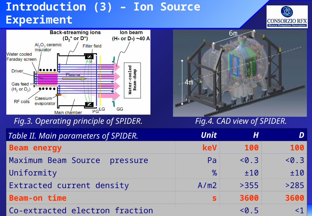
Introduction (3) – Ion Source Experiment
Fig.3. Operating principle of SPIDER. Fig.4. CAD view of SPIDER.
6m
4m
Wat
er-c
oo
led
Bea
m-d
um
p Unit H D
Beam energy keV 100 100
Maximum Beam Source pressure Pa <0.3 <0.3
Uniformity % ±10 ±10
Extracted current density A/m2 >355 >285
Beam-on time s 3600 3600
Co-extracted electron fraction (e-/H- or e-/D-) <0.5 <1
Table II. Main parameters of SPIDER.

A. Luchetta 17th Real-Time Conference, 25 May 2010, Lisboa, Portugal. 5/12
Data Acquisition Requirements (1)SPIDER Diagnostics
Description Measurement(s)
Thermocouples Temperature
Electric Measurements Voltage, current, power
Calorimetry Coolant flow, temperature, pressure, thermal power
Electrostatic Probes Electron temperature and density
Source Spectroscopy Source plasma parameters
Beam Tomography Beam position, shape, uniformity
Beam Spectroscopy Beam uniformity, beam divergence, stripping losses
Cavity Ring Down Spectr. Ion source H- density
Neutron/X Ray Diagnostics Neutron flux and X-Ray
Instrumented CalorimeterInstrumented Calorimeter Beam uniformity and divergence (limited up to 10s)Beam uniformity and divergence (limited up to 10s)
Diagnostics Imaging Visible beam images and beam dump temperature
Table III. SPIDER Diagnostics Systems.

A. Luchetta 17th Real-Time Conference, 25 May 2010, Lisboa, Portugal. 6/12
Data Acquisition Requirements (2) - Quantity
Day (25% duty) cycle)
GB 692Week (4 days) TB 2.77
Year (40 weeks) TB 110.79
Period Unit Data
Table V. Estimated data amount.
Table IV. Channel number and estimated data throughput.
Data Class Sampling rate
Chan.No.
Unit Throughput Beam dump
ThroughputInstr. Calor.
PLC-based ≤ 20 S/s 136 kB/s 2.02 2.02
Continuous ≤ 20 kS/s 649 MB/s 3.11 3.23
Event-driven ≤ 10 MS/s 74 MB/s 1.14 1.14
Burst ≤ 100 MS/s 1 MB/s 3.00 3.00
Diagn. Images ≤ 150 fps 76 MB/s 88.93 121.07
TOTAL 936 MB/s 96.18 129.07

A. Luchetta 17th Real-Time Conference, 25 May 2010, Lisboa, Portugal. 7/12
Software Frameworks (1)
Control & data acquisition will be implemented by open source, collaborative software frameworks: EPICSEPICS for control (ITER-driven)(ITER-driven) MDSplusMDSplus for data acquisition
MDSplus is a set of data management tools: Data acquisition system (hardware configuration, data read-out)
Remote data access system
Data visualization and analysis system
data available via FORTRAN, C, C++, Java, idl, matlab, visual basic, labview, php, pythondata available via a unified object model in python, java, c++, matlab
Data archival system based on a shared record store (pulse file)
Hierarchical; Simple APIDoes not distinguish between classes of data (python-like)

A. Luchetta 17th Real-Time Conference, 25 May 2010, Lisboa, Portugal. 8/12
Software Frameworks (2) - MDSplus
There have been over 8000 downloads of MDSplus installation kits
Sites using complete MDSplus system: TCV (EPFL - Switzerland), RFX (Euratom/ENEA - Italy),RFX (Euratom/ENEA - Italy), Heliac (ANU - Australia),MST (U.
Wisconsin), HIT, TIP, TCS and ZAP (U. Washington), PISCES (UCSD), CHS (NIFS - Japan), LDX (MIT), HBT-IP and CTX (Columbia U.), Alcator C-Mod (MIT)
NSTX (PPPL) and KSTAR (NFRI - S. Korea) use MDSplus and EPICSNSTX (PPPL) and KSTAR (NFRI - S. Korea) use MDSplus and EPICS..
Sites using MDSplus remote data access: JET, ASDEX-Upgrade, Tore Supra, DIIID
Physics codes EFIT, TRANSP, GS2
Integrated Tokamak Modeling Task (EFDA)
ITPA collaborative data archivesFig.5. MDSplus sites.

A. Luchetta 17th Real-Time Conference, 25 May 2010, Lisboa, Portugal. 9/12
EPICS/MDSplus integration (1)
We want a high level of integration between EPICS and MDSplus. New MDSplus-based EPICS Channel ArchiverEPICS Channel Archiver (JCA-based).
Data Access Time
0
50
100
150
200
250
300
350
400
500 1000 1500 2000 2500 3000 3500 4000
N. of samplesAc
cess
tim
e (m
s)
'RPC XML'
mdsip
See G. ManduchiPoster PCM-16Poster PCM-16
Fig. 6. Remote data access timeto EPICS and MDSplus archivers.
Table 6. Percentage of lost samples inEPICS Channel Archiver.
Number of PVsCALC - 10 Hz Lost Samples %
2000 0.0374000 7.66000 358000 45
10000 54
2.4 GHz quad-core Linux workstation 4 GB RAM and SATA disk controller

A. Luchetta 17th Real-Time Conference, 25 May 2010, Lisboa, Portugal. 10/12
EPICS/MDSplus integration (2)New EPICS Records mdsput provides direct storage of EPICS IOC
data into MDSplus-based Channel Archiver.
mdsaction allows to command ‘Mdsplus Mdsplus actionsactions’ by an EPICS IOC.
MDSplus actionsMDSplus actions execute operations.
INIT methodINIT method: reads set-up information from pulsefile and configures hardware.
STORE methodSTORE method: reads samples from ADC and stores them into pulse file.
mdsevent implements reception of ‘MDSplus events’ (asynchronous communication).
MDSplus events can also carry data.
Channel Access Server for MDSPlusChannel Access Server for MDSPlus
PV
mdsactionmdsaction INIT
ST
OR
E
mdseventmdsevent(UDP)(UDP)
Channel Archiver (CAC)Channel Archiver (CAC)Channel Archiver (CAC)Channel Archiver (CAC)
Ch. Access
mdsip (TCP)
Fig. 7. EPICS and MDSplus data flow.
ADCADCADCADC
MDSplusMDSplusMDSplusMDSplus
CASCASCASCAS
MDSplus Pulse FileMDSplus Pulse FileMDSplus Pulse FileMDSplus Pulse File
mdsputmdsput
EPICS IOCEPICS IOCEPICS IOCEPICS IOCwavewave

A. Luchetta 17th Real-Time Conference, 25 May 2010, Lisboa, Portugal. 11/12
Real-time Performance (1)
Measurements on real-time (RT) performance of EPICS and the latency ‘fingerprint’ of Linux k.2.6 and RT patches (tollerable latency: a few hundreds s).
Fig. 8. Measured latency values.
Reference applicationMARTeEPICS
Reference application +EPICS XMARTe *
test 1 kHz
Latency (s)
Occurrence graphbin width 0.1 s
Fig. 9. Sample application.
Performance See A. BarbalacePoster PFE-13Poster PFE-13
MARTe See A.C. NetoPoster PFE-4Poster PFE-4
NI6255x86 Intel Core 2 Duo 2.66GHz
3MB cache and 3GB RAMLinux 2.6.29.6 rt-24

A. Luchetta 17th Real-Time Conference, 25 May 2010, Lisboa, Portugal. 12/12
Conclusions
Requirements of SPIDER data acquisition are not trivial due to the long duration of the SPIDER beam-on time, the large data amount and, finally, the real-time constraints.
System software architecture will rely on the integration of EPICS and MDSplus, for which specific tools have been implemented and profiled, such as the MDSplus Channel Archiver, interface EPICS records and, in progress, the MDSplus Channel Access Server.
The real-time characteristics of EPICS and Linux kernel 2.6 with real-time patches satisfy the real-time requirements of the SPIDER data acquisition and fast real-time control.
Thank you for your attention.Thank you for your attention.