11/01/05Wave Energy Power Generator2 Presentation Agenda Proposal Feedback –Project Scope...
32
-
date post
21-Dec-2015 -
Category
Documents
-
view
214 -
download
0
Transcript of 11/01/05Wave Energy Power Generator2 Presentation Agenda Proposal Feedback –Project Scope...


11/01/05 Wave Energy Power Generator 2
Presentation Agenda• Proposal Feedback
– Project Scope– Target Values
• Concept Evaluation– Concept Screening / Scoring– Design Selection
• Technical Approach– Wave Data Statistics– Mathematical Model & Simulation– Product Architecture / Geometric Layout
• Subsystems– Cable / Reel– Mechanical Rectifier / Gearbox– Generator / Alternator
• Project Budget• Conclusion

11/01/05 Wave Energy Power Generator 3
Project Scope/Objective• Project Focus: Device that harnesses wave
energy to generate electrical power on a buoy– Off-shore location requires buoy to be self-sustaining
– Power output in the 100’s of Watts range
• Power will be stored in batteries to be drawn from when needed
• Benefits of wave over solar– Higher Energy Densities
– Availability / Reliability

11/01/05 Wave Energy Power Generator 4
Target ValuesMetric
No.Need Nos.
Metric UnitsMarginal
ValueIdeal
Value
1 1 Power output per cost of unit Watts / $ >.25 >.5
2 2 Power Output Watts > 100 >300
3 3,4 Working Period Months >6 >12
4 3,4,6 Number of moving components Number <6 <4
5 5 Maximum height of wave allowed Feet >2 >6
6 6,8 Number of components Number <8 <5
7 7 Cost of Repair at catastrophic failure Dollars <500 <100
8 6,8 Weight Pounds <200 100
9 8 Size Volume (ft3) <15 <8

11/01/05 Wave Energy Power Generator 5
Concept Screening1a 1b 2 3 4a 4b 5
NeedCost EffectivenessPower OutputMaintenanceReliability / RobustnessMaximum Wave ConditionsAssembly TimeCost of FailureTransportability
Sum +Sum 0Sum -
Net ScoreRank
Selection Criteria
Reference
Concepts
Relative Performance Rating
Worse than Reference -
Equal to Reference 0
Better than Reference +
11/01/05 Wave Energy Power Generator 6
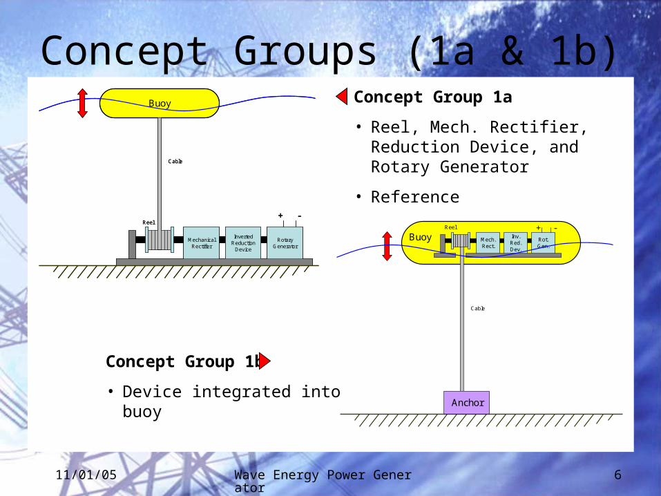
Concept Groups (1a & 1b)Buoy
Rotary Generator
Inverted Reduction
Device
Mechanical Rectifier
Reel+ -
Cable
Buoy
Rotary Generator
Inverted Reduction
Device
Mechanical Rectifier
Reel+ -
Cable
Cable
Anchor
Rot. Gen.
Inv. Red. Dev.
Mech. Rect.
Reel + -Buoy
Concept Group 1a
• Reel, Mech. Rectifier, Reduction Device, and Rotary Generator
• Reference
Concept Group 1b
• Device integrated into buoy

11/01/05 Wave Energy Power Generator 7
Concept Screening
1a 1b 2 3 4a 4b 5
NeedCost Effectiveness 0 +Power Output 0 0Maintenance 0 +Reliability / Robustness 0 +Maximum Wave Conditions 0 0Assembly Time 0 +Cost of Failure 0 -Transportability 0 0
Sum + 0 4Sum 0 8 3Sum - 0 1
Net Score 0 3Rank
Selection Criteria
Reference
Concepts

11/01/05 Wave Energy Power Generator 8
Concept Groups (2 & 3)Buoy
Crank
Rotary Generator
Inverted Reduction
Device
+ -Crank Arm
Guide
Side View
Buoy
Permanent Magnet Direct Drive Linear Generator
Anchor
Concept Group 2
• Crank, Reduction Device, and Rotary Generator
Concept Group 3
• Piston and Direct Drive Linear Generator

11/01/05 Wave Energy Power Generator 9
Concept Screening
1a 1b 2 3 4a 4b 5
NeedCost Effectiveness 0 + + -Power Output 0 0 - +Maintenance 0 + 0 +Reliability / Robustness 0 + 0 +Maximum Wave Conditions 0 0 - -Assembly Time 0 + 0 -Cost of Failure 0 - - -Transportability 0 0 0 0
Sum + 0 4 1 3Sum 0 8 3 4 1Sum - 0 1 3 4
Net Score 0 3 -2 -1Rank
Selection Criteria
Reference
Concepts

11/01/05 Wave Energy Power Generator 10
Concept Groups (4 & 5)Buoy
TurbineConnected to Rotary Generator
Anchor
Check valves
Piston
Anchor
Buoy
Turbine with Rotary Generator
Concept Group 4a&b
• Piston, Fluid, System of Valves, Turbine, and Rotary Generator
• 4a – Closed Turbine
• 4b – Open Turbine
Concept Group 5
• Air Camber, Oscillating Air, Turbine, and Rotary Generator

11/01/05 Wave Energy Power Generator 11
Concept Screening
1a 1b 2 3 4a 4b 5
NeedCost Effectiveness 0 + + - - - 0Power Output 0 0 - + 0 0 -Maintenance 0 + 0 + 0 - +Reliability / Robustness 0 + 0 + - - +Maximum Wave Conditions 0 0 - - - - -Assembly Time 0 + 0 - 0 0 +Cost of Failure 0 - - - - - -Transportability 0 0 0 0 0 0 0
Sum + 0 4 1 3 0 0 3Sum 0 8 3 4 1 4 3 2Sum - 0 1 3 4 4 5 3
Net Score 0 3 -2 -1 -4 -5 0Rank 2 1 5 4 6 7 2
Continue? Yes Yes No Yes No No Yes
Selection Criteria
Reference
Concepts

11/01/05 Wave Energy Power Generator 12
Concept Scoring
Relative Performance Rating
Much Worse than Reference 1
Worse than Reference 2
Equal to Reference 3
Better than Reference 4
Much better than Reference 5
Need Weight
Rating Weighted Score
Rating Weighted Score
Rating Weighted Score
Rating Weighted Score
Cost Effectiveness 0.3758 3 1.1274 4 1.5032 1 0.3758 3 1.1274Power Output 0.2695 3 0.8085 3 0.8085 5 1.3475 2 0.539Maintenance 0.1277 3 0.3831 5 0.6385 4 0.5108 4 0.5108Reliability / Robustness 0.1064 3 0.3192 4 0.4256 5 0.532 4 0.4256Maximum Wave Conditions 0.0496 3 0.1488 3 0.1488 2 0.0992 2 0.0992Assembly Time 0.0355 3 0.1065 4 0.142 1 0.0355 4 0.142Cost of Failure 0.0213 3 0.0639 1 0.0213 1 0.0213 1 0.0213Transportability 0.0142 3 0.0426 3 0.0426 3 0.0426 3 0.0426
Total Score (normalized)
RankContinue?
0.969
4No
5
No
1.000 1.244 0.988
2 1 3No Yes
Selection Criteria 31a 1bReference
Concepts

11/01/05 Wave Energy Power Generator 13
Final Design Selection
• Spring-Reel Buoy Design
• Scored best in top 3 needs– Cost Effectiveness– Power Output– Maintenance
Cable
Anchor
Rot. Gen.
Inv. Red. Dev.
Mech. Rect.
Reel + -Buoy

11/01/05 Wave Energy Power Generator 14
Two Possible Design Location: 1. Hudson River2. Raritan Bay (Coney Island)
Wave Data Analysis
1
2

11/01/05 Wave Energy Power Generator 15
Wave Heights Over A Period of 8 days
Period (seconds)
Wave Heights (inches)
Hudson River Data
Histogram of Wave Periods During Typical Hours
Period (seconds)
Frequency (No of Wave Occurrence)
• Mean height is about 6 inches• Maximum is around 20 inches• Minimum is around 1 inch• Mostly ferry-generated waves
•Mean Period is about 2~3 sec•Maximum, 10 sec•Minimum, 1 sec•Majority of data falls between
1~6 seconds
Wave Height
Wave Period

11/01/05 Wave Energy Power Generator 16
Coney Island, Raritan Bay:Histogram of Significant Wave Heights
0
2000
4000
6000
8000
Wave Height (inches)
Freq
uenc
y
Coney Island, Raritan Bay:Histogram of Significant Wave Periods
0
1000
2000
3000
4000
5000
Wave Period (seconds)
Fre
qu
ency
Raritan Bay DataWave Height
Wave Period
• Hs = 4.0 * sqrt(m0)• Mean Height, 12.2 inches• Maximum, 81.5 inches• Minimum, 1.1 inches• 95% C.L.: 3.94~27.95• 99% C.L.: 2.76~43.30
• Period of the significant waves.• Mean Period, 7.14 sec• Maximum, 19 sec• Minimum, 2.6 sec• 95% C.L.: 3.1~12.8• 99% C.L.: 2.9~14.2

11/01/05 Wave Energy Power Generator 17
Mathematical Model & Simulation
• Three major design segments relate to several system models• Capturing / following wave motion model developed• In the process of developing mechanical system & electrical system models
Linear to rotary
oscillation
Oscillatory to Unidirectional
Flywheel & Inverted Reduction
Wave
Line
ar O
scill
atio
n
Rot
ary
Osc
illat
ion
Uni
dire
ctio
nal R
otat
ion
Unc
ondi
tione
d E
lect
rical
Pow
er
Hig
her
Spe
ed R
otat
ion
Electrical Conditioning
Con
ditio
ned
Ele
ctric
al P
ower
Motion Capturing
Device
Wave Motion
Mechanical Motion
Mechanical Motion
Electrical Energy
Generator/Alternator
Capture the wave motion
Electricity Generating
DeviceMotion Conversion Device(s)
Flow Chart of Wave Energy Generator
System Model for Simulation
0
1
2
3
4
5
6
7
0 1 2 3 4 5 6 7-8
-6
-4
-2
0
2
4
6
8
0 1 2 3 4 5 6 7
0
1
2
3
4
5
6
7
0 1 2 3 4 5 6 7
)sin( tyw

11/01/05 Wave Energy Power Generator 18
Assumptions:1. Wavelengths of waves are larger than buoy diameter2. Spring coefficient is constant3. Cable always remains tight4. Generating force is a quadratic function of speed. 5. Damping/drag force similar to an object moving in a
fluid.
yw y’w y’’w
yb y’b y’’b
Fb
W
FgenFspr
Arbitrary reference for yw and yb
FdragAbuoy
Water Line
Wave Motion Model
Force of Buoyancy, Fb
gAyygVF OHbuoybwOHsubb 22 )(
Force of Spring, Fspr.
)( preloadbpreloadbspr yykFkyF
Force from Generator, Fgen
cybyaF bbgen ')'( 2
gengen TF ,
RPMyb ,'
"bdragsprgenb yg
WFFFWF
2)''(2
1bwbuoywaterdragdrag yyACF
Damping/Drag Force, Fdrag0
Governing Equations

11/01/05 Wave Energy Power Generator 19
Wave Motion Simulation
• Compare Sinusoidal wave input to buoy displacement output
• Model Showed• Overall weight had little effect• Radius of device & reel spring
constant had a greater affect on output
time, sec
Wa
ve
he
igh
t, i
nc
he
s
time, sec
Bu
oy
dis
pla
ce
me
nt,
in
ch
es

11/01/05 Wave Energy Power Generator 20
PRODUCT ARCHITECTURE
ControlReel
Control Mechanism
Reel
Convert linear motion into two way rotational motionEnclose
Device
Waterproof Device
Casing
Chassis
Provide Structural Support
Hold Device
Store Batteries
Harness wave Energy
Buoy
Rectifier
Rectify Motion into unidirectional rotation
Flow of Force
Flow of signal or Data
Flow of Energy
Gear Box
Speed up rotation of shaft
Rotary Generator
Convert Kinetic Energy into Electrical Energy
Charge Batteries
Anchored cable
Secure buoy position

11/01/05 Wave Energy Power Generator 21
GEOMETRIC LAYOUT
Anchor
Casing
Cable
Buoy
Gear Box
Rectifier
Batteries
Reel
Rotary Generator

11/01/05 Wave Energy Power Generator 22
INCIDENTAL INTERACTIONCasing
Chassis
Buoy
RectifierReel
Gear Box Rotary Generator
Anchored cableVibration Vibration, coupling
Thermal ExpansionVibration, shaft
Vibration, coupling
Styling
Friction
Sealing
Control
Torque, RPM
Torque, RPM
Torque, RPM

11/01/05 Wave Energy Power Generator 23
System Integration: Requirements
Functional Requirements:
1. The device shall charge 12V batteries.
2. The device shall be able to withstand 1 meter waves.
3. The device shall be able to produce at least 100 Watts at average wave conditions.
Non-functional Requirements:
1. The total weight of the device shall be under 200 lbs.
2. The center of gravity shall be at the center of the buoy.
Technical Performance Metrics:
1. Total efficiency of the device (%)
2. Total weight of the device (lbs)
3. The location of center of gravity from bottom center of buoy (inches)
4. Total number of moving parts (number)

11/01/05 Wave Energy Power Generator 24
Reel Design Considerations• The length of maximum cable
payout will be determined by site conditions.
• The spring must be strong enough for high waves, but not too strong to kill the small waves.
• An oscillating guide may be used to line the cable up.
Reel with a guide even out the cable
Reel Diameter
Large
Less sensitive to radius change
Larger inertia
More need for gearing up
Small
Sensitive to radius change
Less inertia
Less need for gearing up
vs.

11/01/05 Wave Energy Power Generator 25
What it Does How It Works
Unidirectional Clutch Bearings
Simple gearing mechanism utilizing one-way clutch bearings
Mechanical Rectifier Design
Input
Output
Engages w/ input of CCW
Engages w/ input of CW

11/01/05 Wave Energy Power Generator 26
Mechanical Rectifier CAD ModelIsometric View
Exploded Top View

11/01/05 Wave Energy Power Generator 27
Gearbox Concepts & ConsiderationsPlanetary Gearing
• Compact, highly efficient and reliable
Parallel Shaft Gearing• Low part count
Worm Gears• High ratio, compact, very low efficiency
Belt• Inexpensive, low reliability
Optimal gear ratio dependent on generator RPM range
Need for a Flywheel:• Will allow generator to remain around the operational
range where the efficiency is maximum.

11/01/05 Wave Energy Power Generator 28
Generator/AlternatorMajor Concerns:
• Operate at high RPM
• Low efficiency at low speeds
• High gearing ratio required
• Lower operational RPM is preferred
Alternator is lighter, cheaper and more efficient than generators.
600-W AlternatorAlternator Efficiency vs. RPM

11/01/05 Wave Energy Power Generator 29
Project BudgetComponent Qty/Unit High ($ ea.) Low ($ ea.) High Total ($/Unit) Low Total ($/Unit)Motor / Generator 1 200 100 200 100Industrial size buoy 1 200 100 200 100Bolted Anchor 1 100 50 100 50Platform 1 90 20 90 20Waterproof Casings 1 100 50 100 50Cable-Reel:
Steel ¼” cable (ft) 20 1 0.5 20 10Reel 1 50 40 50 40
Mechanical RectifierGears 10 5 3 50 30Steel Shafts (ft) 15 20 15 300 225One-way Clutch 2 10 5 20 10Gear and Shaft Grease (tube) 1 8 5 8 5
Gearing SystemPlanetary Gearbox 1 100 50 100 50Bevel Gearing 2 7 5 14 10
Electrical ComponentsMicroprocessor 1 10 5 10 5Wiring (ft) 12 0.1 0.02 1.2 0.24Transformer 1 40 5 40 512V battery for power storage 1 70 50 70 50
O-rings / Sealers 12 0.75 0.5 9 6Check valves 4 8 5 32 20Nuts and Bolts 30 0.25 0.05 7.5 1.5Brackets 6 3 2 18 12
Assembly time at $15/hr (hr) 6 4 90 60Overhead at 20% of Direct Cost 152.97 85.974Totals 1,682.67$ 945.71$

11/01/05 Wave Energy Power Generator 30
Gantt Chart

11/01/05 Wave Energy Power Generator 31
Conclusion
• What’s Next– Continue Detailed System Design– Assembly (CAD) Drawing & FEM Analysis– Final Weight and Cost Estimation– Final Report and Presentation
• Team is currently meeting project schedule objective
• Prepare for ME 424

11/01/05 Wave Energy Power Generator 32
Questions or Comments?