110 ton (100 mt) Telescopic Crawler Crane · 110 ton (100 mt) Telescopic Crawler Crane • 150'...
46
110 ton (100 mt) Telescopic Crawler Crane • 150' (45.7 m) main boom • 159' (48.6m) main boom tip height • Five section full power boom • Remarkable control, reliability & capacity performance • Unbeatable hydraulic pilot-operated control • Fits into places other cranes can't • 20° tilting cab • Quick mobilization - transports in four loads • Rear view and winch cameras
Transcript of 110 ton (100 mt) Telescopic Crawler Crane · 110 ton (100 mt) Telescopic Crawler Crane • 150'...

110 ton (100 mt)Telescopic Crawler Crane
• 150' (45.7 m) main boom• 159' (48.6m) main boom
tip height• Five section full power boom• Remarkable control, reliability
& capacity performance• Unbeatable hydraulic
pilot-operated control• Fits into places other
cranes can't• 20° tilting cab• Quick mobilization -
transports in four loads• Rear view and
winch cameras
TCC-1100_070715.indd 4 7/7/15 12:38 PM

Standard with:✓✓✓✓✓✓
Upper guardrailRear view cameraWinch cameraTravel and swing alarmCat walksAssembly RCL capacity charton jacks
✓✓✓✓✓
Built for remarkablecontrol, reliability and capacity performanceon any terrain• 320 hp (239 kW) Cummins QSL
Tier 4 Final engine• Variable displacement piston type
main pumps with totalhorsepower control
• Main hoists powered throughpiston motors and winchplanetary drums grooved for7/8" (22mm) wire rope
• 21,120 lb (9 579 kg) of line pull• 537 fpm (163.7 m/min)
of winch speed• Three working gauges• Multiple counterweight
confi gurations
Greaseless boom
Standard hoist drum cable follower and optional third wrap indicator
360° remote high intensity fl ood light*
20° tilting cab
Excellent access for all routine engine and hydraulic maintenance
Roof wiper withopening top hatch
Front and rear tool boxes*
Fast and easy deploy swing carbody jacks
✓
TCC-1100_070715.indd 5 7/7/15 12:39 PM

Rear view camera
Winch view camera
3-piece cast modular3-piece cast modularcounterweight providescounterweight providespartial counterweightpartial counterweightcapacitiescapacities
Left/right side catwalks
36" (914 mm) 3 bar grousers
Upper guard rails
Sealed idlers and (oil-fi lled) upper and lower rollers
Excellent access for all routine engine and hydraulic maintenance
Audio visual swing warningAudio visual swing warning
*optional
High ground clearance
Non-slip safety strips, extended length catwalks, sideframe steps and upper guard rails provide sure-footed access to the crane upper.
Remote oil cooler
Lockable compartments
TCC-1100_070715.indd 6 7/7/15 12:39 PM

Highly functional and comfortable cab• Cab tilt to 20˚• High capacity air-conditioning• High capacaity hot water heating• Six-way adjustable seat• LED service monitor screen provides engine perfor-
mance and critical data using conventional gauge appearance. Second level provides actual digital values, as well as diagnostic information.
• Adjustable armrest console with pilot-operated single-axisor joystick controls
• Hydraulic pilot controls for variable hoist, swing and travel performance
• Variable hydraulic output from main pumps controlled by variable hand throttle for infi nite control
• Fingertip high speed hoist button for front and rear drum• Rear view and winch view cameras
Link-Belt PULSE is the Link-Belt designed total crane operat-ing system. It includes the rated capacity limiter, boom extend mode controller, diagnostic capabilities, and continuous monitoring of multiple crane functions and conditions. To aid operators in safe and effi cient operation, its high-resolution, color-intense graphic display provides excellent contrast even in direct sunlight.
Heavy-duty power for the most demanding jobs• Low noise, Tier 4 Final Cummins, four stroke diesel
with an abundance of horsepower to provide multi-function operation and fast 2.0 mph travel speed. All engine systems are monitored via the on board engine control monitor.
• On-demand, direct drive, high pressure variable dis-placement piston pumps power the boom hoist func-tion as well as matching front and rear high pressure piston winch motors connected through planetary drives to large diameter grooved drum laggings.
• Independent hydraulic boom extend/retract action is provided via hydraulic telescopic cylinders with cable extend for the tip section.
• A dedicated hydraulic swing pump feeds two inde-pendent swing drive assemblies with open center free swing, providing a smooth glide feel. Both dynamic and static swing brakes are also offered as standard equipment.
• Travel propel is achieved through individual side frame-mounted, two-speed, high pressure piston motors / travel reduction boxes with integral travel brake.
• Oil is cooled through by a remote mounted, hydraulic powered, high capacity cooler.
TCC-1100_070715.indd 7 7/7/15 12:39 PM

Full power boom with attachment fl exibility• Boom requires no greasing because of ingenious Tefl on
wear pucks impregnated in the full contact wear pads.• Quick reeve boom head
eliminates the need toremove the becketto change thereeving.
• Three extendmodes: A-max1,Amax2 andstandard modesenhance both thestructural and stability capacitycapability and are fully synchronizedfor normal operation.
• Manual offset fl y: 2°, 15°, 30°, 45°• No deducts for stowed attachments
Lightweight nylon head sheaves (including the optional auxiliary lifting sheave shown here) reduce overall machine weight and increase lift capacities.
Hammerhead boom nose allows the operator to work at high boom angles.
A-max modesThe exclusive A-max modes offer substantially increased capacities for in-close, maximumcapacity picks and provide the operator the capability to match the crane's confi guration tospecifi c job site conditions.• A-max1: 95' (29m): Inner and center sections are extended, offering maximum strength• A-max2: 122' 6" (37.34 m): Tip, outer and center sections are extended yielding maximum stability.• Standard boom extension self-proportions all four sections equally.
Amax1 Amax2
Innovative 10 ft (3.0m) fl y is integral to one of the on-board fl y options.
Over 25 tons (22.6 mt) capacity and one-load two-line lift procedures.
Fast, easy counterweight removal
TCC-1100_070715.indd 2 7/7/15 12:38 PM

JUST 4 TRUCKS GETS THE TCC-1100 TO YOUR JOB!Main transport load:Under 88,500 lbs(40 143.6 kg)
12' 8" overall transport height on 10" blocks10' 6" overall width with sideframes removed
1st overflow:44,000 lbs(19 958.4 kg)
"A" ctwt 19,000 lbs (8 618.4 kg)Two 12,500 lbs (5 670 kg) carbody counterweights
2nd & 3rd overflow:44,500 lbs each(20 185.2 kg)
28,500 lbs (12 927.6 kg) sideframe16,000 upper "B/C" ctwt
Finally a 100Finally a 100+ ton telecrawler you really can self-assemble (with confi dence!)
Link-Belt Construction Equipment Company - Lexington, Kentuckywww.linkbelt.com
® Link-Belt is a registered trademark. Copyright 2015. All rights reserved.We reserve the right to change designs and specifi cations at any time.Litho in U.S.A. 07/15 #4470 (Supersedes #4390)
Quick mobilization &Quick mobilization &superb job site mobilitysuperb job site mobility• Transports complete in THREE
or FOUR LOADS• Main unit transports under 89,000 lbs
(40 370 kg) with sideframes removed• Three overfl ow loads under 44,500 lbs
(20 185 kg)• Four wide-spread hydraulic jacks for easy sideframe
assembly/disassembly• 2 mph (3.2 kph) high speed travel• Fold-up catwalks
Fast, easy counterweight removal
Complete self-load-out and assembly. Link-Belt PULSE RCL monitors capacities on jacks.
TCC-1100_070715.indd 3 7/7/15 12:38 PM

15749 (supersedes 5704)-1015-S1
TCC-1100Link‐Belt Cranes
Technical DataSpecifications & Capacities
Telescopic Crawler Crane110 Ton (100 metric ton)
CAUTION: This material is supplied for reference useonly. Operator must refer to in-cab Crane RatingManual and Operator's Manual to determineallowable crane lifting capacities and assembly andoperating procedures.

5749 (supersedes 5704)-1015-S1
TCC-1100 Link‐Belt Cranes

5749 (supersedes 5704)-1015-S1
TCC-1100Link‐Belt Cranes
Table Of ContentsUpper Structure 1. . . . . . . . . . . . . . . . . . . . . . . . . . . . . . . . . . . . . . . . . . . . . . . . . . . . . . . . . . . . . . . . . . . . . . . . . . . .
Frame 1. . . . . . . . . . . . . . . . . . . . . . . . . . . . . . . . . . . . . . . . . . . . . . . . . . . . . . . . . . . . . . . . . . . . . . . . . . . . . . . . . . . .
Engine 1. . . . . . . . . . . . . . . . . . . . . . . . . . . . . . . . . . . . . . . . . . . . . . . . . . . . . . . . . . . . . . . . . . . . . . . . . . . . . . . . . . .
Hydraulic System 1. . . . . . . . . . . . . . . . . . . . . . . . . . . . . . . . . . . . . . . . . . . . . . . . . . . . . . . . . . . . . . . . . . . . . . . . . .
Load Hoist Drums 1. . . . . . . . . . . . . . . . . . . . . . . . . . . . . . . . . . . . . . . . . . . . . . . . . . . . . . . . . . . . . . . . . . . . . . . . .
Swing System 1. . . . . . . . . . . . . . . . . . . . . . . . . . . . . . . . . . . . . . . . . . . . . . . . . . . . . . . . . . . . . . . . . . . . . . . . . . . . .
Counterweight 1. . . . . . . . . . . . . . . . . . . . . . . . . . . . . . . . . . . . . . . . . . . . . . . . . . . . . . . . . . . . . . . . . . . . . . . . . . . .
Operator's Cab 1. . . . . . . . . . . . . . . . . . . . . . . . . . . . . . . . . . . . . . . . . . . . . . . . . . . . . . . . . . . . . . . . . . . . . . . . . . . .
Rated Capacity Limiter System 2. . . . . . . . . . . . . . . . . . . . . . . . . . . . . . . . . . . . . . . . . . . . . . . . . . . . . . . . . . . . . .
Machinery House 2. . . . . . . . . . . . . . . . . . . . . . . . . . . . . . . . . . . . . . . . . . . . . . . . . . . . . . . . . . . . . . . . . . . . . . . . . .
Catwalks 2. . . . . . . . . . . . . . . . . . . . . . . . . . . . . . . . . . . . . . . . . . . . . . . . . . . . . . . . . . . . . . . . . . . . . . . . . . . . . . . . .
Optional 2. . . . . . . . . . . . . . . . . . . . . . . . . . . . . . . . . . . . . . . . . . . . . . . . . . . . . . . . . . . . . . . . . . . . . . . . . . . . . . . . . .
Lower Structure 2. . . . . . . . . . . . . . . . . . . . . . . . . . . . . . . . . . . . . . . . . . . . . . . . . . . . . . . . . . . . . . . . . . . . . . . . . . . .
Carbody 2. . . . . . . . . . . . . . . . . . . . . . . . . . . . . . . . . . . . . . . . . . . . . . . . . . . . . . . . . . . . . . . . . . . . . . . . . . . . . . . . . .
Side Frames 2. . . . . . . . . . . . . . . . . . . . . . . . . . . . . . . . . . . . . . . . . . . . . . . . . . . . . . . . . . . . . . . . . . . . . . . . . . . . . .
Travel and Steering 2. . . . . . . . . . . . . . . . . . . . . . . . . . . . . . . . . . . . . . . . . . . . . . . . . . . . . . . . . . . . . . . . . . . . . . . .
Jack System 2. . . . . . . . . . . . . . . . . . . . . . . . . . . . . . . . . . . . . . . . . . . . . . . . . . . . . . . . . . . . . . . . . . . . . . . . . . . . . .
Optional Tool Boxes 2. . . . . . . . . . . . . . . . . . . . . . . . . . . . . . . . . . . . . . . . . . . . . . . . . . . . . . . . . . . . . . . . . . . . . . . .
Boom 3. . . . . . . . . . . . . . . . . . . . . . . . . . . . . . . . . . . . . . . . . . . . . . . . . . . . . . . . . . . . . . . . . . . . . . . . . . . . . . . . . . . . .
Design 3. . . . . . . . . . . . . . . . . . . . . . . . . . . . . . . . . . . . . . . . . . . . . . . . . . . . . . . . . . . . . . . . . . . . . . . . . . . . . . . . . . .
Boom 3. . . . . . . . . . . . . . . . . . . . . . . . . . . . . . . . . . . . . . . . . . . . . . . . . . . . . . . . . . . . . . . . . . . . . . . . . . . . . . . . . . . .
Optional 3. . . . . . . . . . . . . . . . . . . . . . . . . . . . . . . . . . . . . . . . . . . . . . . . . . . . . . . . . . . . . . . . . . . . . . . . . . . . . . . . . .
Boom Wear Pads 3. . . . . . . . . . . . . . . . . . . . . . . . . . . . . . . . . . . . . . . . . . . . . . . . . . . . . . . . . . . . . . . . . . . . . . . . . .
Boom Head 3. . . . . . . . . . . . . . . . . . . . . . . . . . . . . . . . . . . . . . . . . . . . . . . . . . . . . . . . . . . . . . . . . . . . . . . . . . . . . . .
Boom Elevation 3. . . . . . . . . . . . . . . . . . . . . . . . . . . . . . . . . . . . . . . . . . . . . . . . . . . . . . . . . . . . . . . . . . . . . . . . . . . .
Optional Equipment 3. . . . . . . . . . . . . . . . . . . . . . . . . . . . . . . . . . . . . . . . . . . . . . . . . . . . . . . . . . . . . . . . . . . . . . . .
Auxiliary Lifting Sheave 3. . . . . . . . . . . . . . . . . . . . . . . . . . . . . . . . . . . . . . . . . . . . . . . . . . . . . . . . . . . . . . . . . . . . .
Hook Blocks And Balls 3. . . . . . . . . . . . . . . . . . . . . . . . . . . . . . . . . . . . . . . . . . . . . . . . . . . . . . . . . . . . . . . . . . . . .
Fly & Attachments 3. . . . . . . . . . . . . . . . . . . . . . . . . . . . . . . . . . . . . . . . . . . . . . . . . . . . . . . . . . . . . . . . . . . . . . . . .
Work Platform 3. . . . . . . . . . . . . . . . . . . . . . . . . . . . . . . . . . . . . . . . . . . . . . . . . . . . . . . . . . . . . . . . . . . . . . . . . . . . .
Dimensions 4. . . . . . . . . . . . . . . . . . . . . . . . . . . . . . . . . . . . . . . . . . . . . . . . . . . . . . . . . . . . . . . . . . . . . . . . . . . . . . . .
Base Crane 4. . . . . . . . . . . . . . . . . . . . . . . . . . . . . . . . . . . . . . . . . . . . . . . . . . . . . . . . . . . . . . . . . . . . . . . . . . . . . . .
Auxiliary Lifting Sheave 6. . . . . . . . . . . . . . . . . . . . . . . . . . . . . . . . . . . . . . . . . . . . . . . . . . . . . . . . . . . . . . . . . . . . .
Fly 6. . . . . . . . . . . . . . . . . . . . . . . . . . . . . . . . . . . . . . . . . . . . . . . . . . . . . . . . . . . . . . . . . . . . . . . . . . . . . . . . . . . . . . .
Side Frames 6. . . . . . . . . . . . . . . . . . . . . . . . . . . . . . . . . . . . . . . . . . . . . . . . . . . . . . . . . . . . . . . . . . . . . . . . . . . . . .
Counterweights 7. . . . . . . . . . . . . . . . . . . . . . . . . . . . . . . . . . . . . . . . . . . . . . . . . . . . . . . . . . . . . . . . . . . . . . . . . . .
Hook Balls 8. . . . . . . . . . . . . . . . . . . . . . . . . . . . . . . . . . . . . . . . . . . . . . . . . . . . . . . . . . . . . . . . . . . . . . . . . . . . . . . .
Hook Blocks 8. . . . . . . . . . . . . . . . . . . . . . . . . . . . . . . . . . . . . . . . . . . . . . . . . . . . . . . . . . . . . . . . . . . . . . . . . . . . . .
Working Weights 10. . . . . . . . . . . . . . . . . . . . . . . . . . . . . . . . . . . . . . . . . . . . . . . . . . . . . . . . . . . . . . . . . . . . . . . . . . .
Transport Drawing 10. . . . . . . . . . . . . . . . . . . . . . . . . . . . . . . . . . . . . . . . . . . . . . . . . . . . . . . . . . . . . . . . . . . . . . . . . .
Load Hoist Performance 10. . . . . . . . . . . . . . . . . . . . . . . . . . . . . . . . . . . . . . . . . . . . . . . . . . . . . . . . . . . . . . . . . . . .
Working Areas 11. . . . . . . . . . . . . . . . . . . . . . . . . . . . . . . . . . . . . . . . . . . . . . . . . . . . . . . . . . . . . . . . . . . . . . . . . . . . .
Boom Extend Modes 12. . . . . . . . . . . . . . . . . . . . . . . . . . . . . . . . . . . . . . . . . . . . . . . . . . . . . . . . . . . . . . . . . . . . . . .
Working Range Diagrams 13. . . . . . . . . . . . . . . . . . . . . . . . . . . . . . . . . . . . . . . . . . . . . . . . . . . . . . . . . . . . . . . . . . .
Main Boom 13. . . . . . . . . . . . . . . . . . . . . . . . . . . . . . . . . . . . . . . . . . . . . . . . . . . . . . . . . . . . . . . . . . . . . . . . . . . . . . .

5749 (supersedes 5704)-1015-S1
TCC-1100 Link‐Belt Cranes
150' Main Boom + 10' Fly 14. . . . . . . . . . . . . . . . . . . . . . . . . . . . . . . . . . . . . . . . . . . . . . . . . . . . . . . . . . . . . . . . . .
120' Main Boom + 31-55' Fly 15. . . . . . . . . . . . . . . . . . . . . . . . . . . . . . . . . . . . . . . . . . . . . . . . . . . . . . . . . . . . . .
150' Main Boom + 31-55' Fly 16. . . . . . . . . . . . . . . . . . . . . . . . . . . . . . . . . . . . . . . . . . . . . . . . . . . . . . . . . . . . . .
Main Boom Load Charts 17. . . . . . . . . . . . . . . . . . . . . . . . . . . . . . . . . . . . . . . . . . . . . . . . . . . . . . . . . . . . . . . . . . . .
Main Boom 17. . . . . . . . . . . . . . . . . . . . . . . . . . . . . . . . . . . . . . . . . . . . . . . . . . . . . . . . . . . . . . . . . . . . . . . . . . . . . . .
Main Boom + 10 ft Manual Offset Fly (2 Offsets) 18. . . . . . . . . . . . . . . . . . . . . . . . . . . . . . . . . . . . . . . . . . . . . .
Main Boom + 10 ft Manual Offset Fly (15° Offsets) 19. . . . . . . . . . . . . . . . . . . . . . . . . . . . . . . . . . . . . . . . . . . . .
Main Boom + 10 ft Manual Offset Fly (30° Offsets) 20. . . . . . . . . . . . . . . . . . . . . . . . . . . . . . . . . . . . . . . . . . . . .
Main Boom + 10 ft Manual Offset Fly (45° Offsets) 21. . . . . . . . . . . . . . . . . . . . . . . . . . . . . . . . . . . . . . . . . . . . .
Jib Attachment Load Charts 22. . . . . . . . . . . . . . . . . . . . . . . . . . . . . . . . . . . . . . . . . . . . . . . . . . . . . . . . . . . . . . . . .
120 ft Main Boom Length 22. . . . . . . . . . . . . . . . . . . . . . . . . . . . . . . . . . . . . . . . . . . . . . . . . . . . . . . . . . . . . . . . . . .
150 ft Main Boom Length 23. . . . . . . . . . . . . . . . . . . . . . . . . . . . . . . . . . . . . . . . . . . . . . . . . . . . . . . . . . . . . . . . . . .
Working Range Diagrams - Metric 24. . . . . . . . . . . . . . . . . . . . . . . . . . . . . . . . . . . . . . . . . . . . . . . . . . . . . . . . . .
12.19-45.72m Main Boom + 3.1 Fly 24. . . . . . . . . . . . . . . . . . . . . . . . . . . . . . . . . . . . . . . . . . . . . . . . . . . . . . . . .
36.6m Main Boom + 9.4-16.8m Fly 25. . . . . . . . . . . . . . . . . . . . . . . . . . . . . . . . . . . . . . . . . . . . . . . . . . . . . . . . .
45.72m Main Boom + 9.4-16.8m Fly 26. . . . . . . . . . . . . . . . . . . . . . . . . . . . . . . . . . . . . . . . . . . . . . . . . . . . . . . .
Main Boom Load Charts - Metric 27. . . . . . . . . . . . . . . . . . . . . . . . . . . . . . . . . . . . . . . . . . . . . . . . . . . . . . . . . . .
Main Boom 27. . . . . . . . . . . . . . . . . . . . . . . . . . . . . . . . . . . . . . . . . . . . . . . . . . . . . . . . . . . . . . . . . . . . . . . . . . . . . . .
Main Boom + 3.1m Manual Offset Fly (2 Offsets) 28. . . . . . . . . . . . . . . . . . . . . . . . . . . . . . . . . . . . . . . . . . . . .
Main Boom + 3.1m Manual Offset Fly (15° Offsets) 29. . . . . . . . . . . . . . . . . . . . . . . . . . . . . . . . . . . . . . . . . . . .
Main Boom + 3.1m Manual Offset Fly (30° Offsets) 30. . . . . . . . . . . . . . . . . . . . . . . . . . . . . . . . . . . . . . . . . . . .
Main Boom + 3.1m Manual Offset Fly (45° Offsets) 31. . . . . . . . . . . . . . . . . . . . . . . . . . . . . . . . . . . . . . . . . . . .
Jib Attachment Load Charts - Metric 32. . . . . . . . . . . . . . . . . . . . . . . . . . . . . . . . . . . . . . . . . . . . . . . . . . . . . . . .
36.6m Main Boom Length 32. . . . . . . . . . . . . . . . . . . . . . . . . . . . . . . . . . . . . . . . . . . . . . . . . . . . . . . . . . . . . . . . . .
45.72m Main Boom Length 33. . . . . . . . . . . . . . . . . . . . . . . . . . . . . . . . . . . . . . . . . . . . . . . . . . . . . . . . . . . . . . . . .

15749 (supersedes 5704)-1015-S1
TCC-1100Link‐BeltCranes
Upper StructureFrame
All welded steel frame with precision machined surfaces for mating parts.
Turntable Bearing� Inner race is bolted to upper frame� Outer race with external swing gear is
bolted to lower frame
Engine
Engine
Full pressure lubrication, oil filter, aircleaner, hour meter, throttle, and electriccontrol shutdown.
Specification Cummins QSL
EmissionsComplianceLevel:
Tier 4f/Stage IV(1)
Tier 3/Stage IIIA(2)
Numbers ofCylinders
6 6
Cycle 4 4
Bore & Stroke:inch (mm)
4.49 x 5.69(114 x 145)
4.49 x 5.69(114 x 145)
PistonDisplacement:in3 (L)
543 (8.90) 543 (8.90)
Max. BrakeHorsepower:hp (kW)
320 (239) @1,800 rpm
325 (242) @1,800 rpm
Peak Torque:ft lb (Nm)
1,050(1 424) @1,500 rpm
1,050(1 424) @1,500 rpm
Electric/startingsystems: volts
12/12 12/12
Alternator:amps
160 160
CrankcaseCapacity: qt (L)
24 (22.7) 24 (22.7)
� Water/fuel separator w/ heater andwater in fuel (WIF) sensor
� 120-volt block heater
� Grid heater - 200 amp
� (1) Can only be sold and/or operated where Tier 4f and Stage IV off-highway emission standards are accepted.
� (2) Can only be sold and/or operated where Tier 3 and Stage IIIA off-highway emission standards are accepted.
Fuel Tank
One 110 gal (416L) capacity fuel tank.
Hydraulic System
Hydraulic Pumps
The pump arrangement is designed toprovide hydraulically powered functionsallowing positive, precise control with independent or simultaneous operation ofall crane functions.� Two variable displacement pumps
provide independent control for hoistdrums, boom hoist, boom extend, andright & left travel.
� Two gear type pumps are used for theswing, counterweight removal, trackextend/retract, tilting cab, jacks,operator's controls, and hydraulic oilcooling fan.
Hydraulic Reservoir
250 gal (946L) capacity equipped withsight level gauge. Diffusers built in fordeaeration.
Filtration
One 10 micron, full flow return line filter.Accessible for easy filter replacement.
Counterbalance Valves
All hoist motors are equipped with counterbalance valves to provide positive loadlowering and prevent accidental loaddrop if the hydraulic pressure is suddenlylost.
Load Hoist Drums
Main and Optional Auxiliary Winches� Axial piston, full and half displacement
(2-speed) motor driven throughplanetary reduction unit for positivecontrol under all load conditions.
� Grooved lagging� Power up/down mode of operation� Hoist drum cable follower - standard� Drum rotation indicator� Drum diameter: 15 in (38.1cm)� Rope length:� Main: 850 ft (259.1m)
� Auxiliary: 500 ft (152.4m)� Maximum rope storage: 951 ft (290m)� Terminator style socket and wedge
Third wrap indicator - optional - Visually and audibly warns the operator whenthe wire rope is on the first/bottom layerand when the wire rope is down to the lastthree wraps
Swing System
Dual Swing Drives
Motor/Planetary - Bi-directional hydraulic swing motor mounted to a planetary reducer for 360° continuous smoothswing at 1.6 rpm
Swing Park Brake - 360°, electric overhydraulic, (spring applied/hydraulic released) multi-disc brake mounted on theplanetary reducer. Operated by a switchin the operator's cab.
Swing Brake - 360°, foot operated, hydraulic applied disc brake mounted to theplanetary reducer
House Lock - Four-position house lock(boom over front, rear or sides) operatedfrom the operator's cab
Counterweight
Consists of a five piece design.� One “A” counterweight, 19,000 lb
(8 618kg)� One “B” counterweight, 16,000 lb
(7 257kg)� One “C” counterweight, 16,000 lb
(7 257kg)� Two “A” carbody counterweights,
12,500 lb (5 670kg) each
Operator's Cab
Fully enclosed modular steel compartment is independently mounted andpadded to protect against vibration andnoise. Tilting cab 0-20°� All tinted/tempered safety glass� Sliding entry door and front and rear
window� Swing up roof window with windshield
wiper� Door and window locks� Hot water heater� Air conditioner� Sun visor� Cloth seat� Circulating fan� Front windshield and top hatch
wipers and washers� Dry chemical fire extinguisher� Engine instrumentation panel (tachome
ter, voltmeter, engine oil pressure, engine water temperature, fuel level, hydraulic oil temperature, hour meter, andservice monitor system)

25749 (supersedes 5704)-1015-S1
TCC-1100 Link‐BeltCranes
� Mechanical drum rotation indicators formain (rear) and auxiliary (front) hoistdrums
� Six way adjustable seat� Foot throttle� Optional Joystick controls� Fully adjustable single axis controls� Bubble type level� Ergonomic gauge layout� Controls shut off lever� AM/FM Radio� Travel levers & pedals� Monitor for rear view and winch
cameras
Rated Capacity LimiterSystem
Link-Belt Pulse - The Link-Belt in-house designed, total crane operatingsystem that utilizes the display as areadout and operator interface for thefollowing systems:� Crane configuration� Boom length� Boom head height� Allowed load and % of allowed load� Data logging� Boom angle� Radius of load� Actual load� Operator settable alarms (include):� Maximum and minimum boom
angles
� Maximum tip height
� Maximum boom length� Swing left/right positions
� Operator defined area (imaginary
plane)
� Optional internal bar graph indicator� Optional external bar graph indicator
Telematics - Cellular-based data loggingand monitoring system that provides:� Location and operational settings� Routine maintenance� Crane and engine monitoring� Diagnostic and fault codes
Machinery House
Hinged doors (four on right side, one onleft side) for machinery access. Upper leftside guard rails.
Catwalks
Standard on right and left sides. Catwalksfold up and pin for reduced travel width.
Optional
� Upper mounted remote control floodlight
� One amber rotating beacon on top ofcab
� One amber strobe beacon on top ofcab
� Vandal guards - Under design
Lower StructureCarbody
Lower Frame
All welded box construction frame withprecision machined surfaces for turntablebearing and axles beams.
Extendable & retractable axle beam controlled by a hydraulic cylinder mounted inside the beams.
Side Frames
Side Frames
All welded, precision machined, steelframes can be extended and retractedwith hydraulic cylinders.� 15 ft 2.2 in (4.63m) extended gauge� 12 ft 8.7 in (3.88m) intermediate gauge� 8 ft 11.6 in (2.73m) retracted gauge� 23 ft 4.2 in (7.11m) overall length� 36 in (0.91m) wide track shoes� Sealed (oil filled) idler and drive plane
taries� 2 speed travel drives� Hydraulic self adjusting tracks
Track Rollers� Eleven sealed (oil filled) bottom track
rollers per side frame� Three sealed (oil filled) top track rollers
per side frame� Heat treated, mounted on anti-friction
bearings
Tracks
Heat treated, self-cleaning grousershoes and heat treated track pins. 65track shoes per side.� Optional flat or “street” pad
Take Up Idlers
Cast steel, heat treated, self-cleaning,mounted on sealed tapered roller bearings
Travel and Steering
Each side frame contains a pilot controlled, bi-directional, axial piston motorand a planetary gear reduction unit to provide positive control under all load conditions.� 2-speed travel
� Individual control provides smooth,precise maneuverability including fullcounter-rotation.
� Spring applied, hydraulically releasedmultiple wet-disc type brake controlled automatically
� Maximum travel speed is 2 mph(3.2km/h)
� Designed to 40% gradeability
Jack System
System contains four hydraulic cylindersindividually mounted on swing-outbeams.� Individual jack cylinders are operated
by remote control, or can be operatedby carbody-mounted controls.
� Minimum height of carbody whenresting on pontoons is 14.7 in (37.4cm).
� Maximum height of carbody with jackfully extended is 45.2 in (114.8cm).
Optional Tool Boxes
Two heavy duty steel design tool boxesthat bolt onto the carbody counterweights.

35749 (supersedes 5704)-1015-S1
TCC-1100Link‐BeltCranes
BoomDesign
Five section, formed construction of extrahigh tensile steel consisting of one basesection and four telescoping sections.Two plate design of each section has multiple longitudinal bends for superiorstrength. The first telescoping section extends independently by means of onedouble-acting, single stage hydrauliccylinder with integrated holding valves.The second telescoping section extendsindependently by means of one double-acting, single stage hydraulic cylinderwith integrated holding valves. The thirdand fourth telescoping sections extendproportionally by means of one double-acting, single stage cylinder with integrated holding valves and cables.
Boom
� 40-150 ft (12.2-45.7m) five section full
power boom
� Three boom extend modes, controlled
from the operator's cab, provide superi
or capacities by varying the extension of
the telescoping sections:
� Standard mode is the full power,
synchronized mode of telescoping all
sections proportionally
� A-max1 mode (or mode `A1') ex
tends only the inner and center sec
tions to 95 ft (29m) offering increased
capacities for in-close, maximum ca
pacity picks
� A-max2 mode (or mode `A2') tip,
outer and center sections extend to
122.5 ft (37.34m) offering maximum
stability
� Mechanical boom angle indicator
� Maximum tip height for each extend
mode is:
� Standard is 159 ft 6 in (48.6m)
� A-max2 is 132 ft 6 in (40.3m)
� A-max1 is 105 ft 6 in (32.1m)
Optional
� Remote control boom floodlight
Boom Wear Pads
� Wear pads with Teflon inserts thatself-lubricate the boom sections
� Top and bottom wear pads areuniversal for all boom sections
Boom Head
� Six 16.5 in (41.9cm) root diameter nylonsheaves to handle up to 12 parts of line
� Easily removable wire rope guards� Rope dead end lugs on each side of the
boom head� Boom head is designed for
quick-reeve of the hook block
Boom Elevation
� One double acting hydraulic cylinderwith integral holding valve
� Boom elevation: -2.5° to 80°
Optional EquipmentAuxiliary Lifting Sheave
� Single 16.5 in (41.9m) root diameternylon sheave
� Easily removable wire rope guard� Does not affect erection of the fly or use
of the main head sheaves
Hook Blocks And Balls
� 35 ton (31.8mt) 1 sheave quick-reevehook block with safety latch
� 50 ton (45.4mt) 4 sheave quick-reevehook block with safety latch
� 80 ton (72.6mt) 5 sheave quick-reevehook block with safety latch
� 100 ton (90.7mt) 6 sheave quick-reevehook block with safety latch
� 140 ton (127mt) 7 sheave quick-reevehook block with safety latch
� 12 ton (10.9mt) swivel and non-swivelhook balls with safety latch
Fly & Attachments
� 31 ft (9.4m) lattice fly, stowable,offsettable to 2° , 15° , 30° , and 45° .Maximum tip height is 187 ft (57m).
� 31-55 ft (9.4-16.7m) two piecebi-fold lattice fly, stowable, offsettableto 2° , 15° , 30° , and 45° . Maximum tipheight is 211 ft (64.3m).
� 10 ft (3.0m) lattice fly, stowable,offsettable to 2° , 15° , 30° , and 45° .Maximum tip height is 166 ft (50.6m).
� 10-31 ft two piece lattice fly, stowable,offsettable to 2° , 15° , 30° , and 45° .Maximum tip height is 187 ft (57m).
� 10-31-55 ft three piece bi-fold latticefly, stowable, offsettable to 2° , 15° , 30° ,and 45° . Maximum tip height is 211 ft(64.3m).
Work Platform
� Boom mounted work platform underdesign.

45749 (supersedes 5704)-1015-S1
TCC-1100 Link‐BeltCranes
DimensionsBase Crane
General Dimensions English Metric
Basic Boom 40-150 ft 12.2-45.7m
Minimum Load Radius 10 ft 3.05m
Maximum Boom Angle 80° 80°
Track Shoe Width 36 in 0.91m
2' 6.36”(0.77m)
40' 1.56”(12.23m) 8' 6.84”
(2.61m)
4' 10.68”(1.49m)
48' 6.60”(14.80m)
9' 9.72”(2.99m)
23' 4.20”(7.12m)
0' 11.45”(0.29m)
19' 5.52”(5.93m)
11' 7.92”(3.55m)
11' 8.16”(3.56m)
9' 7.80”(2.94m)
5' 11.64”(1.82m)
11' 9.36”(3.59m)
5' 8.16”(1.73m)
ofRotation
50' 3.48”(15.33m)
12' 8.28”(3.87m)

55749 (supersedes 5704)-1015-S1
TCC-1100Link‐BeltCranes
Extended Gauge Intermediate Gauge Retracted Gauge
Tailswing Radius15' 11.88” (4.87m)
10' 6.36” (3.21m)of Front Winch
13' 0.36” (3.97m)of Rear Winch
ofRotation
4' 4.92”(1.34m)
15' 11.88” (4.87m)
11' 5.52”(3.49m)
15' 2.16”(4.63m)
18' 1.56”(5.53m)
10'.2.28”(3.11m) 12' 8.64”
(3.88m)
15' 8.04”(4.78m)
9' 10.20”(3.00m)
12' 8.16”(3.86m)
8' 11.52”(2.73m)
11' 10.92”(3.63m)
10' 4.68”(3.17m)

65749 (supersedes 5704)-1015-S1
TCC-1100 Link‐BeltCranes
Number inside black circle “�” = # of components
* - Optional equipment
Auxiliary Lifting SheaveAuxiliary Lifting Sheave �
Length 11.28 in (0.29m)
Width 5.59 in (0.14m)
Height 4.75 in (0.12m)
Weight 120 lb (54kg)
Fly
31 ft (9.4m) One Piece
Lattice Fly (Base Fly) �
Length 31 ft (9.45m)
Width 32.75 in (0.83m)
Height 43.85 in (1.11m)
Weight 1,999 lb (907kg)
31 ft (9.4m) two Piece Lattice Fly
(Optional Base) �
Length 31 ft (9.45m)
Width 42.34 in (1.08m)
Height 6' 0.48 in (1.84m)
Weight 2.667 lb (1 210kg)
L
L
H
W
H
W
24 ft (7.3m) Lattice Fly Tip(Addition To Base Fly For31-55 ft (9.4-16.7m)
Bi-fold Fly) �
Length 24 ft (7.32m)
Width 16.63 in (0.42m)
Height 24.52 in (0.62m)
Weight 810 lb (367kg)
L
H
W
Side FramesSide Frames �
Length 280.14 in (7.12m)
Width 35.84 in (0.91m)
Height 53.50 in (1.36m)
Weight 28,750 lb (13 041kg)
W
H
L
H
W
L

75749 (supersedes 5704)-1015-S1
TCC-1100Link‐BeltCranes
Number inside black circle “�” = # of components
* - Optional equipment
Counterweights“A” Counterweight �
Length 40.64 in (1.03m)
Width 9 ft 10 in (3.00m)
Height 6 ft 7.0 in (2.00m)
Weight 19,000 lb (8 618kg)
H
W
“B” & “C” Counterweights �
Length 40.7 in (1.03m)
Width 9 ft 10 in (3.00m)
Height 27.20 in (0.69m)
Weight 16,000 lb (7 257kg)
“A” Carbody
Counterweights �
Length 49.0 in (1.24m)
Width 42.5 in (1.08m)
Height 26.0 in (0.66m)
Weight 12,500 lb (5 670kg)
L
W
L
L
W
H
H

85749 (supersedes 5704)-1015-S1
TCC-1100 Link‐BeltCranes
Number inside black circle “�” = # of components
* - Optional equipment
12 Ton (10.9mt) Non-Swivel
Hook Ball* �
Width 17.93 in (0.46m)
Height 36.26 in (0.92m)
Weight 722 lb (327kg)
Hook Balls12 Ton (10.9mt) Swivel
Hook Ball* �
Width 17.93 in (0.46m)
Height 36.26 in (0.92m)
Weight 722 lb (327kg)
H
W
H
W
Hook Blocks35 Ton (31.8mt)
1-Sheave Hook Block* �
Width1 11.19 in (0.28m)
Width2 23.88 in (0.61m)
Height 57.31 in (1.46m)
Weight 1,100 lb (499kg)
80 Ton (72.6mt)
5-Sheave Hook Block* �
Width1 20 in (0.51m)
Width2 24 in (0.61m)
Height 64.56 in (1.64m)
Weight 1,411 lb (640kg)
W1 W2
H
W1 W2
H
ÏÏ
50 Ton (45.4mt)
4-Sheave Hook Block* �
Width1 15.81 in (0.40m)
Width2 24 in (0.61m)
Height 57.35 in (1.46m)
Weight 1,195 lb (542kg)
W1 W2
H

95749 (supersedes 5704)-1015-S1
TCC-1100Link‐BeltCranes
Number inside black circle “�” = # of components
* - Optional equipment
140 Ton (127.0mt)
7-Sheave Hook Block* �
Width1 23.10 in (0.54m)
Width2 22.25 in (0.57m)
Height 72.28 in (1.84m)
Weight 2,394 lb (1 086kg)
W1 W2
H
100 Ton (90.7mt)
6-Sheave Hook Block* �
Width1 20.94 in (0.53m)
Width2 24 in (0.61m)
Height 67.61 in (1.72m)
Weight 1,750 lb (794kg)
W1 W2
H

105749 (supersedes 5704)-1015-S1
TCC-1100 Link‐BeltCranes
Working Weights
Option DescriptionGross Weight
lb (kg)
GroundBearingPressure(on softground)
psi (kg/cm2)
1Base crane, “ABC” counterweight, 2 piece carbody counterweight, 850 ft (259.0m) type “ZB” main wire rope, 500 ft(152.4m) type “ZB” auxiliary wire rope, 2-piece fly, 80 ton (72.6mt) 5 sheave hook block, and 12 ton (10.89mt) hookball. and a 200 lb (90.7kg) operator.
223,000(101 151kg)
13.26(0.93)
Notes: Ground bearing pressure is based on the total weight distributed evenly over the track contact area.
Transport Drawing
Transport Weight - 89,000 lb (40 370kg)
Base crane, 850 ft (259.08m) type “ZB” main wire rope, 500 ft (152.40m) type “ZB” auxiliarywire rope, 2-piece fly, 80 ton (72.6mt) 5 sheave hook block, and 12 ton (10.89mt) hook ball
ofRotation
12' 9.72”(3.90m)
12”(30.48cm)
Load Hoist PerformanceMain (Rear) and Auxiliary (Front) Winches - 7/8 in (22mm) Rope
Maximum Line Pull Normal Line Speed High Line Speed Layer Total
Layer lb kg ft/min m/min ft/min m/min ft m ft m
1 21,120 9 579.9 174 53.0 348 106.1 125 38.1 125 38.1
2 19,056 8 643.7 193 58.8 386 117.7 138 42.0 263 80.2
3 17,359 7 873.9 211 64.3 423 128.9 152 46.3 415 126.5
4 15,940 7 230.3 230 70.1 461 140.5 165 50.3 580 179.2
5 14,735 6 683.7 249 75.9 499 152.1 179 54.6 759 231.3
6 13,700 6 214.2 268 81.7 537 163.7 192 58.5 951 289.9
Wire Rope ApplicationDiameter
Type
MaximumPermissible Load
in mm lb kg
Main (Rear) Winch
Standard 7/8 2236x7 rotation resistant - right regular lay or right lang lay
(Type ZB)20,920 9 489.2
Optional 7/8 2218x19 rotation resistant - right regular lay or right lang lay
(Type RB)17,520 7 946.9
Auxiliary (Front)Winch
Standard 7/8 22 36x7 rotation resistant - right regular lay (Type ZB) 20,920 9 989.2
Optional 7/8 22 18x19 rotation resistant - right regular lay (Type RB) 17,520 7 946.9
115749 (supersedes 5704)-1015-S1
TCC-1100Link‐BeltCranes
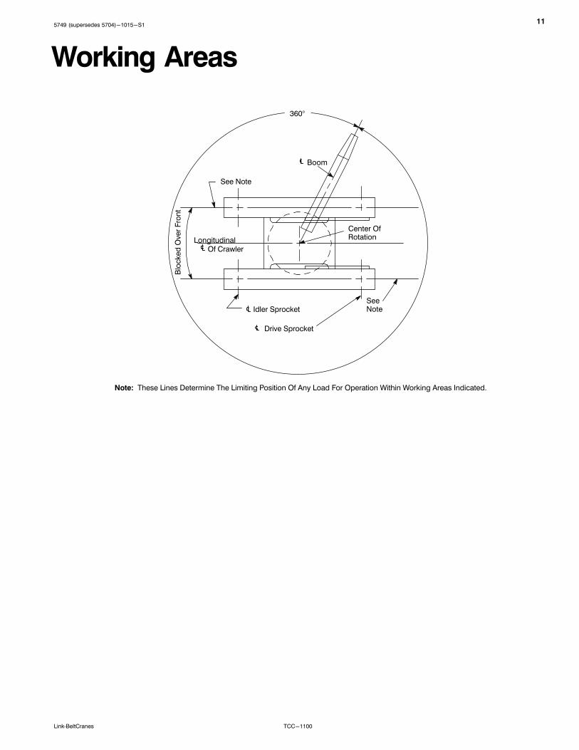
Working Areas
Boom
Blo
cked
Ove
r Fro
nt
Center Of Rotation
Of CrawlerLongitudinal
SeeNoteIdler Sprocket
Note: These Lines Determine The Limiting Position Of Any Load For Operation Within Working Areas Indicated.
Drive Sprocket
See Note
360°

125749 (supersedes 5704)-1015-S1
TCC-1100 Link‐BeltCranes
Boom Extend ModesBoom Mode “Amax1”
Boom Mode “Amax2”
Inner and center sections telescope simultaneously
Center, outer, and tip sections telescope simultaneously
Boom Mode “Standard”Inner, center, outer, and tip sections telescope simultaneously
BaseInnerCenterOuterTip
BaseCenterOuterTip
BaseInnerCenter
0 (0)5.0 (1.5)10.0 (3.0)15.0 (4.6)20.0 (6.1)25.0 (7.6)27.5 (8.4)
Boom Length - ft (m)Telescope Length - ft (m)
Telescope Length - ft (m)
Boom Length - ft (m)Telescope Length - ft (m)
40 (12.2)50 (15.2)60 (18.3)70 (21.3)80 (24.4)90 (27.4)95 (29.0)
0 (0)3.33 (1.0)6.66 (2.0)10.00 (3.0)13.33 (4.1)16.66 (5.1)20.00 (6.1)23.33 (7.1)27.50 (8.4)
40 (12.2)50 (15.2)60 (18.3)70 (21.3)80 (24.4)90 (27.4)100 (30.5)110 (33.5)
122.5 (37.3)
0 (0)2.5 (0.8)5.0 (1.5)7.5 (2.3)10.0 (3.0)12.5 (3.8)15.0 (4.6)17.5 (5.3)20.0 (6.1)22.5 (6.9)25.0 (7.6)27.5 (8.4)
0 (0)5.0 (1.5)10.0 (3.0)15.0 (4.6)20.0 (6.1)25.0 (7.6)27.5 (8.4)
0 (0)3.33 (1.0)6.66 (2.0)10.00 (3.0)13.33 (4.1)16.66 (5.1)20.00 (6.1)23.33 (7.1)27.50 (8.4)
0 (0)3.33 (1.0)6.66 (2.0)10.00 (3.0)13.33 (4.1)16.66 (5.1)20.00 (6.1)23.33 (7.1)27.50 (8.4)
0 (0)2.5 (0.8)5.0 (1.5)7.5 (2.3)10.0 (3.0)12.5 (3.8)15.0 (4.6)17.5 (5.3)20.0 (6.1)22.5 (6.9)25.0 (7.6)27.5 (8.4)
0 (0)2.5 (0.8)5.0 (1.5)7.5 (2.3)10.0 (3.0)12.5 (3.8)15.0 (4.6)17.5 (5.3)20.0 (6.1)22.5 (6.9)25.0 (7.6)27.5 (8.4)
0 (0)2.5 (0.8)5.0 (1.5)7.5 (2.3)10.0 (3.0)12.5 (3.8)15.0 (4.6)17.5 (5.3)20.0 (6.1)22.5 (6.9)25.0 (7.6)27.5 (8.4)
40 (12.2)50 (15.2)60 (18.3)70 (21.3)80 (24.4)90 (27.4)100 (30.5)110 (33.5)120 (36.6)130 (39.6)140 (42.7)150 (45.7)
Boom Length - ft (m)

135749 (supersedes 5704)-1015-S1
TCC-1100Link‐BeltCranes
Working Range DiagramsMain Boom
40' (12.19m)
10'(3.05m)
20'(6.10m)
30'(9.14m)
40'(12.19m)
50'(15.24m)
60'(18.29m)
70'(21.34m)
80'(24.38m)
90'(27.43m)
100'(30.48m)
110'(33.53m)
120'(36.58m)
130'(39.62m)
140'(42.67m)
10' (3.05m)
20' (6.10m)
30' (9.14m)
50' (15.24m)
60' (18.29m)
70' (21.34m)
80' (24.38m)
90' (27.43m)
100' (30.48m)
110' (33.53m)
120' (36.58m)
130' (39.62m)
140' (42.67m)
150' (45.72m)
160' (48.77m)
170' (51.82m)
150' (45.72m)
140' (42.67m)
130' (39.62m)
120' (36.58m)
110' (33.53m)
100' (30.48m)
90' (27.43m)
80' (24.38m)
70' (21.34m)
60' (18.29m)
50' (15.24m)
40' (12.19m)
Of Rotation
ÁÁ20°
0°
ÁÁ40°
ÁÁÁÁ
50°
ÁÁÁ60°
70°
ÁÁ80°
122.5' (37.34m) “Amax2”
95' (28.96m) “Amax1”
ÁÁ10°
ÁÁÁÁ
30°
Operating Radius From Centerline Of Rotation
Heig
ht O
f B
oo
m H
ead
Ab
ove
Gro
un
d
Main
Bo
om
Len
gth

145749 (supersedes 5704)-1015-S1
TCC-1100 Link‐BeltCranes
150' Main Boom + 10' Fly
0°
10°
20°
30°
40°
50°
60°
70°
80°
Operating Radius From Centerline Of Rotation In Feet
45° Offset
30° Offset15° Offset
2° Offset
40' (12.19m)
10' (3.05m)
20' (6.10m)
30' (9.14m)
50' (15.24m)
60' (18.29m)
70' (21.34m)
80' (24.38m)
90' (27.43m)
100' (30.48m)
110' (33.53m)
120' (36.58m)
130' (39.62m)
140' (42.67m)
150' (45.72m)
160' (48.77m)
170' (51.82m)
180' (54.86m)
Heig
ht
Of
Bo
om
Head
Ab
ove G
rou
nd
In
Fe
et
150' (45.72m) +10' (3.05m) Fly
140' (42.67m) +10' (3.05m) Fly
130' (39.62m) +10' (3.05m) Fly
120' (36.58m) +10' (3.05m) Fly
110' (33.53m) +10' (3.05m) Fly
100' (30.48m) +10' (3.05m) Fly
90' (27.43m) +10' (3.05m) Fly
80' (24.38m) +10' (3.05m) Fly
70' (21.34m) +10' (3.05m) Fly
60' (18.29m) +10' (3.05m) Fly
50' (15.24m) +10' (3.05m) Fly
40' (12.19m) +10' (3.05m) Fly
10'(3.05m)
20'(6.10m)
30'(9.14m)
40'(12.19m)
50'(15.24m)
60'(18.29m)
70'(21.34m)
80'(24.38m)
90'(27.43m)
100'(30.48m)
110'(33.53m)
120'(36.58m)
130'(39.62m)
140'(42.67m) Of Rotation
150'(45.72m)

155749 (supersedes 5704)-1015-S1
TCC-1100Link‐BeltCranes
120' Main Boom + 31-55' Fly
80°
70°
60°
50°
40°
30°
20°
10°
0°
Heig
ht
Of
Bo
om
Head
Ab
ove G
rou
nd
In
Fe
et
Operating Radius From Centerline Of Rotation In Feet
45° Offset
30° Offset15° Offset
2° Offset
40' (12.19m)
10' (3.05m)
20' (6.10m)
30' (9.14m)
50' (15.24m)
60' (18.29m)
70' (21.34m)
80' (24.38m)
90' (27.43m)
100' (30.48m)
110' (33.53m)
120' (36.58m)
130' (39.62m)
140' (42.67m)
150' (45.72m)
160' (48.77m)
170' (51.82m)
180' (54.86m)
190' (57.91m)
10'(3.05m)
20'(6.10m)
30'(9.14m)
40'(12.19m)
50'(15.24m)
60'(18.29m)
70'(21.34m)
80'(24.38m)
90'(27.43m)
100'(30.48m)
110'(33.53m)
120'(36.58m)
130'(39.62m)
140'(42.67m) Of Rotation
150'(45.72m)
160'(48.77m)
170'(51.82m)
120' (36.58m)Main Boom
120' (36.58m) +31' (9.45m) Fly
120' (36.58m) +55' (16.76m) Fly

165749 (supersedes 5704)-1015-S1
TCC-1100 Link‐BeltCranes
150' Main Boom + 31-55' Fly
80°
70°
60°
50°
40°
30°
20°
10°
0°
Heig
ht
Of
Bo
om
Head
Ab
ove G
rou
nd
In
Fe
et
Operating Radius From Centerline Of Rotation In Feet
45° Offset30° Offset
15° Offset
2° Offset
40' (12.19m)
10' (3.05m)
20' (6.10m)
30' (9.14m)
50' (15.24m)
60' (18.29m)
70' (21.34m)
80' (24.38m)
90' (27.43m)
100' (30.48m)
110' (33.53m)
120' (36.58m)
130' (39.62m)
140' (42.67m)
150' (45.72m)
160' (48.77m)
170' (51.82m)
180' (54.86m)
190' (57.91m)
150' (45.72m)Main Boom
150' (45.72m) +31' (9.45m) Fly
150' (45.72m) +55' (16.76m) Fly
200' (60.96m)
210' (64.01m)
220' (67.06m)
10'(3.05m)
20'(6.10m)
30'(9.14m)
40'(12.19m)
50'(15.24m)
60'(18.29m)
70'(21.34m)
80'(24.38m)
90'(27.43m)
100'(30.48m)
110'(33.53m)
120'(36.58m)
130'(39.62m)
140'(42.67m) Of Rotation
150'(45.72m)
160'(48.77m)
170'(51.82m)
180'(54.86m)
190'(57.91m)

175749 (supersedes 5704)-1015-S1
TCC-1100Link‐BeltCranes
Main Boom Load ChartsMain Boom Lift Capacity Chart - 360� Rotation - Fully Extended Tracks
ABC+A [76,000 lb (34 473kg)] Counterweight[All capacities are listed in kips (mt)]
LoadRadiusft (m)
Main Boom
LoadRadiusft (m)
Boom Length - ft (m)
40(12.2)
50(15.2)
60(18.3)
70(21.3)
80(24.4)
90(27.4)
100(30.5)
110(33.5)
120(36.6)
130(39.6)
140(42.7)
150(45.7)
10 221.0 107.2 105.4 101.5 10
(3.0) (100.2) (48.6) (47.8) (46.0) (3.0)
12 193.7 107.2 105.4 101.5 101.4 12
(3.7) (87.9) (48.6) (47.8) (46.0) (46.0) (3.7)
15 155.0 107.2 105.4 101.5 96.6 81.9 56.5 15
(4.6) (70.3) (48.6) (47.8) (46.0) (43.8) (37.1) (25.6) (4.6)
20 116.2 107.2 105.4 101.5 80.8 73.3 56.5 56.0 20
(6.1) (52.7) (48.6) (47.8) (46.0) (36.7) (33.2) (25.6) (25.4) (6.1)
25 93.0 93.0 93.0 87.8 69.0 62.7 56.3 56.0 58.0 25
(7.6) (42.2) (42.2) (42.2) (39.8) (31.3) (28.4) (25.5) (25.4) (26.3) (7.6)
30 74.3 74.1 73.7 73.3 59.9 55.0 53.5 56.0 51.3 48.6 38.4 30.0 30
(9.1) (33.7) (33.6) (33.4) (33.2) (27.2) (24.9) (24.3) (25.4) (23.3) (22.0) (17.4) (13.6) (9.1)
35 58.1 57.9 57.6 53.2 51.8 53.5 51.8 45.4 43.1 38.4 30.0 35
(10.7) (26.4) (26.3) (26.1) (24.1) (23.5) (24.3) (23.5) (20.6) (19.5) (17.4) (13.6) (10.7)
40 48.9 49.9 50.6 51.0 46.7 49.5 46.3 40.6 38.5 37.0 30.0 40
(12.2) (22.2) (22.6) (23.0) (23.1) (21.2) (22.5) (21.0) (18.4) (17.5) (16.8) (13.6) (12.2)
45 41.8 42.4 42.9 42.4 41.5 41.5 36.5 34.7 33.4 30.0 45
(13.7) (19.0) (19.2) (19.5) (19.2) (18.8) (18.8) (16.6) (15.7) (15.1) (13.6) (13.7)
50 35.6 36.3 36.7 37.1 35.5 35.6 33.0 31.4 30.2 29.1 50
(15.2) (16.1) (16.5) (16.6) (16.8) (16.1) (16.1) (15.0) (14.2) (13.7) (13.2) (15.2)
55 31.4 31.8 32.2 30.7 30.8 30.0 28.5 27.5 26.5 55
(16.8) (14.2) (14.4) (14.6) (13.9) (14.0) (13.6) (12.9) (12.5) (12.0) (16.8)
60 27.5 27.9 28.2 27.9 26.9 26.9 26.0 25.1 24.2 60
(18.3) (12.5) (12.7) (12.8) (12.7) (12.2) (12.2) (11.8) (11.4) (11.0) (18.3)
65 24.6 24.9 25.2 23.7 23.7 23.7 23.0 22.2 65
(19.8) (11.2) (11.3) (11.4) (10.8) (10.8) (10.8) (10.4) (10.1) (19.8)
70 21.9 22.2 22.4 21.9 21.0 21.0 21.0 20.3 70
(21.3) (9.9) (10.1) (10.2) (9.9) (9.5) (9.5) (9.5) (9.2) (21.3)
75 20.0 20.2 20.4 18.8 18.9 18.9 18.7 75
(22.9) (9.1) (9.2) (9.3) (8.5) (8.6) (8.6) (8.5) (22.9)
80 18.0 18.2 18.4 17.3 16.9 16.9 17.0 80
(24.4) (8.2) (8.3) (8.3) (7.8) (7.7) (7.7) (7.7) (24.4)
85 16.5 16.6 16.1 15.2 15.2 15.2 85
(25.9) (7.5) (7.5) (7.3) (6.9) (6.9) (6.9) (25.9)
90 14.9 15.1 15.1 13.6 13.7 13.7 90
(27.4) (6.8) (6.8) (6.8) (6.2) (6.2) (6.2) (27.4)
95 13.8 13.9 12.3 12.3 12.4 95
(29.0) (6.3) (6.3) (5.6) (5.6) (5.6) (29.0)
100 12.6 12.7 11.1 11.1 11.2 100
(30.5) (5.7) (5.8) (5.0) (5.0) (5.1) (30.5)
105 11.7 10.0 10.1 10.1 105
(32.0) (5.3) (4.5) (4.6) (4.6) (32.0)
110 10.7 9.0 9.1 9.1 110
(33.5) (4.9) (4.1) (4.1) (4.1) (33.5)
115 8.2 8.2 8.3 115
(35.1) (3.7) (3.7) (3.8) (35.1)
120 7.4 7.4 7.5 120
(36.6) (3.4) (3.4) (3.4) (36.6)
125 6.7 6.7 125
(38.1) (3.0) (3.0) (38.1)
130 6.0 6.1 130
(39.6) (2.7) (2.8) (39.6)
135 5.5 135
(41.1) (2.5) (41.1)
140 4.9 140
(42.7) (2.2) (42.7)
This material is supplied for reference use only. Operator must refer to in-cab Crane Rating Manual and Operator's Manual to determine allowablecrane lifting capacities and assembly and operating procedures.

185749 (supersedes 5704)-1015-S1
TCC-1100 Link‐BeltCranes
Main Boom Lift Capacity Chart - 360� Rotation - Fully Extended TracksABC+A [76,000 lb (34 473kg)] Counterweight
[All capacities are listed in kips (mt)]
LoadRadiusft (m)
Main Boom + 10 ft Manual Offset Fly (2 Offsets)
LoadRadiusft (m)
Boom Length ft (m)
40(12.2)
50(15.2)
60(18.3)
70(21.3)
80(24.4)
90(27.4)
100(30.5)
110(33.5)
120(36.6)
130(39.6)
140(42.7)
150(45.7)
10 62.4 62.3 10
(3.0) (28.3) (28.3) (3.0)
12 62.4 62.3 62.3 12
(3.7) (28.3) (28.3) (28.3) (3.7)
15 62.4 62.3 62.3 62.3 62.2 15
(4.6) (28.3) (28.3) (28.3) (28.3) (28.2) (4.6)
20 61.6 62.3 62.3 62.3 62.2 62.2 20
(6.1) (27.9) (28.3) (28.3) (28.3) (28.2) (28.2) (6.1)
25 56.1 61.6 62.3 62.3 62.2 62.2 62.1 57.1 53.3 25
(7.6) (25.4) (27.9) (28.3) (28.3) (28.2) (28.2) (28.2) (25.9) (24.2) (7.6)
30 51.7 56.9 61.3 62.3 62.2 62.2 62.1 50.9 47.1 39.2 31.0 24.1 30
(9.1) (23.5) (25.8) (27.8) (28.3) (28.2) (28.2) (28.2) (23.1) (21.4) (17.8) (14.1) (10.9) (9.1)
35 48.5 53.1 57.4 60.6 60.5 60.4 55.6 45.9 41.8 39.2 31.0 24.1 35
(10.7) (22.0) (24.1) (26.0) (27.5) (27.4) (27.4) (25.2) (20.8) (19.0) (17.8) (14.1) (10.9) (10.7)
40 46.4 49.7 49.7 49.6 49.5 49.4 49.3 41.8 37.6 35.5 31.0 24.1 40
(12.2) (21.0) (22.5) (22.5) (22.5) (22.5) (22.4) (22.4) (19.0) (17.1) (16.1) (14.1) (10.9) (12.2)
45 41.6 41.6 41.6 41.5 41.4 41.4 38.2 33.8 32.0 30.7 24.1 45
(13.7) (18.9) (18.9) (18.9) (18.8) (18.8) (18.8) (17.3) (15.3) (14.5) (13.9) (10.9) (13.7)
50 35.6 35.5 35.5 35.5 35.4 35.3 35.1 30.6 28.9 27.8 24.1 50
(15.2) (16.1) (16.1) (16.1) (16.1) (16.1) (16.0) (15.9) (13.9) (13.1) (12.6) (10.9) (15.2)
55 30.6 30.6 30.6 30.5 30.4 27.8 26.3 25.3 24.1 55
(16.8) (13.9) (13.9) (13.9) (13.8) (13.8) (12.6) (11.9) (11.5) (10.9) (16.8)
60 26.7 26.7 26.7 26.6 26.5 25.3 24.0 23.0 20.0 60
(18.3) (12.1) (12.1) (12.1) (12.1) (12.0) (11.5) (10.9) (10.4) (9.1) (18.3)
65 23.5 23.4 23.4 23.3 23.2 21.9 21.0 20.0 65
(19.8) (10.7) (10.6) (10.6) (10.6) (10.5) (9.9) (9.5) (9.1) (19.8)
70 20.8 20.7 20.7 20.7 20.6 20.3 19.5 18.7 70
(21.3) (9.4) (9.4) (9.4) (9.4) (9.3) (9.2) (8.8) (8.5) (21.3)
75 18.5 18.5 18.5 18.5 18.4 17.9 17.2 75
(22.9) (8.4) (8.4) (8.4) (8.4) (8.3) (8.1) (7.8) (22.9)
80 16.5 16.5 16.5 16.5 16.5 16.4 15.8 80
(24.4) (7.5) (7.5) (7.5) (7.5) (7.5) (7.4) (7.2) (24.4)
85 14.8 14.8 14.8 14.7 14.7 14.6 85
(25.9) (6.7) (6.7) (6.7) (6.7) (6.7) (6.6) (25.9)
90 13.3 13.3 13.2 13.2 13.2 13.2 90
(27.4) (6.0) (6.0) (6.0) (6.0) (6.0) (6.0) (27.4)
95 11.9 11.9 11.9 11.9 11.8 95
(29.0) (5.4) (5.4) (5.4) (5.4) (5.4) (29.0)
100 10.7 10.7 10.7 10.7 10.6 100
(30.5) (4.9) (4.9) (4.9) (4.9) (4.8) (30.5)
105 9.6 9.6 9.6 9.6 105
(32.0) (4.4) (4.4) (4.4) (4.4) (32.0)
110 8.7 8.7 8.6 8.6 110
(33.5) (3.9) (3.9) (3.9) (3.9) (33.5)
115 7.8 7.8 7.7 115
(35.1) (3.5) (3.5) (3.5) (35.1)
120 7.0 7.0 6.9 120
(36.6) (3.2) (3.2) (3.1) (36.6)
125 6.2 6.2 125
(38.1) (2.8) (2.8) (38.1)
130 5.6 5.6 130
(39.6) (2.5) (2.5) (39.6)
135 4.9 135
(41.1) (2.2) (41.1)
140 4.4 140
(42.7) (2.0) (42.7)
145 3.9 145
(44.2) (1.8) (44.2)
This material is supplied for reference use only. Operator must refer to in-cab Crane Rating Manual and Operator's Manual to determine allowablecrane lifting capacities and assembly and operating procedures.
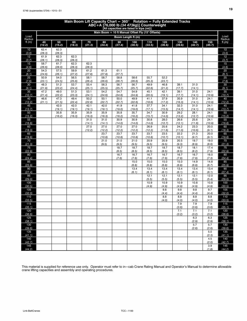
195749 (supersedes 5704)-1015-S1
TCC-1100Link‐BeltCranes
Main Boom Lift Capacity Chart - 360� Rotation - Fully Extended TracksABC+A [76,000 lb (34 473kg)] Counterweight
[All capacities are listed in kips (mt)]
LoadRadiusft (m)
Main Boom + 10 ft Manual Offset Fly (15° Offsets)
LoadRadiusft (m)
Boom Length ft (m)
40(12.2)
50(15.2)
60(18.3)
70(21.3)
80(24.4)
90(27.4)
100(30.5)
110(33.5)
120(36.6)
130(39.6)
140(42.7)
150(45.7)
ft (m)
10 62.4 62.3 10
(3.0) (28.3) (28.3) (3.0)
12 61.9 62.3 62.3 12
(3.7) (28.1) (28.3) (28.3) (3.7)
15 58.7 61.7 62.3 62.3 15
(4.6) (26.6) (28.0) (28.3) (28.3) (4.6)
20 54.3 57.5 59.9 61.2 61.3 61.1 20
(6.1) (24.6) (26.1) (27.2) (27.8) (27.8) (27.7) (6.1)
25 50.9 54.0 56.5 58.1 58.7 58.8 58.6 55.7 52.2 25
(7.6) (23.1) (24.5) (25.6) (26.4) (26.6) (26.7) (26.6) (25.3) (23.7) (7.6)
30 48.3 51.2 53.7 55.4 56.3 56.7 56.7 49.9 46.8 39.1 31.0 30
(9.1) (21.9) (23.2) (24.4) (25.1) (25.5) (25.7) (25.7) (22.6) (21.2) (17.7) (14.1) (9.1)
35 47.2 49.0 51.3 53.1 54.2 54.7 54.9 45.1 42.1 39.1 31.0 24.1 35
(10.7) (21.4) (22.2) (23.3) (24.1) (24.6) (24.8) (24.9) (20.5) (19.1) (17.7) (14.1) (10.9) (10.7)
40 46.6 47.3 49.4 50.2 50.1 50.0 49.9 41.1 37.9 35.9 31.0 24.1 40
(12.2) (21.1) (21.5) (22.4) (22.8) (22.7) (22.7) (22.6) (18.6) (17.2) (16.3) (14.1) (10.9) (12.2)
45 42.0 42.0 42.1 42.0 41.9 41.8 37.7 34.1 32.3 31.0 24.1 45
(13.7) (19.1) (19.1) (19.1) (19.1) (19.0) (19.0) (17.1) (15.5) (14.7) (14.1) (10.9) (13.7)
50 35.8 35.9 35.9 35.9 35.8 35.7 34.7 30.9 29.2 28.1 24.1 50
(15.2) (16.2) (16.3) (16.3) (16.3) (16.2) (16.2) (15.7) (14.0) (13.2) (12.7) (10.9) (15.2)
55 31.0 31.0 30.9 30.9 30.8 28.0 26.6 25.6 24.1 55
(16.8) (14.1) (14.1) (14.0) (14.0) (14.0) (12.7) (12.1) (11.6) (10.9) (16.8)
60 27.0 27.0 27.0 27.0 26.9 25.6 24.2 23.3 20.0 60
(18.3) (12.2) (12.2) (12.2) (12.2) (12.2) (11.6) (11.0) (10.6) (9.1) (18.3)
65 23.7 23.7 23.7 23.7 23.5 22.2 21.3 20.0 65
(19.8) (10.8) (10.8) (10.8) (10.8) (10.7) (10.1) (9.7) (9.1) (19.8)
70 21.0 21.0 21.0 20.9 20.9 20.5 19.7 19.0 70
(21.3) (9.5) (9.5) (9.5) (9.5) (9.5) (9.3) (8.9) (8.6) (21.3)
75 18.7 18.7 18.7 18.7 18.7 18.1 17.4 75
(22.9) (8.5) (8.5) (8.5) (8.5) (8.5) (8.2) (7.9) (22.9)
80 16.7 16.7 16.7 16.7 16.7 16.7 16.0 80
(24.4) (7.6) (7.6) (7.6) (7.6) (7.6) (7.6) (7.3) (24.4)
85 15.0 15.0 15.0 15.0 14.9 14.8 85
(25.9) (6.8) (6.8) (6.8) (6.8) (6.8) (6.7) (25.9)
90 13.4 13.4 13.4 13.4 13.4 13.4 90
(27.4) (6.1) (6.1) (6.1) (6.1) (6.1) (6.1) (27.4)
95 12.1 12.1 12.1 12.1 12.0 95
(29.0) (5.5) (5.5) (5.5) (5.5) (5.4) (29.0)
100 10.9 10.9 10.9 10.8 10.8 100
(30.5) (4.9) (4.9) (4.9) (4.9) (4.9) (30.5)
105 9.8 9.8 9.8 9.7 105
(32.0) (4.4) (4.4) (4.4) (4.4) (32.0)
110 8.8 8.8 8.8 8.8 110
(33.5) (4.0) (4.0) (4.0) (4.0) (33.5)
115 7.9 7.9 7.9 115
(35.1) (3.6) (3.6) (3.6) (35.1)
120 7.1 7.1 7.1 120
(36.6) (3.2) (3.2) (3.2) (36.6)
125 6.3 6.3 125
(38.1) (2.9) (2.9) (38.1)
130 5.7 5.7 130
(39.6) (2.6) (2.6) (39.6)
135 5.0 135
(41.1) (2.3) (41.1)
140 4.5 140
(42.7) (2.0) (42.7)
145 3.9 145
(44.2) (1.8) (44.2)
This material is supplied for reference use only. Operator must refer to in-cab Crane Rating Manual and Operator's Manual to determine allowablecrane lifting capacities and assembly and operating procedures.
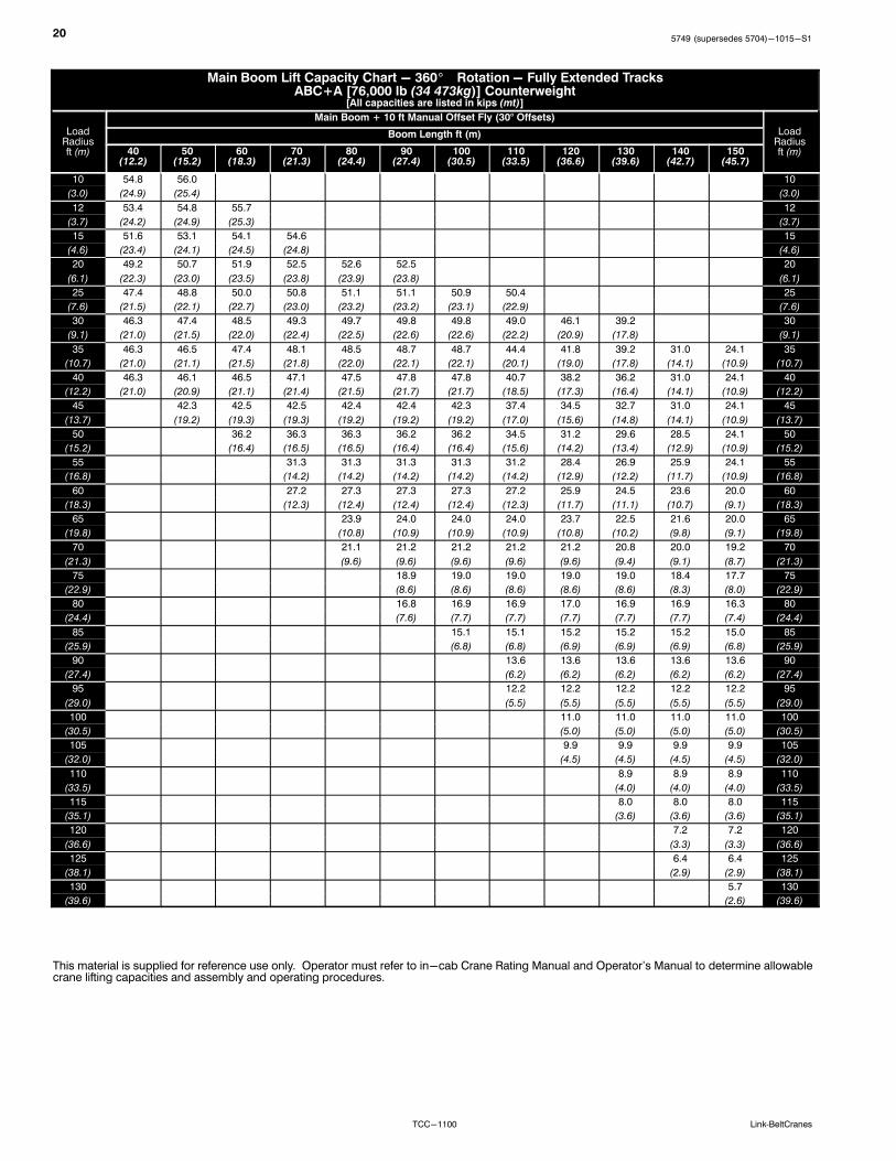
205749 (supersedes 5704)-1015-S1
TCC-1100 Link‐BeltCranes
Main Boom Lift Capacity Chart - 360� Rotation - Fully Extended TracksABC+A [76,000 lb (34 473kg)] Counterweight
[All capacities are listed in kips (mt)]
LoadRadiusft (m)
Main Boom + 10 ft Manual Offset Fly (30° Offsets)
LoadRadiusft (m)
Boom Length ft (m)
40(12.2)
50(15.2)
60(18.3)
70(21.3)
80(24.4)
90(27.4)
100(30.5)
110(33.5)
120(36.6)
130(39.6)
140(42.7)
150(45.7)
10 54.8 56.0 10
(3.0) (24.9) (25.4) (3.0)
12 53.4 54.8 55.7 12
(3.7) (24.2) (24.9) (25.3) (3.7)
15 51.6 53.1 54.1 54.6 15
(4.6) (23.4) (24.1) (24.5) (24.8) (4.6)
20 49.2 50.7 51.9 52.5 52.6 52.5 20
(6.1) (22.3) (23.0) (23.5) (23.8) (23.9) (23.8) (6.1)
25 47.4 48.8 50.0 50.8 51.1 51.1 50.9 50.4 25
(7.6) (21.5) (22.1) (22.7) (23.0) (23.2) (23.2) (23.1) (22.9) (7.6)
30 46.3 47.4 48.5 49.3 49.7 49.8 49.8 49.0 46.1 39.2 30
(9.1) (21.0) (21.5) (22.0) (22.4) (22.5) (22.6) (22.6) (22.2) (20.9) (17.8) (9.1)
35 46.3 46.5 47.4 48.1 48.5 48.7 48.7 44.4 41.8 39.2 31.0 24.1 35
(10.7) (21.0) (21.1) (21.5) (21.8) (22.0) (22.1) (22.1) (20.1) (19.0) (17.8) (14.1) (10.9) (10.7)
40 46.3 46.1 46.5 47.1 47.5 47.8 47.8 40.7 38.2 36.2 31.0 24.1 40
(12.2) (21.0) (20.9) (21.1) (21.4) (21.5) (21.7) (21.7) (18.5) (17.3) (16.4) (14.1) (10.9) (12.2)
45 42.3 42.5 42.5 42.4 42.4 42.3 37.4 34.5 32.7 31.0 24.1 45
(13.7) (19.2) (19.3) (19.3) (19.2) (19.2) (19.2) (17.0) (15.6) (14.8) (14.1) (10.9) (13.7)
50 36.2 36.3 36.3 36.2 36.2 34.5 31.2 29.6 28.5 24.1 50
(15.2) (16.4) (16.5) (16.5) (16.4) (16.4) (15.6) (14.2) (13.4) (12.9) (10.9) (15.2)
55 31.3 31.3 31.3 31.3 31.2 28.4 26.9 25.9 24.1 55
(16.8) (14.2) (14.2) (14.2) (14.2) (14.2) (12.9) (12.2) (11.7) (10.9) (16.8)
60 27.2 27.3 27.3 27.3 27.2 25.9 24.5 23.6 20.0 60
(18.3) (12.3) (12.4) (12.4) (12.4) (12.3) (11.7) (11.1) (10.7) (9.1) (18.3)
65 23.9 24.0 24.0 24.0 23.7 22.5 21.6 20.0 65
(19.8) (10.8) (10.9) (10.9) (10.9) (10.8) (10.2) (9.8) (9.1) (19.8)
70 21.1 21.2 21.2 21.2 21.2 20.8 20.0 19.2 70
(21.3) (9.6) (9.6) (9.6) (9.6) (9.6) (9.4) (9.1) (8.7) (21.3)
75 18.9 19.0 19.0 19.0 19.0 18.4 17.7 75
(22.9) (8.6) (8.6) (8.6) (8.6) (8.6) (8.3) (8.0) (22.9)
80 16.8 16.9 16.9 17.0 16.9 16.9 16.3 80
(24.4) (7.6) (7.7) (7.7) (7.7) (7.7) (7.7) (7.4) (24.4)
85 15.1 15.1 15.2 15.2 15.2 15.0 85
(25.9) (6.8) (6.8) (6.9) (6.9) (6.9) (6.8) (25.9)
90 13.6 13.6 13.6 13.6 13.6 90
(27.4) (6.2) (6.2) (6.2) (6.2) (6.2) (27.4)
95 12.2 12.2 12.2 12.2 12.2 95
(29.0) (5.5) (5.5) (5.5) (5.5) (5.5) (29.0)
100 11.0 11.0 11.0 11.0 100
(30.5) (5.0) (5.0) (5.0) (5.0) (30.5)
105 9.9 9.9 9.9 9.9 105
(32.0) (4.5) (4.5) (4.5) (4.5) (32.0)
110 8.9 8.9 8.9 110
(33.5) (4.0) (4.0) (4.0) (33.5)
115 8.0 8.0 8.0 115
(35.1) (3.6) (3.6) (3.6) (35.1)
120 7.2 7.2 120
(36.6) (3.3) (3.3) (36.6)
125 6.4 6.4 125
(38.1) (2.9) (2.9) (38.1)
130 5.7 130
(39.6) (2.6) (39.6)
This material is supplied for reference use only. Operator must refer to in-cab Crane Rating Manual and Operator's Manual to determine allowablecrane lifting capacities and assembly and operating procedures.

215749 (supersedes 5704)-1015-S1
TCC-1100Link‐BeltCranes
Main Boom Lift Capacity Chart - 360� Rotation - Fully Extended TracksABC+A [76,000 lb (34 473kg)] Counterweight
[All capacities are listed in kips (mt)]
LoadRadiusft (m)
Main Boom + 10 ft Manual Offset Fly (45° Offsets)
LoadRadiusft (m)
Boom Length ft (m)
40(12.2)
50(15.2)
60(18.3)
70(21.3)
80(24.4)
90(27.4)
100(30.5)
110(33.5)
120(36.6)
130(39.6)
140(42.7)
150(45.7)
12 48.6 49.2 12
(3.7) (22.0) (22.3) (3.7)
15 47.7 48.3 48.7 15
(4.6) (21.6) (21.9) (22.1) (4.6)
20 46.6 47.1 47.6 47.7 47.7 47.5 20
(6.1) (21.1) (21.4) (21.6) (21.6) (21.6) (21.5) (6.1)
25 46.1 46.3 46.7 46.9 46.9 46.7 46.5 25
(7.6) (20.9) (21.0) (21.2) (21.3) (21.3) (21.2) (21.1) (7.6)
30 46.1 46.0 46.2 46.3 46.3 46.1 45.9 45.5 44.5 30
(9.1) (20.9) (20.9) (21.0) (21.0) (21.0) (20.9) (20.8) (20.6) (20.2) (9.1)
35 46.0 45.9 45.9 45.8 45.7 45.5 44.1 41.6 39.4 31.2 35
(10.7) (20.9) (20.8) (20.8) (20.8) (20.7) (20.6) (20.0) (18.9) (17.9) (14.2) (10.7)
40 46.0 45.9 45.7 45.5 45.3 45.1 40.5 38.1 36.1 31.2 24.4 40
(12.2) (20.9) (20.8) (20.7) (20.6) (20.5) (20.5) (18.4) (17.3) (16.4) (14.2) (11.1) (12.2)
45 42.7 42.8 42.8 42.8 42.7 37.2 34.9 33.1 31.2 24.4 45
(13.7) (19.4) (19.4) (19.4) (19.4) (19.4) (16.9) (15.8) (15.0) (14.2) (11.1) (13.7)
50 36.5 36.6 36.6 36.6 34.4 31.6 30.0 28.9 24.4 50
(15.2) (16.6) (16.6) (16.6) (16.6) (15.6) (14.3) (13.6) (13.1) (11.1) (15.2)
55 31.4 31.6 31.6 31.6 31.5 28.8 27.3 26.3 24.4 55
(16.8) (14.2) (14.3) (14.3) (14.3) (14.3) (13.1) (12.4) (11.9) (11.1) (16.8)
60 27.5 27.5 27.5 27.5 26.2 24.9 23.9 20.1 60
(18.3) (12.5) (12.5) (12.5) (12.5) (11.9) (11.3) (10.8) (9.1) (18.3)
65 24.2 24.2 24.2 24.0 22.7 21.9 20.1 65
(19.8) (11.0) (11.0) (11.0) (10.9) (10.3) (9.9) (9.1) (19.8)
70 21.4 21.4 21.4 20.9 20.3 19.5 70
(21.3) (9.7) (9.7) (9.7) (9.5) (9.2) (8.8) (21.3)
75 19.1 19.2 19.2 19.2 18.6 17.9 75
(22.9) (8.7) (8.7) (8.7) (8.7) (8.4) (8.1) (22.9)
80 17.1 17.1 17.1 17.1 16.5 80
(24.4) (7.8) (7.8) (7.8) (7.8) (7.5) (24.4)
85 15.3 15.3 15.3 15.2 85
(25.9) (6.9) (6.9) (6.9) (6.9) (25.9)
90 13.7 13.7 13.8 13.7 90
(27.4) (6.2) (6.2) (6.3) (6.2) (27.4)
95 12.3 12.4 12.4 95
(29.0) (5.6) (5.6) (5.6) (29.0)
100 11.1 11.1 100
(30.5) (5.0) (5.0) (30.5)
105 10.0 105
(32.0) (4.5) (32.0)
This material is supplied for reference use only. Operator must refer to in-cab Crane Rating Manual and Operator's Manual to determine allowablecrane lifting capacities and assembly and operating procedures.

225749 (supersedes 5704)-1015-S1
TCC-1100 Link‐BeltCranes
Jib Attachment Load ChartsMain Boom Lift Capacity Chart - 360� Rotation - Fully Extended Tracks
ABC+A [76,000 lb (34 473kg)] Counterweight[All capacities are listed in kips (mt)]
Load Radiusft (m)
120 ft Main Boom Length
Load Radiusft (m)
31 ft Manual Offset Fly 55 ft Manual Offset Fly
2 15 30 45 2 15 30 45
30 29.7 30
(9.1) (13.5) (9.1)
35 28.3 13.6 35
(10.7) (12.8) (6.2) (10.7)
40 27.0 20.3 13.1 40
(12.2) (12.2) (9.2) (5.9) (12.2)
45 25.8 19.7 16.9 12.7 45
(13.7) (11.7) (8.9) (7.7) (5.8) (13.7)
50 24.7 19.1 16.5 14.8 12.2 10.4 50
(15.2) (11.2) (8.7) (7.5) (6.7) (5.5) (4.7) (15.2)
55 23.6 18.5 16.1 14.6 11.8 10.1 55
(16.8) (10.7) (8.4) (7.3) (6.6) (5.4) (4.6) (16.8)
60 22.6 18.0 15.8 14.4 11.4 9.8 60
(18.3) (10.3) (8.2) (7.2) (6.5) (5.2) (4.4) (18.3)
65 20.1 17.5 15.5 14.3 11.1 9.6 8.3 65
(19.8) (9.1) (7.9) (7.0) (6.5) (5.0) (4.4) (3.8) (19.8)
70 29.5 17.0 15.2 14.1 10.7 9.3 8.2 70
(21.3) (13.4) (7.7) (6.9) (6.4) (4.9) (4.2) (3.7) (21.3)
75 18.8 16.6 14.9 14.0 10.4 9.1 8.0 7.3 75
(22.9) (8.5) (7.5) (6.8) (6.4) (4.7) (4.1) (3.6) (3.3) (22.9)
80 17.4 16.2 14.7 13.9 10.1 8.8 7.8 7.2 80
(24.4) (7.9) (7.3) (6.7) (6.3) (4.6) (4.0) (3.5) (3.3) (24.4)
85 15.6 15.8 14.5 13.9 9.8 8.6 7.7 7.2 85
(25.9) (7.1) (7.2) (6.6) (6.3) (4.4) (3.9) (3.5) (3.3) (25.9)
90 14.1 14.7 14.3 13.8 9.5 8.4 7.6 7.1 90
(27.4) (6.4) (6.7) (6.5) (6.3) (4.3) (3.8) (3.4) (3.2) (27.4)
95 12.8 13.3 13.7 13.8 9.2 8.2 7.5 7.0 95
(29.0) (5.8) (6.0) (6.2) (6.3) (4.2) (3.7) (3.4) (3.2) (29.0)
100 11.6 12.0 12.4 12.7 9.0 8.1 7.4 7.0 100
(30.5) (5.3) (5.4) (5.6) (5.8) (4.1) (3.7) (3.4) (3.2) (30.5)
105 10.5 10.9 11.2 11.4 8.8 7.9 7.3 6.9 105
(32.0) (4.8) (4.9) (5.1) (5.2) (4.0) (3.6) (3.3) (3.1) (32.0)
110 9.5 9.9 10.2 10.3 8.5 7.8 7.2 6.9 110
(33.5) (4.3) (4.5) (4.6) (4.7) (3.9) (3.5) (3.3) (3.1) (33.5)
115 8.7 9.0 9.2 9.3 8.3 7.6 7.1 6.9 115
(35.1) (3.9) (4.1) (4.2) (4.2) (3.8) (3.4) (3.2) (3.1) (35.1)
120 7.9 8.1 8.3 8.1 7.5 7.1 6.9 120
(36.6) (3.6) (3.7) (3.8) (3.7) (3.4) (3.2) (3.1) (36.6)
125 7.1 7.4 7.5 8.0 7.4 7.0 6.9 125
(38.1) (3.2) (3.4) (3.4) (3.6) (3.4) (3.2) (3.1) (38.1)
130 6.5 6.7 6.8 7.3 7.3 7.0 6.9 130
(39.6) (2.9) (3.0) (3.1) (3.3) (3.3) (3.2) (3.1) (39.6)
135 5.9 6.0 6.7 7.1 7.0 6.9 135
(41.1) (2.7) (2.7) (3.0) (3.2) (3.2) (3.1) (41.1)
140 5.3 5.4 6.1 6.5 6.8 6.9 140
(42.7) (2.4) (2.4) (2.8) (2.9) (3.1) (3.1) (42.7)
145 5.6 5.9 6.1 145
(44.2) (2.5) (2.7) (2.8) (44.2)
150 5.1 5.4 5.5 150
(45.7) (2.3) (2.4) (2.5) (45.7)
155 4.6 4.9 5.0 155
(47.2) (2.1) (2.2) (2.3) (47.2)
This material is supplied for reference use only. Operator must refer to in-cab Crane Rating Manual and Operator's Manual to determine allowablecrane lifting capacities and assembly and operating procedures.

235749 (supersedes 5704)-1015-S1
TCC-1100Link‐BeltCranes
Main Boom Lift Capacity Chart - 360� Rotation - Fully Extended TracksABC+A [76,000 lb (34 473kg)] Counterweight
[All capacities are listed in kips (mt)]
Load Radiusft (m)
150 ft Main Boom Length
Load Radiusft (m)
31 ft Manual Offset Fly 55 ft Manual Offset Fly
2 15 30 45 2 15 30 45
35 16.1 35(10.7) (7.3) (10.7)
40 16.1 10.2 40(12.2) (7.3) (4.6) (12.2)
45 16.1 16.2 10.0 45(13.7) (7.3) (7.3) (4.5) (13.7)
50 16.1 16.2 14.8 9.8 50(15.2) (7.3) (7.3) (6.7) (4.4) (15.2)
55 16.1 16.1 14.6 13.6 9.7 8.6 55(16.8) (7.3) (7.3) (6.6) (6.2) (4.4) (3.9) (16.8)
60 16.1 15.9 14.4 13.4 9.5 8.4 60(18.3) (7.3) (7.2) (6.5) (6.1) (4.3) (3.8) (18.3)
65 16.1 15.6 14.2 13.3 9.3 8.3 65(19.8) (7.3) (7.1) (6.4) (6.0) (4.2) (3.8) (19.8)
70 16.1 15.4 14.0 13.2 9.1 8.1 7.3 70(21.3) (7.3) (7.0) (6.4) (6.0) (4.1) (3.7) (3.3) (21.3)
75 16.1 15.2 13.9 13.1 9.0 8.0 7.2 75(22.9) (7.3) (6.9) (6.3) (5.9) (4.1) (3.6) (3.3) (22.9)
80 14.9 15.0 13.7 13.1 8.8 7.9 7.1 6.6 80(24.4) (6.8) (6.8) (6.2) (5.9) (4.0) (3.6) (3.2) (3.0) (24.4)
85 13.8 14.2 13.6 13.0 8.6 7.8 7.0 6.6 85(25.9) (6.3) (6.4) (6.2) (5.9) (3.9) (3.5) (3.2) (3.0) (25.9)
90 12.7 13.1 13.5 13.0 8.5 7.6 6.9 6.5 90(27.4) (5.8) (5.9) (6.1) (5.9) (3.9) (3.4) (3.1) (2.9) (27.4)
95 11.7 12.1 12.5 12.9 8.3 7.5 6.9 6.5 95(29.0) (5.3) (5.5) (5.7) (5.9) (3.8) (3.4) (3.1) (2.9) (29.0)100 10.8 11.2 11.6 11.9 8.2 7.4 6.8 6.4 100
(30.5) (4.9) (5.1) (5.3) (5.4) (3.7) (3.4) (3.1) (2.9) (30.5)105 10.0 10.3 10.7 11.0 8.1 7.3 6.7 6.4 105
(32.0) (4.5) (4.7) (4.9) (5.0) (3.7) (3.3) (3.0) (2.9) (32.0)110 9.1 9.5 9.9 10.1 7.9 7.2 6.7 6.4 110
(33.5) (4.1) (4.3) (4.5) (4.6) (3.6) (3.3) (3.0) (2.9) (33.5)115 8.3 8.7 9.0 9.3 7.8 7.1 6.6 6.4 115
(35.1) (3.8) (3.9) (4.1) (4.2) (3.5) (3.2) (3.0) (2.9) (35.1)120 7.5 7.8 8.2 8.4 7.5 7.0 6.6 6.4 120
(36.6) (3.4) (3.5) (3.7) (3.8) (3.4) (3.2) (3.0) (2.9) (36.6)125 6.7 7.1 7.4 7.6 6.9 6.9 6.5 6.4 125
(38.1) (3.0) (3.2) (3.4) (3.4) (3.1) (3.1) (2.9) (2.9) (38.1)130 6.1 6.4 6.7 6.8 6.4 6.8 6.5 6.4 130
(39.6) (2.8) (2.9) (3.0) (3.1) (2.9) (3.1) (2.9) (2.9) (39.6)135 5.5 5.8 6.0 6.1 5.9 6.2 6.5 6.4 135
(41.1) (2.5) (2.6) (2.7) (2.8) (2.7) (2.8) (2.9) (2.9) (41.1)140 4.9 5.2 5.4 5.4 5.4 5.7 6.1 6.4 140
(42.7) (2.2) (2.4) (2.4) (2.4) (2.4) (2.6) (2.8) (2.9) (42.7)145 4.4 4.6 4.8 4.9 5.3 5.6 5.8 145
(44.2) (2.0) (2.1) (2.2) (2.2) (2.4) (2.5) (2.6) (44.2)150 3.9 4.1 4.2 4.5 4.8 5.1 5.3 150
(45.7) (1.8) (1.9) (1.9) (2.0) (2.2) (2.3) (2.4) (45.7)155 3.5 3.6 3.7 4.1 4.4 4.7 4.8 155
(47.2) (1.6) (1.6) (1.7) (1.9) (2.0) (2.1) (2.2) (47.2)160 3.0 3.2 3.2 3.6 4.0 4.2 4.4 160
(48.8) (1.4) (1.5) (1.5) (1.6) (1.8) (1.9) (2.0) (48.8)165 2.7 2.8 3.2 3.6 3.8 3.9 165
(50.3) (1.2) (1.3) (1.5) (1.6) (1.7) (1.8) (50.3)170 2.3 2.4 2.9 3.2 3.4 170
(51.8) (1.0) (1.1) (1.3) (1.5) (1.5) (51.8)175 2.5 2.8 2.9 175
(53.3) (1.1) (1.3) (1.3) (53.3)180 2.2 2.4 2.5 180
(54.9) (1.0) (1.1) (1.1) (54.9)185 1.9 2.1 2.1 185
(56.4) (0.9) (1.0) (1.0) (56.4)190 1.6 1.7 190
(57.9) (0.7) (0.8) (57.9)195 1.4 1.4 195
(59.4) (0.6) (0.6) (59.4)
This material is supplied for reference use only. Operator must refer to in-cab Crane Rating Manual and Operator's Manual to determine allowablecrane lifting capacities and assembly and operating procedures.

245749 (supersedes 5704)-1015-S1
TCC-1100 Link‐BeltCranes
Working Range Diagrams - Metric12.19-45.72m Main Boom + 3.1 Fly
Operating Radius From Centerline Of Rotation In Meters
45° Offset
30° Offset15° Offset
2° Offset
3
Heig
ht
Of
Bo
om
Head
Ab
ove G
rou
nd
In
Mete
rs
12.19 + 3.1m Fly
3
Of Rotation
80°
70°
60°
50°
40°
30°
20°
10°
0°
5791113151719212325272931333537394143454746810121416182022242628303234363840424446
6
9
12
15
18
21
24
27
30
33
36
39
42
45
48
51
54
15.2 + 3.1m Fly
18.3 + 3.1m Fly
21.3 + 3.1m Fly
24.4 + 3.1m Fly
27.4 + 3.1m Fly
30.5 + 3.1m Fly
33.5 + 3.1m Fly
36.6 + 3.1m Fly
39.6 + 3.1m Fly
42.7 + 3.1m Fly
45.72 + 3.1m Fly
255749 (supersedes 5704)-1015-S1
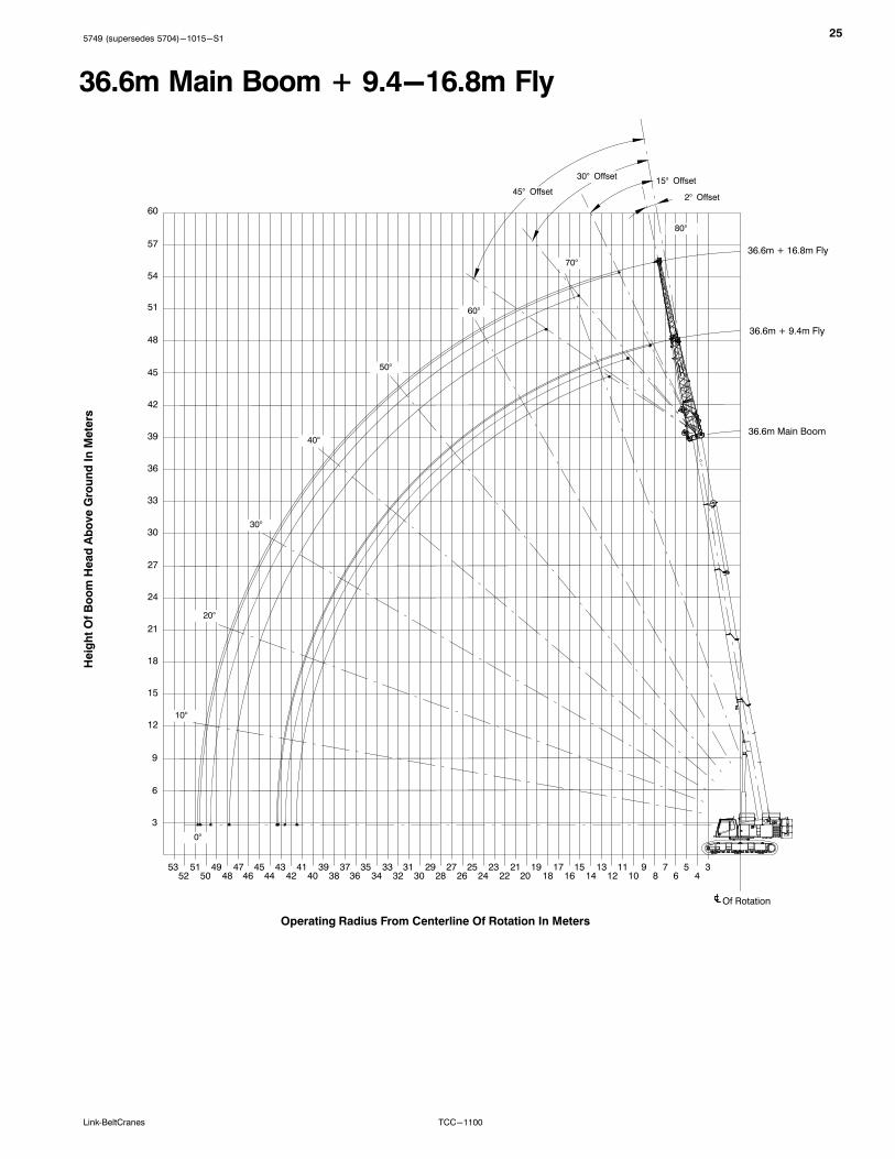
TCC-1100Link‐BeltCranes
36.6m Main Boom + 9.4-16.8m Fly
80°
70°
60°
50°
40°
30°
20°
10°
0°
Heig
ht
Of
Bo
om
Head
Ab
ove G
rou
nd
In
Mete
rs
Operating Radius From Centerline Of Rotation In Meters
45° Offset
30° Offset15° Offset
3
3
Of Rotation
36.6m Main Boom
2° Offset
9
12
15
18
21
24
27
30
33
36
39
42
45
48
51
54
57
60
6
36.6m + 9.4m Fly
36.6m + 16.8m Fly
5791113151719212325272931333537394143454749515346810121416182022242628303234363840424446485052

265749 (supersedes 5704)-1015-S1
TCC-1100 Link‐BeltCranes
45.72m Main Boom + 9.4-16.8m Fly
2° Offset
80°
70°
60°
50°
40°
30°
20°
10°
0°
Heig
ht
Of
Bo
om
Head
Ab
ove G
rou
nd
In
Mete
rs
Operating Radius From Centerline Of Rotation In Meters
45° Offset30° Offset
15° Offset
3
45.72m Main Boom
3
Of Rotation
5791113151719212325272931333537394143454749515355575946810121416202224262830323436384042444648 18505254565860
6
9
12
15
18
21
24
27
30
33
36
39
42
45
48
51
54
57
60
63
66
45.72m + 9.4m Fly
45.72m + 16.8m Fly
275749 (supersedes 5704)-1015-S1
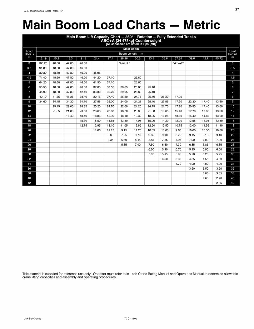
TCC-1100Link‐BeltCranes
Main Boom Load Charts - MetricMain Boom Lift Capacity Chart - 360� Rotation - Fully Extended Tracks
ABC+A [34 473kg] Counterweight[All capacities are listed in kips (mt)]
LoadRadius
m
Main BoomLoad
Radiusm
Boom Length - m
12.19 15.2 18.3 21.3 24.4 27.4 28.96 30.5 33.5 36.6 37.34 39.6 42.7 45.72
3 100.20 48.60 47.80 46.00 "Amax1" "Amax2" 3
3.5 91.80 48.60 47.80 46.00 3.5
4 80.30 48.60 47.80 46.00 45.95 4
4.5 71.40 48.60 47.80 46.00 44.20 37.10 25.60 4.5
5 64.20 48.60 47.80 46.00 41.50 37.10 25.60 5
6 53.50 48.60 47.80 46.00 37.05 33.55 29.85 25.60 25.40 6
7 45.90 48.60 47.80 42.40 33.30 30.25 29.05 25.60 25.40 7
8 40.10 41.65 41.35 38.40 30.15 27.40 26.30 24.75 25.40 26.30 17.20 8
9 34.60 34.45 34.30 34.10 27.55 25.00 24.00 24.25 25.40 23.55 17.20 22.30 17.40 13.60 9
10 29.15 29.00 28.85 25.20 24.70 22.00 24.25 24.75 21.70 17.20 20.55 17.40 13.60 10
12 21.85 21.80 23.50 23.65 23.00 18.70 23.00 21.30 18.65 15.40 17.70 17.00 13.60 12
14 18.40 18.40 18.85 18.95 16.10 18.30 18.35 16.25 13.50 15.40 14.85 13.60 14
16 15.30 15.50 15.65 13.50 14.95 15.00 14.30 12.00 13.55 13.05 12.50 16
18 12.75 12.95 13.10 11.05 12.85 12.50 12.50 10.75 12.00 11.55 11.10 18
20 11.00 11.15 9.15 11.25 10.65 10.60 9.65 10.60 10.30 10.00 20
22 9.60 7.65 9.70 9.65 9.10 8.75 9.15 9.15 9.10 22
24 8.35 6.40 8.45 8.55 7.85 7.95 7.90 7.90 7.90 24
26 5.35 7.40 7.50 6.80 7.30 6.85 6.85 6.85 26
28 6.60 5.90 6.70 5.95 5.95 6.00 28
30 5.85 5.15 5.95 5.20 5.20 5.25 30
32 4.50 5.30 4.55 4.55 4.60 32
34 4.70 4.00 4.00 4.00 34
36 3.50 3.50 3.50 36
38 3.05 3.05 38
40 2.65 2.70 40
42 2.35 42
This material is supplied for reference use only. Operator must refer to in-cab Crane Rating Manual and Operator's Manual to determine allowablecrane lifting capacities and assembly and operating procedures.

285749 (supersedes 5704)-1015-S1
TCC-1100 Link‐BeltCranes
Main Boom Lift Capacity Chart - 360� Rotation - Fully Extended TracksABC+A [34 473kg] Counterweight
[All capacities are listed in kips (mt)]
LoadRadius
m
Main Boom + 3.1m Manual Offset Fly (2 Offsets)Load
Radiusm
Boom Length - m
12.19 15.20 18.30 21.30 24.40 27.40 30.50 33.50 36.60 39.60 42.70 45.72
3 28.30 23.55 3
3.5 28.30 23.55 23.55 3.5
4 28.30 23.55 23.55 4
4.5 28.30 23.55 23.55 24.00 4.5
5 28.30 23.55 23.55 24.00 24.00 5
6 28.15 23.55 23.55 24.00 24.00 24.90 6
7 26.40 23.55 23.55 24.00 24.00 24.90 25.40 27.20 7
8 24.90 23.55 23.55 24.00 24.00 24.90 25.40 25.15 23.50 8
9 23.60 23.55 23.55 24.00 24.00 24.90 25.40 23.35 21.65 17.75 9
10 22.55 23.55 23.55 24.00 24.00 24.90 25.40 21.75 19.95 17.75 14.10 10.95 10
12 21.10 22.85 23.10 23.05 23.05 22.95 22.90 19.10 17.25 16.35 14.10 10.95 12
14 18.35 18.30 18.30 18.25 18.20 17.05 15.05 14.25 13.70 10.95 14
16 14.95 14.95 14.90 14.85 14.85 13.20 12.50 12.05 10.95 16
18 12.45 12.40 12.40 12.35 12.35 11.70 11.05 10.37 9.05 18
20 10.50 10.15 10.45 10.40 10.40 9.85 9.45 9.05 20
22 8.95 8.95 8.95 8.95 8.85 8.50 8.20 22
24 7.70 7.70 7.70 7.70 7.70 7.60 7.30 24
26 6.65 6.65 6.65 6.65 6.65 6.55 26
28 5.80 5.75 5.75 5.75 5.75 28
30 5.05 5.00 5.00 5.00 5.00 30
32 4.35 4.35 4.35 4.35 32
34 3.80 3.80 3.75 34
36 3.30 3.30 3.30 36
38 2.85 2.85 38
40 2.45 40
42 2.10 42
This material is supplied for reference use only. Operator must refer to in-cab Crane Rating Manual and Operator's Manual to determine allowablecrane lifting capacities and assembly and operating procedures.

295749 (supersedes 5704)-1015-S1
TCC-1100Link‐BeltCranes
Main Boom Lift Capacity Chart - 360� Rotation - Fully Extended TracksABC+A [34 473kg] Counterweight
[All capacities are listed in kips (mt)]
LoadRadius
m
Main Boom + 3.1m Manual Offset Fly (15° Offsets)Load
Radiusm
Boom Length - m
12.19 15.20 18.30 21.30 24.40 27.40 30.50 33.50 36.60 39.60 42.70 45.72
3 28.30 23.55 3
3.5 28.30 23.55 23.55 3.5
4 27.50 23.55 23.55 4
4.5 26.75 23.55 23.55 24.00 4.5
5 26.00 23.55 23.55 24.00 5
6 24.75 23.55 23.55 24.00 24.00 24.90 6
7 23.65 23.55 23.55 24.00 24.00 24.90 25.40 26.50 7
8 22.75 23.55 23.55 24.00 24.00 24.90 25.40 24.55 23.00 8
9 22.00 23.35 23.55 24.00 24.00 24.90 25.40 22.85 21.45 17.75 9
10 21.40 22.60 23.55 24.00 24.00 24.90 25.25 21.35 20.05 17.75 14.10 10.95 10
12 21.05 21.55 22.50 23.30 23.25 23.20 23.10 18.90 17.40 16.50 14.10 10.95 12
14 18.50 18.50 18.55 18.50 18.45 18.45 16.85 15.15 14.40 13.80 10.95 14
16 15.10 15.10 15.10 15.05 15.00 13.35 12.65 12.15 10.95 16
18 12.55 12.55 12.55 12.55 12.50 11.80 11.15 10.75 9.05 18
20 10.60 10.60 10.60 10.55 10.50 9.95 9.55 9.05 20
22 9.05 9.10 9.10 9.05 9.00 8.60 8.30 22
24 7.80 7.80 7.80 7.80 7.80 7.70 7.40 24
26 6.75 6.75 6.75 6.75 6.75 6.65 26
28 5.85 5.85 5.85 5.85 5.85 28
30 5.10 5.10 5.10 5.10 5.10 30
32 4.45 4.45 4.40 4.40 32
34 3.85 3.85 3.85 34
36 3.35 3.35 3.35 36
38 2.90 2.90 38
40 2.50 40
42 2.15 42
This material is supplied for reference use only. Operator must refer to in-cab Crane Rating Manual and Operator's Manual to determine allowablecrane lifting capacities and assembly and operating procedures.

305749 (supersedes 5704)-1015-S1
TCC-1100 Link‐BeltCranes
Main Boom Lift Capacity Chart - 360� Rotation - Fully Extended TracksABC+A [34 473kg] Counterweight
[All capacities are listed in kips (mt)]
LoadRadius
m
Main Boom + 3.1m Manual Offset Fly (30° Offsets)Load
Radiusm
Boom Length - m
12.19 15.20 18.30 21.30 24.40 27.40 30.50 33.50 36.60 39.60 42.70 45.72
3 24.90 23.55 3
3.5 24.40 23.55 23.55 3.5
4 23.90 23.55 23.55 4
4.5 23.45 23.55 23.55 24.00 4.5
5 23.05 23.55 23.55 24.00 5
6 22.35 23.05 23.55 23.90 23.90 23.85 6
7 21.80 22.45 23.55 23.35 23.45 23.40 23.35 7
8 21.35 21.95 23.00 22.85 23.00 23.00 22.95 22.75 8
9 21.05 21.55 22.50 22.40 22.60 22.65 22.60 22.45 21.10 17.75 9
10 20.95 21.25 22.05 22.05 22.25 22.30 22.30 21.00 19.80 17.75 14.10 10
12 20.95 20.90 21.70 21.40 21.60 21.70 21.75 18.65 17.55 16.60 14.10 10.95 12
14 18.60 21.15 18.75 18.70 18.70 18.65 16.70 15.35 14.55 14.10 10.95 14
16 18.70 15.25 15.30 15.25 15.25 15.05 13.50 12.80 12.30 10.95 16
18 12.65 12.70 12.70 12.70 12.65 11.95 11.35 10.90 9.05 18
20 10.70 10.70 10.70 10.70 10.65 10.10 9.70 9.05 20
22 9.15 9.20 9.20 9.20 9.10 8.75 8.40 22
24 7.85 7.90 7.90 7.90 7.90 7.85 7.55 24
26 6.80 6.80 6.85 6.85 6.85 6.75 26
28 5.90 5.90 5.95 5.95 5.95 28
30 5.15 5.15 5.15 5.15 30
32 4.50 4.50 4.50 4.50 32
34 3.90 3.90 3.90 34
36 3.40 3.40 36
38 2.95 2.95 38
40 2.50 40
This material is supplied for reference use only. Operator must refer to in-cab Crane Rating Manual and Operator's Manual to determine allowablecrane lifting capacities and assembly and operating procedures.

315749 (supersedes 5704)-1015-S1
TCC-1100Link‐BeltCranes
Main Boom Lift Capacity Chart - 360� Rotation - Fully Extended TracksABC+A [34 473kg] Counterweight
[All capacities are listed in kips (mt)]
LoadRadius
m
Main Boom + 3.1m Manual Offset Fly (45° Offsets)Load
Radiusm
Boom Length - m
12.19 15.20 18.30 21.30 24.40 27.40 30.50 33.50 36.60 39.60 42.70 45.72
3 3
3.5 22.15 3.5
4 21.85 22.15 4
4.5 21.65 21.90 22.10 4.5
5 21.45 21.75 21.90 5
6 21.15 21.40 21.60 21.70 21.65 21.55 6
7 20.95 21.15 21.30 21.40 21.40 21.35 21.20 7
8 20.90 20.95 21.10 21.20 21.20 21.10 21.00 20.85 8
9 20.90 20.90 20.95 21.00 21.00 20.95 20.00 20.70 20.20 9
10 20.90 20.90 20.85 20.90 20.85 20.80 85.00 20.55 19.65 17.85 10
12 20.90 20.85 20.75 20.65 20.60 20.70 18.55 17.45 16.55 14.15 11.05 12
14 18.85 18.80 18.80 20.50 16.65 15.55 14.75 14.10 11.05 14
16 15.35 15.40 15.40 18.80 15.00 1..635 12.95 12.50 11.05 16
18 12.80 12.80 15.40 12.80 12.10 11.50 11.05 10.65 18
20 10.80 12.80 10.80 10.80 10.20 9.80 9.20 20
22 10.80 9.30 9.30 9.20 8.85 8.55 22
24 9.25 7.95 8.00 8.00 7.95 7.65 24
26 6.90 6.90 6.90 6.85 26
28 6.00 6.00 6.00 28
30 5.20 5.20 30
32 4.55 32
This material is supplied for reference use only. Operator must refer to in-cab Crane Rating Manual and Operator's Manual to determine allowablecrane lifting capacities and assembly and operating procedures.

325749 (supersedes 5704)-1015-S1
TCC-1100 Link‐BeltCranes
Jib Attachment Load Charts - MetricMain Boom Lift Capacity Chart - 360� Rotation - Fully Extended Tracks
ABC+A [34 473kg] Counterweight
[All capacities are listed in kips (mt)]
Load Radiusm
36.6m Main Boom Length
Load Radiusm
9.4m Manual Offset Fly 16.8m Manual Offset Fly
2 15 30 45 2 15 30 45
10 13.10 6.25 10
12 12.30 9.25 5.95 12
14 11.60 8.85 7.60 5.70 14
16 10.95 8.50 7.40 6.70 5.45 4.65 16
18 10.35 8.20 7.20 6.55 5.20 4.50 18
20 9.10 7.90 7.00 6.45 5.00 4.30 3.75 20
22 8.70 7.65 6.85 6.40 4.80 4.15 3.65 3.35 22
24 8.05 7.40 6.70 6.35 4.60 4.05 3.60 3.30 24
26 7.05 7.20 6.55 6.30 4.45 3.90 3.50 3.25 26
28 6.15 6.40 6.45 6.30 4.25 3.80 3.40 3.20 28
30 5.40 5.60 5.80 5.95 4.10 3.70 3.35 3.15 30
32 5.75 4.95 5.10 5.20 3.95 3.60 3.30 3.15 32
34 4.20 4.35 4.50 4.55 3.85 3.50 3.25 3.15 34
36 3.70 3.85 3.95 3.70 3.40 3.20 3.15 36
38 3.25 3.35 3.45 3.60 3.35 3.20 3.15 38
40 2.85 2.95 3.00 3.25 3.30 3.15 3.15 40
42 2.50 2.55 2.90 3.05 3.15 3.15 42
44 2.55 2.70 2.80 44
46 2.25 2.40 2.45 46
48 2.00 2.10 48
This material is supplied for reference use only. Operator must refer to in-cab Crane Rating Manual and Operator's Manual to determine allowablecrane lifting capacities and assembly and operating procedures.

335749 (supersedes 5704)-1015-S1
TCC-1100Link‐BeltCranes
Main Boom Lift Capacity Chart - 360� Rotation - Fully Extended TracksABC+A [34 473kg] Counterweight
[All capacities are listed in kips (mt)]
Load Radiusm
45.72m Main Boom Length
Load Radiusm
9.4m Manual Offset Fly 16.8m Manual Offset Fly
2 15 30 45 2 15 30 45
12 7.35 3
14 7.35 7.35 4.55 3.5
16 7.35 7.35 6.65 4.40 4
18 7.35 7.20 6.55 6.10 4.30 3.85 4.5
20 7.35 7.10 6.45 6.05 4.20 3.75 5
22 7.35 6.95 6.35 6.00 4.10 3.65 3.30 6
24 6.90 6.80 6.25 5.95 4.00 3.60 3.25 7
26 6.20 6.40 6.15 5.90 3.90 3.50 3.20 3.00 8
28 5.60 5.75 5.95 5.90 3.85 3.45 3.15 2.95 9
30 5.00 5.20 5.35 5.55 3.75 3.35 3.10 2.95 10
32 4.50 4.70 4.85 4.95 3.65 3.30 3.50 2.90 12
34 4.00 4.20 4.35 4.50 3.60 3.25 3.00 2.90 14
36 3.50 3.70 3.85 3.95 3.50 3.20 3.00 2.90 16
38 3.10 3.25 3.35 3.45 3.15 3.15 2.95 2.90 18
40 2.70 2.80 2.95 3.00 2.85 3.00 2.95 2.90 20
42 2.35 2.45 2.55 2.60 2.55 2.70 2.85 2.90 22
44 2.00 2.10 2.20 2.25 2.40 2.55 2.70 24
46 1.75 1.80 1.85 2.00 2.15 2.30 2.35 26
48 1.45 1.55 1.55 1.75 1.90 2.00 2.10 28
50 1.25 1.30 1.50 1.65 1.75 1.80 30
52 1.05 1.05 1.30 1.40 1.50 32
54 1.10 1.20 1.25 34
56 0.90 0.95 1.00 36
58 0.75 0.75 38
This material is supplied for reference use only. Operator must refer to in-cab Crane Rating Manual and Operator's Manual to determine allowablecrane lifting capacities and assembly and operating procedures.

345749 (supersedes 5704)-1015-S1
TCC-1100 Link‐BeltCranes
This Page Intentionally Blank

355749 (supersedes 5704)-1015-S1
TCC-1100Link‐BeltCranes
This Page Intentionally Blank

5749 (supersedes 5704)-1015-S1
TCC-1100 Link‐Belt Cranes
Link-Belt Construction Equipment Company Lexington, Kentucky www.linkbelt.com�Link-Belt is a registered trademark. Copyright 2015. We are constantly improving our products and therefore reserve the right to change designs and specifications.