11. Theory of Atomic-ScaleFriction - Nanoten
24
11. Theory of Atomic-Scale Friction D. Tomimek Wllh 17 Figures Friction between two solids is not only one of the most common, but also one of the most complex and least understood processes in nature [11.1]. At rough interfaces, plastic deformations and abrasion - both associated with the re- arrangement of interatomic bonds - are responsible for energy dissipation during the relative motion of the two solids. A fundamentally different behavior is observed at "perfect", weakly-interacting interfaces. There, friction without wear corresponds to energy transfer from macroscopic degrees of freedom (describing the relative motion of the bodies in contact) to microscopic degrees of freedom (such as phonons or electronic excitations) which occur as heal. Considerable success has been achieved recently in the quantitative measure- ment of friction forces on the atomic scale [11.2J and the understanding of the underlying microscopic mechanisms in the case of sliding friction without wear [1l.3]. This success has been made possible by an increasing sophistication in the characterization of interfaces, from the use of rather rough interfaces [11.4,5] to atomically flat areas [11.6J, and imaginative adaptations of the Scanning Force Microscope (SFM) [1l.7J for friction measurements. On the other hand, rapid development of computational techniques and the availability of large computer resources have made quantitative predictions for the friction process possible [11.8, 9]. The success on both the experimental and theoretical side has opened up a new research field called Ilanorribology. In this chapter, I will discuss the new possibilities, but also the limitations of scanning force microscopy in obtaining fundamental understanding of both the slidillg and rolling Jricrioll processes. I will start with a brief discussion of the irreversibility in the friction process and possible ways to model an "ideal friction machine" based on the SFM. Next, I will review existing first-principles calculations for friction associated with a single atom sliding on a substrate. Finally, I will discuss limits of nondestructive adsorbate-substrate interactions which are related to the onset of \"'ear in SFM measurements, 11.1 Microscopic Origins of Friction Let us consider two bodies in contact, A and B, which are in relative motion, Under normal conditions, a friction force F f occurs in this situation along the direction of motion in addition to the reaction forces of classical mechanics Springer Series in Surface Scit:m:es, Vol. 19 Tunneling III Eds .. R, Wief>endanger ' H.·J. GU[J[herodt 1("Springer-Verlag Berlin Heidelberg 199J
Transcript of 11. Theory of Atomic-ScaleFriction - Nanoten

11. Theory of Atomic-Scale Friction
D. Tomimek
Wllh 17 Figures
Friction between two solids is not only one of the most common, but also one ofthe most complex and least understood processes in nature [11.1]. At roughinterfaces, plastic deformations and abrasion - both associated with the rearrangement of interatomic bonds - are responsible for energy dissipationduring the relative motion of the two solids. A fundamentally different behavioris observed at "perfect", weakly-interacting interfaces. There, friction withoutwear corresponds to energy transfer from macroscopic degrees of freedom(describing the relative motion of the bodies in contact) to microscopic degreesof freedom (such as phonons or electronic excitations) which occur as heal.Considerable success has been achieved recently in the quantitative measurement of friction forces on the atomic scale [11.2J and the understanding of theunderlying microscopic mechanisms in the case of sliding friction without wear[1l.3]. This success has been made possible by an increasing sophistication inthe characterization of interfaces, from the use of rather rough interfaces[11.4,5] to atomically flat areas [11.6J, and imaginative adaptations of theScanning Force Microscope (SFM) [1l.7J for friction measurements. On theother hand, rapid development of computational techniques and the availabilityof large computer resources have made quantitative predictions for the frictionprocess possible [11.8, 9]. The success on both the experimental and theoreticalside has opened up a new research field called Ilanorribology.
In this chapter, I will discuss the new possibilities, but also the limitations ofscanning force microscopy in obtaining fundamental understanding of both theslidillg and rolling Jricrioll processes. I will start with a brief discussion of theirreversibility in the friction process and possible ways to model an "idealfriction machine" based on the SFM. Next, I will review existing first-principlescalculations for friction associated with a single atom sliding on a substrate.Finally, I will discuss limits of nondestructive adsorbate-substrate interactionswhich are related to the onset of \"'ear in SFM measurements,
11.1 Microscopic Origins of Friction
Let us consider two bodies in contact, A and B, which are in relative motion,Under normal conditions, a friction force F f occurs in this situation along thedirection of motion in addition to the reaction forces of classical mechanics
Springer Series in Surface Scit:m:es, Vol. 19Scannin~ Tunneling Microscop~ III Eds.. R, Wief>endanger ' H.·J. GU[J[herodt1("Springer-Verlag Berlin Heidelberg 199J

270 D. Tomanek
[11.10]. This force is related to the applied load F,,, between the two bodies as
(11.1)
The coefficient of friction, 1', ranges typically between 10- 2 for smooth interfacesand 1 for rough interfaces. Large values of I' reflect the fact that interatomicbonds at the A-B interface are being broken or rearranged during the relativemotion of the bodies. At an interface with essentially flat areas, we can considerseveral cases which can be classified according to relative bond strengths. Thiswill allow us to establish the conditions under which friction without wear canbe expected.
Let us first discuss the basic situations occurring during friction with wear. Ifinteratomic A-A bonds are comparable in strength to B-B bonds, and bothmuch weaker than A-B bonds, the relative motion between A and B willeliminate large asperities at the interface in a "sandpaper action". This process istypically accompained by long-ranged plastic deformations and dislocationmotion away from the interface. Note that, in this case, a lubricant C is oftenused [11.11]. The situation of A-B bonds stronger than A-A and B-B bondswill lead to spontaneous bonding at the interface (similar to the case of strongC-C bonds which make C an adhesive). 'rhe relative motion of A and B will inthis case result from a fracture inside the weaker of the sol.ids along the interface.If B-B bonds are much weaker than A-A bonds, the relative motion of A onB will lead to a "plowing" of B by A.
Friction without wear can occur in the ideal case of a defect-free interfacebetween single crystals A and B. In order to avoid plastic deformations, we alsorequire the load Fen on the interface not to exceed the elastic limit within the"softer" solid. Furthermore, the A-A bonds should be comparable in strength toB-B bonds, and at the same time be stronger than A-B bonds. It was recognizeda long time ago that, in this case, the only source of friction and its modulationshould be atomic-scale corrugations of the A-B interaction potential [11.12].
These modulations and the associated friction force have first been observedsuccessfully on highly oriented pyrolytic graphite using the friction forcemicroscope (FFM) with a tungsten tip [11.2]. As for the theory, two differentapproaches have been used to determine atomic-scale friction. Moleculardynamics calculations with parametrized pair potentials have been used tosimulate the stick--..lip motion and to determine the friction force between a SiSFM tip and a Si substrate [11.8]. An independent approach, based on an abinitio density functional calculation, has been used to determine the trajectory ofa Pd atom moving along a graphite surface and to estimate the associatedfriction force [11.9].
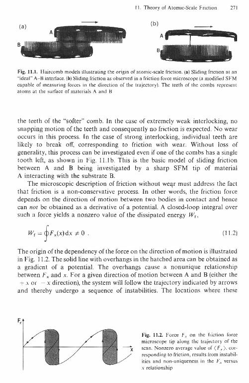
The variety of processes which are expected to occur during sliding frictioncan be easily illustrated in a somewhat simple-minded model, namely twohaircombs in relative motion, with their teeth (representing surface atoms) incontact. This is shown in Fig. 11.1. "Friction" occurs due to the snappingmotion as the teeth slide against each other (Fig. 11.1a). In the case that the teethare only weakly interlocked, friction energy is dissipated into the vibrations of
B
II. Theory of Atomic·Scalc Friction 271
(b)
.--Fig. 11.1. Haircomb models illustrating the origin of atomic-scale friction. (a) Sliding friction at an"ideal" A-B interface. (b) Sliding friction as observed in a friction force microscope (a modified SFMcapable of measuring forces in the direction of the trajectory). The teeth of !he combs represent310ms al lbe surface of materials A and B
the teeth of the "softer" comb. [n the case of extremely weak interlocking, nosnapping motion of the teeth and consequently no friction is expected. No wearoccurs in this process. In the case of strong interlocking, individual teeth arelikely to break off, corresponding to friction with wear. Without loss ofgenerality, this process can be investigated even if one of the combs has a singletooth left, as shown in Fig. 11.1 b. This is the basic model of sliding frictionbetween A and B being investigated by a sharp SFM tip of materialA interacting with the snbstrate B.
The microscopic description of friction without we~r must address the factthat friction is a non-conservative process. In other words, the friction forcedepends on the direction of motion between two bodies in contact and hencecan not be obtained as a derivative of a potential. A closed-loop integral oversuch a force yields a nonzero value of the dissipated energy W r ,
W, = TF.(X)dX oF 0 . (11.2)
The origin of the dependency oftheforce on the direction of motion is illustratedin Fig. 11.2. The solid line with overhangs in the hatched area can be obtained asa gradient of a potential. The overhangs cause a nonunique relationshipbetween F:x. and x. For a given direction of motion between A and B (either the+ x or - x direction), the system will follow the trajectory indicated by arrows
and thereby undergo a sequence of instabilities. The locations where these
F,
Fig. 1l~ Force Fx on the friction forcemicroscope tip along the trajectory of thescan. Nonzero average value of <L,>, corresponding to friction, results from instabil·ities and non-uniqueness in the f~ versusx relationship
272 D. Tomanek
instabilities (or "snapping") occur, depend on the direction of motion. Theresulting hysteresis reflects the microscopic irreversibility in the proness. Thedegrees offreedom predominantly involved in the instabilities are those of A orB which are easiest to excite, giving rise to "tip-induned" or "substrate-induned"friction. The energy dissipated in friction, Wr, is related to the hatched area inthe hysteresis curve. In the following, we will investigate the microscopic orgin ofthis hysteresis and discuss friction in a quantitative way.
11.2 Ideal Friction Machines
11.2.1 Sliding Friction
In order to describe friction in a given system better than phenomenologically,we must carefully examine the microscopic processes which lie at the origin ofthe hysteresis in the "forne versus position" curve in Fig. 11.2. I will start thediscussion with the sliding friction between an SFM tip and the substrate. Afterdescribing the real instrument which is being used to study atomic-scale friction,I will simplify this system to an idealized "Friction Force Microscope" (FFM)which gives rise to sliding friction without wear during a surface scan. I willdescribe two different models of the FFM which contain the essential physicsleading to friction and which I will call "ideal friction machines" [1l.I3]. Thesemodels should be sufficiently realistic to allow a comparison with theexperimental equipment described in the following.
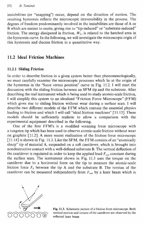
One of the first FFM's is a modified scanning forne microscope witha tungsten tip which has been used to observe atomic-scale friction without wearon graphite [11.2]. A more recent realization of the friction forne microscopc[1l.I4] is shown in Fig. 11.3. Like the SFM, the FFM consists of an "atomicallysharp" tip of material A, suspended on a soft cantilever, which is brought intonondestructive contact with a well-defined substrate B. The vertical deflection ofthe cantilever is regulated in order to keep the applied load F,,, constant duringthe surface scan. The instrument shown in Fig. 11.3 uses the torque on thecantilever due to a horizontal forne on the tip to measure the atomic-scalefriction force F, between the tip A and the substrate B. The torsion of thecantilever can be measured independently from F,,, by a laser beam which is
, I" I
(~~
rag. 11.3. Schematic picture or a friction force microscope. Bothvertical molion and torsion ofthe cantilever are observed by thereflected laser beam

(a)
"!M _v-az ,_z, ~...
a " 4f "",
(b)
J l. Theory of Atomic·Scale Friction 273
Fig. 11.4. Two models of the Friction Force Microscope (FFM). In both models. the externalsuspension M is guided aJong the horizontal surface x direction at a constant velocityv = dXw/dr - O. The load F"-"Ion the "sharp" tip (indicated by VI is kept constant along thetrajectory z,(x,) (shown by arrows~ (a) A "maximum friction microscope", where the tip is free tomove up, but gets stuck. at the maximum z, between tu/2 and lU.. (b) A "realistic frictionmicroscope". where the position of the tip x, and the suspension x'" may differ. In this case, thefriction force Fr is related to the elongation X, - XM of the horizontal spring from its equilibriumvalue [11.13]
reflected from the cantilever. This experiment gives direct information about Fras a function of F,x<. It is interesting to note that the torque induced by thehorizontal force can increase the vertical tip deflection at topographic surfacefeatures and hence enhance the contrast of the SFM image.
Two idealized models of a friction force microscope are shown in Fig. /1.4.In both models, the microscope suspension M moves quasi-staticalIy along thesurface x-direction with its position XM as the externally-controUed parameter.The tip is assumed to be stiff in respect to excursions in the surface y-direction.We restrict our discussion to the case of tip-induced friction and assume a rigidsubstrate which applies for friction measurements on graphite [11.2, 9].
In the "maximum-friction microscope" [11.9], the fulI amount of energyneeded to cross the potential energy barrier AV along Ax is dissipated into heat[11.15]. This process and the corresponding friction force can be observed in animperfect scanning force microscope which is shown in Fig. 11.4a. A verticalspring connects the tip and the external microscope suspension M. The horizontal positions of the tip and the suspension are rigidly coupled, x, = XM = x. Foro< x < tJ.X/2, the load F", on the tip is kept constant by moving the suspensionup or down. For Axl2 < x < ax, however, the tip gets stuck at the maximumvalue of Z,. At Ax, the energy AV stored in the spring is abruptly and completelyreleased into internal degrees of freedom which appear as heat.
The potential energy V(x) during the sliding process is shown in Fig. I J.5a[11.9]. Theforce on the tip in the negative x-direction, as defined in Fig. llAa, isgiven by
if 0 < XM < Axl2if Axl2 < XM < Ax
(11.3)

274 D. Tomanek
-1.5 '--------'--+--~___;f-----'----'
a 4f
,,,,
1.5~b) ..1.0(Fl)
0.5 ----- -.-------.
0.0 /-------';-0---;__-------1
r..; -0.5
-1.0
(a)
0.6
0.6 r----,--~--___r_-_,
x x
Fig.ll.5. (a) Potential energy of the tip Vex). (b) the friction force F,(x) and the average friction force(Fr>in (he "maximum friction ~ microscope. The arrows indicate the tip trajectory corresponding toa relaxed vertical tip position Z,.mJo for a constant load on the tip [11.13J
and shown in Fig_ 11.5b. The non-zero value of the average friction force (Ff ),
indicated by the dash-dotted line in Fig. 11.5b, is a consequence of the mechanism which allows the tip to get stuck. Ff(xM) is a non-conservative force since itdoes depend on the scan direction_ In absence of the "sticking" mechanism, F(would be given by the gradient of the potential energy everywhere, as indicated by the dashed line in Fig. 11.5b; it would be independent of the scan direction and hence conservative. In such a case, Fr would inhibit sliding foro< XM < fu/2 and promote sliding for ilxl2 < XM < .1x. The average value ofthis force would be zero, resulting in no friction.
A more realistic construction of the friction force microscope is shown inFig. llAb. In this "realisticfriction microscope", the SFM-like tip-spring assembly is elastically coupled to the suspension in the horizontal direction, so that thehorizontal tip position Xt may differ from XM' While the equilibrium height of thetip, Zt. min (Xt), is independent of the scan direction in this model, a "snappingmotion" leading to friction can still occur in this instrument, specifically in thecase of a soft horizontal spring and a strongly corrugated tip-substrate poteotial. In the following, I will discuss the conditions for the onset of friction in thismodel more quantitatively_
For a given Xl> the SFM tip experiences a potential V(x" Zt) = Vint(x" Zt) +Fe" Zt consisting of the tip-surface interaction V1nt and the work against F e..
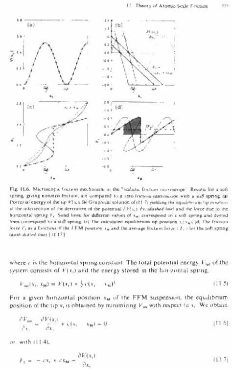
The tip trajectory Zt. min (oX,) during the surface scan is given by the minimum ofV(x e• Zl) with respect to Zt. For this trajectory, V(x,) = V(x l , Zt. miD} represents aneffective tip-substrate potential. This potential V(x,) depends strongly onFm and is corrugated with the periodicity of the substrate due to variations ofthe chemical bond strength and of Zt, min, as shown in Fig. 11.6a. The corrugation of the potential V(xt ) will elongate or compress the horizontal spring fromits equilibrium which corresponds to Xl = XM- The "instantaneous friction force"is given by
(1 1.4)
""'4-.; c--·. I,•
~. ~I_. 'M~
"~--,rtbi"•.......
•,.1•",...• \,'f--'.:i'
..
r-;;;;---":'--_. "
..' .......,-" \,•••
no. 11.6. Mo'"""""," f,,,,.,,, _~." .... '" "'" I.o<~ J.>u_ ,.....,_" ~"'"..,. .....'pm...""1 ......'a f"."",". Ol. """'ro<l'«l ,,, " '''''''" ~"•• ouII _ I_I1'01<.,..1'''''1101 "'" t.p VI ~l f'\(l<o""'" "",,, "'(1 ,1,_,,- '_ top ..~,_., "......,_~ 01 ,!'It ' .. _uaJ U(...l"~""''''''''''''j ,.. lorno""",'o ""_,oj 'P'V'.I, SoloIl_ _.'_d,•.__ ." _ ..... <io<1O<l
I_,,~""-'"' ~"_"Il"'_""",_",,_ ~',.,(~TMr,,,,,,,,,,_ r, .. • ~"."....~ ,.. fr~ .-..... ' • ..,.l ,.......,... _ iI>rI:< CI, >10< ,II< >OIl _"JI.... "'.........,(IIIIJ
.. here c" ,lie hOm""'kl """n~ """"aM The 'otal p<,>,"llli.1 cnc'lY V... of lhe1~'l.m OIl~.ml' 0/ 11«,) a"d Ihe enuiS liMed In {I!c hon1.lmIJllpnnJ,
(lUI
F(lr ~ i'~~n h"ri~... n'.l I""""'" <.. or ,hi: FfM ""'1"'''''''''' II>< equilibnumPO,ili!)n (If the: lOp ,Y, 'I o\>l.'1\<ld b~ TII,rum,-on, II... ""h 'Upa.110" W<obulln
". JVI~,I• «A, ,,,] _ 0
1"•• - a.,m, ..."h III..l
" . Jill.·,1~" co.. • ",
(II ~)
(II 7)

276 D. Tomanek
A graphical solution of (11.7) is shown in Fig. 11.6b and the resulting relationX,(XM) is shown in Fig. 11.6c.
If, for a stiff spring, the force constant c exceeds the critical valueCeri' = - [a2 V(x,)/ax,2]rnin, we obtain a single solution X, for all XM. Thissituation is indicated by the dotted line in Figs. 11.6b, c. The friction force Fr isgiven by (11.4) and shown by the dotted line in Fig. 11.6d. Since Fr is independent of the scan direction, it is conservative, resulting in (Fr) = O. Consequently, we expect no friction to occur during a nondestructive surface scan ina standard SFM which we can consider as a limiting case of the instrumentshown in Fig. 11.4b for c --+ co .
A more interesting case arises if the horizontal spring is soft, c < Ceri!' Thissituation is represented by the solid line in Figs. 11.6b, c. In this case, thesolution X,(XM) of (11.7) displays a sequence of instabilities. These instabilitieslead to a stick-slip motion of the tip as XM increases, similar to "pluckinga string". The hysteresis in the X,(XM) relation (Fig. 1l.6c) results in a dependenceof the force Fr on the scan directioo. The friction force Fr(XM) in this case isshown by the solid line in Fig. l1.6d. It is a nonconservative/dissipative forceand averages to a non-zero value of (Fr), given by the dash-dotted line. Theenergy released from the elongated spring into heat is represented by the shadedarea in Fig. 11.6d.
The present theory predicts occurrence of friction only for very soft springsor a strongly corrugated potential Vex,). The latter fact can be verified experimentally since the corrugations,1 Vex,) increase strongly with increasing appliedload [11.9]. Consequently, for a given c, the friction force is zero unlessa minimum load F ex! is exceeded. On the other hand, for given Fox" no frictioncan occur if c exceeds the critical value cerit(F~l)'
A similar situation occurs during sliding between large commensurate flatsurfaces of A on B. In that case, c is given by the elastic constants of A at theinterface [11.12], hence can not be changed independently. Since c is rather largein many materials, zero friction should be observed for moderate applied loadsin the absence of wear and plastic deformations. For a multi-atom "tip" which iscommensurate with the substrate, the tip-substrate potential is proportional tothe number of tip atoms at the interface, n, as is the critical value Cerll for nonzerofriction. In this case, the effective FFM spring depends both on the externalspring and the elastic response of the tip material. The inverse value of Ceri' isgiven by the sum of the inverse values of the corresponding spring constants.For a large tip which is incommensurate with the substrate, no friction shouldoccur [11.3].
The average friction force <Fe> as a function of the load F ex1 and the forceconstant C is shown as a contour plot in Fig. 11.7. Clearly, the applicable loadrange is limited by the underlying assumption of contact without wear. Thisfigure illustrates that not only the friction force Fe, but also the friction coefficient J.l = (Fr)/Fox" depend strongly both on the interaction potential betweenthe two materials in contact and on the intrinsic force constant c of the frictionforce microscope. This clearly makes the friction force dependent on the

---,, ,.•• ,.,0
•
'-.. ,1.1. r_, pIoo 0( "" '''''11< 10...,_-.. {I,> ...~... '" IW ,-"_.,, 'NIota.~I' T"Ooa.bLo l<v._._0: lot • 1>1.. "'- _, ,~ ,I,... ,"pM<."Tho_ "'*"- '- ..__ b7 UlI _ <If "" ..- ..
-..cl "'... Ilo< ... boO (II IJJ
OOnOlru<1l{)o P'Uamclers of ,he FFM There IS also O!>C aoJ ~nl.~ 111 ,h..w:, c """ be eho""" III luch. way lhal 0<1II_''''ru f1><.1"", ,""' e ...co ~l ...... '1Io..d, f ...
11.1.2 Rolli.. Frktltl"
We h....e ..en Ih", lbd'''t fnchon " rdn,ed 10 • h~"cl'eSII ,n 'he o,l''';rellll;)l,\t"p dcpw;led 111 ~"I- ll.oc "'S J w,U oi,........ III .he 1oUo...~oc. tolli.,l
{"."un II rcr.'ed III • hy.,.r.... ,n .be :'(1..) rd.'lOGIIl,p 00.:'''''''1 dO""1...n.:.1 bl'prc>lch "'.11 SFM hp to, .urt.ce.. The o.H,c::op>ndu>SlIII.ubil,'yh... bncny bun d'Ku~ In Olap<l:' 4 IV{>lum< I, pall"" 10lllf) and .. ,U""tn.,c<I
,., , T --'M
I. ",I» • ~ ., ~U
ir-_"V(.,},,' ..-
(.;1 ........ 10> Sc_ oJ • """____ t'!r_ ,.. ,.. -.._,..-""- --........., ....-.".......""'_ '''tf: $ _",, __ < ••• _ _. I _,~....__....-- ...... -Ill'""""' .......__<Jdt

278 D. Tomanek
in Fig. 11.8. The cantilever can be conveniently represented by a vertical springwith a force constant c (Fig. 1L8a). The substrate-induced force on the tip Ft iscompensated by the elongated spring,
(11.8)
Here, ZM is the equilibrium tip position in the absence of the substrate. The totalpotential energy V,o, of the system consists of the tip-substrate interactionV(z, - zs) = V(z,) (note that the topmost substrate layer is at Zs = 0) and theenergy stored in the verti.cal spring,
(11.9)
For a given position ZM of the tip suspension, the equilibrium position of the tipz, is obtained by minimizing VIOl with respect to Z,. We obtain
(11.1 0)
or, with (11.8),
(11.11)
A graphical solution of (11.11) is exhibited in Fig. l1.8b and the resultingrelation Z,(ZM) is di.splayed in Fig. 11.8c.
Let us consider a tip approaching the substrate from z ...... 00 . The force onthe tip F, will be zero first, resulting in z, = Z/.t> as shown in Fig. 11.8b, c. As thetip slowly approaches the point labeled"1", a deflection towards the surfaceoccurs due to the attractive tip-substrate interaction. At the point labeled" J",the spring can no longer compensate the strong tip-substrate attraction, and thetip jumps to a point labeled "2". The resulting kinetic energy of the tip isdissipated into heat or plastic deformations at the tip-substrate interface.Should the microscope suspension ZM approach the substrate further, the tip willfirst experience a weakly attractive, then a repulsive interaction with thesubstrate and will undergo no instabilities. Upon retracting the microscopesuspension 2M, the tip will first probe the strongly attractive part of the potentialbetween points "2" and "3". At point "3", the force in the stretched spring can nolonger be compensated by the tip-substrate attraction, and the tip jumps to thepoint labeled by "4". Upon further retracting the microscope suspension ZM, thetip will experience a decreasing attractive interaction from the substrate,resulting in 2, .... ZM with no further instabilities. This is quite analogous to theresults presented in Fig. 4.6 for the case of a stationary tip suspension ZM anda moving sample.
Since according to (11.8), F, = - c(Zt - ZM) is the force on the tip, thehatched area in Fig. H.8c is proportional to the energy dissipated during an

Ca)
(b)
(cJ
(
/11 III}})JJ} 11 Il)}}ABC
II. Theory of Atomic~ScaleFriction 279
Fig. 11.9. Approach-retraction cycle of (a) a single SFM tip and(b) an array of lips attached to a cylinder rolling on a substrate,The relalion of these models to rolling friction between a solidcylinder and a substrate. shown in (c), is discussed in the lext
approach-retraction cycle of an SFM tip. This A-B-<::-A cycle, which is illustrated in Fig. l1.9a for a single SFM tip, occurs during a revolution by tJ.4> ofa rolling cylinder which has a set of SFM tips attached to the surface, as shownin Fig. l1.9b. The latter is, as a matter of fact, a reasonahle model for the energydissipation at the surface of a solid cylioder, once we associate SFM tips withsurface atoms. The corresponding cylinder, which can be imagined as coveredby sticky tape and rolling on a substrate, is shown in Fig. 11.9c. The analogybetween the cylinder and the SFM is based on the fact that the surface layer ofthe cylinder interacts with the substrate by Lennard-Jones type potentials, andis kept in place by barmonic forces, same as the SFM tip in Fig. 11.8a.
We conclude that the microscopic origin of rolling friction without wear liesin the hysteresis in the z,(z.,) relation in Fig. 11.8c. Consequently, the microscopic mechanism which transfers macroscopic rotational energy from the cylinder into microscopic degrees of freedom (heat) can be studied quantitativelyby measuring the energy dissipated during a single approach-retraction cycle ofan SFM tip.
11.3 Predictive Calculations of tbe Friction Force
11.3.1 Tip-Substrate Interactions in Realistic Systems: Pd on Graphite
As I discussed above, a quantitative study of sliding or rolling friction is possible,once the interaction potential Vat the interface between material A and material

280 D. Tomimek
B is known accurately enough. In this section, I want to illustrate how fora model system, namely a Pd FFM tip interacting with a graphite substrate, thisinteraction can be calculated from first principles.
Graphite is an ideal substrate for the study of friction since the bindingenergy of adsorbed atoms and the variations thereof along the surface arenegligibly small near the equilibrium adsorbate-substrate separation. This isspecifically true for the Pd-graphite interaction, which is depicted in Fig. 11.10afor the on-top (T) and the sixfold hollow (H) site as a function of the Pd-graphiteseparation [11.9]. The adsorption energies Ead of Pd atoms (representing thePd monolayer) in the two adsorption sites on graphite have been defined asE. d = Etolal(Pd/graphite) - Etola1(Pd) - EtoIOl(graphite). The first-principles totalenergy calculations for this system have been performed using the DensityFunctional Formalism within the Local Density Approximation (LDA) [11.17]and the ab initio pseudopotentiallocal orbital method [11.18]. The details of thecalculation have been discussed in [11.9]. The surface of hexagonal graphite hasbeen represented by a 4-layer slab and the adsorbate by a monolayer of Pdatoms in registry with tbe substrate (1 Pd atom per surface Wigner-Seitz cell ofgraphite). The valence charge density of the system is shown in Fig. ILl Ob.
For a realistically large and sharp SFM tip, the tip-substrate interaction islikely to be modified by the long-range van der Waals force which is notreproduced correctly by LDA. The van der Waals force between an extendedconical tip and a flat surface is estimated using the expression
(a)10
9
\l~a7
I • •I H HI
s:- a ~ 0.6
Ql ~ ~'-' ~o.o~ 4 .
Ilil ,2..0 ali 3.03 ••
2,
"0
-11.0 1.5 z.o 2.5 3.0 3.5
z(A)
(b)
Fig. 11.10. (a) Pd adsorption energy EOd as a function of the adsorption height z above the surfaceof hexagonal graphite. The solid lines connectingthe data points given by • are for the sixfoldhollow (H) siles, and the dashed liDes connectingthe data points given by • are for the on-top (T)sites. An enlarged section of the graph near equilibrium adsorption is shown in Ihe inse!. A secondinset shows the adsorption geometry and a pos·sible trajectory of the Pd layer along x in top view.(b) Valence charge density of the Pd/graphite system. The results of the LDA calculation are forthe on-top adsorption site near the equilibriumadsorption distance z"', and are shown in thexz-plane perpendicular to the surface. The ralioof two consecutive charge density contourse{n + 1)/!?(n) is 1.2 [11.9. 16)

11. Theory of Atomic-Scale Frictjon 281
F v,w(z) = All Xtan' a.j(6z), where a. is half the opening angle of the tip cone[11.19]. In this expression, All is the Hamaker constant and z is the distancebetween the conical tip and the surface. As typical values for a metal tip, one canassume a. = 30° and Au = 3 X 10- 19 1. For tip-substrate distances z > 3 A, thevan der Waals forces are very small, typically F v,w < to-' o N. At smallerdistances, these forces can be neglected when compared to the closed-shell andinternuclear repulsion which are both described correctly within LDA. Sinceeach of these regions is dominated by only one type of interaction, the totaltip-substrate force F m can be approximated as a superposition of the forcedescribed by LDA and the van der Waals force. It turns out that the van derWaals forces are not very important for the interpretation of experimentalresults, since they do not show atomic resolution [11.20] and are easilycompensated in the experiment by adjusting the force on the cantilever whichsupports the tip.
From Fig. 11.10a we see that the equilibrium adsorption bond strength ofS; 0.1 eV is very weak and much smaller than the cohesive energy of the tip
material (Pd metal) or the graphite substrate, which is an important prerequisitefor friction with no wear. Near the equilibrium adsorption height z '" 3 A,the corrugation of the graphite charge density is negligibly small due toSmoluchowski smoothing [11.21] and the position-dependence of theadsorption bond strength is ~ 0.1 eV [11.22], which should result in a verysmall friction coefficient. This calculation indicates that at bond lengths z :s; 2 A,the hollow site is favored with respect to the on-top site. At z '" 2 A, theadsorption energies are nearly the same and, at larger distances, it is the on-topsite which is slightly favored by < 0.05 eV. This is consistent with the dominantinteraction changing from closed-shell repulsion (which strongly favors thehollow site at very small adsorption bond lengths) to a weak chemisorptionbond (which is stabilized by the hybridization with p, orbitals in the on-top site).As I will discuss later, the change of the preferential adsorption site from theon-top to the hollow site as a function of the applied load leads to an anomaly inthe friction coefficient 1'_
A prerequisite for the calculation of the friction force is the preciseknowledge of the Pd adsorption energy E.,(x, z) along the whole graphitesurface. Since the corresponding "b initio calculations are computationally veryexpensive, it is useful to find simpler ways to determine this quantity. Severalsimple potentials have been used for this purpose so far [11.23-25]. Since smallinaccuracies in the interaction potentials have a large effect on the friction force,a safer way is to parametrize existing LOA results in a way which makes anevaluation of E., very easy everywhere. This can be achieved by approximatingE., by a local function which depends only on the total charge density of thegraphite host at the Pd adsorption site [11.26],
E.,(r) = E.,(Q(r)) . (11.12)
This form c~ the interaction potential is inspired by the density functionalformalism [11.17] and the embedded atom method [11.27] and hence is

282 D. Tomanek
50 .---,-~~~--r---r----,--~~-'--'
45
40
35
SO
25
20
15
\0
5
01------=------...,_ 5 '---'----L..----'_.L---'---'-_~_'__...J
1 2 3 4 5 6 7 B 9 10
fig. 11.11. Relation between the Pd adsorptionenergy Ew(r) and the total charge density ofgraphite err) at the adsorption site r. given by(11.13). An enlarged section of the graph nearequilibrium adsorption is given in the inset[11.26]
expected to be quite general, not restricted to the Pd-graphite system.A convenient parametrization of Ead(g(r» is
(11.13)
In the case of Pd on graphite, e\ = 343.076 eV, 1;2 = 2.1554 eV, (Xl = 1.245,(X2 = 0.41806, and go = l.OejA3. The dependence of E.d on g, obtained usingthe parametrized fonn in (11.13), is depicted in Fig. 11.1l.
In many cases, the total charge density can be well approximated bya supeIJlosition of atomic charge densities,
(11.14)n
This parametrization is especially convenient in case of deformed surfaces wherean LOA calculation is difficult due to reduced symmetry. On flat graphite
10
B
~ 6'"I0<
Q)4"-
3.s 2I
0
- 2 '--~_--'-----''------'-_-'---J'---...J
0.0 0.5 1.0 1.5 2.0 2.5 3.0 3.5
r(.K)
Fig. 11.l2. Radial plot of the charge density ofa carbon alom (;l.,(r), based on LDA (dashedline). The solid line shows the parametrized fonnof the charge density, given by (11.\5) [11.26]

surfaces, the maximum difference between the LOA charge density and thesuperposition of atomic charge densities is only a few percent.
Finally, the LOA cbarge density of the substrate (carbon) atnms can beconveniently expressed as
Q,,(r) = Qce-~' , (11.15)
where Qc = 6.0735 elA3 and p = 3.459 A- '. As shown in Fig. 11.12, this fitrepresents the LOA results very well.
113.2 Atnmic-Scale Friction in Realistic Systems: Pd on Grapbite
In the following, I will discuss the atomic-scale friction between a monatomicPd FFM tip and graphite, based on the "maximum friction microscope" modelillustrated in Fig. J 1.4a. I will sbow how the interaction potential between a Pdmonolayer and graphite (Pd in registry with the substrate), which has been givenin Sect. J 1.3.1, can be used to estimate tbe friction force (and frictinn cnefficientIl) as a function of the applied load.
For a microscopic understanding of the friction process, let us first considerthe motion of the Pd layer along tbe graphite surface, under tbe influence of anexternal load per atom [11.28] J,,, which is normal to the surface. Following[11.9], we consider a straight trajectory along tbe surface x direction connectingnearest neigbbor sixfold hollow sites on grapbite, whicb are separated by Llx andconnected by a bridge site.
As mentioned in the description of the "maximum friction microscope" inSect. 11.2.1 and shown in Fig. 11.4a, the horizontal positions of the tip and themicroscope suspension are the same, x, = XM = x. The potential energy V of thesystem along this trajectory has two main components. The first consists ofvariations of the tip-surface interaction (or adsorption bond energy)Vin,(x, z,) = E•• (x, z,). The second is given by the work against the external load
f." applied on tbe apex atom of the tip, due to the variations of the tip-substratedistance (or adsorption bond length). Hence,
(11.16)
Here, the potential energy has been set tn zero at the hollow site by defining
(11.17)
The equilibrium tip height z.. m;n(x) alnng the trajectory can be determined from
(11.18)
In Fig. J 1.I3a, V(x) is shown fnr different external loads. We find that tbevariations of V are dominated by tbe mechanical component and only partlycompensated by the site-dependence of the adsorption energy. As a result of the

284 D. Tomanek
(a) 0.6 r--~-~-~-~--,
0.5
....... 0.4
~~ 0.3
l<::; 0.2
0.1
f Pd~oQ ° 00 " "'0"
z{C) f~J 0i B H B H
Fig. 11.13. (a) Potential energy Vex) of the Pdgraphile system as a function of the position of thePd layer along the surface x-directioo., for externalforces J... = 3 X 10- 9 N (dotted line), 6 x 10- 9 N(dashed line) and 9 x 10 - 9 N (solid line). The insetshows the adsorption geometry and trajectory ofthe Pd layer in side view. (b) Atomic-scale structure of the force along the surface Ix (dashed line)and the friction force fr = max Un 0) (solid line) forIu, = 9 x 1O- 9 N [11.9)
H B H B
2.5
x(A)5.0
(b) 0.3 r--"--""---~-~---,
0.2
Z 0.1
~ 0.0 f---I----',.--f---':,-----i
~ -0.1 \ / \\ \, I"H ,I ' ~
....... -0.2 \ ...' H B \_/ H B\_,
5.02.5
x(X)
-0.3 L-_-'--_--'-_----L._~_----.J
0.0
variations of V along x, there is a position-dependent force fx along thex direction: In analogy to (11.3), this force is given by
(11.19)
and shown in Fig. 11.13b. The maximum value off", describes the static frictiongoverning the onset of stick-slip motion. Non-zero average sliding frictioncomes from the nonconservative "sticking mechanism" of this particular FFM,which is illustrated in Fig. l1.4a and which results in zero horizontal force onthe tip for Ax/2 < x < Ax (see (11.3)). In order to estimate the friction forcealong the trajectory, we note that the energy loss doe to friction W f along Ax cannot exceed the activation energy corresponding to the largest change of V, hence
(11.20)
Let us now assume that at Ax, the entire eoergy stored in the spring getstransferred into surface phonons and electron-hole pairs [11.15], as indicated inFig. 11.4a. Then, both sides of (11.20) will be equal. The horizontal force on thetip will show atomic-scale structure aod will oot average to zero, as indicated inFigs. ll.5b and 11.13b. This has beeo observed recently using the FFM [11.2].

11. Theory of Atomic-Scale Friction 285
The energy Wr dissipated in friction along the trajectory Ax can be used todefine the average friction force (f{) as
Wr = <f{) Ax ,
or, using (11.20) for Wr,
(11.21 )
(11.22)
The friction coefficient fJ., defined in (11.1), can now be estimated as
<f{) AVmaxfJ.=-=--.
fext fext 6.x(11.23)
In Fig. 11.14, fJ. is shown as a function of!.xr' We find a general increase of fJ. withincreasing external force, in contradiction to the general notion that fJ. is nearlyindependent of the load. The minimum in fJ.(fcxt) nearfext = 5 x 10- 9 N is causedby the switching of the minima in V(x) from H to B, depicted in Fig. 1I.l3a[11.29].
The above estimates of}l have been obtained for an infinitely rigid SUbstrate,an assumption which holds only within a limited load range. Theoretical resultsof [11.16, 30J, which will be summarized in Sect. 11.4, indicate that if theexternal force (per atom) exceeds 10- 8 N, the graphite surface is very stronglydeformed [11.31] and likely to be ruptured [11.6]. Since no plastic deformationshave been observed in the SFMjFFM studies [11.2], the applied forces wereprobably in the region!ext < 10- 8 N. For these values of!ew the above resultsfor the friction coefficient of f1 ~ 10 - 2 agree with the experimental value[11.2,6].
In order to obtain a meaningful comparison with observable friction forces,we have to make further assumptions about tbe macroscopic tip-substrate
Fig. 11.]4. Microscopic friction coefficient /l asa function of the external force per atomjut [11.9J
0.06
::t.... 0.05~II)
'0 0.04;;::-II)0
0.03U~0
0.02:lCol;e 0.01
5 10 15 20 25 30
fct (lO-II N)

286 D. Tomanek
interface and the elastic response of the substrate to external forces. In thesimplest case, we consider an atomically flat interface, where n atoms are incontact with the substrate, and neglect elastic deformations. Then, the externalforce per atom Jet! is related to the total external force Fexl by
leXl = *Fe... (11.24)
In Fig. 11.15 we use the calculated J1.(!eXI) to plot the total friction force Fr forsuch a perfectly flat interface consisting of 1500 Pd atoms. Since J1. increases withincreasing value ofIe", the Fr versus F exl relationship is non-linear, which hasalso been observed in the SFM experiment [11.2].
At this point, it is important to address the validity range of the abovecalculations. Obviously, the implicit assumption of an infinitely rigid substratewill remain realistic only for limited loads Fexl applied on the tip, especially inthe case of graphite. Also, there is a critical load for each system which marks theonset of plastic deformations within either the substrate or the tip. The latterpoint will be discussed in more detail in the following section. Here, I would liketo discuss a simpIe modification of the above results for friction in the case of anextended tip and an elastic substrate.
In the case of large external forces and an elastic substrate such as graphite,linear elasticity theory predicts [l1.32J the substrate deformations to beproportional to F ~!}. In the case of a spherical tip [l1.2J, the tip-substrateinterface area and the corresponding number of atoms in contact at the interfaceare proportional to F ;1,3 Then, the force per atom lext is proportional to F ;;,3.Hence for increasing external forces, variations of the effective force per atomand of J1. are strongly reduced due to the increasing interface area. This isillustrated by the dashed line in Fig. 11.15, which is based on the assumptionthat n = 1500 tip atoms are in contact with the substrate at F ex.' = 10- 6 N.These results are in good agreement with the FFM results for a large nonspecifictungsten tip with a radius R = 1500..\-3000..\ on graphite [11.2J, but show
Fig. 11.15. Macroscopic friction force Fr as a function of the external force Fe," fDr a large object. Thesolid line describes a "flat" object, the surface ofwhich consists of 1500 atums in contact with a rigidsubstrate. The dashed line describes a large spherical tip and also considers the effect of elastic substrate defonnations on the effective contact area.The dolted line corresponds to a constant frictioncoefficient J.l = 0.012 [11.9]
2015
t'1
,iJ"I"",• 1
.' I. ,I
II,,
I..
105
20
15
Z.,10 10.........,~
1%..-.....,5
00

1r. Theory of Alomic-Scale friction 287
a slightly larger increase of the friction force than that observed for the range ofexternal forces investigated.
It is instructive to discuss some consequences of the above theory foratomic-scale friction. At rough interfaces, the friction coefficient )1. generallyincreases due to the onset of plastic deformations or wear associated with bondbreaking at the interface. It is interesting to note that even in the case of no wear,the above theory would predict an increased value of )1. at a rough interface,since the number of atoms n in contact with the substrate is smaller in that case,which would lead to an increase of fe .. and hence of )1.. Also, with increasingrelative velocity between the bodies in contact, the coupling betweenmacroscopic and internal microscopic degrees of freedom (phonons, electronhole pairs) gets less efficient. Then, Wr < AV"",x in (11.20), which should result ina decrease of <fr>and )1..
11.4 Limits of Non-destructive Tip-Substrate Interactionsin Scanning Force Microscopy
The operating load range of the SFM (and hence the FFM) is limited in twoways. If the applied load on the tip is too small, atomic-scale modulations of thetip-substrate distance z( and of the horizontal force on the tip fx will lie belowthe detection limit. IT the load is too large, the substrate and/or the tip willbe destroyed. The optimum operating range can be predicted, once thetip-substrate interaction potentials and the elastic properties of the tip and thesubstrate are known.
Some of these questions have been addressed previously in calculations ofthe interaction between an infinite "periodic" carbon or aluminium tip anda rigid surface [11.33]. Other calculations have considered the interactionbetween a single SFM tip and an elastic surface represented by a semi-infinitecontinuum [11.30J or by a model system of finite thickness [11.25,34]. In thefollowing, I will show, how this optimum load operating range can be determined in a parameter-free calculation. The numerical results will be for a monatomic and a multi-atom Pd SFM tip interacting with graphite, a system whichhas been discussed in [11.I6].
I will start with a discussion of the minimum load required to observeatomic-scale features in SFM images and/or non-zero friction (Fig. 11.7) ona rigid substrate. Figure 11.l6a shows the expected SFM corrugation Az duringa horizontal xy scan of the graphite surface by a monatomic Pd tip, forfoxl = 10- B N. The top view of the geometry is shown schematically in the insetof Fig. 11.16b for a monatomic Pd tip (left) and a three-atom Pd tip (right) at thehollow ("H") site. The hatched cricles correspond to Pd atoms at the tip apex.
Figure 11.16b shows the SFM corrugation Az(x) for different loads fexl' Thetip trajectory along the surface x-direction, shown by arrowS in the inset ofFig. ] 1.16b, contains the '1"" and "H" sites and yields the largest corrugation. As

l:h 11'_
..~ ..,
",..
.... 11.11. (01_ co.,.·."m". olJ"'~ 1Il • __ '"~~ .. "~ ""'.,,", ,.. 'r --..~ '" ,opJ ".".. t".pplool SFM _ I,..... .r.•• 1~ • '" I~t h, (~1t" ,.."""",,,,"H" ~"I ....., 1!1t Mro« -' 0,_t«,"", 10, •••••"'- I ""'" t,p (ltf"'M • "hlr '"'''''' ,,,,I.;gOo' Ik."",." I0o<I. m f. • • HJ • t< 14".......... !o I~ '1" IhoOoJ _,10·1"""".. ,_ ).'0·1"~..I.............. ,....~ ~I.._'r """ _ J.....
.. ""' no SI'M up • .-•._' -.. ........ ,...-.tT. "PtTI<"" I'd .._ {II 10 I
".T H-".
dlscll,o«!'n $c:I;\. II J 1. II>< fil'orod wnaa: 1l1( chf,nl¢S ""th ,h,..l'~' Ic»dror It>< ..~( 0/ IIm"l( C(lm",,"ooll, At (hollow 1l1() Ii set 10 u'o In F... II lOb.w~lch ,,,'(I ., 1'lV' ch~n~ or l\z tin, t... ~ 2.~>< 10" N ,."', akul,uOfl,"d"'.,,,, I~'l "' o,M, 10 dic.( <>I>«...!>k ~""nlC res<lloliofll~ ;1>< SfM In
'k """,Ianl (ora: m<><le, whicllreq",1'($ I" ~Ol)~ J.. I"," load Qn II>< Ilr mo.1~ /. .. ;:;S~ 10 • N S,1lC(. ,I>< C()'IUIII_ At ~koIIi a 1r.lJ<C10<)' _Mel,...ad,.." .. , -r- "'t! .. '<'c<y .....,jl (I'<, 11 16b~ '!loe obK"'luon Q/,T\Cl,"'d 1Gl.rOOn "0fIU ;s ullhlriy. u hu be<a <'Of,fi,_d by upen....nl [11 nlo.,pcndll" "" IN lOr"" <,>Jftllaa, < '" lhe ·'~I'" &>CtO<l<l "'ICIOO«lpt".,,,m,lar m",un"m 1000d i. (lpcMallor Ill< _I 0( non·«fI) lohd,., fnctioniT'l- ll,n donng IN SQI'_
~-or an .·llom IIp "'hlCh IS """'lmnl"'.,. ""Ih 'M tubon"., til< l.tlllJfJo'<l per SFM I!p 4lom ... (... _ F..J~ "lid II>< cquillhri"", IIp ......JUl, _ ~In
be ...lo....'¢<! u,in, (11.l8~ I; .hoWd "" ,....,«1 1""-' und., ",,"",n "''' '''Ons.",<h. -dull" mul!l-arom lip caa .,,11 plodl>OC a,omoc CO""I"'''''' i<>{I, m,l.rto ",,,..c up ThIS" ,I>< ""'" lo>f "n ~IJ! a"&ro<d up ",,'h " clOWoll',kul(l111 rt IlP<c 'Il<' un" DCIh of Pd ""'" ""plitt( are DC"ly idea""II" Ih,~
""""- .. >!>own IU 1I.c: IC3Cl ol ,I>< n~r_"'nd lid, FII- 11 16b n ..... 1m an'''''''''l''cuol;>lc JIIb<!I1l[C.I"" -""ll"l<"It- of Ult S~ "" lip lIrttd OOl play" dta.."" lolt tnlllt r«Olu"OfI. Of OOu,.........<fIlI WI'PfftlIOD 0( ho.b' COrfu,..I""'"'00 lhe (lIorozon."'/ (""",a"""'" It e.cPCCIN tnlhc caK 0( la." up' wh,ch Ire,nco,nn>e'liu..lc ·...,l~ I"" .uW,..I.... Th" ..... bee. <!I.......~ In rl 1.]1"00 .:an~
i I. Theory of Atomic-Scale Friction 289
understood intuitively in the simple-minded haircomb model of sliding frictionin Fig. 11.1a.
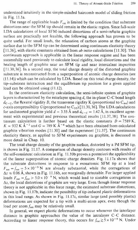
The range of applicable loads F", is limited by tbe condition that substratedistortions near the SFM tip should remain in the elastic region. Since full-scaleLOA calculations of local SFM-induced distortions of a semi-infinite graphitesurface are practically not feasible, the following approach has proven to bequite useful. For small loads, the relaxation of carbon atoms at the graphitesurface due to the SFM tip can be determined using continuum elasticity theory[11.36J, with elastic constants obtained from ab initio calculations [11.30). Thiscontinuum approach is applicable in the linear response regime and has beensuccessfully used previously to calculate local rigidity, local distortions and thehealing length of graphite near an SFM tip and near intercalant impurities[11.30,36). In a second step, the total charge density of the distorted graphitesubstrate is reconstructed from a superposition of atomic charge densities (see(11.J4») which can be calculated by LDA. Based on this total charge density, thetip-substrate interaction and the equilibrium tip position for a given appliedload can be obtained using (11.12).
In the continuum elasticity calculation, the semi·infinite system of graphitelayers is characterized by the interlayer spacing d, the in·plane C-e hond lengthdc - c, the flexural rigidity D, the transverse rigidity K (proportional to Coo) andc·axis compressibility G (proportional to C33 ) [11.30,36]. The LDA calculationsfor undistorted graphite yield d = 3.35 Aand dc - c = 1.42 A, in excellent agree·ment with experimental and previous theoretical resuhs [11.37,38). The con·tinuum calculation is further based on the elastic constants D =.7589 K,K = 932 K A-, and G = 789 K A-0 which have been obtained from calculatedgraphite vibration modes [11.30] and the experiment [11.37). The continuumelasticity theory, as applied to SFM experiments on graphite, is discussed inmore detail in Chap. 10.
The total charge density of the graphite surface, distorted by a Pd SFM tip,is shown in Fig. 11.17. A comparison of charge density contours with results ofthe self-consistent calculation in Fig. 1l.lOb proves a posteriori the applicabilityof the linear superposition of atomic charge densities. Fig. 11.17a shows thatthe substrate distortions in response to a monatomic SFM tip at a loadF~, = !'" ~ 5 X 10⁻⁹ N are already substantial, while the corrugations oftu '" 0.06 A, shown in Fig. 11.16b, are marginally detectable. For larger appliedloads F", =!'" > 5.0 X 10- 9 N, which would lead to sizeable corrugations intu, the local distortions of graphite are very large. Even though linear responsetheory is not applicable in this force range, the estimated substrate distortions,shown in Fig. 11.17b, indicate the possibility of tip·induced plaslic deformatioosin this load range. As shown in Fig. II.17c, similar large (and possibly plastic)deformations arc expected for a tip with a multi·alom apex, even though theload per atom !... may be relatively small.
In general, we expect plastic deformations to occur whenever the interlayerdistance in graphite approaches the value of the intralayer C-e distance.According to linear response theory, this occurs for !~,~5 x 10- 9 N. Under

"'" ".11. T ""-" _, f'" • NSF", ' •...,""1alI ,,,."""~ -... "' -. 'llo-.. _ c:o..,,,,," 01 _ ... p _ ...
J"plo..fI<~'""" -.... no _ 10<....... 101 '~.J...I.'\I··" '.w-/-I • ,0 .,.. .ppI><d ... _'''''' .'" ItJ 10,, __ y_ w IJ. I~·',. • ....- ""'. J..,,,,,, "p. III<
"'" " ,.~ _'0".. <"-0. <1<_" ..-....,,, • 'hhj. I' n. 1otIo,_ .. 'llo .Pj'tI«I ,,.,,......... ,,,. N _ .. ,., __ aI,'" ,,,,kM.:.,at
"" II (11111
'hue oond'lLQnl.~.,,,,o,.,,ibl< r.hybfl-J .... IKoIl or ,.,boIl .xboub (,,,", Jl~pll.11>0; Sp' to d'I",ond h~e 'p' bondi"ll 'i 1t~.1110 <><>.1J' bel"'" lhe l'p ...... Ao.."mall: "f 'h. onlt..1SFM f",c< for 'hil pl.. ,,~ tl<:f"rma'mn. wMch <l"", nol,.Iy ('In lhe (on"n~~m " ..uc"y thO<'lry. hOI b<oen O"I.,oed ,n • finl'pr11><lpkt'~kollllQfl [11.39) 01 1110 .nph.uto-di.mond 1,.m'llO" lIS ~ 10HClio" of <Xl.rnaIplm",oIJon. lhe ".ohne 0 ...., n....: '1:'1,,11., w".,po",d'''K (u." ·i,,~n'l.l,
."."de<lllp", ,nd''''.1 CI'lIcill r"'l% 1"" .",f..,. .l"m ur{." _ 10 • N fur lnu"""," '"'' I')uo 10 T" II,. nnorol tlll'::hly of MIlIp""" In,. I",ao ;"c...."'" byhllf a., Ndor nf ml.n'ltok {O, a one·llom "I', m IlJWmm< ",uh ,11< VlILlC
<1"",«1 atoo••A mIll'" S~M "I''' m()te COll\P~' Ihan lhe mod.1 "I' discu.K<l abo.! and
ooul<l """'II ul • ,n"''''.:'1' "f ,M. Uf few .I"m. "" 1"1' or I 11rJ<'1' "f:'
" .,,",,'an"al f""1 inn or Ihil 1"'Be! "I' ",",ukI, '~"'"Bh lbe ""cw~""," or. <on·Ilm,naU.m 1110' [II 'I) 0' I il"llphll< fla"lI 1.40,41], dt>ltlbul< IIf<: ."ph",1lca<! morr '~'oI, 10''''' I JIl"jt .~l>Ilr.. , .ro ... '«lLlCf: (htI3f1t <01"'0'11"'1 OCIr,be up fha. 1111] .~d HltreUe tbe mm"nUm Rpa.."on bol"",.n .'01'11,,"J~t'e" Th... dra:t Id ,,,,,,ca,,, lhe uPfO=' I'mi, or '"rHclbl. IOilda /," comp".'bk ..',~ rI "lIo.1ra1< dd"""""looo••Oll m."C "ond... rucI"c Im.,;n. 01,,,rflce ,,,po.npl1.. r..al".... Ind 01 Uld.". ftl<"llOn "n lhe .lOm'e 'K"l'k I'O,,-,ibl.( I 1,3~J
"'__01, I 1!>1ot~,_ n n.-.o. l!iol ....oJ H _J GM<_"'" .. _ .. Do- G
Oo<""'l'.10< ",...."""'II4,1CO ...,,., I',,,,,,I...--r Of'" Olfa <i 1'<.....K_.--...... I'IXlII ..O(l.I,I,.. .. 0<0:_",

11. Theory of Atomic-Scale Friction 291
References
II.l A summary of the present knowledge in tribology can be found in Adhesion and Friction, ed.by M. Grunze, H.J. Kreuzer: Springer Sec in Surf. Sci.. Vol. 17 (Springer, Berlin Heidelberg1989)
1J.2 e. Mathew Mate, Gary M. McClelland, Ragnar ErJandsson, ShirJey Chiang: Phys. Rev. Lett.59, 1942 (1987)
11.3 G.M. McClelland: In [11.1]11.4 J. Spreadborough: Wear 5, 18 (1962)11.5 R.D. Arnell, 1.W. Midgley, D.G. Teer: Proc. lost. Mech. Eog. 179, 115 (1966)11.6 1. Skinner, N. Gane, D. Tabor: NaL Phys. Sci. 232, 195 (1971)J 1.7 G. Binnig, e.F. Quate, Ch. Gerber: Phys. Rev. LetL 56, 930 (1986): ibid. Appl. Phys. Lett. 40,
178 (1982); G. Binnig, Ch. Gerber. E. Stoll, T.R. Albrecht, e.F. Quate: Europbys. Lett. 3,1281(1987)
11.8 Uzi Landman, W.D. Luedtke, A. Nilzan: Surf. Sci. 210, L177 (1989); Uzi Landman,W.D. Luedtke, MW. Ribarsky: J. Vac. Sci. TechnoL A 7,2829 (1989)
11.9 W. Zhong. D. Tomanek: Phys. Rev. Lett. 64, 3054 (1990)IUO L.D. Landau. EM. Lifshitz: Course of Theoretical Physics, VoL I: Mechanics (Pergamon,
Oxford (960) p. 12211.11 The optimum selection of C is characterized by strong A-C and B---C bonds, while C itself
should have a low shear modulus.11.l2 G.A. Tomlinson: Phil. Mag. S. 7, Vol. 7,905 (1929)11.13 D. Tomanek, w. Zhong, H. Thomas: Europhys. Lett. 15, 887 (1991)11.14 E. Meyer, R. Overney, L. Howald, D. Brodbeck, R. LUlhi, H.-1. Guntherodt: In Fundamentals
of Friclion, ed. by I. Singer, H. Pollock: NATO-Advanced Study Institute Series (Kluwer,Dordrecht 1992)
11.15 lE. Sacco, J.B. Sokoloff, A. Widom: Phys. Rev. B 20,5071 (1979)11.16 W. Zhong, G. Ovemey, D. Tomanek: Europhys. Lett. 15,49 (1991)ILl7 W. Kohn, LJ. Sham: Phys. Rev. 140, Al133 (1965)11.18 e.T. Chan, D. Vanderbilt, S.G. Louie: Phys. Rev. B 33, 2455 (1986); C.T. Chan,
D. Vanderbilt, S.G. Louie, J.R. Chelikowsky: Phys. Rev. B 33,7941 (1986)11.19 M. Anders, C. Heiden: (submitted for publication)11.20 e. Horie, H. Miyazaki: Phys. Rev. B 42, 11757 (1990)11.21 R. Smoluchowski: Phys. Rev. GO, 661 (1941)J 1.22 This effect is also responsible for the large value of the surface diffusion constant on graphite
and apparent small sensitivity of surrace friction to adsorbed films. as discussed in [11.6]11.23 l8. Pethica, W.e. Oliver: Physica Scripta T 19, 61 (1987); J.P. Batra, S. Ciraci: Phys. Rev.
Leu. GO, 1314 (1988)11.24 S. Gould, K. Burke, P.K. Hansma: Phys. Rev. B 40,5363 (1989)11.25 F.F. Abraham and l.P. Batra: Surf, Sci. 209, L125 (1989)11.26 D. Tomanek, W. Zhong: Phys. Rev. B 43, 12623 (1991)11.27 M.S. Daw, M.l. Baskes: Phys. Rev. B 29, 6443 (1984)11.28 In the following, I denote microscopic forces per atom bYfand macroscopic forces applied on
large objects by F11.29 Near f,,,, = 5 X 10- 9 N, the potential V is essentially constant across the graphite surface,
which leads to f.l ~ 0 (Fig. 11.14). Small deviations from this behavior can arise due totip-induced substrate deformations and small inaccuracies in the energy formula given in(11.12)
1J.30 D. Tomanek, G. Overney, H. Miyazaki, S.D. Mahanti, l-U. Glintherodt: Phys. Rev. Lett. 63,876 (1989); ibid.. 63, 1896(E) (1989)
I J.31 H.J. Mamin, E.. Ganz, D.W. Abraham, R.E. Thomson, J. Clarke: Phys. Rev. B 34,9015 (1986)11.32 L.D. Landau, E.M. Lifshitz: Course of Theoretical Physics, Vol. 7: Theory of Elasticity,
(Pergamon, Oxford 1986) p. 53

292 D. Tomimek: Theory of AlOmic-Scale Friction
11.33 S. Ciraci, A. Baratoff, I.P. Batra: Phys. Rev. B 41,2763 (1990); LP. Batra, S. Ciraci: 1. Vac. Sci.Tuhnol. A 6, 3D (1988)
11.34 U. u.ndman, W.D. Luedtke, N.A. Burnham, RJ. Colton: Science 248, 454 (1990)11.35 E. Meyer, H. Heinzelmann, P. Gruller, Th. lung, Th. Weiskopf, H.-R. Hidber, R. u.pka,
H. Rudin, H.-l. Gil.ntherodt: 1. Microsc. 152, 269 (1988)11.36 S. Lee, H. Miyazaki., S.D. Mahanti, SA Solin: Phys. Rev. Letl- 62, 3066 (1989)J1.37 H. Zabel: In Graphite Intercalation Compounds, ed. by H. Zabel, SA Solin: Topics in Current
Phys. Vol. 14 (Springer, Berlin Heidelberg 1989).(1.38 CT. Chan, K.M. Ho, W.A. Karnitakabara: Phys. Rev. B 36, 3499 (1987); CT. Chan,
W.A. Kamitakahaca, K.M. Ho, P.C Eklund: Pbys. Rev. Letl- 58, 1528 (1987)11.39 S. Fahy, S.G. Louie, M.L Cohen: Phys. Rev. B 34, 1191 (1986)J1.40 lB. Pethica: Phys. Rev. Lett. 57, 3235 (1986)J1.4 [ G. Ovemey, D. Tomanek, W. Zhong, Z. Sun, H. Miyazaki, S.D. Mahanti, H.1. Giintherodt:
J. Phys.: Condo Mat. 4,4233 (J992)