11 Shear Walls
47
1 Shear walls • column – stiffening element • stiffness: EI wall >> EI column
-
Upload
christopher-singleton -
Category
Documents
-
view
31 -
download
3
Transcript of 11 Shear Walls

1
Shear walls
• column – stiffening element
• stiffness: EIwall >> EIcolumn

2
Rigidity of stiffening elements
H2 >> H1Rigid walls – decrease of deflections δ and more simple foundations
Stiffening elements
Column systems without stiffening elements –deflections and big bending moments
Almost all lateral loads –carried by shear walls and stiffening elements

3
Shear walls (stiffening elements)
• contribute to overall stiffness of the building + provide stability
• correct design of shear walls = condition of reliability and efficiency of the structure
• transfer lateral loads to basement• shall be designed so that all lateral load is
carried by shear walls (stiffening elements)
Principles of arrangement of stiffening elements
• use of existing structural members →• stiffening elements shall carry all lateral load• stiffening elements shouldn't restrain
deformations due to shrinkage, creep and temperature changes
• avoid torsion of the building• stiffening elements shall carry a big part of
vertical loads• stiffening elements should have big moments
of inertia• of stiffening elements´ axis shouldn't intersect
in one point

4
no point of intersection of stiffening element axis
Behaviour and design of shear walls
• according to governing deformation
Deformation• predominantly bending• predominantly shear

5
• If walls with different type of deformation are combined in one structure, bending and shear deformation (stiffness) must be considered in analysis.
• Deflection due to – Bending– Shear (usually neglected)

6
Stiffness of walls
Stiffness in bending
4% (16%) proportional share of shear in total stiffness – shear effect neglected
Combined stiffness Stiffness in shear
32
≥HB
≤
51
81
HB
32
51
≥≥HB
Stiffness of walls
(Mohr principle)• Load the dual beam with moment
factored by stiffness
• Deflection ≈ moment on dual beam due to factored load M
EIWHM =
EIWHHH
EIWHy
332
21 3
==

7
Stiffness of walls
Stiffness = load that cause deflection equal to one
yHEIW 3
3= 3
3HEIK =
Stiffness in bending
3
3HEIK =

8
Shear stiffness
deflection due to shear
shear stiffness

9
Shear stiffness
HAGK S κ
=
Combined (complex) stiffness
shearbendingcombined KKK111
+=

10
Procedure of analysis of a building with shear walls
1st step • Divide lateral load to particular stiffening
elements (shear walls)
2nd step• Design of the wall• Check the wall stability (or max. deflection)
3rd step• Design of reinforcement
Dividing of load to walls –according to stiffness of walls

11
• stiffening elements + other loadbearingelements = statically indeterminate system
• simplified idealisation – preliminary design– interpretation and check of detailed analysis
Proportioning of lateral load to stiffening elements
According to layout• statically determinate
- proportioning from equilibrium of forces- (the most simple case: shear walls)
• statically indeterminate- further simplifying assumptions

12
Simplified method – idealisation
• flooring plates rigid for transferring lateral load
• pinned connection of floor slab and stiffening element, rigidity of the floor slab in its plane
Idealisation• stiffness of shear walls is
negligible perpendicular to the plane of the wall and negligible stiffness in torsion; stiffness of other vertical elements is also negligible
• stiffening elements don't change section along height
• buildings with rectangle shape may be analyzed separately with two directions of lateral load only
EIy>>EIx
EIx≈ 0, stiffness in torsion ≈ 0
wx
wy

13
• According to layout of stiffening elements the analysis is performed as:– 2D or – 3D.
• Stiffening systems: – statically determinate– statically indeterminate
For statically determinate systems the load carried by one wall may be determined from equilibrium conditions.
– graphically– by numerical calculations

14
Graphical determination of load carried by shear walls in statically determinate system
Calculation of load carried by one wall (statically determinate system)
Here: stiffnesses of all walls are equal

15
Dividing of wind load to particular walls (statically determinate system) – example
Wind load could be solve for 2 directions (x and y) and separately
Equilibrium conditions (in a plan): forces, momentsHere: stiffnesses of all walls are equal
12 12 6
lx = 30
B
C
A
4 x
A =
2
l y =
12
6 Wx
Wy y
x
cmcmcm EEIE ⋅=⋅⋅= 6,362,0121 3
xA WW =
152302
22xyxy
x
yC
WWWWlTW
W +=⋅
+=+=1522
xy
x
yB
WWlTW
W −=−=
12 12 6
lx = 30
B
C
A
4 x
A =
2
l y =
12
6 Wx
Wy y
x
Height of the building 33m. Three walls of same dimensions (B=6m, H=33m, t=0,2m) and same stiffness.
Load Wx: carried by wall A
Wall A is in nonsymetric position - Wx applies a torsional moment T= Wx .xA
Load Wy is carried by walls B and C. WB =WC= Wy /2Torsion: WB = -T/l, WC= T/l
Total lateral load for walls B,C:

16
Dividing of wind load to particular walls –general procedure
Due to lateral load the floor slab moves and rotates. 3 unknowns: translations Δx, Δy, rotation φ→ 3 equilibrium equations
∑=
=n
iixx WW
1∑
=
=m
ijyy WW
1
∑ ∑−=− ixijyjyxixyj yWxWeWeW
Origin – in centre of gravity
n
x i ii
K y1
0=
=∑m
yj jj
K x1
0=
=∑
stiffness of wall j in direction y stiffness of wall i in direction x

17
translation of point
forces in walls due to translation and rotation
i ix x yϕ∆ = ∆ −
i iy y xϕ∆ = ∆ +
( )xi i xiW x y Kϕ= ∆ −
( ) yjjyj KxyW ϕ+∆=
From equilibrium conditions we obtain Δx, Δy, φ
Consequently load of particular walls may be determined
n
x i ii
K y1
0=
=∑m
yj jj
K x1
0=
=∑
i ix x yϕ∆ = ∆ − i iy y xϕ∆ = ∆ +
( )xi i xiW x y Kϕ= ∆ −( ) yjjyj KxyW ϕ+∆=
new system of coordinatesorigin of coordinates – centroid of stiffness (centroid of bending)
translations of point
forces in walls due to translation and rotation

18
equilibrium of forces and moments (load and forces due to translations and rotation)
∑=
=n
iixx WW
1∑
=
=m
ijyy WW
1∑ ∑−=− ixijyjyxixyj yWxWeWeW
substitution (unknown Δx, Δy, φ) ;
∑=
=∆ n
ixi
x
K
Wx
1∑
=
=∆ m
jjy
y
K
Wy
1∑ ∑
= =
+
−= n
i
m
jjjyixi
yxxy
xKyK
eWeW
1 1
22ϕ
( ) yjjyj KxyW ϕ+∆=
calculation of forces in particular walls:
effect of bending effect of torsion
After the total load is distributed to particular shear walls→
design and check of each wall

19
Design of shear walls
• common requirement: no tensile stresses at bottom of the wall for operational load(repeated changing of compression and tensile is unsuitable)
Tensile at bottom section of the wall

20
Shear wall - stability check
• Check of stability – EQU • possible demand: check of stress at the
bottom-section of the wall (service load; characteristic value) : no tension
• Check of max deflectionfmax ≤ flim
Stability of a wall
Mdst ≤Mstb
Stability condition – EQU
Destabilizing moment
Stabilizing moment
γG = 1,1 γQ = 1,5 γG = 0,9 γQ = 0

21
Note:
event. check of the stability of the whole system (building)
Elastic behaviour of wall
M N V
principle tensile ~ fct → reinforcement according to detailing

22
Walls with predominantly shear deformation
yI
MAN
x +=σ 0=yσItSV
⋅⋅
=τ
22
2,1 22τ
σσσσσ +
+±
+= yxyx
ctdf≤1σ ctdf⟩1σ
M, N, V
Linear analysis

23
• Heavily loaded walls with shear straining could be analysed by means of strut-and-tie method.
Tall walls (predominantly bending deformation)
• simplified analysis method: reinforcement design from normal stresses at bottom section of the wall
• Method is suitable for walls ca 5 m long

24
Simplified analysis of a tall wall
1. check of the stress at bottom
2. stability check
3. reinforcement design
γG = 1 γQ = 1
γG = 1,35 γQ = 1,5
γG = 1,1 γQ = 1,5
γG = 0,9 γQ = 0
γG = 1 γQ = 1,5 γQ =0
≤51
81
HB
Wall = cantilever, stress at bottom section 1-1´

25
recapitulation: Simplified analysis of tall wall (dominating bending stiffness) –procedure:
1. total horizontal load2. dividing of load to particular walls (according to
stiffness of walls)3. design of a wall
i. check of the stress at bottoma. wind load (γQ = 1) and vertical load (γG = 1 γQ = 1)
ii. stability check iii. reinforcement design :
a. max. wind load (γQ = 1,5) and max. vertical load (γG = 1,35γQ = 1,5)
b. max. wind load (γF = 1,5) a min. vertical load (γG = 1) → if tensile occurs – design tensile reinforcement
ad 3) wall design
charakteristické γF návrhové γF návrhové γF návrhovéStálé
0,9 1,1 1,35
Celkem stálé g k = g d = g d = g d = Nahodilé
1,5 1,5 1,5
q k = q d = q d = q d = Celkem (g+q) k = (g+q) d = (g+q) d = (g+q) d =

26
ad 3) wall design
ad 3) wall design– stability
γG = 1,1 γQ = 1,5
γG = 0,9 γQ = 0

27
ad 3) wall design – reinforcement design
• combination M + N
– moment from the central plane– slenderness– imperfections
wind load
ad 3) wall design – reinforcement designwind load + vertical loads
1 m
4,4 m
γG = 1,35 γQ = 1,5 vertical loads γG = 1, γQ = 0
horizontal loads γG = 1,35 γQ = 1,5
tensile reinforcement

28
ad 3) wall design – reinforcement design
N [kN]
-6000,0
-5000,0
-4000,0
-3000,0
-2000,0
-1000,0
0,0
1000,0
2000,0
-200,0 -150,0 -100,0 -50,0 0,0 50,0 100,0 150,0 200,0
M [kNm]
[M Ed,N Ed] tlak
[M Ed,N Ed] tah
ad 3) wall design – reinforcement design
Compression in footing section: (2nd order effect - slender, short column)
Tensile in footing section:
Main (vertical) reinforcementAs,min =0,002Ac (each surface 1/2 As,min )spacing ≤3t, ≤400mm
ydSt fAN ⋅=
sScdCEd AfAN σ⋅+=

29
Procedure of analysis of a building with shear walls
1st step • Divide lateral load to particular stiffening
elements (shear walls)
2nd step• Design of the wall• Check the wall stability (or max. deflection)
3rd step• Design of reinforcement
30
Simplified method of analysis of high wall with bending stiffness (shear effect neglected)
No tensile stress for service (operational) load in footing bottom
Design of reinforcement (compression force) -load situations
• max. lateral load + min. vertical load • max.lateral load + max. vertical load
≤
51
81
HB
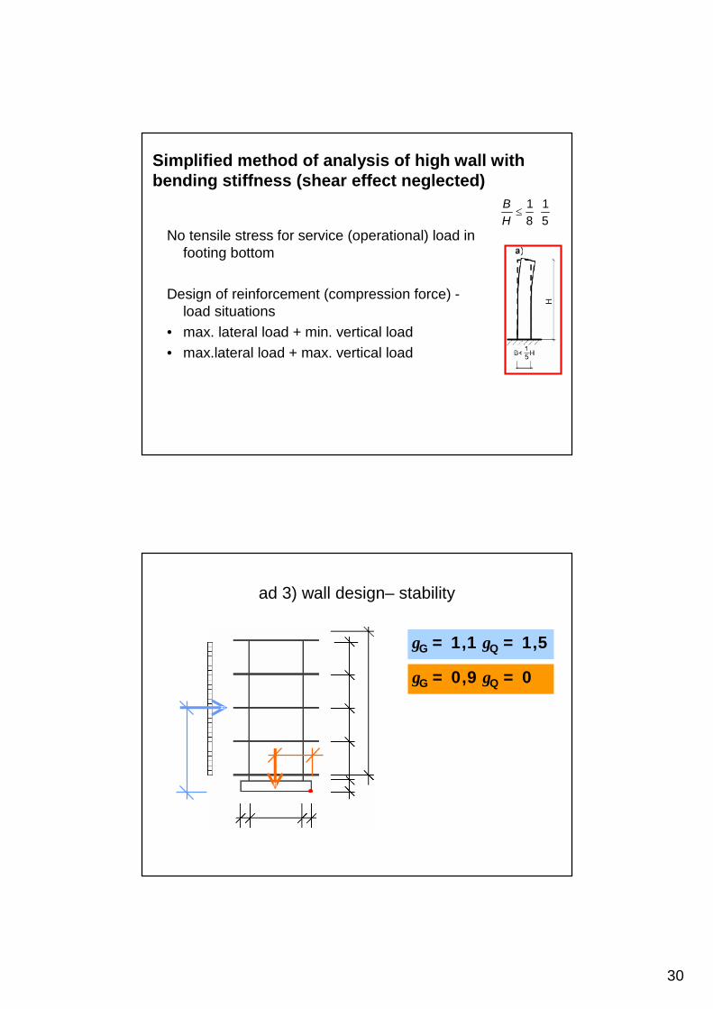
ad 3) wall design– stability
γG = 1,1 γQ = 1,5
γG = 0,9 γQ = 0

31
max. wind load (γQ = 1,5) and max. vertical load (γG = 1,35γQ = 1,5)
max. wind load (γF = 1,5) a min. vertical load (γG = 1) → if tensile occurs – design tensile reinforcement
Reinforcement design – normal forces
NRd = 0,8 Ac fcd + As σs
NRd = As fyd
Stiffening walls with openingsa) flexible cross beams - coupled wallsb) stiff cross beams - one wallc) medium cross beams

32
Flexible coupling beam
M M lI I1
1
1 2=
+
M M lI I2
2
1 2=
+
two cantilevers - connected - same deformation- proportion of moment - due to stiffness
Stiff cross beams
design of coupling (cross) beam
One wall in calculation of moment of inertia Ired use section

33
Z t hi i= τ
τiSid
red
V St I
=
ZV Sh
IiSid
red=
M Z lSd i=12
V ZSd i=
Design of coupling (cross) beam
shear force in i-storey:
substitution:
Reinforcement in coupling beam:
Medium cross beams
Stiffness of cross beam {0, ∞}2
21 HwM ⋅=
lZMMM ⋅++= 21
ZZ
M2
M1
l

34
Medium cross beams
Structure could be analysed as a frame:
part of the tie-beam has infinite stiffness
part at the opening is flexible
Reinforcement of coupling beam
• cantilever• ties• edge reinforcement• diagonal reinforcement• edge of the wall – U-shaped reinforcement

35
Reinforcement - detailing
Main - longitudinal reinforcement
As,min =0,002Ac (at least 1/2 As,min each edge of wall)spacing ≤3t, ≤400mm
As,max =0,04Ac ......... 0,08 Ac (in lapping area)
Secondary (horizontal) reinforcement
As ≥ 25% of main As
≥ 0,001Ac
spacing ≤ 400mm
Purpose:
• keep position of main reinforcement during grouting
• shrinkage cracking, cracks due to temperature changes

36
Ties: if As of main reinf. ≥ 2% Ac
spacing and ∅ − same as for columns
∅ ≥1/4 ∅ of main reinf.
≥ 6mm
spacing ≤ 12 ∅ of main reinf.
≤ t
≤ 300mm
reduced spacing of ties below and above ceiling – distance 4t
at least 4 ties per 1m2 of wall
If reinf. is provided as a weld mesh : φ ≤ 16 mm, cover > 2 φ.
buď
nebo
either
or
ties
lappingties

37

38

39

40

41
example
Wx
Wy
lx = 36
l y =
24
A
B
E D
C
x x0
y0 y
x0 = 4 xD = 2
yB
= -9
y
0 = 3
yA
= 9
xC = -16 xE = 14
6 6 6 6 6 6
6
6
6
6
Wx = 800 kN Wy = 1200 kN.
43
)18612(=
++−=
++⋅+⋅+⋅
=I
IIII
xIxIxIxEDC
EEDDCCo
32
)612(=
−=
+⋅+⋅
=I
III
xIxIyBA
BBAAo
centre of bending :
translations, rotation
resultant forces in walls
IEIEIEIEW
K
WxcmcmBcmAcm
xn
ixi
x 4002800
==+
==∆
∑ IEIEIEIEIEw
K
Wy
cmcmEcmDcmCcm
xn
jyj
y 40031200
==++
==∆
∑
( )( ) IEIIIIIExKyK
eWeW
cmEDCBAcmn
i
m
ijjyixi
yxxy 88,31421699
38004120022222
1 1
22−=
⋅+⋅+⋅+⋅+⋅⋅+−⋅
=+
−=
∑ ∑= =
ϕ
( ) ( ) 365988,3400 =⋅−=⋅−∆= AcmAA IEyxW ϕ
( ) ( ) 435988,3400 =⋅+=⋅−∆= BcmBB IEyxW ϕ
( ) ( ) 9,3371688,3400 =⋅−=⋅+∆= CcmCC IExyW ϕ
( ) ( ) 8,407288,3400 =⋅+=⋅+∆= DcmDD IExyW ϕ
( ) ( ) 4,4541488,3400 =⋅+=⋅+∆= EcmEE IExyW ϕ

42
Proportioning of lateral load –statically indeterminate system
• different stiffness of different elements (different character of deformation)
simplifying assumptions for deformation - composite element
Design and analysis of combinedsystems
Effect of loads are usually solved separately for parts of the building or particular elements (assumed elastic
behaviour).

43
Analysis model – stability
• stiffening elements + other load-bearing elements = statically indefinite system
• numerical model – computer analysis• laboratory tests (tunnel)• simplified idealisation • deformation properties of the idealised structure
shall not differ from real behaviour
Analysis model
• In linear analysis effect of vertical and lateral loads may be analysed separately and superimposed
• The whole structure may be divided to structural parts or elements and these are solved separately
• Non-linear solution

44
Different behaviour of vertical elements
• different properties – stiffness –simplification – idealisation
Char. deformation of column system, wall system and combination
frame wall combined structure

45
linear solution – simplification • separate effects of loads → and other• divide to particular elements• analyse particular elements
• (nonlinear solution – all loads analysed together)
Structural model
• column – stiffening element
• stiffness: EIwall >> EIcolumn

46
Combination of different types of elements in one system
Interaction of different types of vertical elements – idealisation
• composite prism• substitute stiffness (continuous continuum
along the building height
RIGID slabs

47
Dividing of effects of loads to particular elements
• assumptions:– slabs rigid in their central plane– pinned connection of slabs and vertical stiffening
elements– slabs transfer load to vertical stiffening elements – stiffening element = cantilever fixed to basement
• According to arrangement of stiffening elements in a plan – plane or spatial (3D) system is assumed